1
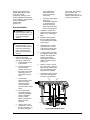
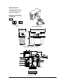
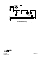
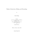
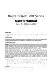
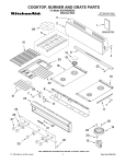
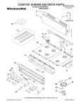
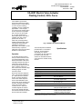
Valve and Actuator Manual 977
Actuators and Positioners Section
Product Bulletin VA-8051
Issue Date 0988
VA-8051 Electric Valve Actuator
Floating Control, 50 lb. Force
The VA-8051 synchronous,
motor-driven actuator provides
floating control of valves with up
to 3/4 in. stroke in heating,
ventilating, and air conditioning
applications. This compact,
non-spring return actuator has a
50 lb. force and is compatible
with a 3-wire, 24 VAC signal.
A ± 12 VDC signal from a
DSC-8500 may be used with a
VA-8000-104 drive card to
position the VA-8051. A
3400 ohm (nominal) position
feedback potentiometer is also
included for remote position
indication to meters or a
DSC-8500. The VA-8051 can be
ordered factory coupled to
VB Series Valves. See AV-8051
bulletin for code numbers.
Operation
A controller sends 24 VAC to
the up or down terminal on the
circuit board depending on the
desired movement of the valve.
This signal causes the motor to
rotate in the proper direction,
and through the lead screw and
lever, move the valve up or
down. When the controller stops
sending a signal, the valve
remains in place.
When the controller closes the
valve, a shutoff force will build
up. When this force reaches
50 lbs., the lever activates a
force sensor which stops the
motor. Field calibration of the
force sensor is not required. The
actuator maintains the shutoff
force even if power to the
controller is lost. When the
controller signals the valve to
move in the opposite direction,
the shutoff force will be reduced
and the valve will modulate.
Fig. 1: VA-8051-1 Connected to VB-3754
Specifications
The internal position feedback
potentiometer is connected to
the R, W, and S terminals.
Specifically, the wiper is
connected to W. The wiper will
be at the R end when the
actuator is retracted and at the
S end when the actuator is fully
stroked.
Product
VA-8051-1 Electric Valve Actuator
Control Mode
Floating Control, 3-W ire
Supply Voltage
24 VAC + 6 V, -4V, 200 mA, 50/60 Hz
Power Consumption
6 VA
Feedback
3400 Ohms ± 25%, 20 VDC Max Input Voltage
Shutoff Force
50 lb. Force Minimum
Stroke Time
1/2 in. Stroke: Approx. 65 Sec
3/4 in. Stroke: Approx. 90 Sec
Ambient Operating Temperature
0 to 140°F (-18 to 60°C), 90% RH Max,
85°F Max Dew Point
Ambient Storage Temperature
-40 to 150°F (-40 to 65°C)
Media Temperature
Water: 190°F (88°C)
Steam (with Insulator Kit): 280 °F (138°C)
Accessories
VA-8000-101 Steam Insulator Kit
VA-8000-102 Valve Position Indicator Kit
VA-8000-104 Auxiliary Interface Board
The performance specifications are nominal and conform to acceptable industry standards. For application at conditions
beyond these specifications, consult the local Johnson Controls office. Johnson Controls, Inc. shall not be liable for
damages resulting from misapplication or misuse of its products.
© 1988 Johnson Controls, Inc.
Part No.14-548-9 Rev. A
Code No. LIT-977305
1
Wiring
All wiring must be in accordance
with applicable electrical code
requirements. Input lines to the
actuator must be wired correctly
for the valve to move in the
proper direction.
2
VA-8051 Product Bulletin
Wiring is to a terminal strip
labeled DWN (Down), COM
(Common) and UP,
respectively. Wiring is to the
terminals labeled R (Retracted
end), W (Wiper), and S (Stroked
end) for the feedback
potentiometer.
(See Fig. 6).
spring plate off the
valve. Remove the
spring compression
tool if used.
f.
Retrofit Installation
!
!
1.
CAUTION: Do not use on
valves having a stroke over
3/4 in. Actuator travel over
3/4 in. will damage the
actuator.
WARNING: Equipment
Damage Hazard. Do not
drive the VA-8051 actuator
unless it is mounted to a
valve. This can result in
permanent damage to the
actuator.
Remove the V-3000
actuator, upper spring plate
and spring. (See Fig. 2).
a. Disconnect the air line
to the actuator.
b.
Remove the actuator
by loosening the
actuator set screw on
the bottom of the lower
diaphragm case. Lift
the actuator off of the
valve.
c.
Hold the stem
extension firmly with a
9/16 in. box-head
wrench and with a
small screwdriver,
loosen the stem locking
screw.
d.
For V-3000 valves,
compress the spring
using the X-200-8058
spring compression
tool. For V-3800
valves, compress the
spring with hand
pressure.
e.
Using a 9/16 in. boxhead wrench, unscrew
the stem extension. Lift
the spring and upper
Thread the lower spring
plate up the
centerpiece stuffing box
to increase spacing
between the spring
plate and the flat valve
yoke mounting surface.
2.
Unpack the actuator and
make sure the lever plate is
within 1/4 in. of the upper
stop.
3.
Install the valve packing
that is provided according
to the instructions included
with the parts.
4.
Thread the 1/4 in. Palnut,
open side down, onto the
valve stem and all the way
to the end of the threads.
5.
Loosely install the actuator
by sliding the actuator yoke
between the spring plate
and the yoke surface.
Finger tighten the plate to
hold the actuator in place.
(See Fig. 3).
6.
Obtain a source of 24 volt
AC power. Wire a switch to
allow control of the 24 volts
AC to the DWN and COM
terminals of the actuator.
7.
Thread the coupler onto the
valve stem while applying
24 volts AC as necessary.
The coupler should thread
down the stem until
approximately 1/8 in. of
thread remains between the
coupler and the Palnut.
Fig. 2: Exposed V-3000 Actuator
VA-8051 Product Bulletin
3
8.
Reverse the actuator and
drive it up until it stops on
the limit switch. Check to
make sure the gap between
the lever plate and the
molded upper stop is
1/16 in. (.047 to .093 in.).
Set with flat washer gage
supplied. (See Fig. 5).
Repeat steps 6, 7 and 8
until the gap falls into this
range when the actuator
stops.
9.
With the valve driven fully
up to hold tension on the
stem and coupler, thread
the Palnut up the stem until
it contacts the coupler.
Tighten Palnut to coupler
with 1/2 in. and 7/16 in.
wrenches.
10. Secure the actuator in place
by tightening the spring
plate with a large
screwdriver.(See Fig. 3).
11. Drive the actuator fully up
and down at least three
complete cycles before
again checking that the
lever and its drive coupler
stop before contacting the
upper stop and the lower
end of the yoke casting.
!
4
CAUTION: Use
VA-8000-101 Insulator Kit
for steam applications
280°F (138°C) Maximum.
VA-8051 Product Bulletin
Repair Information
Field repairs must not be made.
For a replacement VA-8051,
contact the nearest Johnson
Controls branch office.
Application and Drawing
Identification
Fig. 3: Isometric Drawing
Fig. 4: VA-8051-1 Dimensions in./mm.
Fig. 5: Internal View
VA-8051 Product Bulletin
5
Fig. 6: DSC-8500 Application Wiring
(Incremental Control with Position Indication or Proportional Control)
Controls Group
507 E. Michigan Street
P.O. Box 423
Milwaukee, WI 53202
6
VA-8051 Product Bulletin
Printed in U.S.A.