1
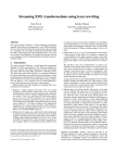
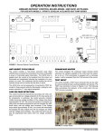
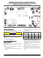
REPAIR PART INSTALLATION MANUAL
HEAT PUMP COMMUNICATING CONTROL REPAIR KIT (S1-33102957000)
MODELS YZB, YZE, YZH, HL5, HC5, HL8, HC8
FIGURE 1: Demand Defrost Control Module
GENERAL INFORMATION
3.
The YorkGuard VI Demand Defrost control as a replacement
part for prior versions of the YorkGuard control.
TABLE 1: Defrost Initiate Curves
Following the detailed instructions for modifications of both
the indoor and outdoor units is critical.
NOTE: For direct replacement of YorkGuard VI, replace the
control only.
Service replacement kit consists of:
• YorkGuard “VI” Defrost Control.
CONTROL CONFIGURATION FOR
ALL APPLICATIONS
Defrost Curve
Selection
Jumper Position
1.
2.
Specify the desired Low Temperature Cut Out (LTCO)
using the jumper on the control.
Specify the desired Balance Point (BP) using the jumper on
the control.
Johnson Controls Unitary Products
1
2
3
4
YZB/HC3B/HL3B 2 & 2.5 Ton 4 & 5 Ton 3 & 3.5 Ton 1.5 Ton
YZE/HC5B/HL5B
2 Ton
4 & 5 Ton
3 Ton
N/A
YZE03811
N/A
N/A
3 Ton
N/A
4.
Verify that the Y2 LOCK jumper is set. This jumper is not
applicable to a single stage compressor system.
5.
Specify if the Heat Pump is installed with a fossil fuel furnace using the FFUEL jumper. The jumper should be ON
for a fossil fuel furnace installation and OFF for an air handler installation.
6.
Specify Switch Point jumper using the jumper on the control.
7.
Verify that the HOT HEAT PUMP is set appropriately.
8.
Specify compressor delay using jumper on the control.
“ON” will shut-off compressor when entering and leaving
defrost.
Most jumper settings should be set to match jumpers on board
being removed.
Remove control from packaging and configure the control as
follows:
Specify appropriate defrost curve using the jumper on the
control. See Table 1.
035-22286-001-A-0909
OUTDOOR UNIT MODIFICATIONS
1.
Disconnect all high and 24V voltage power to the unit and
the control circuit.
2.
Mark and disconnect all thermostat, sensor and low voltage control connections from the YorkGuard IV control.
FOSSIL FUEL APPLICATION - The YorkGuard VI control does
not require an add-on fossil fuel kit. Remove existing fossil fuel
kit if present. An optional bonnet sensor may be used if desired.
See “OPERATION INSTRUCTIONS - “DEMAND DEFROST
CONTROL BOARD” on upgnet.com for details of functionality
with and without bonnet sensor installed.
3.
Remove the six #10 screws holding the control and remove
the control.
START-UP OPERATION
4.
Using five of the six screws removed in Step 3, mount the
new board in place (omit the top middle screw).
5.
1.
Reapply power to the unit and the control voltage circuit.
2.
The LED on the defrost control will flash on and off when
there is power to the control and it is working properly.
3.
Verify unit operation.
Reconnect the wires removed in Step 2.
INDOOR UNIT MODIFICATIONS
NOTE: Indoor transformer should be rated for a minimum of
40VA. Replace transformer if necessary.
For more information on control operation, refer to “OPERATION INSTRUCTIONS - “DEMAND DEFROST CONTROL
BOARD” on upgnet.com.
Subject to change without notice. Published in U.S.A.
Copyright © 2009 by Johnson Controls, Inc. All rights reserved.
Johnson Controls Unitary Products
5005 York Drive
Norman, OK 73069
035-22286-001-A-0909
Supersedes:Nothing