1
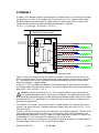
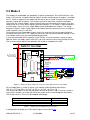
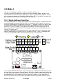
Manual for the NMRA compatible DCCaccessory decoder
Assembled WDECN-TN
Parts Kit WDECN-TN-B
© 2006 Gerard Clemens
1.1 Properties
This model railroad accessory decoder is based on the ATMEL ATTiny2313 microcontroller.
The decoder has 4 pairs of outputs and executes most of the DCC1 commands for accessory decoders as defined by the NMRA2. Therefore the decoder can be used with other
compatible DCC products and control systems like Arnold-Digital, Uhlenbrock, Lenz-Digital
Plus, Roco-Digital, Fleischmann, Digitrax and Zimo.
The software in the decoder is very complete and supports:
•
•
•
•
•
•
•
•
•
•
•
•
Configuration by means of CV3 on a dedicated programming track or on the main track
(POM4 ). On the programming track CVs can be written and read
Adjustable duration of the output timing (0.0065536 s – 1.6777 s and continuous)
NMRA compatible, processes all usual DCC commands for accessory decoders.
Configurable flashing for each individual output.
Flashing outputs with adjustable frequency and duty cycle.
5 different modes of operation for accessories like dual coil turnout and signal motors,
magnetic decouplers or accessories which require continuous outputs like light signals
and MRR5 illumination.
A second decoder address can be configured to allow for more signal aspects or to
automatically control the aspect of one signal by the position of a turnout or the aspect
of a following signal.
Memorization of the actual signal aspect allows to power up in the last state before
power down.
Up to 40 different signal aspects using 2 decoder addresses or 32 signal aspects using
a single output address.
Decoder addressing from 1 - 510 (2040 turnouts) or output addressing from 1 - 2046
All outputs can be individually inverted (alternating flash lights at crossroads)
Prototype like dimming between signal aspect transitions. Duration can be defined with
a CV.
Hardware
•
•
•
•
•
Low cost, high performance ATMEL ATTINY2313 Microprocessor
Simple and robust hardware on an industrial quality printed circuit board.
Small size 50 x 80 mm with four 3 mm screw holes
Output current 500 mA per output, ca. 1 A per decoder
Separate terminals for external power supply (MRR transformer) or power from the
DCC track voltage.
This product is not a toy! It is not intended for use by children under 14 years. The part kit contains small parts. Keep it out of
the hand of children younger than 3 years. Caution: This product has sharp edges and pins which might cause injuries. Misapplication might lead to fire hazard. Please follow the instructions of this manual to avoid injury or hazard by this product.
* Arnold, Digitrax, Lenz, Roco and Zimo are registered trade marks.
WDecN-TN-EN V2.1
01.09.2006
1 of 31
2 Wiring the decoder
Terminals 1 and 2 of terminal strip K3 must be connected to the DCC track signal. The polarity of the DCC signal has no influence on the function of the decoder. It will work either
way. The ~ terminals of terminal strip K1 must be connected to a MRR transformer with an
output voltage of 14 – 18 VAC. If no MRR transformer is available the DCC track voltage
may also be applied. This has some disadvantages: the valuable digital DCC power generated by a digital booster6 is used for turnouts or lamps and not for its original purpose of driving rolling stock. The round rectifier next to K1 is not very well suited to rectify the audio frequent DCC signal and may cause a distortion of the wave form.
The left terminal of terminal strip K1 is connected to the internal ground signal of the decoder. This terminal can be used to power the illumination of mechanical signals where the
dual coils and one pole of the illumination is connected to one of the decoder’s plus terminals on K4 – K7.
Caution: This internal decoder ground may in no case be connected to any other
ground or mass connection of your layout. It can solely be used for accessories which
not only require the common positive internal decoder voltage but also the internal ground.
The current drawn between the common plus terminals and the internal ground terminal
must not cause a decoder overload.
WDecN-TN can easily be configured for 5 different modes of operation, each suited for different applications. These 5 modes are explained in more detail hereafter:
2.1 Mode 0
This mode of operation allows the user to independently control each one of the 8 outputs.
Each output can be switched on or off independent of the state of the other outputs. It deploys the standard accessory command as defined by the NMRA. This command contains
one particular bit which defines the state of the addressed output, ON or OFF.
Now most of the commercial digital command stations do never send the command to switch
an output OFF and leave it up to the decoder to maintain the active output or to switch it off
after a time delay.
For this reason mode 0 can only be used with selected command stations. If your command
station allows commanding both the ON and OFF state of an output, the WDecN-TN in
Mode 0 is the most universal decoder you can think of. It allows controlling turnouts, illumination but also light signals with up to 256 different aspects.
Required configuration:
CV 33 = 0 or 128 (with memorization of the last output state), CV 29 = 128, CV 3 – CV 6 = 0.
CV 46 for flashing and CV 37 for dimming can of course also be used in Mode 0. For special
applications you can also use the times in CV 3 – CV 6 to limit the duration of the output
pulse. E.g. the duration of impulses to electromagnetic decouplers could be limited by a fixed
time rather than by the duration of your finger pushing a button. Since there are 4 timers, 2
adjacent outputs share one timer and will both have the same time limitation.
Tip: When you operate the IntelliBox using the LocoNet protocol, both telegrams (ON and
OFF) will be send. When operating the IntelliBox directly or using the P50X protocol it will
only send the ON commands.
WDecN-TN-EN V2.1
01.09.2006
2 of 31
2.2 Mode 1
In mode 1 the 8 decoder outputs are organized in 4 adjacent pairs. In a pair only one output
can be active at a time, i.e. the outputs are mutually exclusive. This feature makes mode 1
the ideal mode for twin coil turnout or signal motors or simple signals with 2 aspects only.
To operate twin coil turnout motors following configuration is required:
CV 33 = 1, CV 29, Bit 6 = 0 and CV 3 - CV 6 > 0
digital DCC track voltage
14 - 18 V AC from a
MRR transformer or
digital track voltage
Int. Gnd
K1
~
~
8
K7
+
Turnout 4
7
6
K6
+
Turnout 3
5
4
K5
+
Turnout 2
3
DCC
WDecN-TN
K3
K4
2
+
Turnout 1
1
Figure 1 – Connecting 4 twin coil turnout motors
Figure 1 shows the wiring of 4 twin coil motors for turnouts. Each one of these drives contains 2 solenoids which must be connected to the screw terminals of the terminal strips K4 –
K7. The common wire of the 2 solenoids must be connected to the center terminal which
carries the decoder + supply voltage.
Using CV 3 - CV 6 you define the duration of the output impulse. When the twin coil drive
has end of stroke interrupting limit switches, you may also define the maximum possible time
delay (255 = 255 x 6.55 ms = 1.67 s).
Caution: If one or more of the CV 3 – CV 6 variables contain a zero value then the
corresponding output(s) will be continuously energized. The solenoid of the twin coil
drive could get overheated, burn out and/or damage the decoder output. Normal time values
are between 25 (0.17 s) and 50 (0.33 s). Larger time values and frequent usage may also
lead to overheating drives.
The WDecN-TN in mode 1 can also be used as a signal decoder for 4 signals with each 2
aspects (e.g. green and red). To obtain continuous outputs the timer values in CV 3 – CV 6
must be set to 0.
Of course you can use each one of the 4 output pairs for a different purpose. The pair on K4
may control a turnout; the pair on K5 serves a mechanical signal, while K6 operates on 2
electromagnetic decouplers. Finally K7 operates a light signal with 2 aspects. Timing for K4
is defined by CV 3; the timing for K5 is defined by CV 4, and so on.
Also in mode 1 you can use features like smooth transitioning of aspects, flashing outputs or
inverting outputs. See CVs 37, CV 46 and CV 48 for details.
WDecN-TN-EN V2.1
01.09.2006
3 of 31
2.3 Mode 2
The outputs of the decoder are grouped in 2 triplets and one pair. K4 and K5 terminal 1 are
triplet 1, K5 terminal 2 and K6 make up triplet 2 and the remaining pair of outputs is available
on K7. Within a triplet only one output can be active (on) at a time. A triplet can be used to
operate a signal with 3 aspects. The simplest case of a signal with 3 aspects would be a
signal with just 3 lamps (green, yellow and red) each one connected to an output. Only one
lamp can be lit at a time. When signals get more complex, i.e. an aspect is represented by 2
or more lamps, you must use a simple diode matrix to decode these aspects. The wiring
diagram in figure 2 shows a pilot signal of the federal German railways that uses 4 lamps to
show 3 aspects (Vr0, Vr1 and Vr2).
Please observe that the decoder outputs switch the accessory to internal ground and that
the center terminals of K4 – K7 supply the accessory with the internal positive voltage. If you
use a diode matrix it must be correspondingly polarized.
A very common diode for this purpose is the 1N4148. It can be used for currents of up to
200 mA. When you apply signals with LEDs you also need to insert current limiting resistors.
The resistors can be equally well placed in the anode or cathode of the LED.
Figure 2 – Wiring 2 signals with each 3 aspects and a twin coil accessory motor.
For the application as shown in figure 2 you need to make following adjustments:
(CV 33 = 2, CV 29, Bit6 = 0, CV 3 = 0, CV 4 = 0, CV 5 = 0, CV 6 > 0)
The remaining outputs on the red and green terminal of terminal strip K7 can be used for a
signal with 2 aspects, for a dual coil accessory motor or for 2 electromagnetic decouplers.
The timing values in CV 6 must be adopted accordingly:
Connected accessory
Light signal
Twin coil accessory (turnout/signal)
Twin coil accessory (with end of stroke limit switch)
Value in CV 6
0
30 – 80
30 – 80, max. 255
Table 1 – Values in CV 6 for different accessories
A configuration example for a Swiss dwarf signal can be found here.
WDecN-TN-EN V2.1
01.09.2006
4 of 31
2.4 Mode 3
(CV 33 = 3, CV 29, Bit6 = 0, CV 3 = 0, CV 4 = 0, CV 5 = 0, CV 6 = 0)
Using this mode of operation the decoder outputs are split in 2 groups of each 4 outputs. In
a group only one output can be active at any time. You can hook up 2 signals with each 4
aspects. If the aspects are represented by single lamps then these lamps can simply be connected with the 4 available outputs. Only one lamp will be lit at any time. In case your signal
is more complex and one or more of the 4 aspects are represented with 2 or more lamps you
must insert a diode matrix between signal and decoder to define which lamps are lit for each
of the 4 aspects. The wiring example in Figure 3 shows a main signal of the German federal
railways which uses 6 lamps to show 4 aspects (Hp0, Hp1, Hp2 und Sh1).
Important: Note: The decoder outputs switch to internal decoder ground. The positive supply
voltage is delivered on the 4 center terminals of K4 - K7 (drawn in blue). The diodes in your
matrix have to be polarized accordingly. A recommended diode type for a matrix is the low
cost 1N4148 with a 200 mA current capacity. Using signals with LED instead of lamps requires the use of current limiting resistor in series with each of the LEDs. The position of the
resistor may be chosen in the anode or cathode lead of the LED.
Mode 3 can also be combined with smooth transitioning of aspects, flashing and inverting.
Figure 3 – Wiring 2 signals with each 4 aspects.
HP0
HP1
HP2
Sh1
Figure 4 – The aspects Hp0, Hp1, Hp2 and Sh1 are controlled by one half of a WDecN-TN decoder
WDecN-TN-EN V2.1
01.09.2006
5 of 31
2.5 Mode 4
(CV 33 = 4, CV 29, Bit6 = 0, CV 3 = 0, CV 4 = 0, CV 5 = 0, CV 6 = 0)
In mode 4 you can freely define the output state of the 8 decoder outputs. Mode 4 is the
ideal mode to control more complex light signals. There is no dependency between the outputs, there are no groups and all outputs might be ON or OFF as you desire. On top of that
you may define which lamps in what aspect must be flashing.
2.5.1 Single Address Operation
The principle of mode 4 is looking up an aspect from a table of aspects. To pick the desired
aspect the decoder evaluates the 8 possible “on” commands for its 8 outputs. It translates
these DCC commands to an index with a value of 0 – 7. WDecN-TN takes this index to pick
an aspect from a table of 40 aspects. Each of the aspect definitions consists of 2 consequent CVs. The first CV (byte) is a bit pattern which defines the active output bits for the
aspect (see Figure 5 “Output mask”). The second CV contains the flashing attributes (see
Figure 5 “Flashing mask”).
The table of 40 aspects is contained in the CVs from 49 up to CV 128. In the default single
address mode you can only access the first 8 aspects (CV 49 – CV 64). The decoder consumes just one decoder address and the contents of CV 47 must be zero.
Figure 5 – Output numbering and definitions of the masks for an aspect
In this way the WDecN-TN offers a very easy-to-use way to adapt to the control of any kind
of signal with up to 8 aspects. Figure 6 shows a DR Hl main signal in combination with a light
bar and a pilot signal attached to a WDecN-TN. The total number of LEDs or lamps that can
be independently lit must not be more than the physical 8 outputs. If your application requires more than 8 LEDs or lamps then you might consider using a diode matrix to realize
WDecN-TN-EN V2.1
01.09.2006
6 of 31
the required function. On the MoBaTron.de web site you will find an example for the wiring
and the configuration of a DB signal combination consisting of a main signal and pilot signal
with a total of 9 LEDs.
Main Signal
digital DCC track voltage
R
R
R
1
+
R
2
K4
K3
WDecN-TN
DCC
3
+
R
K5
R
4
Pilot Signal
5
+
6
~
7
K7
+
R
8
K1
~
R
K6
14 - 18 V AC from a
MRR transformer or
DCC track voltage
Ground
Figure 6 – Wiring a combination of signals in Mode 4
2.5.2 Dual address operation
Many signals can show more than just 8 aspects. With the help of a second decoder address the WDecN-TN can extend the number of displayable aspects to 40 (theoretically 8 x 8
= 64 but limited to 40 due to memory restrictions). The second address must be entered in
CV 47 and just consist of the LSB of the address. The MSB of the second address is assumed to be identical to the MSB in CV 9. The second address may be a virtual address, i.e.
no decoder uses this address, but it can also be the address of a physical decoder.
In case the second address represents a physical decoder you can make the active aspect
depend on the state of that physical decoder (turnout(s) and/or other signal(s)). Especially in
combination with pilot signals as is the case with many Hl (DR) and Hp (DB) signals, aspects
may change dependent on the state of the next signal (next block). The aspect shown then
automatically announces the state of the next signal.
To be completely flexible in configuring the WDecN-TN offers 8 pointers in the array of 40
aspects (CV 49 up to CV128). So for each of the possible 8 states of the decoder under the
secondary address, you can assign a block of aspects. You may define 8 blocks each 5 aspects or define 5 blocks each 8 aspects large or even use the same block of aspects for
more than once for different states of the secondary decoder.
Use the CVs 38 up to 45 to define the starting indices in the array of aspects. The array of
aspects starts with CV49 and goes up to and including CV128. These 40 aspects are numbered 0 to 39 so an index can have a value of 0 up to 39. CV 38 defines the index for the
secondary encoder state 0, CV 39 defines the starting index for the secondary encoder state
1, and so on. Figure 7 explains this function graphically.
WDecN-TN-EN V2.1
01.09.2006
7 of 31
Figure 7 – Selection of signal aspects in mode 4 using 2 decoder addresses
This manual contains a configuration example in which the aspects to be displayed are identical for the states 1 and 2 of the secondary encoder (the next signal in this case). Therefore
the index 8 is used twice: once in CV 39 and once in CV40.
Again in this example you see that all non used aspects are configured to show the “Stop”
aspect. When anything goes wrong a halt will be displayed.
WDecN-TN-EN V2.1
01.09.2006
8 of 31
3 Programming the decoder
The NMRA compatible decoder WDecN-TN must be programmed using so called „Configuration Variables“ (CV). These configuration variables are bytes of information permanently
stored in the E²Prom memory of the decoder. The NMRA standards („RP“ = „Recommended
Practices“) define a basic mandatory set of variables with fixed functionality but also provide
ranges of CVs to be used by the decoder manufacturer for the configuration of the special
features of his decoder.
For accessory decoders the NMRA originally reserved the CVs from CV513 up to CV1024.
Since many command stations did not and still don’t support programming these upper CVs,
starting with firmware version V1.2 the WDecN-TN allowed programming the same variables
in the both the upper and lower range 1 – 512. In the latest RP 9.2.2 the CVs have now been
officially moved from CV513 – CV1024 down to 1 – 512. Usage of 513 – 1024 is now optional but still supported, also by the WDecN-TN. This document refers to both ranges and
now mentions the lower range first. E.g. CV 1 (CV513) contains the 6 lowest significant bits
of the accessory decoder address or the lower significant Byte of the output address when
used with output addressing. Table 8 starting on page 22 shows all implemented CVs.
The factory default value for CV 1 (CV513) is 1. Independent of the selected addressing
mode (decoder addressing or output addressing) the decoder accepts all accessory commands sent to address 1.
3.1 Service Mode programming (programming track)
Connect the DCC input terminals on K3 with the programming track output terminals of your
command station. Apply 14 -18V AC or DC from a model rail road transformer to the ~ terminals on K1. Follow the instructions of your command station to read or write CVs (direct
mode).
Due to the hardware concept of the WDecN-TN decoder it requires an AC or DC supply voltage in the 14 – 18 V range on the ~ terminals on K1 during service mode programming. If no such external power is available, you may consider using the DCC track
voltage. Using the programming track voltage for this purpose may work as well. In case of
problems consult chapter 6.
The accessory decoder WDecN-TN accepts all standardized DCC commands to read, verify
and write CVs. You can operate on bytes or on single bits. It is possible to read and write
not-used CVs. Some CVs are marked as “read only”. They can just be read. Trying to write
these variables will provoke an error on your command station.
Every successful service mode command will be acknowledged by the decoder. An acknowledge signal very briefly (6 ms) raises the DCC power consumption from the programming track. This raise in power consumption is detected by your command station which will
give an acknowledge message in its display. When it expects an acknowledge pulse from
the decoder but doesn’t get one it reports an error. When reading CVs your command station calculates the value of the CV by repeatedly sending bit verify commands and evaluating the returned acknowledge signals.
WDecN-TN-EN V2.1
01.09.2006
9 of 31
3.2 Operations Mode programming (main track)
Even when your preconfigured decoder has been mounted on your layout and receives its
DCC commands from the main track you can still change the values of most CVs using the
“Operations Mode” programming. This mode is also referred to as Programming On the
Main track (POM). Of course your digital command station must support operations mode
programming or “POM”. Please note that POM for accessory decoders differs from POM for
multi function decoders (because of the different addressing schemes). For example the
Uhlenbrock IntelliBox in V1.5 supports POM only for multi function decoders. The almost
identical Fleischmann Twin Center supports both POM for accessory decoders and for multi
function decoders.
Using POM you can address the decoder or the output depending of how you configured
your decoder to work.
The WDecN-TN in operations mode programming does not supply acknowledge signals like
it does in service mode programming. This implies that it is not possible to read variables in
operations mode.
WDecN-TN-EN V2.1
01.09.2006
10 of 31
3.3 Decoder Addressing Modes
3.3.1 Decoder addressing
A traditional DCC accessory decoder can normally control 4 output pairs (momentary or
maintained outputs). Decoders of this type are addressed with a Decoder Address. Commands to this address contain information about which pair (2 bit), which output in a pair (1
bit) and what output state is required (1 bit).
A total of 510 decoders is supported, each decoder providing control for 4 accessories. In
terms of turnouts this would allow for 2040 turnouts. Decoder 0 is not used and decoder address 511 is reserved for broadcasts commands – commands to be executed by all decoders.
To address a decoder in the range of 1 to 510 a 9 bit address is required. This 9 bit address
is split up in a 6 bit part and a remaining 3 bit part. The lower significant 6 bits are stored in
CV1 the remaining 3 higher significant bits are stored in CV 9. In CV 29, bit 6 you tell the
decoder with a 0 value that it has to process 9 bit addressing information.
How to split up a decoder address in a 6 bit and a 3 bit part is explained elsewhere in this
document. A simple method is using Table 11 in the appendix of this manual or using the
Excel Tool from the web site . Both tables an tool also give you a cross reference of decoder
address and turnout addresses on that decoder.
3.3.2 Output Addressing
For special accessories like signals with many aspects, servo decoders with several positions, or single function decoders – one turnout, one signal, etc. per decoder, the NMRA
defined a second addressing scheme with the name Output Addressing. This addressing
scheme can be mixed with decoder addressing and allows for effective use of the address
space for accessories.
Output addressing basically uses a 9 bit address as discussed above and adds the 2 bits
defining the output pair to it, so obtaining an 11 bit address.
This 11 bit address provides for a total number of theoretically 2048 accessories. Since the
addresses 0 and 2047 (broadcast) are not used, effectively 2046 accessories can be addressed. The 11 bit address is split up in an 8 bit lower significant part and in a 3 bit higher
significant part. These values must be stored in CV1 (LSB) and CV 9 (MSB). You inform the
WDecN-TN to apply output addressing by setting bit 6 of CV 29 to a “1”.
Especially in combination with the extended commands for accessory decoders, output addressing offers very powerful features. A single WDecN-TN on a single output address can
control a signal with up to 32 different aspects.
Of course your digital command station must support these “extended accessory decoder
control packets” and not many of them do so.
WDecN-TN can be configured for extended DCC accessory decoder commands by setting
CV 29 Bit 5 to a “1” value.
WDecN-TN-EN V2.1
01.09.2006
11 of 31
4 WDecN-TN Configuration Variables
This chapter provides detailed information about all Configuration Variables (CVs) of the
WDecN-TN accessory decoder. Examples will be used to help understand the functions.
CV 1 (CV 513) contains the 6 lower significant bits of the decoder address or the 8 lower
significant bits of the output address. In CV 29 bit 6 you define which of the addressing
schemes will be used (0 = decoder addressing, 1 = output addressing). CV 1 can only be
used in combination with CV 9 to define a complete 9 bit decoder address or a complete 11
bit output address.
Decoder addressing (see also Appendix A starting at page 28):
CV 29, Bit6 = 0 : CV 1 = Decoder number%64 (decoder number Modulo 64 or the
remainder after a division by 64).
Example: Decoder number = 200. (Contains the turnouts 797 – 800)
200 / 64 = 3 remainder 8 -> CV 1 = 8, CV 9 = 3
Output addressing:
CV 29, Bit6 = 1 : CV 513= output number %256 (output number Modulo 256 or the
remainder after a division by 256).
Example: Output number = 1200.
1200 / 256 = 4 remainder 176 -> CV 1 = 176, CV 9 = 4
CV 3 – CV 6 (CV 515 – CV 518) define the duration of the output activation for the output
pairs 1 to 4. The time is defined as the number of 6.5536 ms increments. For electromagnetic turnout and signal dual coil drives an activation time of ca. 0.33 s = 50 increments is a
good value. Entering a 0 value causes the active output to remain energized until it is explicitly de-energized (e.g. by another aspect, by the other output of a pair).
CV 7 (CV 519) contains the firmware version of the decoder. The actual version is 2.1 which
is represented by a value of 21. This is a read only variable.
CV 8 (CV 520) contains the manufacturer identification number. This number is assigned by
the NMRA. For the WDecN-TN the manufacturer ID = 24 (MoBaTron.de). This is a read only
variable.
CV 9 (CV 521) contains the most significant bits of the decoder or the output address. With
CV 29, bit 6 you define whether decoder addressing (bit 6 = 0) or output addressing (bit 6 =
1) is active. CV 9 must be used together with CV1 to specify the complete 9 bit decoder address or a complete 11 bit output address.
Decoder addressing (see also Appendix A starting at page 28):
CV 29, Bit6 = 0 : CV 9 = Decoder number / 64 (result of the integer division of the
decoder number by 64). These are the 3 most significant bits of the 9 bit decoder address.
Example: Decoder number = 200.
200 / 64 = 3 remainder 8 -> CV 9 = 3, CV 1 = 8
Output addressing:
CV 29, Bit6 = 1 : CV 9 = output number / 256 (result of the integer division of the output number by 256).
Example: Output number = 1200.
1200 / 256 = 4 remainder 176 -> CV 9 = 4, CV 1 = 176
WDecN-TN-EN V2.1
01.09.2006
12 of 31
CV 29 (CV 541) Configuration of the decoder. This is a bit mask in which single bits activate
functionalities. The properties can be changed bit wise. This is the meaning of the bits:
Bit 0
Bit 1
Bit 2
Bit 3
Bit 4
Bit 5
Bit 6
Bit 7
Meaning
Default
reserved
reserved
reserved
Bi-Directional communication, always off (0)
Reserved
Type: 0 = Basic Accessory Decoder,
1 = Extended Accessory Decoder
Addressing 0 = decoder addressing
1 = output addressing (see chapter 3.3.2)
7
Decoder type: 0 = Multi Function Decoder (not implemented)
1 = Accessory decoder
0
0
0
0
0
0
Bit
value
1
2
4
8
16
32
0
64
1
128
Table 2 - Properties of CV29
CV 33 (CV 545) defines the mode of operation of the decoder. CV 33 is only valid if the decoder has been configured as basic accessory with decoder addressing (CV 29, bit 5 = 0
and CV 29, Bit 6 = 0). Most of the actual DCC command stations can address the decoder
only when it has been configured this way.
Value
0
1
2
3
4
128
129
130
131
132
Function
Mode 0. Evaluate the status bit in the standard DCC accessory command. Allows to energize
or to de-energize the individual outputs of the decoder. This mode is not supported by all digital command stations because they normally do not send commands to de-activate outputs.
Mode 1. Control of 4 pairs of outputs. Output duration is defined by CV 3 – CV 6. This is the
standard for the control of 4 turnouts. Zero values in CV 3 – CV 6 make the outputs maintained and turn the decoder into a signal decoder for 2-aspect signals, illumination, or motorized drives (relays required).
Mode 2.Control of 2 triplets and one pair of outputs. Can be used to operate two 3-aspect
signals and one dual coil accessory or 2-aspect signal. CV 3, 4 and 5 must contain 0. CV 6
defines the behavior of the last pair, maintained or momentary.
Mode 3. Control of two 4-aspect signals. CV 3 – CV 6 must contain zero values.
Mode 4. Control of 8 independent outputs. Mode 4 is used to display up to 8, or up to 40 8-bit
aspects. Each of these aspects consists of a bit pattern defining the active outputs and a bit
pattern defining the flashing property of active outputs. Aspects must be stored in CVs 49 128 and are accessed using indices. Using 1 decoder address you can access 8 aspects,
using 2 addresses you can access up to 40 aspects. Aspects can be organized in groups and
a set of 8 pointers defines the starting index of a group. Which pointer (1 – 8) is used is controlled by the information received on the second decoder address. The second address must
be entered in CV47; the pointers are defined in CV 38 – CV 45.
Mode 0 with storage of the last state
Mode 1 with storage of the last state. Should not be used with turnouts because they remember their last state mechanically.
Mode 2 with storage of the last state
Mode 3 with storage of the last state.
Mode 4 with storage of the last state.
Table 3 – Properties of CV 33
CV 34 (CV 546) defines the frequency of the internal flash generator. The duration of one
period must be entered in units of 6.55 ms. For a flashing frequency of 2 Hz (500 ms) you
would need to enter a value 500 / 6.55 = 76. The factory default for CV 34 is 100 (~1.5 Hz).
See also CVs 35 and 46.
WDecN-TN-EN V2.1
01.09.2006
13 of 31
CV 35 (CV 547) is used to define the duty cycle of the internal flashing generator. The value
you enter in CV35 must always be less than the value you entered in CV34. If you enter a
value equal or greater than the value in CV 34 the flashing turns into steady lighting (> 100%
on). When you enter a value of 0 in CV 35, the duty cycle is 0% on and the outputs activated
for flashing will be off all the time. See also CVs 34 and 46.
CV 36 (CV 548) controls the smooth transitioning between different signal aspects. On some
prototype signals an aspect slowly dims, then there is a short dark phase and the new aspect smoothly appears. The duration of these 3 phases is defined with CV36. The time is
expressed in units of 6,55 ms. The factory default for CV36 is 20 which leads to a phase
duration of about 120 ms for dimming and lighting up. The dark phase is always half this
time. Smooth transitioning does only make sense for light signals and could lead to damage
or malfunction when applied to twin coil accessory motors. See also CV37)
CV 37 (CV 549) defines for which of the 8 decoder outputs the smooth transitioning is active
(see CV36). CV 37 is a bit mask in which bit 0 represents output 1R; bit 1 represents output
1L; bit 2 corresponds to output 2R and so on. If you want to enable smooth transitioning for
all outputs, you would enter a value of 255 in CV37. See also CV 36.
CV 38 – CV 45 (CV 550 – CV 557) contain 8 indices in the array of aspects (CV 49 – CV
128). The indexing in the array of aspects is only active in mode 4. If your WDecN-TN only
uses its basic decoder address in CV1 and CV9, you can access the range of 8 aspects as
defined by the contents of CV 38. The default value of CV38 is 0, so you would be able to
access the 8 aspects stored in CV 49 – CV 64. (Changing the contents of CV 38 using POM
would allow you to access the other 32 aspects). If your decoder also uses a second address (CV 47 > 0) then the second address controls the selection of the pointer (1 - 8). This
mechanism also allows to automatically control the active aspect of a signal based on the
status of another decoder be it signal or a turnout decoder.
CV 38 : Index of the first aspect within a group of up to 8 aspects that will e active when the
decoder with the secondary address decodes an “on” command for its output #0. The value
of CV 38 may range from 0 to 39.
CV 39 : Index of the first aspect within a group of up to 8 aspects that will e active when the
decoder with the secondary address decodes an “on” command for its output #1. The value
of CV 39 may range from 0 to 39.
Etc. etc. for the CVs 40 – 45.
The tables Table 4, Table 5, Table 6 and Table 7 starting at page 17 show a practical example for the application of WDecN-TN for German Hl signals.
CV 46 (CV 558) is used to define which outputs must flash in modes 0 – 3. Bits 0 - 7 correspond to the outputs 1 – 8. When a bit is set the corresponding active output will flash.
Flashing only makes sense for signals and warning lamps. See also CV34 and CV 35.
CV 47 (CV 559) contains the 6 least significant bits of the secondary decoder address that
will be evaluated in mode 4 to control the selection of the pointer into the array of aspects.
This variable is only active in Mode 4. The most significant 3 bits of the secondary decoder
address are taken from CV 9, so both the primary and secondary decoder address must be
in same range, sharing the same 3 most significant bits.
WDecN-TN-EN V2.1
01.09.2006
14 of 31
CV 48 (CV 560) contains a bit mask which defines which outputs will be inverted. This mask
can be used to create alternating flash lights as required for cross roads. CV48 can also be
used to generate simple aspects in mode 2 or 3 without having to use a diode matrix. This
variable should be left zero when the decoder is used to control dual coil accessories.
A typical example that makes use of inverting outputs is the Swiss dwarf signal with 3 aspects. This signal has 3 lamps. Always 2 out of 3 lamps are lit to show the 3 aspects. Here
you will find the documentation for this application.
CV 49, CV 51, CV 53 . . . . CV 127 (CV 561, CV 563, CV 565 . . . . CV 539) contain the up to
40 signal aspects (bit patterns representing active outputs) which can be displayed in 3
ways:
CV 29, bit 5 = 0 and CV29, bit 6 = 0, CV 33 = 4, CV 47 = 0, CV 38 = 0
You can display any one of the first 8 signal aspects
CV 29, bit 5 = 1 and CV 29, bit 6 = 1, CV 47 = 0, CV 33 = 1/default, CV 38 =0/default.
Up to 32 signal aspects can be displayed using the NMRA extended accessory commands. The decoder uses output addressing. Note that extended accessory commands are not supported by all digital command stations.
CV 29, bit 5 = 0 and CV 29, bit 6 = 0, CV 33 = 4, CV 47 > 0
Depending on the status of the secondary decoder in CV 47 the decoder selects a
group of aspects to display. Using its own status it picks an aspect from the active
group. This mechanism allows to select any one of the up to 40 aspects from the array of aspects (CV 49 – CV 128).
Each one of the 40 aspects needs to be defined in 2 subsequent CVs in the 49 to 128 range.
The first one of these 2 CVs contains the bits that must be set active and he second one
contains the active bits that must flash. Bits correspond to decoder outputs: Bit 0 = output 1
and Bit 7 is output 8. Table 4, Table 5, Table 6 and Table 7 show an example configuration
for an Hl signal with pilot signal and signal bars. This example also shows the dependency
on the state of the next signal, e.g. the secondary decoder.
CV 50, CV52, CV 54 . . . . CV 128 (CV 562, CV 564, CV 566 . . . . CV 640) contain the
masks that define which of the active outputs in an aspect must flash.
4.1 Extended commands for accessory decoders
These commands have already been implemented in the firmware of the WDecN-TN.
Probably none of the known DCC command stations can issue these commands.
The commands are:
• Extended accessory decoder command (allows the selection of one out of 32 signal
aspects using one single accessory address).
• Extended accessory decoder broadcast command. This command allows to send a
single command which will be received an executed by all accessory decoders capable of executing broadcast commands. Could be used to set all signals to a stop aspect.
• POM for extended accessory decoders. This could be used to change aspects
online, e.g. by means of a computer control program.
WDecN-TN-EN V2.1
01.09.2006
15 of 31
4.2 Reset to default factory settings
To return the WDecN-TN to factory settings it has to be configured for address 0. This can
be achieved by setting both CV1 and CV 9 to a 0 value. The reset to factory defaults does
apply to the values in CV 49 – CV 128.
•
•
•
•
•
•
•
•
•
The Address of the decoder will be set to 1
The output time delays in CV3 – CV6 will be set to 50 (0.32s)
Mode of operation (CV 33 = 1 / standard turnout decoder)
Storage of last state will be disabled
Decoder addressing will be active (CV 29, Bit 6 = 0)
Standard accessory decoder command will be active (CV 29, Bit 5 = 0)
Smooth transitioning between signals aspects will be off (CV 36 = 20, CV 37 = 0)
Flashing and inverting will be disabled (CV46 = 0, CV48 = 0)
The secondary decoder address (CV 47) will be set zero.
WDecN-TN-EN V2.1
01.09.2006
16 of 31
4.3 Example configuration for Mode 4
yellow line
green line
red
top yellow
bottom yellow
green
Bit 7
Bit 6
Bit 5
Bit 4
Bit 3
Bit 2
Bit 1
Bit 0
Value
1
0
0
0
1
0
0
0
136
yellow
CV 49
Main signal
green
Pilot signal
Index/aspect
0 / Hp0
CV 50
0
0
0
0
0
0
0
0
0
CV 51
1
0
0
0
0
1
1
0
134
1/
Hl12a
CV 52
1
0
0
0
0
0
0
0
128
CV 53
1
0
1
0
0
1
1
0
166
2/
Hl12b
CV 54
1
0
0
0
0
0
0
0
128
CV 55
0
1
0
1
0
1
1
0
86
3 / Hl11
CV 56
0
1
0
0
0
0
0
0
64
CV 57
0
1
0
0
0
1
0
0
68
4 / Hl10
CV 58
0
0
0
0
0
0
0
0
0
CV 59
1
0
0
0
1
0
0
0
136
5 / Hp0
CV 60
0
0
0
0
0
0
0
0
0
CV 61
1
0
0
0
0
1
0
0
136
6 / Hp0
CV 62
0
0
0
0
0
0
0
0
0
CV 63
1
0
0
0
0
1
0
0
136
7 / Hp0
CV 64
0
0
0
0
0
0
0
0
0
Table 4 – Example configuration for an Hl main signal with pilot signal and light bars. The signal controlled by the secondary decoder address shows the Halt aspect (value 0). CV 38 = 0
WDecN-TN-EN V2.1
01.09.2006
17 of 31
green
yellow line
green line
red
top yellow
bottom yellow
green
CV 65
Main signal
yellow
Pilot signal
Bit 7
Bit 6
Bit 5
Bit 4
Bit 3
Bit 2
Bit 1
Bit 0
1
0
0
0
1
0
0
0
Value
Index / aspect
136
8 / Hp0
CV 66
0
0
0
0
0
0
0
0
0
CV 67
1
0
0
0
0
1
1
0
134
9 / Hl9a
CV 68
1
0
0
0
0
1
0
0
132
CV 69
1
0
1
0
0
1
1
0
166
10 /
Hl9b
CV 70
1
0
0
0
0
1
0
0
132
CV 71
0
1
0
1
0
1
1
0
86
11 / Hl8
CV 72
0
1
0
0
0
1
0
0
68
CV 73
0
1
0
0
0
1
0
0
68
12 / Hl7
CV 74
0
0
0
0
0
1
0
0
4
CV 75
0
0
0
0
0
0
0
0
0
13 /
Hp0
CV 76
0
0
0
0
0
0
0
0
0
CV 77
0
0
0
0
0
0
0
0
0
14 /
Hp0
CV 78
0
0
0
0
0
0
0
0
0
CV 79
0
0
0
0
0
0
0
0
0
15 /
Hp0
CV 80
0
0
0
0
0
0
0
0
0
Table 5 – Example configuration for an Hl main signal with pilot signal and light bars. The signal controlled by the secondary decoder address (next signals) shows the aspect „slow speed / 40/60 km/h“.
CV 39 = 8, CV 40 = 8
WDecN-TN-EN V2.1
01.09.2006
18 of 31
green
yellow line
green line
red
top yellow
bottom yellow
green
Main signal
yellow
Pilot signal
Bit 7
Bit 6
Bit 5
Bit 4
Bit 3
Bit 2
Bit 1
Bit 0
Value
CV 81
1
0
0
0
1
0
0
0
136
CV 82
0
0
0
0
0
0
0
0
0
CV 83
1
0
0
0
0
0
1
1
131
Index / aspect
16 / Hp0
17 / Hl6a
CV 84
1
0
0
0
0
0
0
1
128
CV 85
1
0
1
0
0
0
1
0
162
18 / Hl6b
CV 86
1
0
0
0
0
0
0
0
128
CV 87
0
1
0
1
0
0
1
1
83
19 / Hl5
CV 88
0
1
0
0
0
0
0
1
65
CV 89
0
1
0
0
0
0
0
1
65
20 / Hl4
CV 90
0
0
0
0
0
0
0
1
1
CV 91
1
0
0
0
1
0
0
0
136
21 / Hp0
CV 92
0
0
0
0
0
0
0
0
0
CV 93
1
0
0
0
1
0
0
0
136
22 / Hp0
CV 94
0
0
0
0
0
0
0
0
0
CV 95
1
0
0
0
1
0
0
0
136
23 / Hp0
CV 96
0
0
0
0
0
0
0
0
0
Table 6 – Example configuration for an Hl main signal with pilot signal and light bars. The decoder with
the secondary address (next signal) shows „limited speed/ 100 km/h“. CV 41 = 16
WDecN-TN-EN V2.1
01.09.2006
19 of 31
green
yellow line
green line
red
top yellow
bottom yellow
green
CV 97
Main signal
yellow
Pilot signal
Bit 7
Bit 6
Bit 5
Bit 4
Bit 3
Bit 2
Bit 1
Bit 0
Value
1
0
0
0
1
0
0
0
136
Index / aspect
24 / Hp0
CV 98
0
0
0
0
0
0
0
0
0
CV 99
1
0
0
0
0
0
1
1
131
25 / Hl3a
CV 100
1
0
0
0
0
0
0
0
128
CV 101
1
0
1
0
0
0
1
1
163
26 / Hl3b
CV 102
1
0
0
0
0
0
0
0
128
CV 103
0
1
0
1
0
0
1
1
83
27 / Hl2
CV 104
0
1
0
0
0
0
0
0
64
CV 105
0
1
0
0
0
0
0
1
65
28 / Hl1
CV 106
0
0
0
0
0
0
0
0
0
CV 107
1
0
0
0
1
0
0
0
136
29 / Hp0
CV 108
0
0
0
0
0
0
0
0
0
CV 109
1
0
0
0
1
0
0
0
136
30 / Hp0
CV 110
0
0
0
0
0
0
0
0
0
CV 111
1
0
0
0
1
0
0
0
136
31 / Hp0
CV 112
0
0
0
0
0
0
0
0
0
Table 7 – Example configuration for a main signal with pilot signal (DR Hl Signal).The decoder with the
secondary address (next signal) shows the aspect “safe, full speed” (status=5). CV 42 = 24,
CV 43, 44 and 45 contain zeros, so they point to the aspects for Halt on next signal.
WDecN-TN-EN V2.1
01.09.2006
20 of 31
4.4 Summary of all CVs
CV #
1
2
3
4
5
6
7
8
9
10
11
12
13
14
15
16
17
18
19
20
21
22
23
24
25
26
27
28
29
30
31
32
33
34
35
36
37
38
39
40
41
42
43
44
45
46
47
48
49
50
51
52
53
54
55
56
57
58
59
60
61
62
63
64
65
CV #
(optional)
513
514
515
516
517
518
519
520
521
522
523
524
525
526
527
528
529
530
531
532
533
534
535
536
537
538
539
540
541
542
543
544
545
546
547
548
549
550
551
552
553
554
555
556
557
558
559
560
561
562
563
564
565
566
567
568
569
570
571
572
573
574
575
576
577
CV Name
Default
value
Comment
Decoder Address LSB
Auxiliary activation
Time On F1 (outputs 1 and 2)
Time On F2 (outputs 3 and 4)
Time On F2 (outputs 3 and 4)
Time On F2 (outputs 3 and 4)
Manufacturer Version Info
Manufacturer ID
Decoder Address MSB
Reserved by NMRA for future use
Reserved by NMRA for future use
Reserved by NMRA for future use
Reserved by NMRA for future use
Reserved by NMRA for future use
Reserved by NMRA for future use
Reserved by NMRA for future use
Reserved by NMRA for future use
Reserved by NMRA for future use
Reserved by NMRA for future use
Reserved by NMRA for future use
Reserved by NMRA for future use
Reserved by NMRA for future use
Reserved by NMRA for future use
Reserved by NMRA for future use
Reserved by NMRA for future use
Reserved by NMRA for future use
Reserved by NMRA for future use
bi-directional communication configuration
Accessory decoder configuration
Reserved by NMRA for future use
Reserved by NMRA for future use
Reserved by NMRA for future use
Configuration of mode of operation
Flashing frequency
Flashing duty cycle
Smooth transition time f. signal aspects
Smooth transition mask
Index for signal aspect 1 of next signal
Index for signal aspect 2 of next signal
Index for signal aspect 3 of next signal
Index for signal aspect 4 of next signal
Index for signal aspect 5 of next signal
Index for signal aspect 6 of next signal
Index for signal aspect 7 of next signal
Index for signal aspect 8 of next signal
Flashing output mask (Modes 0 - 3, see CV 33)
Next signal decoder address LSB (6 Bits)
Inversion mask
Bit pattern aspect 1
Flashing mask for aspect 1
Bit pattern aspect 2
Flashing mask for aspect 2
Bit pattern aspect 3
Flashing mask for aspect 3
Bit pattern aspect 4
Flashing mask for aspect 4
Bit pattern aspect 5
Flashing mask for aspect 5
Bit pattern aspect 6
Flashing mask for aspect 6
Bit pattern aspect 7
Flashing mask for aspect 7
Bit pattern aspect 8
Flashing mask for aspect 8
Bit pattern aspect 9
1
0
50
50
50
50
21
24
0
255
255
255
255
255
255
255
255
255
255
255
255
255
255
255
255
255
255
255
128
255
255
255
1
100
50
20
0
0
0
0
0
0
0
0
0
0
0
0
0
0
0
0
0
0
0
0
0
0
0
0
0
0
0
0
0
1 - 63
Bit mask 0-255 (not implemented)
0 –255, 0 = continuous output
0 –255, 0 = continuous output
0 –255, 0 = continuous output
0 –255, 0 = continuous output
Read Only (V 2.1)
Read Only (MoBaTron.de = 24)
0 – 7 (max. 512 Decoders)
WDecN-TN-EN V2.1
01.09.2006
Bit mask (not implemented)
Bit mask
0 – 4, 128 – 132
100 x 0,00655 s=0,65536s (ca. 1,7 Hz)
CV 547 < CV 546
ca. 120 ms
Bit mask 0 – 255
1 – 40 which aspect must be shown?
1 – 40 which aspect must be shown?
1 – 40 which aspect must be shown?
1 – 40 which aspect must be shown?
1 – 40 which aspect must be shown?
1 – 40 which aspect must be shown?
1 – 40 which aspect must be shown?
1 – 40 which aspect must be shown?
Which outputs must be flashing?
MSB = CV 9
0 – 255 which outputs must be inverted?
Index 0
Index 0
Index 1
Index 1
Index 2
Index 2
Index 3
Index 3
Index 4
Index 4
Index 5
Index 5
Index 6
Index 6
Index 7
Index 7
Index 8
21 of 31
66
67
68
69
70
71
72
73
74
75
76
77
78
79
80
81
82
83
84
85
86
87
88
89
90
91
92
93
94
95
96
97
98
99
100
101
102
103
104
105
106
107
108
109
110
111
112
113
114
115
116
117
118
119
120
121
122
123
124
125
126
127
128
578
579
580
581
582
583
584
585
586
587
588
589
590
591
592
593
594
595
596
597
598
599
600
601
602
603
604
605
606
607
608
609
610
611
612
613
614
615
616
617
618
619
620
621
622
623
624
625
626
627
628
629
630
631
632
633
634
635
636
637
638
639
640
Flashing mask for aspect 9
Bit pattern aspect 10
Flashing mask for aspect 10
Bit pattern aspect 11
Flashing mask for aspect 11
Bit pattern aspect 12
Flashing mask for aspect 12
Bit pattern aspect 13
Flashing mask for aspect 13
Bit pattern aspect 14
Flashing mask for aspect 14
Bit pattern aspect 15
Flashing mask for aspect 15
Bit pattern aspect 16
Flashing mask for aspect 16
Bit pattern aspect 17
Flashing mask for aspect 17
Bit pattern aspect 18
Flashing mask for aspect 18
Bit pattern aspect 19
Flashing mask for aspect 19
Bit pattern aspect 20
Flashing mask for aspect 20
Bit pattern aspect 21
Flashing mask for aspect 21
Bit pattern aspect 22
Flashing mask for aspect 22
Bit pattern aspect 23
Flashing mask for aspect 23
Bit pattern aspect 24
Flashing mask for aspect 24
Bit pattern aspect 25
Flashing mask for aspect 25
Bit pattern aspect 26
Flashing mask for aspect 26
Bit pattern aspect 27
Flashing mask for aspect 27
Bit pattern aspect 28
Flashing mask for aspect 28
Bit pattern aspect 29
Flashing mask for aspect 29
Bit pattern aspect 30
Flashing mask for aspect 30
Bit pattern aspect 31
Flashing mask for aspect 31
Bit pattern aspect 32
Flashing mask for aspect 32
Bit pattern aspect 33
Flashing mask for aspect 33
Bit pattern aspect 34
Flashing mask for aspect 34
Bit pattern aspect 35
Flashing mask for aspect 35
Bit pattern aspect 36
Flashing mask for aspect 36
Bit pattern aspect 37
Flashing mask for aspect 37
Bit pattern aspect 38
Flashing mask for aspect 38
Bit pattern aspect 39
Flashing mask for aspect 39
Bit pattern aspect 40
Flashing mask for aspect 40
0
0
0
0
0
0
0
0
0
0
0
0
0
0
0
0
0
0
0
0
0
0
0
0
0
0
0
0
0
0
0
0
0
0
0
0
0
0
0
0
0
0
0
0
0
0
0
0
0
0
0
0
0
0
0
0
0
0
0
0
0
0
0
Index 8
Index 9
Index 9
Index 10
Index 10
Index 11
Index 11
Index 12
Index 12
Index 13
Index 13
Index 14
Index 14
Index 15
Index 15
Index 16
Index 16
Index 17
Index 17
Index 18
Index 18
Index 19
Index 19
Index 20
Index 20
Index 21
Index 21
Index 22
Index 22
Index 23
Index 23
Index 24
Index 24
Index 25
Index 25
Index 26
Index 26
Index 27
Index 27
Index 28
Index 28
Index 29
Index 29
Index 30
Index 30
Index 31
Index 31
Index 32
Index 32
Index 33
Index 33
Index 34
Index 34
Index 35
Index 35
Index 36
Index 36
Index 37
Index 37
Index 38
Index 38
Index 39
Index 39
Table 8 – Summary of all CVs for the NMRA compatible accessory decoder. The gray shade shows
the mandatory CVs as defined by the NMRA standard RP 9.2.2. All other fields are used to define the
specific decoder features.
WDecN-TN-EN V2.1
01.09.2006
22 of 31
5 Implemented DCC-Commands
This is a summary of all NMRA commands which can be executed by the WDecN-TN accessory decoder.
Reset Packet
[preamble]0[00000000]0[00000000]0[EEEEEEEE]1
Basic Packet
[preamble]0[10AAAAAA]0[1AAACDDD]0[EEEEEEEE]1
AAAAAA
AAA
C
DDD
EEEEEEEE
=
=
=
=
Decoder Address
Output State
Coil (0-7)
Checksum
=
=
=
=
Output Address
Signal Aspect
Stop Aspect
Checksum
=
=
=
=
Output Address
Decoder Address
DCC Programming CMD
Checksum
Broadcast Packet [preamble]0[10111111]0[1000CDDD]0[EEEEEEEE]1
Extended Packet
Ext. Broadcast
[preamble]0[10AAAAAA]0[0AAA0AA1]0[000XXXXX]0[EEEEEEEE]1
AAAAAA
AAA AA
XXXXX
00000
EEEEEEEE
[preamble]0[10111111]0[00000111]0[000XXXXX]0[EEEEEEEE]1
Bas.Op.Mode.Prog [preamble]0[10AAAAAA]0[1AAACDDD]0[CVACCESS]0[EEEEEEEE]1
AAAAAA
AAA1DDD
AAAAAA
AAA0000
CVACCESS
EEEEEEEE
Ext.Op.Mode.Prog [preamble]0[10AAAAAA]0[0AAA0AA1]0[CVACCESS]0[EEEEEEEE]1
Dec.Ack.Request
[preamble]0[10AAAAAA]0[0AAACDDD]0[00001111]0[EEEEEEEE]1
Serv.Mode Prog.
[preamble]0[0111CCVV]0[VVVVVVVV]0[DDDDDDDD]0[EEEEEEEE]1
CC
CC
CC
CC
VV
VVVVVVVV
DDDDDDDD
EEEEEEEE
=
=
=
=
=
=
=
Command
01 Verify Byte
11 Write Byte
10 Bit Manipulation
CV Number
New Value
Checksum
[1110CCVV]0[VVVVVVVV]0[DDDDDDDD]0[EEEEEEEE]1
CC
CC
CC
CC
VV
VVVVVVVV
DDDDDDDD
EEEEEEEE
=
=
=
=
=
=
=
Command
01 Verify Byte
11 Write Byte
10 Bit Manipulation
CV Number
New Value
Checksum
CVACCESS
Table 9 – All decoded DCC commands
WDecN-TN-EN V2.1
01.09.2006
23 of 31
6 Solving Problems
6.1 Electromagnetic interferences
Using dual coil accessory motors with end of stroke limit switches may cause a substantial
amount of radio frequent interferences and voltages spikes on the wiring. The WDecN-TN
decoder has been designed to be highly resistant to these interferences, so normally there
will be no influence on its function. When interferences nevertheless cause problems, like
turning off maintained outputs or other irregularities occur, you should check the decoder
wiring. Keep wires a short as possible. Don’t arrange or wrap accessory wires around or
nearby a decoder. Long wires will work like an antenna.
If the problems cannot be solved, you insert one or more ferrite beads in the accessories
common lead (+Voltage). This causes inductivity which blocks HF signals.
A 100% effective elimination of high frequency interferences and voltage spikes can be
achieved by mounting protections diodes over the solenoids. The anodes of the diodes must
be pointing to the common + lead. The disadvantage of this method is that your accessories
can not be used on conventional layouts with ac power supply for accessories.
Also „Transient Voltage Suppressors“ with nominal voltage values of 24 or 30 V mounted
across the + and output terminals of the decoder you can effectively avoid voltage spikes
from your accessory to reach the decoder electronics and so avoid malfunctioning due to
limit switches in the decoder output leads.
6.2 Short circuits and overload
The decoder is equipped with a “self healing” fuse. This fuse is a positive temperature coefficient resistor which has low impedance at normal temperatures. The fuse is intended to
protect the decoder against overloading the outputs. The time constant of the fuse is rather
high, so it may take several 100 ms for the fuse to heat up, increase its resistance and
switch off the overload. When the overload situation is removed the fuse cools down again
and assumes the original low impedance.
For protection against hard short circuits and wiring errors the fuse may not be fast enough
to protect the output stage of the decoder. The impedances of your power supply and the
wiring to your decoder also have a current limiting effect during a short circuit situation. In
case of a short circuit the total impedance of all components (wiring, fuse, encoder PCB)
decides whether or not the output stage of the decoder (an integrated circuit of the type
ULN2803) will be damaged or not. In case of damage to this inexpensive output driver, it
can easily be exchanged (IC-socket).
6.3 Service Mode Programming, command station
reports “error”
You have connected your WDecN-TN with the programming track and are trying to read or
write a configuration variable. Your digital command station just reports “error”.
•
•
•
Did you attach an AC or DC power supply with 14 – 18V to the ~ terminals of terminal
strip K1?
Writing to a “read only” variable will provoke this error, because the decoder doe not
acknowledge this illegal operation.
Did you activate the right programming mode on your command station? WDecN-TN
supports only direct programming (CV byte wise or CV bit wise). Programming
WDecN-TN-EN V2.1
01.09.2006
24 of 31
•
modes like register programming or paged mode will also provoke this error message.
Please check the decoder type. The label on the microprocessor should say WDecNTN. The almost identical WDecD-TN decoder cannot be programmed on the programming track.
6.4 Service Mode Programming, command station
reports “no Loco”
You have connected your WDecN-TN with the programming track outputs of your command
station and are trying to write or read a configuration variable. You command stations responds with “no loco” or “no decoder”. This indicates that there is a too low or no load on the
programming track output.
• Check the wiring between the programming track output of your command station
and terminal strip K3 on the decoder. Using a voltmeter in AC mode, do you read a
voltage on K3? Is this voltage at least 10V? Is the solder connection between these
terminals and the printed circuit board of the WDecN-TN still intact? Maybe you
broke the solder joint by excessive torque on the screw terminal?
• WDecN-TN uses very little power of the available power on the programming track. A
command station with a low sensitivity can interpret this as if the decoder was missing. You can easily solve this problem by increasing the load on the programming
track by placing a resistor of 1 to 2 kOhm in parallel to the encoder.
• Very often the command station uses a relay to provide the programming track with
limited DCC power. Due to the low load on the programming track outputs the resistance of the relay contacts may increase over time and cause the digital command
station to see a too small load. Mechanical shock / vibration may cure the contacts.
• Please test the label on the microprocessor. It should say WDecN-TN. The almost
identical WDecD-TN accessory decoder cannot be programmed using the programming track.
6.5 The decoder does not work at all
WDecN-TN is shipped with factory settings that make it a normal turnout decoder for 4 dual
coil controlled turnout motors. The Decoder address is set to 1. This means that it will control
the turnouts 1 – 4. You hooked up some turnouts or lamps and are testing the decoder. You
pus the buttons for turnouts 1 – 4 but nothing happens.
• Check the wiring. Did you hook up the digital track voltage to K3? Did you supply an
AC or DC voltage in the range of 14 – 18 V on the ~ terminals of the K1 strip?
• Is your command station in keyboard mode? Did you activate decoder address 1 or
accessory address 1 and up on your keyboard / station? On a multi protocol command station, did you activate the DCC protocol for accessories?
• Are your accessories/ lamps connected correctly and are they functional? Do they
work with conventional switches and ac/dc power?
• Again check the label on the processor chip. It should say “WDecN-TN”. The almost
identical WDecM-TN accessory does not react on DCC track commands (just on Motorola Format).
• Check the decoder for mechanical damage. Did electronic parts get out of the printed
circuit board? Are all integrated circuits properly seated in their sockets?
WDecN-TN-EN V2.1
01.09.2006
25 of 31
7 Parts kit WDecN-TN-B
7.1 Parts list in the order of insertion
Part
Diode
Diode
Metal film resistor
Metal film resistor
Metal film resistor
Metal film resistor
Metal film resistor
Metal film resistor
Programmed controller
Output driver
Voltage regulator 5V
Opto coupler
Opto coupler
Capacitor MKT
Capacitor MKT
Capacitor MKT
Transistor NPN
Capacitor radial
Bridge rectifier
Self healing fuse
Screw terminal 3-Pol
Screw terminal 2-Pol
Type
Grid mm/Type Reference
Qt
mm
D6
1y 1N4007
D035
D1, D2, D3, D4
4 1N 4148
DO35
R1
1
4k7
0204
R2
1
270R
0207
R3
1
100R
0204
R6, R7
2
2k2
0207
R4
1
1k
0204
RR
1
10k
0204
IC1
1 ATTiny2313
DIP20
IC2
1 ULN 2803
DIP18
IC3
1
7805
TO220
IC4
1
6N137
DIP8
IC5
1 CNY17-III
DIP6
C3,C4,C5,C6,C7,C8,
10 100nF
5
C9,C10,C11,C12
CR
1
4,7nF
5
C2
1
1µF
5
T1
1
BC547
TO92
C1
1 470µF 35V
5
80V
B1
1
1500mA
F1
1 RXEF050
K1, K4, K5, K6, K7
5 ARK120/3
5
K3
1 ARK120/2
5
Table 10 – Parts List and Figure 8 – PCB layout for WDecN-TN
WDecN-TN-EN V2.1
01.09.2006
26 of 31
7.2 WDecN-TN Schematic
Figure 9 – WDecN-TN Schematic
WDecN-TN-EN V2.1
01.09.2006
27 of 31
8 Appendix A Addressing
Decoder
1
2
3
4
5
6
7
8
9
10
11
12
13
14
15
16
17
18
19
20
21
22
23
24
25
26
27
28
29
30
31
32
33
34
35
36
37
38
39
40
41
42
43
44
45
46
47
48
49
50
51
52
53
54
55
56
57
58
59
60
61
62
63
64
CV 1
1
2
3
4
5
6
7
8
9
10
11
12
13
14
15
16
17
18
19
20
21
22
23
24
25
26
27
28
29
30
31
32
33
34
35
36
37
38
39
40
41
42
43
44
45
46
47
48
49
50
51
52
53
54
55
56
57
58
59
60
61
62
63
0
CV 9
0
0
0
0
0
0
0
0
0
0
0
0
0
0
0
0
0
0
0
0
0
0
0
0
0
0
0
0
0
0
0
0
0
0
0
0
0
0
0
0
0
0
0
0
0
0
0
0
0
0
0
0
0
0
0
0
0
0
0
0
0
0
0
1
Acc.
1-4
5-8
9 - 12
13 - 16
17 - 20
21 - 24
25 - 28
29 - 32
33 - 36
37 - 40
41 - 44
45 - 48
49 - 52
53 - 56
57 - 60
61 - 64
65 - 68
69 - 72
73 - 76
77 - 80
81 - 84
85 - 88
89 - 92
93 - 96
97 - 100
101 - 104
105 - 108
109 - 112
113 - 116
117 - 120
121 - 124
125 - 128
129 - 132
133 - 136
137 - 140
141 - 144
145 - 148
149 - 152
153 - 156
157 - 160
161 - 164
165 - 168
169 - 172
173 - 176
177 - 180
181 - 184
185 - 188
189 - 192
193 - 196
197 - 200
201 - 204
205 - 208
209 - 212
213 - 216
217 - 220
221 - 224
225 - 228
229 - 232
233 - 236
237 - 240
241 - 244
245 - 248
249 - 252
253 - 256
Decoder
65
66
67
68
69
70
71
72
73
74
75
76
77
78
79
80
81
82
83
84
85
86
87
88
89
90
91
92
93
94
95
96
97
98
99
100
101
102
103
104
105
106
107
108
109
110
111
112
113
114
115
116
117
118
119
120
121
122
123
124
125
126
127
128
CV 1
1
2
3
4
5
6
7
8
9
10
11
12
13
14
15
16
17
18
19
20
21
22
23
24
25
26
27
28
29
30
31
32
33
34
35
36
37
38
39
40
41
42
43
44
45
46
47
48
49
50
51
52
53
54
55
56
57
58
59
60
61
62
63
0
CV 9
1
1
1
1
1
1
1
1
1
1
1
1
1
1
1
1
1
1
1
1
1
1
1
1
1
1
1
1
1
1
1
1
1
1
1
1
1
1
1
1
1
1
1
1
1
1
1
1
1
1
1
1
1
1
1
1
1
1
1
1
1
1
1
2
Acc.
Decoder
257 – 260
129
261 – 264
130
265 – 268
131
269 – 272
132
273 – 276
133
277 – 280
134
281 – 284
135
285 – 288
136
289 – 292
137
293 – 296
138
297 – 300
139
301 – 304
140
305 – 308
141
309 – 312
142
313 – 316
143
317 – 320
144
321 – 324
145
325 – 328
146
329 – 332
147
333 – 336
148
337 – 340
149
341 – 344
150
345 – 348
151
349 – 352
152
353 – 356
153
357 – 360
154
361 – 364
155
365 – 368
156
369 – 372
157
373 – 376
158
377 – 380
159
381 – 384
160
385 – 388
161
389 – 392
162
393 – 396
163
397 – 400
164
401 – 404
165
405 – 408
166
409 – 412
167
413 – 416
168
417 – 420
169
421 – 424
170
425 – 428
171
429 – 432
172
433 – 436
173
437 – 440
174
441 – 444
175
445 – 448
176
449 – 452
177
453 – 456
178
457 – 460
179
461 – 464
180
465 – 468
181
469 – 472
182
473 – 476
183
477 – 480
184
481 – 484
185
485 – 488
186
489 – 492
187
493 – 496
188
497 – 500
189
501 – 504
190
505 – 508
191
509 – 512
192
CV 1
1
2
3
4
5
6
7
8
9
10
11
12
13
14
15
16
17
18
19
20
21
22
23
24
25
26
27
28
29
30
31
32
33
34
35
36
37
38
39
40
41
42
43
44
45
46
47
48
49
50
51
52
53
54
55
56
57
58
59
60
61
62
63
0
CV 9
2
2
2
2
2
2
2
2
2
2
2
2
2
2
2
2
2
2
2
2
2
2
2
2
2
2
2
2
2
2
2
2
2
2
2
2
2
2
2
2
2
2
2
2
2
2
2
2
2
2
2
2
2
2
2
2
2
2
2
2
2
2
2
3
Acc.
513 - 516
517 - 520
521 - 524
525 - 528
529 - 532
533 - 536
537 - 540
541 - 544
545 - 548
549 - 552
553 - 556
557 - 560
561 - 564
565 - 568
569 - 572
573 - 576
577 - 580
581 - 584
585 - 588
589 - 592
593 - 596
597 - 600
601 - 604
605 - 608
609 - 612
613 - 616
617 - 620
621 - 624
625 - 628
629 - 632
633 - 636
637 - 640
641 - 644
645 - 648
649 - 652
653 - 656
657 - 660
661 - 664
665 - 668
669 - 672
673 - 676
677 - 680
681 - 684
685 - 688
689 - 692
693 - 696
697 - 700
701 - 704
705 - 708
709 - 712
713 - 716
717 - 720
721 - 724
725 - 728
729 - 732
733 - 736
737 - 740
741 - 744
745 - 748
749 - 752
753 - 756
757 - 760
761 - 764
765 - 768
Table 11 Decoder addressing in CV 1 and CV 9, Decoders 1 to 192
WDecN-TN-EN V2.1
01.09.2006
28 of 31
Decoder
193
194
195
196
197
198
199
200
201
202
203
204
205
206
207
208
209
210
211
212
213
214
215
216
217
218
219
220
221
222
223
224
225
226
227
228
229
230
231
232
233
234
235
236
237
238
239
240
241
242
243
244
245
246
247
248
249
250
251
252
253
254
255
256
CV 1
1
2
3
4
5
6
7
8
9
10
11
12
13
14
15
16
17
18
19
20
21
22
23
24
25
26
27
28
29
30
31
32
33
34
35
36
37
38
39
40
41
42
43
44
45
46
47
48
49
50
51
52
53
54
55
56
57
58
59
60
61
62
63
0
CV 9
3
3
3
3
3
3
3
3
3
3
3
3
3
3
3
3
3
3
3
3
3
3
3
3
3
3
3
3
3
3
3
3
3
3
3
3
3
3
3
3
3
3
3
3
3
3
3
3
3
3
3
3
3
3
3
3
3
3
3
3
3
3
3
4
Acc.
769 - 772
773 - 776
777 - 780
781 - 784
785 - 788
789 - 792
793 - 796
797 - 800
801 - 804
805 - 808
809 - 812
813 - 816
817 - 820
821 - 824
825 - 828
829 - 832
833 - 836
837 - 840
841 - 844
845 - 848
849 - 852
853 - 856
857 - 860
861 - 864
865 - 868
869 - 872
873 - 876
877 - 880
881 - 884
885 - 888
889 - 892
893 - 896
897 - 900
901 - 904
905 - 908
909 - 912
913 - 916
917 - 920
921 - 924
925 - 928
929 - 932
933 - 936
937 - 940
941 - 944
945 - 948
949 - 952
953 - 956
957 - 960
961 - 964
965 - 968
969 - 972
973 - 976
977 - 980
981 - 984
985 - 988
989 - 992
993 - 996
997 - 1000
1001 - 1004
1005 - 1008
1009 - 1012
1013 - 1016
1017 - 1020
1021 - 1024
Decoder
257
258
259
260
261
262
263
264
265
266
267
268
269
270
271
272
273
274
275
276
277
278
279
280
281
282
283
284
285
286
287
288
289
290
291
292
293
294
295
296
297
298
299
300
301
302
303
304
305
306
307
308
309
310
311
312
313
314
315
316
317
318
319
320
CV 1
1
2
3
4
5
6
7
8
9
10
11
12
13
14
15
16
17
18
19
20
21
22
23
24
25
26
27
28
29
30
31
32
33
34
35
36
37
38
39
40
41
42
43
44
45
46
47
48
49
50
51
52
53
54
55
56
57
58
59
60
61
62
63
0
CV 9
4
4
4
4
4
4
4
4
4
4
4
4
4
4
4
4
4
4
4
4
4
4
4
4
4
4
4
4
4
4
4
4
4
4
4
4
4
4
4
4
4
4
4
4
4
4
4
4
4
4
4
4
4
4
4
4
4
4
4
4
4
4
4
5
Acc.
1025 - 1028
1029 - 1032
1033 - 1036
1037 - 1040
1041 - 1044
1045 - 1048
1049 - 1052
1053 - 1056
1057 - 1060
1061 - 1064
1065 - 1068
1069 - 1072
1073 - 1076
1077 - 1080
1081 - 1084
1085 - 1088
1089 - 1092
1093 - 1096
1097 - 1100
1101 - 1104
1105 - 1108
1109 - 1112
1113 - 1116
1117 - 1120
1121 - 1124
1125 - 1128
1129 - 1132
1133 - 1136
1137 - 1140
1141 - 1144
1145 - 1148
1149 - 1152
1153 - 1156
1157 - 1160
1161 - 1164
1165 - 1168
1169 - 1172
1173 - 1176
1177 - 1180
1181 - 1184
1185 - 1188
1189 - 1192
1193 - 1196
1197 - 1200
1201 - 1204
1205 - 1208
1209 - 1212
1213 - 1216
1217 - 1220
1221 - 1224
1225 - 1228
1229 - 1232
1233 - 1236
1237 - 1240
1241 - 1244
1245 - 1248
1249 - 1252
1253 - 1256
1257 - 1260
1261 - 1264
1265 - 1268
1269 - 1272
1273 - 1276
1277 - 1280
Decoder
321
322
323
324
325
326
327
328
329
330
331
332
333
334
335
336
337
338
339
340
341
342
343
344
345
346
347
348
349
350
351
352
353
354
355
356
357
358
359
360
361
362
363
364
365
366
367
368
369
370
371
372
373
374
375
376
377
378
379
380
381
382
383
384
CV 1
1
2
3
4
5
6
7
8
9
10
11
12
13
14
15
16
17
18
19
20
21
22
23
24
25
26
27
28
29
30
31
32
33
34
35
36
37
38
39
40
41
42
43
44
45
46
47
48
49
50
51
52
53
54
55
56
57
58
59
60
61
62
63
0
CV 9
5
5
5
5
5
5
5
5
5
5
5
5
5
5
5
5
5
5
5
5
5
5
5
5
5
5
5
5
5
5
5
5
5
5
5
5
5
5
5
5
5
5
5
5
5
5
5
5
5
5
5
5
5
5
5
5
5
5
5
5
5
5
5
6
Acc.
1281 - 1284
1285 - 1288
1289 - 1292
1293 - 1296
1297 - 1300
1301 - 1304
1305 - 1308
1309 - 1312
1313 - 1316
1317 - 1320
1321 - 1324
1325 - 1328
1329 - 1332
1333 - 1336
1337 - 1340
1341 - 1344
1345 - 1348
1349 - 1352
1353 - 1356
1357 - 1360
1361 - 1364
1365 - 1368
1369 - 1372
1373 - 1376
1377 - 1380
1381 - 1384
1385 - 1388
1389 - 1392
1393 - 1396
1397 - 1400
1401 - 1404
1405 - 1408
1409 - 1412
1413 - 1416
1417 - 1420
1421 - 1424
1425 - 1428
1429 - 1432
1433 - 1436
1437 - 1440
1441 - 1444
1445 - 1448
1449 - 1452
1453 - 1456
1457 - 1460
1461 - 1464
1465 - 1468
1469 - 1472
1473 - 1476
1477 - 1480
1481 - 1484
1485 - 1488
1489 - 1492
1493 - 1496
1497 - 1500
1501 - 1504
1505 - 1508
1509 - 1512
1513 - 1516
1517 - 1520
1521 - 1524
1525 - 1528
1529 - 1532
1533 - 1536
Table 11 Decoder addressing in CV 1 and CV 9, Decoders 193 to 384
WDecN-TN-EN V2.1
01.09.2006
29 of 31
Decoder
CV 1
CV 9
accessory
Decoder
CV 1
CV 9
accessory
385
386
387
388
389
390
391
392
393
394
395
396
397
398
399
400
401
402
403
404
405
406
407
408
409
410
411
412
413
414
415
416
417
418
419
420
421
422
423
424
425
426
427
428
429
430
431
432
433
434
435
436
437
438
439
440
441
442
443
444
445
446
447
448
1
2
3
4
5
6
7
8
9
10
11
12
13
14
15
16
17
18
19
20
21
22
23
24
25
26
27
28
29
30
31
32
33
34
35
36
37
38
39
40
41
42
43
44
45
46
47
48
49
50
51
52
53
54
55
56
57
58
59
60
61
62
63
0
6
6
6
6
6
6
6
6
6
6
6
6
6
6
6
6
6
6
6
6
6
6
6
6
6
6
6
6
6
6
6
6
6
6
6
6
6
6
6
6
6
6
6
6
6
6
6
6
6
6
6
6
6
6
6
6
6
6
6
6
6
6
6
7
1537 - 1540
1541 - 1544
1545 - 1548
1549 - 1552
1553 - 1556
1557 - 1560
1561 - 1564
1565 - 1568
1569 - 1572
1573 - 1576
1577 - 1580
1581 - 1584
1585 - 1588
1589 - 1592
1593 - 1596
1597 - 1600
1601 - 1604
1605 - 1608
1609 - 1612
1613 - 1616
1617 - 1620
1621 - 1624
1625 - 1628
1629 - 1632
1633 - 1636
1637 - 1640
1641 - 1644
1645 - 1648
1649 - 1652
1653 - 1656
1657 - 1660
1661 - 1664
1665 - 1668
1669 - 1672
1673 - 1676
1677 - 1680
1681 - 1684
1685 - 1688
1689 - 1692
1693 - 1696
1697 - 1700
1701 - 1704
1705 - 1708
1709 - 1712
1713 - 1716
1717 - 1720
1721 - 1724
1725 - 1728
1729 - 1732
1733 - 1736
1737 - 1740
1741 - 1744
1745 - 1748
1749 - 1752
1753 - 1756
1757 - 1760
1761 - 1764
1765 - 1768
1769 - 1772
1773 - 1776
1777 - 1780
1781 - 1784
1785 - 1788
1789 - 1792
449
450
451
452
453
454
455
456
457
458
459
460
461
462
463
464
465
466
467
468
469
470
471
472
473
474
475
476
477
478
479
480
481
482
483
484
485
486
487
488
489
490
491
492
493
494
495
496
497
498
499
500
501
502
503
504
505
506
507
508
509
510
511
1
2
3
4
5
6
7
8
9
10
11
12
13
14
15
16
17
18
19
20
21
22
23
24
25
26
27
28
29
30
31
32
33
34
35
36
37
38
39
40
41
42
43
44
45
46
47
48
49
50
51
52
53
54
55
56
57
58
59
60
61
62
63
7
7
7
7
7
7
7
7
7
7
7
7
7
7
7
7
7
7
7
7
7
7
7
7
7
7
7
7
7
7
7
7
7
7
7
7
7
7
7
7
7
7
7
7
7
7
7
7
7
7
7
7
7
7
7
7
7
7
7
7
7
7
7
1793 - 1796
1797 - 1800
1801 - 1804
1805 - 1808
1809 - 1812
1813 - 1816
1817 - 1820
1821 - 1824
1825 - 1828
1829 - 1832
1833 - 1836
1837 - 1840
1841 - 1844
1845 - 1848
1849 - 1852
1853 - 1856
1857 - 1860
1861 - 1864
1865 - 1868
1869 - 1872
1873 - 1876
1877 - 1880
1881 - 1884
1885 - 1888
1889 - 1892
1893 - 1896
1897 - 1900
1901 - 1904
1905 - 1908
1909 - 1912
1913 - 1916
1917 - 1920
1921 - 1924
1925 - 1928
1929 - 1932
1933 - 1936
1937 - 1940
1941 - 1944
1945 - 1948
1949 - 1952
1953 - 1956
1957 - 1960
1961 - 1964
1965 - 1968
1969 - 1972
1973 - 1976
1977 - 1980
1981 - 1984
1985 - 1988
1989 - 1992
1993 - 1996
1997 - 2000
2001 - 2004
2005 - 2008
2009 - 2012
2013 - 2016
2017 - 2020
2021 - 2024
2025 - 2028
2029 - 2032
2033 - 2036
2037 - 2040
2041 - 2044
Table 12 Decoder addressing in CV 1 and CV 9, decoders 385 to 511
WDecN-TN-EN V2.1
01.09.2006
30 of 31
Table of contents
2
3
4
5
6
7
8
1.1
Properties............................................................................................................................................1
Wiring the decoder..........................................................................................................2
2.1
Mode 0 .................................................................................................................................................2
2.2
Mode 1 .................................................................................................................................................3
2.3
Mode 2 .................................................................................................................................................4
2.4
Mode 3 .................................................................................................................................................5
2.5
Mode 4 .................................................................................................................................................6
2.5.1
Single Address Operation .................................................................................6
2.5.2
Dual address operation .....................................................................................7
Programming the decoder...............................................................................................9
3.1
Service Mode programming (programming track) .................................................................9
3.2
Operations Mode programming (main track).........................................................................10
3.3
Decoder Addressing Modes........................................................................................................11
3.3.1
Decoder addressing ........................................................................................11
3.3.2
Output Addressing ..........................................................................................11
WDecN-TN Configuration Variables..............................................................................12
4.1
Extended commands for accessory decoders ......................................................................15
4.2
Reset to default factory settings ................................................................................................16
4.3
Example configuration for Mode 4 ............................................................................................17
4.4
Summary of all CVs.......................................................................................................................21
Implemented DCC-Commands .....................................................................................23
Solving Problems ..........................................................................................................24
6.1
Electromagnetic interferences....................................................................................................24
6.2
Short circuits and overload..........................................................................................................24
6.3
Service Mode Programming, command station reports “error” .......................................24
6.4
Service Mode Programming, command station reports “no Loco”.................................25
6.5
The decoder does not work at all ..............................................................................................25
Parts kit WDecN-TN-B ..................................................................................................26
7.1
Parts list in the order of insertion...............................................................................................26
7.2
WDecN-TN Schematic .................................................................................................................27
Appendix A Addressing .................................................................................................28
Glossary:
1
DCC
= Digital Command Control
NMRA
= National Model Railroad Association
3
CV
= Configuration Variable, also known as parameter
4
POM
= Programming On the Main track = Operations Mode Programming
5
MRR
= Model RailRoad
6
Booster
= Power amplifier for the digital track signal
7
Multi Function Decoder
= Loco decoder for motor and function control.
2
WDecN-TN-EN V2.1
01.09.2006
31 of 31