1
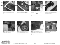
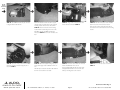
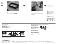
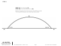
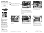
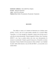
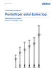
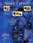
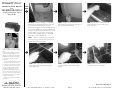
Stealthbox
®
INSTALLATION GUIDE
for the
SB-F-EXPDCNSL/10W3v2
(2003-Up Ford Expedition, without
AdvanceTrac®)
START
HERE
➔
➔
*Caution* You may be working on a Expedition
that has side air bags, located in the front seats.We
do ask for the removal of these front seats.
Disconnect the negative side of the battery and leave
for 15min.This will allow for discharge of the air bags.
Once the air bag wires have been disconnect, do not
turn the ignition on. If you do, the computer will
present an air bag fault.You may try to accomplish
this install, by not removing this seat.
➔
STEP 2: Using an 8mm socket, remove the
pair of bolts that are located on both sides of
the enclosure, towards the rear.
STEP 3: In the center console, remove the
rubber liner. Using a 7mm socket, remove
these four bolts.
STEP 1: Using a T-55 socket, unbolt the passenger side
front seat. Lean the seat back and disconnect the wire harness, this does include the air bag wire.
This Stealthbox is a product which
requires professional installation skills and
tools.
Please read this installation guide thoroughly before beginning the project. It
will guide you step by step through the
installation. Several of the steps in this
process may require two people to
accomplish.
It is absolutely vital that the enclosure
be properly mounted to the vehicle
according to these instructions. Failure
to mount the enclosure properly presents two problems: 1) The sub-bass
performance will suffer due to the
movement of the enclosure caused by
the force exerted by the woofer(s) and
2) A loose enclosure presents a serious
safety hazard in the event of a collision
or sudden deceleration.
Please enjoy your JL Audio Stealthbox
responsibly.
➔
➔
STEP 4: With a screwdriver remove the four
screws that are found around the top edge of
the storage bucket.
➔
STEP 5: Using a T-20 socket, remove the pair
of bolts at the top corners of the storage
bucket.
STEP 6: With a screwdriver, remove the six
screws that secure the console lid.
Continued on Next Page ➔
www.jlaudio.com
S B - F - E X P D C N S L / 1 0 W 3 v 2 , J L AU D I O, I n c 2 0 0 4
Pa g e 1
S h e e t S K U # 0 1 1 1 0 6 R ev i s i o n 6 / 3 0 / 2 0 0 4
Cont.
From
Previous
Page
➔
➔
STEP 7: Pull up and remove the cup holders.
➔
STEP 8: Using a 10mm socket, remove e the bolt
that secures the wire harness. Also remove the pair
of bolts that secure the console to the floor.
Using a 7mm socket, remove the pair of bolts that
have been exposed.
➔
STEP 11: As the console is tilted up, there are
more wiring harness that are exposed and that need
to be disconnected.
➔
STEP 9: Once the wire harness is unsecured, disconnect the white plug.
➔
STEP 12: With the console out of the Expedition,
pull down the rear cup holders. Us e a 7mm bolts
that have been exposed.
STEP 10: Tilt the console up from the rear.This
will expose another harness with a white plug., disconnect.
➔
STEP 13: Using a 17mm socket, remove the bolts
that secure the outside walls to the inner black console.
STEP 14: With the outside wall removed, lay the
console on its side. Using a 7mm socket, unsecured
and remove the wiring harness.
This now should allow the center console to be fully
removed out of the Expedition.
Continued on Next Page ➔
www.jlaudio.com
S B - F - E X P D C N S L / 1 0 W 3 v 2 , J L AU D I O, I n c 2 0 0 4
Pa g e 2
S h e e t S K U # 0 1 1 1 0 6 R ev i s i o n 6 / 3 0 / 2 0 0 4
Cont.
From
Previous
Page
➔
➔
STEP 15: Cut out the template that is found on
Page 6. Place this template across the rear portion
of the black inner console. Mark the correct scribe
lines.
➔
STEP 16: Scribe cut lines on the front portion of
the black inner console. Using the picture as a guide.
Same side as the scribe lines from STEP 15.
➔
STEP 17: Cut the black inner console, following
the scribe lines. A jig saw, air saw or cutting wheel
can be used.
STEP 18: With the rear portion of the black console, now modified. Place the supplied pair of washers, tucked in the corners. Mark washer’s inner holes
and then remove the washers.
*Hint*
It is easier to cut across the console, then cut the
arch.
➔
STEP 19: With a drill and 1/2” drill bit, drill holes
at marked location of the washers.
➔
STEP 20: Using the supplied hardware of (2) 3/8”16 x 1” hex bolts, (2) 3/8” flat washers and (2) lock
washers. Attach this drilled out position of the black
console, to the rear of the enclosure.
➔
STEP 21: Using the a supplied 3/8”-16x1” hex
bolt, 3/8”flat washer and 3/8”lock washer. Secure the
supplied L-bracket to the rear of the enclosure.The
longer length of the L-bracket mounts to the enclosure.
STEP 22: Remove the OEM console bracket, that
is mounted to the floor.
Continued on Next Page ➔
www.jlaudio.com
S B - F - E X P D C N S L / 1 0 W 3 v 2 , J L AU D I O, I n c 2 0 0 4
Pa g e 3
S h e e t S K U # 0 1 1 1 0 6 R ev i s i o n 6 / 3 0 / 2 0 0 4
Cont.
From
Previous
Page
➔
➔
STEP 23: Use a OEM bolt that was just removed
to plug the driver’s side bolt hole.
➔
At this time double check the woofer for proper
operation. Also run speaker wire to the enclosures
mounting location and connect to the terminal.
➔
STEP 25: Using a 7mm socket, secure the wire
harness that was removed in STEP14.
STEP 26: Place the front portion of the modified
black inner console, in front of the enclosure.
Route the wire harness under the driver’s side of
the enclosure and to the inside of the rear mounting
bracket.
STEP 24: Place the enclosure in the mounting
location. With L-bracket facing to the front of the
Expedition. Use the other OEM bolt that was
removed in STEP 22. Secure the L-bracket to the
floor.
➔
STEP 27: Secure the front portion of the modified
black inner console to the dash, using the pair of
bolts from STEP 7.
➔
STEP 28: Attach the suppled backing loop tape to
both bottom edges of the modified back inner console.
This will help to reduce the vibration rattle between
the inner console and the outer walls.
➔
STEP 29: Secure the outer walls to the enclosure
and the modified black inner console.
STEP 30: Secure the rear outer console, from
STEP 12.
Use the supplied (2)#6-32x1/2” pan head screws
and (2)#6x3/8” flat washers to secure the outer
walls’ top mounting tabs to the enclosure.
Continued on Next Page ➔
www.jlaudio.com
S B - F - E X P D C N S L / 1 0 W 3 v 2 , J L AU D I O, I n c 2 0 0 4
Pa g e 4
S h e e t S K U # 0 1 1 1 0 6 R ev i s i o n 6 / 3 0 / 2 0 0 4
Cont.
From
Previous
Page
➔
➔
STEP 31: Taking the factory storage bucket, Cut to
allow for a new depth of only 3-1/8”, from the top
edge.
➔
Included Hardware:
(3) 3/8”-16x1” Hex Bolts
(3) 3/8” Split Lock Washers
(3) 3/8” Flat Washers
(2) #6-32x1/2” Pan Head Screws
(2) #6x3/8” Flat Washers
(1) Metal L-Bracket
(1.1yd.) Backing Loop Tape
STEP 32: Secure the storage lid from STEP 6
and front passenger seat if you did remove.
*If you did remove the passenger’s front seat, reconnect all the wiring and then reconnect the battery’s
negative wire.*
Secure into the console, from STEPS 4&5.
CONGRATULATIONS!
INSTALL COMPLETE.
Difficulty Of Installation:
Mid/High Frequency Driver Information:
Specifications:
Enclosure Type: Acoustic Suspension (Sealed)
Driver Type: 10W3v2-D2
Nominal Impedance: 4Ω
Cont. Power Handling: 300Watts
Front Location Driver Size:
5” x 7”/6” x 8”
JL Audio recommends using a high quality amplifier such as the JL Audio 250/1. The diagram below shows the recommended
crossover, infrasonic filter and equalizer settings for the 250/1 when being used to power your Stealthbox®.
+12VDC
Ground
Remote
Preamp Output Section
Bass Control Amp LP Filter
Amplifier Input Section
Output Mode
Infrasonic Filter
Mode/Slope
Input Voltage
Full-Range/Low-Pass/High-Pass
Off/30Hz
Off/12dB/24dB
Low/High
Input Sens.
Signal Sensing
Off/On
+7
+3
+1
JL AUDIO 250/1
+10
+13
monoblock subwoofer amplifier
Left Ch.
Right Ch.
LF Boost (dB)
Filter Freq. (Hz)
ZR570-CSi
Applicable JL Audio Products:
ZR,XR,VR,TR570-CSi
Left Ch.
Rear Location Driver Size:
5” x 7”/6” x 8”
Applicable JL Audio Products:
N/A,
For proper installation, spacer rings are
required.
Right Ch.
The JL Audio 250/1 is a very versatile audio component. Please consult the owner’s manual for detailed information
about installing and tuning this amplifier.
10369 N. Commerce Pkwy, Miramar, Florida 33025-392
www.jlaudio.com
S B - F - E X P D C N S L / 1 0 W 3 v 2 , J L AU D I O, I n c 2 0 0 4
Phone: 954.443.1100
Pa g e 5
Fax: 954.443.1111
S h e e t S K U # 0 1 1 1 0 6 R ev i s i o n 6 / 3 0 / 2 0 0 4
STEP 15:
STEP 15(1): Cut straight edge, (A)
STEP 15(2): Cut on the outside of the arch, (B)
Position this template with the arch to the rear of the OEM inner console.
The marking of left and right is your left and right, not the vehicles.
(B)
right side
left side
(A)
www.jlaudio.com
(A)
S B - F - E X P D C N S L / 1 0 W 3 v 2 , J L AU D I O, I n c 2 0 0 4
Pa g e 6
S h e e t S K U # 0 1 1 1 0 6 R ev i s i o n 6 / 3 0 / 2 0 0 4