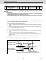
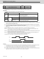
1
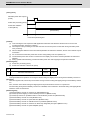
Introduction
This manual describes the various signal interfaces and functions required when creating MITSUBISHI CNC M800/
M80 Series sequence programs (built-in PLC).
Read this manual thoroughly before programming. Thoroughly study the "Safety Precautions" on the following page
to ensure safe use of this NC unit.
Details described in this manual
CAUTION
For items described as "Restrictions" or "Usable State" in this manual, the instruction manual issued by
the machine tool builder takes precedence over this manual.
Items that are not described in this manual must be interpreted as "not possible".
This manual is written on the assumption that all optional functions are added. Confirm the specifications
issued by the machine tool builder before use.
Some screens and functions may differ or may not be usable depending on the NC version.
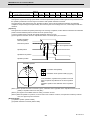
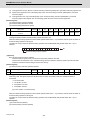
Precautions for Safety
Always read the specifications issued by the machine maker, this manual, related manuals and attached
documents before installation, operation, programming, maintenance or inspection to ensure correct use.
Understand this numerical controller, safety items and cautions before using the unit.This manual ranks the safety
precautions into "DANGER", "WARNING" and "CAUTION".
DANGER
When the user could be subject to imminent fatalities or major injuries if handling is mistaken.
WARNING
When the user could be subject to fatalities or major injuries if handling is mistaken.
CAUTION
When the user could be subject to minor or moderate injuries or the property could be damaged if handling
is mistaken.
Note that even items ranked as "
CAUTION", may lead to major results depending on the situation. In any case,
important information that must always be observed is described.
The following sings indicate prohibition and compulsory.
This sign indicates prohibited behavior (must not do).
For example,
indicates "Keep fire away".
This sign indicated a thing that is pompously (must do).
For example,
indicates "it must be grounded".
The meaning of each pictorial sing is as follows.
CAUTION
CAUTION rotated
object
CAUTION HOT
Danger Electric shock
risk
Danger explosive
Prohibited
Disassembly is
prohibited
KEEP FIRE AWAY
General instruction
Earth ground
For Safe Use
Mitsubishi CNC is designed and manufactured solely for applications to machine tools to be used for industrial
purposes.
Do not use this product in any applications other than those specified above, especially those which are
substantially influential on the public interest or which are expected to have significant influence on human lives or
properties.
DANGER
There are no "Danger" items in this manual.
WARNING
1. Items related to prevention of electric shocks
Do not operate the switches with wet hands, as this may lead to electric shocks.
Do not damage, apply excessive stress, place heavy things on or sandwich the cables, as this may lead to
electric shocks.
CAUTION
1. Items related to product and manual
For items described as "Restrictions" or "Usable State" in this manual, the instruction manual issued by
the machine tool builder takes precedence over this manual.
Items not described in this manual must be interpreted as "not possible".
This manual is written on the assumption that all optional functions are added. Confirm the specifications
issued by the machine tool builder before use.
Some screens and functions may differ or may not be usable depending on the NC system version.
2. Items related to connection
When using an inductive load such as relays, always contact a diode in parallel to the load as a noise
measure.
When using a capacitive load such as a lamp, always connect a protective resistor serially to the load to
suppress rush currents.
Since the analog output R registers are allocated in ascending order of channels and station numbers, the
analog output destination may change depending on added option.
3. Items related to design
Always turn the spindle phase synchronization completion signal ON before chucking both ends of the
workpiece to the basic spindle and synchronous spindle. If the spindle phase synchronization signal is
turned ON when both ends of the workpiece are chucked to the basic spindle and synchronous spindle, the
chuck or workpiece could be damaged by the torsion that occurs during phase alignment.
If the temperature rise detection function is invalidated with the parameters, the control could be disabled
when the temperature is excessive. This could result in machine damage or personal injuries due to
runaway axis, and could damage the device. Enable the detection function for normal use.
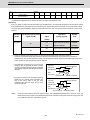
Disposal
(Note)
This symbol mark is for EU countries only.
This symbol mark is according to the directive 2006/66/EC Article 20 Information for endusers and Annex II.
Your MITSUBISHI ELECTRIC product is designed and manufactured with high quality materials and
components which can be recycled and/or reused.
This symbol means that batteries and accumulators, at their end-of-life, should be disposed of
separately from your household waste.
If a chemical symbol is printed beneath the symbol shown above, this chemical symbol means that the
battery or accumulator contains a heavy metal at a certain concentration. This will be indicated as
follows:
Hg: mercury (0,0005%), Cd: cadmium (0,002%), Pb: lead (0,004%)
In the European Union there are separate collection systems for used batteries and accumulators.
Please, dispose of batteries and accumulators correctly at your local community waste collection/
recycling centre.
Please, help us to conserve the environment we live in!
Trademarks
MELDAS, MELSEC, EZSocket, EZMotion, iQ Platform, MELSOFT, GOT, CC-Link, CC-Link/LT and CC-Link
IE are either trademarks or registered trademarks of Mitsubishi Electric Corporation in Japan and/or other
countries.
Ethernet is a registered trademark of Xerox Corporation in the United States and/or other countries.
Microsoft® and Windows® are either trademarks or registered trademarks of Microsoft Corporation in the
United States and/or other countries.
SD logo and SDHC logo are either registered trademarks or trademarks of LLC.
UNIX is a registered trademark of The Open Group in the United States and/or other countries.
Intel® and Pentium® are either trademarks or registered trademarks of Intel Corporation in the United States
and/or other countries.
MODBUS® is either trademark or registered trademark of Schneider Electric USA, Inc. or the affiliated
companies in Japan and/or other countries.
Other company and product names that appear in this manual are trademarks or registered trademarks of the
respective companies.
本製品の取扱いについて
( 日本語 /Japanese)
本製品は工業用 ( クラス A) 電磁環境適合機器です。販売者あるいは使用者はこの点に注意し、住商業環境以外で
の使用をお願いいたします。
Handling of our product
(English)
This is a class A product. In a domestic environment this product may cause radio interference in which case the
user may be required to take adequate measures.
본 제품의 취급에 대해서
( 한국어 /Korean)
이 기기는 업무용 (A 급 ) 전자파적합기기로서 판매자 또는 사용자는 이 점을 주의하시기 바라며 가정외의 지역에
서 사용하는 것을 목적으로 합니다 .
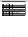
Contents
1 List of Devices.............................................................................................................................................. 1
1.1 List of Devices......................................................................................................................................................... 2
1.1.1 Device Range Setting at Multi-projects ........................................................................................................ 3
1.2 File Register General Map ...................................................................................................................................... 5
2 Input/Output Signals with Controller ......................................................................................................... 7
2.1 PLC Input Signals (Bit type: X***) ........................................................................................................................ 10
2.2 PLC Input Signals (Data type: R***)..................................................................................................................... 37
2.3 PLC Output Signals (Bit type: Y***) ..................................................................................................................... 73
2.4 PLC Output Signals (Data type: R***)................................................................................................................ 100
2.5 Special Relay/Register........................................................................................................................................ 145
2.6 ZR Devices........................................................................................................................................................... 151
2.7 Classified for Each Application ......................................................................................................................... 156
3 Other Devices ........................................................................................................................................... 165
4 Explanation of Interface Signals............................................................................................................. 169
4.1 PLC Input Signals (Bit Type: X***) ..................................................................................................................... 170
4.2 PLC Input Signals (Data Type: R***).................................................................................................................. 278
4.3 PLC Output Signals (Bit Type: Y***) .................................................................................................................. 352
4.4 PLC Output Signals (Data Type: R***)............................................................................................................... 530
4.5 Explanation of Special Relays (SM***) .............................................................................................................. 627
4.6 Explanation of ZR device ................................................................................................................................... 628
4.6.1 PLC → CNC ................................................................................................................................................. 628
4.6.2 CNC → PLC ................................................................................................................................................. 647
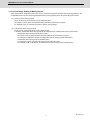
1
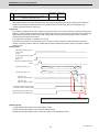
List of Devices
1
IB-1501272-B
M800/M80 Series PLC Interface Manual
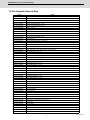
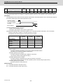
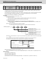
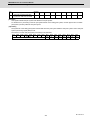
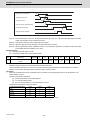
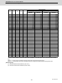
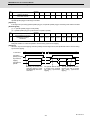
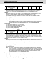
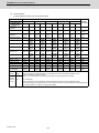
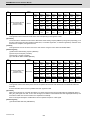
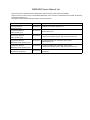
1 List of Devices
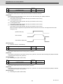
1.1 List of Devices
Device
Device No.
Unit
Details
X*
X0 to X1FFF (8192 points)
1 bit
Input signal to PLC: Machine input, etc.
Y*
Y0 to Y1FFF (8192 points)
1 bit
Output signal from PLC: Machine output, etc.
M
M0 to M61439 (61440 points)
1 bit
Temporary memory
F
F0 to F2047 (2048 points)
1 bit
Temporary memory.
Alarm message interface
Latch relay (back up memory)
L
SM
V
SB
L0 to L1023 (1024 points)
1 bit
SM0 to SM2047 (2048 points)
1 bit
Special relay
V0 to V511 (512 points)
1 bit
Edge relay
SB0 to SB3FF (1024points)
1 bit
Special relay
B
B0 to BDFFF (57344 points)
1 bit
Link relay
SW
SW0 to SW3FF (1024points)
1 bit
Special register
SD
SD0 to SD2047 (2048 points)
16 bit
Special register
T
ST
Timer
(The variable/fixed boundary is set with a parameter.)
(Note 2)
T0 to T2047 (2048 points)
1 bit/16 bit
ST0 to ST127
1 bit/16 bit
Integrated timer (100ms unit)
1 bit/16 bit
Counter (The variable/fixed boundary is set with a
parameter.)
C
C0 to C511
(128 points)
(512 points)
D
D0 to D4095 (4096 points)
16 bit/32 bit
Data register. Register for calculation
R*
R0 to R32767 (32768 points)
16 bit/32 bit
File register. CNC word interface
ZR
ZR0 to ZR13311 (13312
points)
16 bit/32 bit
File register
W
W0 to W2FFF (12288 points)
16 bit/32 bit
Link register
Z
Z0 to Z13
(14 points)
16 bit
Address index
N
N0 to N14
(15 points)
-
P*
P0 to P4095
(4096 points)
-
Label for conditional jump, subroutine call command
K-32768 to K32767
-
Decimal constant for 16-bit command
K-2147483648
to K2147483647
-
Decimal constant for 32-bit command
H0 to HFFFF
-
Hexadecimal constant for 16-bit command
H0 to HFFFFFFFF
-
Hexadecimal constant for 32-bit command
K
H
Master controller nesting level
(Note 1) Devices marked with * in the device column have designated applications. Do not use devices other than
those corresponding to the input/output signals with the machine side (input/output signals of the remote I/O
unit), even if it is an undefined vacant device.
(Note 2) Distinction of 10ms timer and 100ms timer is performed by command.
(10ms timer is performed by OUTH command, 100ms timer is performed by OUT command.)
IB-1501272-B
2
M800/M80 Series PLC Interface Manual
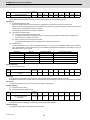
1 List of Devices
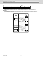
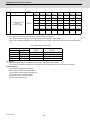
1.1.1 Device Range Setting at Multi-projects
Each device will be categorized to either the common device among projects (common device among projects) or the
independent device for each projects (independent device among projects) when using the multi-project function.
(a)
Common device among projects
Device is influenced by the access from the multiple projects.
The number of device points is fixed without being affected by the number of projects.
For example, the X/ Y/ R devices are common devices among projects.
(b)
Independent device among projects
Device can be used independently in the multiple projects.
In addition, Independent device among projects are categorized into variable points or fixed points device.
- Independent device among projects (Fixed points)
The number of device points is fixed without being affected by the number of projects.
For example, the SM/ SD/ Z devices are independent devices among projects (fixed points)
- Independent device among projects (Variable points)
The maximum number of project is allocated to each project and used.
For example, the M/ L/ SB devices are independent devices among projects (variable points)
3
IB-1501272-B
M800/M80 Series PLC Interface Manual
1 List of Devices
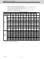
The list of device categories is as follows.
(1) Category explanation
Category
Details
Common
Common device among projects
Independent (fixed)
Independent device among projects (fixed points)
Independent (variable)
Independent device among projects (variable points)
Common/independent
Independent device among projects (variable points)
However, it is possible to set as the common device among projects from the top.
(2) List of categories
Device
Number of device points
(Maximum number of
projects)
Category
X
Common
8192 points
Y
Common
8192 points
M
Common/Independent
61440 points (122880 points)
L
Independent(Variable)
1024 points (2048 points)
F
Common
2048 points
SB
Independent(Variable)
1024 points (2048 points)
57344 points (114688 points)
B
Independent(Variable)
SM
Independent(Fixed)
2048 points
V
Independent(Variable)
256 points (1024 points)
SW
Independent(Variable)
1024 points (2048 points)
SD
Independent(Fixed)
2048 points
T
Independent(Variable)
2048 points (4096 points)
ST
Independent(Variable)
128 points (256 points)
C
Independent(Variable)
512 points (1024 points)
D
Common/Independent
4096 points (8192 points)
R
Common
32768 points
ZR
Common
13312 points
W
Independent(Variable)
12288 points (24576 points)
Z
Independent(Fixed)
14 points
N
Independent(Fixed)
15 points
P
Independent(Fixed)
4096 points
* Number of points in brackets is for the options.
Refer to "PLC Programming Manual" for details on the independent device among projects and the common device
among projects.
IB-1501272-B
4
M800/M80 Series PLC Interface Manual
1 List of Devices
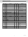
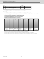
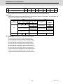
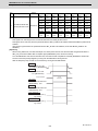
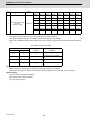
1.2 File Register General Map
Device
R00000 to R00199
Details
System common data (NC -> PLC)
R00200 to R00499
System common data (PLC -> NC)
R00500 to R00699
1st part system data (NC -> PLC)
R00700 to R00899
2nd part system data (NC -> PLC)
R00900 to R01099
3rd part system data (NC -> PLC)
R01100 to R01299
4th part system data (NC -> PLC)
R01300 to R02099
System reserve
R02100 to R02397
Pallet program data (Drive unit -> PLC)
R02500 to R02699
1st part system data (PLC -> NC)
R02700 to R02899
2nd part system data (PLC -> NC)
R02900 to R03099
3rd part system data (PLC -> NC)
R03100 to R03299
4th part system data (PLC -> NC)
R03300 to R04099
System reserve
R04100 to R04103
Pallet program data (PLC -> Drive unit)
R04104 to R04499
System reserve
R04500 to R05683
Axis data (NC -> PLC)
R05684 to R05699
System reserve
R05700 to R06371
Axis data (PLC -> NC)
R06372 to R06499
User macro (NC -> PLC: 64 point, PLC -> NC: 64 point)
R06500 to R06549
1st spindle data (NC -> PLC)
R06550 to R06599
2nd spindle data (NC -> PLC)
R06600 to R06649
3rd spindle data (NC -> PLC)
R06650 to R06699
4th spindle data (NC -> PLC)
R06700 to R06749
5th spindle data (NC -> PLC)
R06750 to R06799
6th spindle data (NC -> PLC)
R06800 to R06849
7th spindle data (NC -> PLC)
R06850 to R06899
8th spindle data (NC -> PLC)
R06900 to R06999
System reserve
R07000 to R07049
1st spindle data (PLC -> NC)
R07050 to R07099
2nd spindle data (PLC -> NC)
R07100 to R07149
3rd spindle data (PLC -> NC)
R07150 to R07199
4th spindle data (PLC -> NC)
R07200 to R07249
5th spindle data (PLC -> NC)
R07250 to R07299
6th spindle data (PLC -> NC)
R07300 to R07349
7th spindle data (PLC -> NC)
R07350 to R07399
8th spindle data (PLC -> NC)
R07400 to R07499
System reserve
R07500 to R07949
PLC constants
R07950 to R07999
System reserve
R08000 to R08099
PLC axis indexing
R08100 to R08289
System reserve
R08290 to R08299
Optimum acceleration/deceleration (Spindle)
R08300 to R09799
User backed up area
R09800 to R09899
User work area
R09900 to R09999
J2CT
R10000 to R10099
Remote I/O communication error information
R10100 to R10139
I/O link input
R10140 to R10179
I/O link output
R10180 to R10180
I/O link communication status
R10181 to R10187
System reserve
R10188 to R10189
Base PLC mounting check
R10190 to R10199
MELSEC link II diagnosis I/F
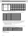
5
IB-1501272-B
M800/M80 Series PLC Interface Manual
1 List of Devices
Device
Details
R10200 to R10399
Data buffer for MELSEC link II (machine input)
R10400 to R10599
Data buffer for MELSEC link II (machine output)
R10600 to R12759
ATC data, tool life management for M system / Tool life management I, II for L system
R12760 to R13999
System reserve
R14000 to R14499
EcoMonitorLight data (NC -> PLC)
R14500 to R17299
System reserve
R17300 to R18299
Modbus input/output device
R18300 to R19799
User backup area
R19800 to R19899
User work area
R19900 to R19999
System reserve
R20000 to R20199
System common data (NC -> PLC)
R20200 to R20499
System common data (PLC -> NC)
R20500 to R20699
1st part system data (NC -> PLC)
R20700 to R20899
2nd part system data (NC -> PLC)
R20900 to R21099
3rd part system data (NC -> PLC)
R21100 to R21299
4th part system data (NC -> PLC)
R21300 to R22499
System reserve
R22500 to R22699
1st part system data (PLC -> NC)
R22700 to R22899
2nd part system data (PLC -> NC)
R22900 to R23099
3rd part system data (PLC -> NC)
R23100 to R23299
4th part system data (PLC -> NC)
R23300 to R28299
System reserve
R28300 to R29799
User backup area
R29800 to R29899
User work area
R29900 to R32767
System reserve
(Note)
IB-1501272-B
The system reserve is used for function expansion by Mitsubishi, and must not be used by the user.
6
2
Input/Output Signals
with Controller
7
IB-1501272-B
M800/M80 Series PLC Interface Manual
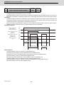
2 Input/Output Signals with Controller
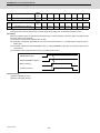
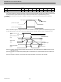
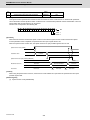
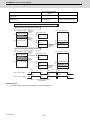
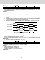
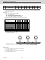
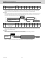
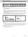
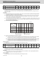
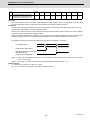
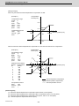
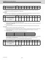
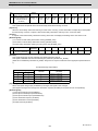
Types of Input/Output Signals Tables
The followings are the types of input/output signals tables to be used.
For common devices used in part systems (Sample)
Device
Abbrev.
Signal name
Device
X720
Signal name
Abbrev.
X728
X721
X729
X722
Diagnosis data output completio
X72A
X723
Collecting diagnosis data
X72B
X724
X725
▲ X72C
In remote program input
Remote program input completion▲ X72D
X726
Remote program input error
X727
In tool ID communication
▲ X72E
▲▲ X72F
Power OFF required after parameter change
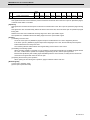
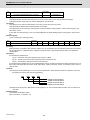
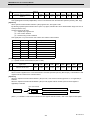
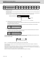
For devices used in each part system (Sample)
Device No.
$1
$2
$3
$4
Abbrev.
Signal name
Y7A0
Y7A8
Y7B0
Y7B8
*SVF1
Servo OFF 1st axis
Y7A1
Y7A9
Y7B1
Y7B9
*SVF2
2st axis
Y7A2
Y7AA
Y7B2
Y7BA
*SVF3
3st axis
Y7A3
Y7AB
Y7B3
Y7BB
*SVF4
4st axis
Y7A4
Y7AC
Y7B4
Y7BC
*SVF5
5st axis
Y7A5
Y7AD
Y7B5
Y7BD
*SVF6
6st axis
Y7A6
Y7AE
Y7B6
Y7BE
*SVF7
7st axis
Y7A7
Y7AF
Y7B7
Y7BF
*SVF8
8st axis
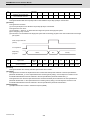
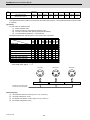
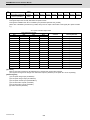
For devices used in each spindle (Sample)
&GXKEG0Q 1stSP 2stSP
3stSP
4stSP
5stSP
6stSP
Abbrev.
Signal name
R6500
R6550
R6600
R6650
R6700
R6750
Spindle command rotation speed input
R6501
R6551
R6601
R6651
R6701
R6751
(H)
R6502
R6552
R6602
R6652
R6702
R6752
Spindle command final data (rotation speed) (L)
R6503
R6553
R6603
R6653
R6703
R6753
(H)
R6504
R6554
R6604
R6654
R6704
R6754
Spindle command final data (12-bit binary) (L)
R6505
R6555
R6605
R6655
R6705
R6755
R6506
R6556
R6606
R6656
R6706
R6756
R6507
R6557
R6607
R6657
R6707
R6757
(L)
) (H)
Spindle actual speed
(L)
(H)
(Note 1) Signals marked with "*" in the "Abbrev." column are handled as B contacts.
(Note 2) Signals marked with " ▲ " are prepared for a specific machine tool builder.
(Note 3) Unit is changed by "#1040 M_inch" for the signals marked with [M].
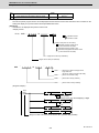
(Note 4) 32bit signals are shown with (L)/(H), which indicates Low/High order. Data structure and the descriptions are
as follows.
IB-1501272-B
Rn
Low-order (L)
Rn+1
High-order (H)
8
M800/M80 Series PLC Interface Manual
2 Input/Output Signals with Controller
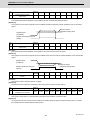
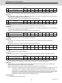
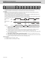
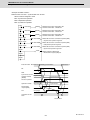
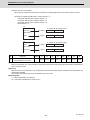
Classification of Input/Output Signals with Controller
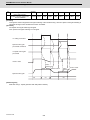
There are 1-bit unit, and 16-bit or 32-bit unit controller input/output signals, which are classified as shown below.
When designing, refer to the section indicated below and make allocations according to the table in the respective
section.
"$" and "SP" in "Device No." column stand for "part system" and "spindle" respectively.
Signal type
Reference
DI
Data
(1) Allocated to device R.
(2) Data handled in 16-bit or 32-bit units is allocated as a
principle.
DO
(1) Allocated to device Y.
(2) Data calculated in bit units are allocated as a principle.
"PLC Output Signals (Bit Type: Y***)"
(3) Signals with only $1 or 1stSP section filled are common for
all part systems or all spindles.
Data
(1) Allocated to device R.
(2) Data handled in 16-bit or 32-bit units is allocated as a
principle.
Special relay/
register
(1) Allocated to device SM, SB and SW.
(2) The sequence instruction calculation state, results and the "Explanation of Special Relays/Register"
signals with special operations are allocated.
ZR
(1) Allocated to device ZR.
(2) Use in the smart safety observation function.
"ZR device"
Classified under
purpose
Devices are classified under the usage purpose.
"Explanations for Each Application"
Input
Output
Others
Explanation
(1) Allocated to device X.
(2) Data calculated in bit units are allocated as a principle.
"PLC Input Signals (Bit Type: X***)"
(3) Signals with only $1 or 1stSP section filled are common for
all part systems or all spindles.
9
"PLC Input Signals (Data Type: R***)"
"PLC Output Signals (Data Type: R***)"
IB-1501272-B
M800/M80 Series PLC Interface Manual
2 Input/Output Signals with Controller
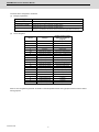
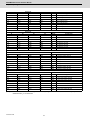
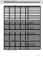
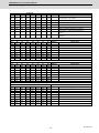
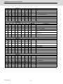
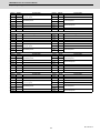
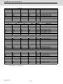
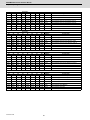
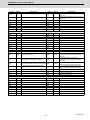
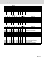
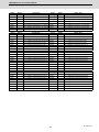
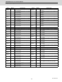
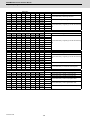
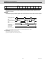
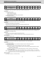
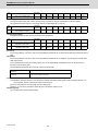
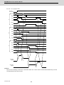
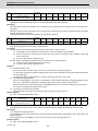
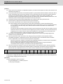
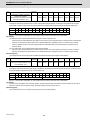
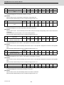
2.1 PLC Input Signals (Bit type: X***)
(Note) Signals with " ▲ " are prepared for specific machine tool builders.
Device
X2F0
Abbrev.
BRST
Device
Abbrev.
Signal name
Device
Abbrev.
Signal name
Device
Abbrev.
Signal name
Board reset
Signal name
X700
IPCEI1
Power consumption computation:
Consumption accumulation ON 1
X708
IPCCC1
Power consumption computation:
Clearing consumption accumulation 1
complete
X701
IPCEI2
Power consumption computation:
Consumption accumulation ON 2
X709
IPCCC2
Power consumption computation:
Clearing consumption accumulation 2
complete
X702
IPCEI3
Power consumption computation:
Consumption accumulation ON 3
X70A
IPCCC3
Power consumption computation:
Clearing consumption accumulation 3
complete
X703
IPCEI4
Power consumption computation:
Consumption accumulation ON 4
X70B
IPCCC4
Power consumption computation:
Clearing consumption accumulation 4
complete
X704
X70C
X705
X70D
X706
X707
Power OFF processing
Device
Abbrev.
X70E
BATWR
Battery warning
X70F
BATAL
Battery alarm
Signal name
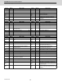
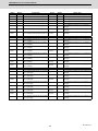
Device
X710
X718
X711
Optimum acceleration/deceleration
X719
switching parameter completion [spindle] ▲
X712
SMLKO
High-speed simple program check mode ON X71A
X713
SPSCO
High-speed simple program check:
Coordinate position check ON
X71B
X715
PCHKO
Manual arbitrary reverse run mode ON
X71D
X716
MOREV
Manual arbitrary reverse run: Reverse run ON X71E
X714
Abbrev.
Signal name
Abbrev.
Signal name
X71C
X717
Device
X71F
Abbrev.
X720
Signal name
In sampling trace
X721
Sampling trace complete
X722
Diagnosis data output completion
X723
Collecting diagnosis data
X724
In remote program input
X725
Remote program input completion
X726
Remote program input error
X727
In tool ID communication
Device
Abbrev.
Device
▲ X728
MDBUSIF Modbus/TCP communicating
▲
▲ X729
MDBUSE
Modbus time-out 1
R1
▲
X72A
MDBUSE
Modbus time-out 2
R2
▲
X72B
FLNETO FL-net : Online
▲
▲ X72C
▲ X72D
▲ X72E
▲ X72F
Signal name
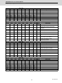
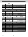
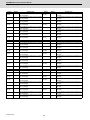
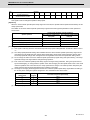
Device
X730
X738
X731
X739
X732
X73A
X733
X73B
X734
X73C
X735
X73D
X736
X73E
X737
X73F
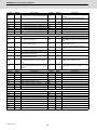
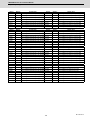
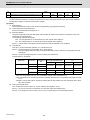
IB-1501272-B
10
Power OFF required after parameter change
Abbrev.
Signal name
M800/M80 Series PLC Interface Manual
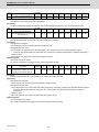
2 Input/Output Signals with Controller
Device
Abbrev.
Signal name
Device
Abbrev.
Signal name
X740
X748
X741
X749
X742
X74A
X743
X74B
X744
X74C
X745
X74D
MBSTP
Thread, tap block stopping in manual arbitrary
reverse run
X746
X74E
MRVNG
Thread, tap reverse run prohibition alarm in
manual arbitrary reverse run
X747
X74F
Device
Abbrev.
Signal name
X750
Device
X759
X752
CNOP
24 hours continuous operation
X753
MSOE
In multi-step speed monitor
X75A
X754
▲ X75B
X75C
X755
X75D
X756
X75E
X757
X75F
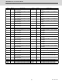
Abbrev.
Signal name
Device
X760
$1 Display
X768
X761
$2 Display
X769
X762
$3 Display
X76A
X763
$4 Display
X76B
X764
$5 Display
X76C
X765
$6 Display
X76D
X766
$7 Display
X76E
X767
$8 Display
X76F
Device
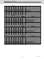
Signal name
Pallet program registration
Ext. workpiece coordinate transfer completion
X758
X751
Device
Abbrev.
Abbrev.
Signal name
Device
Abbrev.
Abbrev.
Signal name
Signal name
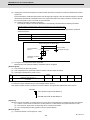
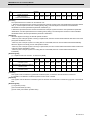
X770
X778
GBMOD
G/B spindle synchronizing mode
X771
X779
GBSYN
G/B spindle synchronization: position control
synchronizing
X772
X77A
GBPHF
G/B spindle synchronization: phase alignment
complete
X773
X77B
GBPCM
G/B spindle synchronization: position error
compensating
X774
X77C
X775
X77D
X776
X77E
X777
X77F
11
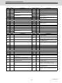
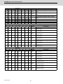
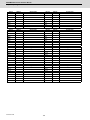
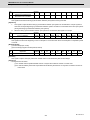
IB-1501272-B
M800/M80 Series PLC Interface Manual
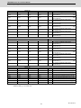
2 Input/Output Signals with Controller
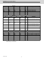
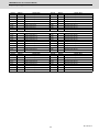
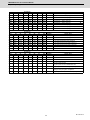
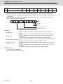
Device No.
$1
$2
$3
$4
Abbrev.
Signal name
X780
X788
X790
X798
RDY1
Servo ready 1st axis
X781
X789
X791
X799
RDY2
Servo ready 2nd axis
X782
X78A
X792
X79A
RDY3
Servo ready 3rd axis
X783
X78B
X793
X79B
RDY4
Servo ready 4th axis
X784
X78C
X794
X79C
RDY5
Servo ready 5th axis
X785
X78D
X795
X79D
RDY6
Servo ready 6th axis
X786
X78E
X796
X79E
RDY7
Servo ready 7th axis
X787
X78F
X797
X79F
RDY8
Servo ready 8th axis
Device No.
$1
$2
$3
$4
Abbrev.
Signal name
X7A0
X7A8
X7B0
X7B8
AX1
Axis selection 1st axis
X7A1
X7A9
X7B1
X7B9
AX2
Axis selection 2nd axis
X7A2
X7AA
X7B2
X7BA
AX3
Axis selection 3rd axis
X7A3
X7AB
X7B3
X7BB
AX4
Axis selection 4th axis
X7A4
X7AC
X7B4
X7BC
AX5
Axis selection 5th axis
X7A5
X7AD
X7B5
X7BD
AX6
Axis selection 6th axis
X7A6
X7AE
X7B6
X7BE
AX7
Axis selection 7th axis
X7A7
X7AF
X7B7
X7BF
AX8
Axis selection 8th axis
Device No.
$1
$2
$3
$4
Abbrev.
Signal name
X7C0
X7C8
X7D0
X7D8
MVP1
In axis plus motion 1st axis
X7C1
X7C9
X7D1
X7D9
MVP2
In axis plus motion 2nd axis
X7C2
X7CA
X7D2
X7DA
MVP3
In axis plus motion 3rd axis
X7C3
X7CB
X7D3
X7DB
MVP4
In axis plus motion 4th axis
X7C4
X7CC
X7D4
X7DC
MVP5
In axis plus motion 5th axis
X7C5
X7CD
X7D5
X7DD
MVP6
In axis plus motion 6th axis
X7C6
X7CE
X7D6
X7DE
MVP7
In axis plus motion 7th axis
X7C7
X7CF
X7D7
X7DF
MVP8
In axis plus motion 8th axis
Device No.
$1
$2
$3
$4
Abbrev.
Signal name
X7E0
X7E8
X7F0
X7F8
MVM1
In axis minus motion 1st axis
X7E1
X7E9
X7F1
X7F9
MVM2
In axis minus motion 2nd axis
X7E2
X7EA
X7F2
X7FA
MVM3
In axis minus motion 3rd axis
X7E3
X7EB
X7F3
X7FB
MVM4
In axis minus motion 4th axis
X7E4
X7EC
X7F4
X7FC
MVM5
In axis minus motion 5th axis
X7E5
X7ED
X7F5
X7FD
MVM6
In axis minus motion 6th axis
X7E6
X7EE
X7F6
X7FE
MVM7
In axis minus motion 7th axis
X7E7
X7EF
X7F7
X7FF
MVM8
In axis minus motion 8th axis
(Note)
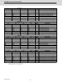
The CNC control and CNC status signals are arbitrarily assigned to the device and axis numbers by the parameter
"#1603 PLCdev_no" for each axis.
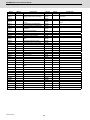
IB-1501272-B
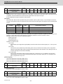
12
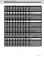
M800/M80 Series PLC Interface Manual
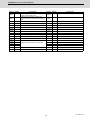
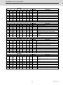
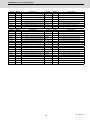
2 Input/Output Signals with Controller
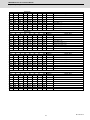
Device No.
$1
$2
$3
$4
Abbrev.
Signal name
X800
X808
X810
X818
ZP11
1st reference position reached 1st axis
X801
X809
X811
X819
ZP12
1st reference position reached 2nd axis
X802
X80A
X812
X81A
ZP13
1st reference position reached 3rd axis
X803
X80B
X813
X81B
ZP14
1st reference position reached 4th axis
X804
X80C
X814
X81C
ZP15
1st reference position reached 5th axis
X805
X80D
X815
X81D
ZP16
1st reference position reached 6th axis
X806
X80E
X816
X81E
ZP17
1st reference position reached 7th axis
X807
X80F
X817
X81F
ZP18
1st reference position reached 8th axis
Device No.
$1
$2
$3
$4
Abbrev.
Signal name
X820
X828
X830
X838
ZP21
2nd reference position reached 1st axis
X821
X829
X831
X839
ZP22
2nd reference position reached 2nd axis
X822
X82A
X832
X83A
ZP23
2nd reference position reached 3rd axis
X823
X82B
X833
X83B
ZP24
2nd reference position reached 4th axis
X824
X82C
X834
X83C
ZP25
2nd reference position reached 5th axis
X825
X82D
X835
X83D
ZP26
2nd reference position reached 6th axis
X826
X82E
X836
X83E
ZP27
2nd reference position reached 7th axis
X827
X82F
X837
X83F
ZP28
2nd reference position reached 8th axis
Device No.
$1
$2
$3
$4
Abbrev.
Signal name
X840
X848
X850
X858
ZP31
3rd reference position reached 1st axis
X841
X849
X851
X859
ZP32
3rd reference position reached 2nd axis
X842
X84A
X852
X85A
ZP33
3rd reference position reached 3rd axis
X843
X84B
X853
X85B
ZP34
3rd reference position reached 4th axis
X844
X84C
X854
X85C
ZP35
3rd reference position reached 5th axis
X845
X84D
X855
X85D
ZP36
3rd reference position reached 6th axis
X846
X84E
X856
X85E
ZP37
3rd reference position reached 7th axis
X847
X84F
X857
X85F
ZP38
3rd reference position reached 8th axis
Device No.
$1
$2
$3
$4
Abbrev.
Signal name
X860
X868
X870
X878
ZP41
4th reference position reached 1st axis
X861
X869
X871
X879
ZP42
4th reference position reached 2nd axis
X862
X86A
X872
X87A
ZP43
4th reference position reached 3rd axis
X863
X86B
X873
X87B
ZP44
4th reference position reached 4th axis
X864
X86C
X874
X87C
ZP45
4th reference position reached 5th axis
X865
X86D
X875
X87D
ZP46
4th reference position reached 6th axis
X866
X86E
X876
X87E
ZP47
4th reference position reached 7th axis
X867
X86F
X877
X87F
ZP48
4th reference position reached 8th axis
(Note)
The CNC control and CNC status signals are arbitrarily assigned to the device and axis numbers by the parameter
"#1603 PLCdev_no" for each axis.
13
IB-1501272-B
M800/M80 Series PLC Interface Manual
2 Input/Output Signals with Controller
Device No.
$1
$2
$3
$4
Abbrev.
Signal name
X880
X888
X890
X898
NRF1
Near reference position 1st axis
X881
X889
X891
X899
NRF2
Near reference position 2nd axis
X882
X88A
X892
X89A
NRF3
Near reference position 3rd axis
X883
X88B
X893
X89B
NRF4
Near reference position 4th axis
X884
X88C
X894
X89C
NRF5
Near reference position 5th axis
X885
X88D
X895
X89D
NRF6
Near reference position 6th axis
X886
X88E
X896
X89E
NRF7
Near reference position 7th axis
X887
X88F
X897
X89F
NRF8
Near reference position 8th axis
Device No.
$1
$2
$3
$4
Abbrev.
Signal name
X8A0
X8A8
X8B0
X8B8
PLFN1
Arbitrary axis superimposition complete 1st
axis
X8A1
X8A9
X8B1
X8B9
PLFN2
Arbitrary axis superimposition complete 2nd
axis
X8A2
X8AA
X8B2
X8BA
PLFN3
Arbitrary axis superimposition complete 3rd
axis
X8A3
X8AB
X8B3
X8BB
PLFN4
Arbitrary axis superimposition complete 4th
axis
X8A4
X8AC
X8B4
X8BC
PLFN5
Arbitrary axis superimposition complete 5th
axis
X8A5
X8AD
X8B5
X8BD
PLFN6
Arbitrary axis superimposition complete 6th
axis
X8A6
X8AE
X8B6
X8BE
PLFN7
Arbitrary axis superimposition complete 7th
axis
X8A7
X8AF
X8B7
X8BF
PLFN8
Arbitrary axis superimposition complete 8th
axis
Device No.
$1
$2
$3
$4
Abbrev.
Signal name
X8C0
X8C8
X8D0
X8D8
ZSF1
Zero point initialization set completed 1st axis
X8C1
X8C9
X8D1
X8D9
ZSF2
Zero point initialization set completed 2nd axis
X8C2
X8CA
X8D2
X8DA
ZSF3
Zero point initialization set completed 3rd axis
X8C3
X8CB
X8D3
X8DB
ZSF4
Zero point initialization set completed 4th axis
X8C4
X8CC
X8D4
X8DC
ZSF5
Zero point initialization set completed 5th axis
X8C5
X8CD
X8D5
X8DD
ZSF6
Zero point initialization set completed 6th axis
X8C6
X8CE
X8D6
X8DE
ZSF7
Zero point initialization set completed 7th axis
X8CF
X8D7
X8DF
ZSF8
Zero point initialization set completed 8th axis
X8C7
(Note)
The CNC control and CNC status signals are arbitrarily assigned to the device and axis numbers by the parameter
"#1603 PLCdev_no" for each axis.
IB-1501272-B
14
M800/M80 Series PLC Interface Manual
2 Input/Output Signals with Controller
Device No.
$1
$2
$3
$4
Abbrev.
Signal name
X8E0
X8E8
X8F0
X8F8
ZSE1
Zero point initialization set error completed 1st
axis
X8E1
X8E9
X8F1
X8F9
ZSE2
Zero point initialization set error completed 2nd
axis
X8E2
X8EA
X8F2
X8FA
ZSE3
Zero point initialization set error completed 3rd
axis
X8E3
X8EB
X8F3
X8FB
ZSE4
Zero point initialization set error completed 4th
axis
X8E4
X8EC
X8F4
X8FC
ZSE5
Zero point initialization set error completed 5th
axis
X8E5
X8ED
X8F5
X8FD
ZSE6
Zero point initialization set error completed 6th
axis
X8E6
X8EE
X8F6
X8FE
ZSE7
Zero point initialization set error completed 7th
axis
X8E7
X8EF
X8F7
X8FF
ZSE8
Zero point initialization set error completed 8th
axis
Device No.
$1
X900
$2
X908
$3
X910
$4
X918
Abbrev.
ILI1
Signal name
In current limit 1st axis
X901
X909
X911
X919
ILI2
In current limit 2nd axis
X902
X90A
X912
X91A
ILI3
In current limit 3rd axis
X903
X90B
X913
X91B
ILI4
In current limit 4th axis
X904
X90C
X914
X91C
ILI5
In current limit 5th axis
X905
X90D
X915
X91D
ILI6
In current limit 6th axis
X906
X90E
X916
X91E
ILI7
In current limit 7th axis
X907
X90F
X917
X91F
ILI8
In current limit 8th axis
Device No.
$1
X920
$2
$3
$4
X938
Abbrev.
ILA1
Signal name
X928
X930
Current limit reached 1st axis
X921
X929
X931
X939
ILA2
Current limit reached 2nd axis
X922
X92A
X932
X93A
ILA3
Current limit reached 3rd axis
X923
X92B
X933
X93B
ILA4
Current limit reached 4th axis
X924
X92C
X934
X93C
ILA5
Current limit reached 5th axis
X925
X92D
X935
X93D
ILA6
Current limit reached 6th axis
X926
X92E
X936
X93E
ILA7
Current limit reached 7th axis
X927
X92F
X937
X93F
ILA8
Current limit reached 8th axis
Device No.
$1
X940
$2
$3
X948
X950
X941
X949
X942
X94A
X943
X944
$4
Abbrev.
Signal name
X958
ARRF1
X951
X959
ARRF2
NC axis up-to-speed 2nd axis
X952
X95A
ARRF3
NC axis up-to-speed 3rd axis
X94B
X953
X95B
ARRF4
NC axis up-to-speed 4th axis
X94C
X954
X95C
ARRF5
NC axis up-to-speed 5th axis
X945
X94D
X955
X95D
ARRF6
NC axis up-to-speed 6th axis
X946
X94E
X956
X95E
ARRF7
NC axis up-to-speed 7th axis
X947
X94F
X957
X95F
ARRF8
NC axis up-to-speed 8th axis
(Note)
NC axis up-to-speed 1st axis
The CNC control and CNC status signals are arbitrarily assigned to the device and axis numbers by the parameter
"#1603 PLCdev_no" for each axis.
15
IB-1501272-B
M800/M80 Series PLC Interface Manual
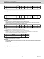
2 Input/Output Signals with Controller
Device No.
$1
$2
$3
$4
Abbrev.
Signal name
X960
X968
X970
X978
UCLP1
Unclamp command 1st axis
X961
X969
X971
X979
UCLP2
Unclamp command 2nd axis
X962
X96A
X972
X97A
UCLP3
Unclamp command 3rd axis
X963
X96B
X973
X97B
UCLP4
Unclamp command 4th axis
X964
X96C
X974
X97C
UCLP5
Unclamp command 5th axis
X965
X96D
X975
X97D
UCLP6
Unclamp command 6th axis
X966
X96E
X976
X97E
UCLP7
Unclamp command 7th axis
X967
X96F
X977
X97F
UCLP8
Unclamp command 8th axis
Device No.
$1
$2
X980
X988
$3
X990
$4
Abbrev.
X998
Signal name
In mixed control (cross axis control) 1st axis
X981
X989
X991
X999
In mixed control (cross axis control) 2nd axis
X982
X98A
X992
X99A
In mixed control (cross axis control) 3rd axis
X983
X98B
X993
X99B
In mixed control (cross axis control) 4th axis
X984
X98C
X994
X99C
In mixed control (cross axis control) 5th axis
In mixed control (cross axis control) 6th axis
X985
X98D
X995
X99D
X986
X98E
X996
X99E
In mixed control (cross axis control) 7th axis
X987
X98F
X997
X99F
In mixed control (cross axis control) 8th axis
Device No.
$1
$2
$3
$4
Abbrev.
Signal name
X9A0
X9A8
X9B0
X9B8
In synchronous/superimposition control 1st axis
X9A1
X9A9
X9B1
X9B9
In synchronous/superimposition control 2nd
axis
X9A2
X9AA
X9B2
X9BA
In synchronous/superimposition control 3rd
axis
X9A3
X9AB
X9B3
X9BB
In synchronous/superimposition control 4th
axis
X9A4
X9AC
X9B4
X9BC
In synchronous/superimposition control 5th
axis
X9A5
X9AD
X9B5
X9BD
In synchronous/superimposition control 6th
axis
X9A6
X9AE
X9B6
X9BE
In synchronous/superimposition control 7th
axis
X9A7
X9AF
X9B7
X9BF
In synchronous/superimposition control 8th
axis
Device No.
$1
$2
$3
$4
Abbrev.
Signal name
X9C0
X9C8
X9D0
X9D8
MIR1
In mirror image 1st axis
X9C1
X9C9
X9D1
X9D9
MIR2
In mirror image 2nd axis
X9C2
X9CA
X9D2
X9DA
MIR3
In mirror image 3rd axis
X9C3
X9CB
X9D3
X9DB
MIR4
In mirror image 4th axis
X9C4
X9CC
X9D4
X9DC
MIR5
In mirror image 5th axis
In mirror image 6th axis
X9C5
X9CD
X9D5
X9DD
MIR6
X9C6
X9CE
X9D6
X9DE
MIR7
In mirror image 7th axis
X9C7
X9CF
X9D7
X9DF
MIR8
In mirror image 8th axis
(Note)
The CNC control and CNC status signals are arbitrarily assigned to the device and axis numbers by the parameter
"#1603 PLCdev_no" for each axis.
IB-1501272-B
16
M800/M80 Series PLC Interface Manual
2 Input/Output Signals with Controller
Device No.
$1
$2
$3
$4
Abbrev.
Signal name
X9E0
X9E8
X9F0
X9F8
Reference position establishment 1st axis
X9E1
X9E9
X9F1
X9F9
Reference position establishment 2nd axis
Reference position establishment 3rd axis
X9E2
X9EA
X9F2
X9FA
X9E3
X9EB
X9F3
X9FB
Reference position establishment 4th axis
X9E4
X9EC
X9F4
X9FC
Reference position establishment 5th axis
X9E5
X9ED
X9F5
X9FD
Reference position establishment 6th axis
X9E6
X9EE
X9F6
X9FE
Reference position establishment 7th axis
X9E7
X9EF
X9F7
X9FF
Reference position establishment 8th axis
Device No.
$1
XA00
$2
XA08
$3
XA10
$4
Abbrev.
XA18
Signal name
Reference position return direction 1st axis
XA01
XA09
XA11
XA19
Reference position return direction 2nd axis
XA02
XA0A
XA12
XA1A
Reference position return direction 3rd axis
XA03
XA0B
XA13
XA1B
Reference position return direction 4th axis
XA04
XA0C
XA14
XA1C
Reference position return direction 5th axis
XA05
XA0D
XA15
XA1D
Reference position return direction 6th axis
XA06
XA0E
XA16
XA1E
Reference position return direction 7th axis
XA07
XA0F
XA17
XA1F
Reference position return direction 8th axis
Device No.
$1
$2
$3
$4
Abbrev.
Signal name
XA20
XA28
XA30
XA38
In NC axis control 1st axis
XA21
XA29
XA31
XA39
In NC axis control 2nd axis
XA22
XA2A
XA32
XA3A
In NC axis control 3rd axis
XA23
XA2B
XA33
XA3B
In NC axis control 4th axis
XA24
XA2C
XA34
XA3C
In NC axis control 5th axis
XA25
XA2D
XA35
XA3D
In NC axis control 6th axis
XA26
XA2E
XA36
XA3E
In NC axis control 7th axis
XA27
XA2F
XA37
XA3F
In NC axis control 8th axis
Device No.
$1
$2
$3
$4
Abbrev.
Signal name
XA40
XA48
XA50
XA58
ECIL1
Ext. machine coordinate system offset data
illegal 1st axis
XA41
XA49
XA51
XA59
ECIL2
Ext. machine coordinate system offset data
illegal 2nd axis
XA42
XA4A
XA52
XA5A
ECIL3
Ext. machine coordinate system offset data
illegal 3rd axis
XA43
XA4B
XA53
XA5B
ECIL4
Ext. machine coordinate system offset data
illegal 4th axis
XA44
XA4C
XA54
XA5C
ECIL5
Ext. machine coordinate system offset data
illegal 5th axis
XA45
XA4D
XA55
XA5D
ECIL6
Ext. machine coordinate system offset data
illegal 6th axis
XA46
XA4E
XA56
XA5E
ECIL7
Ext. machine coordinate system offset data
illegal 7th axis
XA47
XA4F
XA57
XA5F
ECIL8
Ext. machine coordinate system offset data
illegal 8th axis
(Note)
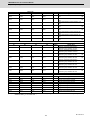
The CNC control and CNC status signals are arbitrarily assigned to the device and axis numbers by the parameter
"#1603 PLCdev_no" for each axis.
17
IB-1501272-B
M800/M80 Series PLC Interface Manual
2 Input/Output Signals with Controller
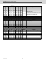
Device No.
$1
$2
$3
$4
Abbrev.
Signal name
XA60
XA68
XA70
XA78
Vertical axis pull-up prevented 1st axis
XA61
XA69
XA71
XA79
Vertical axis pull-up prevented 2nd axis
XA62
XA6A
XA72
XA7A
Vertical axis pull-up prevented 3rd axis
XA63
XA6B
XA73
XA7B
Vertical axis pull-up prevented 4th axis
XA64
XA6C
XA74
XA7C
Vertical axis pull-up prevented 5th axis
XA65
XA6D
XA75
XA7D
Vertical axis pull-up prevented 6th axis
XA66
XA6E
XA76
XA7E
Vertical axis pull-up prevented 7th axis
XA67
XA6F
XA77
XA7F
Vertical axis pull-up prevented 8th axis
Device No.
$1
$2
$3
$4
Abbrev.
Signal name
XA80
XA88
XA90
XA98
Mirror image status 1st axis
▲
XA81
XA89
XA91
XA99
Mirror image status 2nd axis
▲
XA82
XA8A
XA92
XA9A
Mirror image status 3rd axis
▲
XA83
XA8B
XA93
XA9B
Mirror image status 4th axis
▲
XA84
XA8C
XA94
XA9C
Mirror image status 5th axis
▲
XA85
XA8D
XA95
XA9D
Mirror image status 6th axis
▲
XA86
XA8E
XA96
XA9E
Mirror image status 7th axis
▲
XA87
XA8F
XA97
XA9F
Mirror image status 8th axis
▲
Device No.
$1
$2
$3
$4
Abbrev.
Signal name
XB00
XB08
XB10
XB18
Clamp command 1st axis
▲
XB01
XB09
XB11
XB19
Clamp command 2nd axis
▲
XB02
XB0A
XB12
XB1A
Clamp command 3rd axis
▲
XB03
XB0B
XB13
XB1B
Clamp command 4th axis
▲
XB04
XB0C
XB14
XB1C
Clamp command 5th axis
▲
XB05
XB0D
XB15
XB1D
Clamp command 6th axis
▲
XB06
XB0E
XB16
XB1E
Clamp command 7th axis
▲
XB07
XB0F
XB17
XB1F
Clamp command 8th axis
▲
Device No.
$1
$2
$3
$4
Abbrev.
Signal name
XB40
XB48
XB50
XB58
ROTSPM1 Spindle-mode rotary axis control mode 1st axis
XB41
XB49
XB51
XB59
ROTSPM2 Spindle-mode rotary axis control mode 2nd axis
XB42
XB4A
XB52
XB5A
ROTSPM3 Spindle-mode rotary axis control mode 3rd axis
XB43
XB4B
XB53
XB5B
ROTSPM4 Spindle-mode rotary axis control mode 4th axis
XB44
XB4C
XB54
XB5C
ROTSPM5 Spindle-mode rotary axis control mode 5th axis
XB45
XB4D
XB55
XB5D
ROTSPM6 Spindle-mode rotary axis control mode 6th axis
XB46
XB4E
XB56
XB5E
ROTSPM7 Spindle-mode rotary axis control mode 7th axis
XB4F
XB57
XB5F
ROTSPM8 Spindle-mode rotary axis control mode 8th axis
XB47
(Note)
The CNC control and CNC status signals are arbitrarily assigned to the device and axis numbers by the parameter
"#1603 PLCdev_no" for each axis.
IB-1501272-B
18
M800/M80 Series PLC Interface Manual
2 Input/Output Signals with Controller
Device No.
$1
$2
$3
$4
Abbrev.
Signal name
XB80
XB88
XB90
XB98
VGHLD1
Real-time tuning 1:
Speed gain hold-down ON 1st axis
XB81
XB89
XB91
XB99
VGHLD2
Real-time tuning 1:
Speed gain hold-down ON 2nd axis
XB82
XB8A
XB92
XB9A
VGHLD3
Real-time tuning 1:
Speed gain hold-down ON 3rd axis
XB83
XB8B
XB93
XB9B
VGHLD4
Real-time tuning 1:
Speed gain hold-down ON 4th axis
XB84
XB8C
XB94
XB9C
VGHLD5
Real-time tuning 1:
Speed gain hold-down ON 5th axis
XB85
XB8D
XB95
XB9D
VGHLD6
Real-time tuning 1:
Speed gain hold-down ON 6th axis
XB86
XB8E
XB96
XB9E
VGHLD7
Real-time tuning 1:
Speed gain hold-down ON 7th axis
XB87
XB8F
XB97
XB9F
VGHLD8
Real-time tuning 1:
Speed gain hold-down ON 8th axis
Device No.
$1
$2
$3
XBA0
XBA8
XBB0
XBB8
XBA1
XBA9
XBB1
XBB9
XBA2
XBAA
XBB2
XBBA
XBA3
XBAB
XBB3
XBBB
XBA4
XBAC
XBB4
XBBC
XBA5
XBAD
XBB5
XBBD
XBA6
XBAE
XBB6
XBBE
XBA7
XBAF
XBB7
XBBF
$4
Abbrev.
Signal name
$4
Abbrev.
Signal name
Device No.
$1
$2
$3
XBC0
XBC8
XBD0
XBD8
XBC1
XBC9
XBD1
XBD9
XBC2
XBCA
XBD2
XBDA
XBC3
XBCB
XBD3
XBDB
XBC4
XBCC
XBD4
XBDC
XBC5
XBCD
XBD5
XBDD
XBC6
XBCE
XBD6
XBDE
XBC7
XBCF
XBD7
XBDF
(Note)
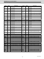
The CNC control and CNC status signals are arbitrarily assigned to the device and axis numbers by the parameter
"#1603 PLCdev_no" for each axis.
19
IB-1501272-B
M800/M80 Series PLC Interface Manual
2 Input/Output Signals with Controller
Device No.
$1
$2
$3
$4
Abbrev.
Signal name
XBE0
XBE8
XBF0
XBF8
Machine group-based alarm stop:
GQEMGO
Machine group-based PLC interlock ON 1st
1
axis
XBE1
XBE9
XBF1
XBF9
GQEMGO
Machine group-based PLC interlock ON 2nd
2
Machine group-based alarm stop:
axis
Machine group-based alarm stop:
XBE2
XBEA
XBF2
GQEMGO
Machine group-based PLC interlock ON 3rd
3
XBFA
axis
Machine group-based alarm stop:
XBE3
XBEB
XBF3
GQEMGO
Machine group-based PLC interlock ON 4th
4
XBFB
axis
Machine group-based alarm stop:
XBE4
XBEC
XBF4
GQEMGO
Machine group-based PLC interlock ON 5th
5
XBFC
axis
Machine group-based alarm stop:
XBE5
XBED
XBF5
GQEMGO
Machine group-based PLC interlock ON 6th
6
XBFD
axis
Machine group-based alarm stop:
XBE6
XBEE
XBF6
GQEMGO
Machine group-based PLC interlock ON 7th
7
XBFE
axis
Machine group-based alarm stop:
XBE7
XBEF
XBF7
GQEMGO
Machine group-based PLC interlock ON 8th
8
XBFF
axis
(Note)
The CNC control and CNC status signals are arbitrarily assigned to the device and axis numbers by the parameter
"#1603 PLCdev_no" for each axis.
IB-1501272-B
20
M800/M80 Series PLC Interface Manual
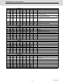
2 Input/Output Signals with Controller
Device No.
$1
$2
$3
$4
XC00
XD40
XE80
XFC0
X1100
$5
X1240
$6
X1380
$7
X14C0 JO
$8
Abbrev.
In jog mode
Signal name
XC01
XD41
XE81
XFC1
X1101
X1241
X1381
X14C1 HO
In handle mode
XC02
XD42
XE82
XFC2
X1102
X1242
X1382
X14C2 SO
In incremental mode
XC03
XD43
XE83
XFC3
X1103
X1243
X1383
X14C3 PTPO
In manual arbitrary feed mode
XC04
XD44
XE84
XFC4
X1104
X1244
X1384
X14C4 ZRNO
In reference position return mode
XC05
XD45
XE85
XFC5
X1105
X1245
X1385
X14C5 ASTO
In automatic initial set mode
In JOG-handle simultaneous mode
XC06
XD46
XE86
XFC6
X1106
X1246
X1386
X14C6
XC07
XD47
XE87
XFC7
X1107
X1247
X1387
X14C7
$1
$2
$3
$4
XC08
XD48
XE88
XFC8
X1108
X1248
X1388
X14C8 MEMO
In memory mode
XC09
XD49
XE89
XFC9
X1109
X1249
X1389
X14C9 TO
In tape mode
XC0A
XD4A
XE8A
XFCA
X110A X124A X138A X14CA
In online operation mode
XC0B
XD4B
XE8B
XFCB
X110B X124B X138B X14CB DO
In MDI mode
XC0C
XD4C
XE8C
XFCC
X110C X124C X138C X14CC
XC0D
XD4D
XE8D
XFCD
X110D X124D X138D X14CD
XC0E
XD4E
XE8E
XFCE
X110E X124E X138E X14CE SBSMO
XC0F
XD4F
XE8F
XFCF
X110F X124F X138F X14CF
$1
$2
$3
$4
XC10
XD50
XE90
XFD0
X1110
X1250
X1390
X14D0 MA
Controller ready completion
XC11
XD51
XE91
XFD1
X1111
X1251
X1391
X14D1 SA
Servo ready completion
XC12
XD52
XE92
XFD2
X1112
X1252
X1392
X14D2 OP
In automatic operation "run"
XC13
XD53
XE93
XFD3
X1113
X1253
X1393
X14D3 STL
In automatic operation "start"
XC14
XD54
XE94
XFD4
X1114
X1254
X1394
X14D4 SPL
In automatic operation "pause"
XC15
XD55
XE95
XFD5
X1115
X1255
X1395
X14D5 RST
In "reset"
XC16
XD56
XE96
XFD6
X1116
X1256
X1396
X14D6 CXN
In manual arbitrary feed
XC17
XD57
XE97
XFD7
X1117
X1257
X1397
X14D7 RWD
In rewind
Device No.
$5
$6
$7
$8
Abbrev.
Signal name
Sub part system control: Sub part system control I mode
ON
Device No.
$5
$6
$7
$8
Abbrev.
21
Signal name
IB-1501272-B
M800/M80 Series PLC Interface Manual
2 Input/Output Signals with Controller
Device No.
$1
$2
$3
$4
XC18
XD58
XE98
XFD8
X1118
$5
X1258
$6
X1398
$7
X14D8 DEN
$8
Abbrev.
Motion command completion
Signal name
XC19
XD59
XE99
XFD9
X1119
X1259
X1399
X14D9 TIMP
All axes in-position
XC1A
XD5A
XE9A
XFDA
X111A X125A X139A X14DA TSMZ
XC1B
XD5B
XE9B
XFDB
X111B X125B X139B X14DB
XC1C
XD5C
XE9C
XFDC
X111C X125C X139C X14DC CXFIN
Manual arbitrary feed completion
XC1D
XD5D
XE9D
XFDD
X111D X125D X139D X14DD
External search finished
All axes smoothing zero
XC1E
XD5E
XE9E
XFDE
X111E X125E X139E X14DE
XC1F
XD5F
XE9F
XFDF
X111F X125F X139F X14DF
$1
$2
$3
$4
XC20
XD60
XEA0
XFE0
X1120
X1260
X13A0 X14E0 RPN
XC21
XD61
XEA1
XFE1
X1121
X1261
X13A1 X14E1 CUT
In cutting feed
XC22
XD62
XEA2
XFE2
X1122
X1262
X13A2 X14E2 TAP
In tapping
XC23
XD63
XEA3
XFE3
X1123
X1263
X13A3 X14E3 THRD
In thread cutting
XC24
XD64
XEA4
XFE4
X1124
X1264
X13A4 X14E4 SYN
In synchronous feed
XC25
XD65
XEA5
XFE5
X1125
X1265
X13A5 X14E5 CSS
In constant surface speed
XC26
XD66
XEA6
XFE6
X1126
X1266
X13A6 X14E6 SKIP
In skip
XC27
XD67
XEA7
XFE7
X1127
X1267
X13A7 X14E7 ZRNN
In reference position return
In high-speed machining mode (G05)
Device No.
IB-1501272-B
$5
$6
$7
$8
Abbrev.
22
Signal name
In rapid traverse
M800/M80 Series PLC Interface Manual
2 Input/Output Signals with Controller
Device No.
$1
$2
$3
$4
XC28
XD68
XEA8
XFE8
X1128
$5
X1268
$6
X13A8 X14E8 INCH
$7
$8
Abbrev.
In inch unit selection
Signal name
XC29
XD69
XEA9
XFE9
X1129
X1269
X13A9 X14E9 DLKN
In display lock
XC2A
XD6A
XEAA
XFEA
X112A X126A X13AA X14EA F1DN
F 1-digit commanded
XC2B
XD6B
XEAB
XFEB
X112B X126B X13AB X14EB TLFO
In tool life management
XC2C
XD6C
XEAC
XFEC
X112C X126C X13AC X14EC
Tool life management:
Temporary cancel of tool life expiration ON
XC2D
XD6D
XEAD
XFED
X112D X126D X13AD X14ED
Tool life management:
Temporary cancel of tool group life expiration ON
XC2E
XD6E
XEAE
XFEE
X112E X126E X13AE X14EE TLOV
Tool life over
XC2F
XD6F
XEAF
XFEF
X112F X126F X13AF X14EF
Tool group life over
$1
$2
$3
$4
XC30
XD70
XEB0
XFF0
X1130
X1270
X13B0 X14F0 F11
F1-digit No. code 1
XC31
XD71
XEB1
XFF1
X1131
X1271
X13B1 X14F1 F12
F1-digit No. code 2
XC32
XD72
XEB2
XFF2
X1132
X1272
X13B2 X14F2 F14
F1-digit No. code 4
XC33
XD73
XEB3
XFF3
X1133
X1273
X13B3 X14F3 F18
F1-digit No. code 8
XC34
XD74
XEB4
XFF4
X1134
X1274
X13B4 X14F4
Timing synchronization between part systems
XC35
XD75
XEB5
XFF5
X1135
X1275
X13B5 X14F5 PCINO
In PLC interrupt
XC36
XD76
XEB6
XFF6
X1136
X1276
X13B6 X14F6
XC37
XD77
XEB7
XFF7
X1137
X1277
X13B7 X14F7 ASLE
$1
$2
$3
$4
XC38
XD78
XEB8
XFF8
X1138
X1278
X13B8 X14F8
XC39
XD79
XEB9
XFF9
X1139
X1279
X13B9 X14F9
XC3A
XD7A
XEBA
XFFA
X113A X127A X13BA X14FA
XC3B
XD7B
XEBB
XFFB
X113B X127B X13BB X14FB
XC3C
XD7C
XEBC
XFFC
X113C X127C X13BC X14FC
XC3D
XD7D
XEBD
XFFD
X113D X127D X13BD X14FD
XC3E
XD7E
XEBE
XFFE
X113E X127E X13BE X14FE
XC3F
XD7F
XEBF
XFFF
X113F X127F X13BF X14FF
$1
$2
$3
XC40
XD80
XEC0
X1000
X1140
X1280
X13C0 X1500
DM00
M code independent output M00
XC41
XD81
XEC1
X1001
X1141
X1281
X13C1 X1501
DM01
M code independent output M01
XC42
XD82
XEC2
X1002
X1142
X1282
X13C2 X1502
DM02
M code independent output M02
XC43
XD83
XEC3
X1003
X1143
X1283
X13C3 X1503
DM30
M code independent output M30
XC44
XD84
XEC4
X1004
X1144
X1284
X13C4 X1504
XC45
XD85
XEC5
X1005
X1145
X1285
X13C5 X1505
XC46
XD86
XEC6
X1006
X1146
X1286
X13C6 X1506
XC47
XD87
XEC7
X1007
X1147
X1287
X13C7 X1507
Device No.
$5
$6
$7
$8
Abbrev.
Signal name
Illegal axis selected
Device No.
$5
$6
$7
$8
Abbrev.
Signal name
Device No.
$4
$5
$6
$7
$8
Abbrev.
23
Signal name
IB-1501272-B
M800/M80 Series PLC Interface Manual
2 Input/Output Signals with Controller
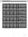
Device No.
$1
$2
$3
XC48
XD88
XEC8
X1008
$4
X1148
$5
X1288
$6
X13C8 X1508
$7
$8
Abbrev.
Signal name
XC49
XD89
XEC9
X1009
X1149
X1289
X13C9 X1509
XC4A
XD8A
XECA
X100A X114A X128A X13CA X150A
XC4B
XD8B
XECB
X100B X114B X128B X13CB X150B
XC4C
XD8C
XECC
X100C X114C X128C X13CC X150C
XC4D
XD8D
XECD
X100D X114D X128D X13CD X150D
XC4E
XD8E
XECE
X100E X114E X128E X13CE X150E SBS
Sub part system control: Sub part system processing
XC4F
XD8F
XECF
X100F X114F X128F X13CF X150F
In circular feed in manual mode
$1
$2
$3
XC50
XD90
XED0
X1010
X1150
X1290
X13D0 X1510
XC51
XD91
XED1
X1011
X1151
X1291
X13D1 X1511
XC52
XD92
XED2
X1012
X1152
X1292
X13D2 X1512
XC53
XD93
XED3
X1013
X1153
X1293
X13D3 X1513
XC54
XD94
XED4
X1014
X1154
X1294
X13D4 X1514
XC55
XD95
XED5
X1015
X1155
X1295
X13D5 X1515
XC56
XD96
XED6
X1016
X1156
X1296
X13D6 X1516
XC57
XD97
XED7
X1017
X1157
X1297
X13D7 X1517
$1
$2
$3
XC58
XD98
XED8
X1018
X1158
X1298
X13D8 X1518
XC59
XD99
XED9
X1019
X1159
X1299
X13D9 X1519
XC5A
XD9A
XEDA
X101A X115A X129A X13DA X151A
XC5B
XD9B
XEDB
X101B X115B X129B X13DB X151B
XC5C
XD9C
XEDC
X101C X115C X129C X13DC X151C
XC5D
XD9D
XEDD
X101D X115D X129D X13DD X151D
XC5E
XD9E
XEDE
X101E X115E X129E X13DE X151E
XC5F
XD9F
XEDF
X101F X115F X129F X13DF X151F
$1
$2
$3
XC60
XDA0
XEE0
X1020
X1160
X12A0 X13E0 X1520 MF1
M function strobe 1
XC61
XDA1
XEE1
X1021
X1161
X12A1 X13E1 X1521 MF2
M function strobe 2
XC62
XDA2
XEE2
X1022
X1162
X12A2 X13E2 X1522 MF3
M function strobe 3
XC63
XDA3
XEE3
X1023
X1163
X12A3 X13E3 X1523 MF4
M function strobe 4
XC64
XDA4
XEE4
X1024
X1164
X12A4 X13E4 X1524 SF1
S function strobe 1
XC65
XDA5
XEE5
X1025
X1165
X12A5 X13E5 X1525 SF2
S function strobe 2
XC66
XDA6
XEE6
X1026
X1166
X12A6 X13E6 X1526 SF3
S function strobe 3
XC67
XDA7
XEE7
X1027
X1167
X12A7 X13E7 X1527 SF4
S function strobe 4
In manual speed command valid
MMS
Manual numerical command
In tool escape and return mode
Device No.
$4
$5
$6
$7
$8
Abbrev.
TRTN2
Signal name
In tool retract and return 2 mode
Device No.
$4
$5
$6
$7
$8
Abbrev.
Signal name
Device No.
IB-1501272-B
$4
$5
$6
$7
$8
Abbrev.
24
Signal name
▲
M800/M80 Series PLC Interface Manual
2 Input/Output Signals with Controller
Device No.
$1
$2
$3
XC68
XDA8
XEE8
X1028
$4
X1168
$5
X12A8 X13E8 X1528
$6
$7
$8
TF1
Abbrev.
T function strobe 1
Signal name
XC69
XDA9
XEE9
X1029
X1169
X12A9 X13E9 X1529
TF2
T function strobe 2
XC6A
XDAA
XEEA
X102A X116A X12AA X13EA X152A TF3
T function strobe 3
XC6B
XDAB
XEEB
X102B X116B X12AB X13EB X152B TF4
T function strobe 4
XC6C
XDAC
XEEC
X102C X116C X12AC X13EC X152C BF1
2nd M function strobe 1
XC6D
XDAD
XEED
X102D X116D X12AD X13ED X152D BF2
2nd M function strobe 2
XC6E
XDAE
XEEE
X102E X116E X12AE X13EE X152E BF3
2nd M function strobe 3
XC6F
XDAF
XEEF
X102F X116F X12AF X13EF X152F BF4
2nd M function strobe 4
$1
$2
$3
XC70
XDB0
XEF0
X1030
X1170
X12B0 X13F0 X1530
SF5
S function strobe 5
XC71
XDB1
XEF1
X1031
X1171
X12B1 X13F1 X1531
SF6
S function strobe 6
XC72
XDB2
XEF2
X1032
X1172
X12B2 X13F2 X1532
SF7
S function strobe 7
XC73
XDB3
XEF3
X1033
X1173
X12B3 X13F3 X1533
SF8
S function strobe 8
XC74
XDB4
XEF4
X1034
X1174
X12B4 X13F4 X1534
XC75
XDB5
XEF5
X1035
X1175
X12B5 X13F5 X1535
XC76
XDB6
XEF6
X1036
X1176
X12B6 X13F6 X1536
XC77
XDB7
XEF7
X1037
X1177
X12B7 X13F7 X1537
$1
$2
$3
XC78
XDB8
XEF8
X1038
X1178
X12B8 X13F8 X1538
XC79
XDB9
XEF9
X1039
X1179
X12B9 X13F9 X1539
XC7A
XDBA
XEFA
X103A X117A X12BA X13FA X153A
XC7B
XDBB
XEFB
X103B X117B X12BB X13FB X153B
XC7C
XDBC
XEFC
X103C X117C X12BC X13FC X153C
XC7D
XDBD
XEFD
X103D X117D X12BD X13FD X153D
XC7E
XDBE
XEFE
X103E X117E X12BE X13FE X153E
XC7F
XDBF
XEFF
X103F X117F X12BF X13FF X153F CHPRCC
$1
$2
$3
XC80
XDC0
XF00
Device No.
$4
$5
$6
$7
$8
Abbrev.
Signal name
Device No.
$4
$5
$6
$7
$8
Abbrev.
Signal name
Chopping compensation update prevented
Device No.
$4
X1040
$5
X1180
$6
$7
X12C0 X1400
$8
Abbrev.
X1540
CHOP
Signal name
In chopping start
XC81
XDC1
XF01
X1041
X1181
X12C1 X1401
X1541
CHP1
Basic position -> upper dead point path flag
XC82
XDC2
XF02
X1042
X1182
X12C2 X1402
X1542
CHP2
Upper dead point -> bottom dead point path flag
XC83
XDC3
XF03
X1043
X1183
X12C3 X1403
X1543
CHP3
Bottom dead point -> upper dead point path flag
XC84
XDC4
XF04
X1044
X1184
X12C4 X1404
X1544
CHP4
Upper dead point -> basic position path flag
XC85
XDC5
XF05
X1045
X1185
X12C5 X1405
X1545
CHPMD
In chopping mode
XC86
XDC6
XF06
X1046
X1186
X12C6 X1406
X1546
Stroke compensation completion
XC87
XDC7
XF07
X1047
X1187
X12C7 X1407
X1547
Tool escape and return transit point recognition
completed
25
IB-1501272-B
M800/M80 Series PLC Interface Manual
2 Input/Output Signals with Controller
Device No.
$1
$2
$3
XC88
XDC8
XF08
X1048
$4
X1188
$5
X12C8 X1408
$6
$7
X1548
$8
Abbrev.
XC89
XDC9
XF09
X1049
X1189
X12C9 X1409
X1549
Signal name
XC8A
XDCA
XF0A
X104A X118A X12CA X140A X154A SSE
Search & start Error
XC8B
XDCB
XF0B
X104B X118B X12CB X140B X154B SSG
Search & start Search
XC8C
XDCC
XF0C
X104C X118C X12CC X140C X154C
XC8D
XDCD
XF0D
X104D X118D X12CD X140D X154D
XC8E
XDCE
XF0E
X104E X118E X12CE X140E X154E
XC8F
XDCF
XF0F
X104F X118F X12CF X140F X154F
Device No.
$1
$2
$3
XC90
XDD0
XF10
X1050
$4
X1190
$5
X12D0 X1410
$6
$7
X1550
$8
Abbrev.
Signal name
XC91
XDD1
XF11
X1051
X1191
X12D1 X1411
X1551
XC92
XDD2
XF12
X1052
X1192
X12D2 X1412
X1552
XC93
XDD3
XF13
X1053
X1193
X12D3 X1413
X1553
TCP
Tool change position return completion
XC94
XDD4
XF14
X1054
X1194
X12D4 X1414
X1554
TCRQ
New tool change
XC95
XDD5
XF15
X1055
X1195
X12D5 X1415
X1555
All spindles simultaneous control (G47.1)
XC96
XDD6
XF16
X1056
X1196
X12D6 X1416
X1556
Life prediction
XC97
XDD7
XF17
X1057
X1197
X12D7 X1417
X1557
$1
$2
$3
XC98
XDD8
XF18
X1058
X1198
X12D8 X1418
X1558
AL1
XC99
XDD9
XF19
X1059
X1199
X12D9 X1419
X1559
AL2
XC9A
XDDA
XF1A
X105A X119A X12DA X141A X155A AL3
NC alarm 3 (Program error)
XC9B
XDDB
XF1B
X105B X119B X12DB X141B X155B AL4
NC alarm 4 (Operation error)
XC9C
XDDC
XF1C
X105C X119C X12DC X141C X155C WR1
NC warning (Servo warning)
XC9D
XDDD
XF1D
X105D X119D X12DD X141D X155D
XC9E
XDDE
XF1E
X105E X119E X12DE X141E X155E
XC9F
XDDF
XF1F
X105F X119F X12DF X141F X155F
Device No.
$4
$5
$6
$7
$8
Abbrev.
Signal name
NC alarm 1
NC alarm 2 (Servo alarm)
Device No.
$1
XCA0
$2
XDE0
$3
XF20
$4
X1060
$5
$6
$7
X11A0 X12E0 X1420
$8
Abbrev.
X1560
Signal name
Load monitor I :Teaching/Monitor mode in
execution
▲
▲
XCA1
XDE1
XF21
X1061
X11A1 X12E1 X1421
X1561
Load monitor I : Teaching mode valid
XCA2
XDE2
XF22
X1062
X11A2 X12E2 X1422
X1562
Load monitor I : Monitor mode valid
▲
XCA3
XDE3
XF23
X1063
X11A3 X12E3 X1423
X1563
Load monitor I : Adaptive control in execution
▲
XCA4
XDE4
XF24
X1064
X11A4 X12E4 X1424
X1564
XCA5
XDE5
XF25
X1065
X11A5 X12E5 X1425
X1565
TRVE
Tap retract possible
XCA6
XDE6
XF26
X1066
X11A6 X12E6 X1426
X1566
PCNT
No. of work machining over
XCA7
XDE7
XF27
X1067
X11A7 X12E7 X1427
X1567
ABSW
Absolute position warning
IB-1501272-B
26
M800/M80 Series PLC Interface Manual
2 Input/Output Signals with Controller
Device No.
$1
$2
$3
XCA8
XDE8
XF28
X1068
$4
X11A8 X12E8 X1428
$5
$6
$7
X1568
$8
Abbrev.
Signal name
XCA9
XDE9
XF29
X1069
X11A9 X12E9 X1429
X1569
XCAA
XDEA
XF2A
X106A X11AA X12EA X142A X156A
Optimum acceleration/deceleration parameter
switch completion [axis]
XCAB
XDEB
XF2B
X106B X11AB X12EB X142B X156B ESTSVIN
Optimum acceleration/deceleration selection : NC
▲
axis inertia estimation in progress
XCAC
XDEC
XF2C
Optimum acceleration/deceleration selection : NC
X106C X11AC X12EC X142C X156C GETSVAF axis estimated resonance frequency acquisition in ▲
progress
XCAD
XDED
XF2D
X106D X11AD X12ED X142D X156D
XCAE
XDEE
XF2E
X106E X11AE X12EE X142E X156E HOBRTM Hob machining: retracting
XCAF
XDEF
XF2F
X106F X11AF X12EF X142F X156F HOBRTF
$1
$2
$3
XCB0
XDF0
XF30
X1070
X11B0 X12F0 X1430
XCB1
XDF1
XF31
X1071
X11B1 X12F1 X1431
X1571
XCB2
XDF2
XF32
X1072
X11B2 X12F2 X1432
X1572
In spindle-spindle polygon mode
Spindle-spindle polygon synchronization completion
In axis name switch
▲
Hob machining: retract complete
Device No.
$4
$5
$6
$7
$8
Abbrev.
X1570
XCB3
XDF3
XF33
X1073
X11B3 X12F3 X1433
X1573
XCB4
XDF4
XF34
X1074
X11B4 X12F4 X1434
X1574
XCB5
XDF5
XF35
X1075
X11B5 X12F5 X1435
X1575
XCB6
XDF6
XF36
X1076
X11B6 X12F6 X1436
X1576
XCB7
XDF7
XF37
X1077
X11B7 X12F7 X1437
X1577
$1
$2
$3
XCB8
XDF8
XF38
X1078
X11B8 X12F8 X1438
X1578
XCB9
XDF9
XF39
X1079
X11B9 X12F9 X1439
X1579
XCBA
XDFA
XF3A
X107A X11BA X12FA X143A X157A
XCBB
XDFB
XF3B
X107B X11BB X12FB X143B X157B
XCBC
XDFC
XF3C
X107C X11BC X12FC X143C X157C
XCBD
XDFD
XF3D
X107D X11BD X12FD X143D X157D
XCBE
XDFE
XF3E
X107E X11BE X12FE X143E X157E
XCBF
XDFF
XF3F
X107F X11BF X12FF X143F X157F
$2
$3
Signal name
In spindle-NC axis polygon mode
AL5
NC alarm 5
Device No.
$4
$5
$6
$7
$8
Abbrev.
Signal name
In 3-dimensional coordinate conversion
Device No.
$1
XCC0
XE00
XF40
$4
X1080
$5
$6
X11C0 X1300
$7
X1440
$8
Abbrev.
X1580
RTAP
Signal name
In synchronized tapping selection
(M command)
XCC1
XE01
XF41
X1081
X11C1 X1301
X1441
X1581
In small diameter deep hole cycle
XCC2
XE02
XF42
X1082
X11C2 X1300
X1442
X1582
High-speed retract function valid state
▲
XCC3
XE03
XF43
X1083
X11C3 X1303
X1443
X1583
In high-speed retract function operation
▲
XCC4
XE04
XF44
X1084
X11C4 X1304
X1444
X1584
XCC5
XE05
XF45
X1085
X11C5 X1305
X1445
X1585
XCC6
XE06
XF46
X1086
X11C6 X1306
X1446
X1586
XCC7
XE07
XF47
X1087
X11C7 X1307
X1447
X1587
27
IB-1501272-B
M800/M80 Series PLC Interface Manual
2 Input/Output Signals with Controller
Device No.
$1
$2
$3
XCC8
XE08
XF48
X1088
$4
X11C8 X1308
$5
$6
X1448
$7
X1588
$8
Abbrev.
In barrier valid (left)
Signal name
XCC9
XE09
XF49
X1089
X11C9 X1309
X1449
X1589
In barrier valid (right)
XCCA
XE0A
XF4A
X108A X11CA X130A X144A X158A TLMSFIN
XCCB
XE0B
XF4B
X108B X11CB X130B X144B X158B TLMSERR Tool length measurement error
Tool length measurement completion
XCCC
XE0C
XF4C
X108C X11CC X130C X144C X158C
XCCD
XE0D
XF4D
X108D X11CD X130D X144D X158D
XCCE
XE0E
XF4E
X108E X11CE X130E X144E X158E TLMSSELO Tool length measurement sub-side selected
▲
XCCF
XE0F
XF4F
X108F X11CF X130F X144F X158F
▲
$2
$3
XCD0
XE10
XF50
X1090
X11D0 X1310
X1450
X1590
TRME
With tool retract amount command
▲
XCD1
XE11
XF51
X1091
X11D1 X1311
X1451
X1591
TRRP
In tool repositioning
▲
XCD2
XE12
XF52
X1092
X11D2 X1312
X1452
X1592
XCD3
XE13
XF53
X1093
X11D3 X1313
X1453
X1593
XCD4
XE14
XF54
X1094
X11D4 X1314
X1454
X1594
XCD5
XE15
XF55
X1095
X11D5 X1315
X1455
X1595
XCD6
XE16
XF56
X1096
X11D6 X1316
X1456
X1596
XCD7
XE17
XF57
X1097
X11D7 X1317
X1457
X1597
$2
$3
XCD8
XE18
XF58
X1098
X11D8 X1318
X1458
X1598
XCD9
XE19
XF59
X1099
X11D9 X1319
X1459
X1599
XCDA
XE1A
XF5A
X109A X11DA X131A X145A X159A
XCDB
XE1B
XF5B
X109B X11DB X131B X145B X159B
XCDC
XE1C
XF5C
X109C X11DC X131C X145C X159C
XCDD
XE1D
XF5D
X109D X11DD X131D X145D X159D
XCDE
XE1E
XF5E
X109E X11DE X131E X145E X159E
XCDF
XE1F
XF5F
X109F X11DF X131F X145F X159F
$1
$2
$3
XCE0
XE20
XF60
X10A0 X11E0 X1320
X1460 X15A0
XCE1
XE21
XF61
X10A1 X11E1 X1321
X1461 X15A1
XCE2
XE22
XF62
X10A2 X11E2 X1322
X1462 X15A2
XCE3
XE23
XF63
X10A3 X11E3 X1323
X1463 X15A3
XCE4
XE24
XF64
X10A4 X11E4 X1324
X1464 X15A4
XCE5
XE25
XF65
X10A5 X11E5 X1325
X1465 X15A5
XCE6
XE26
XF66
X10A6 X11E6 X1326
X1466 X15A6
XCE7
XE27
XF67
X10A7 X11E7 X1327
X1467 X15A7
Tool retract position reached
▲
▲
Device No.
$1
$4
$5
$6
$7
$8
Abbrev.
Signal name
Device No.
$1
$4
$5
$6
$7
$8
Abbrev.
Signal name
Door open enable
Device No.
IB-1501272-B
$4
$5
$6
$7
$8
Abbrev.
28
Signal name
M800/M80 Series PLC Interface Manual
2 Input/Output Signals with Controller
Device No.
$1
$2
$3
$4
$5
$6
$7
$8
Abbrev.
XCE8
XE28
XF68
X10A8 X11E8 X1328
X1468 X15A8
XCE9
XE29
XF69
X10A9 X11E9 X1329
X1469 X15A9
XCEA
XE2A
XF6A
X10AA X11EA X132A X146A X15AA
XCEB
XE2B
XF6B
X10AB X11EB X132B X146B X15AB
Signal name
Door open enable
(2 channels per 1 part system)
XCEC
XE2C
XF6C
X10AC X11EC X132C X146C X15AC
XCED
XE2D
XF6D
X10AD X11ED X132D X146D X15AD
Optimum machining diagnosis in progress
▲
XCEE
XE2E
XF6E
X10AE X11EE X132E X146E X15AE
Load monitor I : Cutting torque estimation in
progress
XCEF
XE2F
XF6F
X10AF X11EF X132F X146F X15AF
Load monitor I : Cutting torque estimation
completed
$1
$2
$3
XCF0
XE30
XF70
X10B0 X11F0 X1330
X1470
X15B0
XCF1
XE31
XF71
X10B1 X11F1 X1331
X1471
X15B1
XCF2
XE32
XF72
X10B2 X11F2 X1332
X1472
X15B2
XCF3
XE33
XF73
X10B3 X11F3 X1333
X1473
X15B3
XCF4
XE34
XF74
X10B4 X11F4 X1334
X1474
X15B4
XCF5
XE35
XF75
X10B5 X11F5 X1335
X1475
X15B5
XCF6
XE36
XF76
X10B6 X11F6 X1336
X1476
X15B6
XCF7
XE37
XF77
X10B7 X11F7 X1337
X1477
X15B7
$1
$2
$3
XCF8
XE38
XF78
X10B8 X11F8 X1338
X1478
X15B8
XCF9
XE39
XF79
X10B9 X11F9 X1339
X1479
X15B9 GLMT
XCFA
XE3A
XF7A
X10BA X11FA X133A X147A X15BA
XCFB
XE3B
XF7B
X10BB X11FB X133B X147B X15BB
XCFC
XE3C
XF7C
X10BC X11FC X133C X147C X15BC
XCFD
XE3D
XF7D
X10BD X11FD X133D X147D X15BD
XCFE
XE3E
XF7E
X10BE X11FE X133E X147E X15BE
XCFF
XE3F
XF7F
X10BF X11FF X133F X147F X15BF
$1
$2
$3
XD00
XE40
XF80
X10C0 X1200
X1340
X1480
X15C0
XD01
XE41
XF81
X10C1 X1201
X1341
X1481
X15C1
XD02
XE42
XF82
X10C2 X1202
X1342
X1482
X15C2
XD03
XE43
XF83
X10C3 X1203
X1343
X1483
X15C3
XD04
XE44
XF84
X10C4 X1204
X1344
X1484
X15C4
XD05
XE45
XF85
X10C5 X1205
X1345
X1485
X15C5
XD06
XE46
XF86
X10C6 X1206
X1346
X1486
X15C6
XD07
XE47
XF87
X10C7 X1207
X1347
X1487
X15C7
Device No.
$4
$5
$6
$7
$8
Abbrev.
Signal name
Abbrev.
Signal name
Device No.
$4
$5
$6
$7
$8
Torque limitation skip: G160 torque limit ON
Device No.
$4
$5
$6
$7
$8
Abbrev.
29
Signal name
IB-1501272-B
M800/M80 Series PLC Interface Manual
2 Input/Output Signals with Controller
Device No.
$1
$2
$3
XD08
XE48
XF88
X10C8 X1208
$4
$5
X1348
$6
X1488
$7
X15C8
$8
Abbrev.
XD09
XE49
XF89
X10C9 X1209
X1349
X1489
X15C9
XD0A
XE4A
XF8A
X10CA X120A X134A X148A X15CA
XD0B
XE4B
XF8B
X10CB X120B X134B X148B X15CB G0AC
XD0C
XE4C
XF8C
X10CC X120C X134C X148C X15CC
XD0D
XE4D
XF8D
X10CD X120D X134D X148D X15CD
Signal name
Rapid traverse time constant: In switchover
XD0E
XE4E
XF8E
X10CE X120E X134E X148E X15CE
XD0F
XE4F
XF8F
X10CF X120F X134F X148F X15CF
$1
$2
$3
XD10
XE50
XF90
X10D0 X1210
X1350
X1490
X15D0
XD11
XE51
XF91
X10D1 X1211
X1351
X1491
X15D1
XD12
XE52
XF92
X10D2 X1212
X1352
X1492
X15D2
XD13
XE53
XF93
X10D3 X1213
X1353
X1493
X15D3
XD14
XE54
XF94
X10D4 X1214
X1354
X1494
X15D4
XD15
XE55
XF95
X10D5 X1215
X1355
X1495
X15D5
XD16
XE56
XF96
X10D6 X1216
X1356
X1496
X15D6
XD17
XE57
XF97
X10D7 X1217
X1357
X1497
X15D7
$1
$2
$3
XD18
XE58
XF98
X10D8 X1218
X1358
X1498
X15D8 MJST
Tool axis coordinate system in 3D manual feed (JOG,
INC)
XD19
XE59
XF99
X10D9 X1219
X1359
X1499
X15D9 MJSB
Table coordinate system in 3D manual feed (JOG, INC)
XD1A
XE5A
XF9A
X10DA X121A X135A X149A X15DA MJSF
Feature coordinate system in 3D manual feed (JOG,
INC)
XD1B
XE5B
XF9B
X10DB X121B X135B X149B X15DB MH1ST
Tool axis coordinate system in 3D manual feed (1st
handle)
XD1C
XE5C
XF9C
X10DC X121C X135C X149C X15DC MH1SB
Table coordinate system in 3D manual feed (1st handle)
XD1D
XE5D
XF9D
X10DD X121D X135D X149D X15DD MH1SF
Feature coordinate system in 3D manual feed (1st
handle)
XD1E
XE5E
XF9E
X10DE X121E X135E X149E X15DE MH2ST
Tool axis coordinate system in 3D manual feed (2nd
handle)
XD1F
XE5F
XF9F
X10DF X121F X135F X149F X15DF MH2SB
Table coordinate system in 3D manual feed (2nd handle)
$1
$2
$3
Device No.
$4
$5
$6
$7
$8
Abbrev.
Signal name
3D coordinate conversion : Manual feed valid
▲
Device No.
$4
$5
$6
$7
$8
Abbrev.
Signal name
Device No.
$4
$5
$6
$7
$8
Abbrev.
Signal name
XD20
XE60
XFA0
X10E0 X1220
X1360
X14A0 X15E0 MH2SF
Feature coordinate system in 3D manual feed (2nd
handle)
XD21
XE61
XFA1
X10E1 X1221
X1361
X14A1 X15E1 MH3ST
Tool axis coordinate system in 3D manual feed (3rd
handle)
XD22
XE62
XFA2
X10E2 X1222
X1362
X14A2 X15E2 MH3SB
Table coordinate system in 3D manual feed (3rd handle)
XD23
XE63
XFA3
X10E3 X1223
X1363
X14A3 X15E3 MH3SF
Feature coordinate system in 3D manual feed (3rd
handle)
XD24
XE64
XFA4
X10E4 X1224
X1364
X14A4 X15E4
XD25
XE65
XFA5
X10E5 X1225
X1365
X14A5 X15E5
XD26
XE66
XFA6
X10E6 X1226
X1366
X14A6 X15E6
XD27
XE67
XFA7
X10E7 X1227
X1367
X14A7 X15E7 TCPRS
IB-1501272-B
30
In tool center point rotation
M800/M80 Series PLC Interface Manual
2 Input/Output Signals with Controller
Device No.
$1
$2
$3
XD28
XE68
XFA8
X10E8 X1228
X1368
X14A8 X15E8 RSSCT
R-Navi: selecting machine surface
XD29
XE69
XFA9
X10E9 X1229 X1369
X14A9 X15E9 RSIND
R-Navi: machine surface indexing
XD2A
XE6A
XFAA
X10EA X122A X136A X14AA X15EA RSIDF
XD2B
XE6B
XFAB
X10EB X122B X136B X14AB X15EB
XD2C
XE6C
XFAC
X10EC X122C X136C X14AC X15EC
XD2D
XE6D
XFAD
X10ED X122D X136D X14AD X15ED
XD2E
XE6E
XFAE
X10EE X122E X136E X14AE X15EE
XD2F
XE6F
XFAF
X10EF X122F X136F X14AF X15EF
Device
Abbrev.
$4
$5
$6
$7
$8
Abbrev.
Signal name
Device
X1870
X1878
X1871
X1879
X1872
X187A
X1873
X187B
X1874
X187C
X1875
X187D
X1876
X187E
X1877
X187F
31
Signal name
R-Navi: machine surface index complete
Abbrev.
Signal name
Edit/search window displayed
IB-1501272-B
M800/M80 Series PLC Interface Manual
2 Input/Output Signals with Controller
Device No.
1stSP
2ndSP
3rdSP
4thSP
5thSP
6thSP
7thSP
8thSP
Abbrev
Signal name
X1880
X18E0
X1940
X19A0
X1A00
X1A60
X1AC0
X1B20
SUPP
Spindle rotation upper limit exceeded
X1881
X18E1
X1941
X19A1
X1A01
X1A61
X1AC1
X1B21
SLOW
Spindle rotation lower limit exceeded
X1882
X18E2
X1942
X19A2
X1A02
X1A62
X1AC2
X1B22
SIGE
S command gear No. illegal
X1883
X18E3
X1943
X19A3
X1A03
X1A63
X1AC3
X1B23
SOVE
S command max./min. command value over
X1884
X18E4
X1944
X19A4
X1A04
X1A64
X1AC4
X1B24
SNGE
S command no gear selected
X1885
X18E5
X1945
X19A5
X1A05
X1A65
X1AC5
X1B25
GR1
Spindle gear shift command 1
X1886
X18E6
X1946
X19A6
X1A06
X1A66
X1AC6
X1B26
GR2
Spindle gear shift command 2
X1887
X18E7
X1947
X19A7
X1A07
X1A67
X1AC7
X1B27
-
(Always "0")
Device No.
1stSP
2ndSP
3rdSP
4thSP
5thSP
6thSP
7thSP
8thSP
Abbrev
Signal name
X1888
X18E8
X1948
X19A8
X1A08
X1A68
X1AC8
X1B28
Spindle 2nd in-position
X1889
X18E9
X1949
X19A9
X1A09
X1A69
X1AC9
X1B29
CDO
X188A
X18EA
X194A
X19AA
X1A0A
X1A6A
X1ACA
X1B2A
VRO
Speed detection
X188B
X18EB
X194B
X19AB
X1A0B
X1A6B
X1ACB
X1B2B
FLO
In spindle alarm
X188C
X18EC
X194C
X19AC
X1A0C
X1A6C
X1ACC
X1B2C
ZSO
Zero speed
X188D
X18ED
X194D
X19AD
X1A0D
X1A6D
X1ACD
X1B2D
USO
Spindle up-to-speed
X188E
X18EE
X194E
X19AE
X1A0E
X1A6E
X1ACE
X1B2E
ORAO
Spindle in-position
X188F
X18EF
X194F
X19AF
X1A0F
X1A6F
X1ACF
X1B2F
LCSA
In L coil selection
Current detection
Device No.
1stSP
2ndSP
3rdSP
4thSP
5thSP
6thSP
7thSP
8thSP
Abbrev
Signal name
X1890
X18F0
X1950
X19B0
X1A10
X1A70
X1AD0
X1B30
SMA
X1891
X18F1
X1951
X19B1
X1A11
X1A71
X1AD1
X1B31
SSA
Spindle ready-ON
Spindle servo-ON
X1892
X18F2
X1952
X19B2
X1A12
X1A72
X1AD2
X1B32
SEMG
In spindle emergency stop
X1893
X18F3
X1953
X19B3
X1A13
X1A73
X1AD3
X1B33
SSRN
In spindle forward run
X1894
X18F4
X1954
X19B4
X1A14
X1A74
X1AD4
X1B34
SSRI
X1895
X18F5
X1955
X19B5
X1A15
X1A75
X1AD5
X1B35
In spindle reverse run
Z phase passed
X1896
X18F6
X1956
X19B6
X1A16
X1A76
X1AD6
X1B36
SIMP
Position loop in-position
X1897
X18F7
X1957
X19B7
X1A17
X1A77
X1AD7
X1B37
STLQ
In spindle torque limit
Device No.
1stSP
2ndSP
3rdSP
4thSP
5thSP
6thSP
7thSP
8thSP
Abbrev
Signal name
X1898
X18F8
X1958
X19B8
X1A18
X1A78
X1AD8
X1B38
X1899
X18F9
X1959
X19B9
X1A19
X1A79
X1AD9
X1B39
X189A
X18FA
X195A
X19BA
X1A1A
X1A7A
X1ADA
X1B3A
X189B
X18FB
X195B
X19BB
X1A1B
X1A7B
X1ADB
X1B3B
X189C
X18FC
X195C
X19BC
X1A1C
X1A7C
X1ADC
X1B3C
X189D
X18FD
X195D
X19BD
X1A1D
X1A7D
X1ADD
X1B3D
SD2
Speed detection 2
X189E
X18FE
X195E
X19BE
X1A1E
X1A7E
X1ADE
X1B3E
MCSA
In M coil selection
X189F
X18FF
X195F
X19BF
X1A1F
X1A7F
X1ADF
X1B3F
IB-1501272-B
32
Spindle torque limit reached
Index positioning completion
M800/M80 Series PLC Interface Manual
2 Input/Output Signals with Controller
Device No.
1stSP
2ndSP
3rdSP
4thSP
5thSP
6thSP
7thSP
8thSP
Abbrev
Signal name
X18A0
X1900
X1960
X19C0
X1A20
X1A80
X1AE0
X1B40
ENB
Spindle enable
X18A1
X1901
X1961
X19C1
X1A21
X1A81
X1AE1
X1B41
LRUC
In changeover to L coil
▲
X18A2
X1902
X1962
X19C2
X1A22
X1A82
X1AE2
X1B42
HRUC
In changeover to H coil
▲
X18A3
X1903
X1963
X19C3
X1A23
X1A83
X1AE3
X1B43
X18A4
X1904
X1964
X19C4
X1A24
X1A84
X1AE4
X1B44
X18A5
X1905
X1965
X19C5
X1A25
X1A85
X1AE5
X1B45
X18A6
X1906
X1966
X19C6
X1A26
X1A86
X1AE6
X1B46
X18A7
X1907
X1967
X19C7
X1A27
X1A87
X1AE7
X1B47
Spindle synchronization speed detect
▲
Device No.
1stSP
2ndSP
3rdSP
4thSP
5thSP
6thSP
7thSP
8thSP
Abbrev
Signal name
X18A8
X1908
X1968
X19C8
X1A28
X1A88
X1AE8
X1B48
SPSYN
In spindle synchronization
1
X18A9
X1909
X1969
X19C9
X1A29
X1A89
X1AE9
X1B49
FSPRV
X18AA
X190A
X196A
X19CA
X1A2A
X1A8A
X1AEA
X1B4A
FSPPH Spindle phase synchronization completion
X18AB
X190B
X196B
X19CB
X1A2B
X1A8B
X1AEB
X1B4B
SPSYN
In spindle synchronization 2
2
X18AC
X190C
X196C
X19CC
X1A2C
X1A8C
X1AE8C X1B4C
SPCMP Chuck close confirmation
X18AD
X190D
X196D
X19CD
X1A2D
X1A8D
X1AED
X1B4D
TSS1
X18AE
X190E
X196E
X19CE
X1A2E
X1A8E
X1AEE
X1B4E
SPSYN
In tool spindle synchronization II
3
X18AF
X190F
X196F
X19CF
X1A2F
X1A8F
X1AEF
X1B4F
SPNCH
Spindle rotation speed synchronization
completion
Tool spindle synchronization I (Polygon)
ON
Spindle superimposition control:
Speed change disabled
Device No.
1stSP
2ndSP
3rdSP
4thSP
5thSP
6thSP
7thSP
8thSP
Abbrev
Signal name
X18B0
X1910
X1970
X19D0
X1A30
X1A90
X1AF0
X1B50
X18B1
X1911
X1971
X19D1
X1A31
X1A91
X1AF1
X1B51
SPILE
Spindle superimposition control ON
X18B2
X1912
X1972
X19D2
X1A32
X1A92
X1AF2
X1B52
SPLCR
Spindle superimposition control:
Spindle superimposition clamped
X18B3
X1913
X1973
X19D3
X1A33
X1A93
X1AF3
X1B53
PHOVR Hob axis delay excess
X18B4
X1914
X1974
X19D4
X1A34
X1A94
X1AF4
X1B54
X18B5
X1915
X1975
X19D5
X1A35
X1A95
X1AF5
X1B55
EXOFN In spindle holding force up
X18B6
X1916
X1976
X19D6
X1A36
X1A96
X1AF6
X1B56
SPOFF
Spindle being excluded
A
X18B7
X1917
X1977
X19D7
X1A37
X1A97
X1AF7
X1B57
Device No.
1stSP
2ndSP
3rdSP
4thSP
5thSP
6thSP
7thSP
8thSP
X18B8
X1918
X1978
X19D8
X1A38
X1A98
X1AF8
X1B58
X18B9
X1919
X1979
X19D9
X1A39
X1A99
X1AF9
X1B59
X18BA
X191A
X197A
X19DA
X1A3A
X1A9A
X1AFA
X1B5A
X18BB
X191B
X197B
X19DB
X1A3B
X1A9B
X1AFB
X1B5B
X18BC
X191C
X197C
X19DC
X1A3C
X1A9C
X1AFC
X1B5C
X18BD
X191D
X197D
X19DD
X1A3D
X1A9D
X1AFD
X1B5D
X18BE
X191E
X197E
X19DE
X1A3E
X1A9E
X1AFE
X1B5E
X18BF
X191F
X197F
X19DF
X1A3F
X1A9F
X1AFF
X1B5F
33
Abbrev
Signal name
IB-1501272-B
M800/M80 Series PLC Interface Manual
2 Input/Output Signals with Controller
Device No.
1stSP
2ndSP
3rdSP
4thSP
5thSP
6thSP
7thSP
8thSP
Abbrev
Signal name
X18C0
X1920
X1980
X19E0
X1A40
X1AA0
X1B00
X1B60
X18C1
X1921
X1981
X19E1
X1A41
X1AA1
X1B01
X1B61
SVMD
Spindle position control (Spindle/C axis
control): C axis mode ON
X18C2
X1922
X1982
X19E2
X1A42
X1AA2
X1B02
X1B62
GO1
Spindle gear selection output 1
X18C3
X1923
X1983
X19E3
X1A43
X1AA3
X1B03
X1B63
GO2
Spindle gear selection output 2
X18C4
X1924
X1984
X19E4
X1A44
X1AA4
X1B04
X1B64
X18C5
X1925
X1985
X19E5
X1A45
X1AA5
X1B05
X1B65
X18C6
X1926
X1986
X19E6
X1A46
X1AA6
X1B06
X1B66
X18C7
X1927
X1987
X19E7
X1A47
X1AA7
X1B07
X1B67
Device No.
1stSP
X18C8
2ndSP
X1928
3rdSP
X1988
4thSP
X19E8
5thSP
X1A48
6thSP
X1AA8
7thSP
X1B08
8thSP
X18C9
X1929
X1989
X19E9
X1A49
X1AA9
X1B09
X1B69
X18CA
X192A
X198A
X19EA
X1A4A
X1AAA
X1B0A
X1B6A
X18CB
X192B
X198B
X19EB
X1A4B
X1AAB
X1B0B
X1B6B
X18CC
X192C
X198C
X19EC
X1A4C
X1AAC
X1B0C
X1B6C
X18CD
X192D
X198D
X19ED
X1A4D
X1AAD
X1B0D
X1B6D
X18CE
X192E
X198E
X19EE
X1A4E
X1AAE
X1B0E
X1B6E
X18CF
X192F
X198F
X19EF
X1A4F
X1AAF
X1B0F
X1B6F
IB-1501272-B
34
Abbrev
X1B68
Signal name
Spindle oscillation in progress
VGHLD
Real-time tuning 1: Speed gain hold-down ON
M800/M80 Series PLC Interface Manual
2 Input/Output Signals with Controller
Device
Abbrev.
Signal name
Device
Abbrev.
Signal name
X1CD0
Handy terminal key 1
X1CD8
Handy terminal key 9
X1CD1
Handy terminal key 2
X1CD9
Handy terminal key 10
X1CD2
Handy terminal key 3
X1CDA
Handy terminal key 11
X1CD3
Handy terminal key 4
X1CDB
Handy terminal key 12
X1CD4
Handy terminal key 5
X1CDC
Handy terminal key 13
X1CD5
Handy terminal key 6
X1CDD
Handy terminal key 14
X1CD6
Handy terminal key 7
X1CDE
Handy terminal key 15
X1CD7
Handy terminal key 8
X1CDF
Handy terminal key 16
Device
Abbrev.
Signal name
Device
Abbrev.
Signal name
X1CE0
Handy terminal key 17
X1CE8
Handy terminal key 25
X1CE1
Handy terminal key 18
X1CE9
Handy terminal key 26
X1CE2
Handy terminal key 19
X1CEA
Handy terminal key 27
X1CE3
Handy terminal key 20
X1CEB
Handy terminal key 28
X1CE4
Handy terminal key 21
X1CEC
Handy terminal key 29
X1CE5
Handy terminal key 22
X1CED
Handy terminal key 30
X1CE6
Handy terminal key 23
X1CEE
Handy terminal key 31
X1CE7
Handy terminal key 24
X1CEF
Handy terminal key 32
Device
Abbrev.
Signal name
Device
Abbrev.
Signal name
X1CF0
Handy terminal key 33
X1CF8
X1CF1
Handy terminal key 34
X1CF9
Handy terminal key 42
X1CF2
Handy terminal key 35
X1CFA
Handy terminal key 43
X1CF3
Handy terminal key 36
X1CFB
Handy terminal key 44
X1CF4
Handy terminal key 37
X1CFC
Handy terminal key 45
X1CF5
Handy terminal key 38
X1CFD
X1CF6
Handy terminal key 39
X1CFE
X1CF7
Handy terminal key 40
X1CFF
35
Handy terminal key 41
IB-1501272-B
M800/M80 Series PLC Interface Manual
2 Input/Output Signals with Controller
Device No.
$1
$2
$3
$4
Abbrev.
Signal name
X1D00
X1D20
X1D40
X1D60
PSW1
Position switch 1
X1D01
X1D21
X1D41
X1D61
PSW2
Position switch 2
X1D02
X1D22
X1D42
X1D62
PSW3
Position switch 3
X1D03
X1D23
X1D43
X1D63
PSW4
Position switch 4
X1D04
X1D24
X1D44
X1D64
PSW5
Position switch 5
X1D05
X1D25
X1D45
X1D65
PSW6
Position switch 6
X1D06
X1D26
X1D46
X1D66
PSW7
Position switch 7
X1D07
X1D27
X1D47
X1D67
PSW8
Position switch 8
Device No.
$1
$2
$3
$4
Abbrev.
Signal name
X1D08
X1D28
X1D48
X1D68
PSW9
Position switch 9
X1D09
X1D29
X1D49
X1D69
PSW10
Position switch 10
X1D0A
X1D2A
X1D4A
X1D6A
PSW11
Position switch 11
X1D0B
X1D2B
X1D4B
X1D6B
PSW12
Position switch 12
X1D0C
X1D2C
X1D4C
X1D6C
PSW13
Position switch 13
X1D0D
X1D2D
X1D4D
X1D6D
PSW14
Position switch 14
X1D0E
X1D2E
X1D4E
X1D6E
PSW15
Position switch 15
X1D0F
X1D2F
X1D4F
X1D6F
PSW16
Position switch 16
Device No.
$1
$2
$3
$4
Abbrev.
Signal name
X1D10
X1D30
X1D50
X1D70
PSW17
Position switch 17
X1D11
X1D31
X1D51
X1D71
PSW18
Position switch 18
X1D12
X1D32
X1D52
X1D72
PSW19
Position switch 19
X1D13
X1D33
X1D53
X1D73
PSW20
Position switch 20
X1D14
X1D34
X1D54
X1D74
PSW21
Position switch 21
X1D15
X1D35
X1D55
X1D75
PSW22
Position switch 22
X1D16
X1D36
X1D56
X1D76
PSW23
Position switch 23
X1D17
X1D37
X1D57
X1D77
PSW24
Position switch 24
IB-1501272-B
36
M800/M80 Series PLC Interface Manual
2 Input/Output Signals with Controller
2.2 PLC Input Signals (Data type: R***)
(Note) Signal with " ▲ " is prepared for a specific machine tool builder.
Device
Abbrev.
Signal name
Device
R0
AI1
Analog input 1
R8
R1
AI2
Analog input 2
R9
R2
AI3
Analog input 3
R10
Abbrev.
Signal name
KEY IN 1
R3
AI4
Analog input 4
R11
Clock data Year/Month
R4
AI5
Analog input 5
R12
Clock data Date/Hour
R5
AI6
Analog input 6
R13
Clock data Minute/Second
R6
AI7
Analog input 7
R14
R7
AI8
Analog input 8
R15
Device
Abbrev.
Signal name
Device
Abbrev.
Signal name
R16
CNC software version code A
R24
R17
CNC software version code B
R25
PC high-speed process time
R18
CNC software version code C1
R26
Turret interference check status
R19
CNC software version code C2
R27
Interference object alarm information
R20
R28
R21
R29
R22
R30
Remote program input error information
R23
R31
Diagnosis data output
Device
Abbrev.
Signal name
Device
R32
R40
R33
R41
R34
R42
R35
R43
R36
Signal name
ASYNC error: exceptional occurrence R
register number
▲
R44
R37
PLC window parameter status
R45
R38
ASYNC error: exceptional occurrence
▲
step number
R46
R39
Abbrev.
▲
R47
37
IB-1501272-B
M800/M80 Series PLC Interface Manual
2 Input/Output Signals with Controller
Device
Abbrev.
Signal name
Device
Abbrev.
Signal name
R48
R56
Battery drop cause
R49
R57
Temperature warning cause
R50
R58
5V/24V error cause
R51
R59
Control unit temperature 2
R52
R60
Control unit temperature
R53
R61
R54
R62
R55
R63
Device
Abbrev.
Signal name
Device
Tool ID communication error information
Abbrev.
▲
Signal name
R64
R72
Ball screw thermal displacement
compensation Compensation amount 1st [M]
axis
R65
R73
Ball screw thermal displacement
compensation Compensation amount 2nd [M]
axis
R66
R74
Ball screw thermal displacement
compensation Compensation amount 3rd [M]
axis
R67
R75
Ball screw thermal displacement
compensation Compensation amount 4th [M]
axis
R68
PLC main scan time
R76
R69
Emergency stop cause
R77
R70
DIO card information
R78
R71
R79
Device
Abbrev.
Signal name
Device
Abbrev.
Signal name
R80
R88
R81
R89
R82
R90
Modbus/TCP connection request monitor ▲
▲
▲
R83
Modbus/RTU received packet monitor ▲
R91
Modbus/TCP number of connections
monitor
R84
Modbus/RTU communication error
monitor
R92
Modbus/TCP received packet monitor
R85
Modal task data update cycle
R93
Modbus/TCP communication error monitor ▲
Modbus/TCP protocol error packet monitor ▲
▲
R86
R94
R87
R95
Device
R96
Abbrev.
Signal name
Device
SMDOEN Speed monitor door open possible
R104
R97
R98
R105
SOPFN
Multi-step speed monitor selected
speed output
▲
R106
R99
R107
R100
R108
R101
R109
R102
R110
R103
R111
IB-1501272-B
38
Abbrev.
Signal name
M800/M80 Series PLC Interface Manual
2 Input/Output Signals with Controller
Device
Abbrev.
Signal name
Device
R112
R120
R113
R121
R114
R122
R115
R123
R116
HS1PCNT Handle feed: 1st handle pulse counter
R124
R117
HS2PCNT Handle feed: 2nd handle pulse counter
R125
R118
HS3PCNT Handle feed: 3rd handle pulse counter
R126
R119
R128
DTIPC4
NDIPC1
NDIPC2
R133
R134
NDIPC3
R135
Device
Power consumption computation:
Accumulated consumption of entire drive R136
system 4(L)
Abbrev.
Power consumption computation:
Accumulated consumption of devices
other than drive system 1(L)
R138
Power consumption computation:
Accumulated consumption of devices
other than drive system 1(H)
R139
Power consumption computation:
Accumulated consumption of devices
other than drive system 2(L)
R140
Power consumption computation:
Accumulated consumption of devices
other than drive system 2(H)
R141
Power consumption computation:
Accumulated consumption of devices
other than drive system 3(L)
R142
Power consumption computation:
Accumulated consumption of devices
other than drive system 3(H)
R143
Signal name
Device
Signal name
Power consumption computation:
Present consumption of entire drive system(L)
Power consumption computation:
Present consumption of entire drive system(H)
DTIPC1
Power consumption computation: Accumulated
consumption of entire drive system 1(L)
Power consumption computation: Accumulated
consumption of entire drive system 1(H)
DTIPC2
Power consumption computation: Accumulated
consumption of entire drive system 2(L)
Power consumption computation: Accumulated
consumption of entire drive system 2(H)
DTIPC3
Power consumption computation: Accumulated
consumption of entire drive system 3(L)
Power consumption computation: Accumulated
consumption of entire drive system 3(H)
NDIPC4
Power consumption computation:
Accumulated consumption of entire drive R137
system 4(H)
R131
R132
DTPPC
R127
R129
R130
Abbrev.
Power consumption computation: Accumulated
consumption of devices other than drive system
4(L)
Power consumption computation: Accumulated
consumption of devices other than drive system
4(H)
Abbrev.
Signal name
R160
R168
PLC axis alarm/warning No. 1st axis
R161
R169
PLC axis alarm/warning No. 2nd axis
R162
R170
PLC axis alarm/warning No. 3rd axis
R163
R171
PLC axis alarm/warning No. 4th axis
R164
R172
PLC axis alarm/warning No. 5th axis
R165
R173
PLC axis alarm/warning No. 6th axis
R166
R174
R167
R175
39
IB-1501272-B
M800/M80 Series PLC Interface Manual
2 Input/Output Signals with Controller
Device No.
$1
$2
$3
R500
R700
R900
R1100 R1300 R1500 R1700 R1900
$4
$5
$6
$7
$8
Abbrev.
Signal name
R501
R701
R901
R1101 R1301 R1501 R1701 R1901
R502
R702
R902
R1102 R1302 R1502 R1702 R1902
R503
R703
R903
R1103 R1303 R1503 R1703 R1903
R504
R704
R904
R1104 R1304 R1504 R1704 R1904
M code data 1 (L)
R505
R705
R905
R1105 R1305 R1505 R1705 R1905
M code data 1 (H)
R506
R706
R906
R1106 R1306 R1506 R1706 R1906
M code data 2 (L)
R507
R707
R907
R1107 R1307 R1507 R1707 R1907
M code data 2 (H)
$1
$2
$3
R508
R708
R908
R1108 R1308 R1508 R1708 R1908
M code data 3 (L)
R509
R709
R909
R1109 R1309 R1509 R1709 R1909
M code data 3 (H)
R510
R710
R910
R1110 R1310 R1510 R1710 R1910
M code data 4 (L)
R511
R711
R911
R1111 R1311 R1511 R1711 R1911
M code data 4 (H)
R512
R712
R912
R1112 R1312 R1512 R1712 R1912
S code data 1 (L)
R513
R713
R913
R1113 R1313 R1513 R1713 R1913
S code data 1 (H)
R514
R714
R914
R1114 R1314 R1514 R1714 R1914
S code data 2 (L)
R515
R715
R915
R1115 R1315 R1515 R1715 R1915
S code data 2 (H)
$1
$2
$3
R516
R716
R916
R1116 R1316 R1516 R1716 R1916
S code data 3 (L)
R517
R717
R917
R1117 R1317 R1517 R1717 R1917
S code data 3 (H)
R518
R718
R918
R1118 R1318 R1518 R1718 R1918
S code data 4 (L)
R519
R719
R919
R1119 R1319 R1519 R1719 R1919
S code data 4 (H)
R520
R720
R920
R1120 R1320 R1520 R1720 R1920
S code data 5 (L)
R521
R721
R921
R1121 R1321 R1521 R1721 R1921
S code data 5 (H)
R522
R722
R922
R1122 R1322 R1522 R1722 R1922
S code data 6 (L)
R523
R723
R923
R1123 R1323 R1523 R1723 R1923
S code data 6 (H)
$1
$2
$3
R524
R724
R924
R1124 R1324 R1524 R1724 R1924
S code data 7 (L)
R525
R725
R925
R1125 R1325 R1525 R1725 R1925
S code data 7 (H)
R526
R726
R926
R1126 R1326 R1526 R1726 R1926
S code data 8 (L)
S code data 8 (H)
External search status
Device No.
$4
$5
$6
$7
$8
Abbrev.
Signal name
Device No.
$4
$5
$6
$7
$8
Abbrev.
Signal name
Device No.
$4
$5
$6
$7
$8
Abbrev.
R527
R727
R927
R1127 R1327 R1527 R1727 R1927
R528
R728
R928
R1128 R1328 R1528 R1728 R1928
R529
R729
R929
R1129 R1329 R1529 R1729 R1929
R530
R730
R930
R1130 R1330 R1530 R1730 R1930
R531
R731
R931
R1131 R1331 R1531 R1731 R1931
IB-1501272-B
40
Signal name
M800/M80 Series PLC Interface Manual
2 Input/Output Signals with Controller
Device No.
$1
$2
$3
R532
R732
R932
R1132 R1332 R1532 R1732 R1932
$4
$5
$6
$7
$8
Abbrev.
Signal name
R533
R733
R933
R1133 R1333 R1533 R1733 R1933
R534
R734
R934
R1134 R1334 R1534 R1734 R1934
R535
R735
R935
R1135 R1335 R1535 R1735 R1935
R536
R736
R936
R1136 R1336 R1536 R1736 R1936
T code data 1 (L)
R537
R737
R937
R1137 R1337 R1537 R1737 R1937
T code data 1 (H)
R538
R738
R938
R1138 R1338 R1538 R1738 R1938
T code data 2 (L)
R539
R739
R939
R1139 R1339 R1539 R1739 R1939
T code data 2 (H)
$1
$2
$3
R540
R740
R940
R1140 R1340 R1540 R1740 R1940
T code data 3 (L)
R541
R741
R941
R1141 R1341 R1541 R1741 R1941
T code data 3 (H)
R542
R742
R942
R1142 R1342 R1542 R1742 R1942
T code data 4 (L)
R543
R743
R943
R1143 R1343 R1543 R1743 R1943
T code data 4 (H)
R544
R744
R944
R1144 R1344 R1544 R1744 R1944
2nd M function data 1 (L)
R545
R745
R945
R1145 R1345 R1545 R1745 R1945
2nd M function data 1 (H)
R546
R746
R946
R1146 R1346 R1546 R1746 R1946
2nd M function data 2 (L)
R547
R747
R947
R1147 R1347 R1547 R1747 R1947
2nd M function data 2 (H)
$1
$2
$3
Device No.
$4
$5
$6
$7
$8
Abbrev.
Signal name
Device No.
$4
$5
$6
$7
$8
Abbrev.
Signal name
R548
R748
R948
R1148 R1348 R1548 R1748 R1948
2nd M function data 3 (L)
R549
R749
R949
R1149 R1349 R1549 R1749 R1949
2nd M function data 3 (H)
R550
R750
R950
R1150 R1350 R1550 R1750 R1950
2nd M function data 4 (L)
R551
R751
R951
R1151 R1351 R1551 R1751 R1951
2nd M function data 4 (H)
R552
R752
R952
R1152 R1352 R1552 R1752 R1952
R553
R753
R953
R1153 R1353 R1553 R1753 R1953
R554
R754
R954
R1154 R1354 R1554 R1754 R1954
Chopping error No.
R555
R755
R955
R1155 R1355 R1555 R1755 R1955
Manual measurement status
$1
$2
$3
R556
R756
R956
R1156 R1356 R1556 R1756 R1956
R557
R757
R957
R1157 R1357 R1557 R1757 R1957
R558
R758
R958
R1158 R1358 R1558 R1758 R1958
R559
R759
R959
R1159 R1359 R1559 R1759 R1959
R560
R760
R960
R1160 R1360 R1560 R1760 R1960
R561
R761
R961
R1161 R1361 R1561 R1761 R1961
R562
R762
R962
R1162 R1362 R1562 R1762 R1962
R563
R763
R963
R1163 R1363 R1563 R1763 R1963
Device No.
$4
$5
$6
$7
$8
Abbrev.
41
Signal name
IB-1501272-B
M800/M80 Series PLC Interface Manual
2 Input/Output Signals with Controller
Device No.
$1
$2
$3
R564
R764
R964
R1164 R1364 R1564 R1764 R1964
$4
$5
$6
$7
$8
Abbrev.
Load monitor I : Warning axis
▲
R565
R765
R965
R1165 R1365 R1565 R1765 R1965
Load monitor I : Alarm axis
▲
R566
R766
R966
R1166 R1366 R1566 R1766 R1966
Load monitor I : Data error information
Group in tool life management
R567
R767
R967
R1167 R1367 R1567 R1767 R1967
R568
R768
R968
R1168 R1368 R1568 R1768 R1968
R569
R769
R969
R1169 R1369 R1569 R1769 R1969
Signal name
R570
R770
R970
R1170 R1370 R1570 R1770 R1970
R571
R771
R971
R1171 R1371 R1571 R1771 R1971
$1
$2
$3
R572
R772
R972
R1172 R1372 R1572 R1772 R1972
R573
R773
R973
R1173 R1373 R1573 R1773 R1973
R574
R774
R974
R1174 R1374 R1574 R1774 R1974
In initialization
R575
R775
R975
R1175 R1375 R1575 R1775 R1975
Initialization incompletion
R576
R776
R976
R1176 R1376 R1576 R1776 R1976
Reference position adjustment value parameter setting
completed
R577
R777
R977
R1177 R1377 R1577 R1777 R1977 APIER
User macro section and sub-section designated
execution result
Measurement tool tip point No.
Load monitor I : Adaptive control override
▲
Device No.
$4
$5
$6
$7
$8
Abbrev.
Signal name
CNC completion standby status
R578
R778
R978
R1178 R1378 R1578 R1778 R1978
R579
R779
R979
R1179 R1379 R1579 R1779 R1979
$1
$2
$3
R580
R780
R980
R1180 R1380 R1580 R1780 R1980
Near reference position (per reference position) 1st to 4th
axis
R581
R781
R981
R1181 R1381 R1581 R1781 R1981
Near reference position (per reference position) 5th to 8th
axis
R582
R782
R982
R1182 R1382 R1582 R1782 R1982
Presetter contact
R583
R783
R983
R1183 R1383 R1583 R1783 R1983
Presetter interlock
▲
Device No.
$4
$5
$6
$7
$8
Abbrev.
Signal name
R584
R784
R984
R1184 R1384 R1584 R1784 R1984
Area signal X axis ON/OFF
▲
R585
R785
R985
R1185 R1385 R1585 R1785 R1985
Area signal Z axis ON/OFF
▲
R586
R786
R986
R1186 R1386 R1586 R1786 R1986
Area signal X axis (-) ON/OFF
▲
R587
R787
R987
R1187 R1387 R1587 R1787 R1987
Area signal Z axis (-) ON/OFF
▲
$1
$2
$3
R588
R788
R988
R1188 R1388 R1588 R1788 R1988
Takt time (ms) (L)
R589
R789
R989
R1189 R1389 R1589 R1789 R1989
Takt time (ms) (H)
R590
R790
R990
R1190 R1390 R1590 R1790 R1990
Takt time (min) (L)
Takt time (min) (H)
Device No.
$4
$5
$6
$7
$8
Abbrev.
R591
R791
R991
R1191 R1391 R1591 R1791 R1991
R592
R792
R992
R1192 R1392 R1592 R1792 R1992
R593
R793
R993
R1193 R1393 R1593 R1793 R1993
R594
R794
R994
R1194 R1394 R1594 R1794 R1994
R595
R795
R995
R1195 R1395 R1595 R1795 R1995
IB-1501272-B
42
Signal name
M800/M80 Series PLC Interface Manual
2 Input/Output Signals with Controller
Device No.
$1
$2
$3
R596
R796
R996
R1196 R1396 R1596 R1796 R1996
$4
$5
$6
$7
$8
Abbrev.
Load monitor I : Status output (1)
Signal name
▲
R597
R797
R997
R1197 R1397 R1597 R1797 R1997
Load monitor I : Status output (2)
▲
R598
R798
R998
R1198 R1398 R1598 R1798 R1998
Load monitor I : Status output (3)
▲
R599
R799
R999
R1199 R1399 R1599 R1799 R1999
Load monitor I : Status output (4)
▲
R600
R800
R1000 R1200 R1400 R1600 R1800 R2000
Load monitor I : Status output (5)
▲
R601
R801
R1001 R1201 R1401 R1601 R1801 R2001
Load monitor I : Status output (6)
▲
R602
R802
R1002 R1202 R1402 R1602 R1802 R2002
Load monitor I : Status output (7)
▲
R603
R803
R1003 R1203 R1403 R1603 R1803 R2003
Load monitor I : Status output (8)
▲
$1
$2
R604
R804
R1004 R1204 R1404 R1604 R1804 R2004
Load monitor I : Status output (9)
▲
R605
R805
R1005 R1205 R1405 R1605 R1805 R2005
Load monitor I : Status output (10)
▲
R606
R806
R1006 R1206 R1406 R1606 R1806 R2006
No. of work machining (current value) (L)
R607
R807
R1007 R1207 R1407 R1607 R1807 R2007
No. of work machining (current value) (H)
R608
R808
R1008 R1208 R1408 R1608 R1808 R2008
No. of work machining (maximum value) (L)
No. of work machining (maximum value) (H)
Device No.
$3
$4
$5
$6
$7
$8
Abbrev.
Signal name
R609
R809
R1009 R1209 R1409 R1609 R1809 R2009
R610
R810
R1010 R1210 R1410 R1610 R1810 R2010
R611
R811
R1011 R1211 R1411 R1611 R1811 R2011
$1
$2
R612
R812
R1012 R1212 R1412 R1612 R1812 R2012
R613
R813
R1013 R1213 R1413 R1613 R1813 R2013
R614
R814
R1014 R1214 R1414 R1614 R1814 R2014
R615
R815
R1015 R1215 R1415 R1615 R1815 R2015
R616
R816
R1016 R1216 R1416 R1616 R1816 R2016 SBSID
Sub part system control:
Sub part system control II identification No.
R617
R817
R1017 R1217 R1417 R1617 R1817 R2017 SBSCL
Sub part system control: Calling sub part system
R618
R818
R1018 R1218 R1418 R1618 R1818 R2018 SBSWT
Sub part system control:
Waiting for sub part system completion
R619
R819
R1019 R1219 R1419 R1619 R1819 R2019 SBSSY
Sub part system control: Caller of sub part system
Device No.
$3
$4
$5
$6
$7
$8
Abbrev.
43
Signal name
IB-1501272-B
M800/M80 Series PLC Interface Manual
2 Input/Output Signals with Controller
Device No.
$1
$2
$3
R620
R820
R1020 R1220 R1420 R1620 R1820 R2020
$4
$5
$6
$7
$8
Abbrev.
Signal name
R621
R821
R1021 R1221 R1421 R1621 R1821 R2021
R622
R822
R1022 R1222 R1422 R1622 R1822 R2022
R623
R823
R1023 R1223 R1423 R1623 R1823 R2023
R624
R824
R1024 R1224 R1424 R1624 R1824 R2024
Constant torque control:
Axis under constant torque/proportional torque stopper
control
R625
R825
R1025 R1225 R1425 R1625 R1825 R2025
Constant torque control:
Constant torque droop cancel axis status
R626
R826
R1026 R1226 R1426 R1626 R1826 R2026
R627
R827
R1027 R1227 R1427 R1627 R1827 R2027
$1
$2
R628
R828
Device No.
$3
$4
$5
$6
$7
$8
Abbrev.
R1028 R1228 R1428 R1628 R1828 R2028
Signal name
Tool life usage data (L)
R629
R829
R1029 R1229 R1429 R1629 R1829 R2029
Tool life usage data (H)
R630
R830
R1030 R1230 R1430 R1630 R1830 R2030
Number of registered tool life control tools
R631
R831
R1031 R1231 R1431 R1631 R1831 R2031
R632
R832
R1032 R1232 R1432 R1632 R1832 R2032
R633
R833
R1033 R1233 R1433 R1633 R1833 R2033
R634
R834
R1034 R1234 R1434 R1634 R1834 R2034
R635
R835
R1035 R1235 R1435 R1635 R1835 R2035
$1
$2
R636
R836
R1036 R1236 R1436 R1636 R1836 R2036
Circular feed in manual mode Current position X (L) [M]
R637
R837
R1037 R1237 R1437 R1637 R1837 R2037
Circular feed in manual mode Current position X
(H)
R638
R838
R1038 R1238 R1438 R1638 R1838 R2038
R639
R839
R1039 R1239 R1439 R1639 R1839 R2039
R640
R840
R1040 R1240 R1440 R1640 R1840 R2040
Circular feed in manual mode Current position Y (L) [M]
R641
R841
R1041 R1241 R1441 R1641 R1841 R2041
Circular feed in manual mode Current position Y
(H)
R642
R842
R1042 R1242 R1442 R1642 R1842 R2042
R643
R843
R1043 R1243 R1443 R1643 R1843 R2043
Device No.
IB-1501272-B
$3
$4
$5
$6
$7
$8
Abbrev.
44
Signal name
[M]
[M]
M800/M80 Series PLC Interface Manual
2 Input/Output Signals with Controller
Device No.
$1
$2
$3
R644
R844
R1044 R1244 R1444 R1644 R1844 R2044
$4
$5
$6
$7
$8
Abbrev.
R645
R845
R1045 R1245 R1445 R1645 R1845 R2045
Signal name
R646
R846
R1046 R1246 R1446 R1646 R1846 R2046
R647
R847
R1047 R1247 R1447 R1647 R1847 R2047
Machining mode state
R648
R848
R1048 R1248 R1448 R1648 R1848 R2048
Thread recutting status
R649
R849
R1049 R1249 R1449 R1649 R1849 R2049
Thread recutting execution status
R650
R850
R1050 R1250 R1450 R1650 R1850 R2050
Thread recutting spindle No.
R651
R851
R1051 R1251 R1451 R1651 R1851 R2051
Thread recutting lead axis No.
$1
$2
▲
Device No.
$3
$4
$5
$6
$7
$8
Abbrev.
Signal name
R652
R852
Censor ON Tool length compensation No. (BCD
R1052 R1252 R1452 R1652 R1852 R2052 TLMSLNO1
output)
R653
R853
R1053 R1253 R1453 R1653 R1853 R2053 TLMSWNO1
Censor ON Tool wear compensation No. (BCD
output)
▲
R654
R854
R1054 R1254 R1454 R1654 R1854 R2054 TLMSLNO2
Compensation data update Tool length
compensation No. (BCD output)
▲
R655
R855
R1055 R1255 R1455 R1655 R1855 R2055 TLMSWNO2
Compensation data update Tool wear
compensation No. (BCD output)
▲
R656
R856
R1056 R1256 R1456 R1656 R1856 R2056
R657
R857
R1057 R1257 R1457 R1657 R1857 R2057
R658
R858
R1058 R1258 R1458 R1658 R1858 R2058
R659
R859
R1059 R1259 R1459 R1659 R1859 R2059
Ext. machine coordinate: number input
compensation offset valid axis
▲
$1
$2
R660
R860
R1060 R1260 R1460 R1660 R1860 R2060 RSWRK
R-Navi: selecting work number
R661
R861
R1061 R1261 R1461 R1661 R1861 R2061 RSSRF
R-Navi: selecting machine surface number
R662
R862
R1062 R1262 R1462 R1662 R1862 R2062
R663
R863
R1063 R1263 R1463 R1663 R1863 R2063
R664
R864
R1064 R1264 R1464 R1664 R1864 R2064
R665
R865
R1065 R1265 R1465 R1665 R1865 R2065
R666
R866
R1066 R1266 R1466 R1666 R1866 R2066
R667
R867
R1067 R1267 R1467 R1667 R1867 R2067
$1
$2
▲
Device No.
$3
$4
$5
$6
$7
$8
Abbrev.
Signal name
Device No.
$3
$4
$5
$6
$7
$8
Abbrev.
Signal name
R668
R868
Optimum acceleration/deceleration selection : NC
R1068 R1268 R1468 R1668 R1868 R2068 SVESTAF axis estimated resonance frequency (in estimating ▲
inertia)
R669
R869
R1069 R1269 R1469 R1669 R1869 R2069
R670
R870
R1070 R1270 R1470 R1670 R1870 R2070
R671
R871
R1071 R1271 R1471 R1671 R1871 R2071
R672
R872
R1072 R1272 R1472 R1672 R1872 R2072
R673
R873
R1073 R1273 R1473 R1673 R1873 R2073
R674
R874
R1074 R1274 R1474 R1674 R1874 R2074
R675
R875
R1075 R1275 R1475 R1675 R1875 R2075
45
IB-1501272-B
M800/M80 Series PLC Interface Manual
2 Input/Output Signals with Controller
Device No.
$1
$2
$3
R684
R884
R1084 R1284 R1484 R1684 R1884 R2084
$4
$5
$6
$7
$8
Abbrev.
R685
R885
R1085 R1285 R1485 R1685 R1885 R2085
R686
R886
R1086 R1286 R1486 R1686 R1886 R2086
R687
R887
R1087 R1287 R1487 R1687 R1887 R2087
R688
R888
R689
R889
R690
R691
Signal name
Specific user NC status 1
▲
R1088 R1288 R1488 R1688 R1888 R2088
Specific user Manual skip Axis in skip motion
▲
R1089 R1289 R1489 R1689 R1889 R2089
Specific user Manual skip Skip motion direction
▲
R890
R1090 R1290 R1490 R1690 R1890 R2090
Specific user Error/Warning detail
▲
R891
R1091 R1291 R1491 R1691 R1891 R2091
Device
Abbrev.
Signal name
Device
R2400
3D Machine Interference Check :
Requested shape group No.1
R2408
R2401
3D Machine Interference Check :
Requested shape group No.2
R2409
R2402
3D Machine Interference Check :
Requested shape group No.3
R2410
R2403
3D Machine Interference Check :
Requested shape group No.4
R2411
R2404
R2412
R2405
R2413
R2406
R2414
R2407
R2415
IB-1501272-B
46
Abbrev
Signal name
M800/M80 Series PLC Interface Manual
2 Input/Output Signals with Controller
Device No.
$1
$2
$3
$4
Abbrev.
Signal name
R4500
R4532
R4564
R4596
Machine position 1st axis (L)
[M]
R4501
R4533
R4565
R4597
Machine position 1st axis (H)
[M]
R4502
R4534
R4566
R4598
R4503
R4535
R4567
R4599
R4504
R4536
R4568
R4600
Machine position 2nd axis (L)
[M]
R4505
R4537
R4569
R4601
Machine position 2nd axis (H)
[M]
R4506
R4538
R4570
R4602
R4507
R4539
R4571
R4603
Device No.
$1
$2
R4508
R4540
R4509
R4541
R4510
R4542
$3
R4572
$4
Abbrev.
Signal name
R4604
Machine position 3rd axis (L)
[M]
R4573
R4605
Machine position 3rd axis (H)
[M]
R4574
R4606
R4511
R4543
R4575
R4607
R4512
R4544
R4576
R4608
Machine position 4th axis (L)
[M]
R4513
R4545
R4577
R4609
Machine position 4th axis (H)
[M]
R4514
R4546
R4578
R4610
R4515
R4547
R4579
R4611
Device No.
$1
$2
$3
$4
Abbrev.
Signal name
R4516
R4548
R4580
R4612
Machine position 5th axis (L)
[M]
R4517
R4549
R4581
R4613
Machine position 5th axis (H)
[M]
R4518
R4550
R4582
R4614
R4519
R4551
R4583
R4615
R4520
R4552
R4584
R4616
Machine position 6th axis (L)
[M]
R4521
R4553
R4585
R4617
Machine position 6th axis (H)
[M]
R4522
R4554
R4586
R4618
R4523
R4555
R4587
R4619
Device No.
$1
$2
$3
$4
Abbrev.
Signal name
R4524
R4556
R4588
R4620
Machine position 7th axis (L)
[M]
R4525
R4557
R4589
R4621
Machine position 7th axis (H)
[M]
R4526
R4558
R4590
R4622
R4527
R4559
R4591
R4623
R4528
R4560
R4592
R4624
Machine position 8th axis (L)
[M]
R4529
R4561
R4593
R4625
Machine position 8th axis (H)
[M]
R4530
R4562
R4594
R4626
R4563
R4595
R4627
R4531
(Note)
The CNC control and CNC status signals are arbitrarily assigned to the device and axis numbers by the parameter
"#1603 PLCdev_no" for each axis.
47
IB-1501272-B
M800/M80 Series PLC Interface Manual
2 Input/Output Signals with Controller
Device No.
$1
$2
$3
$4
Abbrev.
Signal name
R4628
R4660
R4692
R4724
Feedback machine position 1st axis (L)
R4629
R4661
R4693
R4725
Feedback machine position 1st axis (H) [M]
R4630
R4662
R4694
R4726
R4631
R4663
R4695
R4727
R4632
R4664
R4696
R4728
Feedback machine position 2nd axis (L) [M]
R4633
R4665
R4697
R4729
Feedback machine position 2nd axis (H) [M]
R4634
R4666
R4698
R4730
R4635
R4667
R4699
R4731
[M]
Device No.
$1
$2
R4636
R4668
$3
R4700
$4
Abbrev.
Signal name
R4732
Feedback machine position 3rd axis (L) [M]
Feedback machine position 3rd axis (H) [M]
R4637
R4669
R4701
R4733
R4638
R4670
R4702
R4734
R4639
R4671
R4703
R4735
R4640
R4672
R4704
R4736
Feedback machine position 4th axis (L) [M]
Feedback machine position 4th axis (H) [M]
R4641
R4673
R4705
R4737
R4642
R4674
R4706
R4738
R4643
R4675
R4707
R4739
Device No.
$1
$2
$3
$4
Abbrev.
Signal name
R4644
R4676
R4708
R4740
Feedback machine position 5th axis (L) [M]
R4645
R4677
R4709
R4741
Feedback machine position 5th axis (H) [M]
R4646
R4678
R4710
R4742
R4647
R4679
R4711
R4743
R4648
R4680
R4712
R4744
Feedback machine position 6th axis (L) [M]
R4649
R4681
R4713
R4745
Feedback machine position 6th axis (H) [M]
R4650
R4682
R4714
R4746
R4651
R4683
R4715
R4747
Device No.
$1
$2
R4652
R4684
$3
R4716
$4
Abbrev.
Signal name
R4748
Feedback machine position 7th axis (L) [M]
Feedback machine position 7th axis (H) [M]
R4653
R4685
R4717
R4749
R4654
R4686
R4718
R4750
R4655
R4687
R4719
R4751
R4656
R4688
R4720
R4752
Feedback machine position 8th axis (L) [M]
R4657
R4689
R4721
R4753
Feedback machine position 8th axis (H) [M]
R4658
R4690
R4722
R4754
R4691
R4723
R4755
R4659
(Note)
The CNC control and CNC status signals are arbitrarily assigned to the device and axis numbers by the parameter
"#1603 PLCdev_no" for each axis.
IB-1501272-B
48
M800/M80 Series PLC Interface Manual
2 Input/Output Signals with Controller
Device No.
$1
$2
$3
$4
Abbrev.
Signal name
R4756
R4772
R4788
R4804
Servo deflection amount 1st axis (L)
[M]
R4757
R4773
R4789
R4805
Servo deflection amount 1st axis (H)
[M]
[M]
R4758
R4774
R4790
R4806
Servo deflection amount 2nd axis (L)
R4759
R4775
R4791
R4807
Servo deflection amount 2nd axis (H)
[M]
R4760
R4776
R4792
R4808
Servo deflection amount 3rd axis (L)
[M]
R4761
R4777
R4793
R4809
Servo deflection amount 3rd axis (H)
[M]
R4762
R4778
R4794
R4810
Servo deflection amount 4th axis (L)
[M]
R4763
R4779
R4795
R4811
Servo deflection amount 4th axis (H)
[M]
Device No.
$1
R4764
$2
R4780
$3
R4796
$4
Abbrev.
R4812
Signal name
Servo deflection amount 5th axis (L)
[M]
R4765
R4781
R4797
R4813
Servo deflection amount 5th axis (H)
[M]
R4766
R4782
R4798
R4814
Servo deflection amount 6th axis (L)
[M]
R4767
R4783
R4799
R4815
Servo deflection amount 6th axis (H)
[M]
R4768
R4784
R4800
R4816
Servo deflection amount 7th axis (L)
[M]
R4769
R4785
R4801
R4817
Servo deflection amount 7th axis (H)
[M]
R4770
R4786
R4802
R4818
Servo deflection amount 8th axis (L)
[M]
R4771
R4787
R4803
R4819
Servo deflection amount 8th axis (H)
[M]
Device No.
$1
$2
$3
$4
Abbrev.
Signal name
R4820
R4836
R4852
R4868
R4821
R4837
R4853
R4869
Motor rotation speed 1st axis (L)
Motor rotation speed 1st axis (H)
R4822
R4838
R4854
R4870
Motor rotation speed 2nd axis (L)
R4823
R4839
R4855
R4871
Motor rotation speed 2nd axis (H)
R4824
R4840
R4856
R4872
Motor rotation speed 3rd axis (L)
R4825
R4841
R4857
R4873
Motor rotation speed 3rd axis (H)
R4826
R4842
R4858
R4874
Motor rotation speed 4th axis (L)
R4827
R4843
R4859
R4875
Motor rotation speed 4th axis (H)
(Note)
The CNC control and CNC status signals are arbitrarily assigned to the device and axis numbers by the parameter
"#1603 PLCdev_no" for each axis.
49
IB-1501272-B
M800/M80 Series PLC Interface Manual
2 Input/Output Signals with Controller
Device No.
$1
$2
$3
$4
Abbrev.
Signal name
R4828
R4844
R4860
R4876
Motor rotation speed 5th axis (L)
R4829
R4845
R4861
R4877
Motor rotation speed 5th axis (H)
R4830
R4846
R4862
R4878
Motor rotation speed 6th axis (L)
R4831
R4847
R4863
R4879
Motor rotation speed 6th axis (H)
R4832
R4848
R4864
R4880
Motor rotation speed 7th axis (L)
R4833
R4849
R4865
R4881
Motor rotation speed 7th axis (H)
R4834
R4850
R4866
R4882
Motor rotation speed 8th axis (L)
R4835
R4851
R4867
R4883
Motor rotation speed 8th axis (H)
Device No.
$1
$2
$3
$4
Abbrev.
Signal name
R4884
R4900
R4916
R4932
Motor load current 1st axis (L)
R4885
R4901
R4917
R4933
Motor load current 1st axis (H)
R4886
R4902
R4918
R4934
Motor load current 2nd axis (L)
R4887
R4903
R4919
R4935
Motor load current 2nd axis (H)
R4888
R4904
R4920
R4936
Motor load current 3rd axis (L)
R4889
R4905
R4921
R4937
Motor load current 3rd axis (H)
R4890
R4906
R4922
R4938
Motor load current 4th axis (L)
R4891
R4907
R4923
R4939
Motor load current 4th axis (H)
Device No.
$1
$2
$3
$4
Abbrev.
Signal name
R4892
R4908
R4924
R4940
Motor load current 5th axis (L)
R4893
R4909
R4925
R4941
Motor load current 5th axis (H)
R4894
R4910
R4926
R4942
Motor load current 6th axis (L)
R4895
R4911
R4927
R4943
Motor load current 6th axis (H)
R4896
R4912
R4928
R4944
Motor load current 7th axis (L)
R4897
R4913
R4929
R4945
Motor load current 7th axis (H)
R4898
R4914
R4930
R4946
Motor load current 8th axis (L)
R4899
R4915
R4931
R4947
Motor load current 8th axis (H)
Device No.
$1
$2
$3
$4
Abbrev.
Signal name
R4948
R4980
R5012
R5044
Skip coordinate position 1st axis (L)
[M]
R4949
R4981
R5013
R5045
Skip coordinate position 1st axis (H)
[M]
R4950
R4982
R5014
R5046
R5047
R4951
R4983
R5015
R4952
R4984
R5016
R5048
Skip coordinate position 2nd axis (L)
[M]
R4953
R4985
R5017
R5049
Skip coordinate position 2nd axis (H)
[M]
R4954
R4986
R5018
R5050
R4987
R5019
R5051
R4955
(Note)
The CNC control and CNC status signals are arbitrarily assigned to the device and axis numbers by the parameter
"#1603 PLCdev_no" for each axis.
IB-1501272-B
50
M800/M80 Series PLC Interface Manual
2 Input/Output Signals with Controller
Device No.
$1
$2
$3
$4
Abbrev.
Signal name
R4956
R4988
R5020
R5052
Skip coordinate position 3rd axis (L)
[M]
R4957
R4989
R5021
R5053
Skip coordinate position 3rd axis (H)
[M]
R4958
R4990
R5022
R5054
R4959
R4991
R5023
R5055
R4960
R4992
R5024
R5056
Skip coordinate position 4th axis (L)
[M]
R4961
R4993
R5025
R5057
Skip coordinate position 4th axis (H)
[M]
R4962
R4994
R5026
R5058
R4963
R4995
R5027
R5059
Device No.
$1
R4964
$2
R4996
$3
R5028
$4
Abbrev.
Signal name
R5060
Skip coordinate position 5th axis (L)
[M]
Skip coordinate position 5th axis (H)
[M]
R4965
R4997
R5029
R5061
R4966
R4998
R5030
R5062
R4967
R4999
R5031
R5063
R4968
R5000
R5032
R5064
Skip coordinate position 6th axis (L)
[M]
Skip coordinate position 6th axis (H)
[M]
R4969
R5001
R5033
R5065
R4970
R5002
R5034
R5066
R4971
R5003
R5035
R5067
Device No.
$1
$2
$3
$4
Abbrev.
Signal name
R4972
R5004
R5036
R5068
Skip coordinate position 7th axis (L)
[M]
R4973
R5005
R5037
R5069
Skip coordinate position 7th axis (H)
[M]
R4974
R5006
R5038
R5070
R4975
R5007
R5039
R5071
R4976
R5008
R5040
R5072
Skip coordinate position 8th axis (L)
[M]
R4977
R5009
R5041
R5073
Skip coordinate position 8th axis (H)
[M]
R4978
R5010
R5042
R5074
R4979
R5011
R5043
R5075
Device No.
$1
$2
$3
$4
Abbrev.
Signal name
R5076
R5092
R5108
R5124
Synchronous error amount 1st, 9th, 17th,
[M]
25th axis (L)
R5077
R5093
R5109
R5125
Synchronous error amount 1st, 9th, 17th,
[M]
25th axis (H)
R5078
R5094
R5110
R5126
Synchronous error amount 2nd, 10th,
18th, 26th axis (L)
[M]
R5079
R5095
R5111
R5127
Synchronous error amount 2nd, 10th,
18th, 26th axis (H)
[M]
R5080
R5096
R5112
R5128
Synchronous error amount 3rd, 11th, 19th,
[M]
27th axis (L)
R5081
R5097
R5113
R5129
Synchronous error amount 3rd, 11th, 19th,
[M]
27th axis (H)
R5082
R5098
R5114
R5130
Synchronous error amount 4th, 12th, 20th,
[M]
28th axis (L)
R5083
R5099
R5115
R5131
Synchronous error amount 4th, 12th, 20th,
[M]
28th axis (H)
(Note)
The CNC control and CNC status signals are arbitrarily assigned to the device and axis numbers by the parameter
"#1603 PLCdev_no" for each axis.
51
IB-1501272-B
M800/M80 Series PLC Interface Manual
2 Input/Output Signals with Controller
Device No.
$1
$2
$3
$4
Abbrev.
Signal name
R5084
R5100
R5116
R5132
Synchronous error amount 5th, 13th, 21st,
[M]
29th axis (L)
R5085
R5101
R5117
R5133
Synchronous error amount 5th, 13th, 21st,
[M]
29th axis (H)
R5086
R5102
R5118
R5134
Synchronous error amount 6th, 14th,
22nd, 30th axis (L)
[M]
R5087
R5103
R5119
R5135
Synchronous error amount 6th, 14th,
22nd, 30th axis (H)
[M]
R5088
R5104
R5120
R5136
Synchronous error amount 7th, 15th, 23rd,
[M]
31st axis (L)
R5089
R5105
R5121
R5137
Synchronous error amount 7th, 15th, 23rd,
[M]
31st axis (H)
R5090
R5106
R5122
R5138
Synchronous error amount 8th, 16th, 24th,
[M]
32nd axis (L)
R5091
R5107
R5123
R5139
Synchronous error amount 8th, 16th, 24th,
[M]
32nd axis (H)
Device No.
$1
$2
$3
$4
Abbrev.
Signal name
R5140
R5148
R5156
R5164
Optimum acceleration/deceleration
parameter group currently selected [axis] ▲
1st axis
R5141
R5149
R5157
R5165
Optimum acceleration/deceleration
parameter group currently selected [axis] ▲
2nd axis
R5142
R5150
R5158
R5166
Optimum acceleration/deceleration
parameter group currently selected [axis] ▲
3rd axis
R5143
R5151
R5159
R5167
Optimum acceleration/deceleration
parameter group currently selected [axis] ▲
4th axis
R5144
R5152
R5160
R5168
Optimum acceleration/deceleration
parameter group currently selected [axis] ▲
5th axis
R5145
R5153
R5161
R5169
Optimum acceleration/deceleration
parameter group currently selected [axis] ▲
6th axis
R5146
R5154
R5162
R5170
Optimum acceleration/deceleration
parameter group currently selected [axis] ▲
7th axis
R5147
R5155
R5163
R5171
Optimum acceleration/deceleration
parameter group currently selected [axis] ▲
8th axis
(Note)
The CNC control and CNC status signals are arbitrarily assigned to the device and axis numbers by the parameter
"#1603 PLCdev_no" for each axis.
IB-1501272-B
52
M800/M80 Series PLC Interface Manual
2 Input/Output Signals with Controller
Device No.
$1
$2
$3
$4
Abbrev.
Signal name
R5172
R5204
R5236
R5268
Cutting feed movement amount 1st axis
(L)
R5173
R5205
R5237
R5269
Cutting feed movement amount 1st axis
(H)
R5174
R5206
R5238
R5270
R5175
R5207
R5239
R5271
R5176
R5208
R5240
R5272
Cutting feed movement amount 2nd axis
[M]
(L)
R5177
R5209
R5241
R5273
Cutting feed movement amount 2nd axis
[M]
(H)
R5178
R5210
R5242
R5274
R5179
R5211
R5243
R5275
[M]
[M]
Device No.
$1
$2
$3
$4
Abbrev.
Signal name
R5180
R5212
R5244
R5276
Cutting feed movement amount 3rd axis
(L)
R5181
R5213
R5245
R5277
Cutting feed movement amount 3rd axis
(H)
[M]
R5182
R5214
R5246
R5278
R5183
R5215
R5247
R5279
R5184
R5216
R5248
R5280
Cutting feed movement amount 4th axis
(L)
[M]
R5185
R5217
R5249
R5281
Cutting feed movement amount 4th axis
(H)
[M]
R5186
R5218
R5250
R5282
R5187
R5219
R5251
R5283
[M]
Device No.
$1
$2
$3
$4
Abbrev.
Signal name
R5188
R5220
R5252
R5284
Cutting feed movement amount 5th axis
(L)
[M]
R5189
R5221
R5253
R5285
Cutting feed movement amount 5th axis
(H)
[M]
R5190
R5222
R5254
R5286
R5191
R5223
R5255
R5287
R5192
R5224
R5256
R5288
Cutting feed movement amount 6th axis
(L)
[M]
R5193
R5225
R5257
R5289
Cutting feed movement amount 6th axis
(H)
[M]
R5194
R5226
R5258
R5290
R5195
R5227
R5259
R5291
(Note)
The CNC control and CNC status signals are arbitrarily assigned to the device and axis numbers by the parameter
"#1603 PLCdev_no" for each axis.
53
IB-1501272-B
M800/M80 Series PLC Interface Manual
2 Input/Output Signals with Controller
Device No.
$1
$2
$3
$4
Abbrev.
Signal name
R5196
R5228
R5260
R5292
Cutting feed movement amount 7th axis
(L)
R5197
R5229
R5261
R5293
Cutting feed movement amount 7th axis
(H)
[M]
R5198
R5230
R5262
R5294
R5199
R5231
R5263
R5295
R5200
R5232
R5264
R5296
Cutting feed movement amount 8th axis
(L)
[M]
R5201
R5233
R5265
R5297
Cutting feed movement amount 8th axis
(H)
[M]
R5202
R5234
R5266
R5298
R5203
R5235
R5267
R5299
[M]
Device No.
$1
$2
R5300
R5308
$3
R5316
$4
Abbrev.
Signal name
$4
Abbrev.
Signal name
R5324
R5301
R5309
R5317
R5325
R5302
R5310
R5318
R5326
R5303
R5311
R5319
R5327
R5304
R5312
R5320
R5328
R5305
R5313
R5321
R5329
R5306
R5314
R5322
R5330
R5307
R5315
R5323
R5331
Device No.
$1
$2
$3
R5332
R5340
R5348
R5356
R5333
R5341
R5349
R5357
Servo alarm/warning No. 2nd axis
R5334
R5342
R5350
R5358
Servo alarm/warning No. 3rd axis
R5335
R5343
R5351
R5359
Servo alarm/warning No. 4th axis
R5336
R5344
R5352
R5360
Servo alarm/warning No. 5th axis
R5337
R5345
R5353
R5361
Servo alarm/warning No. 6th axis
R5338
R5346
R5354
R5362
Servo alarm/warning No. 7th axis
R5339
R5347
R5355
R5363
Servo alarm/warning No. 8th axis
(Note)
Servo alarm/warning No. 1st axis
The CNC control and CNC status signals are arbitrarily assigned to the device and axis numbers by the parameter
"#1603 PLCdev_no" for each axis.
IB-1501272-B
54
M800/M80 Series PLC Interface Manual
2 Input/Output Signals with Controller
Device No.
$1
$2
$3
$4
Abbrev.
Signal name
R5364
R5396
R5428
R5460
Skip coordinate position 1st axis feature
[M]
coordinate (L)
R5365
R5397
R5429
R5461
Skip coordinate position 1st axis feature
[M]
coordinate(H)
R5366
R5398
R5430
R5462
R5367
R5399
R5431
R5463
R5368
R5400
R5432
R5464
Skip coordinate position 2nd axis feature
[M]
coordinate (L)
R5369
R5401
R5433
R5465
Skip coordinate position 2nd axis feature
[M]
coordinate (H)
R5370
R5402
R5434
R5466
R5371
R5403
R5435
R5467
Device No.
$1
$2
$3
$4
Abbrev.
Signal name
R5372
R5404
R5436
R5468
Skip coordinate position 3rd axis feature
[M]
coordinate (L)
R5373
R5405
R5437
R5469
Skip coordinate position 3rd axis feature
[M]
coordinate (H)
R5374
R5406
R5438
R5470
R5375
R5407
R5439
R5471
R5376
R5408
R5440
R5472
Skip coordinate position 4th axis feature
[M]
coordinate (L)
R5377
R5409
R5441
R5473
Skip coordinate position 4th axis feature
[M]
coordinate (H)
R5378
R5410
R5442
R5474
R5379
R5411
R5443
R5475
Device No.
$1
$2
$3
$4
Abbrev.
Signal name
R5380
R5412
R5444
R5476
Skip coordinate position 5th axis feature
[M]
coordinate (L)
R5381
R5413
R5445
R5477
Skip coordinate position 5th axis feature
[M]
coordinate (H
R5382
R5414
R5446
R5478
R5383
R5415
R5447
R5479
R5384
R5416
R5448
R5480
Skip coordinate position 6th axis feature
[M]
coordinate (L)
R5385
R5417
R5449
R5481
Skip coordinate position 6th axis feature
[M]
coordinate (H)
R5386
R5418
R5450
R5482
R5387
R5419
R5451
R5483
(Note)
The CNC control and CNC status signals are arbitrarily assigned to the device and axis numbers by the parameter
"#1603 PLCdev_no" for each axis.
55
IB-1501272-B
M800/M80 Series PLC Interface Manual
2 Input/Output Signals with Controller
Device No.
$1
$2
$3
$4
Abbrev.
Signal name
R5388
R5420
R5452
R5484
Skip coordinate position 7th axis feature
[M]
coordinate (L)
R5389
R5421
R5453
R5485
Skip coordinate position 7th axis feature
[M]
coordinate (H)
R5390
R5422
R5454
R5486
R5391
R5423
R5455
R5487
R5392
R5424
R5456
R5488
Skip coordinate position 8th axis feature
[M]
coordinate (L)
R5393
R5425
R5457
R5489
Skip coordinate position 8th axis feature
[M]
coordinate (L)
R5394
R5426
R5458
R5490
R5395
R5427
R5459
R5491
Device No.
$1
$2
$3
$4
Abbrev.
Signal name
R5492
R5500
R5508
R5516
Load monitor I : Cutting torque output value 1st
axis
R5493
R5501
R5509
R5517
Load monitor I : Cutting torque output value 2nd
axis
R5494
R5502
R5510
R5518
Load monitor I : Cutting torque output value 3rd
axis
R5495
R5503
R5511
R5519
Load monitor I : Cutting torque output value 4th
axis
R5496
R5504
R5512
R5520
Load monitor I : Cutting torque output value 5th
axis
R5497
R5505
R5513
R5521
Load monitor I : Cutting torque output value 6th
axis
R5498
R5506
R5514
R5522
Load monitor I : Cutting torque output value 7th
axis
R5499
R5507
R5515
R5523
Load monitor I : Cutting torque output value 8th
axis
Device No.
$1
$2
$3
$4
Abbrev.
Signal name
R5524
R5532
R5540
R5548
Actual machining time 1st axis
▲
R5525
R5533
R5541
R5549
Actual machining time 2nd axis
▲
R5526
R5534
R5542
R5550
Actual machining time 3rd axis
▲
R5527
R5535
R5543
R5551
Actual machining time 4th axis
▲
R5528
R5536
R5544
R5552
Actual machining time 5th axis
▲
R5529
R5537
R5545
R5553
Actual machining time 6th axis
▲
R5530
R5538
R5546
R5554
Actual machining time 7th axis
▲
R5531
R5539
R5547
R5555
Actual machining time 8h axis
▲
(Note)
The CNC control and CNC status signals are arbitrarily assigned to the device and axis numbers by the parameter
"#1603 PLCdev_no" for each axis.
IB-1501272-B
56
M800/M80 Series PLC Interface Manual
2 Input/Output Signals with Controller
Device No.
$1
$2
$3
$4
Abbrev.
Signal name
R5556
R5564
R5572
R5580
Optimum Acceleration/Deceleration
SVINER1 Selection : NC axis estimated inertia ratio
1st axis
R5557
R5565
R5573
R5581
Optimum Acceleration/Deceleration
SVINER2 Selection : NC axis estimated inertia ratio
2nd axis
▲
R5558
R5566
R5574
R5582
Optimum Acceleration/Deceleration
SVINER3 Selection : NC axis estimated inertia ratio
3rd axis
▲
R5559
R5567
R5575
R5583
Optimum Acceleration/Deceleration
SVINER4 Selection : NC axis estimated inertia ratio
4th axis
▲
R5560
R5568
R5576
R5584
Optimum Acceleration/Deceleration
SVINER5 Selection : NC axis estimated inertia ratio
5th axis
▲
R5561
R5569
R5577
R5585
Optimum Acceleration/Deceleration
SVINER6 Selection : NC axis estimated inertia ratio
6th axis
▲
R5562
R5570
R5578
R5586
Optimum Acceleration/Deceleration
SVINER7 Selection : NC axis estimated inertia ratio
7th axis
▲
R5563
R5571
R5579
R5587
Optimum Acceleration/Deceleration
SVINER8 Selection : NC axis estimated inertia ratio
8th axis
▲
▲
Device No.
$1
$2
$3
$4
Abbrev.
Signal name
R5588
R5596
R5604
R5612
Optimum Acceleration/Deceleration
SVAFLT1 Selection : NC axis estimated resonance
frequency 1st axis
R5589
R5597
R5605
R5613
Optimum Acceleration/Deceleration
SVAFLT2 Selection : NC axis estimated resonance
frequency 2nd axis
▲
R5590
R5598
R5606
R5614
Optimum Acceleration/Deceleration
SVAFLT3 Selection : NC axis estimated resonance
frequency 3rd axis
▲
R5591
R5599
R5607
R5615
Optimum Acceleration/Deceleration
SVAFLT4 Selection : NC axis estimated resonance
frequency 4th axis
▲
R5592
R5600
R5608
R5616
Optimum Acceleration/Deceleration
SVAFLT5 Selection : NC axis estimated resonance
frequency 5th axis
▲
R5593
R5601
R5609
R5617
Optimum Acceleration/Deceleration
SVAFLT6 Selection : NC axis estimated resonance
frequency 6th axis
▲
R5594
R5602
R5610
R5618
Optimum Acceleration/Deceleration
SVAFLT7 Selection : NC axis estimated resonance
frequency 7th axis
▲
R5595
R5603
R5611
R5619
Optimum Acceleration/Deceleration
SVAFLT8 Selection : NC axis estimated resonance
frequency 8th axis
▲
(Note)
▲
The CNC control and CNC status signals are arbitrarily assigned to the device and axis numbers by the parameter
"#1603 PLCdev_no" for each axis.
57
IB-1501272-B
M800/M80 Series PLC Interface Manual
2 Input/Output Signals with Controller
Device No.
$1
$2
$3
$4
Abbrev.
Signal name
R5620
R5628
R5636
R5644
Load monitoring I: Effective torque output 1st
axis
R5621
R5629
R5637
R5645
Load monitoring I: Effective torque output 2nd
axis
R5622
R5630
R5638
R5646
Load monitoring I: Effective torque output 3rd
axis
R5623
R5631
R5639
R5647
Load monitoring I: Effective torque output 4th
axis
R5624
R5632
R5640
R5648
Load monitoring I: Effective torque output 5th
axis
R5625
R5633
R5641
R5649
Load monitoring I: Effective torque output 6th
axis
R5626
R5634
R5642
R5650
Load monitoring I: Effective torque output 7th
axis
R5627
R5635
R5643
R5651
Load monitoring I: Effective torque output 8th
axis
Device No.
$1
$2
$3
R5652
R5660
R5668
R5676
R5653
R5661
R5669
R5677
R5654
R5662
R5670
R5678
R5655
R5663
R5671
R5679
R5656
R5664
R5672
R5680
R5657
R5665
R5673
R5681
R5658
R5666
R5674
R5682
R5659
R5667
R5675
R5683
$4
Abbrev.
Signal name
$4
Abbrev.
Signal name
Device No.
$1
$2
$3
R6372
R6380
R6388
R6396
R6373
R6381
R6389
R6397
User macro output #1132 (NC -> PLC) (L)
User macro output #1132 (NC -> PLC) (H)
R6374
R6382
R6390
R6398
User macro output #1133 (NC -> PLC) (L)
R6375
R6383
R6391
R6399
User macro output #1133 (NC -> PLC) (H)
User macro output #1134 (NC -> PLC) (L)
R6376
R6384
R6392
R6400
R6377
R6385
R6393
R6401
User macro output #1134 (NC -> PLC) (H)
R6378
R6386
R6394
R6402
User macro output #1135 (NC -> PLC) (L)
R6379
R6387
R6395
R6403
User macro output #1135 (NC -> PLC) (H)
(Note)
The CNC control and CNC status signals are arbitrarily assigned to the device and axis numbers by the parameter
"#1603 PLCdev_no" for each axis.
Device No.
1stSP
2ndSP
3rdSP
4thSP
5thSP
6thSP
7thSP
8thSP
Abbrev.
Signal name
R6500
R6550
R6600
R6650
R6700
R6750
R6800
R6850
Spindle command rotation speed input (L)
R6501
R6551
R6601
R6651
R6701
R6751
R6801
R6851
Spindle command rotation speed input (H)
R6502
R6552
R6602
R6652
R6702
R6752
R6802
R6852
Spindle command final data (rotation speed)
(L)
R6503
R6553
R6603
R6653
R6703
R6753
R6803
R6853
Spindle command final data (rotation speed)
(H)
R6504
R6554
R6604
R6654
R6704
R6754
R6804
R6854
Spindle command final data (12-bit binary) (L)
R6505
R6555
R6605
R6655
R6705
R6755
R6805
R6855
Spindle command final data (12-bit binary) (H)
R6506
R6556
R6606
R6656
R6706
R6756
R6806
R6856
Spindle actual speed (L)
R6507
R6557
R6607
R6657
R6707
R6757
R6807
R6857
Spindle actual speed (H)
IB-1501272-B
58
M800/M80 Series PLC Interface Manual
2 Input/Output Signals with Controller
Device No.
1stSP
2ndSP
3rdSP
4thSP
5thSP
6thSP
7thSP
8thSP
Abbrev.
Signal name
R6508
R6558
R6608
R6658
R6708
R6758
R6808
R6858
R6509
R6559
R6609
R6659
R6709
R6759
R6809
R6859
R6510
R6560
R6610
R6660
R6710
R6760
R6810
R6860
R6511
R6561
R6611
R6661
R6711
R6761
R6811
R6861
R6512
R6562
R6612
R6662
R6712
R6762
R6812
R6862
R6513
R6563
R6613
R6663
R6713
R6763
R6813
R6863
R6514
R6564
R6614
R6664
R6714
R6764
R6814
R6864
Optimum acceleration/deceleration
estimated inertia ratio [spindle]
▲
R6515
R6565
R6615
R6665
R6715
R6765
R6815
R6865
Optimum acceleration/deceleration
parameter group currently selected
[spindle]
▲
Device No.
1stSP
2ndSP
3rdSP
4thSP
5thSP
6thSP
7thSP
8thSP
Abbrev.
Signal name
R6516
R6566
R6616
R6666
R6716
R6766
R6816
R6866
Spindle synchronization phase error /Hob axis delay
angle
R6517
R6567
R6617
R6667
R6717
R6767
R6817
R6867
Spindle synchronization Maximum phase error/
Maximum hob axis delay angle
R6518
R6568
R6618
R6668
R6718
R6768
R6818
R6868
Spindle synchronization Phase offset data
R6519
R6569
R6619
R6669
R6719
R6769
R6819
R6869
Spindle synchronization Phase error monitor
R6520
R6570
R6620
R6670
R6720
R6770
R6820
R6870
Spindle synchronization Phase error monitor (lower
limit)
R6521
R6571
R6621
R6671
R6721
R6771
R6821
R6871
Spindle synchronization Phase error monitor (upper
limit)
R6522
R6572
R6622
R6672
R6722
R6772
R6822
R6872
Spindle synchronization Phase error 1
R6523
R6573
R6623
R6673
R6723
R6773
R6823
R6873
Spindle synchronization Phase error 2
Device No.
1stSP
2ndSP
3rdSP
4thSP
5thSP
6thSP
7thSP
8thSP
R6524
R6574
R6624
R6674
R6724
R6774
R6824
R6874
R6525
R6575
R6625
R6675
R6725
R6775
R6825
R6875
R6526
R6576
R6626
R6676
R6726
R6776
R6826
R6876
R6527
R6577
R6627
R6677
R6727
R6777
R6827
R6877
R6528
R6578
R6628
R6678
R6728
R6778
R6828
R6878
R6529
R6579
R6629
R6679
R6729
R6779
R6829
R6879
R6530
R6580
R6630
R6680
R6730
R6780
R6830
R6880
R6531
R6581
R6631
R6681
R6731
R6781
R6831
R6881
Abbrev.
Signal name
Spindle motor load ratio
Spindle actual machining time
▲
Load monitor I : Spindle cutting torque output
value
Spindle alarm/warning No.
Device No.
1stSP
R6532
2ndSP
R6582
3rdSP
4thSP
R6632
R6682
5thSP
6thSP
7thSP
8thSP
Abbrev.
Signal name
R6732
R6782
R6832
R6882
Synchronous tapping Current error width (L)
R6533
R6583
R6633
R6683
R6733
R6783
R6833
R6883
Synchronous tapping Current error width (H)
R6534
R6584
R6634
R6684
R6734
R6784
R6834
R6884
Synchronous tapping Maximum error width (L)
R6535
R6585
R6635
R6685
R6735
R6785
R6835
R6885
Synchronous tapping Maximum error width (H)
R6536
R6586
R6636
R6686
R6736
R6786
R6836
R6886
Synchronous tapping Current error angle (L)
R6537
R6587
R6637
R6687
R6737
R6787
R6837
R6887
Synchronous tapping Current error angle (H)
R6538
R6588
R6638
R6688
R6738
R6788
R6838
R6888
Synchronous tapping Maximum error angle (L)
R6539
R6589
R6639
R6689
R6739
R6789
R6839
R6889
Synchronous tapping Maximum error angle (H)
59
IB-1501272-B
M800/M80 Series PLC Interface Manual
2 Input/Output Signals with Controller
Device No.
1stSP
2ndSP
3rdSP
4thSP
5thSP
6thSP
7thSP
8thSP
Abbrev.
Signal name
R6540
R6590
R6640
R6690
R6740
R6790
R6840
R6890
R6541
R6591
R6641
R6691
R6741
R6791
R6841
R6891
Load monitoring I: Estimated spindle
disturbance torque output
R6542
R6592
R6642
R6692
R6742
R6792
R6842
R6892
Load monitoring I: Effective spindle torque
output
R6543
R6593
R6643
R6693
R6743
R6793
R6843
R6893
R6544
R6594
R6644
R6694
R6744
R6794
R6844
R6894
R6545
R6595
R6645
R6695
R6745
R6795
R6845
R6895
R6546
R6596
R6646
R6696
R6746
R6796
R6846
R6896
R6547
R6597
R6647
R6697
R6747
R6797
R6847
R6897
Device
Abbrev.
Signal name
Device
Abbrev.
R10008
Signal name
R10000
RIO1 No. of error occurrences 1st ch
RIO2 No. of error occurrences 1st ch
R10001
RIO1 No. of error occurrences 2nd ch
R10009
RIO2 No. of error occurrences 2nd ch
R10002
RIO1 No. of error occurrences 3rd ch
R10010
RIO2 No. of error occurrences 3rd ch
R10003
RIO1 No. of error occurrences 4th ch
R10011
RIO2 No. of error occurrences 4th ch
R10004
RIO1 No. of error occurrences 5th ch
R10012
RIO2 No. of error occurrences 5th ch
R10005
RIO1 No. of error occurrences 6th ch
R10013
RIO2 No. of error occurrences 6th ch
R10006
RIO1 No. of error occurrences 7th ch
R10014
RIO2 No. of error occurrences 7th ch
R10007
RIO1 No. of error occurrences 8th ch
R10015
RIO2 No. of error occurrences 8th ch
Device
Abbrev.
Signal name
Device
R10016
RIO3 No. of error occurrences 1st ch
R10024
R10017
RIO3 No. of error occurrences 2nd ch
R10025
R10018
RIO3 No. of error occurrences 3rd ch
R10026
R10019
RIO3 No. of error occurrences 4th ch
R10027
R10020
RIO3 No. of error occurrences 5th ch
R10028
R10021
RIO3 No. of error occurrences 6th ch
R10029
R10022
RIO3 No. of error occurrences 7th ch
R10030
R10023
RIO3 No. of error occurrences 8th ch
R10031
Device
Abbrev.
Signal name
Device
R10064
Connection status of each channel RIO1,2
R10072
R10065
Connection status of each channel RIO3
R10073
R10066
R10074
R10067
R10075
R10068
CRC warning channel RIO1,2
R10076
R10069
CRC warning channel RIO3
R10077
R10070
R10078
R10071
R10079
IB-1501272-B
60
Abbrev.
Signal name
Abbrev.
Signal name
M800/M80 Series PLC Interface Manual
2 Input/Output Signals with Controller
Device No.
$1
$2
$3
$4
$5
$6
$7
$8
Abbrev.
Signal name
T life mgmt (M system)
R11800 R11850 R11900 R11950 R12000 R12050 R12100 R12150
Spare tool: Group No. (L)
R11801 R11851 R11901 R11951 R12001 R12051 R12101 R12151
Spare tool: Group No. (H)
R11802 R11852 R11902 R11952 R12002 R12052 R12102 R12152
Spare tool: Tool No. (L)
R11803 R11853 R11903 R11953 R12003 R12053 R12103 R12153
Spare tool: Tool No. (H)
R11804 R11854 R11904 R11954 R12004 R12054 R12104 R12154
Spare tool: Tool data flag/Status
R11805 R11855 R11905 R11955 R12005 R12055 R12105 R12155
Spare tool: Auxiliary data
R11806 R11856 R11906 R11956 R12006 R12056 R12106 R12156
Spare tool: Cumulative usage time (L)
R11807 R11857 R11907 R11957 R12007 R12057 R12107 R12157
Spare tool: Cumulative usage time (H)
Device No.
$1
$2
$3
$4
$5
$6
$7
$8
Abbrev.
Signal name
R11808 R11858 R11908 R11958 R12008 R12058 R12108 R12158
Spare tool: Service lifetime (L)
R11809 R11859 R11909 R11959 R12009 R12059 R12109 R12159
Spare tool: Service lifetime (H)
R11810 R11860 R11910 R11960 R12010 R12060 R12110 R12160
Spare tool: Cumulative usage count
R11811 R11861 R11911 R11961 R12011 R12061 R12111 R12161
Spare tool: Service life count
R11812 R11862 R11912 R11962 R12012 R12062 R12112 R12162
Spare tool: Cumulative usage wear amount (L)
R11813 R11863 R11913 R11963 R12013 R12063 R12113 R12163
Spare tool: Cumulative usage wear amount (H)
R11814 R11864 R11914 R11964 R12014 R12064 R12114 R12164
Spare tool: Service life wear amount (L)
R11815 R11865 R11915 R11965 R12015 R12065 R12115 R12165
Spare tool: Service life wear amount (H)
Device No.
$1
$2
$3
$4
$5
$6
$7
$8
Abbrev.
Signal name
R11816 R11866 R11916 R11966 R12016 R12066 R12116 R12166
Spare tool: Length compensation amount (L)
R11817 R11867 R11917 R11967 R12017 R12067 R12117 R12167
Spare tool: Length compensation amount (H)
R11818 R11868 R11918 R11968 R12018 R12068 R12118 R12168
Spare tool: Radius compensation amount (L)
R11819 R11869 R11919 R11969 R12019 R12069 R12119 R12169
Spare tool: Radius compensation amount (H)
R11820 R11870 R11920 R11970 R12020 R12070 R12120 R12170
Spare tool: Length wear amount (L)
R11821 R11871 R11921 R11971 R12021 R12071 R12121 R12171
Spare tool: Length wear amount (H)
R11822 R11872 R11922 R11972 R12022 R12072 R12122 R12172
Spare tool: Radius wear amount (L)
R11823 R11873 R11923 R11973 R12023 R12073 R12123 R12173
Spare tool: Radius wear amount (H)
61
IB-1501272-B
M800/M80 Series PLC Interface Manual
2 Input/Output Signals with Controller
Device No.
$1
$2
$3
$4
$5
$6
$7
$8
Abbrev.
Signal name
T life mgmt (M system)
R11824 R11874 R11924 R11974 R12024 R12074 R12124 R12174
Active tool: Group No. (L)
R11825 R11875 R11925 R11975 R12025 R12075 R12125 R12175
Active tool: Group No. (H)
R11826 R11876 R11926 R11976 R12026 R12076 R12126 R12176
Active tool: Tool No. (L)
R11827 R11877 R11927 R11977 R12027 R12077 R12127 R12177
Active tool: Tool No. (H)
R11828 R11878 R11928 R11978 R12028 R12078 R12128 R12178
Active tool: Tool data flag/Status
R11829 R11879 R11929 R11979 R12029 R12079 R12129 R12179
Active tool: Auxiliary data
R11830 R11880 R11930 R11980 R12030 R12080 R12130 R12180
Active tool: Cumulative usage time (L)
R11831 R11881 R11931 R11981 R12031 R12081 R12131 R12181
Active tool: Cumulative usage time (H)
Device No.
$1
$2
$3
$4
$5
$6
$7
$8
Abbrev.
R11832 R11882 R11932 R11982 R12032 R12082 R12132 R12182
Signal name
Active tool: Service lifetime (L)
R11833 R11883 R11933 R11983 R12033 R12083 R12133 R12183
Active tool: Service lifetime (H)
R11834 R11884 R11934 R11984 R12034 R12084 R12134 R12184
Active tool: Cumulative usage count
R11835 R11885 R11935 R11985 R12035 R12085 R12135 R12185
Active tool: Service life count
R11836 R11886 R11936 R11986 R12036 R12086 R12136 R12186
Active tool: Cumulative usage wear amount (L)
R11837 R11887 R11937 R11987 R12037 R12087 R12137 R12187
Active tool: Cumulative usage wear amount (H)
R11838 R11888 R11938 R11988 R12038 R12088 R12138 R12188
Active tool: Service life wear amount (L)
R11839 R11889 R11939 R11989 R12039 R12089 R12139 R12189
Active tool: Service life wear amount (H)
Device No.
$1
$2
$3
$4
$5
$6
$7
$8
Abbrev.
Signal name
R11840 R11890 R11940 R11990 R12040 R12090 R12140 R12190
Active tool: Length compensation amount (L)
R11841 R11891 R11941 R11991 R12041 R12091 R12141 R12191
Active tool: Length compensation amount (H)
R11842 R11892 R11942 R11992 R12042 R12092 R12142 R12192
Active tool: Radius compensation amount (L)
R11843 R11893 R11943 R11993 R12043 R12093 R12143 R12193
Active tool: Radius compensation amount (H)
R11844 R11894 R11944 R11994 R12044 R12094 R12144 R12194
Active tool: Length wear amount (L)
R11845 R11895 R11945 R11995 R12045 R12095 R12145 R12195
Active tool: Length wear amount (H)
R11846 R11896 R11946 R11996 R12046 R12096 R12146 R12196
Active tool: Radius wear amount (L)
R11847 R11897 R11947 R11997 R12047 R12097 R12147 R12197
Active tool: Radius wear amount (H)
IB-1501272-B
62
M800/M80 Series PLC Interface Manual
2 Input/Output Signals with Controller
Device
Abbrev.
R14000
R14001
R14002
R14003
Signal name
Device
R14009
EcoMonitorLight connection: Station #1
regenerated power
R14011
R14010
R14004
R14012
R14005
R14013
R14006
R14014
R14007
R14015
Device
Abbrev.
Signal name
Device
R14016
R14024
R14017
R14025
R14018
R14026
R14019
R14027
R14020
R14021
R14022
R14023
Device
Abbrev.
R14032
R14029
EcoMonitorLight connection: Station #3
regenerated power
R14031
Signal name
Device
R14043
R14036
R14044
R14037
R14045
R14038
R14046
R14039
R14047
Signal name
Device
R14048
R14056
R14049
R14057
R14051
R14052
R14053
Abbrev.
Signal name
EcoMonitorLight connection: Station #4
consumed power
Abbrev.
R14040
R14042
R14050
EcoMonitorLight connection: Station #2
regenerated power
Signal name
EcoMonitorLight connection: Station #5
consumed power
R14041
R14035
Abbrev.
EcoMonitorLight connection: Station #2
consumed power
R14030
R14034
Device
Signal name
R14028
EcoMonitorLight connection: Station #3
consumed power
EcoMonitorLight connection: Station #4
regenerated power
R14033
Abbrev.
R14008
EcoMonitorLight connection: Station #1
consumed power
EcoMonitorLight connection: Station #5
regenerated power
Abbrev.
Signal name
R14058
EcoMonitorLight connection: Station #6
consumed power
R14059
EcoMonitorLight connection: Station #6
regenerated power
R14061
R14060
R14054
R14062
R14055
R14063
63
EcoMonitorLight connection: Station #7
consumed power
EcoMonitorLight connection: Station #7
regenerated power
IB-1501272-B
M800/M80 Series PLC Interface Manual
2 Input/Output Signals with Controller
Device
Abbrev.
Signal name
Device
R14064
R14072
R14065
R14073
R14066
R14074
R14067
R14075
R14068
R14076
R14069
R14077
R14070
EcoMonitorLight connection: Station #8
consumed power
R14071
Device
Abbrev.
R14080
R14081
R14082
R14083
R14078
Signal name
Device
EcoMonitorLight connection: Station #9
consumed power
R14089
EcoMonitorLight connection: Station #9
regenerated power
R14091
R14090
R14085
R14093
R14086
R14094
R14087
R14095
Signal name
Device
R14096
R14104
R14097
R14105
R14098
R14106
R14099
R14107
R14100
R14101
R14102
R14103
Device
Abbrev.
R14112
R14113
R14109
EcoMonitorLight connection: Station #11
regenerated power
R14111
EcoMonitorLight connection: Station #10
consumed power
EcoMonitorLight connection: Station #10
regenerated power
Abbrev.
R14110
Signal name
Device
R14120
R14121
R14114
R14122
R14115
R14123
R14116
R14124
R14117
R14125
R14118
R14126
R14119
R14127
IB-1501272-B
Signal name
Signal name
R14108
EcoMonitorLight connection: Station #11
consumed power
EcoMonitorLight connection: Station #12
regenerated power
Abbrev.
R14088
R14092
Abbrev.
Signal name
EcoMonitorLight connection: Station #8
regenerated power
R14079
R14084
Device
Abbrev.
64
EcoMonitorLight connection: Station #12
consumed power
Abbrev.
Signal name
EcoMonitorLight connection: Station #13
consumed power
EcoMonitorLight connection: Station #13
regenerated power
M800/M80 Series PLC Interface Manual
2 Input/Output Signals with Controller
Device
Abbrev.
Signal name
Device
R14128
R14136
R14129
R14137
R14130
R14131
R14132
R14133
R14139
EcoMonitorLight connection: Station #14
regenerated power
R14141
R14140
R14142
R14135
R14143
Abbrev.
Signal name
Device
R14144
R14152
R14145
R14153
R14146
R14154
R14147
R14155
R14148
R14156
R14149
EcoMonitorLight connection: Station #15
consumed power
EcoMonitorLight connection: Station #15
regenerated power
Abbrev.
Signal name
EcoMonitorLight connection: Station #16
regenerated power
R14157
R14150
EcoMonitorLight connection: Station #16
consumed power
R14151
Device
Signal name
R14138
EcoMonitorLight connection: Station #14
consumed power
R14134
Device
Abbrev.
Abbrev.
R14158
R14159
Signal name
Device
Abbrev.
Signal name
R14192
R14200
EcoMonitorLight connection: Station #1 number
of reception errors
R14193
R14201
EcoMonitorLight connection: Station #1
maximum number of successive reception errors
R14194
R14202
EcoMonitorLight connection: Station #1 number
of transmission errors
R14195
R14203
EcoMonitorLight connection: Station #1
maximum number of successive transmission
errors
R14196
R14204
R14197
R14205
R14198
R14206
R14199
R14207
Device
Abbrev.
Signal name
R14208
Device
Abbrev.
Signal name
R14216
R14209
R14217
R14210
EcoMonitorLight connection: Station #2 number
R14218
of reception errors
R14211
EcoMonitorLight connection: Station #2
R14219
maximum number of successive reception errors
R14212
EcoMonitorLight connection: Station #2 number
R14220
of transmission errors
EcoMonitorLight connection: Station #3 number
of reception errors
R14213
EcoMonitorLight connection: Station #2
maximum number of successive transmission
errors
R14221
EcoMonitorLight connection: Station #3
maximum number of successive reception errors
R14214
R14222
EcoMonitorLight connection: Station #3 number
of transmission errors
R14215
R14223
EcoMonitorLight connection: Station #3
maximum number of successive transmission
errors
65
IB-1501272-B
M800/M80 Series PLC Interface Manual
2 Input/Output Signals with Controller
Device
Abbrev.
Signal name
Device
Abbrev.
Signal name
R14224
R14232
EcoMonitorLight connection: Station #4 number
of transmission errors
R14225
R14233
EcoMonitorLight connection: Station #4
maximum number of successive transmission
errors
R14226
R14234
R14227
R14235
R14228
R14236
R14229
R14237
R14230
EcoMonitorLight connection: Station #4 number
R14238
of reception errors
R14231
EcoMonitorLight connection: Station #4
R14239
maximum number of successive reception errors
Device
Abbrev.
Signal name
Device
Abbrev.
Signal name
R14240
EcoMonitorLight connection: Station #5 number
R14248
of reception errors
R14241
EcoMonitorLight connection: Station #5
R14249
maximum number of successive reception errors
R14242
EcoMonitorLight connection: Station #5 number
R14250
of transmission errors
EcoMonitorLight connection: Station #6 number
of reception errors
R14243
EcoMonitorLight connection: Station #5
maximum number of successive transmission
errors
R14251
EcoMonitorLight connection: Station #6
maximum number of successive reception errors
R14244
R14252
EcoMonitorLight connection: Station #6 number
of transmission errors
R14245
R14253
EcoMonitorLight connection: Station #6
maximum number of successive transmission
errors
R14246
R14254
R14247
R14255
Device
Abbrev.
Signal name
Device
R14256
R14264
R14257
R14265
R14258
R14266
Abbrev.
Signal name
R14259
R14267
R14260
EcoMonitorLight connection: Station #7 number
R14268
of reception errors
R14261
EcoMonitorLight connection: Station #7
R14269
maximum number of successive reception errors
R14262
EcoMonitorLight connection: Station #7 number
R14270
of transmission errors
EcoMonitorLight connection: Station #8 number
of reception errors
R14263
EcoMonitorLight connection: Station #7
maximum number of successive transmission
errors
EcoMonitorLight connection: Station #8
maximum number of successive reception errors
IB-1501272-B
R14271
66
M800/M80 Series PLC Interface Manual
2 Input/Output Signals with Controller
Device
Abbrev.
Signal name
Device
Abbrev.
Signal name
R14272
EcoMonitorLight connection: Station #8 number
R14280
of transmission errors
EcoMonitorLight connection: Station #9 number
of reception errors
R14273
EcoMonitorLight connection: Station #8
maximum number of successive transmission
errors
R14281
EcoMonitorLight connection: Station #9
maximum number of successive reception errors
R14274
R14282
EcoMonitorLight connection: Station #9 number
of transmission errors
R14275
R14283
EcoMonitorLight connection: Station #9
maximum number of successive transmission
errors
R14276
R14284
R14277
R14285
R14278
R14286
R14279
R14287
Device
Abbrev.
Signal name
R14288
Device
Abbrev.
Signal name
R14296
R14289
R14297
R14290
EcoMonitorLight connection: Station #10
number of reception errors
R14291
EcoMonitorLight connection: Station #10
R14299
maximum number of successive reception errors
R14292
EcoMonitorLight connection: Station #10
number of transmission errors
R14300
EcoMonitorLight connection: Station #11
number of reception errors
R14293
EcoMonitorLight connection: Station #10
maximum number of successive transmission
errors
R14301
EcoMonitorLight connection: Station #11
maximum number of successive reception errors
R14294
R14302
EcoMonitorLight connection: Station #11
number of transmission errors
R14295
R14303
EcoMonitorLight connection: Station #11
maximum number of successive transmission
errors
Device
Abbrev.
R14298
Signal name
Device
Abbrev.
Signal name
R14304
R14312
EcoMonitorLight connection: Station #12
number of transmission errors
R14305
R14313
EcoMonitorLight connection: Station #12
maximum number of successive transmission
errors
R14306
R14314
R14307
R14315
R14308
R14316
R14309
R14317
R14310
EcoMonitorLight connection: Station #12
number of reception errors
R14311
EcoMonitorLight connection: Station #12
R14319
maximum number of successive reception errors
R14318
67
IB-1501272-B
M800/M80 Series PLC Interface Manual
2 Input/Output Signals with Controller
Device
Abbrev.
Signal name
Device
Abbrev.
Signal name
R14320
EcoMonitorLight connection: Station #13
number of reception errors
R14321
EcoMonitorLight connection: Station #13
R14329
maximum number of successive reception errors
R14322
EcoMonitorLight connection: Station #13
number of transmission errors
R14330
EcoMonitorLight connection: Station #14
number of reception errors
R14323
EcoMonitorLight connection: Station #13
maximum number of successive transmission
errors
R14331
EcoMonitorLight connection: Station #14
maximum number of successive reception errors
R14324
R14332
EcoMonitorLight connection: Station #14
number of transmission errors
R14325
R14333
EcoMonitorLight connection: Station #14
maximum number of successive transmission
errors
R14326
R14334
R14327
R14335
Device
Abbrev.
R14328
Signal name
Device
R14336
R14344
R14337
R14345
R14338
R14346
R14339
R14347
Abbrev.
Signal name
R14340
EcoMonitorLight connection: Station #15
number of reception errors
R14341
EcoMonitorLight connection: Station #15
R14349
maximum number of successive reception errors
R14342
EcoMonitorLight connection: Station #15
number of transmission errors
R14350
EcoMonitorLight connection: Station #16
number of reception errors
R14343
EcoMonitorLight connection: Station #15
maximum number of successive transmission
errors
R14351
EcoMonitorLight connection: Station #16
maximum number of successive reception errors
IB-1501272-B
R14348
68
M800/M80 Series PLC Interface Manual
2 Input/Output Signals with Controller
Device
Abbrev.
Signal name
Device
R14352
EcoMonitorLight connection: Station #16
number of transmission errors
R14360
R14353
EcoMonitorLight connection: Station #16
maximum number of successive transmission
errors
R14361
R14354
R14362
R14355
R14363
R14356
R14364
R14357
R14365
R14358
R14366
R14359
R14367
Device
Abbrev.
Signal name
Device
R14400
EcoMonitorLight connection: Completion bit
R14401
EcoMonitorLight connection: Completion status
Abbrev.
Signal name
Abbrev.
Signal name
R14402
R14403
R14404
EcoMonitorLight connection: Acquired data
R14405
R14406
R14407
69
IB-1501272-B
M800/M80 Series PLC Interface Manual
2 Input/Output Signals with Controller
Device
Abbrev.
Signal name
Device
R14500
R14508
R14501
R14509
R14502
R14510
R14503
MES interface library: Serial number
R14504
R14511
R14513
R14506
R14514
R14507
R14515
Abbrev.
Signal name
Device
R14516
R14524
R14517
R14525
R14518
R14526
R14519
MES interface library: Serial number
R14520
R14529
R14530
R14523
R14531
Abbrev.
Signal name
Device
R14532
R14540
R14533
R14541
R14534
R14542
R14535
MES interface library: Operator ID
R14536
R14545
R14546
R14539
R14547
Abbrev.
Signal name
Device
R14548
R14556
R14549
R14557
R14550
R14558
R14551
R14552
MES interface library: Operator ID
R14559
R14560
R14553
R14561
R14554
R14562
R14555
R14563
IB-1501272-B
70
Signal name
MES interface library: Operator ID
R14544
R14538
Device
Abbrev.
R14543
R14537
Signal name
MES interface library: Serial number
R14528
R14522
Device
Abbrev.
R14527
R14521
Signal name
MES interface library: Serial number
R14512
R14505
Device
Abbrev.
Abbrev.
Signal name
MES interface library: Operator ID
M800/M80 Series PLC Interface Manual
2 Input/Output Signals with Controller
Device
Abbrev.
Signal name
Device
R14564
R14572
R14565
R14573
R14566
R14574
R14567
MES interface library: NC unit number
R14568
R14575
R14577
R14570
R14578
R14571
R14579
Abbrev.
Signal name
Device
Signal name
MES interface library: Line number
R14576
R14569
Device
Abbrev.
Abbrev.
Signal name
R14580
R14588
R14581
R14589
MES interface library: DB connection status
R14590
MES interface library: MES event command
info (Registration request register)
R14591
MES interface library: MES app status info
(Registration reception register)
R14582
R14583
MES interface library: Line number
R14584
R14592
R14585
R14593
R14586
R14594
R14587
R14595
Device
R14596
R14597
Abbrev.
Signal name
MES interface library: MES app result register
Device
MES interface library: Machine type
MES interface library: MES app result register
Abbrev.
Signal name
R14604
R14605
R14598
R14606
R14599
R14607
R14600
R14608
R14601
R14609
R14602
R14610
R14603
R14611
71
IB-1501272-B
M800/M80 Series PLC Interface Manual
2 Input/Output Signals with Controller
Device
Abbrev.
Signal name
Device
Abbrev.
Signal name
R20000
FLSYSM FL-net : System monitor
▲ R20008
RULS
FL-net : Upper layer status of reference
node
R20001
LNA
FL-net : Local node address
▲ R20009
RCAD1
FL-net : Common memory area 1 data top
address of reference node
▲
R20002
LULS
FL-net : Upper layer status of local node
▲ R20010
RCSZ1
FL-net : Common memory area 1 data size
of reference node
▲
R20003
LLKS
FL-net : Link status of local node
▲ R20011
RCAD2
FL-net : Common memory area 2 data top
address of reference node
▲
R20004
LSTS
FL-net : Status of local node
▲ R20012
RCSZ2
FL-net : Common memory area 2 data size
of reference node
▲
R20005
PNADSP
FL-net : Participating node top address on
display
▲ R20013
RLKS
FFL-net : Link status of reference node
▲
R20006
PNALST FL-net : List of participating nodes
▲ R20014
RMFT
FL-net : Allowable minimum frame interval
time of reference node
▲
R20007
RNADSP FL-net : Reference node address on display
▲ R20015
RCTNO
W
FL-net : Present value of refresh cycle
measurement time
▲
Device
Abbrev.
Signal name
R20016
RVCYR
FL-net : API return value of cyclic
transmission read
R20017
RVCYW
FL-net : API return value of cyclic
transmission write
Device
▲ R20024
▲ R20025
R20018
R20026
R20019
R20027
R20020
R20028
R20021
R20029
R20022
R20030
R20023
R20031
Abbrev.
▲
Signal name
Device No.
$1
$2
$3
$4
$5
$6
$7
$8
Abbrev.
Signal name
Appropriate machining diagnosis error axis R20516 R20716 R20916 R21116 R21316 R21516 R21716 R21916
▲
Tool retract and return 2 : Number of transit points stored
R20517 R20717 R20917 R21117 R21317 R21517 R21717 R21917 TRTNCNT
▲
R20518 R20718 R20918 R21118 R21318 R21518 R21718 R21918
R20519 R20719 R20919 R21119 R21319 R21519 R21719 R21919
R20520 R20720 R20920 R21120 R21320 R21520 R21720 R21920
R20521 R20721 R20921 R21121 R21321 R21521 R21721 R21921
R20522 R20722 R20922 R21122 R21322 R21522 R21722 R21922
R20523 R20723 R20923 R21123 R21323 R21523 R21723 R21923
Device No.
$1
$2
$3
$4
$5
$6
$7
$8
Abbrev.
Signal name
R20532 R20732 R20932 R21132 R21332 R21532 R21732 R21932
R20533 R20733 R20933 R21133 R21333 R21533 R21733 R21933
R20534 R20734 R20934 R21134 R21334 R21534 R21734 R21934
R20535 R20735 R20935 R21135 R21335 R21535 R21735 R21935
R20536 R20736 R20936 R21136 R21336 R21536 R21736 R21936
R20537 R20737 R20937 R21137 R21337 R21537 R21737 R21937
R20538 R20738 R20938 R21138 R21338 R21538 R21738 R21938
R20539 R20739 R20939 R21139 R21339 R21539 R21739 R21939
IB-1501272-B
72
L system T code data
M800/M80 Series PLC Interface Manual
2 Input/Output Signals with Controller
2.3 PLC Output Signals (Bit type: Y***)
(Note) Signals with " ▲ " are prepared for specific machine tool builders.
Device
Abbrev.
Signal name
Device
Abbrev.
Signal name
Y700
IPCC1
Power consumption computation:
Clear consumption accumulation 1
Y701
IPCC2
Power consumption computation:
Clear consumption accumulation 2
Y709
*KEY2
Data protect key 2
Y702
IPCC3
Power consumption computation:
Clear consumption accumulation 3
Y70A
*KEY3
Data protect key 3
Y703
IPCC4
Power consumption computation:
Clear consumption accumulation 4
Y70B
Y704
RHD1
Integration time input 1
Y70C
PDISP
Program display during operation
*KEY1
Data protect key 1
Y705
RHD2
Y706
MDBUSR
Modbus Time-out 1 cancel
ST1
▲
Y70E
Y707
MDBUSR
Modbus Time-out 2 cancel
ST2
▲
Y70F
Device
Abbrev.
Integration time input 2
Y708
Y70D
Signal name
Device
Y710
Abbrev.
Signal name
Y718
*PCD1
PLC axis near point detection 1st axis
Y719
*PCD2
PLC axis near point detection 2nd axis
Y712
Y71A
*PCD3
PLC axis near point detection 3rd axis
Y713
Y71B
*PCD4
PLC axis near point detection 4th axis
Y714
Y71C
*PCD5
PLC axis near point detection 5th axis
Y715
Y71D
*PCD6
PLC axis near point detection 6th axis
Y716
Y71E
Y717
Y71F
Optimum acceleration/deceleration
parameter switch request [spindle]
Y711
Device
Abbrev.
Signal name
Y720
HS1P
PLC axis 1st handle valid
Y721
HS2P
Y722
HS3P
Y723
▲
Device
Abbrev.
Signal name
Y728
CRTFN
CRT changeover completion
PLC axis 2nd handle valid
Y729
SCRON
Screen display request
PLC axis 3rd handle valid
Y72A
PLC axis control buffering mode valid
Y72B
Collecting diagnosis data stop
Y724
IPCE1
Power consumption computation:
Enable consumption accumulation 1
Y72C
Y725
IPCE2
Power consumption computation:
Enable consumption accumulation 2
Y72D
Y726
IPCE3
Power consumption computation:
Enable consumption accumulation 3
Y72E
Pallet program registration
In APC execution
Y727
IPCE4
Power consumption computation:
Enable consumption accumulation 4
Y72F
Pallet program registration
Ext. workpiece coordinate transfer ready
Device
Y730
Abbrev.
DISP1
Signal name
Display changeover $1
Device
▲
Handle pulse encoder communication
connector priority
SMPTRG NC data sampling trigger
Abbrev.
Signal name
Y738
Y731
DISP2
Display changeover $2
Y739
Y732
DISP3
Display changeover $3
Y73A
MSBK
Single block with part systems synchronized
Y733
DISP4
Display changeover $4
Y73B
Y734
DISP5
Display changeover $5
Y73C
MORR
Manual arbitrary reverse run mode
Y735
DISP6
Display changeover $6
Y73D
MORSP
Manual arbitrary reverse run speed selection
Y736
DISP7
Display changeover $7
Y73E
SMLK
High-speed simple program check mode
Y737
DISP8
Display changeover $8
Y73F
CCHK
Interference check valid
73
IB-1501272-B
M800/M80 Series PLC Interface Manual
2 Input/Output Signals with Controller
Device
Abbrev.
Signal name
Y740
Tool IC new read
Y741
Tool IC exchange read
Y742
MCT
Device
Abbrev.
Signal name
▲ Y748
▲ Y749
PLC skip 1
Contactor shutoff test
PLC skip 2
Y74A
PLC skip 3
Y743
Y74B
PLC skip 4
Y744
Y74C
PLC skip 5
Y745
Y74D
PLC skip 6
Y746
Y747
Turret interference check valid
Device
Abbrev.
Y74E
PLC skip 7
Y74F
PLC skip 8
Signal name
Device
Y750
Y758
Y751
Y759
Y752
Y75A
Y753
Y75B
Y754
Y75C
Y755
Y75D
Y756
Y75E
Y757
Y75F
Device
Abbrev.
Signal name
Y760
Y761
Device
Abbrev.
Automatic power OFF request
Abbrev.
Y768
MRCMD
Actual cutting mode (thread, tap) in manual
arbitrary reverse run
Signal name
Signal name
Door open I
Y769
Y762
Y76A
Y763
Y76B
SPSC
High-speed simple program check:
Enable coordinate position check
Y764
Encoder 1 arbitrary pulse selection
Y76C
Remote program input start
▲
Y765
Encoder 2 arbitrary pulse selection
Y76D
Tool ID data read
▲
Y766
Encoder 1 arbitrary pulse valid
Y76E
Tool ID data write
▲
Y767
Encoder 2 arbitrary pulse valid
Y76F
Tool ID data erase
▲
Device
Abbrev.
Signal name
Device
Y770
PLC axis control valid 1st axis
Y778
Y771
PLC axis control valid 2nd axis
Y779
Y772
PLC axis control valid 3rd axis
Y773
Abbrev.
Signal name
GBON
G/B spindle synchronization valid
Y77A
GBPHS
G/B spindle synchronization: phase
alignment
PLC axis control valid 4th axis
Y77B
GBPHM
G/B spindle synchronization: phase memory
Y774
PLC axis control valid 5th axis
Y77C
GBCMON
G/B spindle synchronization: position error
compensation
Y775
PLC axis control valid 6th axis
Y77D
GBOFF
G/B spindle synchronization: temporary
cancel
Y776
Y77E
GBCMKP
G/B spindle synchronization: keep position
error compensation amount signal
Y777
Y77F
IB-1501272-B
74
M800/M80 Series PLC Interface Manual
2 Input/Output Signals with Controller
Device No.
$1
$2
$3
$4
Abbrev.
Signal name
Y780
Y788
Y790
Y798
DTCH1
Control axis detach 1st axis
Y781
Y789
Y791
Y799
DTCH2
Control axis detach 2nd axis
Y782
Y78A
Y792
Y79A
DTCH3
Control axis detach 3rd axis
Y783
Y78B
Y793
Y79B
DTCH4
Control axis detach 4th axis
Y784
Y78C
Y794
Y79C
DTCH5
Control axis detach 5th axis
Y785
Y78D
Y795
Y79D
DTCH6
Control axis detach 6th axis
Y786
Y78E
Y796
Y79E
DTCH7
Control axis detach 7th axis
Y787
Y78F
Y797
Y79F
DTCH8
Control axis detach 8th axis
Device No.
$1
$2
$3
$4
Abbrev.
Signal name
Y7A0
Y7A8
Y7B0
Y7B8
*SVF1
Servo OFF 1st axis
Y7A1
Y7A9
Y7B1
Y7B9
*SVF2
Servo OFF 2nd axis
Y7A2
Y7AA
Y7B2
Y7BA
*SVF3
Servo OFF 3rd axis
Y7A3
Y7AB
Y7B3
Y7BB
*SVF4
Servo OFF 4th axis
Y7A4
Y7AC
Y7B4
Y7BC
*SVF5
Servo OFF 5th axis
Y7A5
Y7AD
Y7B5
Y7BD
*SVF6
Servo OFF 6th axis
Y7A6
Y7AE
Y7B6
Y7BE
*SVF7
Servo OFF 7th axis
Y7A7
Y7AF
Y7B7
Y7BF
*SVF8
Servo OFF 8th axis
Device No.
$1
$2
$3
$4
Abbrev.
Signal name
Y7C0
Y7C8
Y7D0
Y7D8
MI1
Mirror image 1st axis
Y7C1
Y7C9
Y7D1
Y7D9
MI2
Mirror image 2nd axis
Y7C2
Y7CA
Y7D2
Y7DA
MI3
Mirror image 3rd axis
Y7C3
Y7CB
Y7D3
Y7DB
MI4
Mirror image 4th axis
Y7C4
Y7CC
Y7D4
Y7DC
MI5
Mirror image 5th axis
Y7C5
Y7CD
Y7D5
Y7DD
MI6
Mirror image 6th axis
Y7C6
Y7CE
Y7D6
Y7DE
MI7
Mirror image 7th axis
Y7C7
Y7CF
Y7D7
Y7DF
MI8
Mirror image 8th axis
Device No.
$1
$2
$3
$4
Abbrev.
Signal name
Y7E0
Y7E8
Y7F0
Y7F8
*+EDT1
External deceleration+ 1st axis
Y7E1
Y7E9
Y7F1
Y7F9
*+EDT2
External deceleration+ 2nd axis
Y7E2
Y7EA
Y7F2
Y7FA
*+EDT3
External deceleration+ 3rd axis
Y7E3
Y7EB
Y7F3
Y7FB
*+EDT4
External deceleration+ 4th axis
Y7E4
Y7EC
Y7F4
Y7FC
*+EDT5
External deceleration+ 5th axis
Y7E5
Y7ED
Y7F5
Y7FD
*+EDT6
External deceleration+ 6th axis
Y7E6
Y7EE
Y7F6
Y7FE
*+EDT7
External deceleration+ 7th axis
Y7E7
Y7EF
Y7F7
Y7FF
*+EDT8
External deceleration+ 8th axis
(Note)
The CNC control and CNC status signals are arbitrarily assigned to the device and axis numbers by the parameter
"#1603 PLCdev_no" for each axis.
75
IB-1501272-B
M800/M80 Series PLC Interface Manual
2 Input/Output Signals with Controller
Device No.
$1
$2
$3
$4
Abbrev.
Signal name
Y800
Y808
Y810
Y818
*-EDT1
External deceleration- 1st axis
Y801
Y809
Y811
Y819
*-EDT2
External deceleration- 2nd axis
Y802
Y80A
Y812
Y81A
*-EDT3
External deceleration- 3rd axis
Y803
Y80B
Y813
Y81B
*-EDT4
External deceleration- 4th axis
Y804
Y80C
Y814
Y81C
*-EDT5
External deceleration- 5th axis
Y805
Y80D
Y815
Y81D
*-EDT6
External deceleration- 6th axis
Y806
Y80E
Y816
Y81E
*-EDT7
External deceleration- 7th axis
Y807
Y80F
Y817
Y81F
*-EDT8
External deceleration- 8th axis
Device No.
$1
$2
$3
$4
Abbrev.
Signal name
Y820
Y828
Y830
Y838
*+AIT1
Automatic interlock+ 1st axis
Y821
Y829
Y831
Y839
*+AIT2
Automatic interlock+ 2nd axis
Y822
Y82A
Y832
Y83A
*+AIT3
Automatic interlock+ 3rd axis
Y823
Y82B
Y833
Y83B
*+AIT4
Automatic interlock+ 4th axis
Y824
Y82C
Y834
Y83C
*+AIT5
Automatic interlock+ 5th axis
Y825
Y82D
Y835
Y83D
*+AIT6
Automatic interlock+ 6th axis
Y826
Y82E
Y836
Y83E
*+AIT7
Automatic interlock+ 7th axis
Y827
Y82F
Y837
Y83F
*+AIT8
Automatic interlock+ 8th axis
Device No.
$1
$2
$3
$4
Abbrev.
Signal name
Y840
Y848
Y850
Y858
*-AIT1
Automatic interlock- 1st axis
Y841
Y849
Y851
Y859
*-AIT2
Automatic interlock- 2nd axis
Y842
Y84A
Y852
Y85A
*-AIT3
Automatic interlock- 3rd axis
Y843
Y84B
Y853
Y85B
*-AIT4
Automatic interlock- 4th axis
Y844
Y84C
Y854
Y85C
*-AIT5
Automatic interlock- 5th axis
Y845
Y84D
Y855
Y85D
*-AIT6
Automatic interlock- 6th axis
Y846
Y84E
Y856
Y85E
*-AIT7
Automatic interlock- 7th axis
Y847
Y84F
Y857
Y85F
*-AIT8
Automatic interlock- 8th axis
Device No.
$1
$2
$3
$4
Abbrev.
Signal name
Y860
Y868
Y870
Y878
*+MIT1
Manual interlock+ 1st axis
Y861
Y869
Y871
Y879
*+MIT2
Manual interlock+ 2nd axis
Y862
Y86A
Y872
Y87A
*+MIT3
Manual interlock+ 3rd axis
Y863
Y86B
Y873
Y87B
*+MIT4
Manual interlock+ 4th axis
Y864
Y86C
Y874
Y87C
*+MIT5
Manual interlock+ 5th axis
Y865
Y86D
Y875
Y87D
*+MIT6
Manual interlock+ 6th axis
Y866
Y86E
Y876
Y87E
*+MIT7
Manual interlock+ 7th axis
Y867
Y86F
Y877
Y87F
*+MIT8
Manual interlock+ 8th axis
(Note)
The CNC control and CNC status signals are arbitrarily assigned to the device and axis numbers by the parameter
"#1603 PLCdev_no" for each axis.
IB-1501272-B
76
M800/M80 Series PLC Interface Manual
2 Input/Output Signals with Controller
Device No.
$1
$2
$3
$4
Abbrev.
Signal name
Y880
Y888
Y890
Y898
*-MIT1
Manual interlock- 1st axis
Y881
Y889
Y891
Y899
*-MIT2
Manual interlock- 2nd axis
Y882
Y88A
Y892
Y89A
*-MIT3
Manual interlock- 3rd axis
Y883
Y88B
Y893
Y89B
*-MIT4
Manual interlock- 4th axis
Y884
Y88C
Y894
Y89C
*-MIT5
Manual interlock- 5th axis
Y885
Y88D
Y895
Y89D
*-MIT6
Manual interlock- 6th axis
Y886
Y88E
Y896
Y89E
*-MIT7
Manual interlock- 7th axis
Y887
Y88F
Y897
Y89F
*-MIT8
Manual interlock- 8th axis
Device No.
$1
$2
$3
$4
Abbrev.
Signal name
Y8A0
Y8A8
Y8B0
Y8B8
AMLK1
Automatic machine lock 1st axis
Y8A1
Y8A9
Y8B1
Y8B9
AMLK2
Automatic machine lock 2nd axis
Y8A2
Y8AA
Y8B2
Y8BA
AMLK3
Automatic machine lock 3rd axis
Y8A3
Y8AB
Y8B3
Y8BB
AMLK4
Automatic machine lock 4th axis
Y8A4
Y8AC
Y8B4
Y8BC
AMLK5
Automatic machine lock 5th axis
Y8A5
Y8AD
Y8B5
Y8BD
AMLK6
Automatic machine lock 6th axis
Y8A6
Y8AE
Y8B6
Y8BE
AMLK7
Automatic machine lock 7th axis
Y8A7
Y8AF
Y8B7
Y8BF
AMLK8
Automatic machine lock 8th axis
Device No.
$1
$2
$3
$4
Abbrev.
Signal name
Y8C0
Y8C8
Y8D0
Y8D8
MMLK1
Manual machine lock 1st axis
Y8C1
Y8C9
Y8D1
Y8D9
MMLK2
Manual machine lock 2nd axis
Y8C2
Y8CA
Y8D2
Y8DA
MMLK3
Manual machine lock 3rd axis
Y8C3
Y8CB
Y8D3
Y8DB
MMLK4
Manual machine lock 4th axis
Y8C4
Y8CC
Y8D4
Y8DC
MMLK5
Manual machine lock 5th axis
Y8C5
Y8CD
Y8D5
Y8DD
MMLK6
Manual machine lock 6th axis
Y8C6
Y8CE
Y8D6
Y8DE
MMLK7
Manual machine lock 7th axis
Y8C7
Y8CF
Y8D7
Y8DF
MMLK8
Manual machine lock 8th axis
Device No.
$1
$2
$3
$4
Abbrev.
Signal name
Y8E0
Y8E8
Y8F0
Y8F8
+J1
Feed axis selection+ 1st axis
Y8E1
Y8E9
Y8F1
Y8F9
+J2
Feed axis selection+ 2nd axis
Y8E2
Y8EA
Y8F2
Y8FA
+J3
Feed axis selection+ 3rd axis
Y8E3
Y8EB
Y8F3
Y8FB
+J4
Feed axis selection+ 4th axis
Y8E4
Y8EC
Y8F4
Y8FC
+J5
Feed axis selection+ 5th axis
Y8E5
Y8ED
Y8F5
Y8FD
+J6
Feed axis selection+ 6th axis
Y8E6
Y8EE
Y8F6
Y8FE
+J7
Feed axis selection+ 7th axis
Y8E7
Y8EF
Y8F7
Y8FF
+J8
Feed axis selection+ 8th axis
(Note)
The CNC control and CNC status signals are arbitrarily assigned to the device and axis numbers by the parameter
"#1603 PLCdev_no" for each axis.
77
IB-1501272-B
M800/M80 Series PLC Interface Manual
2 Input/Output Signals with Controller
Device No.
$1
$2
$3
$4
Abbrev.
Signal name
Y900
Y908
Y910
Y918
-J1
Feed axis selection- 1st axis
Y901
Y909
Y911
Y919
-J2
Feed axis selection- 2nd axis
Y902
Y90A
Y912
Y91A
-J3
Feed axis selection- 3rd axis
Y903
Y90B
Y913
Y91B
-J4
Feed axis selection- 4th axis
Y904
Y90C
Y914
Y91C
-J5
Feed axis selection- 5th axis
Y905
Y90D
Y915
Y91D
-J6
Feed axis selection- 6th axis
Y906
Y90E
Y916
Y91E
-J7
Feed axis selection- 7th axis
Y907
Y90F
Y917
Y91F
-J8
Feed axis selection- 8th axis
Device No.
$1
$2
$3
$4
Abbrev.
Signal name
Y920
Y928
Y930
Y938
MAE1
Manual/Automatic simultaneous valid 1st axis
Y921
Y929
Y931
Y939
MAE2
Manual/Automatic simultaneous valid 2nd axis
Y922
Y92A
Y932
Y93A
MAE3
Manual/Automatic simultaneous valid 3rd axis
Y923
Y92B
Y933
Y93B
MAE4
Manual/Automatic simultaneous valid 4th axis
Y924
Y92C
Y934
Y93C
MAE5
Manual/Automatic simultaneous valid 5th axis
Y925
Y92D
Y935
Y93D
MAE6
Manual/Automatic simultaneous valid 6th axis
Y926
Y92E
Y936
Y93E
MAE7
Manual/Automatic simultaneous valid 7th axis
Y927
Y92F
Y937
Y93F
MAE8
Manual/Automatic simultaneous valid 8th axis
Device No.
$1
$2
$3
$4
Abbrev.
Signal name
Y940
Y948
Y950
Y958
FBE1
Manual feedrate B valid 1st axis
Y941
Y949
Y951
Y959
FBE2
Manual feedrate B valid 2nd axis
Y942
Y94A
Y952
Y95A
FBE3
Manual feedrate B valid 3rd axis
Y943
Y94B
Y953
Y95B
FBE4
Manual feedrate B valid 4th axis
Y944
Y94C
Y954
Y95C
FBE5
Manual feedrate B valid 5th axis
Y945
Y94D
Y955
Y95D
FBE6
Manual feedrate B valid 6th axis
Y946
Y94E
Y956
Y95E
FBE7
Manual feedrate B valid 7th axis
Y947
Y94F
Y957
Y95F
FBE8
Manual feedrate B valid 8th axis
Device No.
$1
$2
$3
$4
Abbrev.
Signal name
Y960
Y968
Y970
Y978
AZS1
Y961
Y969
Y971
Y979
AZS2
Zero point initialization set mode 2nd axis
Y962
Y96A
Y972
Y97A
AZS3
Zero point initialization set mode 3rd axis
Y963
Y96B
Y973
Y97B
AZS4
Zero point initialization set mode 4th axis
Y964
Y96C
Y974
Y97C
AZS5
Zero point initialization set mode 5th axis
Y965
Y96D
Y975
Y97D
AZS6
Zero point initialization set mode 6th axis
Y966
Y96E
Y976
Y97E
AZS7
Zero point initialization set mode 7th axis
Y967
Y96F
Y977
Y97F
AZS8
Zero point initialization set mode 8th axis
(Note)
Zero point initialization set mode 1st axis
The CNC control and CNC status signals are arbitrarily assigned to the device and axis numbers by the parameter
"#1603 PLCdev_no" for each axis.
IB-1501272-B
78
M800/M80 Series PLC Interface Manual
2 Input/Output Signals with Controller
Device No.
$1
$2
$3
$4
Abbrev.
Signal name
Y980
Y988
Y990
Y998
ZST1
Zero point initialization set start 1st axis
Y981
Y989
Y991
Y999
ZST2
Zero point initialization set start 2nd axis
Y982
Y98A
Y992
Y99A
ZST3
Zero point initialization set start 3rd axis
Y983
Y98B
Y993
Y99B
ZST4
Zero point initialization set start 4th axis
Y984
Y98C
Y994
Y99C
ZST5
Zero point initialization set start 5th axis
Y985
Y98D
Y995
Y99D
ZST6
Zero point initialization set start 6th axis
Y986
Y98E
Y996
Y99E
ZST7
Zero point initialization set start 7th axis
Y987
Y98F
Y997
Y99F
ZST8
Zero point initialization set start 8th axis
Device No.
$1
$2
$3
$4
Abbrev.
Signal name
Y9A0
Y9A8
Y9B0
Y9B8
ILC1
Current limit changeover 1st axis
Y9A1
Y9A9
Y9B1
Y9B9
ILC2
Current limit changeover 2nd axis
Y9A2
Y9AA
Y9B2
Y9BA
ILC3
Current limit changeover 3rd axis
Y9A3
Y9AB
Y9B3
Y9BB
ILC4
Current limit changeover 4th axis
Y9A4
Y9AC
Y9B4
Y9BC
ILC5
Current limit changeover 5th axis
Y9A5
Y9AD
Y9B5
Y9BD
ILC6
Current limit changeover 6th axis
Y9A6
Y9AE
Y9B6
Y9BE
ILC7
Current limit changeover 7th axis
Y9A7
Y9AF
Y9B7
Y9BF
ILC8
Current limit changeover 8th axis
Device No.
$1
$2
$3
$4
Abbrev.
Signal name
Y9C0
Y9C8
Y9D0
Y9D8
DOR1
Droop release request 1st axis
Y9C1
Y9C9
Y9D1
Y9D9
DOR2
Droop release request 2nd axis
Y9C2
Y9CA
Y9D2
Y9DA
DOR3
Droop release request 3rd axis
Y9C3
Y9CB
Y9D3
Y9DB
DOR4
Droop release request 4th axis
Y9C4
Y9CC
Y9D4
Y9DC
DOR5
Droop release request 5th axis
Y9C5
Y9CD
Y9D5
Y9DD
DOR6
Droop release request 6th axis
Y9C6
Y9CE
Y9D6
Y9DE
DOR7
Droop release request 7th axis
Y9C7
Y9CF
Y9D7
Y9DF
DOR8
Droop release request 8th axis
Device No.
$1
$2
$3
$4
Abbrev.
Signal name
Y9E0
Y9E8
Y9F0
Y9F8
Workpiece coordinate Measurement 1st axis
(Spare)
Y9E1
Y9E9
Y9F1
Y9F9
Workpiece coordinate Measurement 2nd axis
Y9E2
Y9EA
Y9F2
Y9FA
Workpiece coordinate Measurement 3rd axis
(Spare)
Y9E3
Y9EB
Y9F3
Y9FB
Workpiece coordinate Measurement 4th axis
(Spare)
Y9E4
Y9EC
Y9F4
Y9FC
Workpiece coordinate Measurement 5th axis
(Spare)
Y9E5
Y9ED
Y9F5
Y9FD
Workpiece coordinate Measurement 6th axis
(Spare)
Y9E6
Y9EE
Y9F6
Y9FE
Workpiece coordinate Measurement 7th axis
(Spare)
Y9E7
Y9EF
Y9F7
Y9FF
Workpiece coordinate Measurement 8th axis
(Spare)
(Note)
The CNC control and CNC status signals are arbitrarily assigned to the device and axis numbers by the parameter
"#1603 PLCdev_no" for each axis.
79
IB-1501272-B
M800/M80 Series PLC Interface Manual
2 Input/Output Signals with Controller
Device No.
$1
$2
$3
$4
Abbrev.
Signal name
YA00
YA08
YA10
YA18
DTCH21 Control axis detach 2 1st axis
YA01
YA09
YA11
YA19
DTCH22 Control axis detach 2 2nd axis
YA02
YA0A
YA12
YA1A
DTCH23 Control axis detach 2 3rd axis
YA03
YA0B
YA13
YA1B
DTCH24 Control axis detach 2 4th axis
YA04
YA0C
YA14
YA1C
DTCH25 Control axis detach 2 5th axis
YA05
YA0D
YA15
YA1D
DTCH26 Control axis detach 2 6th axis
YA06
YA0E
YA16
YA1E
DTCH27 Control axis detach 2 7th axis
YA07
YA0F
YA17
YA1F
DTCH28 Control axis detach 2 8th axis
Device No.
$1
$2
$3
$4
Abbrev.
Signal name
YA20
YA28
YA30
YA38
Unclamp completion 1st axis
YA21
YA29
YA31
YA39
Unclamp completion 2nd axis
YA22
YA2A
YA32
YA3A
Unclamp completion 3rd axis
YA23
YA2B
YA33
YA3B
Unclamp completion 4th axis
YA24
YA2C
YA34
YA3C
Unclamp completion 5th axis
YA25
YA2D
YA35
YA3D
Unclamp completion 6th axis
YA26
YA2E
YA36
YA3E
Unclamp completion 7th axis
YA27
YA2F
YA37
YA3F
Unclamp completion 8th axis
Device No.
$1
$2
$3
$4
Abbrev.
Signal name
YA40
YA48
YA50
YA58
Each axis reference position return 1st axis
YA41
YA49
YA51
YA59
Each axis reference position return 2nd axis
YA42
YA4A
YA52
YA5A
Each axis reference position return 3rd axis
YA43
YA4B
YA53
YA5B
Each axis reference position return 4th axis
YA44
YA4C
YA54
YA5C
Each axis reference position return 5th axis
YA45
YA4D
YA55
YA5D
Each axis reference position return 6th axis
YA46
YA4E
YA56
YA5E
Each axis reference position return 7th axis
YA47
YA4F
YA57
YA5F
Each axis reference position return 8th axis
Device No.
$1
$2
$3
$4
Abbrev.
Signal name
YA60
YA68
YA70
YA78
Mixed control (cross axis control) request 1st
axis
YA61
YA69
YA71
YA79
Mixed control (cross axis control) request 2nd
axis
YA62
YA6A
YA72
YA7A
Mixed control (cross axis control) request 3rd
axis
YA63
YA6B
YA73
YA7B
Mixed control (cross axis control) request 4th
axis
YA64
YA6C
YA74
YA7C
Mixed control (cross axis control) request 5th
axis
YA65
YA6D
YA75
YA7D
Mixed control (cross axis control) request 6th
axis
YA66
YA6E
YA76
YA7E
Mixed control (cross axis control) request 7th
axis
YA67
YA6F
YA77
YA7F
Mixed control (cross axis control) request 8th
axis
(Note)
The CNC control and CNC status signals are arbitrarily assigned to the device and axis numbers by the parameter
"#1603 PLCdev_no" for each axis.
IB-1501272-B
80
M800/M80 Series PLC Interface Manual
2 Input/Output Signals with Controller
Device No.
$1
$2
$3
$4
Abbrev.
Signal name
YA80
YA88
YA90
YA98
SYNC1
Synchronous control request 1st axis
YA81
YA89
YA91
YA99
SYNC2
Synchronous control request 2nd axis
YA82
YA8A
YA92
YA9A
SYNC3
Synchronous control request 3rd axis
YA83
YA8B
YA93
YA9B
SYNC4
Synchronous control request 4th axis
YA84
YA8C
YA94
YA9C
SYNC5
Synchronous control request 5th axis
YA85
YA8D
YA95
YA9D
SYNC6
Synchronous control request 6th axis
YA86
YA8E
YA96
YA9E
SYNC7
Synchronous control request 7th axis
YA87
YA8F
YA97
YA9F
SYNC8
Synchronous control request 8th axis
Device No.
$1
$2
$3
$4
Abbrev.
Signal name
YAA0
YAA8
YAB0
YAB8
PILE1
Superimposition control request 1st axis
YAA1
YAA9
YAB1
YAB9
PILE2
Superimposition control request 2nd axis
YAA2
YAAA
YAB2
YABA
PILE3
Superimposition control request 3rd axis
YAA3
YAAB
YAB3
YABB
PILE4
Superimposition control request 4th axis
YAA4
YAAC
YAB4
YABC
PILE5
Superimposition control request 5th axis
YAA5
YAAD
YAB5
YABD
PILE6
Superimposition control request 6th axis
YAA6
YAAE
YAB6
YABE
PILE7
Superimposition control request 7th axis
YAA7
YAAF
YAB7
YABF
PILE8
Superimposition control request 8th axis
Device No.
$1
$2
$3
$4
Abbrev.
Signal name
YAC0
YAC8
YAD0
YAD8
NC axis control selection 1st axis
YAC1
YAC9
YAD1
YAD9
NC axis control selection 2nd axis
YAC2
YACA
YAD2
YADA
NC axis control selection 3rd axis
YAC3
YACB
YAD3
YADB
NC axis control selection 4th axis
YAC4
YACC
YAD4
YADC
NC axis control selection 5th axis
YAC5
YACD
YAD5
YADD
NC axis control selection 6th axis
YAC6
YACE
YAD6
YADE
NC axis control selection 7th axis
YAC7
YACF
YAD7
YADF
NC axis control selection 8th axis
Device No.
$1
$2
$3
$4
Abbrev.
Signal name
YAE0
YAE8
YAF0
YAF8
Vertical axis pull-up prevention request 1st axis
YAE1
YAE9
YAF1
YAF9
Vertical axis pull-up prevention request 2nd
axis
YAE2
YAEA
YAF2
YAFA
Vertical axis pull-up prevention request 3rd axis
YAE3
YAEB
YAF3
YAFB
Vertical axis pull-up prevention request 4th axis
YAE4
YAEC
YAF4
YAFC
Vertical axis pull-up prevention request 5th axis
YAE5
YAED
YAF5
YAFD
Vertical axis pull-up prevention request 6th axis
YAE6
YAEE
YAF6
YAFE
Vertical axis pull-up prevention request 7th axis
YAE7
YAEF
YAF7
YAFF
Vertical axis pull-up prevention request 8th axis
(Note)
The CNC control and CNC status signals are arbitrarily assigned to the device and axis numbers by the parameter
"#1603 PLCdev_no" for each axis.
81
IB-1501272-B
M800/M80 Series PLC Interface Manual
2 Input/Output Signals with Controller
Device No.
$1
$2
$3
$4
Abbrev.
Signal name
YB00
YB08
YB10
YB18
Clamp completion 1st axis
▲
YB01
YB09
YB11
YB19
Clamp completion 2nd axis
▲
YB02
YB0A
YB12
YB1A
Clamp completion 3rd axis
▲
YB03
YB0B
YB13
YB1B
Clamp completion 4th axis
▲
YB04
YB0C
YB14
YB1C
Clamp completion 5th axis
▲
YB05
YB0D
YB15
YB1D
Clamp completion 6th axis
▲
YB06
YB0E
YB16
YB1E
Clamp completion 7th axis
▲
YB07
YB0F
YB17
YB1F
Clamp completion 8th axis
▲
Device No.
$1
$2
$3
$4
Abbrev.
Signal name
YB20
YB28
YB30
YB38
HOBRTV Hob machining: retract amount selection 1st
1
axis
YB21
YB29
YB31
YB39
HOBRTV Hob machining: retract amount selection 2nd
2
axis
YB22
YB2A
YB32
YB3A
HOBRTV Hob machining: retract amount selection 3rd
3
axis
YB23
YB2B
YB33
YB3B
HOBRTV Hob machining: retract amount selection 4th
4
axis
YB24
YB2C
YB34
YB3C
HOBRTV Hob machining: retract amount selection 5th
5
axis
YB25
YB2D
YB35
YB3D
HOBRTV Hob machining: retract amount selection 6th
6
axis
YB26
YB2E
YB36
YB3E
HOBRTV Hob machining: retract amount selection 7th
7
axis
YB27
YB2F
YB37
YB3F
HOBRTV Hob machining: retract amount selection 8th
8
axis
Device No.
$1
$2
$3
$4
Abbrev.
Signal name
YB40
YB48
YB50
YB58
ROTSPC Spindle-mode rotary axis control command 1st
1
axis
YB41
YB49
YB51
YB59
ROTSPC Spindle-mode rotary axis control command 2nd
2
axis
YB42
YB4A
YB52
YB5A
ROTSPC Spindle-mode rotary axis control command 3rd
3
axis
YB43
YB4B
YB53
YB5B
ROTSPC Spindle-mode rotary axis control command 4th
4
axis
YB44
YB4C
YB54
YB5C
ROTSPC Spindle-mode rotary axis control command 5th
5
axis
YB45
YB4D
YB55
YB5D
ROTSPC Spindle-mode rotary axis control command 6th
6
axis
YB46
YB4E
YB56
YB5E
ROTSPC Spindle-mode rotary axis control command 7th
7
axis
YB47
YB4F
YB57
YB5F
ROTSPC Spindle-mode rotary axis control command 8th
8
axis
(Note)
The CNC control and CNC status signals are arbitrarily assigned to the device and axis numbers by the parameter
"#1603 PLCdev_no" for each axis.
IB-1501272-B
82
M800/M80 Series PLC Interface Manual
2 Input/Output Signals with Controller
Device No.
$1
$2
$3
$4
Abbrev.
Signal name
YB60
YB68
YB70
YB78
SLMC1
Stored stroke limit Ⅰ :Change request 1st axis
YB61
YB69
YB71
YB79
SLMC2
Stored stroke limit Ⅰ :Change request 2nd axis
YB62
YB6A
YB72
YB7A
SLMC3
Stored stroke limit Ⅰ :Change request 3rd axis
YB63
YB6B
YB73
YB7B
SLMC4
Stored stroke limit Ⅰ :Change request 4th axis
YB64
YB6C
YB74
YB7C
SLMC5
Stored stroke limit Ⅰ :Change request 5th axis
YB65
YB6D
YB75
YB7D
SLMC6
Stored stroke limit Ⅰ :Change request 6th axis
YB66
YB6E
YB76
YB7E
SLMC7
Stored stroke limit Ⅰ :Change request 7th axis
YB67
YB6F
YB77
YB7F
SLMC8
Stored stroke limit Ⅰ :Change request 8th axis
Device No.
$1
$2
$3
$4
Abbrev.
Signal name
YB80
YB88
YB90
YB98
VGHLDC1 Real-time tuning 1: Speed control gain hold-down command 1st axis
YB81
YB89
YB91
YB99
VGHLDC2 Real-time tuning 1: Speed control gain hold-down command 2ndaxis
YB82
YB8A
YB92
YB9A
VGHLDC3 Real-time tuning 1: Speed control gain hold-down command 3rd axis
YB83
YB8B
YB93
YB9B
VGHLDC4 Real-time tuning 1: Speed control gain hold-down command 4th axis
YB84
YB8C
YB94
YB9C
VGHLDC5 Real-time tuning 1: Speed control gain hold-down command 5th axis
YB85
YB8D
YB95
YB9D
VGHLDC6 Real-time tuning 1: Speed control gain hold-down command 6th axis
YB86
YB8E
YB96
YB9E
VGHLDC7 Real-time tuning 1: Speed control gain hold-down command 7th axis
YB87
YB8F
YB97
YB9F
VGHLDC8 Real-time tuning 1: Speed control gain hold-down command 8th axis
(Note)
The CNC control and CNC status signals are arbitrarily assigned to the device and axis numbers by the parameter
"#1603 PLCdev_no" for each axis.
83
IB-1501272-B
M800/M80 Series PLC Interface Manual
2 Input/Output Signals with Controller
Device No.
$1
$2
$3
$4
YBA0
YBA8
YBB0
YBB8
YBA1
YBA9
YBB1
YBB9
YBA2
YBAA
YBB2
YBBA
YBA3
YBAB
YBB3
YBBB
YBA4
YBAC
YBB4
YBBC
YBA5
YBAD
YBB5
YBBD
YBA6
YBAE
YBB6
YBBE
YBA7
YBAF
YBB7
YBBF
Abbrev.
Signal name
Abbrev.
Signal name
Abbrev.
Signal name
Device No.
$1
$2
$3
$4
YBC0
YBC8
YBD0
YBD8
YBC1
YBC9
YBD1
YBD9
YBC2
YBCA
YBD2
YBDA
YBC3
YBCB
YBD3
YBDB
YBC4
YBCC
YBD4
YBDC
YBC5
YBCD
YBD5
YBDD
YBC6
YBCE
YBD6
YBDE
YBC7
YBCF
YBD7
YBDF
Device No.
$1
$2
$3
$4
YBE0
YBE8
YBF0
YBF8
GQEMG1
Machine group-based alarm stop: Machine group-based PLC interlock 1st
axis
YBE1
YBE9
YBF1
YBF9
GQEMG2
Machine group-based alarm stop: Machine group-based PLC interlock 2nd
axis
YBE2
YBEA
YBF2
YBFA
GQEMG3
Machine group-based alarm stop: Machine group-based PLC interlock 3rd
axis
YBE3
YBEB
YBF3
YBFB
GQEMG4
Machine group-based alarm stop: Machine group-based PLC interlock 4th
axis
YBE4
YBEC
YBF4
YBFC
GQEMG5
Machine group-based alarm stop: Machine group-based PLC interlock 5th
axis
YBE5
YBED
YBF5
YBFD
GQEMG6
Machine group-based alarm stop: Machine group-based PLC interlock 6th
axis
YBE6
YBEE
YBF6
YBFE
GQEMG7
Machine group-based alarm stop: Machine group-based PLC interlock 7th
axis
YBE7
YBEF
YBF7
YBFF
GQEMG8
Machine group-based alarm stop: Machine group-based PLC interlock 8th
axis
(Note)
The CNC control and CNC status signals are arbitrarily assigned to the device and axis numbers by the parameter
"#1603 PLCdev_no" for each axis.
IB-1501272-B
84
M800/M80 Series PLC Interface Manual
2 Input/Output Signals with Controller
Device No.
$1
$2
$3
$4
YC00
YD40
YE80
YFC0
Y1100
$5
Y1240
$6
Y1380
$7
Y14C0 J
$8
Abbrev.
Jog mode
Signal name
YC01
YD41
YE81
YFC1
Y1101
Y1241
Y1381
Y14C1 H
Handle mode
YC02
YD42
YE82
YFC2
Y1102
Y1242
Y1382
Y14C2 S
Incremental mode
YC03
YD43
YE83
YFC3
Y1103
Y1243
Y1383
Y14C3 PTP
Manual arbitrary feed mode
YC04
YD44
YE84
YFC4
Y1104
Y1244
Y1384
Y14C4 ZRN
Reference position return mode
YC05
YD45
YE85
YFC5
Y1105
Y1245
Y1385
Y14C5 AST
Automatic initialization mode
YC06
YD46
YE86
YFC6
Y1106
Y1246
Y1386
Y14C6
YC07
YD47
YE87
YFC7
Y1107
Y1247
Y1387
Y14C7
$1
$2
$3
$4
YC08
YD48
YE88
YFC8
Device No.
$5
$6
$7
$8
Abbrev.
Y1108
Y1248
Y1388 Y14C8 MEM
Y1249
Y1389
Y14C9 T
Signal name
Memory mode
YC09
YD49
YE89
YFC9
Y1109
YC0A
YD4A
YE8A
YFCA
Y110A Y124A Y138A Y14CA
Online operation mode (Computer link B)
Tape mode
YC0B
YD4B
YE8B
YFCB
Y110B Y124B Y138B Y14CB D
MDI mode
YC0C
YD4C
YE8C
YFCC
Y110C Y124C Y138C Y14CC
YC0D
YD4D
YE8D
YFCD
Y110D Y124D Y138D Y14CD
YC0E
YD4E
YE8E
YFCE
Y110E Y124E Y138E Y14CE SBSM
YC0F
YD4F
YE8F
YFCF
Y110F Y124F Y138F Y14CF
$1
$2
$3
$4
YC10
YD50
YE90
YFD0
Y1110
Y1250
Y1390
Y14D0 ST
Automatic operation "start" command (Cycle start)
YC11
YD51
YE91
YFD1
Y1111
Y1251
Y1391
Y14D1 *SP
Automatic operation "pause" command (Feed hold)
YC12
YD52
YE92
YFD2
Y1112
YD1252 Y1392
Y14D2 SBK
Single block
YC13
YD53
YE93
YFD3
Y1113
Y1253
Y1393
Y14D3 *BSL
Block start interlock
YC14
YD54
YE94
YFD4
Y1114
Y1254
Y1394 Y14D4 *CSL
Cutting block start interlock
YC15
YD55
YE95
YFD5
Y1115
Y1255
Y1395
Y14D5 DRN
Dry run
YC16
YD56
YE96
YFD6
Y1116
Y1256
Y1396
Y14D6
YC17
YD57
YE97
YFD7
Y1117
Y1257
Y1397
Y14D7 ERD
$1
$2
$3
$4
YC18
YD58
YE98
YFD8
Y1118
Y1258
Y1398
Y14D8 NRST1
NC reset 1
YC19
YD59
YE99
YFD9
Y1119
Y1259
Y1399
Y14D9 NRST2
NC reset 2
YC1A
YD5A
YE9A
YFDA
Y111A Y125A Y139A Y14DA RRW
Sub part system control: Sub part system control I mode
Device No.
$5
$6
$7
$8
Abbrev.
Signal name
Error detection
Device No.
$5
$6
$7
$8
Abbrev.
Signal name
Reset & rewind
YC1B
YD5B
YE9B
YFDB
Y111B Y125B Y139B Y14DB *CDZ
Chamfering
YC1C
YD5C
YE9C
YFDC
Y111C Y125C Y139C Y14DC ARST
Automatic restart
YC1D
YD5D
YE9D
YFDD
Y111D Y125D Y139D Y14DD
External search strobe
YC1E
YD5E
YE9E
YFDE
Y111E Y125E Y139E Y14DE FIN1
M function finish 1
YC1F
YD5F
YE9F
YFDF
Y111F Y125F Y139F Y14DF FIN2
M function finish 2
85
IB-1501272-B
M800/M80 Series PLC Interface Manual
2 Input/Output Signals with Controller
Device No.
$1
$2
$3
$4
YC20
YD60
YEA0
YFE0
$5
Y1120
$6
$7
$8
Abbrev.
Signal name
Y1260 Y13A0 Y14E0 TLM
Tool length measurement 1
Tool length measurement 2
YC21
YD61
YEA1
YFE1
Y1121
Y1261
YC22
YD62
YEA2
YFE2
Y1122
Y1262 Y13A2 Y14E2
Y13A1 Y14E1 TLMS
YC23
YD63
YEA3
YFE3
Y1123
Y1263
Y13A3 Y14E3 PRST
Program restart
YC24
YD64
YEA4
YFE4
Y1124
Y1264
Y13A4 Y14E4 PB
Playback
Synchronization correction mode
YC25
YD65
YEA5
YFE5
Y1125
Y1265
Y13A5 Y14E5 UIT
Macro interrupt
YC26
YD66
YEA6
YFE6
Y1126
Y1266 Y13A6 Y14E6 RT
Rapid traverse
YC27
YD67
YEA7
YFE7
Y1127
Y1267
Reverse run
$1
$2
$3
$4
YC28
YD68
YEA8
YFE8
Y13A7 Y14E7 VRV
Device No.
$5
$6
$7
$8
Abbrev.
Y1128
Y1268 Y13A8 Y14E8 ABS
Y1269
YC29
YD69
YEA9
YFE9
Y1129
YC2A
YD6A
YEAA
YFEA
Y112A Y126A Y13AA Y14EA F1D
Y13A9 Y14E9 DLK
Signal name
Manual absolute
Display lock
F1-digit speed change valid
YC2B
YD6B
YEAB
YFEB
Y112B Y126B Y13AB Y14EB CRQ
Recalculation request
YC2C
YD6C
YEAC
YFEC
Y112C Y126C Y13AC Y14EC QEMG
PLC emergency stop
YC2D
YD6D
YEAD
YFED
Y112D Y126D Y13AD Y14ED RTN
Reference position retract
YC2E
YD6E
YEAE
YFEE
Y112E Y126E Y13AE Y14EE PIT
PLC interrupt
YC2F
YD6F
YEAF
YFEF
Y112F Y126F Y13AF Y14EF
$1
$2
$3
$4
YC30
YD70
YEB0
YFF0
YC31
YD71
YEB1
YFF1
YC32
YD72
YEB2
YFF2
Device No.
$5
Y1130
$6
$7
$8
Abbrev.
Signal name
Y1270 Y13B0 Y14F0 CHPS
Chopping
Y1131
Y1271
Y13B1 Y14F1 RSST
Search & start
Y1132
Y1272
Y13B2 Y14F2
Y13B3 Y14F3
YC33
YD73
YEB3
YFF3
Y1133
Y1273
YC34
YD74
YEB4
YFF4
Y1134
Y1274 Y13B4 Y14F4
Chopping parameter valid
YC35
YD75
YEB5
YFF5
Y1135
Y1275 Y13B5 Y14F5
Inclined axis control valid
YC36
YD76
YEB6
YFF6
Y1136
Y1276
Y13B6 Y14F6
Inclined axis control: No Z axis compensation
YC37
YD77
YEB7
YFF7
Y1137
Y1277
Y13B7 Y14F7 BDT1
Optional block skip 1
$1
$2
$3
$4
YC38
YD78
YEB8
YFF8
Y1138
Y1278
Y13B8 Y14F8 BDT2
Optional block skip 2
YC39
YD79
YEB9
YFF9
Y1139
Y1279
Y13B9 Y14F9 BDT3
Optional block skip 3
YC3A
YD7A
YEBA
YFFA
Y113A Y127A Y13BA Y14FA BDT4
Optional block skip 4
Device No.
$5
$6
$7
$8
Abbrev.
Signal name
YC3B
YD7B
YEBB
YFFB
Y113B Y127B Y13BB Y14FB BDT5
Optional block skip 5
YC3C
YD7C
YEBC
YFFC
Y113C Y127C Y13BC Y14FC BDT6
Optional block skip 6
YC3D
YD7D
YEBD
YFFD
Y113D Y127D Y13BD Y14FD BDT7
Optional block skip 7
YC3E
YD7E
YEBE
YFFE
Y113E Y127E Y13BE Y14FE BDT8
Optional block skip 8
YC3F
YD7F
YEBF
YFFF
Y113F Y127F Y13BF Y14FF BDT9
Optional block skip 9
IB-1501272-B
86
M800/M80 Series PLC Interface Manual
2 Input/Output Signals with Controller
Device No.
$1
$2
$3
YC40
YD80
YEC0
Y1000
$4
Y1140
$5
Y1280
$6
Y13C0 Y1500
$7
$8
HS11
Abbrev.
1st handle axis selection code 1
Signal name
YC41
YD81
YEC1
Y1001
Y1141
Y1281
Y13C1 Y1501
HS12
1st handle axis selection code 2
YC42
YD82
YEC2
Y1002
Y1142
Y1282
Y13C2 Y1502
HS14
1st handle axis selection code 4
YC43
YD83
YEC3
Y1003
Y1143
Y1283
Y13C3 Y1503
HS18
1st handle axis selection code 8
YC44
YD84
YEC4
Y1004
Y1144
Y1284
Y13C4 Y1504
HS116
1st handle axis selection code 16
YC45
YD85
YEC5
Y1005
Y1145
Y1285
Y13C5 Y1505
YC46
YD86
YEC6
Y1006
Y1146
Y1286
Y13C6 Y1506
YC47
YD87
YEC7
Y1007
Y1147
Y1287
Y13C7 Y1507
HS1S
1st handle valid
$1
$2
$3
YC48
YD88
YEC8
Y1008
Y1148
Y1288
Y13C8 Y1508
HS21
YC49
YD89
YEC9
Y1009
Y1149
Y1289
Y13C9 Y1509
HS22
2nd handle axis selection code 2
YC4A
YD8A
YECA
Y100A Y114A Y128A Y13CA Y150A HS24
2nd handle axis selection code 4
YC4B
YD8B
YECB
Y100B Y114B Y128B Y13CB Y150B HS28
2nd handle axis selection code 8
YC4C
YD8C
YECC
Y100C Y114C Y128C Y13CC Y150C HS216
2nd handle axis selection code 16
Device No.
$4
$5
$6
$7
$8
Abbrev.
Signal name
2nd handle axis selection code 1
YC4D
YD8D
YECD
Y100D Y114D Y128D Y13CD Y150D
YC4E
YD8E
YECE
Y100E Y114E Y128E Y13CE Y150E
YC4F
YD8F
YECF
Y100F Y114F Y128F Y13CF Y150F HS2S
$1
$2
$3
YC50
YD90
YED0
Y1010
Y1150
Y1290
Y13D0 Y1510
HS31
3rd handle axis selection code 1
YC51
YD91
YED1
Y1011
Y1151
Y1291
Y13D1 Y1511
HS32
3rd handle axis selection code 2
YC52
YD92
YED2
Y1012
Y1152
Y1292
Y13D2 Y1512
HS34
3rd handle axis selection code 4
YC53
YD93
YED3
Y1013
Y1153
Y1293
Y13D3 Y1513
HS38
3rd handle axis selection code 8
YC54
YD94
YED4
Y1014
Y1154
Y1294
Y13D4 Y1514
HS316
3rd handle axis selection code 16
YC55
YD95
YED5
Y1015
Y1155
Y1295
Y13D5 Y1515
YC56
YD96
YED6
Y1016
Y1156
Y1296
Y13D6 Y1516
YC57
YD97
YED7
Y1017
Y1157
Y1297
Y13D7 Y1517
HS3S
3rd handle valid
$1
$2
$3
YC58
YD98
YED8
2nd handle valid
Device No.
$4
$5
$6
$7
$8
Abbrev.
Signal name
Device No.
$4
$5
$6
$7
$8
Abbrev.
Y1018
Y1158
Y1298
Y13D8 Y1518
OVC
Y1159
Y1299
Y13D9 Y1519
OVSL
YC59
YD99
YED9
Y1019
YC5A
YD9A
YEDA
Y101A Y115A Y129A Y13DA Y151A AFL
YC5B
YD9B
YEDB
Y101B Y115B Y129B Y13DB Y151B
YC5C
YD9C
YEDC
Y101C Y115C Y129C Y13DC Y151C TRV
YC5D
YD9D
YEDD
Y101D Y115D Y129D Y13DD Y151D
YC5E
YD9E
YEDE
Y101E Y115E Y129E Y13DE Y151E
YC5F
YD9F
YEDF
Y101F Y115F Y129F Y13DF Y151F
87
Signal name
Override cancel
Manual override method selection
Miscellaneous function lock
Tap retract
Tool handle feed mode
IB-1501272-B
M800/M80 Series PLC Interface Manual
2 Input/Output Signals with Controller
Device No.
$1
$2
$3
YC60
YDA0
YEE0
Y1020
$4
Y1160
$5
Y12A0 Y13E0 Y1520
$6
$7
$8
*FV1
Abbrev.
Cutting feedrate override code 1
Signal name
YC61
YDA1
YEE1
Y1021
Y1161
Y12A1 Y13E1 Y1521
*FV2
Cutting feedrate override code 2
YC62
YDA2
YEE2
Y1022
Y1162
Y12A2 Y13E2 Y1522
*FV4
Cutting feedrate override code 4
YC63
YDA3
YEE3
Y1023
Y1163
Y12A3 Y13E3 Y1523
*FV8
Cutting feedrate override code 8
YC64
YDA4
YEE4
Y1024
Y1164
Y12A4 Y13E4 Y1524
*FV16
Cutting feedrate override code 16
YC65
YDA5
YEE5
Y1025
Y1165
Y12A5 Y13E5 Y1525
YC66
YDA6
YEE6
Y1026
Y1166
Y12A6 Y13E6 Y1526 FV2E
2nd cutting feedrate override valid
YC67
YDA7
YEE7
Y1027
Y1167
Y12A7 Y13E7 Y1527 FVS
Cutting feedrate override method selection
$1
$2
$3
YC68
YDA8
YEE8
Y1028
Y1168
Y12A8 Y13E8 Y1528 ROV1
Rapid traverse override code 1
YC69
YDA9
YEE9
Y1029
Y1169
Y12A9 Y13E9 Y1529 ROV2
Rapid traverse override code 2
YC6A
YDAA
YEEA
Y102A Y116A Y12AA Y13EA Y152A
YC6B
YDAB
YEEB
Y102B Y116B Y12AB Y13EB Y152B
YC6C
YDAC
YEEC
Y102C Y116C Y12AC Y13EC Y152C
YC6D
YDAD
YEED
Y102D Y116D Y12AD Y13ED Y152D
YC6E
YDAE
YEEE
Y102E Y116E Y12AE Y13EE Y152E
YC6F
YDAF
YEEF
Y102F Y116F Y12AF Y13EF Y152F ROVS
Device No.
$4
$5
$6
$7
$8
Abbrev.
Signal name
Rapid traverse override method selection
Device No.
$1
$2
$3
YC70
YDB0
YEF0
Y1030
$4
Y1170
$5
Y12B0 Y13F0 Y1530
$6
$7
$8
*JV1
Abbrev.
Manual feedrate code 1
Signal name
YC71
YDB1
YEF1
Y1031
Y1171
Y12B1 Y13F1 Y1531
*JV2
Manual feedrate code 2
YC72
YDB2
YEF2
Y1032
Y1172
Y12B2 Y13F2 Y1532
*JV4
Manual feedrate code 4
YC73
YDB3
YEF3
Y1033
Y1173
Y12B3 Y13F3 Y1533
*JV8
Manual feedrate code 8
YC74
YDB4
YEF4
Y1034
Y1174
Y12B4 Y13F4 Y1534
*JV16
Manual feedrate code 16
YC75
YDB5
YEF5
Y1035
Y1175
Y12B5 Y13F5 Y1535
YC76
YDB6
YEF6
Y1036
Y1176
Y12B6 Y13F6 Y1536
MCLMP
Manual speed clamp ON
YC77
YDB7
YEF7
Y1037
Y1177
Y12B7 Y13F7 Y1537
JVS
Manual feedrate method selection
$1
$2
$3
YC78
YDB8
YEF8
Y1038
Y1178
Y12B8 Y13F8 Y1538
PCF1
Feedrate least increment code 1
YC79
YDB9
YEF9
Y1039
Y1179
Y12B9 Y13F9 Y1539
PCF2
Feedrate least increment code 2
YC7A
YDBA
YEFA
Y103A Y117A Y12BA Y13FA Y153A
YC7B
YDBB
YEFB
Y103B Y117B Y12BB Y13FB Y153B JHAN
YC7C
YDBC
YEFC
Y103C Y117C Y12BC Y13FC Y153C
Each axis manual feedrate B valid
YC7D
YDBD
YEFD
Y103D Y117D Y12BD Y13FD Y153D
Manual feedrate B surface speed control valid
YC7E
YDBE
YEFE
Y103E Y117E Y12BE Y13FE Y153E
Circular feed in manual mode valid
YC7F
YDBF
YEFF
Y103F Y117F Y12BF Y13FF Y153F
Device No.
IB-1501272-B
$4
$5
$6
$7
$8
Abbrev.
88
Signal name
Jog handle synchronous
M800/M80 Series PLC Interface Manual
2 Input/Output Signals with Controller
Device No.
$1
$2
$3
$4
$5
$6
$7
$8
Abbrev.
Signal name
YC80
YDC0
YF00
Y1040
Y1180
Y12C0 Y1400
Y1540
MP1
Handle/incremental feed magnification code 1
YC81
YDC1
YF01
Y1041
Y1181
Y12C1 Y1401
Y1541
MP2
Handle/incremental feed magnification code 2
YC82
YDC2
YF02
Y1042
Y1182
Y12C2 Y1402
Y1542
MP4
Handle/incremental feed magnification code 4
YC83
YDC3
YF03
Y1043
Y1183
Y12C3 Y1403
Y1543
YC84
YDC4
YF04
Y1044
Y1184
Y12C4 Y1404
Y1544
MPS
Handle/incremental feed magnification method selection
YC85
YDC5
YF05
Y1045
Y1185
Y12C5 Y1405
Y1545
YC86
YDC6
YF06
Y1046
Y1186
Y12C6 Y1406
Y1546
YC87
YDC7
YF07
Y1047
Y1187
Y12C7 Y1407
Y1547
Magnification valid for each handle
Device No.
$1
YC88
$2
YDC8
$3
YF08
$4
$5
$6
$7
$8
Abbrev.
Y1048
Y1188
Y12C8 Y1408
Y1548
TAL1
Y1189
Y12C9 Y1409
Y1549
TAL2
YC89
YDC9
YF09
Y1049
YC8A
YDCA
YF0A
Y104A Y118A Y12CA Y140A Y154A TCEF
Signal name
Tool alarm 1/Tool-skip
Tool alarm 2
Usage data count valid
YC8B
YDCB
YF0B
Y104B Y118B Y12CB Y140B Y154B TLF1
Tool life management input
YC8C
YDCC
YF0C
Y104C Y118C Y12CC Y140C Y154C TRST
Tool change reset
YC8D
YDCD
YF0D
Y104D Y118D Y12CD Y140D Y154D
Tool escape and return Transit point designation
YC8E
YDCE
YF0E
Y104E Y118E Y12CE Y140E Y154E
Manual tool length measurement interlock temporarily
canceled
▲
YC8F
YDCF
YF0F
Y104F Y118F Y12CF Y140F Y154F
Device No.
$1
$2
$3
$4
$5
$6
$7
$8
Abbrev.
Signal name
YC90
YDD0
YF10
Y1050
Y1190
Y12D0 Y1410
Y1550
ZSL1
Reference position selection code 1
YC91
YDD1
YF11
Y1051
Y1191
Y12D1 Y1411
Y1551
ZSL2
Reference position selection code 2
YC92
YDD2
YF12
Y1052
Y1192
Y12D2 Y1412
Y1552
YC93
YDD3
YF13
Y1053
Y1193
Y12D3 Y1413
Y1553
YC94
YDD4
YF14
Y1054
Y1194
Y12D4 Y1414
Y1554
YC95
YDD5
YF15
Y1055
Y1195
Y12D5 Y1415
Y1555
YC96
YDD6
YF16
Y1056
Y1196
Y12D6 Y1416
Y1556
YC97
YDD7
YF17
Y1057
Y1197
Y12D7 Y1417
Y1557
Tool length compensation along the tool axis
Compensation amount change mode
RTNST
Tool retract and return 2 : Tool return start
▲
In balance cut timing synchronization invalid
▲
Reference position selection method
Device No.
$1
$2
$3
$4
$5
$6
$7
$8
Abbrev.
Signal name
YC98
YDD8
YF18
Y1058
Y1198
Y12D8 Y1418
Y1558
Tool life management: Temporary cancel of tool life
expiration
YC99
YDD9
YF19
Y1059
Y1199
Y12D9 Y1419
Y1559
Tool life management: Temporary cancel of tool group life
expiration
YC9A
YDDA
YF1A
Y105A Y119A Y12DA Y141A Y155A
YC9B
YDDB
YF1B
Y105B Y119B Y12DB Y141B Y155B
YC9C
YDDC
YF1C
Y105C Y119C Y12DC Y141C Y155C
YC9D
YDDD
YF1D
Y105D Y119D Y12DD Y141D Y155D
Manual speed command valid
YC9E
YDDE
YF1E
Y105E Y119E Y12DE Y141E Y155E
Manual speed command sign reversed
YC9F
YDDF
YF1F
Y105F Y119F Y12DF Y141F Y155F
Manual speed command reverse run valid
89
IB-1501272-B
M800/M80 Series PLC Interface Manual
2 Input/Output Signals with Controller
Device No.
$1
$2
$3
YCA0
YDE0
YF20
Y1060
$4
Y11A0 Y12E0 Y1420
$5
$6
$7
Y1560
$8
CX11
Abbrev.
Manual arbitrary feed 1st axis selection code 1
Signal name
YCA1
YDE1
YF21
Y1061
Y11A1 Y12E1 Y1421
Y1561
CX12
Manual arbitrary feed 1st axis selection code 2
YCA2
YDE2
YF22
Y1062
Y11A2 Y12E2 Y1422
Y1562
CX14
Manual arbitrary feed 1st axis selection code 4
YCA3
YDE3
YF23
Y1063
Y11A3 Y12E3 Y1423
Y1563
CX18
Manual arbitrary feed 1st axis selection code 8
YCA4
YDE4
YF24
Y1064
Y11A4 Y12E4 Y1424
Y1564
CX116
Manual arbitrary feed 1st axis selection code 16
YCA5
YDE5
YF25
Y1065
Y11A5 Y12E5 Y1425
Y1565
YCA6
YDE6
YF26
Y1066
Y11A6 Y12E6 Y1426
Y1566
YCA7
YDE7
YF27
Y1067
Y11A7 Y12E7 Y1427
Y1567
CX1S
Manual arbitrary feed 1st axis valid
$1
$2
$3
YCA8
YDE8
YF28
Y1068
Y11A8 Y12E8 Y1428
Y1568
CX21
Manual arbitrary feed 2nd axis selection code 1
YCA9
YDE9
YF29
Y1069
Y11A9 Y12E9 Y1429
Y1569
CX22
Manual arbitrary feed 2nd axis selection code 2
YCAA
YDEA
YF2A
Y106A Y11AA Y12EA Y142A Y156A CX24
Manual arbitrary feed 2nd axis selection code 4
YCAB
YDEB
YF2B
Y106B Y11AB Y12EB Y142B Y156B CX28
Manual arbitrary feed 2nd axis selection code 8
YCAC
YDEC
YF2C
Y106C Y11AC Y12EC Y142C Y156C CX216
Manual arbitrary feed 2nd axis selection code 16
YCAD
YDED
YF2D
Y106D Y11AD Y12ED Y142D Y156D
YCAE
YDEE
YF2E
Y106E Y11AE Y12EE Y142E Y156E
YCAF
YDEF
YF2F
Y106F Y11AF Y12EF Y142F Y156F CX2S
Device No.
$4
$5
$6
$7
$8
Abbrev.
Signal name
Manual arbitrary feed 2nd axis valid
Device No.
$1
$2
$3
$4
$5
$6
$7
$8
Abbrev.
Signal name
YCB0
YDF0
YF30
Y1070
Y11B0 Y12F0 Y1430
Y1570
CX31
Manual arbitrary feed 3rd axis selection code 1
YCB1
YDF1
YF31
Y1071
Y11B1 Y12F1 Y1431
Y1571
CX32
Manual arbitrary feed 3rd axis selection code 2
YCB2
YDF2
YF32
Y1072
Y11B2 Y12F2 Y1432
Y1572
CX34
Manual arbitrary feed 3rd axis selection code 4
YCB3
YDF3
YF33
Y1073
Y11B3 Y12F3 Y1433
Y1573
CX38
Manual arbitrary feed 3rd axis selection code 8
YCB4
YDF4
YF34
Y1074
Y11B4 Y12F4 Y1434
Y1574
CX316
Manual arbitrary feed 3rd axis selection code 16
YCB5
YDF5
YF35
Y1075
Y11B5 Y12F5 Y1435
Y1575
YCB6
YDF6
YF36
Y1076
Y11B6 Y12F6 Y1436
Y1576
YCB7
YDF7
YF37
Y1077
Y11B7 Y12F7 Y1437
Y1577
CX3S
Manual arbitrary feed 3rd axis valid
$1
$2
$3
YCB8
YDF8
YF38
Y1078
Y11B8 Y12F8 Y1438
Y1578
CXS1
YCB9
YDF9
YF39
Y1079
Y11B9 Y12F9 Y1439
Y1579
CXS2
YCBA
YDFA
YF3A
Y107A Y11BA Y12FA Y143A Y157A CXS3
Manual arbitrary feed EX.F/MODAL.F
Device No.
$4
$5
$6
$7
$8
Abbrev.
Signal name
Manual arbitrary feed Smoothing off
Manual arbitrary feed Axis independent
YCBB
YDFB
YF3B
Y107B Y11BB Y12FB Y143B Y157B CXS4
Manual arbitrary feed G0/G1
YCBC
YDFC
YF3C
Y107C Y11BC Y12FC Y143C Y157C CXS5
Manual arbitrary feed MC/WK
YCBD
YDFD
YF3D
Y107D Y11BD Y12FD Y143D Y157D CXS6
Manual arbitrary feed ABS/INC
YCBE
YDFE
YF3E
Y107E Y11BE Y12FE Y143E Y157E *CXS7
Manual arbitrary feed Stop
YCBF
YDFF
YF3F
Y107F Y11BF Y12FF Y143F Y157F CXS8
Manual arbitrary feed Strobe
IB-1501272-B
90
M800/M80 Series PLC Interface Manual
2 Input/Output Signals with Controller
Device No.
$1
$2
$3
YCC0
YE00
YF40
Y1080
$4
Y11C0 Y1300
$5
$6
Y1440
$7
Y1580
$8
ILM1
Abbrev.
Current limit mode 1
Signal name
YCC1
YE01
YF41
Y1081
Y11C1 Y1301
Y1441
Y1581
ILM2
Current limit mode 2
YCC2
YE02
YF42
Y1082
Y11C2 Y1302
Y1442
Y1582
YCC3
YE03
YF43
Y1083
Y11C3 Y1303
Y1443
Y1583
LDWT
Load monitor I : Teaching/Monitor execution
▲
YCC4
YE04
YF44
Y1084
Y11C4 Y1304
Y1444
Y1584
Load monitor I : Teaching mode
▲
YCC5
YE05
YF45
Y1085
Y11C5 Y1305
Y1445
Y1585
Load monitor I : Monitor mode
▲
YCC6
YE06
YF46
Y1086
Y11C6 Y1306
Y1446
Y1586
Load monitor I : Alarm reset
YCC7
YE07
YF47
Y1087
Y11C7 Y1307
Y1447
Y1587
Load monitor I : Warning reset
$1
$2
$3
YCC8
YE08
YF48
Y1088
Y11C8 Y1308
Y1448
Y1588
YCC9
YE09
YF49
Y1089
Y11C9 Y1309
Y1449
Y1589
YCCA
YE0A
YF4A
Y108A Y11CA Y130A Y144A Y158A
Small diameter deep hole drilling cycle
YCCB
YE0B
YF4B
Y108B Y11CB Y130B Y144B Y158B
Chuck barrier ON
YCCC
YE0C
YF4C
Y108C Y11CC Y130C Y144C Y158C
High-speed retract function valid
▲
YCCD
YE0D
YF4D
Y108D Y11CD Y130D Y144D Y158D
Tool retract start
▲
▲
Device No.
$4
$5
$6
$7
$8
Abbrev.
*ZRIT
Signal name
2nd reference position return interlock
Load monitor I : Adaptive control execution
▲
YCCE
YE0E
YF4E
Y108E Y11CE Y130E Y144E Y158E
YCCF
YE0F
YF4F
Y108F Y11CF Y130F Y144F Y158F
$2
$3
YCD0
YE10
YF50
Y1090
Y11D0 Y1310
Y1450
Y1590
Waiting ignore
YCD1
YE11
YF51
Y1091
Y11D1 Y1311
Y1451
Y1591
Spindle-spindle polygon cancel
YCD2
YE12
YF52
Y1092
Y11D2 Y1312
Y1452
Y1592
Synchronous tapping command polarity reversal
YCD3
YE13
YF53
Y1093
Y11D3 Y1313
Y1453
Y1593
Spindle OFF mode
YCD4
YE14
YF54
Y1094
Y11D4 Y1314
Y1454
Y1594
Longitudinal hole drilling axis selection
YCD5
YE15
YF55
Y1095
Y11D5 Y1315
Y1455
Y1595
Optimum acceleration/deceleration parameter
switching request [axis]
YCD6
YE16
YF56
Y1096
Y11D6 Y1316
Y1456
Y1596
TRVEC
Tap retract possible state cancel
YCD7
YE17
YF57
Y1097
Y11D7 Y1317
Y1457
Y1597
CHPRCR
Chopping compensation update prevention request
$1
$2
$3
YCD8
YE18
YF58
Y1098
Y11D8 Y1318
Y1458
Y1598
Barrier valid (left)
YCD9
YE19
YF59
Y1099
Y11D9 Y1319
Y1459
Y1599
Barrier valid (right)
YCDA
YE1A
YF5A
Y109A Y11DA Y131A Y145A Y159A
YCDB
YE1B
YF5B
Y109B Y11DB Y131B Y145B Y159B
YCDC
YE1C
YF5C
Y109C Y11DC Y131C Y145C Y159C
YCDD
YE1D
YF5D
Y109D Y11DD Y131D Y145D Y159D
YCDE
YE1E
YF5E
Y109E Y11DE Y131E Y145E Y159E HOBRTR
YCDF
YE1F
YF5F
Y109F Y11DF Y131F Y145F Y159F HOBARTC Hob machining: alarm retract control
Device No.
$1
$4
$5
$6
$7
$8
Abbrev.
Signal name
▲
Device No.
$4
$5
$6
$7
$8
Abbrev.
91
Signal name
Tool presetter sub-side valid
▲
Hob machining: retract request
IB-1501272-B
M800/M80 Series PLC Interface Manual
2 Input/Output Signals with Controller
Device No.
$1
$2
$3
YCE0
YE20
YF60
Y10A0 Y11E0 Y1320
$4
$5
$6
Y1460 Y15A0
$7
$8
Abbrev.
YCE1
YE21
YF61
Y10A1 Y11E1 Y1321
Y1461
Y15A1
Signal name
Door open II
YCE2
YE22
YF62
Y10A2 Y11E2 Y1322
Y1462 Y15A2
Door open signal input (spindle speed monitor)
YCE3
YE23
YF63
Y10A3 Y11E3 Y1323
Y1463
Door interlock spindle speed clamp
YCE4
YE24
YF64
Y10A4 Y11E4 Y1324
Y1464 Y15A4
YCE5
YE25
YF65
Y10A5 Y11E5 Y1325
Y1465 Y15A5
YCE6
YE26
YF66
Y10A6 Y11E6 Y1326
Y1466 Y15A6
YCE7
YE27
YF67
Y10A7 Y11E7 Y1327
Y1467 Y15A7
$1
$2
$3
YCE8
YE28
YF68
Y10A8 Y11E8 Y1328
Y1468
YCE9
YE29
YF69
Y10A9 Y11E9 Y1329
Y1469 Y15A9
YCEA
YE2A
YF6A
Y10AA Y11EA Y132A Y146A Y15AA
Y15A3
Device No.
$4
$5
$6
$7
$8
Abbrev.
Y15A8
Signal name
Door open II (2 channels per 1 part system)
YCEB
YE2B
YF6B
Y10AB Y11EB Y132B Y146B Y15AB
YCEC
YE2C
YF6C
Y10AC Y11EC Y132C Y146C Y15AC
YCED
YE2D
YF6D
Y10AD Y11ED Y132D Y146D Y15AD
YCEE
YE2E
YF6E
Y10AE Y11EE Y132E Y146E Y15AE
YCEF
YE2F
YF6F
Y10AF Y11EF Y132F Y146F Y15AF
$1
$2
$3
YCF0
YE30
YF70
Y10B0 Y11F0 Y1330
Y1470
Y15B0
YCF1
YE31
YF71
Y10B1 Y11F1 Y1331
Y1471
Y15B1 RBSSY
YCF2
YE32
YF72
Y10B2 Y11F2 Y1332
Y1472
Y15B2
YCF3
YE33
YF73
Y10B3 Y11F3 Y1333
Y1473
Y15B3
YCF4
YE34
YF74
Y10B4 Y11F4 Y1334
Y1474
Y15B4 BCHK
YCF5
YE35
YF75
Y10B5 Y11F5 Y1335
Y1475
Y15B5
YCF6
YE36
YF76
Y10B6 Y11F6 Y1336
Y1476
Y15B6
YCF7
YE37
YF77
Y10B7 Y11F7 Y1337
Y1477
Y15B7
$1
$2
$3
YCF8
YE38
YF78
YCF9
YE39
YCFA
YE3A
YCFB
YE3B
YCFC
YE3C
Load monitor I : Cutting torque estimation execution
Device No.
$4
$5
$6
$7
$8
Abbrev.
Signal name
Manual arbitrary reverse run:
Reverse run block stop designated part system
Barrier check invalid
Device No.
$4
$5
$6
$7
$8
Abbrev.
Signal name
Y10B8 Y11F8 Y1338
Y1478
Y15B8 MSYNC
Synchronization between part systems OFF
YF79
Y10B9 Y11F9 Y1339
Y1479
Y15B9
YF7A
Y10BA Y11FA Y133A Y147A Y15BA DRNC
Dry run invalid
YF7B
Y10BB Y11FB Y133B Y147B Y15BB AUTED
Automatic error detection
YF7C
Y10BC Y11FC Y133C Y147C Y15BC MRPSG
Manual arbitrary reverse run:
MSTB reverse run prohibited
YCFD
YE3D
YF7D
Y10BD Y11FD Y133D Y147D Y15BD
G71 Shape judgement disable
▲
YCFE
YE3E
YF7E
Y10BE Y11FE Y133E Y147E Y15BE
Appropriate machining diagnosis in progress
▲
YCFF
YE3F
YF7F
Y10BF Y11FF Y133F Y147F Y15BF
Appropriate machining diagnosis error reset
▲
IB-1501272-B
92
M800/M80 Series PLC Interface Manual
2 Input/Output Signals with Controller
Device No.
$1
$2
$3
YD00
YE40
YF80
Y10C0 Y1200
$4
$5
Y1340
$6
Y1480
$7
Y15C0
$8
Abbrev.
Signal name
YD01
YE41
YF81
Y10C1 Y1201
Y1341
Y1481
Y15C1
YD02
YE42
YF82
Y10C2 Y1202
Y1342
Y1482
Y15C2
YD03
YE43
YF83
Y10C3 Y1203
Y1343
Y1483
Y15C3
YD04
YE44
YF84
Y10C4 Y1204
Y1344
Y1484
Y15C4
YD05
YE45
YF85
Y10C5 Y1205
Y1345
Y1485
Y15C5
YD06
YE46
YF86
Y10C6 Y1206
Y1346
Y1486
Y15C6
YD07
YE47
YF87
Y10C7 Y1207
Y1347
Y1487
Y15C7
$1
$2
$3
YD08
YE48
YF88
Y10C8 Y1208
Y1348
Y1488
Y15C8 RVSP
Reverse run from block start
YD09
YE49
YF89
Y10C9 Y1209
Y1349
Y1489
Y15C9 RVIT
Macro interrupt priority
YD0A
YE4A
YF8A
Y10CA Y120A Y134A Y148A Y15CA RVMD
Reverse run control mode
YD0B
YE4B
YF8B
Y10CB Y120B Y134B Y148B Y15CB ACCG
Rapid traverse time constant: Switchover request
YD0C
YE4C
YF8C
Y10CC Y120C Y134C Y148C Y15CC
YD0D
YE4D
YF8D
Y10CD Y120D Y134D Y148D Y15CD
YD0E
YE4E
YF8E
Y10CE Y120E Y134E Y148E Y15CE
YD0F
YE4F
YF8F
Y10CF Y120F Y134F Y148F Y15CF
$1
$2
$3
YD10
YE50
YF90
Y10D0 Y1210
Y1350
Y1490
Y15D0
YD11
YE51
YF91
Y10D1 Y1211
Y1351
Y1491
Y15D1
YD12
YE52
YF92
Y10D2 Y1212
Y1352
Y1492
Y15D2
YD13
YE53
YF93
Y10D3 Y1213
Y1353
Y1493
Y15D3
YD14
YE54
YF94
Y10D4 Y1214
Y1354
Y1494
Y15D4
YD15
YE55
YF95
Y10D5 Y1215
Y1355
Y1495
Y15D5
YD16
YE56
YF96
Y10D6 Y1216
Y1356
Y1496
Y15D6
YD17
YE57
YF97
Y10D7 Y1217
Y1357
Y1497
Y15D7
$1
$2
$3
Device No.
$4
$5
$6
$7
$8
Abbrev.
Signal name
Device No.
$4
$5
$6
$7
$8
Abbrev.
Signal name
3D coordinate conversion :
Manual feed coordinates conversion
▲
Device No.
$4
$5
$6
$7
$8
Abbrev.
Signal name
YD18
YE58
YF98
Y10D8 Y1218
Y1358
Y1498
Y15D8 MJCT
3D manual feed (JOG, INC) in tool axis coordinate
system
YD19
YE59
YF99
Y10D9 Y1219
Y1359
Y1499
Y15D9 MJCB
3D manual feed (JOG, INC) in table coordinate system
YD1A
YE5A
YF9A
Y10DA Y121A Y135A Y149A Y15DA MJCF
3D manual feed (JOG, INC) in feature coordinate system
YD1B
YE5B
YF9B
Y10DB Y121B Y135B Y149B Y15DB MH1CT
3D manual feed(1st handle) in tool axis coordinate
system
YD1C
YE5C
YF9C
Y10DC Y121C Y135C Y149C Y15DC MH1CB
3D manual feed (1st handle) in table coordinate system
YD1D
YE5D
YF9D
Y10DD Y121D Y135D Y149D Y15DD MH1CF
3D manual feed(1st handle) in feature coordinate system
YD1E
YE5E
YF9E
Y10DE Y121E Y135E Y149E Y15DE MH2CT
3D manual feed (2nd handle) in tool axis coordinate
system
YD1F
YE5F
YF9F
Y10DF Y121F Y135F Y149F Y15DF MH2CB
3D manual feed (2nd handle) in table coordinate system
93
IB-1501272-B
M800/M80 Series PLC Interface Manual
2 Input/Output Signals with Controller
Device No.
$1
$2
$3
$4
$5
$6
$7
$8
Abbrev.
Signal name
YD20
YE60
YFA0
Y10E0 Y1220
Y1360
Y14A0 Y15E0 MH2CF
3D manual feed (2nd handle) in feature coordinate
system
YD21
YE61
YFA1
Y10E1 Y1221
Y1361
Y14A1 Y15E1 MH3CT
3D manual feed (3rd handle) in tool axis coordinate
system
YD22
YE62
YFA2
Y10E2 Y1222
Y1362
Y14A2 Y15E2 MH3CB
3D manual feed (3rd handle) in table coordinate system
YD23
YE63
YFA3
Y10E3 Y1223
Y1363
Y14A3 Y15E3 MH3CF
3D manual feed (3rd handle) in feature coordinate
system
YD24
YE64
YFA4
Y10E4 Y1224
Y1364
Y14A4 Y15E4
YD25
YE65
YFA5
Y10E5 Y1225
Y1365
Y14A5 Y15E5
YD26
YE66
YFA6
Y10E6 Y1226
Y1366
Y14A6 Y15E6
YD27
YE67
YFA7
Y10E7 Y1227
Y1367
Y14A7 Y15E7 TCPRC
$1
$2
$3
Tool center point rotation
Device No.
$4
$5
$6
$7
$8
Abbrev.
Signal name
YD28
YE68
YFA8
Y10E8 Y1228
Y1368
Y14A8 Y15E8 MFIN1
Miscellaneous Function Command High-speed Output:
M function finish 1
YD29
YE69
YFA9
Y10E9 Y1229
Y1369
Y14A9 Y15E9 MFIN2
Miscellaneous Function Command High-speed Output:
M function finish 2
YD2A
YE6A
YFAA
Y10EA Y122A Y136A Y14AA Y15EA MFIN3
Miscellaneous Function Command High-speed Output:
M function finish 3
YD2B
YE6B
YFAB
Y10EB Y122B Y136B Y14AB Y15EB MFIN4
Miscellaneous Function Command High-speed Output:
M function finish 4
YD2C
YE6C
YFAC
Y10EC Y122C Y136C Y14AC Y15EC SFIN1
Miscellaneous Function Command High-speed Output:
S function finish 1
YD2D
YE6D
YFAD
Y10ED Y122D Y136D Y14AD Y15ED SFIN2
Miscellaneous Function Command High-speed Output:
S function finish 2
YD2E
YE6E
YFAE
Y10EE Y122E Y136E Y14AE Y15EE SFIN3
Miscellaneous Function Command High-speed Output:
S function finish 3
YD2F
YE6F
YFAF
Y10EF Y122F Y136F Y14AF Y15EF SFIN4
Miscellaneous Function Command High-speed Output:
S function finish 4
$1
$2
$3
YD30
YE70
YFB0
Y10F0 Y1230
Y1370
Y14B0 Y15F0 TFIN1
Miscellaneous Function Command High-speed Output:
T function finish 1
YD31
YE71
YFB1
Y10F1 Y1231
Y1371
Y14B1 Y15F1 TFIN2
Miscellaneous Function Command High-speed Output:
T function finish 2
YD32
YE72
YFB2
Y10F2 Y1232
Y1372
Y14B2 Y15F2 TFIN3
Miscellaneous Function Command High-speed Output:
T function finish 3
YD33
YE73
YFB3
Y10F3 Y1233
Y1373
Y14B3 Y15F3 TFIN4
Miscellaneous Function Command High-speed Output:
T function finish 4
YD34
YE74
YFB4
Y10F4 Y1234
Y1374
Y14B4 Y15F4 BFIN1
Miscellaneous Function Command High-speed Output:
2nd M function finish 1
YD35
YE75
YFB5
Y10F5 Y1235
Y1375
Y14B5 Y15F5 BFIN2
Miscellaneous Function Command High-speed Output:
2nd M function finish 2
YD36
YE76
YFB6
Y10F6 Y1236
Y1376
Y14B6 Y15F6 BFIN3
Miscellaneous Function Command High-speed Output:
2nd M function finish 3
YD37
YE77
YFB7
Y10F7 Y1237
Y1377
Y14B7 Y15F7 BFIN4
Miscellaneous Function Command High-speed Output:
2nd M function finish 4
Device No.
IB-1501272-B
$4
$5
$6
$7
$8
Abbrev.
94
Signal name
M800/M80 Series PLC Interface Manual
2 Input/Output Signals with Controller
Device No.
$1
$2
$3
$4
$5
$6
$7
$8
Abbrev.
Signal name
YD38
YE78
YFB8
Y10F8 Y1238
Y1378
Y14B8 Y15F8 SFIN5
Miscellaneous Function Command High-speed Output:
S function finish 5
YD39
YE79
YFB9
Y10F9 Y1239
Y1379
Y14B9 Y15F9 SFIN6
Miscellaneous Function Command High-speed Output:
S function finish 6
YD3A
YE7A
YFBA
Y10FA Y123A Y137A Y14BA Y15FA
YD3B
YE7B
YFBB
Y10FB Y123B Y137B Y14BB Y15FB
YD3C
YE7C
YFBC
Y10FC Y123C Y137C Y14BC Y15FC
YD3D
YE7D
YFBD
Y10FD Y123D Y137D Y14BD Y15FD
YD3E
YE7E
YFBE
Y10FE Y123E Y137E Y14BE Y15FE
YD3F
YE7F
YFBF
Y10FF Y123F Y137F Y14BF Y15FF
Device
Abbrev.
Signal name
Device
Y1870
Y1878
Y1871
Y1879
Y1872
Y187A
Y1873
Y187B
Y1874
Y187C
Y1875
Y187D
Y1876
Y187E
Y1877
Y187F
95
Abbrev.
Signal name
Edit/search
IB-1501272-B
M800/M80 Series PLC Interface Manual
2 Input/Output Signals with Controller
Device No.
1stSP
2ndSP
3rdSP
4thSP
5thSP
6thSP
7thSP
8thSP
Y1880
Y18E0
Y1940
Y19A0
Y1A00
Y1A60
Y1AC0
Y1B20
Y1881
Y18E1
Y1941
Y19A1
Y1A01
Y1A61
Y1AC1
Y1B21
Y1882
Y18E2
Y1942
Y19A2
Y1A02
Y1A62
Y1AC2
Y1B22
Y1883
Y18E3
Y1943
Y19A3
Y1A03
Y1A63
Y1AC3
Y1B23
Y1884
Y18E4
Y1944
Y19A4
Y1A04
Y1A64
Y1AC4
Y1B24
Y1885
Y18E5
Y1945
Y19A5
Y1A05
Y1A65
Y1AC5
Y1B25
Y1886
Y18E6
Y1946
Y19A6
Y1A06
Y1A66
Y1AC6
Y1B26
Y1887
Y18E7
Y1947
Y19A7
Y1A07
Y1A67
Y1AC7
Y1B27
Abbrev.
GFIN
Signal name
Gear shift completion
Device No.
1stSP
2ndSP
3rdSP
4thSP
5thSP
6thSP
7thSP
8thSP
Abbrev.
Signal name
Y1888
Y18E8
Y1948
Y19A8
Y1A08
Y1A68
Y1AC8
Y1B28
SP1
Spindle speed override code 1
Y1889
Y18E9
Y1949
Y19A9
Y1A09
Y1A69
Y1AC9
Y1B29
SP2
Spindle speed override code 2
Y188A
Y18EA
Y194A
Y19AA
Y1A0A
Y1A6A
Y1ACA
Y1B2A
SP4
Spindle speed override code 4
Y188B
Y18EB
Y194B
Y19AB
Y1A0B
Y1A6B
Y1ACB
Y1B2B
Y188C
Y18EC
Y194C
Y19AC
Y1A0C
Y1A6C
Y1ACC
Y1B2C
Y188D
Y18ED
Y194D
Y19AD
Y1A0D
Y1A6D
Y1ACD
Y1B2D
Y188E
Y18EE
Y194E
Y19AE
Y1A0E
Y1A6E
Y1ACE
Y1B2E
Y188F
Y18EF
Y194F
Y19AF
Y1A0F
Y1A6F
Y1ACF
Y1B2F
SPS
Spindle override method selection
Device No.
1stSP
2ndSP
3rdSP
4thSP
5thSP
6thSP
7thSP
8thSP
Abbrev.
Signal name
Y1890
Y18F0
Y1950
Y19B0
Y1A10
Y1A70
Y1AD0
Y1B30
GI1
Spindle gear selection code 1
Y1891
Y18F1
Y1951
Y19B1
Y1A11
Y1A71
Y1AD1
Y1B31
GI2
Spindle gear selection code 2
Y1892
Y18F2
Y1952
Y19B2
Y1A12
Y1A72
Y1AD2
Y1B32
Y1893
Y18F3
Y1953
Y19B3
Y1A13
Y1A73
Y1AD3
Y1B33
EXOBS
Spindle holding force up
Spindle stop
Y1894
Y18F4
Y1954
Y19B4
Y1A14
Y1A74
Y1AD4
Y1B34
SSTP
Y1895
Y18F5
Y1955
Y19B5
Y1A15
Y1A75
Y1AD5
Y1B35
SSFT
Spindle gear shift
Y1896
Y18F6
Y1956
Y19B6
Y1A16
Y1A76
Y1AD6
Y1B36
SORC
Spindle orientation
Y1897
Y18F7
Y1957
Y19B7
Y1A17
Y1A77
Y1AD7
Y1B37
Spindle command invalid
Device No.
1stSP
2ndSP
3rdSP
4thSP
5thSP
6thSP
7thSP
Y1AD8
8thSP
Y1B38
Abbrev.
SRN
Signal name
Y1898
Y18F8
Y1958
Y19B8
Y1A18
Y1A78
Spindle forward run start
Y1899
Y18F9
Y1959
Y19B9
Y1A19
Y1A79
Y1AD9
Y1B39
SRI
Spindle reverse run start
Y189A
Y18FA
Y195A
Y19BA
Y1A1A
Y1A7A
Y1ADA
Y1B3A
TL1
Spindle torque limit 1
Y189B
Y18FB
Y195B
Y19BB
Y1A1B
Y1A7B
Y1ADB
Y1B3B
TL2
Spindle torque limit 2
Y189C
Y18FC
Y195C
Y19BC
Y1A1C
Y1A7C
Y1ADC
Y1B3C
WRN
Spindle forward run index
Y189D
Y18FD
Y195D
Y19BD
Y1A1D
Y1A7D
Y1ADD
Y1B3D
WRI
Spindle reverse run index
Y189E
Y18FE
Y195E
Y19BE
Y1A1E
Y1A7E
Y1ADE
Y1B3E
ORC
Spindle orientation command
Y189F
Y18FF
Y195F
Y19BF
Y1A1F
Y1A7F
Y1ADF
Y1B3F
LRSL
L coil selection
IB-1501272-B
96
M800/M80 Series PLC Interface Manual
2 Input/Output Signals with Controller
Device No.
1stSP
2ndSP
3rdSP
4thSP
5thSP
6thSP
7thSP
8thSP
Abbrev.
Signal name
Y18A0
Y1900
Y1960
Y19C0
Y1A20
Y1A80
Y1AE0
Y1B40
Y18A1
Y1901
Y1961
Y19C1
Y1A21
Y1A81
Y1AE1
Y1B41
Y18A2
Y1902
Y1962
Y19C2
Y1A22
Y1A82
Y1AE2
Y1B42
Spindle position control (C axis)Cutting gain L
Y18A3
Y1903
Y1963
Y19C3
Y1A23
Y1A83
Y1AE3
Y1B43
Spindle position control (C axis)Cutting gain H
Y18A4
Y1904
Y1964
Y19C4
Y1A24
Y1A84
Y1AE4
Y1B44
Y18A5
Y1905
Y1965
Y19C5
Y1A25
Y1A85
Y1AE5
Y1B45
CMOD
Spindle position control (Spindle/C axis
control): C axis selection
Y18A6
Y1906
Y1966
Y19C6
Y1A26
Y1A86
Y1AE6
Y1B46
LRSM
M coil selection
Y18A7
Y1907
Y1967
Y19C7
Y1A27
Y1A87
Y1AE7
Y1B47
Device No.
1stSP
Y18A8
2ndSP
Y1908
3rdSP
Y1968
4thSP
Y19C8
5thSP
Y1A28
6thSP
Y1A88
7thSP
Y1AE8
8thSP
Y1B48
Abbrev.
Signal name
SWS
Spindle selection
Y18A9
Y1909
Y1969
Y19C9
Y1A29
Y1A89
Y1AE9
Y1B49
Y18AA
Y190A
Y196A
Y19CA
Y1A2A
Y1A8A
Y1AEA
Y1B4A
SPRR
Spindle rotation reversal
Y18AB
Y190B
Y196B
Y19CB
Y1A2B
Y1A8B
Y1AEB
Y1B4B
SPRS
Spindle rotation direction switch method
selection
Y18AC
Y190C
Y196C
Y19CC
Y1A2C
Y1A8C
Y1AEC
Y1B4C
Y18AD
Y190D
Y196D
Y19CD
Y1A2D
Y1A8D
Y1AED
Y1B4D
Y18AE
Y190E
Y196E
Y19CE
Y1A2E
Y1A8E
Y1AEE
Y1B4E
Y18AF
Y190F
Y196F
Y19CF
Y1A2F
Y1A8F
Y1AEF
Y1B4F
MPCSL
PLC coil changeover
Device No.
1stSP
2ndSP
3rdSP
4thSP
5thSP
6thSP
7thSP
8thSP
Abbrev.
Signal name
Y18B0
Y1910
Y1970
Y19D0
Y1A30
Y1A90
Y1AF0
Y1B50
SPSY
Spindle synchronization
Y18B1
Y1911
Y1971
Y19D1
Y1A31
Y1A91
Y1AF1
Y1B51
SPPHS
Spindle phase synchronization
Y18B2
Y1912
Y1972
Y19D2
Y1A32
Y1A92
Y1AF2
Y1B52
SPSDR
Spindle synchronous rotation direction
Y18B3
Y1913
Y1973
Y19D3
Y1A33
Y1A93
Y1AF3
Y1B53
SSPHM
Phase shift calculation request
Y18B4
Y1914
Y1974
Y19D4
Y1A34
Y1A94
Y1AF4
Y1B54
SSPHF
Phase offset request
Y18B5
Y1915
Y1975
Y19D5
Y1A35
Y1A95
Y1AF5
Y1B55
SPDRPO
Error temporary cancel
Y18B6
Y1916
Y1976
Y19D6
Y1A36
Y1A96
Y1AF6
Y1B56
Y18B7
Y1917
Y1977
Y19D7
Y1A37
Y1A97
Y1AF7
Y1B57
Device No.
1stSP
2ndSP
3rdSP
4thSP
5thSP
6thSP
7thSP
8thSP
Abbrev.
Signal name
Y18B8
Y1918
Y1978
Y19D8
Y1A38
Y1A98
Y1AF8
Y1B58
SPSYC
Spindle synchronization/ superimposition
cancel
Y18B9
Y1919
Y1979
Y19D9
Y1A39
Y1A99
Y1AF9
Y1B59
SPCMPC
Chuck close
Y18BA
Y191A
Y197A
Y19DA
Y1A3A
Y1A9A
Y1AFA
Y1B5A
SPOFF
Exclude spindle
Y18BB
Y191B
Y197B
Y19DB
Y1A3B
Y1A9B
Y1AFB
Y1B5B
Y18BC
Y191C
Y197C
Y19DC
Y1A3C
Y1A9C
Y1AFC
Y1B5C
Y18BD
Y191D
Y197D
Y19DD
Y1A3D
Y1A9D
Y1AFD
Y1B5D
Y18BE
Y191E
Y197E
Y19DE
Y1A3E
Y1A9E
Y1AFE
Y1B5E
Y18BF
Y191F
Y197F
Y19DF
Y1A3F
Y1A9F
Y1AFF
Y1B5F
97
IB-1501272-B
M800/M80 Series PLC Interface Manual
2 Input/Output Signals with Controller
Device No.
1stSP
2ndSP
3rdSP
4thSP
5thSP
6thSP
7thSP
8thSP
Y18C0
Y1920
Y1980
Y19E0
Y1A40
Y1AA0
Y1B00
Y1B60
Y18C1
Y1921
Y1981
Y19E1
Y1A41
Y1AA1
Y1B01
Y1B61
Y18C2
Y1922
Y1982
Y19E2
Y1A42
Y1AA2
Y1B02
Y1B62
Y18C3
Y1923
Y1983
Y19E3
Y1A43
Y1AA3
Y1B03
Y1B63
Y18C4
Y1924
Y1984
Y19E4
Y1A44
Y1AA4
Y1B04
Y1B64
Y18C5
Y1925
Y1985
Y19E5
Y1A45
Y1AA5
Y1B05
Y1B65
Y18C6
Y1926
Y1986
Y19E6
Y1A46
Y1AA6
Y1B06
Y1B66
Y18C7
Y1927
Y1987
Y19E7
Y1A47
Y1AA7
Y1B07
Y1B67
Abbrev.
Signal name
Device No.
1stSP
2ndSP
3rdSP
4thSP
5thSP
6thSP
7thSP
8thSP
Abbrev.
Signal name
Y18C8
Y1928
Y1988
Y19E8
Y1A48
Y1AA8
Y1B08
Y1B68
Spindle oscillation command
Y18C9
Y1929
Y1989
Y19E9
Y1A49
Y1AA9
Y1B09
Y1B69
WGTSC
Spindle control : Coil changeover gate cutoff
timer interruption
▲
Y18CA
Y192A
Y198A
Y19EA
Y1A4A
Y1AAA
Y1B0A
Y1B6A
VGHLDC
Real-time tuning 1: Speed control gain holddown command
Y18CB
Y192B
Y198B
Y19EB
Y1A4B
Y1AAB
Y1B0B
Y1B6B
Y18CC
Y192C
Y198C
Y19EC
Y1A4C
Y1AAC
Y1B0C
Y1B6C
Y18CD
Y192D
Y198D
Y19ED
Y1A4D
Y1AAD
Y1B0D
Y1B6D
Y18CE
Y192E
Y198E
Y19EE
Y1A4E
Y1AAE
Y1B0E
Y1B6E
Y18CF
Y192F
Y198F
Y19EF
Y1A4F
Y1AAF
Y1B0F
Y1B6F
Device No.
1stSP
2ndSP
3rdSP
4thSP
5thSP
6thSP
7thSP
8thSP
Y18D0
Y1930
Y1990
Y19F0
Y1A50
Y1AB0
Y1B10
Y1B70
Y18D1
Y1931
Y1991
Y19F1
Y1A51
Y1AB1
Y1B11
Y1B71
Y18D2
Y1932
Y1992
Y19F2
Y1A52
Y1AB2
Y1B12
Y1B72
Y18D3
Y1933
Y1993
Y19F3
Y1A53
Y1AB3
Y1B13
Y1B73
Y18D4
Y1934
Y1994
Y19F4
Y1A54
Y1AB4
Y1B14
Y1B74
Y18D5
Y1935
Y1995
Y19F5
Y1A55
Y1AB5
Y1B15
Y1B75
Y18D6
Y1936
Y1996
Y19F6
Y1A56
Y1AB6
Y1B16
Y1B75
Y18D7
Y1937
Y1997
Y19F7
Y1A57
Y1AB7
Y1B17
Y1B77
Abbrev.
Signal name
Abbrev.
Signal name
Device No.
1stSP
2ndSP
3rdSP
4thSP
5thSP
6thSP
7thSP
8thSP
Y18D8
Y1938
Y1998
Y19F8
Y1A58
Y1AB8
Y1B18
Y1B78
Y18D9
Y1939
Y1999
Y19F9
Y1A59
Y1AB9
Y1B19
Y1B79
Y18DA
Y193A
Y199A
Y19FA
Y1A5A
Y1ABA
Y1B1A
Y1B7A
Y18DB
Y193B
Y199B
Y19FB
Y1A5B
Y1ABB
Y1B1B
Y1B7B
Y18DC
Y193C
Y199C
Y19FC
Y1A5C
Y1ABC
Y1B1C
Y1B7C
Y18DD
Y193D
Y199D
Y19FD
Y1A5D
Y1ABD
Y1B1D
Y1B7D
Y18DE
Y193E
Y199E
Y19FE
Y1A5E
Y1ABE
Y1B1E
Y1B7E
Y18DF
Y193F
Y199F
Y19FF
Y1A5F
Y1ABF
Y1B1F
Y1B7F
IB-1501272-B
98
M800/M80 Series PLC Interface Manual
2 Input/Output Signals with Controller
Device No.
1stSP 2ndSP 3rdSP
4thSP
5thSP
6thSP
7thSP
8thSP
Abbrev.
Signal name
Y1D00 Y1D20 Y1D40 Y1D60 Y1D80 Y1DA0 Y1DC0 Y1DE0
Position switch 1 interlock
Y1D01 Y1D21 Y1D41 Y1D61 Y1D81 Y1DA1 Y1DC1 Y1DE1
Position switch 2 interlock
Y1D02 Y1D22 Y1D42 Y1D62 Y1D82 Y1DA2 Y1DC2 Y1DE2
Position switch 3 interlock
Y1D03 Y1D23 Y1D43 Y1D63 Y1D83 Y1DA3 Y1DC3 Y1DE3
Position switch 4 interlock
Y1D04 Y1D24 Y1D44 Y1D64 Y1D84 Y1DA4 Y1DC4 Y1DE4
Position switch 5 interlock
Y1D05 Y1D25 Y1D45 Y1D65 Y1D85 Y1DA5 Y1DC5 Y1DE5
Position switch 6 interlock
Y1D06 Y1D26 Y1D46 Y1D66 Y1D86 Y1DA6 Y1DC6 Y1DE6
Position switch 7 interlock
Y1D07 Y1D27 Y1D47 Y1D67 Y1D87 Y1DA7 Y1DC7 Y1DE7
Position switch 8 interlock
Device No.
1stSP 2ndSP 3rdSP
4thSP
5thSP
6thSP
7thSP
8thSP
Abbrev.
Signal name
Y1D08 Y1D28 Y1D48 Y1D68 Y1D88 Y1DA8 Y1DC8 Y1DE8
Position switch 9 interlock
Y1D09 Y1D29 Y1D49 Y1D69 Y1D89 Y1DA9 Y1DC9 Y1DE9
Position switch 10 interlock
Y1D0A Y1D2A Y1D4A Y1D6A Y1D8A Y1DAA Y1DCA Y1DEA
Position switch 11 interlock
Y1D0B Y1D2B Y1D4B Y1D6B Y1D8B Y1DAB Y1DCB Y1DEB
Position switch 12 interlock
Y1D0C Y1D2C Y1D4C Y1D6C Y1D8C Y1DAC Y1DCC Y1DEC
Position switch 13 interlock
Y1D0D Y1D2D Y1D4D Y1D6D Y1D8D Y1DAD Y1DCD Y1DED
Position switch 14 interlock
Y1D0E Y1D2E Y1D4E Y1D6E Y1D8E Y1DAE Y1DCE Y1DEE
Position switch 15 interlock
Y1D0F Y1D2F Y1D4F Y1D6F Y1D8F Y1DAF Y1DCF Y1DEF
Position switch 16 interlock
Device No.
1stSP 2ndSP 3rdSP
4thSP
5thSP
6thSP
7thSP
8thSP
Abbrev.
Signal name
Y1D10 Y1D30 Y1D50 Y1D70 Y1D90 Y1DB0 Y1DD0 Y1DF0
Position switch 17 interlock
Y1D11 Y1D31 Y1D51 Y1D71 Y1D91 Y1DB1 Y1DD1 Y1DF1
Position switch 18 interlock
Y1D12 Y1D32 Y1D52 Y1D72 Y1D92 Y1DB2 Y1DD2 Y1DF2
Position switch 19 interlock
Y1D13 Y1D33 Y1D53 Y1D73 Y1D93 Y1DB3 Y1DD3 Y1DF3
Position switch 20 interlock
Y1D14 Y1D34 Y1D54 Y1D74 Y1D94 Y1DB4 Y1DD4 Y1DF4
Position switch 21 interlock
Y1D15 Y1D35 Y1D55 Y1D75 Y1D95 Y1DB5 Y1DD5 Y1DF5
Position switch 22 interlock
Y1D16 Y1D36 Y1D56 Y1D76 Y1D96 Y1DB6 Y1DD6 Y1DF6
Position switch 23 interlock
Y1D17 Y1D37 Y1D57 Y1D77 Y1D97 Y1DB7 Y1DD7 Y1DF7
Position switch 24 interlock
Device No.
1stSP 2ndSP 3rdSP
4thSP
5thSP
6thSP
7thSP
8thSP
Abbrev.
Signal name
Y1D18 Y1D38 Y1D58 Y1D78 Y1D98 Y1DB8 Y1DD8 Y1DF8
Y1D19 Y1D39 Y1D59 Y1D79 Y1D99 Y1DB9 Y1DD9 Y1DF9
Y1D1A Y1D3A Y1D5A Y1D7A Y1D9A Y1DBA Y1DDA Y1DFA
Y1D1B Y1D3B Y1D5B Y1D7B Y1D9B Y1DBB Y1DDB Y1DFB
Y1D1C Y1D3C Y1D5C Y1D7C Y1D9C Y1DBC Y1DDC Y1DFC
Y1D1D Y1D3D Y1D5D Y1D7D Y1D9D Y1DBD Y1DDD Y1DFD
Y1D1E Y1D3E Y1D5E Y1D7E Y1D9E Y1DBE Y1DDE Y1DFE
Y1D1F Y1D3F Y1D5F Y1D7F Y1D9F Y1DBF Y1DDF Y1DFF
99
IB-1501272-B
M800/M80 Series PLC Interface Manual
2 Input/Output Signals with Controller
2.4 PLC Output Signals (Data type: R***)
(Note) Signal with " ▲ " is prepared for a specific machine tool builder.
Device
R200
Abbrev.
AO1
Signal name
Analog output 1
Device
R201
AO2
Analog output 2
R209
R202
AO3
Analog output 3
R210
R203
AO4
Analog output 4
R211
R204
R212
R205
R213
R206
R214
R207
R215
Device
Abbrev.
R216
Abbrev.
Signal name
R208
Signal name
Device
KEY OUT 1
Power OFF indication Y device No.
Abbrev.
Signal name
R224
User sequence program version code A
R217
R225
User sequence program version code B
R218
R226
User sequence program version code C
R219
R227
User sequence program version code D
R220
R228
R221
R229
R222
R230
R223
R231
Device
Detailed screen No.
Displayed screen No.
Abbrev.
Signal name
Device
Abbrev.
Signal name
R232
User sequence program version code 2 A
R240
APLC version A
R233
User sequence program version code 2 B
R241
APLC version B
R234
User sequence program version code 2 C
R242
APLC version C
R235
User sequence program version code 2 D
R243
APLC version D
R236
User sequence program version code 2 E
R244
R237
User sequence program version code 2 F
R245
R238
User sequence program version code 2 G
R246
R239
User sequence program version code 2 H
R247
Device
Abbrev.
Signal name
Device
R248
OT ignored (Axis 1 to 8 for part system 1,2)
R256
R249
OT ignored (Axis 1 to 8 for part system 3,4)
R257
R250
R258
R251
R259
R252
R260
R253
R261
R254
R255
IB-1501272-B
R262
PLC axis OT ignored
R263
100
Abbrev.
Signal name
M800/M80 Series PLC Interface Manual
2 Input/Output Signals with Controller
Device
Abbrev.
Signal name
Device
Abbrev.
Signal name
R264
R272
Near-point dog ignored (Axis 1 to 8 for part
system 1,2)
R265
R273
Near-point dog ignored (Axis 1 to 8 for part
system 3,4)
R266
R274
R267
R275
R268
R276
R269
R277
R270
R278
R271
R279
Device
Abbrev.
Signal name
Device
R280
R288
R281
R289
R282
R290
R283
R291
R284
R292
R285
R293
R286
R294
R287
R295
Device
R296
Abbrev.
SOMD
Signal name
Device
Speed monitor mode
R304
R297
Handy terminal Data area top address
R305
R298
Handy terminal Data valid number of registers R306
R299
Handy terminal Cause of communication
error
PLC axis near-point dog ignored
Abbrev.
Signal name
Abbrev.
Signal name
NDPC
Power consumption computation:
Consumption of devices other than drive
system(L)
Power consumption computation:
Consumption of devices other than drive
system(H)
DFPCC
Power consumption computation: Drive
system's fixed consumption correction(L)
R307
Power consumption computation: Drive
system's fixed consumption correction(H)
R300
R308
Operator message I/F 1
R301
R309
Operator message I/F 2
R302
R310
Operator message I/F 3
R303
R311
Operator message I/F 4
Device
Abbrev.
Signal name
Device
R312
R320
R313
R321
R314
R322
R315
R323
R316
R324
R317
R325
R318
R326
R319
R327
101
Abbrev.
Signal name
IB-1501272-B
M800/M80 Series PLC Interface Manual
2 Input/Output Signals with Controller
Device
Abbrev.
Signal name
Device
Abbrev.
Signal name
R328
R336
Tool I/D R/W pot No. designation
▲
R329
R337
Large diameter tool information
▲
R330
R338
Tool weight (spindle tool)
▲
R331
R339
Tool weight (standby tool)
▲
R332
R340
Unset tool information
▲
R333
R341
R334
R342
R335
R343
Device
Abbrev.
Signal name
Device
Specified shape interference Shape No.
designation
Abbrev.
Signal name
R344
R352
Remote program input No. (L)
R345
R353
Remote program input No. (H)
R346
R354
▲
Machine manufacturer macro password No.
(L)
Machine manufacturer macro password No.
(H)
R347
Skip retract valid
R348
Skip retract amount (L)
[M] R356
R349
Skip retract amount (H)
[M] R357
Direct screen selection B
R350
Skip retract speed (L)
[M] R358
Direct screen selection C
R351
Skip retract speed (H)
[M] R359
Direct screen selection D
Device
Abbrev.
R355
Signal name
Device
Direct screen selection A
Abbrev.
Signal name
R360
R368
R361
User level-based data protection: Operation
R369
level
R362
R370
R363
R371
R364
R372
High-speed simple program check:
Time measurement output (L)
R373
High-speed simple program check:
Time measurement output (H)
Measures against tool setter chattering
Movement amount
R365
R366
R374
R367
R375
Device
Abbrev.
Signal name
R376
Device
▲
Manual arbitrary reverse run handle selection
Abbrev.
Signal name
R384
R377
Load meter comment designation
R385
R378
High-speed simple program check:
Time reduction coefficient
R386
R379
Manual arbitrary reverse run speed multiplier R387
R380
R388
R381
R389
R382
R390
G/B spindle synchronization: position error
compensation scale, and the number of times
of compensations
R383
R391
Optimum acceleration/deceleration
parameter switching axis (spindle and bit ▲
selection)
IB-1501272-B
102
M800/M80 Series PLC Interface Manual
2 Input/Output Signals with Controller
Device
Abbrev.
Signal name
Device
Abbrev.
Signal name
R392
R400
Ball screw thermal displacement
compensation Offset amount 1st axis
R393
R401
Ball screw thermal displacement
compensation Max. compensation
amount 1st axis
R394
R402
Ball screw thermal displacement
compensation Part-system, axis No. 1st axis
R395
R403
Ball screw thermal displacement
compensation Offset amount 2nd axis
[M]
R404
Ball screw thermal displacement
compensation Max. compensation
amount 2nd axis
[M]
R397
R405
Ball screw thermal displacement
compensation Part-system, axis No. 2nd axis
R398
R406
Ball screw thermal displacement
compensation Offset amount 3rd axis
R399
R407
Ball screw thermal displacement
compensation Max. compensation amount 3rd
axis
R396
Device
User PLC info program format info
Abbrev.
Signal name
Device
R408
Ball screw thermal displacement
compensation Part-system, axis No. 3rd [M] R416
axis
R409
Ball screw thermal displacement
compensation Offset amount 4th axis
[M] R417
R410
Ball screw thermal displacement
compensation Max. compensation
amount 3rd axis
[M] R418
R411
Ball screw thermal displacement
R419
compensation Part-system, axis No. 4th axis
R412
R420
R413
R421
R414
R422
R415
R423
Device
Abbrev.
Signal name
Device
Abbrev.
Abbrev.
[M]
[M]
Signal name
Signal name
R424
PLC window Reading start R register 1
R432
PLC window Reading start R register 3
R425
PLC window Number of read windows 1
R433
PLC window Number of read windows 3
R426
PLC window Writing start R register 1
R434
PLC window Writing start R register 3
R427
PLC window Number of write windows 1
R435
PLC window Number of write windows 3
R428
PLC window Reading start R register 2
R436
R429
PLC window Number of read windows 2
R437
R430
PLC window Writing start R register 2
R438
R431
PLC window Number of write windows 2
R439
103
[M]
IB-1501272-B
M800/M80 Series PLC Interface Manual
2 Input/Output Signals with Controller
Device
Abbrev.
Signal name
Device
Abbrev.
Signal name
R440
PLC axis control information address 1st axis R448
PLC axis control buffering mode information
address
R441
PLC axis control information address 2nd axis R449
PLC axis control: droop release invalid
axis
R442
PLC axis control information address 3rd axis R450
R443
PLC axis control information address 4th axis R451
R444
PLC axis control information address 5th axis R452
R445
PLC axis control information address 6th axis R453
R446
R454
R447
R455
Device
Abbrev.
Signal name
Device
Abbrev.
▲
Signal name
R456
Encoder 1 arbitrary pulse 1
R464
G/B spindle synchronization: maximum value
of the relative position error during the steady
state
R457
Encoder 1 arbitrary pulse 2
R465
G/B spindle synchronization: position error
compensation amount
R458
Encoder 2 arbitrary pulse 1
R466
G/B spindle synchronization: phase shift
amount
R459
Encoder 2 arbitrary pulse 2
R467
R460
G/B spindle synchronization: maximum range
R468
of the relative position error
R461
G/B spindle synchronization: maximum value
R469
of the relative position error
R462
G/B spindle synchronization: average value of
the relative position error during the steady R470
state
Modbus block 1 transfer position
▲
R463
G/B spindle synchronization: maximum range
of the relative position error during the steady R471
state for
Modbus block 1 number of transfer
▲
Device
Abbrev.
Signal name
R472
Modbus block 2 transfer position
R473
Modbus block 2 number of transfers
R474
Modbus block 3 transfer position
R475
Modbus block 3 number of transfers
R476
Modbus block 4 transfer position
R477
Modbus block 4 number of transfers
R478
Modbus transfer cycle
R479
Modbus time-out period
Device
Abbrev.
Device
Signal name
Abbrev.
Signal name
▲ R480
▲ R481
▲ R482
▲ R483
▲ R484
▲ R485
▲ R486
▲ R487
Signal name
Device
R488
R496
R489
R497
R490
R498
R491
R499
R492
R493
R494
R495
IB-1501272-B
Abbrev.
104
M800/M80 Series PLC Interface Manual
2 Input/Output Signals with Controller
Device No.
$1
$2
$3
$4
$5
$6
$7
$8
Abbrev.
Signal name
R2500 R2700 R2900 R3100 R3300 R3500 R3700 R3900
1st cutting feedrate override
R2501 R2701 R2901 R3101 R3301 R3501 R3701 R3901
2nd cutting feedrate override
R2502 R2702 R2902 R3102 R3302 R3502 R3702 R3902
Rapid traverse override
R2503 R2703 R2903 R3103 R3303 R3503 R3703 R3903 CHPOV
Chopping override
R2504 R2704 R2904 R3104 R3304 R3504 R3704 R3904
Manual feedrate (L)
[M]
R2505 R2705 R2905 R3105 R3305 R3505 R3705 R3905
Manual feedrate (H)
[M]
R2506 R2706 R2906 R3106 R3306 R3506 R3706 R3906
Manual feedrate B (L)
[M]
R2507 R2707 R2907 R3107 R3307 R3507 R3707 R3907
Manual feedrate B (H)
[M]
Device No.
$1
$2
$3
$4
$5
$6
$7
$8
Abbrev.
R2508 R2708 R2908 R3108 R3308 R3508 R3708 R3908
Signal name
1st handle/incremental feed magnification (L)
R2509 R2709 R2909 R3109 R3309 R3509 R3709 R3909
1st handle/incremental feed magnification (H)
R2510 R2710 R2910 R3110 R3310 R3510 R3710 R3910
2nd handle feed magnification (L)
R2511 R2711 R2911 R3111 R3311 R3511 R3711 R3911
2nd handle feed magnification (H)
R2512 R2712 R2912 R3112 R3312 R3512 R3712 R3912
3rd handle feed magnification (L)
R2513 R2713 R2913 R3113 R3313 R3513 R3713 R3913
3rd handle feed magnification (H)
R2514 R2714 R2914 R3114 R3314 R3514 R3714 R3914
R2515 R2715 R2915 R3115 R3315 R3515 R3715 R3915
Device No.
$1
$2
$3
$4
$5
$6
$7
$8
Abbrev.
Signal name
R2516 R2716 R2916 R3116 R3316 R3516 R3716 R3916
R2517 R2717 R2917 R3117 R3317 R3517 R3717 R3917
Machine status animated warning display type
R2518 R2718 R2918 R3118 R3318 R3518 R3718 R3918
PLC interrupt program number (L)
R2519 R2719 R2919 R3119 R3319 R3519 R3719 R3919
PLC interrupt program number (H)
R2520 R2720 R2920 R3120 R3320 R3520 R3720 R3920
Load meter display interface 1 (L)
R2521 R2721 R2921 R3121 R3321 R3521 R3721 R3921
Load meter display interface 1 (H)
R2522 R2722 R2922 R3122 R3322 R3522 R3722 R3922
Load meter display interface 2 (L)
R2523 R2723 R2923 R3123 R3323 R3523 R3723 R3923
Load meter display interface 2 (H)
Device No.
$1
$2
$3
$4
$5
$6
$7
$8
Abbrev.
R2524 R2724 R2924 R3124 R3324 R3524 R3724 R3924
Signal name
Manual feedrate B override
R2525 R2725 R2925 R3125 R3325 R3525 R3725 R3925
External search device No.
R2526 R2726 R2926 R3126 R3326 R3526 R3726 R3926
External search program No. (L)
R2527 R2727 R2927 R3127 R3327 R3527 R3727 R3927
External search program No. (H)
R2528 R2728 R2928 R3128 R3328 R3528 R3728 R3928
External search sequence No. (L)
R2529 R2729 R2929 R3129 R3329 R3529 R3729 R3929
External search sequence No. (H)
R2530 R2730 R2930 R3130 R3330 R3530 R3730 R3930
External search block No. (L)
R2531 R2731 R2931 R3131 R3331 R3531 R3731 R3931
External search block No. (H)
105
IB-1501272-B
M800/M80 Series PLC Interface Manual
2 Input/Output Signals with Controller
Device No.
$1
$2
$3
$4
$5
$6
$7
$8
Abbrev.
Signal name
Abbrev.
Signal name
R2532 R2732 R2932 R3132 R3332 R3532 R3732 R3932
R2533 R2733 R2933 R3133 R3333 R3533 R3733 R3933
R2534 R2734 R2934 R3134 R3334 R3534 R3734 R3934
R2535 R2735 R2935 R3135 R3335 R3535 R3735 R3935
R2536 R2736 R2936 R3136 R3336 R3536 R3736 R3936
R2537 R2737 R2937 R3137 R3337 R3537 R3737 R3937
R2538 R2738 R2938 R3138 R3338 R3538 R3738 R3938
R2539 R2739 R2939 R3139 R3339 R3539 R3739 R3939
Device No.
$1
$2
$3
$4
$5
$6
$7
$8
R2540 R2740 R2940 R3140 R3340 R3540 R3740 R3940
R2541 R2741 R2941 R3141 R3341 R3541 R3741 R3941
R2542 R2742 R2942 R3142 R3342 R3542 R3742 R3942
R2543 R2743 R2943 R3143 R3343 R3543 R3743 R3943
R2544 R2744 R2944 R3144 R3344 R3544 R3744 R3944
Manual arbitrary feed 1st axis travel amount (L)
[M]
R2545 R2745 R2945 R3145 R3345 R3545 R3745 R3945
Manual arbitrary feed 1st axis travel amount (H)
[M]
R2546 R2746 R2946 R3146 R3346 R3546 R3746 R3946
R2547 R2747 R2947 R3147 R3347 R3547 R3747 R3947
Device No.
$1
$2
$3
$4
$5
$6
$7
$8
Abbrev.
Signal name
R2548 R2748 R2948 R3148 R3348 R3548 R3748 R3948
Manual arbitrary feed 2nd axis travel amount (L)
[M]
R2549 R2749 R2949 R3149 R3349 R3549 R3749 R3949
Manual arbitrary feed 2nd axis travel amount (H)
[M]
R2550 R2750 R2950 R3150 R3350 R3550 R3750 R3950
R2551 R2751 R2951 R3151 R3351 R3551 R3751 R3951
R2552 R2752 R2952 R3152 R3352 R3552 R3752 R3952
Manual arbitrary feed 3rd axis travel amount (L)
[M]
R2553 R2753 R2953 R3153 R3353 R3553 R3753 R3953
Manual arbitrary feed 3rd axis travel amount (H)
[M]
R2554 R2754 R2954 R3154 R3354 R3554 R3754 R3954
R2555 R2755 R2955 R3155 R3355 R3555 R3755 R3955
Device No.
$1
$2
$3
$4
$5
$6
$7
$8
Abbrev.
Signal name
R2556 R2756 R2956 R3156 R3356 R3556 R3756 R3956
Alarm message I/F 1
R2557 R2757 R2957 R3157 R3357 R3557 R3757 R3957
Alarm message I/F 2
R2558 R2758 R2958 R3158 R3358 R3558 R3758 R3958
Alarm message I/F 3
R2559 R2759 R2959 R3159 R3359 R3559 R3759 R3959
Alarm message I/F 4
R2560 R2760 R2960 R3160 R3360 R3560 R3760 R3960
Operator message I/F
R2561 R2761 R2961 R3161 R3361 R3561 R3761 R3961
R2562 R2762 R2962 R3162 R3362 R3562 R3762 R3962
Search & start program No. (L)
R2563 R2763 R2963 R3163 R3363 R3563 R3763 R3963
Search & start program No. (H)
IB-1501272-B
106
M800/M80 Series PLC Interface Manual
2 Input/Output Signals with Controller
Device No.
$1
$2
$3
$4
$5
$6
$7
$8
Abbrev.
R2564 R2764 R2964 R3164 R3364 R3564 R3764 R3964
Signal name
Manual skip I/F 1 (Manual skip control)
▲
Manual skip I/F 2 (Manual skip axis stop/read request) ▲
R2565 R2765 R2965 R3165 R3365 R3565 R3765 R3965
R2566 R2766 R2966 R3166 R3366 R3566 R3766 R3966
Manual skip I/F 3 (Manual skip axis stop mode)
R2567 R2767 R2967 R3167 R3367 R3567 R3767 R3967
Encoder selection
R2568 R2768 R2968 R3168 R3368 R3568 R3768 R3968
C axis selection
▲
R2569 R2769 R2969 R3169 R3369 R3569 R3769 R3969
R2570 R2770 R2970 R3170 R3370 R3570 R3770 R3970
R2571 R2771 R2971 R3171 R3371 R3571 R3771 R3971
Device No.
$1
$2
$3
$4
$5
$6
$7
$8
Abbrev.
Signal name
Abbrev.
Signal name
R2572 R2772 R2972 R3172 R3372 R3572 R3772 R3972
R2573 R2773 R2973 R3173 R3373 R3573 R3773 R3973
R2574 R2774 R2974 R3174 R3374 R3574 R3774 R3974
R2575 R2775 R2975 R3175 R3375 R3575 R3775 R3975
R2576 R2776 R2976 R3176 R3376 R3576 R3776 R3976
R2577 R2777 R2977 R3177 R3377 R3577 R3777 R3977
R2578 R2778 R2978 R3178 R3378 R3578 R3778 R3978
R2579 R2779 R2979 R3179 R3379 R3579 R3779 R3979
Device No.
$1
$2
$3
$4
$5
$6
$7
$8
R2580 R2780 R2980 R3180 R3380 R3580 R3780 R3980
Load monitor I : Axis selection
R2581 R2781 R2981 R3181 R3381 R3581 R3781 R3981
Load monitor I : Load change rate detection axis
R2582 R2782 R2982 R3182 R3382 R3582 R3782 R3982
Load monitor I : Teaching data sub-No.
▲
▲
Load monitor I : Adaptive control basic axis selection ▲
Each axis reference position selection
R2583 R2783 R2983 R3183 R3383 R3583 R3783 R3983
R2584 R2784 R2984 R3184 R3384 R3584 R3784 R3984
R2585 R2785 R2985 R3185 R3385 R3585 R3785 R3985
R2586 R2786 R2986 R3186 R3386 R3586 R3786 R3986
R2587 R2787 R2987 R3187 R3387 R3587 R3787 R3987
Chopping control data address
Device No.
$1
$2
$3
$4
$5
$6
$7
$8
Abbrev.
Signal name
R2588 R2788 R2988 R3188 R3388 R3588 R3788 R3988
Tool life management data sort
R2589 R2789 R2989 R3189 R3389 R3589 R3789 R3989
Synchronous control operation method
R2590 R2790 R2990 R3190 R3390 R3590 R3790 R3990
Tool group No. designation (L)
R2591 R2791 R2991 R3191 R3391 R3591 R3791 R3991
Tool group No. designation (H)
R2592 R2792 R2992 R3192 R3392 R3592 R3792 R3992
Reference position adjustment completion
R2593 R2793 R2993 R3193 R3393 R3593 R3793 R3993
Current limit changeover
R2594 R2794 R2994 R3194 R3394 R3594 R3794 R3994
Wear compensation No. (tool presetter)
R2595 R2795 R2995 R3195 R3395 R3595 R3795 R3995
107
IB-1501272-B
M800/M80 Series PLC Interface Manual
2 Input/Output Signals with Controller
Device No.
$1
$2
$3
$4
$5
$6
$7
$8
Abbrev.
R2596 R2796 R2996 R3196 R3396 R3596 R3796 R3996
Signal name
Turret interference object tool No. designation
R2597 R2797 R2997 R3197 R3397 R3597 R3797 R3997
R2598 R2798 R2998 R3198 R3398 R3598 R3798 R3998
R2599 R2799 R2999 R3199 R3399 R3599 R3799 R3999
Workpiece coordinate selection
R2600 R2800 R3000 R3200 R3400 R3600 R3800 R4000
Workpiece coordinate offset Measurement tool
compensation No./Selected compensation tool
No.(main) (L)
(Note 1)
R2601 R2801 R3001 R3201 R3401 R3601 R3801 R4001
Workpiece coordinate offset Measurement tool compen.
No./Selected compen. tool No.(main) (H)
R2602 R2802 R3002 R3202 R3402 R3602 R3802 R4002
Workpiece coordinate offset Measurement tool No./
Selected tool No.(main) (L)
(Note 1)
R2603 R2803 R3003 R3203 R3403 R3603 R3803 R4003
Workpiece coordinate offset Measurement tool No./
Selected tool No.(main) (H)
▲
Device No.
$1
$2
$3
$4
$5
$6
$7
$8
Abbrev.
Signal name
R2604 R2804 R3004 R3204 R3404 R3604 R3804 R4004
Selected tool compensation No.(sub) (L)
R2605 R2805 R3005 R3205 R3405 R3605 R3805 R4005
Selected tool compensation No.(sub) (H)
R2606 R2806 R3006 R3206 R3406 R3606 R3806 R4006
Selected tool wear No. (sub) (L)
R2607 R2807 R3007 R3207 R3407 R3607 R3807 R4007
Selected tool wear No. (sub) (H)
R2608 R2808 R3008 R3208 R3408 R3608 R3808 R4008
Tool mounting information 1-16
R2609 R2809 R3009 R3209 R3409 R3609 R3809 R4009
Tool mounting information 17-32
R2610 R2810 R3010 R3210 R3410 R3610 R3810 R4010
Tool mounting information 33-48
R2611 R2811 R3011 R3211 R3411 R3611 R3811 R4011
Tool mounting information 49-64
Device No.
$1
$2
$3
$4
$5
$6
$7
$8
Abbrev.
R2612 R2812 R3012 R3212 R3412 R3612 R3812 R4012
Signal name
Tool mounting information (65 - 80)
R2613 R2813 R3013 R3213 R3413 R3613 R3813 R4013
R2614 R2814 R3014 R3214 R3414 R3614 R3814 R4014 SLSPNO
Multiple-spindle control I: Selected spindle No.
R2615 R2815 R3015 R3215 R3415 R3615 R3815 R4015
R2616 R2816 R3016 R3216 R3416 R3616 R3816 R4016
Ext. machine coordinate: compensation No.
▲
R2617 R2817 R3017 R3217 R3417 R3617 R3817 R4017
Optimum acceleration/deceleration parameter
switching axis (axis and bit selection)
▲
R2618 R2818 R3018 R3218 R3418 R3618 R3818 R4018
Tool length measurement 2 Tool No. (L)
R2619 R2819 R3019 R3219 R3419 R3619 R3819 R4019
Tool length measurement 2 Tool No. (H)
Device No.
$1
$2
$3
$4
$5
$6
$7
$8
Abbrev.
Signal name
R2620 R2820 R3020 R3220 R3420 R3620 R3820 R4020
Constant torque control: Constant torque/proportional
torque stopper control request axis
R2621 R2821 R3021 R3221 R3421 R3621 R3821 R4021
Constant torque control: Constant torque droop cancel
request axis
R2622 R2822 R3022 R3222 R3422 R3622 R3822 R4022
R2623 R2823 R3023 R3223 R3423 R3623 R3823 R4023
R2624 R2824 R3024 R3224 R3424 R3624 R3824 R4024
R2625 R2825 R3025 R3225 R3425 R3625 R3825 R4025
Servo ready completion output designation
R2626 R2826 R3026 R3226 R3426 R3626 R3826 R4026
Thread recutting command
R2627 R2827 R3027 R3227 R3427 R3627 R3827 R4027
Thread recutting execution operation
(Note 1) When the chuck barrier is checked, "Selected tool compensation No.(main):R2600, R2601" and "Selected tool
No.(main):R2602, R2603" are applied.
IB-1501272-B
108
M800/M80 Series PLC Interface Manual
2 Input/Output Signals with Controller
Device No.
$1
$2
$3
$4
$5
$6
$7
$8
Abbrev.
Signal name
R2628 R2828 R3028 R3228 R3428 R3628 R3828 R4028
Mechanical axis specifications 1st rotary axis angle (L)
R2629 R2829 R3029 R3229 R3429 R3629 R3829 R4029
Mechanical axis specifications 1st rotary axis angle (H)
R2630 R2830 R3030 R3230 R3430 R3630 R3830 R4030
Mechanical axis specifications 2nd rotary axis angle (L)
R2631 R2831 R3031 R3231 R3431 R3631 R3831 R4031
Mechanical axis specifications 2nd rotary axis angle (H)
R2632 R2832 R3032 R3232 R3432 R3632 R3832 R4032
R2633 R2833 R3033 R3233 R3433 R3633 R3833 R4033
R2634 R2834 R3034 R3234 R3434 R3634 R3834 R4034
R2635 R2835 R3035 R3235 R3435 R3635 R3835 R4035
Device No.
$1
$2
$3
$4
$5
$6
$7
$8
Abbrev.
Signal name
R2636 R2836 R3036 R3236 R3436 R3636 R3836 R4036
Circular feed in manual mode Operation mode data (L)
R2637 R2837 R3037 R3237 R3437 R3637 R3837 R4037
Circular feed in manual mode Operation mode data (H)
R2638 R2838 R3038 R3238 R3438 R3638 R3838 R4038
Circular feed in manual mode Part system designation
R2639 R2839 R3039 R3239 R3439 R3639 R3839 R4039
R2640 R2840 R3040 R3240 R3440 R3640 R3840 R4040
Circular feed in manual mode Horizontal axis designation
R2641 R2841 R3041 R3241 R3441 R3641 R3841 R4041
Circular feed in manual mode Vertical axis designation
R2642 R2842 R3042 R3242 R3442 R3642 R3842 R4042
R2643 R2843 R3043 R3243 R3443 R3643 R3843 R4043
Device No.
$1
$2
$3
$4
$5
$6
$7
$8
Abbrev.
Signal name
R2644 R2844 R3044 R3244 R3444 R3644 R3844 R4044
Circular feed in manual mode Basic point X data (L)
R2645 R2845 R3045 R3245 R3445 R3645 R3845 R4045
Circular feed in manual mode Basic point X data (H)
R2646 R2846 R3046 R3246 R3446 R3646 R3846 R4046
R2647 R2847 R3047 R3247 R3447 R3647 R3847 R4047
R2648 R2848 R3048 R3248 R3448 R3648 R3848 R4048
Circular feed in manual mode Basic point Y data (L)
R2649 R2849 R3049 R3249 R3449 R3649 R3849 R4049
Circular feed in manual mode Basic point Y data (H)
R2650 R2850 R3050 R3250 R3450 R3650 R3850 R4050
R2651 R2851 R3051 R3251 R3451 R3651 R3851 R4051
Device No.
$1
$2
$3
$4
$5
$6
$7
$8
Abbrev.
Signal name
R2652 R2852 R3052 R3252 R3452 R3652 R3852 R4052
Circular feed in manual mode Travel range X+ data (L)
R2653 R2853 R3053 R3253 R3453 R3653 R3853 R4053
Circular feed in manual mode Travel range X+ data (H)
R2654 R2854 R3054 R3254 R3454 R3654 R3854 R4054
R2655 R2855 R3055 R3255 R3455 R3655 R3855 R4055
R2656 R2856 R3056 R3256 R3456 R3656 R3856 R4056
Circular feed in manual mode Travel range X- data (L)
R2657 R2857 R3057 R3257 R3457 R3657 R3857 R4057
Circular feed in manual mode Travel range X- data (H)
R2658 R2858 R3058 R3258 R3458 R3658 R3858 R4058
R2659 R2859 R3059 R3259 R3459 R3659 R3859 R4059
109
IB-1501272-B
M800/M80 Series PLC Interface Manual
2 Input/Output Signals with Controller
Device No.
$1
$2
$3
$4
$5
$6
$7
$8
Abbrev.
Signal name
R2660 R2860 R3060 R3260 R3460 R3660 R3860 R4060
Circular feed in manual mode Travel range Y+ data (L)
R2661 R2861 R3061 R3261 R3461 R3661 R3861 R4061
Circular feed in manual mode Travel range Y+ data (H)
R2662 R2862 R3062 R3262 R3462 R3662 R3862 R4062
R2663 R2863 R3063 R3263 R3463 R3663 R3863 R4063
R2664 R2864 R3064 R3264 R3464 R3664 R3864 R4064
Circular feed in manual mode Travel range Y- data (L)
R2665 R2865 R3065 R3265 R3465 R3665 R3865 R4065
Circular feed in manual mode Travel range Y- data (H)
R2666 R2866 R3066 R3266 R3466 R3666 R3866 R4066
R2667 R2867 R3067 R3267 R3467 R3667 R3867 R4067
Device No.
$1
$2
$3
$4
$5
$6
$7
$8
Abbrev.
Signal name
R2668 R2868 R3068 R3268 R3468 R3668 R3868 R4068
Circular feed in manual mode Gradient/arc center X data
(L)
R2669 R2869 R3069 R3269 R3469 R3669 R3869 R4069
Circular feed in manual mode Gradient/arc center X data
(H)
R2670 R2870 R3070 R3270 R3470 R3670 R3870 R4070
R2671 R2871 R3071 R3271 R3471 R3671 R3871 R4071
R2672 R2872 R3072 R3272 R3472 R3672 R3872 R4072
Circular feed in manual mode Gradient/arc center Y data
(L)
R2673 R2873 R3073 R3273 R3473 R3673 R3873 R4073
Circular feed in manual mode Gradient/arc center Y data
(H)
R2674 R2874 R3074 R3274 R3474 R3674 R3874 R4074
R2675 R2875 R3075 R3275 R3475 R3675 R3875 R4075
Device No.
$1
$2
$3
$4
$5
$6
$7
$8
Abbrev.
R2684 R2884 R3084 R3284 R3484 R3684 R3884 R4084
Signal name
For specific users NC control signal 1
▲
R2688 R2888 R3088 R3288 R3488 R3688 R3888 R4088
Specific users Manual skip motion direction (-)
▲
R2689 R2889 R3089 R3289 R3489 R3689 R3889 R4089
Specific users Manual skip motion direction (+)
▲
R2685 R2885 R3085 R3285 R3485 R3685 R3885 R4085
R2686 R2886 R3086 R3286 R3486 R3686 R3886 R4086
R2687 R2887 R3087 R3287 R3487 R3687 R3887 R4087
R2690 R2890 R3090 R3290 R3490 R3690 R3890 R4090
R2691 R2891 R3091 R3291 R3491 R3691 R3891 R4091
Device
Abbrev.
Signal name
R4400
3D Machine Interference Check : Enabled
shape group No.1
R4401
3D Machine Interference Check : Enabled
shape group No.2
R4402
3D Machine Interference Check : Enabled
shape group No.3
R4403
3D Machine Interference Check : Enabled
shape group No.4
Device
R4404
R4405
R4406
R4407
IB-1501272-B
110
Abbrev.
Signal name
M800/M80 Series PLC Interface Manual
2 Input/Output Signals with Controller
Device No.
$1
$2
$3
$4
Abbrev.
Signal name
R5700
R5716
R5732
R5748
Ext. machine coordinate system offset
data 1st axis (L)
R5701
R5717
R5733
R5749
Ext. machine coordinate system offset
data 1st axis (H)
[M]
R5702
R5718
R5734
R5750
Ext. machine coordinate system offset
data 2nd axis (L)
[M]
R5703
R5719
R5735
R5751
Ext. machine coordinate system offset
data 2nd axis (H)
[M]
R5704
R5720
R5736
R5752
Ext. machine coordinate system offset
data 3rd axis (L)
[M]
R5705
R5721
R5737
R5753
Ext. machine coordinate system offset
data 3rd axis (H)
[M]
R5706
R5722
R5738
R5754
Ext. machine coordinate system offset
data 4th axis (L)
[M]
R5707
R5723
R5739
R5755
Ext. machine coordinate system offset
data 4th axis (H)
[M]
[M]
Device No.
$1
$2
$3
$4
Abbrev.
Signal name
R5708
R5724
R5740
R5756
Ext. machine coordinate system offset
data 5th axis (L)
R5709
R5725
R5741
R5757
Ext. machine coordinate system offset
data 5th axis (H)
[M]
R5710
R5726
R5742
R5758
Ext. machine coordinate system offset
data 6th axis (L)
[M]
R5711
R5727
R5743
R5759
Ext. machine coordinate system offset
data 6th axis (H)
[M]
R5712
R5728
R5744
R5760
Ext. machine coordinate system offset
data 7th axis (L)
[M]
R5713
R5729
R5745
R5761
Ext. machine coordinate system offset
data 7th axis (H)
[M]
R5714
R5730
R5746
R5762
Ext. machine coordinate system offset
data 8th axis (L)
[M]
R5715
R5731
R5747
R5763
Ext. machine coordinate system offset
data 8th axis (H)
[M]
[M]
Device No.
$1
$2
$3
$4
Abbrev.
Signal name
R5764
R5780
R5796
R5812
R5765
R5781
R5797
R5813
Each axis manual feedrate B 1st axis (L) [M]
Each axis manual feedrate B 1st axis (H) [M]
R5766
R5782
R5798
R5814
Each axis manual feedrate B 2nd axis (L) [M]
R5767
R5783
R5799
R5815
Each axis manual feedrate B 2nd axis (H) [M]
R5768
R5784
R5800
R5816
Each axis manual feedrate B 3rd axis (L) [M]
R5769
R5785
R5801
R5817
Each axis manual feedrate B 3rd axis (H) [M]
R5770
R5786
R5802
R5818
Each axis manual feedrate B 4th axis (L) [M]
R5771
R5787
R5803
R5819
Each axis manual feedrate B 4th axis (H) [M]
(Note)
The CNC control and CNC status signals are arbitrarily assigned to the device and axis numbers by the parameter
"#1603 PLCdev_no" for each axis.
111
IB-1501272-B
M800/M80 Series PLC Interface Manual
2 Input/Output Signals with Controller
Device No.
$1
$2
$3
$4
Abbrev.
Signal name
R5772
R5788
R5804
R5820
Each axis manual feedrate B 5th axis (L) [M]
R5773
R5789
R5805
R5821
Each axis manual feedrate B 5th axis (H) [M]
R5774
R5790
R5806
R5822
Each axis manual feedrate B 6th axis (L) [M]
R5775
R5791
R5807
R5823
Each axis manual feedrate B 6th axis (H) [M]
R5776
R5792
R5808
R5824
Each axis manual feedrate B 7th axis (L) [M]
R5777
R5793
R5809
R5825
Each axis manual feedrate B 7th axis (H) [M]
R5778
R5794
R5810
R5826
Each axis manual feedrate B 8th axis (L) [M]
R5779
R5795
R5811
R5827
Each axis manual feedrate B 8th axis (H) [M]
Device No.
$1
$2
R5828
$3
R5836
R5844
R5852
R5829
R5837
R5845
R5853
R5830
R5838
R5846
R5854
R5831
R5839
R5847
R5855
R5832
R5840
R5848
R5856
R5857
R5833
R5841
R5849
R5834
R5842
R5850
R5858
R5835
R5843
R5851
R5859
$4
Abbrev.
Signal name
$4
Abbrev.
Signal name
$4
Abbrev.
Signal name
Device No.
$1
$2
$3
R5860
R5868
R5876
R5884
R5861
R5869
R5877
R5885
R5862
R5870
R5878
R5886
R5863
R5871
R5879
R5887
R5864
R5872
R5880
R5888
R5865
R5873
R5881
R5889
R5866
R5874
R5882
R5890
R5867
R5875
R5883
R5891
Device No.
$1
$2
R5892
$3
R5900
R5908
R5916
R5893
R5901
R5909
R5917
R5894
R5902
R5910
R5918
R5895
R5903
R5911
R5919
R5896
R5904
R5912
R5920
R5897
R5905
R5913
R5921
R5898
R5906
R5914
R5922
R5907
R5915
R5923
R5899
(Note)
The CNC control and CNC status signals are arbitrarily assigned to the device and axis numbers by the parameter
"#1603 PLCdev_no" for each axis.
IB-1501272-B
112
M800/M80 Series PLC Interface Manual
2 Input/Output Signals with Controller
Device No.
$1
$2
$3
$4
Abbrev.
Signal name
R6052
R6060
R6068
R6076
External deceleration speed selection 1st
▲
axis
R6053
R6061
R6069
R6077
External deceleration speed selection 2nd
▲
axis
R6054
R6062
R6070
R6078
External deceleration speed selection 3rd
▲
axis
R6055
R6063
R6071
R6079
External deceleration speed selection 4th
▲
axis
R6056
R6064
R6072
R6080
External deceleration speed selection 5th
▲
axis
R6057
R6065
R6073
R6081
External deceleration speed selection 6th
▲
axis
R6058
R6066
R6074
R6082
External deceleration speed selection 7th
▲
axis
R6059
R6067
R6075
R6083
External deceleration speed selection 8th
▲
axis
Device No.
$1
$2
$3
$4
Abbrev.
Signal name
R6084
R6092
R6100
R6108
Optimum acceleration/deceleration
parameter group selection 1st axis
R6085
R6093
R6101
R6109
Optimum acceleration/deceleration
parameter group selection 2nd axis
▲
R6086
R6094
R6102
R6110
Optimum acceleration/deceleration
parameter group selection 3rd axis
▲
R6087
R6095
R6103
R6111
Optimum acceleration/deceleration
parameter group selection 4th axis
▲
R6088
R6096
R6104
R6112
Optimum acceleration/deceleration
parameter group selection 5th axis
▲
R6089
R6097
R6105
R6113
Optimum acceleration/deceleration
parameter group selection 6th axis
▲
R6090
R6098
R6106
R6114
Optimum acceleration/deceleration
parameter group selection 7th axis
▲
R6091
R6099
R6107
R6115
Optimum acceleration/deceleration
parameter group selection 8th axis
▲
▲
Device No.
$1
$2
$3
$4
Abbrev.
Signal name
R6116
R6124
R6132
R6140
Target machining time 1st axis
▲
R6117
R6125
R6133
R6141
Target machining time 2nd axis
▲
R6118
R6126
R6134
R6142
Target machining time 3rd axis
▲
R6119
R6127
R6135
R6143
Target machining time 4th axis
▲
R6120
R6128
R6136
R6144
Target machining time 5th axis
▲
R6121
R6129
R6137
R6145
Target machining time 6th axis
▲
R6122
R6130
R6138
R6146
Target machining time 7th axis
▲
R6123
R6131
R6139
R6147
Target machining time 8th axis
▲
(Note)
The CNC control and CNC status signals are arbitrarily assigned to the device and axis numbers by the parameter
"#1603 PLCdev_no" for each axis.
113
IB-1501272-B
M800/M80 Series PLC Interface Manual
2 Input/Output Signals with Controller
Device No.
$1
$2
$3
$4
Abbrev.
Signal name
R6436
R6444
R6452
R6460
User macro input #1032 (PLC -> NC) (L)
R6437
R6445
R6453
R6461
User macro input #1032 (PLC -> NC) (H)
User macro input #1033 (PLC -> NC) (L)
R6438
R6446
R6454
R6462
R6439
R6447
R6455
R6463
User macro input #1033 (PLC -> NC) (H)
R6440
R6448
R6456
R6464
User macro input #1034 (PLC -> NC) (L)
R6441
R6449
R6457
R6465
User macro input #1034 (PLC -> NC) (H)
R6442
R6450
R6458
R6466
User macro input #1035 (PLC -> NC) (L)
R6443
R6451
R6459
R6467
User macro input #1035 (PLC -> NC) (H)
(Note)
The CNC control and CNC status signals are arbitrarily assigned to the device and axis numbers by the parameter
"#1603 PLCdev_no" for each axis.
Device No.
1stSP
2ndSP
3rdSP
4thSP
5thSP
6thSP
7thSP
8thSP
Abbrev.
Signal name
R7000
R7050
R7100
R7150
R7200
R7250
R7300
R7350
Spindle command rotation speed output (L)
R7001
R7051
R7101
R7151
R7201
R7251
R7301
R7351
R7002
R7052
R7102
R7152
R7202
R7252
R7302
R7352
R7003
R7053
R7103
R7153
R7203
R7253
R7303
R7353
Optimum acceleration/deceleration
parameter group selection [spindle]
▲
R7004
R7054
R7104
R7154
R7204
R7254
R7304
R7354
Spindle target machining time
▲
R7005
R7055
R7105
R7155
R7205
R7255
R7305
R7355
R7006
R7056
R7106
R7156
R7206
R7256
R7306
R7356
R7007
R7057
R7107
R7157
R7207
R7257
R7307
R7357
Spindle command rotation speed output (H)
SLSP
Spindle command selection
Device No.
1stSP
2ndSP
3rdSP
4thSP
5thSP
6thSP
7thSP
8thSP
Abbrev.
Signal name
R7008
R7058
R7108
R7158
R7208
R7258
R7308
R7358
S command override
R7009
R7059
R7109
R7159
R7209
R7259
R7309
R7359
Multi-point orientation position data
R7010
R7060
R7110
R7160
R7210
R7260
R7310
R7360
R7011
R7061
R7111
R7161
R7211
R7261
R7311
R7361
R7012
R7062
R7112
R7162
R7212
R7262
R7312
R7362
R7013
R7063
R7113
R7163
R7213
R7263
R7313
R7363
R7014
R7064
R7114
R7164
R7214
R7264
R7314
R7364
R7015
R7065
R7115
R7165
R7215
R7265
R7315
R7365
ORDIR
Orientation rotation direction
▲
Device No.
1stSP
2ndSP
3rdSP
4thSP
5thSP
6thSP
7thSP
8thSP
Abbrev.
Signal name
R7016
R7066
R7116
R7166
R7216
R7266
R7316
R7366
Spindle synchronization reference spindle
selection
R7017
R7067
R7117
R7167
R7217
R7267
R7317
R7367
Spindle synchronization Synchronized spindle
selection
Spindle synchronization Phase shift amount
R7018
R7068
R7118
R7168
R7218
R7268
R7318
R7368
R7019
R7069
R7119
R7169
R7219
R7269
R7319
R7369
R7020
R7070
R7120
R7170
R7220
R7270
R7320
R7370
Spindle oscillation amplitude
Spindle oscillation frequency
R7021
R7071
R7121
R7171
R7221
R7271
R7321
R7371
R7022
R7072
R7122
R7172
R7222
R7272
R7322
R7372
R7023
R7073
R7123
R7173
R7223
R7273
R7323
R7373
IB-1501272-B
114
M800/M80 Series PLC Interface Manual
2 Input/Output Signals with Controller
Device No.
1stSP
2ndSP
3rdSP
4thSP
5thSP
6thSP
7thSP
8thSP
R7024
R7074
R7124
R7174
R7224
R7274
R7324
R7374
R7025
R7075
R7125
R7175
R7225
R7275
R7325
R7375
R7026
R7076
R7126
R7176
R7226
R7276
R7326
R7376
R7027
R7077
R7127
R7177
R7227
R7277
R7327
R7377
R7028
R7078
R7128
R7178
R7228
R7278
R7328
R7378
R7029
R7079
R7129
R7179
R7229
R7279
R7329
R7379
R7030
R7080
R7130
R7180
R7230
R7280
R7330
R7380
R7031
R7081
R7131
R7181
R7231
R7281
R7331
R7381
Abbrev.
Signal name
Device No.
$1
$2
$3
$4
$5
$6
$7
$8
Abbrev.
Signal name
R12200 R12210 R12220 R12230 R12240 R12250 R12260 R12270
Spindle tool No. (L)
R12201 R12211 R12221 R12231 R12241 R12251 R12261 R12271
Spindle tool No. (H)
R12202 R12212 R12222 R12232 R12242 R12252 R12262 R12272
Standby tool No. (L)
R12203 R12213 R12223 R12233 R12243 R12253 R12263 R12273
Standby tool No. (H)
Device
Abbrev.
R10600
Signal name
ATC control parameter
Device
Abbrev.
Signal name
R10608
R10601
R10609
R10602
R10610
No.1 magazine number of magazines
designation
R10603
Display tool selection parameter
R10611
No.2 magazine number of magazines
designation
R10604
AUX data
R10612
No.3 magazine number of magazines
designation
R10605
R10613
No.4 magazine number of magazines
designation
R10606
R10614
No.5 magazine number of magazines
designation
R10607
R10615
No.1 magazine pointer designation
Device
Abbrev.
Signal name
Device
Abbrev.
Signal name
R10616
No.2 magazine pointer designation
R10624
No.1 magazine standby 4 tool (T4-digit)/No.1
magazine standby 2 tool (T8-digit)
R10617
No.3 magazine pointer designation
R10625
No.1 magazine standby 2 tool (T8-digit)
R10618
No.4 magazine pointer designation
R10626
No.1 magazine standby 3 tool (T8-digit)
R10619
No.5 magazine pointer designation
R10627
No.1 magazine standby 3 tool (T8-digit)
R10620
No.1 magazine spindle tool
R10628
No.1 magazine standby 4 tool (T8-digit)
R10621
No.1 magazine standby 1 tool (T4-digit)/
No.1 magazine spindle tool (T8-digit)
R10629
No.1 magazine standby 4 tool (T8-digit)
R10622
No.1 magazine standby 2 tool (T4-digit)/
No.1 magazine standby 1 tool (T8-digit)
R10630
No.2 magazine spindle tool
R10623
No.1 magazine standby 3 tool (T4-digit)/
No.1 magazine standby 1 tool (T8-digit)
R10631
No.2 magazine standby 1 tool (T4-digit)/No.2
magazine spindle tool (T8-digit)
115
IB-1501272-B
M800/M80 Series PLC Interface Manual
2 Input/Output Signals with Controller
Device
Abbrev.
Signal name
Device
Abbrev.
Signal name
R10632
No.2 magazine standby 2 tool (T4-digit)/
No.2 magazine standby 1 tool (T8-digit)
R10640
No.3 magazine spindle tool
R10633
No.2 magazine standby 3 tool (T4-digit)/
No.2 magazine standby 1 tool (T8-digit)
R10641
No.3 magazine standby 1 tool (T4-digit)/No.3
magazine spindle tool (T8-digit)
R10634
No.2 magazine standby 4 tool (T4-digit)/
No.2 magazine standby 2 tool (T8-digit)
R10642
No.3 magazine standby 2 tool (T4-digit)/No.3
magazine standby 1 tool (T8-digit)
R10635
No.2 magazine standby 2 tool (T8-digit)
R10643
No.3 magazine standby 3 tool (T4-digit)/No.3
magazine standby 1 tool (T8-digit)
R10636
No.2 magazine standby 3 tool (T8-digit)
R10644
No.3 magazine standby 4 tool (T4-digit)/No.3
magazine standby 2 tool (T8-digit)
R10637
No.2 magazine standby 3 tool (T8-digit)
R10645
No.3 magazine standby 2 tool (T8-digit)
R10638
No.2 magazine standby 4 tool (T8-digit)
R10646
No.3 magazine standby 3 tool (T8-digit)
R10639
No.2 magazine standby 4 tool (T8-digit)
R10647
No.3 magazine standby 3 tool (T8-digit)
Device
Abbrev.
Signal name
Device
Abbrev.
No.3 magazine standby 4 tool (T8-digit)
R10649
No.3 magazine standby 4 tool (T8-digit)
R10657
No.4 magazine standby 3 tool (T8-digit)
R10650
No.4 magazine spindle tool
R10658
No.4 magazine standby 4 tool (T8-digit)
R10651
No.4 magazine standby 1 tool (T4-digit)/
No.4 magazine spindle tool (T8-digit)
R10659
No.4 magazine standby 4 tool (T8-digit)
R10652
No.4 magazine standby 2 tool (T4-digit)/
No.4 magazine standby 1 tool (T8-digit)
R10660
No.5 magazine spindle tool
R10653
No.4 magazine standby 3 tool (T4-digit)/
No.4 magazine standby 1 tool (T8-digit)
R10661
No.5 magazine standby 1 tool (T4-digit)/No.5
magazine spindle tool (T8-digit)
R10654
No.4 magazine standby 4 tool (T4-digit)/
No.4 magazine standby 2 tool (T8-digit)
R10662
No.5 magazine standby 2 tool (T4-digit)/No.5
magazine standby 1 tool (T8-digit)
R10655
No.4 magazine standby 2 tool (T8-digit)
R10663
No.5 magazine standby 3 tool (T4-digit)/No.5
magazine standby 1 tool (T8-digit)
Device
Abbrev.
Signal name
R10656
Signal name
R10648
Device
No.4 magazine standby 3 tool (T8-digit)
Abbrev.
Signal name
R10664
No.5 magazine standby 4 tool (T4-digit)/
No.5 magazine standby 2 tool (T8-digit)
R10672
No.1 magazine standby 2 tool D
R10665
No.5 magazine standby 2 tool (T8-digit)
R10673
No.1 magazine standby 3 tool D
R10666
No.5 magazine standby 3 tool (T8-digit)
R10674
No.1 magazine standby 4 tool D
R10667
No.5 magazine standby 3 tool (T8-digit)
R10675
No.2 magazine spindle tool D
R10668
No.5 magazine standby 4 tool (T8-digit)
R10676
No.2 magazine standby 1 tool D
R10669
No.5 magazine standby 4 tool (T8-digit)
R10677
No.2 magazine standby 2 tool D
R10670
No.1 magazine spindle tool D
R10678
No.2 magazine standby 3 tool D
R10671
No.1 magazine standby 1 tool D
R10679
No.2 magazine standby 4 tool D
Device
Abbrev.
Signal name
Device
Abbrev.
Signal name
R10680
No.3 magazine spindle tool D
R10688
No.4 magazine standby 3 tool D
R10681
No.3 magazine standby 1 tool D
R10689
No.4 magazine standby 4 tool D
R10682
No.3 magazine standby 2 tool D
R10690
No.5 magazine spindle tool D
R10683
No.3 magazine standby 3 tool D
R10691
No.5 magazine standby 1 tool D
R10684
No.3 magazine standby 4 tool D
R10692
No.5 magazine standby 2 tool D
R10685
No.4 magazine spindle tool D
R10693
No.5 magazine standby 3 tool D
R10686
No.4 magazine standby 1 tool D
R10694
No.5 magazine standby 4 tool D
R10687
No.4 magazine standby 2 tool D
R10695
No.1 magazine pot head No.
IB-1501272-B
116
M800/M80 Series PLC Interface Manual
2 Input/Output Signals with Controller
Device
Abbrev.
Signal name
Device
Abbrev.
Signal name
R10696
No.2 magazine pot head No.
R10704
No.1 magazine tool data pot 5 (T4-digit)/pot 3
(T8-digit)
R10697
No.3 magazine pot head No.
R10705
No.1 magazine tool data pot 6 (T4-digit)/pot 3
(T8-digit)
R10698
No.4 magazine pot head No.
R10706
No.1 magazine tool data pot 7 (T4-digit)/pot 4
(T8-digit)
R10699
No.5 magazine pot head No.
R10707
No.1 magazine tool data pot 8 (T4-digit)/pot 4
(T8-digit)
R10700
No.1 magazine tool data pot 1
R10708
No.1 magazine tool data pot 9 (T4-digit)/pot 5
(T8-digit)
R10701
No.1 magazine tool data pot 2 (T4-digit)/
pot 1 (T8-digit)
R10709
No.1 magazine tool data pot 10 (T4-digit)/pot 5
(T8-digit)
R10702
No.1 magazine tool data pot 3 (T4-digit)/
pot 2 (T8-digit)
R10710
No.1 magazine tool data pot 11 (T4-digit)/pot 6
(T8-digit)
R10703
No.1 magazine tool data pot 4 (T4-digit)/
pot 2 (T8-digit)
R10711
No.1 magazine tool data pot 12 (T4-digit)/pot 6
(T8-digit)
Device
Abbrev.
Signal name
Device
Abbrev.
Signal name
R10712
No.1 magazine tool data pot 13 (T4-digit)/
R10720
pot 7 (T8-digit)
No.1 magazine tool data pot 21 (T4-digit)/pot 11
(T8-digit)
R10713
No.1 magazine tool data pot 14 (T4-digit)/
R10721
pot 7 (T8-digit)
No.1 magazine tool data pot 22 (T4-digit)/pot 11
(T8-digit)
R10714
No.1 magazine tool data pot 15 (T4-digit)/
R10722
pot 8 (T8-digit)
No.1 magazine tool data pot 23 (T4-digit)/pot 12
(T8-digit)
R10715
No.1 magazine tool data pot 16 (T4-digit)/
R10723
pot 8 (T8-digit)
No.1 magazine tool data pot 24 (T4-digit)/pot 12
(T8-digit)
R10716
No.1 magazine tool data pot 17 (T4-digit)/
R10724
pot 9 (T8-digit)
No.1 magazine tool data pot 25 (T4-digit)/pot 13
(T8-digit)
R10717
No.1 magazine tool data pot 18 (T4-digit)/
R10725
pot 9 (T8-digit)
No.1 magazine tool data pot 26 (T4-digit)/pot 13
(T8-digit)
R10718
No.1 magazine tool data pot 19 (T4-digit)/
R10726
pot 10 (T8-digit)
No.1 magazine tool data pot 27 (T4-digit)/pot 14
(T8-digit)
R10719
No.1 magazine tool data pot 20 (T4-digit)/
R10727
pot 10 (T8-digit)
No.1 magazine tool data pot 28 (T4-digit)/pot 14
(T8-digit)
Device
Abbrev.
Signal name
Device
Abbrev.
Signal name
R10728
No.1 magazine tool data pot 29 (T4-digit)/
R10736
pot 15 (T8-digit)
No.1 magazine tool data pot 37 (T4-digit)/pot 19
(T8-digit)
R10729
No.1 magazine tool data pot 30 (T4-digit)/
R10737
pot 15 (T8-digit)
No.1 magazine tool data pot 38 (T4-digit)/pot 19
(T8-digit)
R10730
No.1 magazine tool data pot 31 (T4-digit)/
R10738
pot 16 (T8-digit)
No.1 magazine tool data pot 39 (T4-digit)/pot 20
(T8-digit)
R10731
No.1 magazine tool data pot 32 (T4-digit)/
R10739
pot 16 (T8-digit)
No.1 magazine tool data pot 40 (T4-digit)/pot 20
(T8-digit)
R10732
No.1 magazine tool data pot 33 (T4-digit)/
R10740
pot 17 (T8-digit)
No.1 magazine tool data pot 41 (T4-digit)/pot 21
(T8-digit)
R10733
No.1 magazine tool data pot 34 (T4-digit)/
R10741
pot 17 (T8-digit)
No.1 magazine tool data pot 42 (T4-digit)/pot 21
(T8-digit)
R10734
No.1 magazine tool data pot 35 (T4-digit)/
R10742
pot 18 (T8-digit)
No.1 magazine tool data pot 43 (T4-digit)/pot 22
(T8-digit)
R10735
No.1 magazine tool data pot 36 (T4-digit)/
R10743
pot 18 (T8-digit)
No.1 magazine tool data pot 44 (T4-digit)/pot 22
(T8-digit)
117
IB-1501272-B
M800/M80 Series PLC Interface Manual
2 Input/Output Signals with Controller
Device
Abbrev.
Signal name
Device
Abbrev.
Signal name
R10744
No.1 magazine tool data pot 45 (T4-digit)/
R10752
pot 23 (T8-digit)
No.1 magazine tool data pot 53 (T4-digit)/pot 27
(T8-digit)
R10745
No.1 magazine tool data pot 46 (T4-digit)/
R10753
pot 23 (T8-digit)
No.1 magazine tool data pot 54 (T4-digit)/pot 27
(T8-digit)
R10746
No.1 magazine tool data pot 47 (T4-digit)/
R10754
pot 24 (T8-digit)
No.1 magazine tool data pot 55 (T4-digit)/pot 28
(T8-digit)
R10747
No.1 magazine tool data pot 48 (T4-digit)/
R10755
pot 24 (T8-digit)
No.1 magazine tool data pot 56 (T4-digit)/pot 28
(T8-digit)
R10748
No.1 magazine tool data pot 49 (T4-digit)/
R10756
pot 25 (T8-digit)
No.1 magazine tool data pot 57 (T4-digit)/pot 29
(T8-digit)
R10749
No.1 magazine tool data pot 50 (T4-digit)/
R10757
pot 25 (T8-digit)
No.1 magazine tool data pot 58 (T4-digit)/pot 29
(T8-digit)
R10750
No.1 magazine tool data pot 51 (T4-digit)/
R10758
pot 26 (T8-digit)
No.1 magazine tool data pot 59 (T4-digit)/pot 30
(T8-digit)
R10751
No.1 magazine tool data pot 52 (T4-digit)/
R10759
pot 26 (T8-digit)
No.1 magazine tool data pot 60 (T4-digit)/pot 30
(T8-digit)
Device
Abbrev.
Signal name
Device
Abbrev.
Signal name
R10760
No.1 magazine tool data pot 61 (T4-digit)/
R10768
pot 31 (T8-digit)
No.1 magazine tool data pot 69 (T4-digit)/pot 35
(T8-digit)
R10761
No.1 magazine tool data pot 62 (T4-digit)/
R10769
pot 31 (T8-digit)
No.1 magazine tool data pot 70 (T4-digit)/pot 35
(T8-digit)
R10762
No.1 magazine tool data pot 63 (T4-digit)/
R10770
pot 32 (T8-digit)
No.1 magazine tool data pot 71 (T4-digit)/pot 36
(T8-digit)
R10763
No.1 magazine tool data pot 64 (T4-digit)/
R10771
pot 32 (T8-digit)
No.1 magazine tool data pot 72 (T4-digit)/pot 36
(T8-digit)
R10764
No.1 magazine tool data pot 65 (T4-digit)/
R10772
pot 33 (T8-digit)
No.1 magazine tool data pot 73 (T4-digit)/pot 37
(T8-digit)
R10765
No.1 magazine tool data pot 66 (T4-digit)/
R10773
pot 33 (T8-digit)
No.1 magazine tool data pot 74 (T4-digit)/pot 37
(T8-digit)
R10766
No.1 magazine tool data pot 67 (T4-digit)/
R10774
pot 34 (T8-digit)
No.1 magazine tool data pot 75 (T4-digit)/pot 38
(T8-digit)
R10767
No.1 magazine tool data pot 68 (T4-digit)/
R10775
pot 34 (T8-digit)
No.1 magazine tool data pot 76 (T4-digit)/pot 38
(T8-digit)
Device
Abbrev.
Signal name
Device
Abbrev.
Signal name
R10776
No.1 magazine tool data pot 77 (T4-digit)/
R10784
pot 39 (T8-digit)
No.1 magazine tool data pot 85 (T4-digit)/pot 43
(T8-digit)
R10777
No.1 magazine tool data pot 78 (T4-digit)/
R10785
pot 39 (T8-digit)
No.1 magazine tool data pot 86 (T4-digit)/pot 43
(T8-digit)
R10778
No.1 magazine tool data pot 79 (T4-digit)/
R10786
pot 40 (T8-digit)
No.1 magazine tool data pot 87 (T4-digit)/pot 44
(T8-digit)
R10779
No.1 magazine tool data pot 80 (T4-digit)/
R10787
pot 40 (T8-digit)
No.1 magazine tool data pot 88 (T4-digit)/pot 44
(T8-digit)
R10780
No.1 magazine tool data pot 81 (T4-digit)/
R10788
pot 41 (T8-digit)
No.1 magazine tool data pot 89 (T4-digit)/pot 45
(T8-digit)
R10781
No.1 magazine tool data pot 82 (T4-digit)/
R10789
pot 41 (T8-digit)
No.1 magazine tool data pot 90 (T4-digit)/pot 45
(T8-digit)
R10782
No.1 magazine tool data pot 83 (T4-digit)/
R10790
pot 42 (T8-digit)
No.1 magazine tool data pot 91 (T4-digit)/pot 46
(T8-digit)
R10783
No.1 magazine tool data pot 84 (T4-digit)/
R10791
pot 42 (T8-digit)
No.1 magazine tool data pot 92 (T4-digit)/pot 46
(T8-digit)
IB-1501272-B
118
M800/M80 Series PLC Interface Manual
2 Input/Output Signals with Controller
Device
Abbrev.
Signal name
Device
Abbrev.
Signal name
R10792
No.1 magazine tool data pot 93 (T4-digit)/
R10800
pot 47 (T8-digit)
No.1 magazine tool data pot 101 (T4-digit)/pot
51 (T8-digit)
R10793
No.1 magazine tool data pot 94 (T4-digit)/
R10801
pot 47 (T8-digit)
No.1 magazine tool data pot 102 (T4-digit)/pot
51 (T8-digit)
R10794
No.1 magazine tool data pot 95 (T4-digit)/
R10802
pot 48 (T8-digit)
No.1 magazine tool data pot 103 (T4-digit)/pot
52 (T8-digit)
R10795
No.1 magazine tool data pot 96 (T4-digit)/
R10803
pot 48 (T8-digit)
No.1 magazine tool data pot 104 (T4-digit)/pot
52 (T8-digit)
R10796
No.1 magazine tool data pot 97 (T4-digit)/
R10804
pot 49 (T8-digit)
No.1 magazine tool data pot 105 (T4-digit)/pot
53 (T8-digit)
R10797
No.1 magazine tool data pot 98 (T4-digit)/
R10805
pot 49 (T8-digit)
No.1 magazine tool data pot 106 (T4-digit)/pot
53 (T8-digit)
R10798
No.1 magazine tool data pot 99 (T4-digit)/
R10806
pot 50 (T8-digit)
No.1 magazine tool data pot 107 (T4-digit)/pot
54 (T8-digit)
R10799
No.1 magazine tool data pot 100 (T4-digit)/
R10807
pot 50 (T8-digit)
No.1 magazine tool data pot 108 (T4-digit)/pot
54 (T8-digit)
Device
Abbrev.
Signal name
Device
Abbrev.
Signal name
R10808
No.1 magazine tool data pot 109 (T4-digit)/
R10816
pot 55 (T8-digit)
No.1 magazine tool data pot 117 (T4-digit)/pot
59 (T8-digit)
R10809
No.1 magazine tool data pot 110 (T4-digit)/
R10817
pot 55 (T8-digit)
No.1 magazine tool data pot 118 (T4-digit)/pot
59 (T8-digit)
R10810
No.1 magazine tool data pot 111 (T4-digit)/
R10818
pot 56 (T8-digit)
No.1 magazine tool data pot 119 (T4-digit)/pot
60 (T8-digit)
R10811
No.1 magazine tool data pot 112 (T4-digit)/
R10819
pot 56 (T8-digit)
No.1 magazine tool data pot 120 (T4-digit)/pot
60 (T8-digit)
R10812
No.1 magazine tool data pot 113 (T4-digit)/
R10820
pot 57 (T8-digit)
No.1 magazine tool data pot 61 (T8-digit)
R10813
No.1 magazine tool data pot 114 (T4-digit)/
R10821
pot 57 (T8-digit)
No.1 magazine tool data pot 61 (T8-digit)
R10814
No.1 magazine tool data pot 115 (T4-digit)/
R10822
pot 58 (T8-digit)
No.1 magazine tool data pot 62 (T8-digit)
R10815
No.1 magazine tool data pot 116 (T4-digit)/
R10823
pot 58 (T8-digit)
No.1 magazine tool data pot 62 (T8-digit)
Device
Abbrev.
Signal name
Device
Abbrev.
Signal name
R10824
No.1 magazine tool data pot 63 (T8-digit) R10832
No.1 magazine tool data pot 67 (T8-digit)
R10825
No.1 magazine tool data pot 63 (T8-digit) R10833
No.1 magazine tool data pot 67 (T8-digit)
R10826
No.1 magazine tool data pot 64 (T8-digit) R10834
No.1 magazine tool data pot 68 (T8-digit)
R10827
No.1 magazine tool data pot 64 (T8-digit) R10835
No.1 magazine tool data pot 68 (T8-digit)
R10828
No.1 magazine tool data pot 65 (T8-digit) R10836
No.1 magazine tool data pot 69 (T8-digit)
R10829
No.1 magazine tool data pot 65 (T8-digit) R10837
No.1 magazine tool data pot 69 (T8-digit)
R10830
No.1 magazine tool data pot 66 (T8-digit) R10838
No.1 magazine tool data pot 70 (T8-digit)
R10831
No.1 magazine tool data pot 66 (T8-digit) R10839
No.1 magazine tool data pot 70 (T8-digit)
Device
Abbrev.
Signal name
Device
Abbrev.
Signal name
R10840
No.1 magazine tool data pot 71 (T8-digit) R10848
No.1 magazine tool data pot 75 (T8-digit)
R10841
No.1 magazine tool data pot 71 (T8-digit) R10849
No.1 magazine tool data pot 75 (T8-digit)
R10842
No.1 magazine tool data pot 72 (T8-digit) R10850
No.1 magazine tool data pot 76 (T8-digit)
R10843
No.1 magazine tool data pot 72 (T8-digit) R10851
No.1 magazine tool data pot 76 (T8-digit)
R10844
No.1 magazine tool data pot 73 (T8-digit) R10852
No.1 magazine tool data pot 77 (T8-digit)
R10845
No.1 magazine tool data pot 73 (T8-digit) R10853
No.1 magazine tool data pot 77 (T8-digit)
R10846
No.1 magazine tool data pot 74 (T8-digit) R10854
No.1 magazine tool data pot 78 (T8-digit)
R10847
No.1 magazine tool data pot 74 (T8-digit) R10855
No.1 magazine tool data pot 78 (T8-digit)
119
IB-1501272-B
M800/M80 Series PLC Interface Manual
2 Input/Output Signals with Controller
Device
Abbrev.
Signal name
Device
Abbrev.
Signal name
R10856
No.1 magazine tool data pot 79 (T8-digit) R10864
No.1 magazine tool data pot 83 (T8-digit)
R10857
No.1 magazine tool data pot 79 (T8-digit) R10865
No.1 magazine tool data pot 83 (T8-digit)
R10858
No.1 magazine tool data pot 80 (T8-digit) R10866
No.1 magazine tool data pot 84 (T8-digit)
R10859
No.1 magazine tool data pot 80 (T8-digit) R10867
No.1 magazine tool data pot 84 (T8-digit)
R10860
No.1 magazine tool data pot 81 (T8-digit) R10868
No.1 magazine tool data pot 85 (T8-digit)
R10861
No.1 magazine tool data pot 81 (T8-digit) R10869
No.1 magazine tool data pot 85 (T8-digit)
R10862
No.1 magazine tool data pot 82 (T8-digit) R10870
No.1 magazine tool data pot 86 (T8-digit)
R10863
No.1 magazine tool data pot 82 (T8-digit) R10871
No.1 magazine tool data pot 86 (T8-digit)
Device
Abbrev.
Signal name
Device
Abbrev.
Signal name
R10872
No.1 magazine tool data pot 87 (T8-digit) R10880
No.1 magazine tool data pot 91 (T8-digit)
R10873
No.1 magazine tool data pot 87 (T8-digit) R10881
No.1 magazine tool data pot 91 (T8-digit)
R10874
No.1 magazine tool data pot 88 (T8-digit) R10882
No.1 magazine tool data pot 92 (T8-digit)
R10875
No.1 magazine tool data pot 88 (T8-digit) R10883
No.1 magazine tool data pot 92 (T8-digit)
R10876
No.1 magazine tool data pot 89 (T8-digit) R10884
No.1 magazine tool data pot 93 (T8-digit)
R10877
No.1 magazine tool data pot 89 (T8-digit) R10885
No.1 magazine tool data pot 93 (T8-digit)
R10878
No.1 magazine tool data pot 90 (T8-digit) R10886
No.1 magazine tool data pot 94 (T8-digit)
R10879
No.1 magazine tool data pot 90 (T8-digit) R10887
No.1 magazine tool data pot 94 (T8-digit)
Device
Abbrev.
Signal name
Device
Abbrev.
Signal name
R10888
No.1 magazine tool data pot 95 (T8-digit) R10896
No.1 magazine tool data pot 99 (T8-digit)
R10889
No.1 magazine tool data pot 95 (T8-digit) R10897
No.1 magazine tool data pot 99 (T8-digit)
R10890
No.1 magazine tool data pot 96 (T8-digit) R10898
No.1 magazine tool data pot 100 (T8-digit)
R10891
No.1 magazine tool data pot 96 (T8-digit) R10899
No.1 magazine tool data pot 100 (T8-digit)
R10892
No.1 magazine tool data pot 97 (T8-digit) R10900
No.1 magazine tool data pot 101 (T8-digit)
R10893
No.1 magazine tool data pot 97 (T8-digit) R10901
No.1 magazine tool data pot 101 (T8-digit)
R10894
No.1 magazine tool data pot 98 (T8-digit) R10902
No.1 magazine tool data pot 102 (T8-digit)
R10895
No.1 magazine tool data pot 98 (T8-digit) R10903
No.1 magazine tool data pot 102 (T8-digit)
Device
Abbrev.
Signal name
Device
Abbrev.
Signal name
R10904
No.1 magazine tool data pot 103 (T8-digit) R10912
No.1 magazine tool data pot 107 (T8-digit)
R10905
No.1 magazine tool data pot 103 (T8-digit) R10913
No.1 magazine tool data pot 107 (T8-digit)
R10906
No.1 magazine tool data pot 104 (T8-digit) R10914
No.1 magazine tool data pot 108 (T8-digit)
R10907
No.1 magazine tool data pot 104 (T8-digit) R10915
No.1 magazine tool data pot 108 (T8-digit)
R10908
No.1 magazine tool data pot 105 (T8-digit) R10916
No.1 magazine tool data pot 109 (T8-digit)
R10909
No.1 magazine tool data pot 105 (T8-digit) R10917
No.1 magazine tool data pot 109 (T8-digit)
R10910
No.1 magazine tool data pot 106 (T8-digit) R10918
No.1 magazine tool data pot 110 (T8-digit)
R10911
No.1 magazine tool data pot 106 (T8-digit) R10919
No.1 magazine tool data pot 110 (T8-digit)
IB-1501272-B
120
M800/M80 Series PLC Interface Manual
2 Input/Output Signals with Controller
Device
Abbrev.
Signal name
Device
Abbrev.
Signal name
R10920
No.1 magazine tool data pot 111 (T8-digit) R10928
No.1 magazine tool data pot 115 (T8-digit)
R10921
No.1 magazine tool data pot 111 (T8-digit) R10929
No.1 magazine tool data pot 115 (T8-digit)
R10922
No.1 magazine tool data pot 112 (T8-digit) R10930
No.1 magazine tool data pot 116 (T8-digit)
R10923
No.1 magazine tool data pot 112 (T8-digit) R10931
No.1 magazine tool data pot 116 (T8-digit)
R10924
No.1 magazine tool data pot 113 (T8-digit) R10932
No.1 magazine tool data pot 117 (T8-digit)
R10925
No.1 magazine tool data pot 113 (T8-digit) R10933
No.1 magazine tool data pot 117 (T8-digit)
R10926
No.1 magazine tool data pot 114 (T8-digit) R10934
No.1 magazine tool data pot 118 (T8-digit)
R10927
No.1 magazine tool data pot 114 (T8-digit) R10935
No.1 magazine tool data pot 118 (T8-digit)
Device
Abbrev.
Signal name
Device
Abbrev.
Signal name
R10936
No.1 magazine tool data pot 119 (T8-digit) R10944
No.1 magazine tool data (Aux.D) pot 5
R10937
No.1 magazine tool data pot 119 (T8-digit) R10945
No.1 magazine tool data (Aux.D) pot 6
R10938
No.1 magazine tool data pot 120 (T8-digit) R10946
No.1 magazine tool data (Aux.D) pot 7
R10939
No.1 magazine tool data pot 120 (T8-digit) R10947
No.1 magazine tool data (Aux.D) pot 8
R10940
No.1 magazine tool data (Aux.D) pot 1
R10948
No.1 magazine tool data (Aux.D) pot 9
R10941
No.1 magazine tool data (Aux.D) pot 2
R10949
No.1 magazine tool data (Aux.D) pot 10
R10942
No.1 magazine tool data (Aux.D) pot 3
R10950
No.1 magazine tool data (Aux.D) pot 11
R10943
No.1 magazine tool data (Aux.D) pot 4
R10951
No.1 magazine tool data (Aux.D) pot 12
Device
Abbrev.
Signal name
Device
Abbrev.
Signal name
R10952
No.1 magazine tool data (Aux.D) pot 13
R10960
No.1 magazine tool data (Aux.D) pot 21
R10953
No.1 magazine tool data (Aux.D) pot 14
R10961
No.1 magazine tool data (Aux.D) pot 22
R10954
No.1 magazine tool data (Aux.D) pot 15
R10962
No.1 magazine tool data (Aux.D) pot 23
R10955
No.1 magazine tool data (Aux.D) pot 16
R10963
No.1 magazine tool data (Aux.D) pot 24
R10956
No.1 magazine tool data (Aux.D) pot 17
R10964
No.1 magazine tool data (Aux.D) pot 25
R10957
No.1 magazine tool data (Aux.D) pot 18
R10965
No.1 magazine tool data (Aux.D) pot 26
R10958
No.1 magazine tool data (Aux.D) pot 19
R10966
No.1 magazine tool data (Aux.D) pot 27
R10959
No.1 magazine tool data (Aux.D) pot 20
R10967
No.1 magazine tool data (Aux.D) pot 28
Device
Abbrev.
Signal name
Device
Abbrev.
Signal name
R10968
No.1 magazine tool data (Aux.D) pot 29
R10976
No.1 magazine tool data (Aux.D) pot 37
R10969
No.1 magazine tool data (Aux.D) pot 30
R10977
No.1 magazine tool data (Aux.D) pot 38
R10970
No.1 magazine tool data (Aux.D) pot 31
R10978
No.1 magazine tool data (Aux.D) pot 39
R10971
No.1 magazine tool data (Aux.D) pot 32
R10979
No.1 magazine tool data (Aux.D) pot 40
R10972
No.1 magazine tool data (Aux.D) pot 33
R10980
No.1 magazine tool data (Aux.D) pot 41
R10973
No.1 magazine tool data (Aux.D) pot 34
R10981
No.1 magazine tool data (Aux.D) pot 42
R10974
No.1 magazine tool data (Aux.D) pot 35
R10982
No.1 magazine tool data (Aux.D) pot 43
R10975
No.1 magazine tool data (Aux.D) pot 36
R10983
No.1 magazine tool data (Aux.D) pot 44
121
IB-1501272-B
M800/M80 Series PLC Interface Manual
2 Input/Output Signals with Controller
Device
Abbrev.
Signal name
Device
Abbrev.
Signal name
R10984
No.1 magazine tool data (Aux.D) pot 45
R10992
No.1 magazine tool data (Aux.D) pot 53
R10985
No.1 magazine tool data (Aux.D) pot 46
R10993
No.1 magazine tool data (Aux.D) pot 54
R10986
No.1 magazine tool data (Aux.D) pot 47
R10994
No.1 magazine tool data (Aux.D) pot 55
R10987
No.1 magazine tool data (Aux.D) pot 48
R10995
No.1 magazine tool data (Aux.D) pot 56
R10988
No.1 magazine tool data (Aux.D) pot 49
R10996
No.1 magazine tool data (Aux.D) pot 57
R10989
No.1 magazine tool data (Aux.D) pot 50
R10997
No.1 magazine tool data (Aux.D) pot 58
R10990
No.1 magazine tool data (Aux.D) pot 51
R10998
No.1 magazine tool data (Aux.D) pot 59
R10991
No.1 magazine tool data (Aux.D) pot 52
R10999
No.1 magazine tool data (Aux.D) pot 60
Device
Abbrev.
Signal name
Device
Abbrev.
Signal name
R11000
No.1 magazine tool data (Aux.D) pot 61
R11008
No.1 magazine tool data (Aux.D) pot 69
R11001
No.1 magazine tool data (Aux.D) pot 62
R11009
No.1 magazine tool data (Aux.D) pot 70
R11002
No.1 magazine tool data (Aux.D) pot 63
R11010
No.1 magazine tool data (Aux.D) pot 71
R11003
No.1 magazine tool data (Aux.D) pot 64
R11011
No.1 magazine tool data (Aux.D) pot 72
R11004
No.1 magazine tool data (Aux.D) pot 65
R11012
No.1 magazine tool data (Aux.D) pot 73
R11005
No.1 magazine tool data (Aux.D) pot 66
R11013
No.1 magazine tool data (Aux.D) pot 74
R11006
No.1 magazine tool data (Aux.D) pot 67
R11014
No.1 magazine tool data (Aux.D) pot 75
R11007
No.1 magazine tool data (Aux.D) pot 68
R11015
No.1 magazine tool data (Aux.D) pot 76
Device
Abbrev.
Signal name
Device
Abbrev.
Signal name
R11016
No.1 magazine tool data (Aux.D) pot 77
R11024
No.1 magazine tool data (Aux.D) pot 85
R11017
No.1 magazine tool data (Aux.D) pot 78
R11025
No.1 magazine tool data (Aux.D) pot 86
R11018
No.1 magazine tool data (Aux.D) pot 79
R11026
No.1 magazine tool data (Aux.D) pot 87
R11019
No.1 magazine tool data (Aux.D) pot 80
R11027
No.1 magazine tool data (Aux.D) pot 88
R11020
No.1 magazine tool data (Aux.D) pot 81
R11028
No.1 magazine tool data (Aux.D) pot 89
R11021
No.1 magazine tool data (Aux.D) pot 82
R11029
No.1 magazine tool data (Aux.D) pot 90
R11022
No.1 magazine tool data (Aux.D) pot 83
R11030
No.1 magazine tool data (Aux.D) pot 91
R11023
No.1 magazine tool data (Aux.D) pot 84
R11031
No.1 magazine tool data (Aux.D) pot 92
Device
Abbrev.
Signal name
Device
Abbrev.
Signal name
R11032
No.1 magazine tool data (Aux.D) pot 93
R11040
No.1 magazine tool data (Aux.D) pot 101
R11033
No.1 magazine tool data (Aux.D) pot 94
R11041
No.1 magazine tool data (Aux.D) pot 102
R11034
No.1 magazine tool data (Aux.D) pot 95
R11042
No.1 magazine tool data (Aux.D) pot 103
R11035
No.1 magazine tool data (Aux.D) pot 96
R11043
No.1 magazine tool data (Aux.D) pot 104
R11036
No.1 magazine tool data (Aux.D) pot 97
R11044
No.1 magazine tool data (Aux.D) pot 105
R11037
No.1 magazine tool data (Aux.D) pot 98
R11045
No.1 magazine tool data (Aux.D) pot 106
R11038
No.1 magazine tool data (Aux.D) pot 99
R11046
No.1 magazine tool data (Aux.D) pot 107
R11039
No.1 magazine tool data (Aux.D) pot 100 R11047
No.1 magazine tool data (Aux.D) pot 108
IB-1501272-B
122
M800/M80 Series PLC Interface Manual
2 Input/Output Signals with Controller
Device
Abbrev.
Signal name
Device
Abbrev.
Signal name
R11048
No.1 magazine tool data (Aux.D) pot 109 R11056
No.1 magazine tool data (Aux.D) pot 117
R11049
No.1 magazine tool data (Aux.D) pot 110 R11057
No.1 magazine tool data (Aux.D) pot 118
R11050
No.1 magazine tool data (Aux.D) pot 111 R11058
No.1 magazine tool data (Aux.D) pot 119
R11051
No.1 magazine tool data (Aux.D) pot 112 R11059
No.1 magazine tool data (Aux.D) pot 120
R11052
No.1 magazine tool data (Aux.D) pot 113 R11060
No.2 magazine tool data pot 1
R11053
No.1 magazine tool data (Aux.D) pot 114 R11061
No.2 magazine tool data pot 2 (T4-digit)/pot 1
(T8-digit)
R11054
No.1 magazine tool data (Aux.D) pot 115 R11062
No.2 magazine tool data pot 3 (T4-digit)/pot 2
(T8-digit)
R11055
No.1 magazine tool data (Aux.D) pot 116 R11063
No.2 magazine tool data pot 4 (T4-digit)/pot 2
(T8-digit)
Device
Abbrev.
Signal name
Device
Abbrev.
Signal name
R11064
No.2 magazine tool data pot 5 (T4-digit)/
pot 3 (T8-digit)
R11072
No.2 magazine tool data pot 13 (T4-digit)/pot 7
(T8-digit)
R11065
No.2 magazine tool data pot 6 (T4-digit)/
pot 3 (T8-digit)
R11073
No.2 magazine tool data pot 14 (T4-digit)/pot 7
(T8-digit)
R11066
No.2 magazine tool data pot 7 (T4-digit)/
pot 4 (T8-digit)
R11074
No.2 magazine tool data pot 15 (T4-digit)/pot 8
(T8-digit)
R11067
No.2 magazine tool data pot 8 (T4-digit)/
pot 4 (T8-digit)
R11075
No.2 magazine tool data pot 16 (T4-digit)/pot 8
(T8-digit)
R11068
No.2 magazine tool data pot 9 (T4-digit)/
pot 5 (T8-digit)
R11076
No.2 magazine tool data pot 17 (T4-digit)/pot 9
(T8-digit)
R11069
No.2 magazine tool data pot 10 (T4-digit)/
R11077
pot 5 (T8-digit)
No.2 magazine tool data pot 18 (T4-digit)/pot 9
(T8-digit)
R11070
No.2 magazine tool data pot 11 (T4-digit)/
R11078
pot 6 (T8-digit)
No.2 magazine tool data pot 19 (T4-digit)/pot 10
(T8-digit)
R11071
No.2 magazine tool data pot 12 (T4-digit)/
R11079
pot 6 (T8-digit)
No.2 magazine tool data pot 20 (T4-digit)/pot 10
(T8-digit)
Device
Abbrev.
Signal name
Device
Abbrev.
Signal name
R11080
No.2 magazine tool data pot 21 (T4-digit)/
R11088
pot 11 (T8-digit)
No.2 magazine tool data pot 29 (T4-digit)/pot 15
(T8-digit)
R11081
No.2 magazine tool data pot 22 (T4-digit)/
R11089
pot 11 (T8-digit)
No.2 magazine tool data pot 30 (T4-digit)/pot 15
(T8-digit)
R11082
No.2 magazine tool data pot 23 (T4-digit)/
R11090
pot 12 (T8-digit)
No.2 magazine tool data pot 31 (T4-digit)/pot 16
(T8-digit)
R11083
No.2 magazine tool data pot 24 (T4-digit)/
R11091
pot 12 (T8-digit)
No.2 magazine tool data pot 32 (T4-digit)/pot 16
(T8-digit)
R11084
No.2 magazine tool data pot 25 (T4-digit)/
R11092
pot 13 (T8-digit)
No.2 magazine tool data pot 33 (T4-digit)/pot 17
(T8-digit)
R11085
No.2 magazine tool data pot 26 (T4-digit)/
R11093
pot 13 (T8-digit)
No.2 magazine tool data pot 34 (T4-digit)/pot 17
(T8-digit)
R11086
No.2 magazine tool data pot 27 (T4-digit)/
R11094
pot 14 (T8-digit)
No.2 magazine tool data pot 35 (T4-digit)/pot 18
(T8-digit)
R11087
No.2 magazine tool data pot 28 (T4-digit)/
R11095
pot 14 (T8-digit)
No.2 magazine tool data pot 36 (T4-digit)/pot 18
(T8-digit)
123
IB-1501272-B
M800/M80 Series PLC Interface Manual
2 Input/Output Signals with Controller
Device
Abbrev.
Signal name
Device
Abbrev.
Signal name
R11096
No.2 magazine tool data pot 37 (T4-digit)/
R11104
pot 19 (T8-digit)
No.2 magazine tool data pot 45 (T4-digit)/pot 23
(T8-digit)
R11097
No.2 magazine tool data pot 38 (T4-digit)/
R11105
pot 19 (T8-digit)
No.2 magazine tool data pot 46 (T4-digit)/pot 23
(T8-digit)
R11098
No.2 magazine tool data pot 39 (T4-digit)/
R11106
pot 20 (T8-digit)
No.2 magazine tool data pot 47 (T4-digit)/pot 24
(T8-digit)
R11099
No.2 magazine tool data pot 40 (T4-digit)/
R11107
pot 20 (T8-digit)
No.2 magazine tool data pot 48 (T4-digit)/pot 24
(T8-digit)
R11100
No.2 magazine tool data pot 41 (T4-digit)/
R11108
pot 21 (T8-digit)
No.2 magazine tool data pot 49 (T4-digit)/pot 25
(T8-digit)
R11101
No.2 magazine tool data pot 42 (T4-digit)/
R11109
pot 21 (T8-digit)
No.2 magazine tool data pot 50 (T4-digit)/pot 25
(T8-digit)
R11102
No.2 magazine tool data pot 43 (T4-digit)/
R11110
pot 22 (T8-digit)
No.2 magazine tool data pot 51 (T4-digit)/pot 26
(T8-digit)
R11103
No.2 magazine tool data pot 44 (T4-digit)/
R11111
pot 22 (T8-digit)
No.2 magazine tool data pot 52 (T4-digit)/pot 26
(T8-digit)
Device
Abbrev.
Signal name
Device
Abbrev.
Signal name
R11112
No.2 magazine tool data pot 53 (T4-digit)/
R11120
pot 27 (T8-digit)
No.2 magazine tool data pot 61 (T4-digit)/pot 31
(T8-digit)
R11113
No.2 magazine tool data pot 54 (T4-digit)/
R11121
pot 27 (T8-digit)
No.2 magazine tool data pot 62 (T4-digit)/pot 31
(T8-digit)
R11114
No.2 magazine tool data pot 55 (T4-digit)/
R11122
pot 28 (T8-digit)
No.2 magazine tool data pot 63 (T4-digit)/pot 32
(T8-digit)
R11115
No.2 magazine tool data pot 56 (T4-digit)/
R11123
pot 28 (T8-digit)
No.2 magazine tool data pot 64 (T4-digit)/pot 32
(T8-digit)
R11116
No.2 magazine tool data pot 57 (T4-digit)/
R11124
pot 29 (T8-digit)
No.2 magazine tool data pot 65 (T4-digit)/pot 33
(T8-digit)
R11117
No.2 magazine tool data pot 58 (T4-digit)/
R11125
pot 29 (T8-digit)
No.2 magazine tool data pot 66 (T4-digit)/pot 33
(T8-digit)
R11118
No.2 magazine tool data pot 59 (T4-digit)/
R11126
pot 30 (T8-digit)
No.2 magazine tool data pot 67 (T4-digit)/pot 34
(T8-digit)
R11119
No.2 magazine tool data pot 60 (T4-digit)/
R11127
pot 30 (T8-digit)
No.2 magazine tool data pot 68 (T4-digit)/pot 34
(T8-digit)
Device
Abbrev.
Signal name
Device
Abbrev.
Signal name
R11128
No.2 magazine tool data pot 69 (T4-digit)/
R11136
pot 35 (T8-digit)
No.2 magazine tool data pot 77 (T4-digit)/pot 39
(T8-digit)
R11129
No.2 magazine tool data pot 70 (T4-digit)/
R11137
pot 35 (T8-digit)
No.2 magazine tool data pot 78 (T4-digit)/pot 39
(T8-digit)
R11130
No.2 magazine tool data pot 71 (T4-digit)/
R11138
pot 36 (T8-digit)
No.2 magazine tool data pot 79 (T4-digit)/pot 40
(T8-digit)
R11131
No.2 magazine tool data pot 72 (T4-digit)/
R11139
pot 36 (T8-digit)
No.2 magazine tool data pot 80 (T4-digit)/pot 40
(T8-digit)
R11132
No.2 magazine tool data pot 73 (T4-digit)/
R11140
pot 37 (T8-digit)
No.2 magazine tool data pot 81 (T4-digit)/pot 41
(T8-digit)
R11133
No.2 magazine tool data pot 74 (T4-digit)/
R11141
pot 37 (T8-digit)
No.2 magazine tool data pot 82 (T4-digit)/pot 41
(T8-digit)
R11134
No.2 magazine tool data pot 75 (T4-digit)/
R11142
pot 38 (T8-digit)
No.2 magazine tool data pot 83 (T4-digit)/pot 42
(T8-digit)
R11135
No.2 magazine tool data pot 76 (T4-digit)/
R11143
pot 38 (T8-digit)
No.2 magazine tool data pot 84 (T4-digit)/pot 42
(T8-digit)
IB-1501272-B
124
M800/M80 Series PLC Interface Manual
2 Input/Output Signals with Controller
Device
Abbrev.
Signal name
Device
Abbrev.
Signal name
R11144
No.2 magazine tool data pot 85 (T4-digit)/
R11152
pot 43 (T8-digit)
No.2 magazine tool data pot 93 (T4-digit)/pot 47
(T8-digit)
R11145
No.2 magazine tool data pot 86 (T4-digit)/
R11153
pot 43 (T8-digit)
No.2 magazine tool data pot 94 (T4-digit)/pot 47
(T8-digit)
R11146
No.2 magazine tool data pot 87 (T4-digit)/
R11154
pot 44 (T8-digit)
No.2 magazine tool data pot 95 (T4-digit)/pot 48
(T8-digit)
R11147
No.2 magazine tool data pot 88 (T4-digit)/
R11155
pot 44 (T8-digit)
No.2 magazine tool data pot 96 (T4-digit)/pot 48
(T8-digit)
R11148
No.2 magazine tool data pot 89 (T4-digit)/
R11156
pot 45 (T8-digit)
No.2 magazine tool data pot 97 (T4-digit)/pot 49
(T8-digit)
R11149
No.2 magazine tool data pot 90 (T4-digit)/
R11157
pot 45 (T8-digit)
No.2 magazine tool data pot 98 (T4-digit)/pot 49
(T8-digit)
R11150
No.2 magazine tool data pot 91 (T4-digit)/
R11158
pot 46 (T8-digit)
No.2 magazine tool data pot 99 (T4-digit)/pot 50
(T8-digit)
R11151
No.2 magazine tool data pot 92 (T4-digit)/
R11159
pot 46 (T8-digit)
No.2 magazine tool data pot 100 (T4-digit)/pot
50 (T8-digit)
Device
Abbrev.
Signal name
Device
Abbrev.
Signal name
R11160
No.2 magazine tool data pot 101 (T4-digit)/
R11168
pot 51 (T8-digit)
No.2 magazine tool data pot 109 (T4-digit)/pot
55 (T8-digit)
R11161
No.2 magazine tool data pot 102 (T4-digit)/
R11169
pot 51 (T8-digit)
No.2 magazine tool data pot 110 (T4-digit)/pot
55 (T8-digit)
R11162
No.2 magazine tool data pot 103 (T4-digit)/
R11170
pot 52 (T8-digit)
No.2 magazine tool data pot 111 (T4-digit)/pot
56 (T8-digit)
R11163
No.2 magazine tool data pot 104 (T4-digit)/
R11171
pot 52 (T8-digit)
No.2 magazine tool data pot 112 (T4-digit)/pot
56 (T8-digit)
R11164
No.2 magazine tool data pot 105 (T4-digit)/
R11172
pot 53 (T8-digit)
No.2 magazine tool data pot 113 (T4-digit)/pot
57 (T8-digit)
R11165
No.2 magazine tool data pot 106 (T4-digit)/
R11173
pot 53 (T8-digit)
No.2 magazine tool data pot 114 (T4-digit)/pot
57 (T8-digit)
R11166
No.2 magazine tool data pot 107 (T4-digit)/
R11174
pot 54 (T8-digit)
No.2 magazine tool data pot 115 (T4-digit)/pot
58 (T8-digit)
R11167
No.2 magazine tool data pot 108 (T4-digit)/
R11175
pot 54 (T8-digit)
No.2 magazine tool data pot 116 (T4-digit)/pot
58 (T8-digit)
Device
Abbrev.
Signal name
Device
Abbrev.
Signal name
R11176
No.2 magazine tool data pot 117 (T4-digit)/
R11184
pot 59 (T8-digit)
No.2 magazine tool data pot 63 (T8-digit)
R11177
No.2 magazine tool data pot 118 (T4-digit)/
R11185
pot 59 (T8-digit)
No.2 magazine tool data pot 63 (T8-digit)
R11178
No.2 magazine tool data pot 119 (T4-digit)/
R11186
pot 60 (T8-digit)
No.2 magazine tool data pot 64 (T8-digit)
R11179
No.2 magazine tool data pot 120 (T4-digit)/
R11187
pot 60 (T8-digit)
No.2 magazine tool data pot 64 (T8-digit)
R11180
No.2 magazine tool data pot 61 (T8-digit) R11188
No.2 magazine tool data pot 65 (T8-digit)
R11181
No.2 magazine tool data pot 61 (T8-digit) R11189
No.2 magazine tool data pot 65 (T8-digit)
R11182
No.2 magazine tool data pot 62 (T8-digit) R11190
No.2 magazine tool data pot 66 (T8-digit)
R11183
No.2 magazine tool data pot 62 (T8-digit) R11191
No.2 magazine tool data pot 66 (T8-digit)
125
IB-1501272-B
M800/M80 Series PLC Interface Manual
2 Input/Output Signals with Controller
Device
Abbrev.
Signal name
Device
Abbrev.
Signal name
R11192
No.2 magazine tool data pot 67 (T8-digit) R11200
No.2 magazine tool data pot 71 (T8-digit)
R11193
No.2 magazine tool data pot 67 (T8-digit) R11201
No.2 magazine tool data pot 71 (T8-digit)
R11194
No.2 magazine tool data pot 68 (T8-digit) R11202
No.2 magazine tool data pot 72 (T8-digit)
R11195
No.2 magazine tool data pot 68 (T8-digit) R11203
No.2 magazine tool data pot 72 (T8-digit)
R11196
No.2 magazine tool data pot 69 (T8-digit) R11204
No.2 magazine tool data pot 73 (T8-digit)
R11197
No.2 magazine tool data pot 69 (T8-digit) R11205
No.2 magazine tool data pot 73 (T8-digit)
R11198
No.2 magazine tool data pot 70 (T8-digit) R11206
No.2 magazine tool data pot 74 (T8-digit)
R11199
No.2 magazine tool data pot 70 (T8-digit) R11207
No.2 magazine tool data pot 74 (T8-digit)
Device
Abbrev.
Signal name
Device
Abbrev.
Signal name
R11208
No.2 magazine tool data pot 75 (T8-digit) R11216
No.2 magazine tool data pot 79 (T8-digit)
R11209
No.2 magazine tool data pot 75 (T8-digit) R11217
No.2 magazine tool data pot 79 (T8-digit)
R11210
No.2 magazine tool data pot 76 (T8-digit) R11218
No.2 magazine tool data pot 80 (T8-digit)
R11211
No.2 magazine tool data pot 76 (T8-digit) R11219
No.2 magazine tool data pot 80 (T8-digit)
R11212
No.2 magazine tool data pot 77 (T8-digit) R11220
No.2 magazine tool data pot 81 (T8-digit)
R11213
No.2 magazine tool data pot 77 (T8-digit) R11221
No.2 magazine tool data pot 81 (T8-digit)
R11214
No.2 magazine tool data pot 78 (T8-digit) R11222
No.2 magazine tool data pot 82 (T8-digit)
R11215
No.2 magazine tool data pot 78 (T8-digit) R11223
No.2 magazine tool data pot 82 (T8-digit)
Device
Abbrev.
Signal name
Device
Abbrev.
Signal name
R11224
No.2 magazine tool data pot 83 (T8-digit) R11232
No.2 magazine tool data pot 87 (T8-digit)
R11225
No.2 magazine tool data pot 83 (T8-digit) R11233
No.2 magazine tool data pot 87 (T8-digit)
R11226
No.2 magazine tool data pot 84 (T8-digit) R11234
No.2 magazine tool data pot 88 (T8-digit)
R11227
No.2 magazine tool data pot 84 (T8-digit) R11235
No.2 magazine tool data pot 88 (T8-digit)
R11228
No.2 magazine tool data pot 85 (T8-digit) R11236
No.2 magazine tool data pot 89 (T8-digit)
R11229
No.2 magazine tool data pot 85 (T8-digit) R11237
No.2 magazine tool data pot 89 (T8-digit)
R11230
No.2 magazine tool data pot 86 (T8-digit) R11238
No.2 magazine tool data pot 90 (T8-digit)
R11231
No.2 magazine tool data pot 86 (T8-digit) R11239
No.2 magazine tool data pot 90 (T8-digit)
Device
Abbrev.
Signal name
Device
Abbrev.
Signal name
R11240
No.2 magazine tool data pot 91 (T8-digit) R11248
No.2 magazine tool data pot 95 (T8-digit)
R11241
No.2 magazine tool data pot 91 (T8-digit) R11249
No.2 magazine tool data pot 95 (T8-digit)
R11242
No.2 magazine tool data pot 92 (T8-digit) R11250
No.2 magazine tool data pot 96 (T8-digit)
R11243
No.2 magazine tool data pot 92 (T8-digit) R11251
No.2 magazine tool data pot 96 (T8-digit)
R11244
No.2 magazine tool data pot 93 (T8-digit) R11252
No.2 magazine tool data pot 97 (T8-digit)
R11245
No.2 magazine tool data pot 93 (T8-digit) R11253
No.2 magazine tool data pot 97 (T8-digit)
R11246
No.2 magazine tool data pot 94 (T8-digit) R11254
No.2 magazine tool data pot 98 (T8-digit)
R11247
No.2 magazine tool data pot 94 (T8-digit) R11255
No.2 magazine tool data pot 98 (T8-digit)
IB-1501272-B
126
M800/M80 Series PLC Interface Manual
2 Input/Output Signals with Controller
Device
Abbrev.
Signal name
Device
Abbrev.
Signal name
R11256
No.2 magazine tool data pot 99 (T8-digit) R11264
No.2 magazine tool data pot 103 (T8-digit)
R11257
No.2 magazine tool data pot 99 (T8-digit) R11265
No.2 magazine tool data pot 103 (T8-digit)
R11258
No.2 magazine tool data pot 100 (T8-digit) R11266
No.2 magazine tool data pot 104 (T8-digit)
R11259
No.2 magazine tool data pot 100 (T8-digit) R11267
No.2 magazine tool data pot 104 (T8-digit)
R11260
No.2 magazine tool data pot 101 (T8-digit) R11268
No.2 magazine tool data pot 105 (T8-digit)
R11261
No.2 magazine tool data pot 101 (T8-digit) R11269
No.2 magazine tool data pot 105 (T8-digit)
R11262
No.2 magazine tool data pot 102 (T8-digit) R11270
No.2 magazine tool data pot 106 (T8-digit)
R11263
No.2 magazine tool data pot 102 (T8-digit) R11271
No.2 magazine tool data pot 106 (T8-digit)
Device
Abbrev.
R11272
Signal name
Device
Abbrev.
No.2 magazine tool data pot 107 (T8-digit) R11280
Signal name
No.2 magazine tool data pot 111 (T8-digit)
R11273
No.2 magazine tool data pot 107 (T8-digit) R11281
No.2 magazine tool data pot 111 (T8-digit)
R11274
No.2 magazine tool data pot 108 (T8-digit) R11282
No.2 magazine tool data pot 112 (T8-digit)
R11275
No.2 magazine tool data pot 108 (T8-digit) R11283
No.2 magazine tool data pot 112 (T8-digit)
R11276
No.2 magazine tool data pot 109 (T8-digit) R11284
No.2 magazine tool data pot 113 (T8-digit)
R11277
No.2 magazine tool data pot 109 (T8-digit) R11285
No.2 magazine tool data pot 113 (T8-digit)
R11278
No.2 magazine tool data pot 110 (T8-digit) R11286
No.2 magazine tool data pot 114 (T8-digit)
R11279
No.2 magazine tool data pot 110 (T8-digit) R11287
No.2 magazine tool data pot 114 (T8-digit)
Device
Abbrev.
Signal name
Device
Abbrev.
Signal name
R11288
No.2 magazine tool data pot 115 (T8-digit) R11296
No.2 magazine tool data pot 119 (T8-digit)
R11289
No.2 magazine tool data pot 115 (T8-digit) R11297
No.2 magazine tool data pot 119 (T8-digit)
R11290
No.2 magazine tool data pot 116 (T8-digit) R11298
No.2 magazine tool data pot 120 (T8-digit)
R11291
No.2 magazine tool data pot 116 (T8-digit) R11299
No.2 magazine tool data pot 120 (T8-digit)
R11292
No.2 magazine tool data pot 117 (T8-digit) R11300
No.2 magazine tool data (Aux.D) pot 1
R11293
No.2 magazine tool data pot 117 (T8-digit) R11301
No.2 magazine tool data (Aux.D) pot 2
R11294
No.2 magazine tool data pot 118 (T8-digit) R11302
No.2 magazine tool data (Aux.D) pot 3
R11295
No.2 magazine tool data pot 118 (T8-digit) R11303
No.2 magazine tool data (Aux.D) pot 4
Device
Abbrev.
Signal name
Device
Abbrev.
Signal name
R11304
No.2 magazine tool data (Aux.D) pot 5
R11312
No.2 magazine tool data (Aux.D) pot 13
R11305
No.2 magazine tool data (Aux.D) pot 6
R11313
No.2 magazine tool data (Aux.D) pot 14
R11306
No.2 magazine tool data (Aux.D) pot 7
R11314
No.2 magazine tool data (Aux.D) pot 15
R11307
No.2 magazine tool data (Aux.D) pot 8
R11315
No.2 magazine tool data (Aux.D) pot 16
R11308
No.2 magazine tool data (Aux.D) pot 9
R11316
No.2 magazine tool data (Aux.D) pot 17
R11309
No.2 magazine tool data (Aux.D) pot 10
R11317
No.2 magazine tool data (Aux.D) pot 18
R11310
No.2 magazine tool data (Aux.D) pot 11
R11318
No.2 magazine tool data (Aux.D) pot 19
R11311
No.2 magazine tool data (Aux.D) pot 12
R11319
No.2 magazine tool data (Aux.D) pot 20
127
IB-1501272-B
M800/M80 Series PLC Interface Manual
2 Input/Output Signals with Controller
Device
Abbrev.
Signal name
Device
Abbrev.
Signal name
R11320
No.2 magazine tool data (Aux.D) pot 21
R11328
No.2 magazine tool data (Aux.D) pot 29
R11321
No.2 magazine tool data (Aux.D) pot 22
R11329
No.2 magazine tool data (Aux.D) pot 30
R11322
No.2 magazine tool data (Aux.D) pot 23
R11330
No.2 magazine tool data (Aux.D) pot 31
R11323
No.2 magazine tool data (Aux.D) pot 24
R11331
No.2 magazine tool data (Aux.D) pot 32
R11324
No.2 magazine tool data (Aux.D) pot 25
R11332
No.2 magazine tool data (Aux.D) pot 33
R11325
No.2 magazine tool data (Aux.D) pot 26
R11333
No.2 magazine tool data (Aux.D) pot 34
R11326
No.2 magazine tool data (Aux.D) pot 27
R11334
No.2 magazine tool data (Aux.D) pot 35
R11327
No.2 magazine tool data (Aux.D) pot 28
R11335
No.2 magazine tool data (Aux.D) pot 36
Device
Abbrev.
Signal name
Device
Abbrev.
Signal name
R11336
No.2 magazine tool data (Aux.D) pot 37
R11344
No.2 magazine tool data (Aux.D) pot 45
R11337
No.2 magazine tool data (Aux.D) pot 38
R11345
No.2 magazine tool data (Aux.D) pot 46
R11338
No.2 magazine tool data (Aux.D) pot 39
R11346
No.2 magazine tool data (Aux.D) pot 47
R11339
No.2 magazine tool data (Aux.D) pot 40
R11347
No.2 magazine tool data (Aux.D) pot 48
R11340
No.2 magazine tool data (Aux.D) pot 41
R11348
No.2 magazine tool data (Aux.D) pot 49
R11341
No.2 magazine tool data (Aux.D) pot 42
R11349
No.2 magazine tool data (Aux.D) pot 50
R11342
No.2 magazine tool data (Aux.D) pot 43
R11350
No.2 magazine tool data (Aux.D) pot 51
R11343
No.2 magazine tool data (Aux.D) pot 44
R11351
No.2 magazine tool data (Aux.D) pot 52
Device
Abbrev.
Signal name
Device
Abbrev.
Signal name
R11352
No.2 magazine tool data (Aux.D) pot 53
R11360
No.2 magazine tool data (Aux.D) pot 61
R11353
No.2 magazine tool data (Aux.D) pot 54
R11361
No.2 magazine tool data (Aux.D) pot 62
R11354
No.2 magazine tool data (Aux.D) pot 55
R11362
No.2 magazine tool data (Aux.D) pot 63
R11355
No.2 magazine tool data (Aux.D) pot 56
R11363
No.2 magazine tool data (Aux.D) pot 64
R11356
No.2 magazine tool data (Aux.D) pot 57
R11364
No.2 magazine tool data (Aux.D) pot 65
R11357
No.2 magazine tool data (Aux.D) pot 58
R11365
No.2 magazine tool data (Aux.D) pot 66
R11358
No.2 magazine tool data (Aux.D) pot 59
R11366
No.2 magazine tool data (Aux.D) pot 67
R11359
No.2 magazine tool data (Aux.D) pot 60
R11367
No.2 magazine tool data (Aux.D) pot 68
Device
Abbrev.
Signal name
Device
Abbrev.
Signal name
R11368
No.2 magazine tool data (Aux.D) pot 69
R11376
No.2 magazine tool data (Aux.D) pot 77
R11369
No.2 magazine tool data (Aux.D) pot 70
R11377
No.2 magazine tool data (Aux.D) pot 78
R11370
No.2 magazine tool data (Aux.D) pot 71
R11378
No.2 magazine tool data (Aux.D) pot 79
R11371
No.2 magazine tool data (Aux.D) pot 72
R11379
No.2 magazine tool data (Aux.D) pot 80
R11372
No.2 magazine tool data (Aux.D) pot 73
R11380
No.2 magazine tool data (Aux.D) pot 81
R11373
No.2 magazine tool data (Aux.D) pot 74
R11381
No.2 magazine tool data (Aux.D) pot 82
R11374
No.2 magazine tool data (Aux.D) pot 75
R11382
No.2 magazine tool data (Aux.D) pot 83
R11375
No.2 magazine tool data (Aux.D) pot 76
R11383
No.2 magazine tool data (Aux.D) pot 84
IB-1501272-B
128
M800/M80 Series PLC Interface Manual
2 Input/Output Signals with Controller
Device
Abbrev.
Signal name
Device
Abbrev.
Signal name
R11384
No.2 magazine tool data (Aux.D) pot 85
R11392
No.2 magazine tool data (Aux.D) pot 93
R11385
No.2 magazine tool data (Aux.D) pot 86
R11393
No.2 magazine tool data (Aux.D) pot 94
R11386
No.2 magazine tool data (Aux.D) pot 87
R11394
No.2 magazine tool data (Aux.D) pot 95
R11387
No.2 magazine tool data (Aux.D) pot 88
R11395
No.2 magazine tool data (Aux.D) pot 96
R11388
No.2 magazine tool data (Aux.D) pot 89
R11396
No.2 magazine tool data (Aux.D) pot 97
R11389
No.2 magazine tool data (Aux.D) pot 90
R11397
No.2 magazine tool data (Aux.D) pot 98
R11390
No.2 magazine tool data (Aux.D) pot 91
R11398
No.2 magazine tool data (Aux.D) pot 99
R11391
No.2 magazine tool data (Aux.D) pot 92
R11399
No.2 magazine tool data (Aux.D) pot 100
Device
Abbrev.
Signal name
Device
Abbrev.
Signal name
R11400
No.2 magazine tool data (Aux.D) pot 101 R11408
No.2 magazine tool data (Aux.D) pot 109
R11401
No.2 magazine tool data (Aux.D) pot 102 R11409
No.2 magazine tool data (Aux.D) pot 110
R11402
No.2 magazine tool data (Aux.D) pot 103 R11410
No.2 magazine tool data (Aux.D) pot 111
R11403
No.2 magazine tool data (Aux.D) pot 104 R11411
No.2 magazine tool data (Aux.D) pot 112
R11404
No.2 magazine tool data (Aux.D) pot 105 R11412
No.2 magazine tool data (Aux.D) pot 113
R11405
No.2 magazine tool data (Aux.D) pot 106 R11413
No.2 magazine tool data (Aux.D) pot 114
R11406
No.2 magazine tool data (Aux.D) pot 107 R11414
No.2 magazine tool data (Aux.D) pot 115
R11407
No.2 magazine tool data (Aux.D) pot 108 R11415
No.2 magazine tool data (Aux.D) pot 116
Device
Abbrev.
Signal name
Device
Abbrev.
Signal name
R11416
No.2 magazine tool data (Aux.D) pot 117 R11424
No.3 magazine tool data pot 5 (T4-digit)/pot 3
(T8-digit)
R11417
No.2 magazine tool data (Aux.D) pot 118 R11425
No.3 magazine tool data pot 6 (T4-digit)/pot 3
(T8-digit)
R11418
No.2 magazine tool data (Aux.D) pot 119 R11426
No.3 magazine tool data pot 7 (T4-digit)/pot 4
(T8-digit)
R11419
No.2 magazine tool data (Aux.D) pot 120 R11427
No.3 magazine tool data pot 8 (T4-digit)/pot 4
(T8-digit)
R11420
No.3 magazine tool data pot 1
R11428
No.3 magazine tool data pot 9 (T4-digit)/pot 5
(T8-digit)
R11421
No.3 magazine tool data pot 2 (T4-digit)/
pot 1 (T8-digit)
R11429
No.3 magazine tool data pot 10 (T4-digit)/pot 5
(T8-digit)
R11422
No.3 magazine tool data pot 3 (T4-digit)/
pot 2 (T8-digit)
R11430
No.3 magazine tool data pot 11 (T4-digit)/pot 6
(T8-digit)
R11423
No.3 magazine tool data pot 3 (T4-digit)/
pot 2 (T8-digit)
R11431
No.3 magazine tool data pot 12 (T4-digit)/pot 6
(T8-digit)
Device
Abbrev.
Signal name
Device
Abbrev.
Signal name
R11432
No.3 magazine tool data pot 13 (T4-digit)/
R11440
pot 7 (T8-digit)
No.3 magazine tool data pot 21 (T4-digit)/pot 11
(T8-digit)
R11433
No.3 magazine tool data pot 14 (T4-digit)/
R11441
pot 7 (T8-digit)
No.3 magazine tool data pot 22 (T4-digit)/pot 11
(T8-digit)
R11434
No.3 magazine tool data pot 15 (T4-digit)/
R11442
pot 8 (T8-digit)
No.3 magazine tool data pot 23 (T4-digit)/pot 12
(T8-digit)
R11435
No.3 magazine tool data pot 16 (T4-digit)/
R11443
pot 8 (T8-digit)
No.3 magazine tool data pot 24 (T4-digit)/pot 12
(T8-digit)
R11436
No.3 magazine tool data pot 17 (T4-digit)/
R11444
pot 9 (T8-digit)
No.3 magazine tool data pot 25 (T4-digit)/pot 13
(T8-digit)
R11437
No.3 magazine tool data pot 18 (T4-digit)/
R11445
pot 9 (T8-digit)
No.3 magazine tool data pot 26 (T4-digit)/pot 13
(T8-digit)
R11438
No.3 magazine tool data pot 19 (T4-digit)/
R11446
pot 10 (T8-digit)
No.3 magazine tool data pot 27 (T4-digit)/pot 14
(T8-digit)
R11439
No.3 magazine tool data pot 20 (T4-digit)/
R11447
pot 10 (T8-digit)
No.3 magazine tool data pot 28 (T4-digit)/pot 14
(T8-digit)
129
IB-1501272-B
M800/M80 Series PLC Interface Manual
2 Input/Output Signals with Controller
Device
Abbrev.
Signal name
Device
Abbrev.
Signal name
R11448
No.3 magazine tool data pot 29 (T4-digit)/
R11456
pot 15 (T8-digit)
No.3 magazine tool data pot 37 (T4-digit)/pot 19
(T8-digit)
R11449
No.3 magazine tool data pot 30 (T4-digit)/
R11457
pot 15 (T8-digit)
No.3 magazine tool data pot 38 (T4-digit)/pot 19
(T8-digit)
R11450
No.3 magazine tool data pot 31 (T4-digit)/
R11458
pot 16 (T8-digit)
No.3 magazine tool data pot 39 (T4-digit)/pot 20
(T8-digit)
R11451
No.3 magazine tool data pot 32 (T4-digit)/
R11459
pot 16 (T8-digit)
No.3 magazine tool data pot 40 (T4-digit)/pot 20
(T8-digit)
R11452
No.3 magazine tool data pot 33 (T4-digit)/
R11460
pot 17 (T8-digit)
No.3 magazine tool data pot 41 (T4-digit)/pot 21
(T8-digit)
R11453
No.3 magazine tool data pot 34 (T4-digit)/
R11461
pot 17 (T8-digit)
No.3 magazine tool data pot 42 (T4-digit)/pot 21
(T8-digit)
R11454
No.3 magazine tool data pot 35 (T4-digit)/
R11462
pot 18 (T8-digit)
No.3 magazine tool data pot 43 (T4-digit)/pot 22
(T8-digit)
R11455
No.3 magazine tool data pot 36 (T4-digit)/
R11463
pot 18 (T8-digit)
No.3 magazine tool data pot 44 (T4-digit)/pot 22
(T8-digit)
Device
Abbrev.
Signal name
Device
Abbrev.
Signal name
R11464
No.3 magazine tool data pot 45 (T4-digit)/
R11472
pot 23 (T8-digit)
No.3 magazine tool data pot 53 (T4-digit)/pot 27
(T8-digit)
R11465
No.3 magazine tool data pot 46 (T4-digit)/
R11473
pot 23 (T8-digit)
No.3 magazine tool data pot 54 (T4-digit)/pot 27
(T8-digit)
R11466
No.3 magazine tool data pot 47 (T4-digit)/
R11474
pot 24 (T8-digit)
No.3 magazine tool data pot 55 (T4-digit)/pot 28
(T8-digit)
R11467
No.3 magazine tool data pot 48 (T4-digit)/
R11475
pot 24 (T8-digit)
No.3 magazine tool data pot 56 (T4-digit)/pot 28
(T8-digit)
R11468
No.3 magazine tool data pot 49 (T4-digit)/
R11476
pot 25 (T8-digit)
No.3 magazine tool data pot 57 (T4-digit)/pot 29
(T8-digit)
R11469
No.3 magazine tool data pot 50 (T4-digit)/
R11477
pot 25 (T8-digit)
No.3 magazine tool data pot 58 (T4-digit)/pot 29
(T8-digit)
R11470
No.3 magazine tool data pot 51 (T4-digit)/
R11478
pot 26 (T8-digit)
No.3 magazine tool data pot 59 (T4-digit)/pot 30
(T8-digit)
R11471
No.3 magazine tool data pot 52 (T4-digit)/
R11479
pot 26 (T8-digit)
No.3 magazine tool data pot 60 (T4-digit)/pot 30
(T8-digit)
Device
Abbrev.
Signal name
Device
Abbrev.
Signal name
R11480
No.3 magazine tool data pot 61 (T4-digit)/
R11488
pot 31 (T8-digit)
No.3 magazine tool data pot 69 (T4-digit)/pot 35
(T8-digit)
R11481
No.3 magazine tool data pot 62 (T4-digit)/
R11489
pot 31 (T8-digit)
No.3 magazine tool data pot 70 (T4-digit)/pot 35
(T8-digit)
R11482
No.3 magazine tool data pot 63 (T4-digit)/
R11490
pot 32 (T8-digit)
No.3 magazine tool data pot 71 (T4-digit)/pot 36
(T8-digit)
R11483
No.3 magazine tool data pot 64 (T4-digit)/
R11491
pot 32 (T8-digit)
No.3 magazine tool data pot 72 (T4-digit)/pot 36
(T8-digit)
R11484
No.3 magazine tool data pot 65 (T4-digit)/
R11492
pot 33 (T8-digit)
No.3 magazine tool data pot 73 (T4-digit)/pot 37
(T8-digit)
R11485
No.3 magazine tool data pot 66 (T4-digit)/
R11493
pot 33 (T8-digit)
No.3 magazine tool data pot 74 (T4-digit)/pot 37
(T8-digit)
R11486
No.3 magazine tool data pot 67 (T4-digit)/
R11494
pot 34 (T8-digit)
No.3 magazine tool data pot 75 (T4-digit)/pot 38
(T8-digit)
R11487
No.3 magazine tool data pot 68 (T4-digit)/
R11495
pot 34 (T8-digit)
No.3 magazine tool data pot 76 (T4-digit)/pot 38
(T8-digit)
IB-1501272-B
130
M800/M80 Series PLC Interface Manual
2 Input/Output Signals with Controller
Device
Abbrev.
Signal name
Device
Abbrev.
Signal name
R11496
No.3 magazine tool data pot 77 (T4-digit)/
R11504
pot 39 (T8-digit)
No.3 magazine tool data pot 85 (T4-digit)/pot 43
(T8-digit)
R11497
No.3 magazine tool data pot 78 (T4-digit)/
R11505
pot 39 (T8-digit)
No.3 magazine tool data pot 86 (T4-digit)/pot 43
(T8-digit)
R11498
No.3 magazine tool data pot 79 (T4-digit)/
R11506
pot 40 (T8-digit)
No.3 magazine tool data pot 87 (T4-digit)/pot 44
(T8-digit)
R11499
No.3 magazine tool data pot 80 (T4-digit)/
R11507
pot 40 (T8-digit)
No.3 magazine tool data pot 88 (T4-digit)/pot 44
(T8-digit)
R11500
No.3 magazine tool data pot 81 (T4-digit)/
R11508
pot 41 (T8-digit)
No.3 magazine tool data pot 89 (T4-digit)/pot 45
(T8-digit)
R11501
No.3 magazine tool data pot 82 (T4-digit)/
R11509
pot 41 (T8-digit)
No.3 magazine tool data pot 90 (T4-digit)/pot 45
(T8-digit)
R11502
No.3 magazine tool data pot 83 (T4-digit)/
R11510
pot 42 (T8-digit)
No.3 magazine tool data pot 91 (T4-digit)/pot 46
(T8-digit)
R11503
No.3 magazine tool data pot 84 (T4-digit)/
R11511
pot 42 (T8-digit)
No.3 magazine tool data pot 92 (T4-digit)/pot 46
(T8-digit)
Device
Abbrev.
Signal name
Device
Abbrev.
Signal name
R11512
No.3 magazine tool data pot 93 (T4-digit)/
R11520
pot 47 (T8-digit)
No.3 magazine tool data pot 101 (T4-digit)/pot
51 (T8-digit)
R11513
No.3 magazine tool data pot 94 (T4-digit)/
R11521
pot 47 (T8-digit)
No.3 magazine tool data pot 102 (T4-digit)/pot
51 (T8-digit)
R11514
No.3 magazine tool data pot 95 (T4-digit)/
R11522
pot 48 (T8-digit)
No.3 magazine tool data pot 103 (T4-digit)/pot
52 (T8-digit)
R11515
No.3 magazine tool data pot 96 (T4-digit)/
R11523
pot 48 (T8-digit)
No.3 magazine tool data pot 104 (T4-digit)/pot
52 (T8-digit)
R11516
No.3 magazine tool data pot 97 (T4-digit)/
R11524
pot 49 (T8-digit)
No.3 magazine tool data pot 105 (T4-digit)/pot
53 (T8-digit)
R11517
No.3 magazine tool data pot 98 (T4-digit)/
R11525
pot 49 (T8-digit)
No.3 magazine tool data pot 106 (T4-digit)/pot
53 (T8-digit)
R11518
No.3 magazine tool data pot 99 (T4-digit)/
R11526
pot 50 (T8-digit)
No.3 magazine tool data pot 107 (T4-digit)/pot
54 (T8-digit)
R11519
No.3 magazine tool data pot 100 (T4-digit)/
R11527
pot 50 (T8-digit)
No.3 magazine tool data pot 108 (T4-digit)/pot
54 (T8-digit)
Device
Abbrev.
Signal name
Device
Abbrev.
Signal name
R11528
No.3 magazine tool data pot 109 (T4-digit)/
R11536
pot 55 (T8-digit)
No.3 magazine tool data pot 117 (T4-digit)/pot
59 (T8-digit)
R11529
No.3 magazine tool data pot 110 (T4-digit)/
R11537
pot 55 (T8-digit)
No.3 magazine tool data pot 118 (T4-digit)/pot
59 (T8-digit)
R11530
No.3 magazine tool data pot 111 (T4-digit)/
R11538
pot 56 (T8-digit)
No.3 magazine tool data pot 119 (T4-digit)/pot
60 (T8-digit)
R11531
No.3 magazine tool data pot 112 (T4-digit)/
R11539
pot 56 (T8-digit)
No.3 magazine tool data pot 120 (T4-digit)/pot
60 (T8-digit)
R11532
No.3 magazine tool data pot 113 (T4-digit)/
R11540
pot 57 (T8-digit)
No.3 magazine tool data pot 61 (T8-digit)
R11533
No.3 magazine tool data pot 114 (T4-digit)/
R11541
pot 57 (T8-digit)
No.3 magazine tool data pot 61 (T8-digit)
R11534
No.3 magazine tool data pot 115 (T4-digit)/
R11542
pot 58 (T8-digit)
No.3 magazine tool data pot 62 (T8-digit)
R11535
No.3 magazine tool data pot 116 (T4-digit)/
R11543
pot 58 (T8-digit)
No.3 magazine tool data pot 62 (T8-digit)
131
IB-1501272-B
M800/M80 Series PLC Interface Manual
2 Input/Output Signals with Controller
Device
Abbrev.
Signal name
Device
Abbrev.
Signal name
R11544
No.3 magazine tool data pot 63 (T8-digit) R11552
No.3 magazine tool data pot 67 (T8-digit)
R11545
No.3 magazine tool data pot 63 (T8-digit) R11553
No.3 magazine tool data pot 67 (T8-digit)
R11546
No.3 magazine tool data pot 64 (T8-digit) R11554
No.3 magazine tool data pot 68 (T8-digit)
R11547
No.3 magazine tool data pot 64 (T8-digit) R11555
No.3 magazine tool data pot 68 (T8-digit)
R11548
No.3 magazine tool data pot 65 (T8-digit) R11556
No.3 magazine tool data pot 69 (T8-digit)
R11549
No.3 magazine tool data pot 65 (T8-digit) R11557
No.3 magazine tool data pot 69 (T8-digit)
R11550
No.3 magazine tool data pot 66 (T8-digit) R11558
No.3 magazine tool data pot 70 (T8-digit)
R11551
No.3 magazine tool data pot 66 (T8-digit) R11559
No.3 magazine tool data pot 70 (T8-digit)
Device
Abbrev.
Signal name
Device
Abbrev.
Signal name
R11560
No.3 magazine tool data pot 71 (T8-digit) R11568
No.3 magazine tool data pot 75 (T8-digit)
R11561
No.3 magazine tool data pot 71 (T8-digit) R11569
No.3 magazine tool data pot 75 (T8-digit)
R11562
No.3 magazine tool data pot 72 (T8-digit) R11570
No.3 magazine tool data pot 76 (T8-digit)
R11563
No.3 magazine tool data pot 72 (T8-digit) R11571
No.3 magazine tool data pot 76 (T8-digit)
R11564
No.3 magazine tool data pot 73 (T8-digit) R11572
No.3 magazine tool data pot 77 (T8-digit)
R11565
No.3 magazine tool data pot 73 (T8-digit) R11573
No.3 magazine tool data pot 77 (T8-digit)
R11566
No.3 magazine tool data pot 74 (T8-digit) R11574
No.3 magazine tool data pot 78 (T8-digit)
R11567
No.3 magazine tool data pot 74 (T8-digit) R11575
No.3 magazine tool data pot 78 (T8-digit)
Device
Abbrev.
Signal name
Device
Abbrev.
Signal name
R11576
No.3 magazine tool data pot 79 (T8-digit) R11584
No.3 magazine tool data pot 83 (T8-digit)
R11577
No.3 magazine tool data pot 79 (T8-digit) R11585
No.3 magazine tool data pot 83 (T8-digit)
R11578
No.3 magazine tool data pot 80 (T8-digit) R11586
No.3 magazine tool data pot 84 (T8-digit)
R11579
No.3 magazine tool data pot 80 (T8-digit) R11587
No.3 magazine tool data pot 84 (T8-digit)
R11580
No.3 magazine tool data pot 81 (T8-digit) R11588
No.3 magazine tool data pot 85 (T8-digit)
R11581
No.3 magazine tool data pot 81 (T8-digit) R11589
No.3 magazine tool data pot 85 (T8-digit)
R11582
No.3 magazine tool data pot 82 (T8-digit) R11590
No.3 magazine tool data pot 86 (T8-digit)
R11583
No.3 magazine tool data pot 82 (T8-digit) R11591
No.3 magazine tool data pot 86 (T8-digit)
Device
Abbrev.
Signal name
Device
Abbrev.
Signal name
R11592
No.3 magazine tool data pot 87 (T8-digit) R11600
No.3 magazine tool data pot 91 (T8-digit)
R11593
No.3 magazine tool data pot 87 (T8-digit) R11601
No.3 magazine tool data pot 91 (T8-digit)
R11594
No.3 magazine tool data pot 88 (T8-digit) R11602
No.3 magazine tool data pot 92 (T8-digit)
R11595
No.3 magazine tool data pot 88 (T8-digit) R11603
No.3 magazine tool data pot 92 (T8-digit)
R11596
No.3 magazine tool data pot 89 (T8-digit) R11604
No.3 magazine tool data pot 93 (T8-digit)
R11597
No.3 magazine tool data pot 89 (T8-digit) R11605
No.3 magazine tool data pot 93 (T8-digit)
R11598
No.3 magazine tool data pot 90 (T8-digit) R11606
No.3 magazine tool data pot 94 (T8-digit)
R11599
No.3 magazine tool data pot 90 (T8-digit) R11607
No.3 magazine tool data pot 94 (T8-digit)
IB-1501272-B
132
M800/M80 Series PLC Interface Manual
2 Input/Output Signals with Controller
Device
Abbrev.
Signal name
Device
Abbrev.
Signal name
R11608
No.3 magazine tool data pot 95 (T8-digit) R11616
No.3 magazine tool data pot 99 (T8-digit)
R11609
No.3 magazine tool data pot 95 (T8-digit) R11617
No.3 magazine tool data pot 99 (T8-digit)
R11610
No.3 magazine tool data pot 96 (T8-digit) R11618
No.3 magazine tool data pot 100 (T8-digit)
R11611
No.3 magazine tool data pot 96 (T8-digit) R11619
No.3 magazine tool data pot 100 (T8-digit)
R11612
No.3 magazine tool data pot 97 (T8-digit) R11620
No.3 magazine tool data pot 101 (T8-digit)
R11613
No.3 magazine tool data pot 97 (T8-digit) R11621
No.3 magazine tool data pot 101 (T8-digit)
R11614
No.3 magazine tool data pot 98 (T8-digit) R11622
No.3 magazine tool data pot 102 (T8-digit)
R11615
No.3 magazine tool data pot 98 (T8-digit) R11623
No.3 magazine tool data pot 102 (T8-digit)
Device
Abbrev.
R11624
Signal name
Device
Abbrev.
No.3 magazine tool data pot 103 (T8-digit) R11632
Signal name
No.3 magazine tool data pot 107 (T8-digit)
R11625
No.3 magazine tool data pot 103 (T8-digit) R11633
No.3 magazine tool data pot 107 (T8-digit)
R11626
No.3 magazine tool data pot 104 (T8-digit) R11634
No.3 magazine tool data pot 108 (T8-digit)
R11627
No.3 magazine tool data pot 104 (T8-digit) R11635
No.3 magazine tool data pot 108 (T8-digit)
R11628
No.3 magazine tool data pot 105 (T8-digit) R11636
No.3 magazine tool data pot 109 (T8-digit)
R11629
No.3 magazine tool data pot 105 (T8-digit) R11637
No.3 magazine tool data pot 109 (T8-digit)
R11630
No.3 magazine tool data pot 106 (T8-digit) R11638
No.3 magazine tool data pot 110 (T8-digit)
R11631
No.3 magazine tool data pot 106 (T8-digit) R11639
No.3 magazine tool data pot 110 (T8-digit)
Device
Abbrev.
Signal name
Device
Abbrev.
Signal name
R11640
No.3 magazine tool data pot 111 (T8-digit) R11648
No.3 magazine tool data pot 115 (T8-digit)
R11641
No.3 magazine tool data pot 111 (T8-digit) R11649
No.3 magazine tool data pot 115 (T8-digit)
R11642
No.3 magazine tool data pot 112 (T8-digit) R11650
No.3 magazine tool data pot 116 (T8-digit)
R11643
No.3 magazine tool data pot 112 (T8-digit) R11651
No.3 magazine tool data pot 116 (T8-digit)
R11644
No.3 magazine tool data pot 113 (T8-digit) R11652
No.3 magazine tool data pot 117 (T8-digit)
R11645
No.3 magazine tool data pot 113 (T8-digit) R11653
No.3 magazine tool data pot 117 (T8-digit)
R11646
No.3 magazine tool data pot 114 (T8-digit) R11654
No.3 magazine tool data pot 118 (T8-digit)
R11647
No.3 magazine tool data pot 114 (T8-digit) R11655
No.3 magazine tool data pot 118 (T8-digit)
Device
Abbrev.
Signal name
Device
Abbrev.
Signal name
R11656
No.3 magazine tool data pot 119 (T8-digit) R11664
No.3 magazine tool data (Aux.D) pot 5
R11657
No.3 magazine tool data pot 119 (T8-digit) R11665
No.3 magazine tool data (Aux.D) pot 6
R11658
No.3 magazine tool data pot 120 (T8-digit) R11666
No.3 magazine tool data (Aux.D) pot 7
R11659
No.3 magazine tool data pot 120 (T8-digit) R11667
No.3 magazine tool data (Aux.D) pot 8
R11660
No.3 magazine tool data (Aux.D) pot 1
R11668
No.3 magazine tool data (Aux.D) pot 9
R11661
No.3 magazine tool data (Aux.D) pot 2
R11669
No.3 magazine tool data (Aux.D) pot 10
R11662
No.3 magazine tool data (Aux.D) pot 3
R11670
No.3 magazine tool data (Aux.D) pot 11
R11663
No.3 magazine tool data (Aux.D) pot 4
R11671
No.3 magazine tool data (Aux.D) pot 12
133
IB-1501272-B
M800/M80 Series PLC Interface Manual
2 Input/Output Signals with Controller
Device
Abbrev.
Signal name
Device
Abbrev.
Signal name
R11672
No.3 magazine tool data (Aux.D) pot 13
R11680
No.3 magazine tool data (Aux.D) pot 21
R11673
No.3 magazine tool data (Aux.D) pot 14
R11681
No.3 magazine tool data (Aux.D) pot 22
R11674
No.3 magazine tool data (Aux.D) pot 15
R11682
No.3 magazine tool data (Aux.D) pot 23
R11675
No.3 magazine tool data (Aux.D) pot 16
R11683
No.3 magazine tool data (Aux.D) pot 24
R11676
No.3 magazine tool data (Aux.D) pot 17
R11684
No.3 magazine tool data (Aux.D) pot 25
R11677
No.3 magazine tool data (Aux.D) pot 18
R11685
No.3 magazine tool data (Aux.D) pot 26
R11678
No.3 magazine tool data (Aux.D) pot 19
R11686
No.3 magazine tool data (Aux.D) pot 27
R11679
No.3 magazine tool data (Aux.D) pot 20
R11687
No.3 magazine tool data (Aux.D) pot 28
Device
Abbrev.
Signal name
Device
Abbrev.
Signal name
R11688
No.3 magazine tool data (Aux.D) pot 29
R11696
No.3 magazine tool data (Aux.D) pot 37
R11689
No.3 magazine tool data (Aux.D) pot 30
R11697
No.3 magazine tool data (Aux.D) pot 38
R11690
No.3 magazine tool data (Aux.D) pot 31
R11698
No.3 magazine tool data (Aux.D) pot 39
R11691
No.3 magazine tool data (Aux.D) pot 32
R11699
No.3 magazine tool data (Aux.D) pot 40
R11692
No.3 magazine tool data (Aux.D) pot 33
R11700
No.3 magazine tool data (Aux.D) pot 41
R11693
No.3 magazine tool data (Aux.D) pot 34
R11701
No.3 magazine tool data (Aux.D) pot 42
R11694
No.3 magazine tool data (Aux.D) pot 35
R11702
No.3 magazine tool data (Aux.D) pot 43
R11695
No.3 magazine tool data (Aux.D) pot 36
R11703
No.3 magazine tool data (Aux.D) pot 44
Device
Abbrev.
Signal name
Device
Abbrev.
Signal name
R11704
No.3 magazine tool data (Aux.D) pot 45
R11712
No.3 magazine tool data (Aux.D) pot 53
R11705
No.3 magazine tool data (Aux.D) pot 46
R11713
No.3 magazine tool data (Aux.D) pot 54
R11706
No.3 magazine tool data (Aux.D) pot 47
R11714
No.3 magazine tool data (Aux.D) pot 55
R11707
No.3 magazine tool data (Aux.D) pot 48
R11715
No.3 magazine tool data (Aux.D) pot 56
R11708
No.3 magazine tool data (Aux.D) pot 49
R11716
No.3 magazine tool data (Aux.D) pot 57
R11709
No.3 magazine tool data (Aux.D) pot 50
R11717
No.3 magazine tool data (Aux.D) pot 58
R11710
No.3 magazine tool data (Aux.D) pot 51
R11718
No.3 magazine tool data (Aux.D) pot 59
R11711
No.3 magazine tool data (Aux.D) pot 52
R11719
No.3 magazine tool data (Aux.D) pot 60
Device
Abbrev.
Signal name
Device
Abbrev.
Signal name
R11720
No.3 magazine tool data (Aux.D) pot 61
R11728
No.3 magazine tool data (Aux.D) pot 69
R11721
No.3 magazine tool data (Aux.D) pot 62
R11729
No.3 magazine tool data (Aux.D) pot 70
R11722
No.3 magazine tool data (Aux.D) pot 63
R11730
No.3 magazine tool data (Aux.D) pot 71
R11723
No.3 magazine tool data (Aux.D) pot 64
R11731
No.3 magazine tool data (Aux.D) pot 72
R11724
No.3 magazine tool data (Aux.D) pot 65
R11732
No.3 magazine tool data (Aux.D) pot 73
R11725
No.3 magazine tool data (Aux.D) pot 66
R11733
No.3 magazine tool data (Aux.D) pot 74
R11726
No.3 magazine tool data (Aux.D) pot 67
R11734
No.3 magazine tool data (Aux.D) pot 75
R11727
No.3 magazine tool data (Aux.D) pot 68
R11735
No.3 magazine tool data (Aux.D) pot 76
IB-1501272-B
134
M800/M80 Series PLC Interface Manual
2 Input/Output Signals with Controller
Device
Abbrev.
Signal name
Device
Abbrev.
Signal name
R11736
No.3 magazine tool data (Aux.D) pot 77
R11744
No.3 magazine tool data (Aux.D) pot 85
R11737
No.3 magazine tool data (Aux.D) pot 78
R11745
No.3 magazine tool data (Aux.D) pot 86
R11738
No.3 magazine tool data (Aux.D) pot 79
R11746
No.3 magazine tool data (Aux.D) pot 87
R11739
No.3 magazine tool data (Aux.D) pot 80
R11747
No.3 magazine tool data (Aux.D) pot 88
R11740
No.3 magazine tool data (Aux.D) pot 81
R11748
No.3 magazine tool data (Aux.D) pot 89
R11741
No.3 magazine tool data (Aux.D) pot 82
R11749
No.3 magazine tool data (Aux.D) pot 90
R11742
No.3 magazine tool data (Aux.D) pot 83
R11750
No.3 magazine tool data (Aux.D) pot 91
R11743
No.3 magazine tool data (Aux.D) pot 84
R11751
No.3 magazine tool data (Aux.D) pot 92
Device
Abbrev.
Signal name
Device
Abbrev.
Signal name
R11752
No.3 magazine tool data (Aux.D) pot 93
R11760
No.3 magazine tool data (Aux.D) pot 101
R11753
No.3 magazine tool data (Aux.D) pot 94
R11761
No.3 magazine tool data (Aux.D) pot 102
R11754
No.3 magazine tool data (Aux.D) pot 95
R11762
No.3 magazine tool data (Aux.D) pot 103
R11755
No.3 magazine tool data (Aux.D) pot 96
R11763
No.3 magazine tool data (Aux.D) pot 104
R11756
No.3 magazine tool data (Aux.D) pot 97
R11764
No.3 magazine tool data (Aux.D) pot 105
R11757
No.3 magazine tool data (Aux.D) pot 98
R11765
No.3 magazine tool data (Aux.D) pot 106
R11758
No.3 magazine tool data (Aux.D) pot 99
R11766
No.3 magazine tool data (Aux.D) pot 107
R11759
No.3 magazine tool data (Aux.D) pot 100 R11767
No.3 magazine tool data (Aux.D) pot 108
Device
Abbrev.
Signal name
Device
Abbrev.
Signal name
R11768
No.3 magazine tool data (Aux.D) pot 109 R11776
No.3 magazine tool data (Aux.D) pot 117
R11769
No.3 magazine tool data (Aux.D) pot 110 R11777
No.3 magazine tool data (Aux.D) pot 118
R11770
No.3 magazine tool data (Aux.D) pot 111 R11778
No.3 magazine tool data (Aux.D) pot 119
R11771
No.3 magazine tool data (Aux.D) pot 112 R11779
No.3 magazine tool data (Aux.D) pot 120
R11772
No.3 magazine tool data (Aux.D) pot 113 R11780
R11773
No.3 magazine tool data (Aux.D) pot 114 R11781
R11774
No.3 magazine tool data (Aux.D) pot 115 R11782
R11775
No.3 magazine tool data (Aux.D) pot 116 R11783
135
IB-1501272-B
M800/M80 Series PLC Interface Manual
2 Input/Output Signals with Controller
Device No.
$1
$2
$3
$4
$5
$6
$7
$8
Abbrev.
R14700 R14950 R15200 R15450 R15700 R15950 R16200 R16450
Signal name
MES interface library: Machining start time
R14701 R14951 R15201 R15451 R15701 R15951 R16201 R16451
R14702 R14952 R15202 R15452 R15702 R15952 R16202 R16452
MES interface library: Machining end time
R14703 R14953 R15203 R15453 R15703 R15953 R16203 R16453
R14704 R14954 R15204 R15454 R15704 R15954 R16204 R16454
R14705 R14955 R15205 R15455 R15705 R15955 R16205 R16455
MES interface library: Program (O) number at machining
start
R14706 R14956 R15206 R15456 R15706 R15956 R16206 R16456
R14707 R14957 R15207 R15457 R15707 R15957 R16207 R16457
Device No.
$1
$2
$3
$4
$5
$6
$7
$8
Abbrev.
Signal name
R14708 R14958 R15208 R15458 R15708 R15958 R16208 R16458
R14709 R14959 R15209 R15459 R15709 R15959 R16209 R16459
R14710 R14960 R15210 R15460 R15710 R15960 R16210 R16460
R14711 R14961 R15211 R15461 R15711 R15961 R16211 R16461
MES interface library: Program (O) number at machining
start
R14712 R14962 R15212 R15462 R15712 R15962 R16212 R16462
R14713 R14963 R15213 R15463 R15713 R15963 R16213 R16463
R14714 R14964 R15214 R15464 R15714 R15964 R16214 R16464
R14715 R14965 R15215 R15465 R15715 R15965 R16215 R16465
Device No.
$1
$2
$3
$4
$5
$6
$7
$8
Abbrev.
Signal name
R14716 R14966 R15216 R15466 R15716 R15966 R16216 R16466
R14717 R14967 R15217 R15467 R15717 R15967 R16217 R16467
MES interface library: Program (O) number at machining
start
R14718 R14968 R15218 R15468 R15718 R15968 R16218 R16468
R14719 R14969 R15219 R15469 R15719 R15969 R16219 R16469
R14720 R14970 R15220 R15470 R15720 R15970 R16220 R16470
MES interface library: N number at machining start
R14721 R14971 R15221 R15471 R15721 R15971 R16221 R16471
R14722 R14972 R15222 R15472 R15722 R15972 R16222 R16472
MES interface library: B number at machining start
R14723 R14973 R15223 R15473 R15723 R15973 R16223 R16473
Device No.
$1
$2
$3
$4
$5
$6
$7
$8
Abbrev.
Signal name
R14724 R14974 R15224 R15474 R15724 R15974 R16224 R16474
MES interface library: Spindle 1 maximum load
R14725 R14975 R15225 R15475 R15725 R15975 R16225 R16475
MES interface library: Spindle 2 maximum load
R14726 R14976 R15226 R15476 R15726 R15976 R16226 R16476
R14727 R14977 R15227 R15477 R15727 R15977 R16227 R16477
R14728 R14978 R15228 R15478 R15728 R15978 R16228 R16478
R14729 R14979 R15229 R15479 R15729 R15979 R16229 R16479
R14730 R14980 R15230 R15480 R15730 R15980 R16230 R16480
R14731 R14981 R15231 R15481 R15731 R15981 R16231 R16481
IB-1501272-B
136
MES interface library: Power consumption value
MES interface library: Power regeneration value
MES interface library: Number of machined workpieces
M800/M80 Series PLC Interface Manual
2 Input/Output Signals with Controller
Device No.
$1
$2
$3
$4
$5
$6
$7
$8
Abbrev.
Signal name
R14732 R14982 R15232 R15482 R15732 R15982 R16232 R16482
MES interface library: Tool number 1
R14733 R14983 R15233 R15483 R15733 R15983 R16233 R16483
MES interface library: Tool number 2
R14734 R14984 R15234 R15484 R15734 R15984 R16234 R16484
MES interface library: Tool number 3
R14735 R14985 R15235 R15485 R15735 R15985 R16235 R16485
MES interface library: Tool number 4
R14736 R14986 R15236 R15486 R15736 R15986 R16236 R16486
MES interface library: Tool number 5
R14737 R14987 R15237 R15487 R15737 R15987 R16237 R16487
MES interface library: Tool offset number 1
R14738 R14988 R15238 R15488 R15738 R15988 R16238 R16488
MES interface library: Tool offset number 2
R14739 R14989 R15239 R15489 R15739 R15989 R16239 R16489
MES interface library: Tool offset number 3
Device No.
$1
$2
$3
$4
$5
$6
$7
$8
Abbrev.
Signal name
R14740 R14990 R15240 R15490 R15740 R15990 R16240 R16490
MES interface library: Tool offset number 4
R14741 R14991 R15241 R15491 R15741 R15991 R16241 R16491
MES interface library: Tool offset number 5
R14742 R14992 R15242 R15492 R15742 R15992 R16242 R16492
MES interface library: Tool length offset 1
R14743 R14993 R15243 R15493 R15743 R15993 R16243 R16493
R14744 R14994 R15244 R15494 R15744 R15994 R16244 R16494
MES interface library: Tool length offset 2
R14745 R14995 R15245 R15495 R15745 R15995 R16245 R16495
R14746 R14996 R15246 R15496 R15746 R15996 R16246 R16496
MES interface library: Tool length offset 3
R14747 R14997 R15247 R15497 R15747 R15997 R16247 R16497
Device No.
$1
$2
$3
$4
$5
$6
$7
$8
Abbrev.
R14748 R14998 R15248 R15498 R15748 R15998 R16248 R16498
Signal name
MES interface library: Tool length offset 4
R14749 R14999 R15249 R15499 R15749 R15999 R16249 R16499
R14750 R15000 R15250 R15500 R15750 R16000 R16250 R16500
MES interface library: Tool length offset 5
R14751 R15001 R15251 R15501 R15751 R16001 R16251 R16501
R14752 R15002 R15252 R15502 R15752 R16002 R16252 R16502
MES interface library: Tool radius offset 1
R14753 R15003 R15253 R15503 R15753 R16003 R16253 R16503
R14754 R15004 R15254 R15504 R15754 R16004 R16254 R16504
MES interface library: Tool radius offset 2
R14755 R15005 R15255 R15505 R15755 R16005 R16255 R16505
Device No.
$1
$2
$3
$4
$5
$6
$7
$8
Abbrev.
R14756 R15006 R15256 R15506 R15756 R16006 R16256 R16506
R14757 R15007 R15257 R15507 R15757 R16007 R16257 R16507
R14758 R15008 R15258 R15508 R15758 R16008 R16258 R16508
R14759 R15009 R15259 R15509 R15759 R16009 R16259 R16509
R14760 R15010 R15260 R15510 R15760 R16010 R16260 R16510
R14761 R15011 R15261 R15511 R15761 R16011 R16261 R16511
Signal name
MES interface library: Tool radius offset 3
MES interface library: Tool radius offset 4
MES interface library: Tool radius offset 5
R14762 R15012 R15262 R15512 R15762 R16012 R16262 R16512
R14763 R15013 R15263 R15513 R15763 R16013 R16263 R16513
137
IB-1501272-B
M800/M80 Series PLC Interface Manual
2 Input/Output Signals with Controller
Device No.
$1
$2
$3
$4
$5
$6
$7
$8
Abbrev.
R14780 R15030 R15280 R15530 R15780 R16030 R16280 R16530
Signal name
MES interface library: Time of alarm occurrence
R14781 R15031 R15281 R15531 R15781 R16031 R16281 R16531
R14782 R15032 R15282 R15532 R15782 R16032 R16282 R16532
R14783 R15033 R15283 R15533 R15783 R16033 R16283 R16533
R14784 R15034 R15284 R15534 R15784 R16034 R16284 R16534
MES interface library: Alarm number 1
R14785 R15035 R15285 R15535 R15785 R16035 R16285 R16535
R14786 R15036 R15286 R15536 R15786 R16036 R16286 R16536
R14787 R15037 R15287 R15537 R15787 R16037 R16287 R16537
Device No.
$1
$2
$3
$4
$5
$6
$7
$8
Abbrev.
Signal name
R14788 R15038 R15288 R15538 R15788 R16038 R16288 R16538
R14789 R15039 R15289 R15539 R15789 R16039 R16289 R16539
R14790 R15040 R15290 R15540 R15790 R16040 R16290 R16540
R14791 R15041 R15291 R15541 R15791 R16041 R16291 R16541
MES interface library: Alarm number 1
R14792 R15042 R15292 R15542 R15792 R16042 R16292 R16542
R14793 R15043 R15293 R15543 R15793 R16043 R16293 R16543
R14794 R15044 R15294 R15544 R15794 R16044 R16294 R16544
R14795 R15045 R15295 R15545 R15795 R16045 R16295 R16545
Device No.
$1
$2
$3
$4
$5
$6
$7
$8
Abbrev.
R14796 R15046 R15296 R15546 R15796 R16046 R16296 R16546
Signal name
MES interface library: Alarm number 1
R14797 R15047 R15297 R15547 R15797 R16047 R16297 R16547
R14798 R15048 R15298 R15548 R15798 R16048 R16298 R16548
R14799 R15049 R15299 R15549 R15799 R16049 R16299 R16549
R14800 R15050 R15300 R15550 R15800 R16050 R16300 R16550
MES interface library: Alarm number 2
R14801 R15051 R15301 R15551 R15801 R16051 R16301 R16551
R14802 R15052 R15302 R15552 R15802 R16052 R16302 R16552
R14803 R15053 R15303 R15553 R15803 R16053 R16303 R16553
Device No.
$1
$2
$3
$4
$5
$6
$7
$8
Abbrev.
Signal name
R14804 R15054 R15304 R15554 R15804 R16054 R16304 R16554
R14805 R15055 R15305 R15555 R15805 R16055 R16305 R16555
R14806 R15056 R15306 R15556 R15806 R16056 R16306 R16556
R14807 R15057 R15307 R15557 R15807 R16057 R16307 R16557
R14808 R15058 R15308 R15558 R15808 R16058 R16308 R16558
R14809 R15059 R15309 R15559 R15809 R16059 R16309 R16559
R14810 R15060 R15310 R15560 R15810 R16060 R16310 R16560
R14811 R15061 R15311 R15561 R15811 R16061 R16311 R16561
IB-1501272-B
138
MES interface library: Alarm number 2
M800/M80 Series PLC Interface Manual
2 Input/Output Signals with Controller
Device No.
$1
$2
$3
$4
$5
$6
$7
$8
Abbrev.
R14812 R15062 R15312 R15562 R15812 R16062 R16312 R16562
Signal name
MES interface library: Alarm number 2
R14813 R15063 R15313 R15563 R15813 R16063 R16313 R16563
R14814 R15064 R15314 R15564 R15814 R16064 R16314 R16564
R14815 R15065 R15315 R15565 R15815 R16065 R16315 R16565
R14816 R15066 R15316 R15566 R15816 R16066 R16316 R16566
MES interface library: Alarm number 3
R14817 R15067 R15317 R15567 R15817 R16067 R16317 R16567
R14818 R15068 R15318 R15568 R15818 R16068 R16318 R16568
R14819 R15069 R15319 R15569 R15819 R16069 R16319 R16569
Device No.
$1
$2
$3
$4
$5
$6
$7
$8
Abbrev.
Signal name
R14820 R15070 R15320 R15570 R15820 R16070 R16320 R16570
R14821 R15071 R15321 R15571 R15821 R16071 R16321 R16571
R14822 R15072 R15322 R15572 R15822 R16072 R16322 R16572
R14823 R15073 R15323 R15573 R15823 R16073 R16323 R16573
MES interface library: Alarm number 3
R14824 R15074 R15324 R15574 R15824 R16074 R16324 R16574
R14825 R15075 R15325 R15575 R15825 R16075 R16325 R16575
R14826 R15076 R15326 R15576 R15826 R16076 R16326 R16576
R14827 R15077 R15327 R15577 R15827 R16077 R16327 R16577
Device No.
$1
$2
$3
$4
$5
$6
$7
$8
Abbrev.
R14828 R15078 R15328 R15578 R15828 R16078 R16328 R16578
Signal name
MES interface library: Alarm number 3
R14829 R15079 R15329 R15579 R15829 R16079 R16329 R16579
R14830 R15080 R15330 R15580 R15830 R16080 R16330 R16580
R14831 R15081 R15331 R15581 R15831 R16081 R16331 R16581
R14832 R15082 R15332 R15582 R15832 R16082 R16332 R16582
MES interface library: Alarm number 4
R14833 R15083 R15333 R15583 R15833 R16083 R16333 R16583
R14834 R15084 R15334 R15584 R15834 R16084 R16334 R16584
R14835 R15085 R15335 R15585 R15835 R16085 R16335 R16585
Device No.
$1
$2
$3
$4
$5
$6
$7
$8
Abbrev.
Signal name
R14836 R15086 R15336 R15586 R15836 R16086 R16336 R16586
R14837 R15087 R15337 R15587 R15837 R16087 R16337 R16587
R14838 R15088 R15338 R15588 R15838 R16088 R16338 R16588
R14839 R15089 R15339 R15589 R15839 R16089 R16339 R16589
R14840 R15090 R15340 R15590 R15840 R16090 R16340 R16590
MES interface library: Alarm number 4
R14841 R15091 R15341 R15591 R15841 R16091 R16341 R16591
R14842 R15092 R15342 R15592 R15842 R16092 R16342 R16592
R14843 R15093 R15343 R15593 R15843 R16093 R16343 R16593
139
IB-1501272-B
M800/M80 Series PLC Interface Manual
2 Input/Output Signals with Controller
Device No.
$1
$2
$3
$4
$5
$6
$7
$8
Abbrev.
R14844 R15094 R15344 R15594 R15844 R16094 R16344 R16594
Signal name
MES interface library: Alarm number 4
R14845 R15095 R15345 R15595 R15845 R16095 R16345 R16595
R14846 R15096 R15346 R15596 R15846 R16096 R16346 R16596
MES interface library: Power ON time
R14847 R15097 R15347 R15597 R15847 R16097 R16347 R16597
R14848 R15098 R15348 R15598 R15848 R16098 R16348 R16598
R14849 R15099 R15349 R15599 R15849 R16099 R16349 R16599
MES interface library: O number at alarm
R14850 R15100 R15350 R15600 R15850 R16100 R16350 R16600
R14851 R15101 R15351 R15601 R15851 R16101 R16351 R16601
Device No.
$1
$2
$3
$4
$5
$6
$7
$8
Abbrev.
Signal name
R14852 R15102 R15352 R15602 R15852 R16102 R16352 R16602
R14853 R15103 R15353 R15603 R15853 R16103 R16353 R16603
R14854 R15104 R15354 R15604 R15854 R16104 R16354 R16604
R14855 R15105 R15355 R15605 R15855 R16105 R16355 R16605
MES interface library: O number at alarm
R14856 R15106 R15356 R15606 R15856 R16106 R16356 R16606
R14857 R15107 R15357 R15607 R15857 R16107 R16357 R16607
R14858 R15108 R15358 R15608 R15858 R16108 R16358 R16608
R14859 R15109 R15359 R15609 R15859 R16109 R16359 R16609
Device No.
$1
$2
$3
$4
$5
$6
$7
$8
Abbrev.
Signal name
R14860 R15110 R15360 R15610 R15860 R16110 R16360 R16610
R14861 R15111 R15361 R15611 R15861 R16111 R16361 R16611
MES interface library: O number at alarm
R14862 R15112 R15362 R15612 R15862 R16112 R16362 R16612
R14863 R15113 R15363 R15613 R15863 R16113 R16363 R16613
R14864 R15114 R15364 R15614 R15864 R16114 R16364 R16614
MES interface library: N number at alarm
R14865 R15115 R15365 R15615 R15865 R16115 R16365 R16615
R14866 R15116 R15366 R15616 R15866 R16116 R16366 R16616
MES interface library: B number at alarm
R14867 R15117 R15367 R15617 R15867 R16117 R16367 R16617
Device No.
$1
$2
$3
$4
$5
$6
$7
$8
Abbrev.
Signal name
R14868 R15118 R15368 R15618 R15868 R16118 R16368 R16618
R14869 R15119 R15369 R15619 R15869 R16119 R16369 R16619
R14870 R15120 R15370 R15620 R15870 R16120 R16370 R16620
R14871 R15121 R15371 R15621 R15871 R16121 R16371 R16621
R14872 R15122 R15372 R15622 R15872 R16122 R16372 R16622
R14873 R15123 R15373 R15623 R15873 R16123 R16373 R16623
R14874 R15124 R15374 R15624 R15874 R16124 R16374 R16624
R14875 R15125 R15375 R15625 R15875 R16125 R16375 R16625
IB-1501272-B
140
MES interface library: G code modal status
M800/M80 Series PLC Interface Manual
2 Input/Output Signals with Controller
Device No.
$1
$2
$3
$4
$5
$6
$7
$8
Abbrev.
Signal name
R14876 R15126 R15376 R15626 R15876 R16126 R16376 R16626
R14877 R15127 R15377 R15627 R15877 R16127 R16377 R16627
R14878 R15128 R15378 R15628 R15878 R16128 R16378 R16628
R14879 R15129 R15379 R15629 R15879 R16129 R16379 R16629
MES interface library: G code modal status
R14880 R15130 R15380 R15630 R15880 R16130 R16380 R16630
R14881 R15131 R15381 R15631 R15881 R16131 R16381 R16631
R14882 R15132 R15382 R15632 R15882 R16132 R16382 R16632
R14883 R15133 R15383 R15633 R15883 R16133 R16383 R16633
Device No.
$1
$2
$3
$4
$5
$6
$7
$8
Abbrev.
Signal name
R14884 R15134 R15384 R15634 R15884 R16134 R16384 R16634
R14885 R15135 R15385 R15635 R15885 R16135 R16385 R16635
R14886 R15136 R15386 R15636 R15886 R16136 R16386 R16636
R14887 R15137 R15387 R15637 R15887 R16137 R16387 R16637
MES interface library: G code modal status
R14888 R15138 R15388 R15638 R15888 R16138 R16388 R16638
R14889 R15139 R15389 R15639 R15889 R16139 R16389 R16639
R14890 R15140 R15390 R15640 R15890 R16140 R16390 R16640
R14891 R15141 R15391 R15641 R15891 R16141 R16391 R16641
Device No.
$1
$2
$3
$4
$5
$6
$7
$8
Abbrev.
Signal name
R14892 R15142 R15392 R15642 R15892 R16142 R16392 R16642
R14893 R15143 R15393 R15643 R15893 R16143 R16393 R16643
R14894 R15144 R15394 R15644 R15894 R16144 R16394 R16644
R14895 R15145 R15395 R15645 R15895 R16145 R16395 R16645
MES interface library: G code modal status
R14896 R15146 R15396 R15646 R15896 R16146 R16396 R16646
R14897 R15147 R15397 R15647 R15897 R16147 R16397 R16647
R14898 R15148 R15398 R15648 R15898 R16148 R16398 R16648
R14899 R15149 R15399 R15649 R15899 R16149 R16399 R16649
Device No.
$1
$2
$3
$4
$5
$6
$7
$8
Abbrev.
Signal name
R14900 R15150 R15400 R15650 R15900 R16150 R16400 R16650
MES interface library: Spindle 1 maximum load
R14901 R15151 R15401 R15651 R15901 R16151 R16401 R16651
MES interface library: Spindle 2 maximum load
R14902 R15152 R15402 R15652 R15902 R16152 R16402 R16652
MES interface library: Tool number 1
R14903 R15153 R15403 R15653 R15903 R16153 R16403 R16653
MES interface library: Tool offset number 1
R14904 R15154 R15404 R15654 R15904 R16154 R16404 R16654
R14905 R15155 R15405 R15655 R15905 R16155 R16405 R16655
R14906 R15156 R15406 R15656 R15906 R16156 R16406 R16656
R14907 R15157 R15407 R15657 R15907 R16157 R16407 R16657
141
MES interface library: Tool length offset 1
MES interface library: Tool radius offset 1
IB-1501272-B
M800/M80 Series PLC Interface Manual
2 Input/Output Signals with Controller
Device
Abbrev.
R20200
Signal name
Skip coordinate (PLC axis 1st axis)
Device
▲
R20201
R20209
R20202
R20210
R20203
Skip coordinate (PLC axis 2nd axis) ▲
R20212
R20205
R20213
R20206
R20214
R20207
R20215
Abbrev.
R20216
Signal name
Skip coordinate (PLC axis 5th axis)
Device
▲
R20225
R20218
R20226
R20219
Skip coordinate (PLC axis 6th axis)
▲
▲
Abbrev.
Signal name
Abbrev.
Signal name
R20228
R20221
R20229
R20222
R20230
R20223
R20231
Abbrev.
Signal name
Feedback machine position axis
(PLC axis 1st axis )
Device
▲
R20240
R20233
R20241
R20234
R20242
R20235
R20236
Skip coordinate (PLC axis 4th axis)
R20227
R20220
R20232
▲
R20224
R20217
Device
Signal name
Skip coordinate (PLC axis 3rd axis)
R20211
R20204
Device
Abbrev.
R20208
Feedback machine position axis (PLC axis
▲
3rd axis )
R20243
Feedback machine position axis
(PLC axis 2nd axis )
▲
R20244
R20237
R20245
R20238
R20246
R20239
R20247
IB-1501272-B
142
Feedback machine position axis (PLC axis
▲
4th axis )
M800/M80 Series PLC Interface Manual
2 Input/Output Signals with Controller
Device
Abbrev.
Signal name
Feedback machine position axis
(PLC axis 5th axis )
R20248
Device
▲
R20257
R20250
R20258
R20251
R20259
Feedback machine position axis
(PLC axis 6th axis )
▲
R20260
R20253
R20261
R20254
R20262
R20255
R20263
Device
Abbrev.
Signal name
Device
Servo deflection amount(PLC axis 1st
▲
axis )
R20264
R20265
Abbrev.
Signal name
Servo deflection amount(PLC axis 5th axis
▲
)
R20272
R20273
Servo deflection amount(PLC axis
2nd axis )
R20266
▲
R20267
Servo deflection amount(PLC axis 6th axis
▲
)
R20274
R20275
Servo deflection amount(PLC axis
3rd axis )
R20268
▲
R20269
R20276
R20277
Servo deflection amount(PLC axis
4th axis )
R20270
▲
R20271
Device
Signal name
R20256
R20249
R20252
Abbrev.
R20278
R20279
Abbrev.
Signal name
Device
Abbrev.
Signal name
R20280
RNASP
FL-net : Reference node address
designation
▲
R20288
EcoMonitorLight connection: Read start bit
R20281
PNASP
FL-net : Participating node top
address designation
▲
R20289
EcoMonitorLight connection: Station No.
R20282
R20290
EcoMonitorLight connection: Register
address
R20283
R20291
EcoMonitorLight connection: Size of data
to read
R20284
R20292
R20285
R20293
R20286
R20294
R20287
R20295
Device
R20480
Abbrev.
Signal name
TP_INVAL
Touchscreen operation disabled
ID
Device
Abbrev.
Signal name
R20488
R20481
R20489
R20482
R20490
R20483
R20491
R20484
R20492
R20485
R20493
R20486
R20494
R20487
R20495
143
IB-1501272-B
M800/M80 Series PLC Interface Manual
2 Input/Output Signals with Controller
Device No.
$1
$2
$3
$4
$5
$6
$7
$8
Abbrev.
R22500 R22700 R22900 R23100 R23300 R23500 R23700 R23900
Signal name
Program restart : Restart position return check invalid ▲
R22501 R22701 R22901 R23101 R23301 R23501 R23701 R23901
R22502 R22702 R22902 R23102 R23302 R23502 R23702 R23902
R22503 R22703 R22903 R23103 R23303 R23503 R23703 R23903
R22504 R22704 R22904 R23104 R23304 R23504 R23704 R23904
R22505 R22705 R22905 R23105 R23305 R23505 R23705 R23905
R22506 R22706 R22906 R23106 R23306 R23506 R23706 R23906
R22507 R22707 R22907 R23107 R23307 R23507 R23707 R23907
Device No.
$1
$2
$3
$4
$5
$6
$7
$8
Abbrev.
Signal name
R22692 R22892 R23092 R23292 R23492 R23692 R23892 R24092
Load monitor I : Cutting torque estimation target axis
R22693 R22893 R23093 R23293 R23493 R23693 R23893 R24093
Hob machining: work piece axis selection
Tool spindle synchronization IB : Spindle-spindle
R22694 R22894 R23094 R23294 R23494 R23694 R23894 R24094 SPPWS
polygon cut workpiece axis selection
R22695 R22895 R23095 R23295 R23495 R23695 R23895 R24095
R22696 R22896 R23096 R23296 R23496 R23696 R23896 R24096
R22697 R22897 R23097 R23297 R23497 R23697 R23897 R24097
R22698 R22898 R23098 R23298 R23498 R23698 R23898 R24098
R22699 R22899 R23099 R23299 R23499 R23699 R23899 R24099
IB-1501272-B
144
▲
▲
M800/M80 Series PLC Interface Manual
2 Input/Output Signals with Controller
2.5 Special Relay/Register
Device
Abbrev.
Signal name
Device
SM00
SM08
SM01
SM09
SM02
SM10
SM03
SM11
SM04
SM12
SM05
SM13
SM06
SM14
SM07
SM15
Device
Abbrev.
SM16
Signal name
Temperature rise
Device
SM25
SM18
SM26
SM19
SM27
SM20
SM28
SM21
SM29
SM22
SM30
SM23
SM31
Abbrev.
Signal name
Device
SM32
SM40
SM33
SM41
SM34
SM42
SM35
SM43
SM36
SM44
SM37
SM45
SM38
SM46
SM39
SM47
Device
Abbrev.
Signal name
Abbrev.
Signal name
Abbrev.
Signal name
Abbrev.
Signal name
SM24
SM17
Device
Abbrev.
Signal name
Device
SM48
SM56
SM49
SM57
SM50
SM58
SM51
SM59
SM52
SM60
SM53
SM61
SM54
SM62
SM55
SM63
145
IB-1501272-B
M800/M80 Series PLC Interface Manual
2 Input/Output Signals with Controller
Device
Abbrev.
Signal name
Device
SM64
SM72
SM65
SM73
SM66
SM74
SM67
SM75
SM68
SM76
SM69
SM77
SM70
SM78
SM71
SM79
Device
Abbrev.
Signal name
Device
SM80
SM88
SM81
SM89
SM82
SM90
SM83
SM91
SM84
SM92
SM85
SM93
SM86
SM94
SM87
SM95
Device
Abbrev.
Signal name
Device
SM96
SM104
SM97
SM105
SM98
SM106
SM99
SM107
SM100
SM108
SM101
SM109
SM102
SM110
SM103
SM111
Device
Abbrev.
Signal name
Device
SM112
SM120
SM113
SM121
SM114
SM122
SM115
SM123
SM116
SM124
SM117
SM125
SM118
SM126
SM119
SM127
IB-1501272-B
146
Abbrev.
Signal name
Abbrev.
Signal name
Abbrev.
Signal name
Abbrev.
Signal name
M800/M80 Series PLC Interface Manual
2 Input/Output Signals with Controller
Device
Abbrev.
Signal name
Device
SB0000
Data link restart
SB0001
Refresh instruction at standby master
SB0009
switching
SB0002
Data link stop
SB0003
Signal name
Line test request
Parameter setting test request
SB000A
SB000B
SB0004
Temporary error cancel request
SB000C
SB0005
Temporary error cancel canceling
request
SB000D
SB0006
SB000E
SB0007
SB000F
Device
Abbrev.
SB0008
Abbrev.
Signal name
Device
Forced master switching
Abbrev.
Signal name
SB0040
Data link restart acceptance
SB0048
Temporary error cancel acceptance
status
SB0041
Data link restart complete
SB0049
Temporary error cancel complete
status
SB0042
Refresh instruction acknowledgment
status at standby master switching
SB004A
Temporary error cancel acceptance
status
SB0043
Refresh instruction complete status at
SB004B
standby master switching
Temporary error cancel acceptance
status
SB0044
Data link stop acceptance
SB004C
Line test acceptance status
SB0045
Data link stop complete
SB004D
Line test complete status
SB0046
Forced master switching executable
status
SB004E
Parameter setting test
acknowledgment status
SB004F
Parameter setting test completion
status
SB0047
Device
Abbrev.
SB0050
Signal name
Offline test status
Device
Abbrev.
Signal name
SB0058
SB0051
SB0059
SB0052
SB005A
Master switching request
acknowledgment
SB0053
SB005B
Master switching request complete
SB0054
Shipping test acceptance
SB005C
Forced master switching request
acknowledgment
SB0055
Shipping test complete status
SB005D
Forced master switching request
complete
SB0056
SB005E
SB0057
SB005F
Device
Abbrev.
Signal name
Device
Abbrev.
Signal name
SB0060
Host mode
SB0068
SB0061
Host type
SB0069
SB0062
Host standby master station setting
status
SB006A
Switch setting status
SB0063
SB006B
Host station operation status
SB0064
SB006C
Link status
SB006D
Parameter setting status
SB006E
Host station operation status
SB0065
SB0066
SB0067
Host station operation status
Number of host occupied stations
SB006F
147
IB-1501272-B
M800/M80 Series PLC Interface Manual
2 Input/Output Signals with Controller
Device
Abbrev.
Signal name
Device
Abbrev.
Signal name
SB0070
Master station information
SB0078
Host station switch change detection
SB0071
Standby master station information
SB0079
Master station return specification
information
SB0072
SB007A
SB0073
Operation specification when driver has
SB007B
an error
SB0074
Reserved station specified status
SB007C
SB0075
Error cancel station specified status
SB007D
SB0076
Temporary error cancel station setting
SB007E
information
SB0077
Parameter receive status
Device
Abbrev.
SB007F
Signal name
Device
SB0080
Other station data link status
SB0088
SB0081
Other station watchdog timer error
status
SB0089
SB0082
Other station fuse blown status
SB008A
SB0083
Other station switch change status
SB008B
SB0084
SB008C
SB0085
SB008D
SB0086
SB008E
SB0087
SB008F
Device
Abbrev.
SB0090
Signal name
Host line status
Device
SB0099
SB0092
SB009A
SB0093
SB009B
SB0094
Transient transmission status
SB009C
SB0095
Master station transient transmission
status
SB009D
SB0096
SB009E
SB0097
SB009F
Abbrev.
Signal name
Device
SB00B0
SB00B8
SB00B1
SB00B9
SB00B2
SB00BA
SB00B3
SB00B4
SB00BB
Standby master station test result
SB00BC
SB00B5
SB00BD
SB00B6
SB00BE
SB00B7
SB00BF
IB-1501272-B
Abbrev.
Signal name
Abbrev.
Signal name
Abbrev.
Signal name
SB0098
SB0091
Device
Host master/standby master operation
status
148
M800/M80 Series PLC Interface Manual
2 Input/Output Signals with Controller
Device
Abbrev.
Signal name
Device
Abbrev.
Signal name
SW0000
SW0008
Line test station setting
SW0001
SW0009
Monitoring time setting
SW0002
SW000A
Driver monitoring time setting
SW0003
Multiple temporary error cancel station
SW000B
specification
SW0004
Temporary error cancel station
specification
SW000C
SW0005
SW000D
SW0006
SW000E
SW0007
SW000F
Device
Abbrev.
Signal name
SW0040
Device
SW0041
Data link restart result
SW0049
SW0042
SW004A
SW0043
Refresh instruction at standby master
switching result
SW004B
SW0044
SW004C
SW0045
Data link stop result
Signal name
SW004E
SW0047
SW004F
Abbrev.
Temporary error cancel station result
Temporary error cancel station
specification cancel result
SW004D
SW0046
Device
Abbrev.
SW0048
Signal name
Device
Line test result
Parameter setting test result
Abbrev.
Signal name
SW0050
SW0058
Interface board status
SW0051
SW0059
Transmission speed setting
SW0052
SW005A
Add-on board switch setting status
SW0053
SW005B
SW0054
SW005C
SW0055
SW005D
SW0056
SW005E
SW0057
SW005F
Device
Abbrev.
Signal name
Device
Forced master switching instruction
result
Abbrev.
Signal name
SW0060
Mode setting status
SW0068
Host parameter status
SW0061
Host station number
SW0069
Installation status
SW0062
Operation setting status
SW006A
Switch setting status
SW006B
Host station operation status
SW006C
Host data link status
SW0063
SW0064
No. of retries information
SW0065
No. of automatic return stations
SW006D
Max. link scan time
SW0066
Delay timer
SW006E
Current link scan time
SW006F
Min. link scan time
SW0067
Device
Abbrev.
Signal name
Device
SW0070
Total number of stations
SW0078
SW0071
Max. communication station number
SW0079
SW0072
Number of connected modules
SW007A
SW0073
Standby master station number
SW007B
SW0074
SW007C
SW0075
SW007D
SW0076
SW0077
Reserved station specified status
SW007E
Abbrev.
Signal name
Error cancel station specified status
Temporary error cancel status
SW007F
149
IB-1501272-B
M800/M80 Series PLC Interface Manual
2 Input/Output Signals with Controller
Device
Abbrev.
Signal name
SW0080
SW0081
Other station data link status
SW0082
SW0083
SW0086
SW0087
SW0089
SW008D
Abbrev.
Signal name
Line status
Device
SW0099
SW009A
SW0093
SW009B
SW0094
SW009C
SW0095
Transient transmission status
SW0096
SW0097
SW009F
Abbrev.
Signal name
Device
SW00B8
SW00B9
SW00B2
SW00BA
SW00B3
SW00BB
SW00B4
SW00BC
SW00B5
SW00BD
Line test 1 result
SW00B6
SW00B7
Abbrev.
Signal name
Line test 2 result
SW00BE
SW00BF
Abbrev.
SW00C0
Signal name
Device
No. of retries
SW00C8
SW00C1
TIME error
SW00C9
SW00C2
CRC error
SW00CA
SW00C3
Abort error
SW00CB
SW00C4
H/W error
SW00CC
SW00C5
Line error
SW00CD
SW00C6
S/W error
SW00CE
SW00C7
Illegal XCD
SW00CF
Abbrev.
Signal name
SW0140
Station type (3)
Device
Abbrev.
Signal name
Overflow
Abbrev.
Signal name
SW0148
Parameter mode
SW0149
Host parameter mode
SW014A
SW014B
SW0144
SW014C
SW0145
SW0146
Installation/Parameter matching status SW014D
(2)
SW014E
SW0147
SW014F
IB-1501272-B
Installation/Parameter matching status
SW009E
SW00B1
SW0143
Signal name
Station number overlap status
SW009D
SW00B0
SW0142
Abbrev.
SW0098
SW0092
SW0141
Other station switch change status
SW008E
SW0091
Device
Other station fuse blown status
SW008A
SW008F
SW0090
Device
Signal name
SW008C
Other station watchdog timer error
occurrence status
SW0085
Device
Abbrev.
SW008B
SW0084
Device
Device
SW0088
150
M800/M80 Series PLC Interface Manual
2 Input/Output Signals with Controller
2.6 ZR Devices
PLC → CNC
Device
Abbrev.
Signal name
ZR256
*SLSRm
SLS OBSERVATION REQUEST (CONTROL AXIS) 1st axis ~ 16th axis
ZR257
*SLSRm
SLS OBSERVATION REQUEST (CONTROL AXIS) 17st axis ~ 32th axis
ZR258
*SLPRm
SLP OBSERVATION REQUEST (CONTROL AXIS) 1st axis ~ 16th axis
ZR259
*SLPRm
SLP OBSERVATION REQUEST (CONTROL AXIS) 17st axis ~ 32th axis
ZR260
*SSMRm
SSM REQUEST (CONTROL AXIS) 1st axis ~ 16th axis
ZR261
*SSMRm
SSM REQUEST (CONTROL AXIS) 17st axis ~ 32th axis
ZR262
*SCARm
SAFE CAM REQUEST (CONTROL AXIS) 1st axis ~ 16th axis
ZR263
*SCARm
SAFE CAM REQUEST (CONTROL AXIS) 17st axis ~ 32th axis
ZR264
*SOSRm
SOS OBSERVATION REQUEST (CONTROL AXIS) 1st axis ~ 16th axis
ZR265
*SOSRm
SOS OBSERVATION REQUEST (CONTROL AXIS) 17st axis ~ 32th axis
ZR266
*SS1Rm
SAFE STOP 1 REQUEST (CONTROL AXIS) 1st axis ~ 16th axis
ZR267
*SS1Rm
SAFE STOP 1 REQUEST (CONTROL AXIS) 17st axis ~ 32th axis
ZR268
*SS2Rm
SAFE STOP 2 REQUEST (CONTROL AXIS) 1st axis ~ 16th axis
ZR269
*SS2Rm
SAFE STOP 2 REQUEST (CONTROL AXIS) 17st axis ~ 32th axis
ZR270
*STORm
SAFE TORQUE OFF REQUEST (CONTROL AXIS) 1st axis ~ 16th axis
ZR271
*STORm
SAFE TORQUE OFF REQUEST (CONTROL AXIS) 17st axis ~ 32th axis
ZR272
*SBCRm
SBC MOTOR BRAKE STARTING REQUEST (CONTROL AXIS) 1st axis ~ 16th axis
ZR273
*SBCRm
SBC MOTOR BRAKE STARTING REQUEST (CONTROL AXIS) 17st axis ~ 32th axis
ZR274
SBTSTEXm
EXTERNAL BRAKE SBT START (CONTROL AXIS) 1st axis ~ 16th axis
ZR275
SBTSTEXm
EXTERNAL BRAKE SBT START (CONTROL AXIS) 17st axis ~ 32th axis
ZR276
SBTSTMOm
MOTOR BRAKE SBT START (CONTROL AXIS) 1st axis ~ 16th axis
ZR277
SBTSTMOm
MOTOR BRAKE SBT START (CONTROL AXIS) 17st axis ~ 32th axis
ZR278
SFABSPFXm
SAFETY ABSOLUTE POSITION CONFIRM (CONTROL AXIS) 1st axis ~ 16th axis
ZR279
SFABSPFXm
SAFETY ABSOLUTE POSITION CONFIRM (CONTROL AXIS) 17st axis ~ 32th axis
ZR280
SRSTm
SAFETY RESET (CONTROL AXIS) 1st axis ~ 16th axis
ZR281
SRSTm
SAFETY RESET (CONTROL AXIS) 17st axis ~ 32th axis
Device
Abbrev.
SLSMImn
SLSMImn
ZR312 ~ ZR343
bit
bit0
Signal name
SLS SPEED CHANGE INPUT (CONTROL AXIS) 1st axis ~ 32th axis
bit1
SLS SPEED CHANGE INPUT (CONTROL AXIS) 1st axis ~ 32th axis
bit2
vacant
bit3
vacant
SLS SPEED OVERRIDE INPUT (CONTROL AXIS) 1st axis ~ 32th axis
SLSOVRImn
bit4
SLSOVRImn
bit5
SLS SPEED OVERRIDE INPUT (CONTROL AXIS) 1st axis ~ 32th axis
SLSOVRImn
bit6
SLS SPEED OVERRIDE INPUT (CONTROL AXIS) 1st axis ~ 32th axis
SLSOVRImn
bit7
SLS SPEED OVERRIDE INPUT (CONTROL AXIS) 1st axis ~ 32th axis
bit8
vacant
bit9
vacant
bitA
vacant
bitB
vacant
bitC
vacant
bitD
vacant
bitE
vacant
bitF
vacant
151
IB-1501272-B
M800/M80 Series PLC Interface Manual
2 Input/Output Signals with Controller
Device
Abbrev.
SLPMImn
bit1
SLP POSITION CHANGE INPUT (CONTROL AXIS) 1st axis ~ 32th axis
bit2
vacant
bit3
vacant
bit4
vacant
bit5
vacant
bit6
vacant
bit7
vacant
bit8
vacant
bit9
vacant
bitA
vacant
SLP POSITION CHANGE INPUT (CONTROL AXIS) 1st axis ~ 32th axis
bitB
vacant
bitC
vacant
bitD
vacant
bitE
vacant
bitF
vacant
Abbrev.
Signal name
ZR440
*SLSSRm
SLS OBSERVATION REQUEST (SPINDLE) 1st SP ~ 8th SP
ZR442
*SSMSRm
SSM REQUEST (SPINDLE) 1st SP ~ 8th SP
ZR444
*SOSSRm
SOS OBSERVATION REQUEST (SPINDLE) 1st SP ~ 8th SP
ZR445
*SS1SRm
SAFE STOP 1 REQUEST (SPINDLE) 1st SP ~ 8th SP
ZR446
*SS2SRm
SAFE STOP 2 REQUEST (SPINDLE) 1st SP ~ 8th SP
ZR447
*STOSRm
SAFE TORQUE OFF REQUEST (SPINDLE) 1st SP ~ 8th SP
ZR452
SRSTSm
SAFETY REQUEST (SPINDLE) 1st SP ~ 8th SP
Device
ZR468 ~ ZR475
Device
IB-1501272-B
Signal name
bit0
ZR344 ~ ZR375
Device
bit
SLPMImn
Abbrev.
bit
Signal name
SLSSMImn
bit0
SLSSMImn
bit1
SLS SPEED CHANGE INPUT (SPINDLE) 1st SP ~ 8th SP
bit2
vacant
bit3
vacant
SLS SPEED CHANGE INPUT (SPINDLE) 1st SP ~ 8th SP
SLSSOVRImn bit4
SLS SPEED OVERRIDE INPUT (SPINDLE) 1st SP ~ 8th SP
SLSSOVRImn bit5
SLS SPEED OVERRIDE INPUT (SPINDLE) 1st SP ~ 8th SP
SLSSOVRImn bit6
SLS SPEED OVERRIDE INPUT (SPINDLE) 1st SP ~ 8th SP
SLSSOVRImn bit7
SLS SPEED OVERRIDE INPUT (SPINDLE) 1st SP ~ 8th SP
bit8
vacant
bit9
vacant
bitA
vacant
bitB
vacant
bitC
vacant
bitD
vacant
bitE
vacant
bitF
vacant
Abbrev.
Signal name
ZR532
SARLS
SPECIAL SAFETY ALARM CANCEL (SYSTEM COMMON)
ZR1280
SIOOFFCHK
OUTPUT OFF CHECK REQUEST
152
M800/M80 Series PLC Interface Manual
2 Input/Output Signals with Controller
CNC → PLC
Device
Abbrev.
Signal name
ZR544
SLSEm
SLS OBSERVATION IS ACTIVE (CONTROL AXIS) 1st axis ~ 16th axis
ZR545
SLSEm
SLS OBSERVATION IS ACTIVE (CONTROL AXIS) 17st axis ~ 32th axis
ZR546
SLSSm
UNDER SLS LIMIT (CONTROL AXIS) 1st axis ~ 16th axis
ZR547
SLSSm
UNDER SLS LIMIT (CONTROL AXIS) 17st axis ~ 32th axis
ZR548
SLPEm
SLP OBSERVATION IS ACTIVE (CONTROL AXIS) 1st axis ~ 16th axis
ZR549
SLPEm
SLP OBSERVATION IS ACTIVE (CONTROL AXIS) 17st axis ~ 32th axis
ZR550
SLPSm
IN SLP RANGE (CONTROL AXIS) 1st axis ~ 16th axis
ZR551
SLPSm
IN SLP RANGE (CONTROL AXIS) 17st axis ~ 32th axis
ZR552
SSMEm
SSM IS ACTIVE (CONTROL AXIS) 1st axis ~ 16th axis
ZR553
SSMEm
SSM IS ACTIVE (CONTROL AXIS) 17st axis ~ 32th axis
ZR554
SCAEm
SAFE CAM IS ACTIVE (CONTROL AXIS) 1st axis ~ 16th axis
ZR555
SCAEm
SAFE CAM IS ACTIVE (CONTROL AXIS) 17st axis ~ 32th axis
ZR556
SOSEm
SOS IS ACTIVE (CONTROL AXIS) 1st axis ~ 16th axis
ZR557
SOSEm
SOS IS ACTIVE (CONTROL AXIS) 17st axis ~ 32th axis
ZR558
SOSSm
IN SOS STOP (CONTROL AXIS) 1st axis ~ 16th axis
ZR559
SOSSm
IN SOS STOP (CONTROL AXIS) 17st axis ~ 32th axis
ZR560
SS1Em
SS1 IS ACTIVE (CONTROL AXIS) 1st axis ~ 16th axis
ZR561
SS1Em
SS1 IS ACTIVE (CONTROL AXIS) 17st axis ~ 32th axis
ZR562
SS1Sm
IN SAFE STOP 1 (CONTROL AXIS) 1st axis ~ 16th axis
ZR563
SS1Sm
IN SAFE STOP 1 (CONTROL AXIS) 17st axis ~ 32th axis
ZR564
SS2Em
SS2 IS ACTIVE (CONTROL AXIS) 1st axis ~ 16th axis
ZR565
SS2Em
SS2 IS ACTIVE (CONTROL AXIS) 17st axis ~ 32th axis
ZR566
STOEm
STO IS ACTIVE (CONTROL AXIS) 1st axis ~ 16th axis
ZR567
STOEm
STO IS ACTIVE (CONTROL AXIS) 17st axis ~ 32th axis
ZR568
STOSm
IN SAFE TORQUE OFF (CONTROL AXIS) 1st axis ~ 16th axis
ZR569
STOSm
IN SAFE TORQUE OFF (CONTROL AXIS) 17st axis ~ 32th axis
ZR570
SBCEm
IN SBC MOTOR BRAKE ENABLED (CONTROL AXIS) 1st axis ~ 16th axis
ZR571
SBCEm
IN SBC MOTOR BRAKE ENABLED (CONTROL AXIS) 17st axis ~ 32th axis
ZR572
SBCSm
IN SBC MOTOR BRAKE START SIGNAL (CONTROL AXIS) 1st axis ~ 16th axis
ZR573
SBCSm
IN SBC MOTOR BRAKE START SIGNAL (CONTROL AXIS) 17st axis ~ 32th axis
ZR574
SBTNFEXm
EXTERNAL BRAKE SBT INCOMPLETE (CONTROL AXIS) 1st axis ~ 16th axis
ZR575
SBTNFEXm
EXTERNAL BRAKE SBT INCOMPLETE (CONTROL AXIS) 17st axis ~ 32th axis
ZR576
SBTEXBRm
IN SBT EXTERNAL BRAKE TEST (CONTROL AXIS) 1st axis ~ 16th axis
ZR577
SBTEXBRm
IN SBT EXTERNAL BRAKE TEST (CONTROL AXIS) 17st axis ~ 32th axis
ZR578
SBTNFMOm
MOTOR BRAKE SBT INCOMPLETE (CONTROL AXIS) 1st axis ~ 16th axis
ZR579
SBTNFMOm
MOTOR BRAKE SBT INCOMPLETE (CONTROL AXIS) 17st axis ~ 32th axis
ZR580
IN SAFETY ABSOLUTE POSITION ESTABLISHING (CONTROL AXIS) 1st axis ~
SFABSPESTm
16th axis
ZR581
SFABSPESTm
IN SAFETY ABSOLUTE POSITION ESTABLISHING (CONTROL AXIS) 17st axis ~
32th axis
ZR582
SFERR_SVm
SMART SAFETY OBSERVATION ERROR OCCURING SERVO AXIS (CONTROL
AXIS) 1st axis ~ 16th axis
ZR583
SFERR_SVm
SMART SAFETY OBSERVATION ERROR OCCURING SERVO AXIS (CONTROL
AXIS) 17st axis ~ 32th axis
ZR584
SFWRG_SVm
SMART SAFETY OBSERVATION WARNING OCCURING SERVO AXIS (CONTROL
AXIS) 1st axis ~ 16th axis
ZR585
SFWRG_SVm
SMART SAFETY OBSERVATION WARNING OCCURING SERVO AXIS (CONTROL
AXIS) 17st axis ~ 32th axis
153
IB-1501272-B
M800/M80 Series PLC Interface Manual
2 Input/Output Signals with Controller
Device
ZR608 ~ ZR639
Device
bit
Signal name
bit0
SLSMOmn
bit1
SLS SPEED CHANGE OUTPUT (CONTROL AXIS) 1st axis ~ 32th axis
bit2
vacant
bit3
vacant
SLS SPEED CHANGE OUTPUT (CONTROL AXIS) 1st axis ~ 32th axis
SLSOVROmn bit4
SLS SPEED OVERRIDE OUTPUT (CONTROL AXIS) 1st axis ~ 32th axis
SLSOVROmn bit5
SLS SPEED OVERRIDE OUTPUT (CONTROL AXIS) 1st axis ~ 32th axis
SLSOVROmn bit6
SLS SPEED OVERRIDE OUTPUT (CONTROL AXIS) 1st axis ~ 32th axis
SLSOVROmn bit7
SLS SPEED OVERRIDE OUTPUT (CONTROL AXIS) 1st axis ~ 32th axis
bit8
vacant
bit9
vacant
bitA
vacant
bitB
vacant
bitC
vacant
bitD
vacant
bitE
vacant
bitF
vacant
Abbrev.
Signal name
ZR640 ~
ZR671
SLPMOmn
SLP POSITION CHANGE OUTPUT (CONTROL AXIS) 1st axis ~ 32th axis
ZR672 ~
ZR703
SSMSmn
UNDER SSM SAFE SPEED (CONTROL AXIS) 1st axis ~ 32th axis
ZR704 ~
ZR767
SCASmn
SAFE CAM POSITION (CONTROL AXIS) 1st axis ~ 32th axis
ZR768 ~
ZR893
SBTPOSm
SBT START POSITION (CONTROL AXIS) 1st axis ~ 32th axis
Device
IB-1501272-B
Abbrev.
SLSMOmn
Abbrev.
Signal name
ZR1024
SLSSEm
SLS OBSERVATION IS ACTIVE (SPINDLE) 1st SP ~ 8th SP
ZR1025
SLSSSm
UNDER SLS LIMIT (SPINDLE) 1st SP ~ 8th SP
ZR1028
SSMSEm
SSM IS ACTIVE (SPINDLE) 1st SP ~ 8th SP
ZR1030
SOSSEm
SOS IS ACTIVE (SPINDLE) 1st SP ~ 8th SP
ZR1031
SOSSSm
IN SOS STOP (SPINDLE) 1st SP ~ 8th SP
ZR1032
SS1SEm
SS1 IS ACTIVE (SPINDLE) 1st SP ~ 8th SP
ZR1033
SS1SSm
IN SAFE STOP (SPINDLE) 1st SP ~ 8th SP
ZR1034
SS2SEm
SS2 IS ACTIVE (SPINDLE) 1st SP ~ 8th SP
ZR1035
STOSEm
STO IS ACTIVE (SPINDLE) 1st SP ~ 8th SP
ZR1036
STOSSm
IN SAFE TORQUE OFF (SPINDLE) 1st SP ~ 8th SP
ZR1043
SMART SAFETY OBSERVATION ERROR OCCURING SPINDLE (SPINDLE) 1st SP
SFERR_SPm
~ 8th SP
ZR1044
SFWRG_SPm
SMART SAFETY OBSERVATION WARNING OCCURING SPINDLE (SPINDLE) 1st
SP ~ 8th SP
154
M800/M80 Series PLC Interface Manual
2 Input/Output Signals with Controller
Device
ZR1056 ~
ZR1063
Device
ZR1088 ~
ZR1095
Device
Abbrev.
bit
SLSSMOmn
bit0
SLS SPEED CHANGE OUTPUT (SPINDLE) 1st SP ~ 8th SP
Signal name
SLSSMOmn
bit1
SLS SPEED CHANGE OUTPUT (SPINDLE) 1st SP ~ 8th SP
bit2
vacant
bit3
vacant
SLSSOVROm
bit4
n
SLS SPEED OVERRIDE OUTPUT (SPINDLE) 1st SP ~ 8th SP
SLSSOVROm
bit5
n
SLS SPEED OVERRIDE OUTPUT (SPINDLE) 1st SP ~ 8th SP
SLSSOVROm
bit6
n
SLS SPEED OVERRIDE OUTPUT (SPINDLE) 1st SP ~ 8th SP
SLSSOVROm
bit7
n
SLS SPEED OVERRIDE OUTPUT (SPINDLE) 1st SP ~ 8th SP
bit8
vacant
bit9
vacant
bitA
vacant
bitB
vacant
bitC
vacant
bitD
vacant
bitE
vacant
bitF
vacant
Abbrev.
SSMSSmn
Signal name
UNDER SSM SAFE SPEED (SPINDLE) 1st SP ~ 8th SP
Abbrev.
Signal name
ZR1264
SEXTEMG
ZR1268
SFERR_VNO V NUMBER OF SMART SAFETY OBSERVATION ERROR (SYSTEM COMMON)
ZR1269
SFERR_ENO E NUMBER OF SMART SAFETY OBSERVATION ERROR (SYSTEM COMMON)
ZR1270
SFWRG_VNO V NUMBER OF SMART SAFETY OBSERVATION WARNING (SYSTEM COMMON)
ZR1271
SFWRG_ENO W NUMBER OF SMART SAFETY OBSERVATION WARNING (SYSTEM COMMON)
Device
IN SAFETY EXTERNAL EMERGENCY STOP (SYSTEM COMMON)
Abbrev.
Signal name
ZR1536
SIOERRSTS
SAFETY I/O OBSERVATION STATE
ZR1538
SIOERRUNIT SAFETY I/O UNIT OBSERVATION STATE
ZR1540
SIOERRUNIT
SAFETY I/O UNIT OBSERVATION ERROR DETAILS Unit1
STS1n
ZR1541
SIOERRUNIT
SAFETY I/O UNIT OBSERVATION ERROR DETAILS Unit2
STS2n
ZR1542
SIOERRUNIT
SAFETY I/O UNIT OBSERVATION ERROR DETAILS Unit3
STS3n
ZR1543
SIOERRUNIT
SAFETY I/O UNIT OBSERVATION ERROR DETAILS Unit4
STS4n
ZR1544
SIOERRUNIT
SAFETY I/O UNIT OBSERVATION ERROR DETAILS Unit5
STS5n
ZR1545
SIOERRUNIT
SAFETY I/O UNIT OBSERVATION ERROR DETAILS Unit6
STS6n
ZR1546
SIOERRUNIT
SAFETY I/O UNIT OBSERVATION ERROR DETAILS Unit7
STS7n
ZR1547
SIOERRUNIT
SAFETY I/O UNIT OBSERVATION ERROR DETAILS Unit8
STS8n
155
IB-1501272-B
M800/M80 Series PLC Interface Manual
2 Input/Output Signals with Controller
2.7 Classified for Each Application
(Note) Signals with " ▲ " are prepared for specific machine tool builders.
(1) PLC axis indexing interfaces
Device No.
bit
R8098
Abbrev.
bit0
Signal name
PLC indexing axis operation adjustment mode valid (common for all axes)
PLC indexing axis
1st axis
2nd axis
3rd axis
4th axis
5th axis
Abbrev.
6th axis
Signal name
R8050
R8056
R8062
R8068
R8074
R8080
AUXCM4
PLC axis indexing control command 4
R8051
R8057
R8063
R8069
R8075
R8081
AUXCM3
PLC axis indexing control command 3
R8052
R8058
R8064
R8070
R8076
R8082
AUXCM2
PLC axis indexing control command 2
R8053
R8059
R8065
R8071
R8077
R8083
AUXCM1
PLC axis indexing control command 1
R8054
R8060
R8066
R8072
R8078
R8084
PLC axis indexing control
command position (L)
R8055
R8061
R8067
R8073
R8079
R8085
PLC axis indexing control
command position (H)
Device No.
bit
R8048
Abbrev.
Signal name
bit0
PLC indexing axis in operation adjustment mode 1st axis
bit1
PLC indexing axis in operation adjustment mode 2nd axis
bit2
PLC indexing axis in operation adjustment mode 3rd axis
bit3
PLC indexing axis in operation adjustment mode 4th axis
bit4
PLC indexing axis in operation adjustment mode 5th axis
bit5
PLC indexing axis in operation adjustment mode 6th axis
PLC indexing axis
1st axis
2nd axis
3rd axis
4th axis
5th axis
Abbrev.
6th axis
Signal name
R8000
R8006
R8012
R8018
R8024
R8030
AUXST4
PLC axis indexing control status 4
R8001
R8007
R8013
R8019
R8025
R8031
AUXST3
PLC axis indexing control status 3
R8002
R8008
R8014
R8020
R8026
R8032
AUXST2
PLC axis indexing control status 2
R8003
R8009
R8015
R8021
R8027
R8033
AUXST1
PLC axis indexing control status 1
R8004
R8010
R8016
R8022
R8028
R8034
PLC axis indexing control
machine position (L)
R8005
R8011
R8017
R8023
R8029
R8035
PLC axis indexing control
machine position (H)
IB-1501272-B
156
M800/M80 Series PLC Interface Manual
2 Input/Output Signals with Controller
(2) Other file registers (R)
Device No.
Signal name
R2100 to R2397
Pallet program data (Drive unit -> PLC)
R4100 to R4103
Pallet program data (PLC -> Drive unit)
R7500 to R7799
PLC constant parameters
(corresponds to parameters #18001 to #18150)
R7800 to R7897
PLC bit selection parameters
(corresponds to parameters #6401 to #6596)
R8290 to R8299
Optimum acceleration/deceleration
R12800 to R13099
Computer link interfaces
R13200 to R13299
Special table interfaces
R17300 to R18299
Modbus input/outpu device estimated inertia level (spindle)
▲
M system
R10600 to R11779
ATC command control information
R11800 and later
Tool life management interfaces
L system
R10600 and later
Tool life management interfaces I, II
(3) Other inputs/outputs (X, Y)
Device No.
Signal name
X680 to X6BF
PLC switch #1 to 64
X6F8 to X6FF
Skip input 1 to 8 for monitor
Y680 to Y6BF
PLC switch reversed display #1 to 64
Y6C0 to Y6FF
PLC switch for reverse #1 to 64
(4) Fixed (semi-fixed) devices
Device No.
Signal name
X18 to X1B
Reference position return near-point detection 1 to 4
X20 to X23
Stroke end (-) 1 to 4
X28 to X2B
Stroke end (+) 1 to 4
X5C to X5F
Reference position return near-point detection 5 to 8
X64 to X67
Stroke end (-) 5 to 8
X6C to X6F
Stroke end (+) 5 to 8
(5) Maintenance
Device No.
Signal name
R13170
CRC count (servo #1)
R13171
CRC count (servo #2)
R13172
Address illegal (servo #1)
R13173
Address illegal (servo #2)
R13174
CRC count (display unit)
R13175
Address illegal (display unit)
R13176
CRC count (servo #3)
R13177
Address illegal (servo #3)
157
IB-1501272-B
M800/M80 Series PLC Interface Manual
2 Input/Output Signals with Controller
(6) Spindle related devices
CNC -> PLC
Device No.
1stSP
X1880
2ndSP
X18E0
3rdSP
X1940
4thSP
X19A0
5thSP
X1A00
6thSP
X1A60
7thSP
X1AC0
8thSP
X1B20
Abbrev.
SUPP
Signal name
Spindle rotation upper limit exceeded
X1881
X18E1
X1941
X19A1
X1A01
X1A61
X1AC1
X1B21
SLOW
Spindle rotation lower limit exceeded
X1882
X18E2
X1942
X19A2
X1A02
X1A62
X1AC2
X1B22
SIGE
S command gear No. illegal
X1883
X18E3
X1943
X19A3
X1A03
X1A63
X1AC3
X1B23
SOVE
S command max./min. command value over
X1884
X18E4
X1944
X19A4
X1A04
X1A64
X1AC4
X1B24
SNGE
S command no gear selected
X1885
X18E5
X1945
X19A5
X1A05
X1A65
X1AC5
X1B25
GR1
Spindle gear shift command 1
X1886
X18E6
X1946
X19A6
X1A06
X1A66
X1AC6
X1B26
GR2
Spindle gear shift command 2
-
X1887
X18E7
X1947
X19A7
X1A07
X1A67
X1AC7
X1B27
X1888
X18E8
X1948
X19A8
X1A08
X1A68
X1AC8
X1B28
(Always "0")
X1889
X18E9
X1949
X19A9
X1A09
X1A69
X1AC9
X1B29
CDO
Current detection
X188A
X18EA
X194A
X19AA
X1A0A
X1A6A
X1ACA
X1B2A
VRO
Speed detection
X188B
X18EB
X194B
X19AB
X1A0B
X1A6B
X1ACB
X1B2B
FLO
In spindle alarm
X188C
X18EC
X194C
X19AC
X1A0C
X1A6C
X1ACC
X1B2C
ZSO
Zero speed
X188D
X18ED
X194D
X19AD
X1A0D
X1A6D
X1ACD
X1B2D
USO
Spindle up-to-speed
X188E
X18EE
X194E
X19AE
X1A0E
X1A6E
X1ACE
X1B2E
ORAO
Spindle in-position
X188F
X18EF
X194F
X19AF
X1A0F
X1A6F
X1ACF
X1B2F
LCSA
In L coil selection
X1890
X18F0
X1950
X19B0
X1A10
X1A70
X1AD0
X1B30
SMA
Spindle ready-ON
X1891
X18F1
X1951
X19B1
X1A11
X1A71
X1AD1
X1B31
SSA
Spindle servo-ON
X1892
X18F2
X1952
X19B2
X1A12
X1A72
X1AD2
X1B32
SEMG
In spindle emergency stop
Spindle 2nd in-position
X1893
X18F3
X1953
X19B3
X1A13
X1A73
X1AD3
X1B33
SSRN
In spindle forward run
X1894
X18F4
X1954
X19B4
X1A14
X1A74
X1AD4
X1B34
SSRI
In spindle reverse run
X1895
X18F5
X1955
X19B5
X1A15
X1A75
X1AD5
X1B35
X1896
X18F6
X1956
X19B6
X1A16
X1A76
X1AD6
X1B36
SIMP
Position loop in-position
Z phase passed
X1897
X18F7
X1957
X19B7
X1A17
X1A77
X1AD7
X1B37
STLQ
In spindle torque limit
X1898
X18F8
X1958
X19B8
X1A18
X1A78
X1AD8
X1B38
X1899
X18F9
X1959
X19B9
X1A19
X1A79
X1AD9
X1B39
X189A
X18FA
X195A
X19BA
X1A1A
X1A7A
X1ADA
X1B3A
X189D
X18FD
X195D
X19BD
X1A1D
X1A7D
X1ADD
X1B3D
SD2
Speed detection 2
X189E
X18FE
X195E
X19BE
X1A1E
X1A7E
X1ADE
X1B3E
MCSA
In M coil selection
X189F
X18FF
X195F
X19BF
X1A1F
X1A7F
X1ADF
X1B3F
IB-1501272-B
158
Spindle torque limit reached
Index positioning completion
M800/M80 Series PLC Interface Manual
2 Input/Output Signals with Controller
Device No.
1stSP
2ndSP
3rdSP
4thSP
5thSP
6thSP
7thSP
8thSP
Abbrev.
Signal name
X18A0
X1900
X1960
X19C0
X1A20
X1A80
X1AE0
X1B40
ENB
Spindle enable
X18A8
X1908
X1968
X19C8
X1A28
X1A88
X1AE8
X1B48
SPSYN1 In spindle synchronization
X18A9
X1909
X1969
X19C9
X1A29
X1A89
X1AE9
X1B49
FSPRV
Spindle rotation speed synchronization
completion
Spindle phase synchronization completion
X18AA
X190A
X196A
X19CA
X1A2A
X1A8A
X1AEA
X1B4A
FSPPH
X18AB
X190B
X196B
X19CB
X1A2B
X1A8B
X1AEB
X1B4B
SPSYN2 In spindle synchronization 2
X18AC
X190C
X196C
X19CC
X1A2C
X1A8C
X1AEC
X1B4C
SPCMP Chuck close confirmation
X18AD
X190D
X196D
X19CD
X1A2D
X1A8D
X1AED
X1B4D
X18AE
X190E
X196E
X19CE
X1A2E
X1A8E
X1AEE
X1B4E
SPSYN3 In tool spindle synchronization II
X18AF
X190F
X196F
X19CF
X1A2F
X1A8F
X1AEF
X1B4F
SPNCH
Spindle superimposition control: Speed
change disabled
X18B1
X1911
X1971
X19D1
X1A31
X1A91
X1AF1
X1B51
SPILE
Spindle superimposition control ON
X18B2
X1912
X1972
X19D2
X1A32
X1A92
X1AF2
X1B52
SPLCR
Spindle superimposition control: Spindle
superimposition clamped
X18B3
X1913
X1973
X19D3
X1A33
X1A93
X1AF3
X1B53
PHOVR Hob axis delay excess
X18B5
X1915
X1975
X19D5
X1A35
X1A95
X1AF5
X1B55
EXOFN
X18B6
X1916
X1976
X19D6
X1A36
X1A96
X1AF6
X1B56
SPOFFA In spindle holding force up
X18C1
X1921
X1981
X19E1
X1A41
X1AA1
X1B01
X1B61
SVMD
Spindle position control (Spindle/C axis
control): C axis mode ON
X18C2
X1922
X1982
X19E2
X1A42
X1AA2
X1B02
X1B62
GO1
Spindle gear selection output 1
X18C3
X1923
X1983
X19E3
X1A43
X1AA3
X1B03
X1B63
GO2
Spindle gear selection output 2
Tool spindle synchronization I (Polygon) ON
In spindle holding force up
X18C8
X1928
X1988
X19E8
X1A48
X1AA8
X1B08
X1B68
X18CA
X192A
X198A
X19EA
X1A4A
X1AAA
X1B0A
X1B6A
Spindle oscillation in progress
$1
$2
$3
$4
$5
$6
$7
$8
XC64
XDA4
XEE4
X1024
X1164
X12A4
X13E4
X1524
SF1
S function strobe 1
XC65
XDA5
XEE5
X1025
X1165
X12A5
X13E5
X1525
SF2
S function strobe 2
XC66
XDA6
XEE6
X1026
X1166
X12A6
X13E6
X1526
SF3
S function strobe 3
XC67
XDA7
XEE7
X1027
X1167
X12A7
X13E7
X1527
SF4
S function strobe 4
XC70
XDB0
XEF0
X1030
X1170
X12B0
X13F0
X1530
SF5
S function strobe 5
XC71
XDB1
XEF1
X1031
X1171
X12B1
X13F1
X1531
SF6
S function strobe 6
XC72
XDB2
XEF2
X1032
X1172
X12B2
X13F2
X1532
SF7
S function strobe 7
XC73
XDB3
XEF3
X1033
X1173
X12B3
X13F3
X1533
SF8
XCB0
XDF0
XF30
X1070
X11B0
X12F0
X1430
X1570
In spindle-NC axis polygon mode
XCB2
XDF2
XF32
X1072
X11B2
X12F2
X1432
X1572
In spindle-spindle polygon mode
XCB3
XDF3
XF33
X1073
X11B3
X12F3
X1433
X1573
Spindle-spindle polygon synchronization
completion
VGHLD
Real-time tuning 1: Speed gain hold-down ON
Device No.
159
Abbrev.
Signal name
S function strobe 8
IB-1501272-B
M800/M80 Series PLC Interface Manual
2 Input/Output Signals with Controller
CNC -> PLC
Device No.
1stSP
2ndSP
3rdSP
4thSP
5thSP
6thSP
7thSP
8thSP
Abbrev.
Signal name
R6500
R6550
R6600
R6650
R6700
R6750
R6800
R6850
Spindle command rotation speed input (L)
R6501
R6551
R6601
R6651
R6701
R6751
R6801
R6851
Spindle command rotation speed input (H)
R6502
R6552
R6602
R6652
R6702
R6752
R6802
R6852
Spindle command final data (rotation speed) (L)
R6503
R6553
R6603
R6653
R6703
R6753
R6803
R6853
Spindle command final data (rotation speed)
(H)
R6504
R6554
R6604
R6654
R6704
R6754
R6804
R6854
Spindle command final data (12-bit binary) (L)
R6505
R6555
R6605
R6655
R6705
R6755
R6805
R6855
Spindle command final data (12-bit binary) (H)
R6506
R6556
R6606
R6656
R6706
R6756
R6806
R6856
Spindle actual speed (L)
R6507
R6557
R6607
R6657
R6707
R6757
R6807
R6857
Spindle actual speed (H)
R6508
R6558
R6608
R6658
R6708
R6758
R6808
R6858
R6514
R6564
R6614
R6664
R6714
R6764
R6814
R6864
R6515
R6565
R6615
R6665
R6715
R6765
R6815
R6865
R6516
R6566
R6616
R6666
R6716
R6766
R6816
R6866
R6517
R6567
R6617
R6667
R6717
R6767
R6817
R6867
Spindle synchronization Maximum phase error/
Maximum hob axis delay angle
R6518
R6568
R6618
R6668
R6718
R6768
R6818
R6868
Spindle synchronization Phase offset data
R6519
R6569
R6619
R6669
R6719
R6769
R6819
R6869
Spindle synchronization Phase error monitor
Optimum acceleration/deceleration estimated
inertia ratio [spindle]
▲
Optimum acceleration/deceleration parameter
group currently selected [spindle]
▲
Spindle synchronization phase error /Hob axis
delay angle
R6520
R6570
R6620
R6670
R6720
R6770
R6820
R6870
Spindle synchronization Phase error monitor
(lower limit)
R6521
R6571
R6621
R6671
R6721
R6771
R6821
R6871
Spindle synchronization Phase error monitor
(upper limit)
R6522
R6572
R6622
R6672
R6722
R6772
R6822
R6872
Spindle synchronization Phase error 1
R6523
R6573
R6623
R6673
R6723
R6773
R6823
R6873
Spindle synchronization Phase error 2
R6525
R6575
R6625
R6675
R6725
R6775
R6825
R6875
Spindle motor load ratio
R6527
R6577
R6627
R6677
R6727
R6777
R6827
R6877
Spindle actual machining time
R6878
Load monitor I : Spindle cutting torque output
value
R6528
R6578
R6628
R6678
R6728
R6778
R6828
▲
R6529
R6579
R6629
R6679
R6729
R6779
R6829
R6879
Spindle alarm/warning No.
R6532
R6582
R6632
R6682
R6732
R6782
R6832
R6882
Synchronous tapping Current error width (L)
R6533
R6583
R6633
R6683
R6733
R6783
R6833
R6883
Synchronous tapping Current error width (H)
R6534
R6584
R6634
R6684
R6734
R6784
R6834
R6884
Synchronous tapping Maximum error width (L)
R6535
R6585
R6635
R6685
R6735
R6785
R6835
R6885
Synchronous tapping Maximum error width (H)
R6536
R6586
R6636
R6686
R6736
R6786
R6836
R6886
Synchronous tapping Current error angle (L)
R6537
R6587
R6637
R6687
R6737
R6787
R6837
R6887
Synchronous tapping Current error angle (H)
R6538
R6588
R6638
R6688
R6738
R6788
R6838
R6888
Synchronous tapping Maximum error angle (L)
R6539
R6589
R6639
R6689
R6739
R6789
R6839
R6889
Synchronous tapping Maximum error angle (H)
R6541
R6591
R6641
R6691
R6741
R6791
R6841
R6891
Load monitoring I: Estimated spindle
disturbance torque output
R6542
R6592
R6642
R6692
R6742
R6792
R6842
R6892
Load monitoring I: Effective spindle torque
output
IB-1501272-B
160
M800/M80 Series PLC Interface Manual
2 Input/Output Signals with Controller
Device No.
$1
$2
$3
$4
$5
$6
$7
$8
R512
R712
R912
R1112
R1312
R1512
R1712
R1912
S code data 1 (L)
R513
R713
R913
R1113
R1313
R1513
R1713
R1913
S code data 1 (H)
R514
R714
R914
R1114
R1314
R1514
R1714
R1914
S code data 2 (L)
R515
R715
R915
R1115
R1315
R1515
R1715
R1915
S code data 2 (H)
R516
R716
R916
R1116
R1316
R1516
R1716
R1916
S code data 3 (L)
R517
R717
R917
R1117
R1317
R1517
R1717
R1917
S code data 3 (H)
R518
R718
R918
R1118
R1318
R1518
R1718
R1918
S code data 4 (L)
R519
R719
R919
R1119
R1319
R1519
R1719
R1919
S code data 4 (H)
R520
R720
R920
R1120
R1320
R1520
R1720
R1920
S code data 5 (L)
R521
R721
R921
R1121
R1321
R1521
R1721
R1921
S code data 5 (H)
R522
R722
R922
R1122
R1322
R1522
R1722
R1922
S code data 6 (L)
R523
R723
R923
R1123
R1323
R1523
R1723
R1923
S code data 6 (H)
R524
R724
R924
R1124
R1324
R1524
R1724
R1924
S code data 7 (L)
R525
R725
R925
R1125
R1325
R1525
R1725
R1925
S code data 7 (H)
R526
R726
R926
R1126
R1326
R1526
R1726
R1926
S code data 8 (L)
R527
R727
R927
R1127
R1327
R1527
R1727
R1927
S code data 8 (H)
161
Abbrev.
Signal name
IB-1501272-B
M800/M80 Series PLC Interface Manual
2 Input/Output Signals with Controller
PLC -> CNC
Device No.
1stSP
2ndSP
3rdSP
4thSP
5thSP
6thSP
7thSP
8thSP
Abbrev.
Signal name
Y1885
Y18E5
Y1945
Y19A5
Y1A05
Y1A65
Y1AC5
Y1B25
GFIN
Gear shift completion
Y1888
Y18E8
Y1948
Y19A8
Y1A08
Y1A68
Y1AC8
Y1B28
SP1
Spindle speed override code 1
Y1889
Y18E9
Y1949
Y19A9
Y1A09
Y1A69
Y1AC9
Y1B29
SP2
Spindle speed override code 2
Y188A
Y18EA
Y194A
Y19AA
Y1A0A
Y1A6A
Y1ACA
Y1B2A
SP4
Spindle speed override code 4
Y188F
Y18EF
Y194F
Y19AF
Y1A0F
Y1A6F
Y1ACF
Y1B2F
SPS
Spindle override method selection
Y1890
Y18F0
Y1950
Y19B0
Y1A10
Y1A70
Y1AD0
Y1B30
GI1
Spindle gear selection code 1
Y1891
Y18F1
Y1951
Y19B1
Y1A11
Y1A71
Y1AD1
Y1B31
GI2
Spindle gear selection code 2
Y1893
Y18F3
Y1953
Y19B3
Y1A13
Y1A73
Y1AD3
Y1B33
EXOBS Spindle holding force up
Y1894
Y18F4
Y1954
Y19B4
Y1A14
Y1A74
Y1AD4
Y1B34
SSTP
Spindle stop
Y1895
Y18F5
Y1955
Y19B5
Y1A15
Y1A75
Y1AD5
Y1B35
SSFT
Spindle gear shift
Y1896
Y18F6
Y1956
Y19B6
Y1A16
Y1A76
Y1AD6
Y1B36
SORC
Spindle orientation
Y1897
Y18F7
Y1957
Y19B7
Y1A17
Y1A77
Y1AD7
Y1B37
Y1898
Y18F8
Y1958
Y19B8
Y1A18
Y1A78
Y1AD8
Y1B38
SRN
Spindle forward run start
Spindle command invalid
Y1899
Y18F9
Y1959
Y19B9
Y1A19
Y1A79
Y1AD9
Y1B39
SRI
Spindle reverse run start
Y189A
Y18FA
Y195A
Y19BA
Y1A1A
Y1A7A
Y1ADA
Y1B3A
TL1
Spindle torque limit 1
Y189B
Y18FB
Y195B
Y19BB
Y1A1B
Y1A7B
Y1ADB
Y1B3B
TL2
Spindle torque limit 2
Y189C
Y18FC
Y195C
Y19BC
Y1A1C
Y1A7C
Y1ADC
Y1B3C
WRN
Spindle forward run index
Y189D
Y18FD
Y195D
Y19BD
Y1A1D
Y1A7D
Y1ADD
Y1B3D
WRI
Spindle reverse run index
Y189E
Y18FE
Y195E
Y19BE
Y1A1E
Y1A7E
Y1ADE
Y1B3E
ORC
Spindle orientation command
Y189F
Y18FF
Y195F
Y19BF
Y1A1F
Y1A7F
Y1ADF
Y1B3F
LRSL
L coil selection
Y18A2
Y1902
Y1962
Y19C2
Y1A22
Y1A82
Y1AE2
Y1B42
Spindle position control (C axis) Cutting gain L
Y18A3
Y1903
Y1963
Y19C3
Y1A23
Y1A83
Y1AE3
Y1B43
Spindle position control (C axis) Cutting gain H
Y18A5
Y1905
Y1965
Y19C5
Y1A25
Y1A85
Y1AE5
Y1B45
CMOD
Spindle position control (Spindle/C axis
control):
C axis selection
Y18A6
Y1906
Y1966
Y19C6
Y1A26
Y1A86
Y1AE6
Y1B46
LRSM
M coil selection
Y18A8
Y1908
Y1968
Y19C8
Y1A28
Y1A88
Y1AE8
Y1B48
SWS
Spindle selection
Y18AA
Y190A
Y196A
Y19CA
Y1A2A
Y1A8A
Y1AEA
Y1B4A
SPRR
Spindle rotation reversal
Y18AB
Y190B
Y196B
Y19CB
Y1A2B
Y1A8B
Y1AEB
Y1B4B
SPRS
Spindle rotation direction switch method
selection
Y18AF
Y190F
Y196F
Y19CF
Y1A2F
Y1A8F
Y1AEF
Y1B4F
MPCSL PLC coil changeover
Y18B0
Y1910
Y1970
Y19D0
Y1A30
Y1A90
Y1AF0
Y1B50
SPSY
Y18B1
Y1911
Y1971
Y19D1
Y1A31
Y1A91
Y1AF1
Y1B51
SPPHS Spindle phase synchronization
Y18B2
Y1912
Y1972
Y19D2
Y1A32
Y1A92
Y1AF2
Y1B52
SPSDR Spindle synchronization rotation direction
Y18B3
Y1913
Y1973
Y19D3
Y1A33
Y1A93
Y1AF3
Y1B53
SSPHM Phase shift calculation request
Y18B4
Y1914
Y1974
Y19D4
Y1A34
Y1A94
Y1AF4
Y1B54
SSPHF Phase offset request
Y18B5
Y1915
Y1975
Y19D5
Y1A35
Y1A95
Y1AF5
Y1B55
SPDRP
Error temporary cancel
O
Y18B8
Y1918
Y1978
Y19D8
Y1A38
Y1A98
Y1AF8
Y1B58
SPSYC
Y18B9
Y1919
Y1979
Y19D9
Y1A39
Y1A99
Y1AF9
Y1B59
SPCMP
Chuck close
C
Y18BF
Y191F
Y197F
Y19DF
Y1A3F
Y1A9F
Y1AFF
Y1B5F
SPOFF Spindle Off Request
Y18C8
Y1928
Y1988
Y19E8
Y1A48
Y1AA8
Y1B08
Y1B68
Y18C9
Y1929
Y1989
Y19E9
Y1A49
Y1AA9
Y1B09
Y1B69
Y18CA
Y192A
Y198A
Y19EA
Y1A4A
Y1AAA
Y1B0A
Y1B6A
IB-1501272-B
162
Spindle synchronization
Spindle synchronization/ superimposition
cancel
Spindle oscillation command
Spindle control :
WGTSC Coil changeover gate cutoff timer interruption
▲
Real-time tuning 1:
VGHLDC
Speed control gain hold-down command
M800/M80 Series PLC Interface Manual
2 Input/Output Signals with Controller
PLC -> CNC
Device No.
$1
$2
$3
$4
$5
$6
$7
$8
YCD1
YE11
YF51
Y1091
Y11D1
Y1311
Y1451
Y1591
Abbrev.
Spindle-spindle polygon cancel
Signal name
YCD2
YE12
YF52
Y1092
Y11D2
Y1312
Y1452
Y1592
Synchronized tapping command polarity
reversal
YCD3
YE13
YF53
Y1093
Y11D3
Y1313
Y1453
Y1593
Spindle OFF mode
YCE1
YE21
YF61
Y10A1
Y11E1
Y1321
Y1461
Y15A1
Door open II
YCE2
YE22
YF62
Y10A2
Y11E2
Y1322
Y1462
Y15A2
Door open signal input (spindle speed monitor)
YCE3
YE23
YF63
Y10A3
Y11E3
Y1323
Y1463
Y15A3
Door interlock spindle speed clamp
PLC -> CNC
Device No.
1stSP
2ndSP
3rdSP
4thSP
5thSP
6thSP
7thSP
8thSP
Abbrev.
Signal name
R7000
R7050
R7100
R7150
R7200
R7250
R7300
R7350
Spindle command rotation speed output (L)
R7001
R7051
R7101
R7151
R7201
R7251
R7301
R7351
Spindle command rotation speed output (H)
R7002
R7052
R7102
R7152
R7202
R7252
R7302
R7352
R7003
R7053
R7103
R7153
R7203
R7253
R7303
R7353
R7004
R7054
R7104
R7154
R7204
R7254
R7304
R7354
Spindle target machining time
R7008
R7058
R7108
R7158
R7208
R7258
R7308
R7358
S command override
R7009
R7059
R7109
R7159
R7209
R7259
R7309
R7359
Multi-point orientation position data
R7016
R7066
R7116
R7166
R7216
R7266
R7316
R7366
Spindle synchronization Reference spindle
selection
R7017
R7067
R7117
R7167
R7217
R7267
R7317
R7367
Spindle synchronization synchronized spindle
selection
R7018
R7068
R7118
R7168
R7218
R7268
R7318
R7368
Spindle synchronization Phase shift amount
R7020
R7070
R7120
R7170
R7220
R7270
R7320
R7370
Spindle oscillation amplitude
R7021
R7071
R7121
R7171
R7221
R7271
R7321
R7371
Spindle oscillation frequency
$1
$2
$3
$4
$5
$6
$7
$8
R2567
R2767
R2967
R3167
R3367
R3567
R3767
R3967
SLSP
Spindle command selection
Optimum acceleration/deceleration parameter
group selection [spindle]
▲
▲
Device No.
163
Abbrev.
Signal name
Encoder selection
IB-1501272-B
M800/M80 Series PLC Interface Manual
2 Input/Output Signals with Controller
IB-1501272-B
164
3
Other Devices
165
IB-1501272-B
M800/M80 Series PLC Interface Manual
3 Other Devices
In addition to X, Y and R devices described above, the following devices exist:
Name
Symbol
Description
Internal relay
Latch relay
M
F
L
(1) Internal and latch relays are auxiliary relays in the sequence that cannot directly
be output to the external.
(2) The latch relay L will be backed up even if the power is turned OFF.
(3) The internal relay F may be used as the interface for the alarm message display.
Timer
T
ST
(1) Timers T are count-up timers.
(2) Timer T and ST can set the timer value from either the sequence program or
setting and display unit.
(3) The 100ms, 10ms and 100ms integral timer are available.
Counter
C
(1) Counters C are count-up counters.
(2) Counter C can set the counter value from either the sequence program or setting
and display unit.
Data register
D
(1) The data register stores sequence data.
(2) One data register consists of 16 bits and can be read or written in 16-bit units. To
handle 32-bit data, two data registers are used. The data register addressed by a 32bit command is used as the low-order 16 bits; the data register addressed by the
specified data register number +1 is used as the high-order 16 bits.
File register
R
(1) The file register release area can be used in the same manner as the data register.
(2) To handle 32-bit data, two file registers are used. The file register addressed by a
32-bit command is used as the low-order 16 bits; the file register addressed by the
specified file register number +1 is used as the high-order 16 bits.
The assignment tables are on the following pages. Copy and use them as necessary.
IB-1501272-B
166
M800/M80 Series PLC Interface Manual
3 Other Devices
<Format>
Device
Abbreviation
Signal name
Device
Abbreviation
Signal name
Device
Abbreviation
Signal name
Device
Abbreviation
Signal name
Device
Abbreviation
Signal name
Device
Abbreviation
Signal name
Device
Abbreviation
Signal name
Device
Abbreviation
Signal name
167
IB-1501272-B
M800/M80 Series PLC Interface Manual
3 Other Devices
IB-1501272-B
168
4
Explanation of Interface Signals
169
IB-1501272-B
M800/M80 Series PLC Interface Manual
4 Explanation of Interface Signals
4.1 PLC Input Signals (Bit Type: X***)
Contact
Signal name
A
BOARD RESET
Signal
Common for part systems
abbreviation
BRST
X2F0
[Function]
This signal indicates that the NC keyboard or the soft keyboard reset button is pressed.
[Operation]
When the NC keyboard or the soft keyboard reset button is pressed, this signal turns ON; and then it turns OFF after
10ms.
NC will not be reset even if this signal is turned ON. In order to reset the NC, check the status of this signal with ladder,
and turn NC reset (NRST1), etc. ON/OFF.
[Related signals]
(1) NC reset 1 (NRST1)
(2) NC reset 2 (NRST2)
(3) Reset & rewind (RRW)
Contact
Signal name
A
POWER CONSUMPTION COMPUTATION:
CONSUMPTION ACCUMULATION ON 1 to 4
Signal abbre- Common for
viation
part systems
IPCEI1 to 4
X700 to 3
[Function]
This signal notifies that "Power consumption computation: Enable consumption accumulation 1 to 4" is ON.
[Operation]
When the "Power consumption computation: Enable consumption accumulation 1 to 4" signal (Y724 or later) is turned
ON, this signal turns ON.
When the "Power consumption computation: Enable consumption accumulation 1 to 4" signal (Y724 or later) is turned
OFF, this signal turns OFF.
[Related signal]
(1) Power consumption computation: Enable consumption accumulation 1 to 4 (IPCE1 to 4:Y724 to 7)
Contact
Signal name
A
POWER OFF PROCESSING
Signal
Common for part systems
abbreviation
X707
[Function][Operation]
This signal notifies that the power OFF processing is in execution.
This signal is remained ON until the control unit's power is turned OFF.
Refer to the "Automatic power OFF request" signal (Y75D) for details.
0: Not executed
1: During execution
[Related signals]
(1) Automatic power OFF request (Y75D)
(2) Power OFF indication Y device No. (R215)
IB-1501272-B
170
M800/M80 Series PLC Interface Manual
4 Explanation of Interface Signals
Contact
Signal name
A
POWER CONSUMPTION COMPUTATION:
CLEARING CONSUMPTION ACCUMULATION 1 to 4
COMPLETE
Signal abbre- Common for
viation
part systems
IPCCC1 to 4
X708 to B
[Function]
This signal notifies that "Power consumption computation: Clear consumption accumulation 1 to 4" is completed.
[Operation]
When the "Power consumption computation: Clear consumption accumulation 1 to 4" signal (Y700 or later) is turned ON,
this signal turns ON.
When the "Power consumption computation: Clear consumption accumulation 1 to 4" signal (Y700 or later) is turned
OFF, this signal turns OFF.
[Caution]
(Note 1) When this signal is ON, turn OFF the "Power consumption computation: Clear consumption accumulation 1 to
4" signal (Y700 or later) OFF.
[Related signal]
(1) Power consumption computation: Clear consumption accumulation 1 to 4 (IPCC1 to 4:Y700 to 3)
Contact
Signal name
A
BATTERY WARNING
Signal
Common for part systems
abbreviation
BATWR
X70E
[Function]
This signal notifies that the voltage of the data storage battery in the control device or the battery supplying to the
absolute position detector has dropped below the battery alarm detection level.
[Operation]
The signal turns ON when:
(1) The voltage of the data storage battery, which is checked constantly, has dropped below the battery alarm detection
level.
The alarm display indicates the system alarm (Z52 0001) at this time.
The alarm display can be turned OFF by reset, but the signal will not be turned OFF.
(2) A fault is detected in the battery voltage supplied to the absolute position detector.
The alarms "Z73 ABS. WARNING 0001" and "S52 SERVO WARNING 009F" are displayed at this time.
Even if this signal is ON, starting the automatic operation is possible.
The signal turns OFF when:
(1) The voltage of the data storage battery drops below the battery alarm detection level, and the battery alarm
(BATAL) signal turns ON.
(The system alarm (Z52 0003) is displayed.)
[Caution]
(1) When this signal (X70E) turns ON, replacement of the battery with new one is recommended.
(2) If invalidating the battery alarm/warning detection (#6449 bit4=1), this signal will not turn ON and the alarm
messages will not be displayed either.
[Related signals]
(1) Battery alarm (BATAL:X70F)
(2) Battery drop cause (R56)
171
IB-1501272-B
M800/M80 Series PLC Interface Manual
4 Explanation of Interface Signals
Contact
Signal name
A
BATTERY ALARM
Signal
Common for part systems
abbreviation
BATAL
X70F
[Function]
This signal notifies that the voltage of the data storage battery in the control device or the battery supplying to the
absolute position detector has dropped below the specified value.
[Operation]
The signal turns ON when:
(1) The voltage of the data storage battery is checked when the power is turned ON and is below the battery alarm
detection level.
At this time, the alarm "Z52 BATTERY FAULT 0003" will be displayed.
(2) A fault is detected in the battery voltage for the data storage detection circuit.
At this time, the alarm "Z52 BATTERY FAULT 0002" will be displayed.
(3) A fault is detected in the power voltage (battery voltage)(2.6V or less) for the speed detector in the absolute position
detector.
At this time, the alarm "Z71 AbsEncoder:Backup voltage drop0001" will be displayed.
(4) The absolute position is lost by the drop in the backup power voltage (battery voltage) in the absolute position
detector.
At this time, the alarm "Z70 Abs posn error(servo alm 25) 0101" will be displayed.
When this signal is ON, automatic starting is not possible.
The signal turns OFF when:
(1) For alarms caused by ON condition (1), the signal can be turned OFF by resetting after the battery is replaced with
new one.
(2) For alarms caused by ON conditions (2) and (3), the signal can be turned OFF by removing the power voltage fault
and then turning the power ON again.
[Caution]
(1) If simply turning the control unit power OFF upon occurrence of this battery alarm (especially in the "ON" conditions
(1)), data storing machining programs, etc. will be destroyed. Replace the battery with new one before turning the
power OFF and confirm that this signal is turned OFF. If this battery alarm has occurred when the control unit power
is ON (especially in the "ON" conditions (1)), take measures, assuming that the data storing machining programs
may have been destroyed.
(2) If invalidating the battery alarm/warning detection (#6449 bit4=1), this signal will not turn ON or the alarm messages
will not be displayed.
(3) Make sure to backup the control unit data and keep it in case that this alarm occurs.
[Related signals]
(1) Battery warning (BATWR: X70E)
(2) Battery drop cause (R56)
Contact
Signal name
A
HIGH-SPEED SIMPLE PROGRAM CHECK MODE ON
Signal abbre- Common for
viation
part systems
SMLKO
X712
[Function]
This signal indicates that the high-speed simple program check mode has been entered.
[Operation]
This signal turns ON when the "High-speed simple program check mode" signal (SMLK:Y73E) is input.
[Related signals]
(1) High-speed simple program check mode (SMLK:Y73E)
IB-1501272-B
172
M800/M80 Series PLC Interface Manual
4 Explanation of Interface Signals
Contact
Signal name
A
HIGH-SPEED SIMPLE PROGRAM CHECK: COORDINATE POSITION CHECK ON
Signal abbre- Common for
viation
part systems
SPSCO
X713
[Function]
This signal informs that the coordinate position check is enabled during the high-speed simple program check.
[Operation]
This signal turns ON when the "High-speed simple program check: Enable coordinate position check" signal (Y76B) is
ON.
This signal turns OFF when the "High-speed simple program check: Enable coordinate position check" signal (Y76B) is
OFF.
[Related signals]
(1) High-speed simple program check mode (SMLK:Y73E)
(2) High-speed simple program check mode ON (SMLKO:X712)
(3) High-speed simple program check: Enable coordinate position check (SPSC:Y76B)
Contact
Signal name
A
Manual arbitrary reverse run mode ON
Signal abbre- Common for
viation
part systems
PCHKO
X715
[Function]
This signal informs that the manual arbitrary reverse run mode is in operation.
[Operation]
This signal is turned ON while the manual arbitrary reverse run mode is in operation.
This signal is turned OFF when the manual arbitrary reverse run mode is cancelled.
[Operation sequence]
Memory or MDI mode
(Part system 1 +
operation part system)
ON
OFF
Manual arbitrary reverse
run mode
(MORR Y73C)
ON
Manual arbitrary reverse
run mode ON
(PCHKO X715)
ON
OFF
OFF
[Related signals]
(1) Manual arbitrary reverse run: Reverse run ON (MOREV:X716)
(2) Thread, tap block stopping in manual arbitrary reverse run (MBSTP:X74D)
(3) Thread, tap reverse run prohibition alarm in manual arbitrary reverse run (MRVNG:X74E)
(4) Manual arbitrary reverse run mode (MORR:Y73C)
(5) Manual arbitrary reverse run speed selection (MORSP:Y73D)
(6) Actual cutting mode (thread, tap) in manual arbitrary reverse run (MRCMD:Y761)
(7) Manual arbitrary reverse run: MSTB reverse run prohibited (RBSSY:YCF1)
(8) Manual arbitrary reverse run: Reverse run block stop designated part system (MRPSG:YCFC)
(9) Manual arbitrary reverse run handle selection (R375)
(10) Manual arbitrary reverse run speed multiplier (R379)
173
IB-1501272-B
M800/M80 Series PLC Interface Manual
4 Explanation of Interface Signals
Contact
Signal name
A
MANUAL ARBITRARY REVERSE RUN: REVERSE RUN
ON
Signal abbre- Common for
viation
part systems
MOREV
X716
[Function]
This signal indicates the forward/reverse status during the manual arbitrary reverse run.
[Operation]
This signal turns ON when reverse run is performed during the manual arbitrary reverse run.
This signal is OFF during forward run.
[Related signals]
(1) Thread, tap block stopping in manual arbitrary reverse run (MBSTP:X74D)
(2) Thread, tap reverse run prohibition alarm in manual arbitrary reverse run (MRVNG:X74E)
(3) Manual arbitrary reverse run mode (MORR:Y73C)
(4) Manual arbitrary reverse run speed selection (MORSP:Y73D)
(5) Actual cutting mode (thread, tap) in manual arbitrary reverse run (MRCMD:Y761)
(6) Manual arbitrary reverse run: MSTB reverse run prohibited (MRPSG:YCFC)
(7) Manual arbitrary reverse run: Reverse run block stop designated part system (RBSSY YCF1)
(8) Manual arbitrary reverse run speed multiplier (R379)
Contact
Signal name
A
COLLECTING DIAGNOSIS DATA
Signal
Common for part systems
abbreviation
X723
[Function]
This signal informs that collecting history data is being executed by the operation history function.
[Operation]
This signal turns ON while collecting history data is executed.
[Related signals]
(1) Collecting diagnosis data stop (Y72B)
Contact
Signal name
Signal
Common for part systems
abbreviation
A
IN REMOTE PROGRAM INPUT
A
REMOTE PROGRAM INPUT COMPLETION
X725
A
REMOTE PROGRAM INPUT ERROR
X726
X724
[Function][Operation]
Refer to the section on "Remote program input start" signal for the function and operation.
[Caution]
(1) This signal is prepared for a specific machine tool builder.
[Related signals]
(1) Remote program input error information (R30)
(2) Remote program input start (Y76C)
(3) Remote program input No. (R352,R353)
IB-1501272-B
174
M800/M80 Series PLC Interface Manual
4 Explanation of Interface Signals
Contact
Signal name
A
IN TOOL ID COMMUNICATION
Signal
Common for part systems
abbreviation
X727
[Function]
This signal indicates that data transmission and reception with the tool ID controller are executed.
[Operation]
This signal turns ON during commanding to write and read the tool ID data, and turns OFF after the transmission and
reception with the tool ID controller is completed.
For whether transmission and reception have normally completed or not, refer to the "Tool ID communication error
information".
[Caution]
(1) Even if the "Reset" signal is turned ON during the tool ID communication, the communication is not stopped.
(2) This signal is prepared for a specific machine tool builder.
[Related signals]
(1) Tool ID communication error information (R62)
Contact
Signal name
A
Modbus/TCP COMMUNICATING
Signal abbreCommon for part systems
viation
MDBUSIF
X728
[Function]
This signal notifies that the connection to Modbus/TCP master station is completed.
[Operation]
This signal turns ON when more than one connection to Modbus/TCP master station is established.
This signal turns OFF when the connection is reset and there is no master station to connect.
[Caution]
(1) This signal is prepared for a specific machine tool builder.
Contact
Signal name
A
Modbus TIME-OUT 1
Signal abbreCommon for part systems
viation
MDBUSER1
X729
[Function]
This signal notifies that the communication remains idle for a given amount of time after communicating to Modbus/TCP
master station is completed.
[Operation]
This signal detects the time-out and turns ON when the connection to Modbus/TCP master station was established and
data was received but the next one is not received for longer than the timeout period.
When the time-out is detected, the device in the transfer block that the Modbus/TCP clear is valid is cleared and that
block's transfer stops.
Once the signal is turned ON, it will not turn OFF until "Modbus Time-out 1 cancel" signal (MDBUSRST2) is turned ON or
the power is turned ON again.
[Caution]
(1) This signal is prepared for a specific machine tool builder.
175
IB-1501272-B
M800/M80 Series PLC Interface Manual
4 Explanation of Interface Signals
Contact
Signal name
A
Modbus TIME-OUT 2
Signal abbreCommon for part systems
viation
MDBUSER2
X72A
[Function]
This signal notifies that the communication from Modbus/RTU master station remains idle for a given amount of time.
[Operation]
This signal detects the time-out and turns ON if the next data is not received for longer than the timeout period after the
data was received from Modbus RTU master station.
When the time-out is detected, the device in the transfer block that the Modbus/RTU clear is valid is cleared and that
block's transfer stops.
Once the signal is turned ON, it will not turn OFF until "Modbus Time-out 2 cancel" signal (MDBUSRST2) is turned ON or
the power is turned ON again.
[Caution]
(1) This signal is prepared for a specific machine tool builder.
Contact
Signal name
A
POWER OFF REQUIRED
AFTER PARAMETER CHANGE
Signal
Common for part systems
abbreviation
X72F
[Function]
This signal informs that the set parameter is not valid without rebooting the power.
[Operation]
When the following operation is executed, the "Power OFF required after parameter change" signal is output, and the
display symbol "PR" is displayed in the operation status section.
(1) The parameters to be valid after rebooting the power are set. / Such parameter data is input.
(2) The auxiliary axis parameters to be valid after rebooting the power are set. / Such data is input. / Such data
backed up before is input.
(3) The maintenance data for the ALL1 is input.
(4) The backup data is input with the SRAM backup function.
If the power is rebooted, the "Power OFF required after parameter change" signal will turn OFF, and the "PR" display will
disappear.
(Note 1) Even if the same value is set to the parameter which needs to reboot the power, the "Power OFF required
parameter change" signal is output, and the "PR" is displayed.
(Note 2) Even if the value is returned to the original value after setting the parameter which needs to reboot the power,
the "Power OFF required after parameter change" signal remains ON, and the "PR" also remains displayed.
(Note 3) The parameters which do not need to reboot the power are targeted for rewriting the parameters with DDB or
G10, so the "Power OFF required after parameter change" signal is not output, and the "PR" is not displayed.
IB-1501272-B
176
M800/M80 Series PLC Interface Manual
4 Explanation of Interface Signals
Contact
Signal name
A
THREAD, TAP BLOCK STOPPING IN MANUAL ARBITRARY REVERSE RUN
Signal abbre- Common for
viation
part systems
MBSTP
X74D
[Function]
This signal notifies the PLC that a block stop occurred before moving to thread cutting or tapping during the manual
arbitrary reverse run.
[Operation]
When the "Actual cutting mode (thread, tap) in manual arbitrary reverse run" signal (MRCMD) is ON, a block stop occurs
before moving to thread cutting and tapping.
This signal turns ON when this block stop occurs.
If automatic start is executed in this state, thread cutting and tapping start and this signal turns OFF.
[Related signals]
(1) Manual arbitrary reverse run: Reverse run ON (MOREV:X716)
(2) Thread, tap reverse run prohibition alarm in manual arbitrary reverse run (MRVNG:X74E)
(3) Manual arbitrary reverse run mode (MORR:Y73C)
(4) Manual arbitrary reverse run speed selection (MORSP:Y73D)
(5) Actual cutting mode (thread, tap) in manual arbitrary reverse run (MRCMD:Y761)
(6) Manual arbitrary reverse run: MSTB reverse run prohibited (MRPSG:YCFC)
(7) Manual arbitrary reverse run: Reverse run block stop designated part system (RBSSY YCF1)
(8) Manual arbitrary reverse run speed multiplier (R379)
Contact
Signal name
A
THREAD, TAP REVERSE RUN PROHIBITION ALARM IN
MANUAL ARBITRARY REVERSE RUN
Signal abbre- Common for
viation
part systems
MRVNG
X74E
[Function]
This signal notifies the PLC that the reverse run prohibition alarm occurred at the thread cutting or tapping block during
the manual arbitrary reverse run.
[Operation]
If the "Actual cutting mode (thread, tap) in manual arbitrary reverse run" signal (MRCMD) is ON, the thread cutting and
tapping blocks are not executed when reverse run is performed.
This reverse run prohibition alarm turns ON at these blocks.
The alarm signal is kept ON and turned OFF when forward run is executed.
[Related signals]
(1) Manual arbitrary reverse run: Reverse run ON (MOREV:X716)
(2) Thread, tap block stopping in manual arbitrary reverse run (MBSTP:X74D)
(3) Manual arbitrary reverse run mode (MORR:Y73C)
(4) Manual arbitrary reverse run speed selection (MORSP:Y73D)
(5) Actual cutting mode (thread, tap) in manual arbitrary reverse run (MRCMD:Y761)
(6) Manual arbitrary reverse run: MSTB reverse run prohibited (MRPSG:YCFC)
(7) Manual arbitrary reverse run: Reverse run block stop designated part system (RBSSY YCF1)
(8) Manual arbitrary reverse run speed multiplier (R379)
177
IB-1501272-B
M800/M80 Series PLC Interface Manual
4 Explanation of Interface Signals
Contact
Signal name
A
24 HOURS CONTINUOUS
OPERATION
Signal
Common for part systems
abbreviation
CNOP
X752
[Function]
This signal notifies that the connector status of the drive power has been ON for over 24 hours.
[Operation]
This signal turns OFF when the contactor shutoff is confirmed by the contactor shutoff test.
Turn the "contactor shutoff test" signal ON to carry out this test.
[Caution]
There is a possibility that the contactor is welded and so your safety may not be secured when "24 hours continuous
operation" signal is output. Thus, under this condition, do not input "speed monitor mode" signal to open the door.
[Related signals]
(1) Contactor shutoff test (MCT:Y742)
(2) Speed monitor mode (SOMD:R296)
Contact
Signal name
A
PALLET PROGRAM REGISTRATION EXT. WORKPIECE
COORDINATE TRANSFER COMPLETION
Signal abbreCommon for part systems
viation
X758
[Function][Operation]
Completion of transfer from extension workpiece coordinate to external workpiece coordinate offset (EXT) during pallet 4
page registration is displayed.
This signal turns ON at the completion of transfer processing.
This signal turns OFF when external workpiece coordinate transfer ready is turned OFF.
The transferred external workpiece coordinate offset (EXT) will be effective as soon as when this signal is turned ON.
[Timing chart]
Ext. workpiece coordinate transfer
ready (Y72F)
Ext. workpiece coordinate transfer
completion (X758)
Extension workpiece
External workpiece
Transfer processing
[Related signals]
(1) Pallet program registration Ext. workpiece coordinate transfer ready (Y72F)
Contact
Signal name
A
$1 to $8 DISPLAY
Signal
Common for part systems
abbreviation
X760 to 7
[Function]
This signal indicates the part system displayed on the screen.
[Operation]
This signal turns ON when the part-system display has been changed by pressing the $<=>$ key, by turning ON the
"Display changeover $1 to $8" signal (DISP1 to 8), or with the touchscreen.
[Related signals]
(1) Display changeover $1 to $8 (DISP1 to 8: Y730 to 737)
IB-1501272-B
178
M800/M80 Series PLC Interface Manual
4 Explanation of Interface Signals
Contact
Signal name
A
G/B SPINDLE SYNCHRONIZING MODE
Signal
Common for part systems
abbreviation
GBMOD
X778
[Function]
This signal notifies that the guide bushing (G/B) spindle synchronization mode is in execution.
[Operation]
This signal is ON while the G/B spindle synchronization valid (GBON) is ON.
This signal turns OFF at an emergency stop or when the G/B spindle synchronization: temporary cancel (GBOFF) turns
ON.
[Related signals]
(1) G/B spindle synchronization valid (GBON: Y778)
(2) G/B spindle synchronization: temporary cancel (GBOFF: Y77D)
Contact
Signal name
A
G/B SPINDLE SYNCHRONIZATION: POSITION CONTROL SYNCHRONIZING
Signal
Common for part systems
abbreviation
GBSYN
X779
[Function]
This signal notifies that the reference spindle and the guide bushing (G/B) spindle are in the spindle synchronization
state.
[Operation]
This signal is ON while the reference spindle and the guide bushing spindle are in the spindle synchronization state.
This signal turns OFF at an emergency stop or when the G/B spindle synchronization: temporary cancel (GBOFF) turns
ON.
[Related signals]
(1) G/B spindle synchronization valid (GBON:Y778)
(2) G/B spindle synchronization: temporary cancel (GBOFF: Y77D)
Contact
Signal name
A
G/B spindle synchronization: phase alignment complete
Signal
Common for part systems
abbreviation
GBPHF
X77A
[Function]
This signal notifies that the phase alignment of the reference spindle and the guide bushing (G/B) spindle is completed.
[Operation]
This signal turns ON when the phase alignment of the phase gap (relative position) of the reference spindle and the
guide bushing spindle that has been saved is completed.
[Related signals]
(1) G/B spindle synchronization valid (GBON:Y778)
(2) G/B spindle synchronization: phase alignment (GBPHS:Y77A)
179
IB-1501272-B
M800/M80 Series PLC Interface Manual
4 Explanation of Interface Signals
Contact
Signal name
A
G/B spindle synchronization: position error compensating
Signal
Common for part systems
abbreviation
GBPCM
X77B
[Function]
This signal notifies that guide bushing (G/B) spindle synchronization position error compensation is in execution.
[Operation]
This signal turns ON when the guide bushing spindle synchronization position error compensation becomes in execution
and when refreshing the compensation amount is completed to be repeated by the number of times set in R390 (Guide
bushing spindle synchronization position error compensation scale and the number of times of compensations).
This signal turns OFF:
When both G/B spindle synchronization: keep position error compensation amount (GBCMKP) and the G/B
spindle synchronization: position error compensation (GBCMON) are turned OFF
When the guide bushing spindle synchronization mode is canceled
During measuring the guide bushing spindle synchronization position error compensation amount.
[Related signals]
(1) G/B spindle synchronization valid (GBON:Y778)
(2) G/B spindle synchronization: position error compensation (GBCMON:Y77C)
(3) G/B spindle synchronization: keep position error compensation amount (GBCMKP:Y77E)
(4) G/B spindle synchronization: position error compensation scale and the number of times of compensations
(R390)
(5) G/B spindle synchronization: position error compensation amount (R465)
IB-1501272-B
180
M800/M80 Series PLC Interface Manual
4 Explanation of Interface Signals
Contact
Signal name
Signal
abbreviation
$1
$2
$3
$4
A
SERVO READY n-TH AXIS
RDY1 to 8
X780 to 7
X788 to F
X790 to 7
X798 to F
[Function]
This signal indicates that the drive section of the nth axis is ready for operation.
[Operation]
The signal turns ON when:
(1) The power supply of the controller is turned ON and the diagnosis on the servo system has been completed
successfully.
(2) Servo alarm has been reset.
(3) Emergency stop has been reset.
(4) "Servo off"(*SVFn) signal is reset.
The signal turns OFF when:
(1) Servo alarm occurs.
(2) Emergency stop is issued.
(3) "Servo off"(*SVFn) signal is input.
[Operation sequence]
Controller power
supply
Controller ready
completion
Servo ready
n-th axis
In reset
Emergency stop
Servo alarm
Reset & rewind
3s
0.5s
0.7s
0.5s
0.7s
0.5s
0.7s
[Related signals]
(1) Servo ready completion (SA: XC11)
181
IB-1501272-B
M800/M80 Series PLC Interface Manual
4 Explanation of Interface Signals
Contact
Signal name
Signal
abbreviation
$1
$2
$3
$4
A
AXIS SELECTED n-TH AXIS
AX1 to 8
X7A0 to 7
X7A8 to F
X7B0 to 7
X7B8 to F
[Function]
This signal indicates that motion command is issued to the control axis.
[Operation]
This signal turns ON and OFF as follows:
(1) Automatic operation
The signal is ON while the motion command is issued to the end of movement, or to when automatic operation
pause turns ON.
(2) Manual operation
(a) For JOG mode
The signal is ON while "Feed axis selection +/-" (+Jn and -Jn) signal is ON.
(b) For HANDLE mode
When "1st to 3rd handle axis selection code m" (HS1mn to HS3mn) and "Handle valid" signal (HS1Sn, HS2Sn,
HS3Sn) have been selected, the "Axis selected" signal for the axis specified by the "1st to 3rd handle axis
selection code m" (HS1mn to HS3mn) signal is ON.
(c) For INCREMENTAL mode
The signal turns ON when "Feed axis selection +/-" (+Jn, -Jn) signal turns ON, and turns OFF when the
specified motion is completed.
(d) For MANUAL ARBITRARY FEED mode
The signal turns ON when "Manual arbitrary feed strobe" (CXS8n) signal turns ON, and turns OFF when the
specified motion is completed.
(e) For REFERENCE POSITION RETURN mode
The signal is ON while "Feed axis selection +/-" (+Jn and -Jn) signal is ON. After "Reference position return
near point detection" signal is detected, and the motion speed changes to approach (creeping) speed, the
"Axis selected" signal remains ON until the motion stops at the reference position, even when "Feed axis
selection +/-" (+Jn and -Jn) signal turns OFF.
(3) Other conditions
(a) The signal can turn ON even during machine lock (Z-axis is in cancellation). However, it does not turn ON during
machine lock in manual operation mode.
(b) The signal remains on even when motion stops due to feedrate override set at 0%, manual control feedrate set
at 0 mm/min, or 0 inch/min.
(c) Interlock does not affect status of this signal (the signal remains ON, or turns ON).
(d) "Servo off" signal does not affect status of this signal.
(e) The signal cannot be turned ON by G04 and G92.
(f) The signal turns OFF with "controller Reset & Rewind", or "Emergency stop".
(Example)
Axial motion
Feed axis selection
Axis selected
IB-1501272-B
182
M800/M80 Series PLC Interface Manual
4 Explanation of Interface Signals
Contact
Signal name
Signal
abbreviation
$1
$2
$3
$4
A
IN AXIS PLUS MOTION
n-TH AXIS
MVP1 to 8
X7C0 to 7
X7C8 to F
X7D0 to 7
X7D8 to F
[Function]
This signal indicates that the specified axial motion is in plus (+) direction.
This signal is available per control axis, and the last number of the signal name indicates the control axis No.
[Operation]
The signal turns ON when:
(1) The specified axial component starts moving in the plus direction or when moving.
The signal turns OFF when:
(2) The specified control axis stops moving or moves in the minus direction.
An example of the timing chart for the jog mode is shown below.
Feed axis selection+ (+J1)
1st axis motion [+]
Feed axis selection- (-J1)
1st axis motion [-]
In axis plus motion (MVP1)
In axis minus motion (MVM1)
(Note 1) This signal operates regardless of the operation mode.
(Note 2) The real movement direction is indicated.
(Note 3) The signal does not turn ON during machine lock.
[Related signals]
(1) In axis minus motion n-th axis (MVM1 to 8: X7E0 to 7)
Contact
Signal name
Signal
abbreviation
$1
$2
$3
$4
A
IN AXIS MINUS MOTION
n-TH AXIS
MVM1 to 8
X7E0 to 7
X7E8 to F
X7F0 to 7
X7F8 to F
[Function]
This signal indicates that the control axis is moving in the minus direction
[Operation]
This motion direction is the reverse of the plus motion, and the operation is the same as IN AXIS PLUS MOTION +
(MVPn).
[Related signals]
(1) In axis plus motion n-th axis (MVP1 to 8: X7C0 to 7)
183
IB-1501272-B
M800/M80 Series PLC Interface Manual
4 Explanation of Interface Signals
Contact
Signal name
Signal
abbreviation
$1
$2
$3
$4
A
1ST REFERENCE
POSITION REACHED
n-TH AXIS
ZP11 to 18
X800 to 7
X808 to F
X810 to 7
X818 to F
[Function]
This signal indicates that the axial component of the nth axis is ON the 1st reference position.
Each control axis is provided with this signal. The last number (n = 1, 2, 3...) of the signal abbreviation indicates the
control axis No.
[Operation]
(1) The signal turns ON when:
- "1st reference position reached" is attained with reference position return mode in manual operation.
Refer to the REFERENCE POSITION RETURN (ZRNn) section for details on returning.
- "1st reference position reached" is attained with G28 command in automatic operation.
(Note 1) If "1st reference position reached" is achieved in other operation mode, or by other command, the signal
does not turn ON.
(2) The signal turns OFF when:
- The axial component in position is relocated from the 1st reference position by motion command.
- "Emergency stop" signal is input or servo alarm occurs, causing stop to the machine.
(3) Reference position return operation pattern
Dog-type reference position return
• When basic machine coordinate system is not
established.
• When dog-type return is selected with setup
parameters, basic specification parameter "#1063
mandog" in the manual mode.
Near-point dog
Reference position •
When basic machine coordinate system is
High-speed reference position return
Near-point dog
Reference position
established.
• When high-speed return is selected with setup
parameters, basic specification parameter "#1063
mandog" in the manual mode.
(Note)
Reference position return will be the
high-speed return when the basic machine
coordinate system is established
(2nd time and following).
[Related signals]
(1) 2nd reference position reached n-th axis (ZP21 to 28: X820 to 7)
(2) 3rd reference position reached n-th axis (ZP31 to 38: X840 to 7)
(3) 4th reference position reached n-th axis (ZP41 to 48: X860 to 7)
IB-1501272-B
184
M800/M80 Series PLC Interface Manual
4 Explanation of Interface Signals
Contact
Signal name
Signal
abbreviation
$1
$2
$3
$4
A
2ND REFERENCE POSITION REACHED
n-TH AXIS
ZP21 to 28
X820 to 7
X828 to F
X830 to 7
X838 to F
[Function]
This signal indicates that the axial component of the nth axis is on the 2nd reference position.
Each control axis is provided with this signal. The last number (n = 1, 2, 3...) of the signal abbreviation indicates the
control axis No.
[Operation]
(1) The signal turns ON when:
- "2nd reference position reached" is attained with G30 command (G30 P2) in automatic operation.
- "2nd reference position reached" is attained with reference position retern mode of automatic operation
(Reference position selection code 1, 2).
(Note)
If "2nd reference position reached" is achieved in other operation mode, or by other command, the signal
does not turn ON.
(2) The signal turns OFF when:
- The axial component in position is relocated from the 1st reference position by motion command.
- "Emergency stop" signal is input or servo alarm occurs, causing stop to the machine.
[Related signals]
(1) 1st reference position reached n-th axis (ZP11 to 18: X800 to 7)
(2) 3rd reference position reached n-th axis (ZP31 to 38: X840 to 7)
(3) 4th reference position reached n-th axis (ZP41 to 48: X860 to 7)
(4) Reference position selection code m (ZSLmn: YC190,1)
Contact
Signal name
Signal
abbreviation
$1
$2
$3
$4
A
3RD REFERENCE POSITION REACHED
n-TH AXIS
ZP31 to 38
X840 to 7
X848 to F
X850 to 7
X858 to F
[Function][Operation]
This signal informs that the control axis is on the 3rd reference position.
Function and operation are the same as the 2nd reference position reached, but the reference position and G command
are different.
- Reference position: 3rd reference position
- G comand: G30 P3
Contact
Signal name
Signal
abbreviation
$1
$2
$3
$4
A
4TH REFERENCE POSITION REACHED
n-TH AXIS
ZP41 to 48
X860 to 7
X868 to F
X870 to 7
X878 to F
[Function][Operation]
This signal informs that the control axis is on the 4th reference position.
Function and operation are the same as the 2nd reference position reached, but the reference position and G command
are different.
- Reference position: 4th reference position
- G comand: G30 P4
185
IB-1501272-B
M800/M80 Series PLC Interface Manual
4 Explanation of Interface Signals
Contact
Signal name
Signal
abbreviation
$1
$2
$3
$4
A
NEAR REFERENCE POSITION
n-TH AXIS
NRF1 to 8
X880 to 7
X888 to F
X890 to 7
X898 to F
[Function]
This signal indicates that the control axis is near the 1st reference position in the absolute position detection system.
[Operation]
This signal turns ON when the control axis is in the range of the parameter set using the 1st reference position as a base
point, and turns OFF when the range is exceeded. The parameter is set with #2057 (nrefp) and #2058 (nrefn) in the
[ABS. POSI PARAM] screen.
1st reference position
+ direction
- direction
#2057 setting value
#2058 setting value
Near reference position
(NRFn)
(Note 1) The "Near reference position" signal is output even while the axis is moving, but there may be deviation with
the actual machine position.
Rapid traverse: Approx. 19mm at 20m/min.
Cutting feed: Approx. 9.5mm at 10m/min.
(Note 2) This signal is valid only with the absolute position detection system.
(Note 3) When 0 is set for #2057 (nrefp) and #2058 (nrefn) in the [ABS. POSI PARAM] screen, it will be same as when
the grid width is set.
Contact
A
Signal name
Signal abbreviation
ARBITRARY AXIS SUPERIMPOSITION COMPLETE N-TH
PLFN1 to 8
AXIS
$1
$2
$3
$4
X8A0 to 7
X8A8 to F
X8B0 to 7
X8B8 to F
[Function]
This signal indicates that which axis is controlled as the superimposition axis during the arbitrary axis superimposition
control.
0: Axis not in the arbitrary axis superimposition control
1: Axis in the arbitrary axis superimposition control
[Operation]
This signal turns ON when the arbitrary axis superimposition control is established after the arbitrary axis
superimposition control "start" is commanded.
This signal turns OFF when the arbitrary axis superimposition control "end" is commanded.
IB-1501272-B
186
M800/M80 Series PLC Interface Manual
4 Explanation of Interface Signals
Contact
Signal name
Signal
abbreviation
$1
$2
$3
$4
A
ZERO POINT INITIALIZATION SET COMPLETED n-TH
AXIS
ZSF1 to 8
X8C0 to 7
X8C8 to F
X8D0 to 7
X8D8 to F
[Function]
This signal notifies that the basic machine coordinate system has been set (established) during zero point initialization
set using the marked point alignment method in the absolute position detection system.
[Operation]
This signal is valid when "#2049 TYPE" on the [ABS. POSI PARAM] screen is set to "2", and turns ON when the basic
machine coordinate system is set (established).
This signal will turn OFF if initializing is carried out again or if the power is turned ON again.
<Zero point initialization set method using marked point alignment method, and timing chart>
[Outline of zero point initialization set method]
Machine basic position
Start point
(c)
(b)
(a)
Basic machine coordinate system
Completion
zero point
Reference position
(Note) The axis movement for
(b) and (d) is carried out
with jogging or handle
operation.
(d)
(e)
Coordinate
Zero point return parameter
([#2037 G53ofs])
Grid point
(absolute position
(When #2059 zerbas=1)
basic point)
Screen
[TO END]
display value
(When #2059 zerbas=0)
Either one is [ZERO] value
set on the screen.
[Time chart] ( (a) to (e) in the figure correspond to (a) to (e) above)
Zero point initialization set mode
(AZSn)
(a)
In initialization
(R574)
(b)
Zero point initialization set start
(ZSTn)
(c)
(d)
Zero point initialization set completed
(ZSFn)
(e)
Initialization incompletion
(e)
[Related signals]
(1) Zero point initialization set error completed (ZSE1 to 8: X8E0 to 7)
(2) In initialization (R574)
(3) Initialization incompletion (R575)
(4) Zero point initialization set mode (AZS1 to 8: Y960 to 7)
(5) Zero point initialization set start (ZST1 to 8: Y980 to 7)
187
IB-1501272-B
M800/M80 Series PLC Interface Manual
4 Explanation of Interface Signals
Contact
Signal name
Signal
abbreviation
$1
$2
$3
$4
A
ZERO POINT INITIALIZATION SET ERROR COMPLETED
n-TH AXIS
ZSE1 to 8
X8E0 to 7
X8E8 to F
X8F0 to 7
X8F8 to F
[Function]
This signal is output when initializing is not possible during the marked point alignment method of the absolute position
detection system.
[Operation]
This signal turns ON when the initializing is not possible at the rising edge of the "Zero point initialization set start" (ZSTn)
signal.
This signal is invalidated in the following cases:
- During emergency stop
- During reset
- When "Zero point initialization set start" (ZSTn) signal is turned ON before the "Zero point initialization set mode"
(AZSn) signal
- When grid has not been passed even once after the power has been turned ON. (Depends on the detector type)
[Related signals]
(1) Zero point initialization set completed (ZSF1 to 8: X8C0 to 7)
(2) In initialization (R574)
(3) Initialization incompletion (R575)
(4) Zero point initialization set mode (AZS1 to 8: Y960 to 7)
(5) Zero point initialization set start (ZST1 to 8: Y980 to 7)
Contact
Signal name
Signal
abbreviation
$1
$2
$3
$4
A
IN CURRENT LIMIT
n-TH AXIS
ILI1 to 8
X900 to 7
X908 to F
X910 to 7
X918 to F
[Function][Operation]
This signal turns ON during the current limit.
[Related signals]
(1) Current limit reached n-th axis (ILA1 to 8: X920 to 7)
(2) Current limit changeover n-th axis (ILC1 to 8: Y9A0 to 7)
(3) Droop release request n-th axis (DOR1 to 8: Y9C0 to 7)
(4) Current limit mode 1,2 (ILM1,2: YCC0,1)
(5) Current limit changeover (R2593)
Contact
Signal name
Signal
abbreviation
$1
$2
$3
$4
A
CURRENT LIMIT REACHED
n-TH AXIS
ILA1 to 8
X920 to 7
X928 to F
X930 to 7
X938 to F
[Function][Operation]
This signal turns ON when the current reaches its limit during the current limit control.
[Related signals]
(1) In current limit n-th axis (ILI1 to 8:X900 to 7)
(2) Current limit changeover n-th axis (ILC1 to 8: Y9A0 to 7)
(3) Droop release request n-th axis (DOR1 to 8: Y9C0 to 7)
(4) Current limit mode 1,2 (ILM1,2: YCC0,1)
(5) Current limit changeover (R2593)
IB-1501272-B
188
M800/M80 Series PLC Interface Manual
4 Explanation of Interface Signals
Contact
Signal name
Signal
abbreviation
$1
$2
$3
$4
A
NC AXIS UP-TO-SPEED
n-TH AXIS
ARRFn
X940 to 7
X948 to F
X950 to 7
X958 to F
[Function]
This signal indicates that the actual axis feedrate has reached the feedrate commanded for each axis.
[Operation]
This signal turns ON when the difference of the speed commanded for each axis and the motor feedback feedrate is
within a set range (approx. ±15%).
This signal turns OFF when the speed difference exceeds the set range.
Axis start
15%
Axis feedrate
NC axis up-to-speed
In axis plus motion/
In axis minus motion
[Related signals]
(1) In axis plus motion n-th axis (MVP1 to 8: X7C0 to 7)
(2) In axis minus motion n-th axis (MVM1 to 8: X7E0 to 7)
Contact
Signal name
Signal
abbreviation
$1
$2
$3
$4
A
UNCLAMP COMMAND
n-TH AXIS
UCLPn
X960 to 7
X968 to F
X970 to 7
X978 to F
[Function]
This signal is output when movement of the axis selected as the index table indexing axis is commanded.
[Operation]
When this signal turns ON, the index table indexing axis clamp is released by the ladder, and the "unclamp completion"
(UCLPFn) signal is set.
This signal turns OFF when movement of the index table indexing axis is completed.
The signal turns ON when:
- Movement of the indexing axis is commanded during automatic operation.
This signal turns OFF when:
- Movement of the indexing axis is completed during automatic operation.
- The axis movement is forcibly ended with reset or emergency stop, etc.
(Note 1) The index command will not turn OFF if the axis movement is interrupted with an interlock or automatic
operation pause, etc.
(Note 2) This signal is turned ON and OFF when the index table indexing axis acceleration/deceleration has completed.
Thus, if the in-position has to be confirmed during the clamp/unclamp operation, confirm with the PLC.
[Related signals]
(1) Unclamp completion (UCLPFn:YA20 to 7)
189
IB-1501272-B
M800/M80 Series PLC Interface Manual
4 Explanation of Interface Signals
Signal
abbreviation
Contact
Signal name
A
IN MIXED CONTROL (CROSS AXIS CONTROL) n-TH
AXIS
$1
$2
$3
$4
X980 to 7
X988 to F
X990 to 7
X998 to F
[Function]
This signal is a status signal that indicates a state commanded by the "mixed control(cross axis control) request" signal.
[Operation]
The axis in the in mixed control(cross axis control) is "1".
(Example)
1st part system
X1
Z1
C1
Y1
2nd part system
X2
Z2
(1) Mixed control (cross axis control) between X1 and X2:
X980 and X988 are "1".
(2) When C1 is controlled in 2nd part system:
X982 and X98A are "1".
[Related signals]
(1) Mixed control (cross axis control) request n-th axis (YA60 to 7)
Contact
Signal name
A
IN SYNCHRONOUS/
SUPERIMPOSITION
CONTROL n-TH AXIS
Signal
abbreviation
$1
$2
$3
$4
X9A0 to 7
X9A8 to F
X9B0 to 7
X9B8 to F
[Function]
This signal informs the axis in the control axis synchronization across part systems/superimposition control.
0: Axis not in control axis synchronization across part systems/superimposition control
1: Axis in control axis synchronization across part systems/superimposition control
[Operation]
The synchronized axis/superimposed axis and synchronized reference axis/superimposed reference axis are indicated.
[Note]
(1) Since the control axis synchronization function across part systems and the control axis superimposition control
function cannot be used simultaneously, when this signal is set to "1", it indicates that the axis is either in
synchronization control or superimposition control at all times.
[Related signals]
(1) Synchronous control request n-th axis (YA80 to F)
(2) Superimposition control request n-th axis (YAA0 to 7)
Contact
Signal name
Signal
abbreviation
$1
$2
$3
$4
A
IN MIRROR IMAGE
n-TH AXIS
MIRn
X9C0 to 7
X9C8 to F
X9D0 to 7
X9D8 to F
[Function]
This signal indicates that a control axis is in mirror image.
There is a signal for each control axis. The last digit in the signal name indicates the control axis No.
[Operation]
The signal turns ON during:
(1) Programmable mirror image
(2) Parameter setting mirror image
(3) External input mirror image
(4) Facing turret mirror image
The signal turns OFF when:
(1) The mirror image above is canceled.
IB-1501272-B
190
M800/M80 Series PLC Interface Manual
4 Explanation of Interface Signals
Contact
Signal name
A
REFERENCE POSITION
ESTABLISHMENT
n-TH AXIS
Signal
abbreviation
$1
$2
$3
$4
X9E0 to 7
X9E8 to F
X9F0 to 7
X9F8 to F
[Function]
This signal indicates that a reference position is established.
There is a signal for each control axis. The last digit in the signal name indicates the control axis No.
[Operation]
The signal turns ON when:
(1) Manual reference position return is completed and a reference position is established.
(2) A reference position is confirmed by the absolute position detector when the power is turned ON.
The signal turns OFF when:
(1) The reference position is lost
Contact
Signal name
A
REFERENCE POSITION
RETURN DIRECTION
n-TH AXIS
Signal
abbreviation
$1
$2
$3
$4
XA00 to 7
XA08 to F
XA10 to 7
XA18 to F
[Function]
This signal indicates that whether the reference position selected by "Reference position selection code 1,2" or "Each
axis reference position selection" is in the plus direction or minus direction with respect to the current position.
[Operation]
The signal turns ON when:
(1) The reference position selected by "Reference position selection code 1,2" (ZSL1, ZSL2: YC90, YC91) or
"Each axis reference position selection" (R2584) is in the minus direction while reference position is
established.
The signal turns OFF when:
(1) The reference position is in the plus direction.
(2) The current position is on the reference position
(3) The reference position is lost
(Note 1) If the rotation axis type is other than all coordinate linear type, this signal turns ON when
0°<θ ≦ 180°, and turns OFF when 180°<θ ≦ 360°(0°).
(Note 2) "Reference position return direction" signal is not output for the reference position commanded by the
machining program in an automatic operation.
(Note 3) "Reference position selection code 1,2" and "Each axis reference position selection" hold the state of the
reference position return start in the reference position return mode.
(Note 4) When the zero point is changed during reference position return while "Reference position selection code 1,2"
is valid, the "Reference position return direction" is output to the zero point prior to the change.
(Note 5) When the zero point is changed during reference position return while "Each axis reference position selection"
is valid, the "Reference position return direction" is output to the zero point after the change.
[Related signals]
(1) Reference position establishment (X9E0 to X9E7)
(2) Reference position selection method (M:YC97)
(3) Reference position selection code 1,2 (ZSL1, 2: YC90, YC91)
(4) Each axis reference position selection (R2584)
191
IB-1501272-B
M800/M80 Series PLC Interface Manual
4 Explanation of Interface Signals
Contact
Signal name
Signal abbreviation
$1
$2
$3
$4
A
IN NC AXIS CONTROL n-TH AXIS
-
XA20 to 7
XA28 to F
XA30 to 7
XA38 to F
[Function]
This signal indicates the control status (NC control or PLC control) of the NC axis which can be operated under PLC
control.
[Operation]
This signal turns ON when the NC axis is under NC control.
This signal turns OFF when the NC axis is under the PLC control.
The following shows the correspondence of axis Nos. and device Nos.
Device No.
Signal name
Device No.
Signal name
XA20
In NC axis control 1st axis
XA24
In NC axis control 5th axis
XA21
In NC axis control 2nd axis
XA25
In NC axis control 6th axis
XA22
In NC axis control 3rd axis
XA26
In NC axis control 7th axis
XA23
In NC axis control 4th axis
XA27
In NC axis control 8th axis
[Caution]
(1) "The NC axis which can be operated under PLC control" has the axis No. for PLC axis indexing, designated by
"#12800 chgauxno".
(2) If the axis is moving, turning ON/OFF the "NC axis control selection n-th axis" leads an operation error.
The signal is changed to ON/OFF after the axis has decelerated and stopped.
[Related signals]
(1) NC axis control selection n-th axis (YAC0 to YAC7)
Contact
Signal name
Signal
abbreviation
$1
$2
$3
$4
A
EXT. MACHINE COORDINATE SYSTEM OFFSET DATA
ILLEGAL n-TH AXIS
ECIL1 to 8
XA40 to 7
XA48 to F
XA50 to 7
XA58 to F
[Function]
This signal indicates that the external machine coordinate system offset data is illegal, as the changed amount by the
data will exceed the rapid traverse feedrate.
[Operation]
This signal turns ON when the external machine coordinate system offset data is illegal.
Then the change of the external machine coordinate system offset data is ignored. The compensation is executed with
the set value unchanged.
[Related signals]
(1) Ext. machine coordinate system offset data n-th axis (R5700 to R5715)
Contact
Signal name
A
VERTICAL AXIS PULL-UP PREVENTED n-TH AXIS
Signal
abbreviation
$1
$2
$3
$4
XA60 to 7
XA68 to F
XA70 to 7
XA78 to F
[Function]
This signal indicates that the vertical axis pull-up function has been prevented.
[Operation]
This signal is ON while the vertical axis pull-up function is prevented.
[Related signals]
(1) Vertical axis pull-up prevention request (YAE0 to YAE7)
IB-1501272-B
192
M800/M80 Series PLC Interface Manual
4 Explanation of Interface Signals
Contact
A
Signal abbreviation
Signal name
SPINDLE-MODE ROTARY AXIS CONTROL MODE N-TH ROTSPM1 to
AXIS
8
$1
$2
$3
$4
XB40 to 7
XB48 to F
XB50 to 7
XB58 to F
[Function]
This signal indicates that the control axis for which the rotary axis spindle control is enabled in the parameter setting is
currently in the spindle mode.
Each control axis is provided with this signal. The last number of the signal name indicates the control axis No.
[Related signals]
(1) Spindle-mode rotary axis control command n-th axis (ROTSPCn:YB40 and following)
Contact
A
Signal abbreviation
Signal name
REAL-TIME TUNING 1: SPEED GAIN HOLD-DOWN ON VGHLD1 to 8
$1
$2
$3
$4
XB80 to 7
XB88 to F
XB90 to 7
XB98 to F
[Function]
This signal indicates that speed control gain switching is currently stopped in the real-time tuning 1 function.
[Operation]
This signal indicates that speed control gain switching is stopped and the value of speed control gain is retained.
This signal is output when the "Speed control gain hold-down command" is ON or when the cutting command modal is
effective, regardless of whether this function is enabled or disabled.
This signal is not output when speed control gain switching is performed. Also, the signal is not output when the option is
set to OFF.
In cutting command
Speed control gain
prevented command
In speed control gain
prevented
Inertia value
Value
maintained
Switch restart
Switch restart
Value
maintained
Speed control gain
G0
G1
G0
[Related signals]
(1) Real-time tuning 1: Speed control gain hold-down command (VGHLDC1:YB80)
193
IB-1501272-B
M800/M80 Series PLC Interface Manual
4 Explanation of Interface Signals
Contact
Signal name
Signal abbreviation
$1
$2
$3
$4
A
MACHINE GROUP-BASED ALARM STOP:
MACHINE GROUP-BASED PLC INTERLOCK ON
GQEMGO1
to 8
XBE0 to 7
XBE8 to F
XBF0 to 7
XBF8 to F
[Function]
This signal indicates that operation is stopped for "Machine group-based PLC interlock".
[Operation]
This signal indicates that operation has been stopped because the machine group-based alarm stop function was
executed.
This signal is not output for the alarm stops other than that caused by the machine group-based alarm stop function.
Contact
Signal name
Signal
abbreviation
$1
$2
$3
$4
$5
$6
$7
$8
A
IN JOG MODE
JO
XC00
XD40
XE80
XFC0
X1100
X1240
X1380
X14C0
[Function]
This signal indicates that JOG mode is selected.
[Operation]
Mode is changed to JOG mode from other mode after "All axes smoothing zero" (TSMZ) (command acceleration/
deceleration delay is zero) is verified.
Mode input
JOG mode
Other mode
Other mode
All axes smoothing zero
(TSMZ)
In jog mode
(JO)
[Related signals]
(1) All axes smoothing zero (TSMZ:XC1A)
Contact
Signal name
Signal
abbreviation
$1
$2
$3
$4
$5
$6
$7
$8
A
IN HANDLE MODE
HO
XC01
XD41
XE81
XFC1
X1101
X1241
X1381
X14C1
[Function]
This signal indicates that HANDLE mode is selected.
[Operation]
Mode is changed to HANDLE mode from other mode after "All axes smoothing zero" (TSMZn) (command acceleration/
deceleration delay is zero) is verified.
Mode input
Handle mode
Other mode
All axes smoothing zero
(TSMZ)
In handle mode
(H0)
[Related signals]
(1) All axes smoothing zero (TSMZ:XC1A)
IB-1501272-B
194
Other mode
M800/M80 Series PLC Interface Manual
4 Explanation of Interface Signals
Contact
Signal name
Signal abbreviation
$1
$2
$3
$4
$5
$6
$7
$8
A
IN INCREMENTAL MODE
SO
XC02
XD42
XE82
XFC2
X1102
X1242
X1382
X14C2
[Function]
This signal indicates that INCREMENTAL mode is selected.
[Operation]
Mode is changed to INCREMENTAL mode from other mode after "All axes smoothing zero" (command acceleration/
deceleration delay is zero) is verified.
Mode input
Incremental mode
Other mode
Other mode
All axes smoothing zero
(TSMZ)
In incremental mode
(SO)
[Related signals]
(1) All axes smoothing zero (TSMZ:XC1A)
Contact
Signal name
Signal
abbreviation
$1
$2
$3
$4
$5
$6
$7
$8
A
IN MANUAL ARBITRARY FEED MODE
PTPO
XC03
XD43
XE83
XFC3
X1103
X1243
X1383
X14C3
[Function]
This signal indicates that MANUAL ARBITRARY FEED mode is selected.
[Operation]
Mode is changed to MANUAL ARBITRARY FEED mode from other mode after "All axes smoothing zero" (command
acceleration/deceleration delay is zero) is verified.
Mode input
Other mode
Manual arbitrary feed mode
Other mode
All axes smoothing zero
(TSMZ)
In manual arbitrary feed mode
(PTP0)
[Related signals]
(1) All axes smoothing zero (TSMZ:XC1A)
195
IB-1501272-B
M800/M80 Series PLC Interface Manual
4 Explanation of Interface Signals
Contact
Signal name
Signal
abbreviation
$1
$2
$3
$4
$5
$6
$7
$8
A
IN REFERENCE POSITION
RETURN MODE
ZRNO
XC04
XD44
XE84
XFC4
X1104
X1244
X1384
X14C4
[Function]
This signal indicates that REFERENCE POSITION RETURN mode is selected.
[Operation]
Mode is changed from other mode to REFERENCE POSITION RETURN mode after "All axes smoothing zero"
(command acceleration/deceleration delay is zero) has been verified.
Mode input
Reference positon return mode
Other mode
Other mode
All axes smoothing zero
(TSMZ)
In reference position return mode
(ZRN0)
[Related signals]
(1) All axes smoothing zero (TSMZ:XC1A)
Contact
Signal name
Signal
abbreviation
$1
$2
$3
$4
$5
$6
$7
$8
A
IN AUTOMATIC
INITIAL SET MODE
ASTO
XC05
XD45
XE85
XFC5
X1105
X1245
X1385
X14C5
[Function]
This signal indicates that AUTOMATIC INITIAL SET MODE is selected.
[Operation]
Mode is changed over from other mode to IN AUTOMATIC INITIAL SET MODE mode after "All axes smoothing zero"
(command acceleration/deceleration delay is zero) has been verified.
Mode input
Other mode
Automatic initial set mode
All axes smoothing zero
(TSMZ)
In automatic initial set mode
(ASTO)
[Related signals]
(1) All axes smoothing zero (TSMZ:XC1A)
IB-1501272-B
196
Other mode
M800/M80 Series PLC Interface Manual
4 Explanation of Interface Signals
Contact
Signal name
Signal
abbreviation
$1
$2
$3
$4
$5
$6
$7
$8
A
IN JOG-HANDLE
SIMULTANEOUS MODE
JHANO
XC06
XD46
XE86
XFC6
X1106
X1246
X1386
X14C6
[Function]
This signal indicates that the simultaneous operation of JOG and handle mode has been entered.
[Operation]
(1) This signal turns ON regardless of "All axes smoothing zero" (TSMZ) signal which informs there is no delay caused
by the acceleration/deceleration time constants.
(2) This signal will not turn ON when the "Jog Mode" (J) signal is OFF, even if the "Jog-handle synchronous" (JHAN)
signal is ON.
[Timing chart]
Jog mode (J)
Feed axis selection (+J1 to +J8,-J1 to -J8)
All axes smoothing zero (TSMZ)
Jog handle synchronous (JHAN)
In Jog-handle simultaneous mode (JHANO)
[Related signals]
(1) Jog mode (J:YC00)
(2) Jog handle synchronous (JHAN:YC7B)
(3) All axes smoothing zero (TSMZ:XC1A)
Contact
Signal name
Signal
abbreviation
$1
$2
$3
$4
$5
$6
$7
$8
A
IN MEMORY MODE
MEMO
XC08
XD48
XE88
XFC8
X1108
X1248
X1388
X14C8
[Function]
This signal indicates that MEMORY mode is selected.
[Operation]
Mode is changed from other mode to MEMORY mode after "All axes smoothing zero" (command acceleration/
deceleration delay is zero) is verified.
Mode input
Memory mode
Other mode
Other mode
All axes smoothing zero
(TSMZ)
In memory mode
(MEMO)
[Related signals]
(1) All axes smoothing zero (TSMZ:XC1A)
197
IB-1501272-B
M800/M80 Series PLC Interface Manual
4 Explanation of Interface Signals
Contact
Signal name
Signal
abbreviation
$1
$2
$3
$4
$5
$6
$7
$8
A
IN TAPE MODE
TO
XC09
XD49
XE89
XFC9
X1109
X1249
X1389
X14C9
[Function]
This signal indicates TAPE mode is selected.
[Operation]
Mode is changed from other mode to TAPE mode when "All axes smoothing zero" (TSMZ)(command acceleration/
deceleration delay is zero) is verified.
Tape mode
Other mode
Mode input
Other mode
All axes smoothing zero
(TSMZ)
In tape mode
(TO)
[Related signals]
(1) All axes smoothing zero (TSMZ:XC1A)
Contact
Signal name
Signal
abbreviation
$1
$2
$3
$4
$5
$6
$7
$8
A
IN MDI MODE
DO
XC0B
XD4B
XE8B
XFCB
X110B
X124B
X138B
X14CB
[Function]
This signal indicates that MDI mode is selected.
[Operation]
Mode is changed from other mode to MDI mode when "All axes smoothing zero" (command acceleration/deceleration
delay is zero) is verified.
Mode input
MDI mode
Other mode
Other mode
All axes smoothing zero
(TSMZn)
In MDI mode
(DOn)
[Related signals]
(1) All axes smoothing zero (TSMZ:XC1A)
Contact
Signal name
Signal abbreviation
$1
$2
$3
$4
$5
$6
$7
$8
A
SUB PART SYSTEM CONTROL:
SUB PART SYSTEM CONTROL I
MODE ON
SBSMO
XC0E
XD4E
XE8E
XFCE
X110E
X124E
X138E
X14CE
[Function]
This signal indicates that "Sub part system control I mode" is selected for the operation mode.
The sub part system can be started using the sub part system control I command (G122) when this signal is ON.
[Operation]
This signal is ON at the sub part system while the "Sub part system control: Sub part system control I mode" signal
(SBSM) is ON.
[Related signals]
(1) Sub part system control: Sub part system control I mode (SBSM)
IB-1501272-B
198
M800/M80 Series PLC Interface Manual
4 Explanation of Interface Signals
Contact
Signal name
Signal
abbreviation
$1
$2
$3
$4
$5
$6
$7
$8
A
CONTROLLER READY
COMPLETION
MA
XC10
XD50
XE90
XFD0
X1110
X1250
X1390
X14D0
[Function]
This signal indicates that the controller is ready for normal operation.
[Operation]
The signal turns ON when:
(1) The controller starts working successfully after it is turned ON or when no off-condition exists.
The signal turns OFF when:
(1) The controller is turned OFF.
(2) Trouble occurs with the controller (such as failure in the CPU, memory, etc.).
(3) "Servo alarm" which cannot be reset without turning OFF the power supply of the controller occurs.
Contact
Signal name
Signal
abbreviation
$1
$2
$3
$4
$5
$6
$7
$8
A
SERVO READY COMPLETION
SA
XC11
XD51
XE91
XFD1
X1111
X1251
X1391
X14D1
[Function]
This signal indicates that the servo system is ready for normal operation.
In other words, the servo system (position control) is not working when the signal is OFF.
[Operation]
The signal turns ON when:
(1) The diagnosis on the servo system is completed successfully after the control unit is turned ON.
(2) "Servo alarm", if occurs, is reset. (Resetting may not be possible depending on the servo alarm contents.)
(3) "Emergency stop" input is removed.
(4) The power is turned OFF and ON again by entering the decryption code upon expiration set in the system lock.
The signal turns OFF when:
(1) "Servo alarm" occurs.
(2) "Emergency stop" is input.
(3) The power supply of controller is turned OFF.
(4) Trouble occurs with the controller (such as failure in the CPU or memory).
(5) The decryption code has not been entered to the controller by the specified expiration date in the system lock.
(Note 1) This signal (SA) cannot be turned OFF only with the "Servo OFF" (*SVFn) signal.
Do not refer to this signal for a machine on which the system lock function is enabled. If
CAUTION
this signal is referred to, unexpected motion may occur when the valid term has been
expired.
[Related signals]
(1) Servo ready completion output designation (R2625)
199
IB-1501272-B
M800/M80 Series PLC Interface Manual
4 Explanation of Interface Signals
Contact
Signal name
Signal
abbreviation
$1
$2
$3
$4
$5
$6
$7
$8
A
IN AUTOMATIC OPERATION "RUN"
OP
XC12
XD52
XE92
XFD2
X1112
X1252
X1392
X14D2
[Function]
This signal indicates that the controller is in automatic operation caused by "Auto operation "start" command" signal.
[Operation]
This signal stays ON from when automatic operation starts with the "Automatic operation "start" command (ST)" signal in
the memory, MDI or tape mode, until the operation is reset.
Automatic operation
“start” command (ST)
In automatic operation
“run” (OP)
Reset conditions
(1) Reset conditions include the followings:
- "Reset & rewind (RRW)" is input.
- "Emergency stop" signal or "Servo alarm" signal is input.
(2) Signals that indicates status of automatic operation are "In automatic operation "start"(STL)" and "In automatic
operation pause (SPL)" besides "In automatic operation "run"(OP)".
The ON/OFF state of these signals in each state are shown below.
n automatic
operation
"RUN" (OP)
In automatic
operation
"START" (STL)
In automatic
operation
"PAUSE" (SPL)
Reset condition
0
0
0
Automatic operation stop
condition
1
0
0
Automatic operation pause
condition
1
0
1
Automatic operation start
condition
1
1
0
The outline of each condition is as follows:
- Reset condition
Automatic operation is stopped by one of reset conditions described above.
(All states not in automatic operation are this state.)
- Automatic operation stop condition
Automatic operation is stopped after completion of one block.
(This state is entered during single block stop.)
- Automatic operation pause condition
Automatic operation suspended in the course of execution of one block.
(This state is entered when the "Automatic operation "pause" command" signal (*SP) is OFF.)
- Automatic operation start condition
Automatic operation is being executed.
[Related signals]
(1) In automatic operation "start" (STL:XC13)
(2) In automatic operation "pause" (SPL:XC14)
IB-1501272-B
200
M800/M80 Series PLC Interface Manual
4 Explanation of Interface Signals
Contact
Signal name
Signal
abbreviation
$1
$2
$3
$4
$5
$6
$7
$8
A
IN AUTOMATIC OPERATION "START"
STL
XC13
XD53
XE93
XFD3
X1113
X1253
X1393
X14D3
[Function]
This signal informs the PLC that the controller is started by automatic operation and motion command or M,S, T, B
processing is in execution.
[Operation]
The signal turns ON by the "Automatic operation "start" command" signal (ST) in memory, MDI or tape mode, and OFF
when automatic operation pause, block stop or reset condition occurs.
The "In automatic operation "start"" signal (STL) timing chart, including automatic operation "pause" and block stop, is
shown below.
Automatic operation "start"
command (ST)
In automatic operation "run"
(OP)
In automatic operation "start"
(STL)
In automatic operation "pause"
(SPL)
Automatic operation "pause"
command (*SP)
STL is OFF after the
block was completed.
Single block (SBK)
Reset conditions
(Reset & rewind (RRW))
(Note) For reset conditions, refer to the section on "In automatic operation "run"" (OP).
[Related signals]
(1) In automatic operation "run" (OP:XC12)
(2) In automatic operation "pause" (SPL:XC14)
(3) Automatic operation "start" command (ST:YC10)
201
IB-1501272-B
M800/M80 Series PLC Interface Manual
4 Explanation of Interface Signals
Contact
Signal name
Signal
abbreviation
$1
$2
$3
$4
$5
$6
$7
$8
A
IN AUTOMATIC OPERATION
"PAUSE"
SPL
XC14
XD54
XE94
XFD4
X1114
X1254
X1394
X14D4
[Function]
This signal informs that the controller operation has been stopped due to the "Auto operation "pause" command" signal,
etc., during motion command or miscellaneous function command.
[Operation]
The "In automatic operation "pause"" signal (SPL) turns ON with the following factors during automatic operation using
the memory, MDI or tape mode.
(1) When "Automatic operation "pause" command" signal (*SP) turns OFF.
(2) When mode changes to manual operation mode (jog, handle, incremental, reference position return mode,
etc.).
This signal turns ON even during machine lock or a miscellaneous function (M, S, T, B) command.
This signal turns OFF in the following cases.
(1) When "Automatic operation "start" command" signal (ST) turns OFF from ON. However, this will be invalid if
the "Automatic operation "pause" command" signal (*SP) is not turned back ON or if the mode is not automatic
operation (memory, MDI, tape).
(2) When reset conditions are input.
The timing chart for the "In automatic operation "pause"" signal (SPL) is shown below.
Invalid
Automatic operation
"start" command (ST)
In automatic operation
"start" (STL)
In automatic operation
"pause" (SPL)
Automatic operation
"pause" command (*SP)
Axis motion
G00X100 ···
G00X100 ···
Reset condition
(Reset & rewind (RRW))
(Note 1) Refer to the section on "In automatic operation "run"" (OP) for the rest conditions.
[Related signals]
(1) In automatic operation (OP:XC12)
(2) In automatic operation "start" (STL:XC13)
(3) Automatic operation "start" command (ST:YC10)
(4) Automatic operation "pause" command (*SP:YC11)
Contact
Signal name
Signal
abbreviation
$1
$2
$3
$4
$5
$6
$7
$8
A
IN "RESET"
RST
XC15
XD55
XE95
XFD5
X1115
X1255
X1395
X14D5
[Function]
This signal informs that the controller is in reset condition.
[Operation]
The signal turns ON:
(1) For about 4 to 5 seconds after the power is turned ON.
(2) While "Reset and rewind" (RRWn) signal is ON, and for about 0.5 to 1 seconds after "Reset and rewind"
(RRWn) signal turns OFF.
(3) While "Emergency stop" signal is being input, and for 1 to 1.5 seconds after "Emergency stop" signal turns OFF.
(4) During "Servo alarm", and for 1 to 1.5 seconds after "Servo alarm" is removed.
IB-1501272-B
202
M800/M80 Series PLC Interface Manual
4 Explanation of Interface Signals
Contact
Signal name
Signal
abbreviation
$1
$2
$3
$4
$5
$6
$7
$8
A
IN MANUAL ARBITRARY FEED
CXN
XC16
XD56
XE96
XFD6
X1116
X1256
X1396
X14D6
[Function]
This signal is output during execution of manual arbitrary feed command.
[Operation]
The signal turns ON:
(1) "Manual arbitrary feed strobe" signal (CXS8n) turns ON during MANUAL ARBITRARY FEED mode.
The signal turns OFF:
(1) Commanded feed has been completed.
(2) When "Reset & Rewind" signal is input during execution of manual arbitrary feed command.
[Timing chart]
Manual arbitrary feed strobe
(CXS8)
In manual arbitrary feed
(CXN)
Manual arbitrary feed
completion (CXFIN)
Rise of strobe signal is detected and
"In manual arbitrary feed" signal
(CXN) turns ON.
When the specified feed is completed
successfully, the "In manual arbitrary
feed" signal turns OFF and the "Manual
arbitrary feed completion" signal turns
ON.
[Related signals]
(1) Manual arbitrary feed strobe (CXS8:YCBF)
(2) In manual arbitrary feed (CXFIN:XC1C)
Contact
Signal name
Signal
abbreviation
$1
$2
$3
$4
$5
$6
$7
$8
A
IN REWIND
RWD
XC17
XD57
XE97
XFD7
X1117
X1257
X1397
X14D7
[Function]
This signal informs that the controller is indexing the memory mode.
[Operation]
The signal turns ON when "Reset & rewind" (RRWn) signal is turned ON by the PLC in memory mode (with M02 or M30
command), and turns OFF when the controller completes indexing the program in execution.
(Note 1) Since indexing of program in memory mode ends immediately, it may not be verified by user PLC.
[Related signals]
(1) Reset & rewind (RRW:YC1A)
203
IB-1501272-B
M800/M80 Series PLC Interface Manual
4 Explanation of Interface Signals
Contact
Signal name
Signal
abbreviation
$1
$2
$3
$4
$5
$6
$7
$8
A
MOTION COMMAND
COMPLETION
DEN
XC18
XD58
XE98
XFD8
X1118
X1258
X1398
X14D8
[Function]
This signal notifies that the commanded motion has been completed by the controller.
In the machining program when the motion command and miscellaneous function (M, S, T, B) command are specified in
the same block, this signal can be used as a synchronization signal to determine whether miscellaneous function
command is executed simultaneously with or after the motion command.
[Operation]
The signal turns ON when:
(1) The system is initialized after the power is turned ON.
(2) Execution of motion command is completed in automatic operation.
(3) Reset condition occurs.
(For reset conditions, refer to the section on "In automatic operation "run"" (OPn) signal.)
The timing chart for the "Motion command completion" (DENn) signal is shown below.
Command program
G00X100.;
G00X200.M08;
Axis motion state
Motion command
completion (DEN)
Detection not
possible
M function strobe (MF)
M code data
M code decode (user process)
M function finish 1 (FIN1)
DEN process
Machine side control
(Note 1) The "Motion command completion" signal is output even during machine lock.
(Note 2) Unless commanded motion is completed, this signal does not turn ON even when motion is suspended by
interlock function or "Auto operation "pause" command" signal.
IB-1501272-B
204
M800/M80 Series PLC Interface Manual
4 Explanation of Interface Signals
Contact
Signal name
Signal
abbreviation
$1
$2
$3
$4
$5
$6
$7
$8
A
ALL AXES IN-POSITION
TIMP
XC19
XD59
XE99
XFD9
X1119
X1259
X1399
X14D9
[Function]
This signal informs the PLC that the all axis components of the controller are in commanded positions.
[Operation]
The signal turns ON when:
(1) when there is no acceleration/deceleration delay in all control axes and servo errors (remaining pulses) in
positioning are within the specified range.
The signal turns OFF when:
(1) Acceleration/deceleration motion is delayed in a control axis.
(2) Servo positioning error (remaining pulses) for a control axis exceeds the specified range.
(Note 1) The signal may turn ON even during motion if the motion is an extremely low speed.
(Note 2) The condition where the servo errors must be in a specific range to turn ON the signal can be invalidated with
parameters. In this case, the signal will turn ON/OFF depending on whether there is any delay in the
acceleration/deceleration.
Smoothing circuit
Accel./Decel.
Time constant
Servo amplifer
Positioning loop
Time constant
Motor
Accel./Decel. delay
Motor servo control error
[Related signals]
(1) All axes smoothing zero (TSMZ:XC1A)
205
IB-1501272-B
M800/M80 Series PLC Interface Manual
4 Explanation of Interface Signals
Contact
Signal name
Signal
abbreviation
$1
$2
$3
$4
$5
$6
$7
$8
A
ALL AXES SMOOTHING ZERO
TSMZ
XC1A
XD5A
XE9A
XFDA
X111A
X125A
X139A
X14DA
[Function]
This signal informs the PLC that there is no delay (caused by the acceleration/deceleration time constants) in any of the
controller control axis command system.
The PLC axis is not included in the control axis.
[Operation]
The signal turns ON when the movement amount commanded in automatic or manual operation, including delay amount
of acceleration/deceleration time constant, is successfully output.
The signal turns OFF during execution of movement command, or if delay exists in acceleration/deceleration time
constant.
Feed axis selection (+J1)
Axis motion
(Position loop delay
is not included.)
Acceleration/deceleration
time constant
All axes smoothing zero
(Note 1) The signal can turn ON even during machine lock.
(Note 2) The signal may turn ON during motion if the motion is an extremely low speed.
(Note 3) "In axis plus/minus motion" signals are OFF while "All axes smoothing zero" is ON.
[Related signals]
(1) All axes in-position (TIMP:XC19)
(2) In axis plus motion n-th axis (MVP1 to MVP8:X7C0 to 7)
(3) In axis minus motion n-th axis (MVM1 to MVM8:X7E0 to 7)
IB-1501272-B
206
M800/M80 Series PLC Interface Manual
4 Explanation of Interface Signals
Contact
Signal name
Signal abbreviation
$1
$2
$3
$4
$5
$6
$7
$8
A
MANUAL ARBITRARY FEED COMPLETION
CXFIN
XC1C
XD5C
XE9C
XFDC
X111C
X125C
X139C
X14DC
[Function]
This signal is output when motion commanded in manual arbitrary feed mode is completed.
[Operation]
The signal turns ON when:
(1) The motion commanded in manual arbitrary feed mode is completed.
The signal turns OFF when:
(1) During motion in manual arbitrary feed mode.
(The signal stays OFF when motion is interrupted by a reset & rewind signal.)
(2) The power is turned ON.
[Timing chart]
Manual arbitrary feed strobe
(CXS8)
In manual arbitrary feed
(CXN)
Manual arbitrary feed completion
(CXFIN)
Start of strobe signal is detected
and "In manual arbitrary feed"
signal is output. "Manual arbitrary
feed completion" signal turns OFF.
When manual arbitrary feed is completed
successfully, "Manual arbitrary feed
completion" signal turns ON.
[Related signals]
(1) Manual arbitrary feed strobe (CXS8:YCBF)
(2) In manual arbitrary feed (CXN:XC16)
Contact
Signal name
A
IN HIGH-SPEED MACHINING MODE
(G05)
Signal abbreviation
$1
$2
$3
$4
$5
$6
$7
$8
XC1F
XD5F
XE9F
XFDF
X111F
X125F
X139F
X14DF
[Function]
This signal notifies that the operation is in high-speed machining mode.
[Operation]
This signal turns ON when:
(1) The high-speed machining mode is commanded in the machining program.
This signal turns OFF when:
(1) The cancelation of the high-speed machining mode is commanded in the machining program.
(2) The high-speed machining mode was finished with an operation such as NC reset.
207
IB-1501272-B
M800/M80 Series PLC Interface Manual
4 Explanation of Interface Signals
Contact
Signal name
Signal abbreviation
$1
$2
$3
$4
$5
$6
$7
$8
A
IN RAPID TRAVERSE
RPN
XC20
XD60
XEA0
XFE0
X1120
X1260
X13A0
X14E0
[Function]
This signal is output during rapid traverse motion in automatic operation (memory, MDI, tape).
[Operation]
(1) The signal is ON when:
- Rapid traverse motion in automatic operation.
Fixed cycle positioning and reference position return (G28), etc., are included in the automatic operation rapid
traverse besides the motion command by the G00 command.
(2) The signal turns OFF when:
- The block in rapid traverse motion is completed during automatic operation.
- Rapid traverse motion is stopped by "Automatic operation "pause" command (Feed hold)" (*SPn) signal during
automatic operation.
- Rapid traverse motion axis is stopped by interlock during automatic operation.
- The ratio of the "Cutting feedrate override code m" (*FVmn) becomes 0% during automatic rapid traverse
operation.
- A stroke end (hardware or software) occurs during automatic rapid traverse operation.
- Reset condition occurs.
(Note 1) "In rapid traverse" (RPNn) signal can turn ON and OFF even during machine lock.
(Note 2) The signal is not output in manual operation.
(Note 3) For reset condition, refer to the section on "In automatic operation "run"" (OPn) signal.
The timing chart for "In rapid traverse" (RPNn) signal is shown below.
Command program
G00X100.;
M08 ;
Axis motion state
In rapid traverse
(RPN)
IB-1501272-B
208
M800/M80 Series PLC Interface Manual
4 Explanation of Interface Signals
Contact
Signal name
Signal abbreviation
$1
$2
$3
$4
$5
$6
$7
$8
A
IN CUTTING FEED
CUT
XC21
XD61
XEA1
XFE1
X1121
X1261
X13A1
X14E1
[Function]
This signal informs that given motion command is executed for cutting feed in automatic operation (memory, MDI, tape).
[Operation]
The signal turns ON when:
(1) Motion command is given for cutting feed in automatic operation.
The signal turns OFF when:
(1) The block in cutting feed in automatic operation is completed.
(2) Execution of cutting feed is suspended by "Automatic operation "pause" command" signal (*SP).
(3) Execution of cutting feed is stopped by interlock during automatic operation.
(4) The ratio of the cutting feedrate override becomes 0% during automatic cutting feed operation.
(5) A stroke end (hardware or software) occurs during automatic cutting feed operation.
(6) Reset condition occurs.
(Note 1) The signal (CUT) can be turned ON and OFF during cutting feed even if machine interlock is applied.
(Note 2) Cutting feed commands in automatic operation include G01, G02, G03 and G31.
(Note 3) The signal is not output in manual operation.
(Note 4) For reset condition, refer to the section on "In automatic operation "run"" signal (OP).
Cutting feed (G01)
Axis motion
In cutting feed (CUT)
Contact
Signal name
Signal abbreviation
$1
$2
$3
$4
$5
$6
$7
$8
A
IN TAPPING
TAP
XC22
XD62
XEA2
XFE2
X1122
X1262
X13A2
X14E2
[Function]
This signal informs that commanded motion in automatic operation (memory, MDI, tape) is executed in canned tapping
cycle, or tapping mode is selected for execution of commanded motion.
[Operation]
(1) The signal turns ON when:
- Commanded motion in automatic operation is being executed in canned tapping cycle.
- Commanded motion in automatic operation is being executed in tapping mode (G63).
(2) The signal turns OFF when:
- Commanded motion is not being executed in fixed tapping cycle, nor in tapping mode.
The signal is reset by G80 or "01" group G command (G00, G01, G02, G03, G33) during canned tapping cycle,
and by G61,
G62 and G64 during tapping mode.
Motion
G00
command
G84····;
G80;
G63;
G01····;
G61;
In tapping
(TAP)
(Note 1) This signal is output even during machine lock.
209
IB-1501272-B
M800/M80 Series PLC Interface Manual
4 Explanation of Interface Signals
Contact
Signal name
Signal abbreviation
$1
$2
$3
$4
$5
$6
$7
$8
A
IN THREAD CUTTING
THRD
XC23
XD63
XEA3
XFE3
X1123
X1263
X13A3
X14E3
[Function]
This signal is output during execution of thread cutting command.
[Operation]
The signal turns ON when:
(1) Thread cutting command is given.
The signal turns OFF when:
(1) Motion command other than thread cutting command is given.
(2) Reset condition occurs during thread cutting.
(Note) Spindle override is invalid (100%) during thread cutting.
Contact
Signal name
Signal abbreviation
$1
$2
$3
$4
$5
$6
$7
$8
A
IN SYNCHRONOUS FEED
SYN
XC24
XD64
XEA4
XFE4
X1124
X1264
X13A4
X14E4
[Function]
This signal is output during execution of synchronous feed command.
[Operation]
The signal turns ON when:
(1) Synchronous feed command (G94) is given.
The signal turns OFF when:
(1) Asynchronous feed command (G95) is given.
Contact
Signal name
Signal abbreviation
$1
$2
$3
$4
$5
$6
$7
$8
A
IN CONSTANT SURFACE SPEED
CSS
XC25
XD65
XEA5
XFE5
X1125
X1265
X13A5
X14E5
[Function]
This signal informs that automatic operation is under constant circumferential (surface) speed control.
[Operation]
The signal turns ON when:
(1) Constant surface speed control mode (G96) is selected during automatic operation.
The signal turns OFF when:
(1) Constant surface speed control off command (G97) is given.
Motion
command
G00
G96 G1 X30. S30;
G0 X-
;
G0Z-10.;
G97 G01····
In constant surface
speed (CSS)
(Note 1) This signal (CSS) is output even during machine lock.
Contact
Signal name
Signal abbreviation
$1
$2
$3
$4
$5
$6
$7
$8
A
IN SKIP
SKIP
XC26
XD66
XEA6
XFE6
X1126
X1266
X13A6
X14E6
[Function]
This signal is output while skip command (G31) is being executed.
[Operation]
The signal turns ON when:
(1) Skip command (G31) is being executed with automatic operation.
The signal turns OFF when:
(1) Block having a skip command is completed.
IB-1501272-B
210
M800/M80 Series PLC Interface Manual
4 Explanation of Interface Signals
Contact
Signal name
Signal abbreviation
$1
$2
$3
$4
$5
$6
$7
$8
A
IN REFERENCE POSITION
RETURN
ZRNN
XC27
XD67
XEA7
XFE7
X1127
X1267
X13A7
X14E7
[Function]
This signal is output while reference position return command is being executed.
[Operation]
The signal turns ON when:
(1) G28 command is executed.
(2) G30 command is executed.
(3) Manual reference position return mode is selected.
The signal turns OFF when:
(1) All cases other than above.
Contact
Signal name
Signal abbreviation
$1
$2
$3
$4
$5
$6
$7
$8
A
IN INCH UNIT SELECTION
INCH
XC28
XD68
XEA8
XFE8
X1128
X1268
X13A8
X14E8
[Function]
This signal informs that the controller uses inch unit for data input.
[Operation]
This signal turns ON when inch unit is selected.
During G20 (Inch unit command) modal, "In inch unit selection" signal turns ON.
change with machine parameter "#1041 l_inch".
Contact
Signal name
Signal abbreviation
$1
$2
$3
$4
$5
$6
$7
$8
A
IN DISPLAY LOCK
DLNK
XC29
XD69
XEA9
XFE9
X1129
X1269
X13A9
X14E9
[Function]
This signal informs that the results of the movement command executed by the control unit are not reflected onto
POSITION screen (display locked).
[Operation]
This signal turns ON while the display lock signal (DLK) is input.
The display lock operation is validated immediately after the display lock signal (DLK) turns ON.
[Related signals]
(1) Display lock (DLK:YC29)
Contact
Signal name
Signal abbreviation
$1
$2
$3
$4
$5
$6
$7
$8
A
F1-DIGIT COMMANDED
F1DN
XC2A
XD6A
XEAA
XFEA
X112A
X126A
X13AA
X14EA
[Function]
This signal informs that the controller uses F1-digit commands (F1 to 5) to control operation.
[Operation]
The signal turns ON when:
(1) F1-digit command (F1 to 5) is selected for feedrate command currently being executed.
The signal turns OFF when:
(1) Block having a motion command specified with F1-digit code is completed.
(2) Operation is stopped by "Automatic operation "pause" command" signal (*SP) during execution of motion
command by F1-digit command.
(3) Operation is stopped by "Interlock" signal during execution of motion command by F1-digit command.
(4) Reset condition occurs.
(For details of reset conditions, refer to the description about "In automatic operation "run"" signal (OP).)
(Note 1) The machine parameter, base specification parameter "#1079 F1digt" must be validated and "#1185 to 89 F1digit feedrate" must be set to use the F1-digit command.
[Related signals]
(1) F1-digit No. code (F11 to 18:XC30 to XC33)
211
IB-1501272-B
M800/M80 Series PLC Interface Manual
4 Explanation of Interface Signals
Contact
Signal name
Signal abbreviation
$1
$2
$3
$4
$5
$6
$7
$8
A
IN TOOL LIFE MANAGEMENT
TLFO
XC2B
XD6B
XEAB
XFEB
X112B
X126B
X13AB
X14EB
[Function]
This signal is output during the tool life management.
[Operation]
In tool life management signal turns ON when the tool life management (#1103 T_Life) on the parameter is ON.
Contact
Signal name
A
TOOL LIFE MANAGEMENT:
TEMPORARY CANCEL OF TOOL LIFE
EXPIRATION ON
Signal abbreviation
$1
$2
$3
$4
$5
$6
$7
$8
XC2C
XD6C
XEAC
XFEC
X112C
X126C
X13AC
X14EC
[Function]
This signal indicates that the "Tool life over" signal is temporary canceled.
[Operation]
This signal turns ON when:
- The "Temporary cancel of tool life expiration" signal turns ON.
This signal turns OFF when:
- The "Tool life over" signal is OFF at the falling edge of the "Temporary cancel of tool life expiration" signal.
(However, this signal remains ON even when the "Tool life over" signal is ON because it is canceled temporarily.)
- The NC is reset.
- The "Tool life over" signal turns OFF while this signal is output.
[Related signals]
(1) Tool life over (TLOV:XC2E)
(2) Tool life management: Temporary cancel of tool life expiration (YC98)
Contact
Signal name
A
TOOL LIFE MANAGEMENT:
TEMPORARY CANCEL OF TOOL
GROUP LIFE EXPIRATION ON
Signal abbreviation
$1
$2
$3
$4
$5
$6
$7
$8
XC2D
XD6D
XEAD
XFED
X112D
X126D
X13AD
X14ED
[Function]
This signal indicates that the "Tool group life over" signal is temporary canceled.
[Operation]
This signal turns ON when:
- The "Temporary cancel of tool group life expiration" signal turns ON.
This signal turns OFF when:
- The "Tool group life over" signal is OFF at the falling edge of the "Temporary cancel of tool group life expiration" signal.
(However, this signal remains ON even when the "Tool group life over" signal is ON because it is canceled
temporarily.)
- The NC is reset.
- The "Tool group life over" signal turns OFF while this signal is output.
[Related signals]
(1) Tool group life over (XC2F)
(2) Tool life management: Temporary cancel of tool group life expiration (YC99)
IB-1501272-B
212
M800/M80 Series PLC Interface Manual
4 Explanation of Interface Signals
Contact
Signal name
Signal abbreviation
$1
$2
$3
$4
$5
$6
$7
$8
A
TOOL LIFE OVER
TLOV
XC2E
XD6E
XEAE
XFEE
X112E
X126E
X13AE
X14EE
[Function]
This signal notifies that a tool has reached to its lifetime (Usage data ≧ Life data).
[Operation]
The signal turns ON when usage data of tool is same as or has exceeded the life data. Note that this signal is only output
and does not stop automatic operation or other operations of the controller.
<For Tool life management I or III for M system>
the currently selected tool has reached its lifetime (usage data ≧ life data).
(Time-count method: during cutting feed)
#1246 set18/bit0 = 0 (Number of uses-count method: Type 1 = at the start of cutting feed, Type 2 = at Reset)
ON
condition
the lifetime of the selected tool is expired at the time of tool selection.
(Same timing as Tool function strobe 1 signal)
any of the tools in the currently selected group (or all the registered tool for Tool life
management 3) has reached to its lifetime (usage data ≧ life data).
(Time-count method: during cutting feed)
#1246 set18/bit0 = 1 (Number of uses-count method: Type 1 = at the start of cutting feed, Type 2 = at Reset)
the lifetime of any of the tools in the group is expired at the time of group selection.
(Same timing as Tool function strobe 1 signal)
the tool selection has been completed.
(At a T command. Note that if the next tool has reached to the lifetime, this signal is
#1246 set18/bit0 = 0 kept ON.)
OFF
condition
the tool status of the currently selected tool is cleared.
the group selection has been completed.
(At a T command. Note that if the next selected group contains any expired tool, this
#1246 set18/bit0 = 1 signal is kept ON.)
the usage data becomes smaller than the life data (usage data < life data).
<For Tool life management I for L system>
T command is given after a currently selected tool has reached its life (usage data ≧ life data)
ON
condition The selected tool has already reached its life at the time of tool selection
(Same timing as T function strobe 1 signal)
Tool selection is finished
OFF
(When T command is issued. However it remains ON if the next tool has reached its life)
condition
Tool status of a currently selected tool is cleared
<For Tool life management II for M and L system>
ON
condition
the currently selected tool has reached its lifetime (usage data ≧ life data).
(Time-count method: during cutting feed)
(Number of uses-count method: Type 1 = at the start of cutting feed, Type 2 = at Reset)
all tools in the group have reached their lifetimes at the time of group selection.
(Same timing as Tool function strobe 1 signal)
the group selection has been completed.
OFF
(At a T command. Note that if the next selected group is a life-expired group, the signal is kept ON.)
condition
the usage data for the currently selected group is cleared.
213
IB-1501272-B
M800/M80 Series PLC Interface Manual
4 Explanation of Interface Signals
Contact
Signal name
A
TOOL GROUP LIFE OVER
Signal abbreviation
$1
$2
$3
$4
$5
$6
$7
$8
XC2F
XD6F
XEAF
XFEF
X112F
X126F
X13AF
X14EF
[Function]
This signal notifies that all tools in the tool group have reached to their lifetimes.
This signal is valid only for tool life management II.
The output condition can be selected by the parameter "#1277 ext 13/bit0". The count method of usage count will also be
switched by this parameter.
[Operation]
The signal turns ON when all tools in the group mounted on the spindle have reached to their lifetimes or malfunction.
<Type 1> (#1277 ext13/bit0: 0)
This signal notifies that all tools in a group have reached their lives.
The last tool of a currently selected group is determined as life-expired (Note)
(Time-count type: during cutting feed)
(Number of uses-count type: Type 1 = at the start of cutting feed, Type 2 = at Reset)
ON
condition ”Tool skip”signal (to be described) is input to the last tool of a currently selected group
All the tools of the selected group are life-expired at the time of group selection
(Same timing as TF output)
Group selection is finished
(When T command is issued. However it remains ON if the next group is an expired group)
OFF
condition The usage data of a currently selected group is cleared
(When the “Tool change reset”signal (to be described) is input, for example)
(Note)
The criterion to judge the tool life end can be changed by the parameter (aux04/bit0).
<Type 2> (#1277 ext13/bit0: 1)
This signal notifies that there is a life-expired group among all the registered groups.
(Life-expired group: a group in which there is no usable tool (no "Unused" and "Used" tools).)
ON
There is any life-expired group among all the registered groups.
condition (The condition when a group is determined as life-expired is the same as for Type 1.)
OFF
The life-expired group is cleared.
condition (The condition when life-expired state of a group is canceled is the same as for Type 1.)
[Caution]
(1) When this signal is used in the tool life management II, refer to the next ladder cycle after the spindle tool is changed.
(This signal will not change in the same cycle in which the spindle tool was changed.)
(2) This signal is only output and does not stop automatic operation or other operations of the controller.
Contact
Signal name
Signal abbreviation
$1
$2
$3
$4
$5
$6
$7
$8
A
F1-DIGIT NO. CODE
(1, 2, 4, 8)
F11 to
F18
XC30
to 3
XD70
to 3
XEB0
to 3
XFF0
to 3
X1130
to 3
X1270
to 3
X13B0
to 3
X14F0
to 3
[Function]
F1-digit feed function No. is output.
[Operation]
When F1-digit feed command specified in memory, MDI or tape operation is executed, No. of that F1-digit feed function
is set with a code.
IB-1501272-B
214
M800/M80 Series PLC Interface Manual
4 Explanation of Interface Signals
Contact
Signal name
A
TIMING SYNCHRONIZATION
BETWEEN PART SYSTEMS
Signal abbreviation
$1
$2
$3
$4
$5
$6
$7
$8
XC34
XD74
XEB4
XFF4
X1134
X1274
X13B4
X14F4
[Function]
This signal informs that the timing synchronization between part systems is being executed.
[Operation]
1 : This signal is output while the timing synchronization between part systems is commanded in one part system to
when the corresponding timing synchronization between system command is commanded in the other part system
(during the timing synchronization between part systems).
0 : When the timing synchronization between part systems is not executed, this signal is not output.
Contact
Signal name
Signal abbreviation
$1
$2
$3
$4
$5
$6
$7
$8
A
IN PLC INTERRUPT
PCINO
XC35
XD75
XEB5
XFF5
X1135
X1275
X13B5
X14F5
[Function] [Operation]
This signal turns ON at the beginning of a PLC interruption. Turns OFF when the PLC interruption is completed by M99
or a reset.
[Related signals]
(1) PLC interrupt (PIT:YC2E)
(2) PLC interrupt program number (R2518, R2519)
Contact
Signal name
Signal abbreviation
$1
$2
$3
$4
$5
$6
$7
$8
A
ILLEGAL AXIS SELECTED
ASLE
XC37
XD77
XEB7
XFF7
X1137
X1277
X13B7
X14F7
[Function]
This signal is output if axis (No.) selected in handle mode or manual arbitrary feed mode is illegal.
[Operation]
The signal turns ON when:
(1) For handle mode.If specified handle axis No. is beyond the maximum number of control axes.
(2) For manual arbitrary feed mode.If specified manual arbitrary feed axis No. is beyond the maximum number of
control axes.
215
IB-1501272-B
M800/M80 Series PLC Interface Manual
4 Explanation of Interface Signals
Contact
Signal name
Signal abbreviation
$1
$2
$3
$4
$5
$6
$7
$8
A
M CODE INDEPENDENT
OUTPUT M00
DM00
XC40
XD80
XEC0
X1000
X1140
X1280
X13C0
X1500
[Function]
This signal informs that a special miscellaneous function (M00) is selected and commanded. When a special M function
is specified, "Normal miscellaneous function strobe" signal and "M code data" are output.
M code independent outputs include M01, M02 and M30.
[Operation]
When M00, M01, M02 or M30 is specified during auto operation (memory, MDI or tape), or by manually set numerical
command, this signal turns ON. The signal turns OFF when M function finish signal, reset signal or reset & rewind signal
is given.
Machining
program
M code
independent
output
Abbr.
Answer back to controller
M00
M00
DM00
Fin 1 or Fin 2
M01
M01
DM01
Fin 1 or Fin 2
M02
M02
DM02
Reset & rewind signal ("Fin" is not sent back)
M30
M30
DM30
Reset & rewind signal ("Fin" is not sent back)
If motion command and/or dwell is present in the same block, the signal turns ON after completion of dwell.However, the
signal is not output if M function finish signal turns ON before completion of motion command or dwell.
Generally, each M code is used for the following purpose:
M00 Program stop
M01 Optional stop
M02,M30Program end
Operation on user PLC side
(1) For M00
When M00 is input, single block signal (SBK) is turned ON and M function finish signal (Fin 1 or Fin 2) is sent
back.
(2) For M01
When M01 is input, optional stop switch setting (ON or OFF) is checked. If the setting is "ON", single block
signal is turned ON and M function finish signal is sent back, like the case with M00. If the setting is "OFF", M
function finish signal is sent back immediately.
(3) For M02, M30
When motion where M02 or M30 was input (spindle stop, coolant stop, etc.) is completed, reset & rewind
signal (RRW) is sent back instead of M function finish signal. If M function finish (Fin 1, Fin 2) signal is sent
back, "program error" may occur.
[Related signals]
(1) M code independent output M01 (DM01:XC41)
(2) M code independent output M02 (DM02:XC42)
(3) M code independent output M30 (DM30:XC43)
Contact
Signal name
Signal abbreviation
$1
$2
$3
$4
$5
$6
$7
$8
A
M CODE INDEPENDENT
OUTPUT M01
DM01
XC41
XD81
XEC1
X1001
X1141
X1281
X13C1
X1501
[Function][Operation]
Refer to "M CODE INDEPENDENT OUTPUT M00".
Contact
Signal name
Signal abbreviation
$1
$2
$3
$4
$5
$6
$7
$8
A
M CODE INDEPENDENT
OUTPUT M02
DM02
XC42
XD82
XEC2
X1002
X1142
X1282
X13C2
X1502
[Function][Operation]
Refer to "M CODE INDEPENDENT OUTPUT M00".
IB-1501272-B
216
M800/M80 Series PLC Interface Manual
4 Explanation of Interface Signals
Contact
Signal name
Signal abbreviation
$1
$2
$3
$4
$5
$6
$7
$8
A
M CODE INDEPENDENT
OUTPUT M30
DM30
XC43
XD83
XEC3
X1003
X1143
X1283
X13C3
X1503
$1
$2
$3
$4
$5
$6
$7
$8
XC48
XD88
XEC8
X1008
X1148
X1288
X13C8
X1508
[Function][Operation]
Refer to "M CODE INDEPENDENT OUTPUT M00".
Contact
Signal name
A
IN MANUAL SPEED COMMAND VALID
Signal abbreviation
[Function]
This signal indicates that the "Manual speed command valid" signal has turned ON and the manual speed command is
valid in the controller.
[Operation]
This signal turns ON when the "Manual speed command valid" signal has turned ON and the manual speed command
has been enabled in NC.
This signal turns OFF when the "Manual speed command valid" signal has turned OFF and the manual speed command
has been disabled in NC.
[Related signals]
(1) Manual speed command valid (YC9D)
Contact
Signal name
Signal abbreviation
$1
$2
$3
$4
$5
$6
$7
$8
A
MANUAL NUMERICAL
COMMAND
MMS
XC49
XD89
XEC9
X1009
X1149
X1289
X13C9
X1509
[Function]
This signal informs that M, S, T or B (2nd miscellaneous function) command is given with a specific display format
selected on the setting and display unit.With the signal, user PLC discriminates the command from that given in normal
automatic operation.
[Operation]
The signal turns ON when M, S, T or B signal is specified with a specific display format in manual or automatic operation
(other than auto start). Like M function strobe signal, the signal turns OFF when M function finish 1 or 2 signal turns ON,
or in case of reset.
(Example)
M03 manual numerical command
Manual numerical command (MMS)
M function strobe 1 (MF1)
M function finish 1 (FIN1)
[Related signals]
(1) M function strobe (MFn:XC60)
(2) S function strobe (SFn:XC64)
(3) T function strobe 1 (TF1:XC68)
(4) 2nd M function strobe 1 (BF1:XC6C)
(5) M function finish 1 (FIN 1:YC1E)
(6) M function finish 2 (FIN 2:YC1F)
217
IB-1501272-B
M800/M80 Series PLC Interface Manual
4 Explanation of Interface Signals
Contact
Signal name
A
IN TOOL ESCAPE AND
RETURN MODE
Signal abbreviation
$1
$2
$3
$4
$5
$6
$7
$8
XC4A
XD8A
XECA
X100A
X114A
X128A
X13CA
X150A
[Function]
This signal indicates in tool escape and return mode.
[Operation]
In order to designate a halted point, turn ON a transit point switch when operation is stopped by feed hold or single block.
When recognition of the halted point is completed, this signal turns ON and the tool escape and return mode will be
established.
Statuses of each signal after the machining program is halted are explained below.
The following (a) to (e) correspond to (a) to (e) in the figure below.
(a) The recognition of the transit point is performed in automatic operation but not in automatic operation start.
(b) When a user turns ON the "tool escape and return transit point designation" signal (YC8D), NC turns on the "tool
escape and return transit point recognition finish" signal (XC87) and recognition will be completed.
(c) When the "tool escape and return transit point recognition finish" signal (XC87) turns ON, the user turns OFF the "tool
escape and return transit point designation" signal (YC8D).
(d) When the "tool escape and return transit point designation" signal (YC8D) is OFF, NC also turns OFF the "tool
escape and return transit point recognition finish" signal (XC87).
(e) The "in tool escape and return mode" signal turns OFF when a tool reaches the halted point, or when reset1/reset2 or
reset & rewind or emergency stop is performed.
Transit point #1 designation
Halted point designation
Transit point designation
YC8D
(c)
(b)
Transit point recognition finish
XC87
In retract return mode
XC4A
Automatic operation "start"
YC10
In automatic operation "start"
XC13
(d)
(e)
(Halted point reached)
(a)
(Note) When reset1, reset2, reset & rewind or emergency stop is attempted during the escape and return mode, the
memorized transit point and halted point will be canceled. The in escape and return mode will be reset and
finished.
[Related signals]
(1) Tool escape and return transit point recognition finish (XC87)
(2) Tool escape and return transit point designation (YC8D)
IB-1501272-B
218
M800/M80 Series PLC Interface Manual
4 Explanation of Interface Signals
Contact
Signal name
Signal abbreviation
$1
$2
$3
$4
$5
$6
$7
$8
A
SUB PART SYSTEM CONTROL: SUB
PART SYSTEM PROCESSING
SBS
XC4E
XD8E
XECE
X100E
X114E
X128E
X13CE
X150E
[Function]
This signal notifies that the system is started as a sub part system.
If there is a PLC processing to be executed only when the sub part system is started, use this signal to check whether
the sub part system is already started or not.
[Operation]
This signal turns ON at the sub part system when the system is started with the sub part system "start" command.
The PLC input signals related to the sub part system control return "0" when the "Sub part system control: Sub part
system processing" signal (SBS) is OFF.
The following shows which part system outputs PLC input signals related to the sub part system control. Also, the output
values and operation examples are given.
Part system that
outputs signals
PLC input signal
Sub part system control: Sub part system processing (SBS:XC4E)
Sub part system
Sub part system control: Sub part system control II identification No.
Sub part system
(SBSID:R616) (Note)
Output signal value
1: ON / 0: OFF
Sub part system identification No.
Sub part system control: Calling sub part system (SBSCL:R617)
Calling sub part
system
System bit of sub part system
Sub part system control: Waiting for sub part system completion
(SBSWT:R618)
Calling sub part
system
System bit of sub part system
Sub part system control: Caller of sub part system (SBSSY:R619)
Sub part system
System bit of calling sub part system
(Note) The "Sub part system control: Sub part system control II identification No." (SBSID) signal is used only for the sub
part system control II.
The signal is not output from a sub part system started with the sub part system control I.
219
IB-1501272-B
M800/M80 Series PLC Interface Manual
4 Explanation of Interface Signals
For Main part system: 1st part system, 2nd part system, Sub part system: 3rd part system
Command format of sub part system control I
Main part system 1 ($1)
:
(1) G122 A100 D0 B2;
Waiting for
completion
:
(3) G122 A200 D1 B2 ;
:
:
:
Waiting for
completion
method
Parallel
processing
method
Main part system 2 ($2)
:
:
:
:
:
:
(4) G122 A300 D0 B2 ;
Sub part system ($3)
:
:
(2) M99 ;
:
(5) M99 ;
Waiting for sub part
(6) system vacant
:
(7) M99 ;
Waiting for
completion
method
:
Command format of sub part system control II
Main part system 1 ($1)
:
(1) G144 A100 D0 B2 ;
Waiting for
completion
Sub part system ($3)
Parallel
:
:
(2) M99 ;
processing
:
method
(3) G144 A200 D1 B2 ;
:
:
:
(1)
Main part system 1, 2 SBS
Main part system 2 ($2)
Waiting for
completion
method
:
:
:
:
:
:
(4) G144 A300 D0 B2 ;
:
(5) M99 ;
Waiting for sub part
(6) system vacant
:
(7) M99 ;
Waiting for
completion
method
(2)
(3)
(4)
:
(5)(6)
(7)
OFF
0004
Main part system 1
SBSCL 0000
Main part system 2
SBSCL 0000
Main part system 1
SBSWT 0000
Main part system 2
SBSWT 0000
0004
0000
0000
0004
0000
0004
0000
0004
0000
Main part system 1, 2 SBSSY 0000
ON
OFF
Sub part system
SBS
Sub part system
SBSCL 0000
Sub part system
SBSWT 0000
ON
OFF
0001
Sub part system
SBSSY 0000
ON
OFF
0001
0000
OFF
0002
0000
The value is R register value
(hexadecimal)
[Related signals]
(1) Sub part system control: Sub part system control II identification No. (SBSID:R616)
(2) Sub part system control: Calling sub part system (SBSCL:R617)
(3) Sub part system control: Waiting for sub part system completion (SBSWT:R618)
(4) Sub part system control: Caller of sub part system (SBSSY:R619)
IB-1501272-B
220
0000
M800/M80 Series PLC Interface Manual
4 Explanation of Interface Signals
Contact
Signal name
A
IN CIRCULAR FEED IN
MANUAL MODE
Signal abbreviation
$1
$2
$3
$4
$5
$6
$7
$8
XC4F
XD8F
XECF
X100F
X114F
X128F
X13CF
X150F
[Function]
This signal indicates that the circular feed in manual mode is valid.
[Operation]
This signal turns ON when the "Circular feed in manual mode valid" signal turns ON.
[Caution]
This signal does not turn ON in the following conditions.
(1) Either X axis or Y axis is in machine lock.
(In this case, even machine lock is not performed.)
(2) Either X axis or Y axis is not completed the reference position return.
(3) Either X axis or Y axis is in servo OFF.
(4) When the NC is in one of the following states.
- Automatic operation (OP)
- Emergency stop
- Reset
(5) The current position is outside of the specified movable range.
(6) The setting value which is specified with R register is illegal.
[Related signals]
(1) Circular feed in manual mode valid (YC7E)
(2) Circular feed in manual mode operation mode data (R2636,7)
(3) Circular feed in manual mode basic point X data (R2644,5)
(4) Circular feed in manual mode basic point Y data (R2648,9)
(5) Circular feed in manual mode gradient/arc center X data (R2668,9)
(6) Circular feed in manual mode gradient/arc center Y data (R2672,3)
(7) Circular feed in manual mode travel range X+ data (R2652,3)
(8) Circular feed in manual mode travel range X- data (R2656,7)
(9) Circular feed in manual mode travel range Y+ data (R2660,1)
(10) Circular feed in manual mode travel range Y- data (R2664,5)
(11) Circular feed in manual mode current position X (R636,7)
(12) Circular feed in manual mode current position Y (R640,1)
221
IB-1501272-B
M800/M80 Series PLC Interface Manual
4 Explanation of Interface Signals
Contact
Signal name
Signal abbreviation
$1
$2
$3
$4
$5
$6
$7
$8
A
M FUNCTION STROBE 1
MF1
XC60
XDA0
XEE0
X1020
X1160
X12A0
X13E0
X1520
[Function]
This signal informs that the 1st set of miscellaneous functions (M code) is commanded with the automatic operation
(memory, MDI, tape) machining program or manual numerical command input.
The miscellaneous function is also called the M function, and is used to issue miscellaneous functions such as ON/OFF
of the cutting oil, and normal/reverse/stop of the spindle, etc., for the target machine.
[Operation]
[Normal method (if parameter "#1278 ext14/bit1"= "0")]
This signal turns ON when:
(1) The 1st set of M function (M code) is specified in automatic operation (memory, MDI or tape mode).
(2) M function (M code) is specified by manual numerical command input.
The signal turns OFF when:
(1) M function finish 1 signal (FIN1) or M function finish 2 signal (FIN2) turns ON.
(2) Reset condition occurs.(Refer to the "In automatic operation "run"" signal (OP) section for details on the
reset conditions.)
(Note 1) When built-in PLC is used, four sets of M functions can be specified at the same time. The relation of the
machining program and M function strobe is shown below.
Machining program ..... M03
(1st set)
M08
M10
(2nd set)
(3rd set)
M18
(4th set)
Corresponds to M function strobe 1 (MF1),
1st set of M code
Corresponds to M function strobe 2 (MF2),
2nd set of M code
Corresponds to M function strobe 3 (MF3),
3rd set of M code
Corresponds to M function strobe 4 (MF4),
4th set of M code
(Note 2) During operation with miscellaneous function lock (AFL signal ON), the "M function strobe" (MF1, MF2,
MF3, MF4) will not be output. However, this signal will be output when the M code is commanded
independently (M00, M01, M02, M30).
(Note 3) Since M98 (read of subprogram call), M99 (return from subprogram), etc. are handled within the controller,
"M function strobe" is not output.
(Note 4) The "M function strobe" will not be output when the M function is output if the "M function finish 1" signal
(FIN1) or "M function finish 2" signal (FIN 2) is ON.
IB-1501272-B
222
M800/M80 Series PLC Interface Manual
4 Explanation of Interface Signals
An example of the timing chart for the M function strobe signal (MF1, MF2 and MF3) is shown below.
Command program
M22;
M code data 1
22
M03M08;
3
M10M25M05;
G00··· ;
10
M function strobe 1 (MF1)
M code data 2
8
25
M function strobe 2 (MF2)
5
M code data 3
M function strobe 3 (MF3)
M function finish 1 (FIN1)
Point: The following points must be observed in the sequence process.
(a) When the M function is commanded, the MFn and M code data n is output.
(b) MFn is always the trigger in the sequence process to start the M function process.
(c) When the designated M function process is completed, the "M function finish" signal is returned to the
controller.
(d) The controller waits for the rising of the M function finish signal and then turns MFn OFF.
(e) MFn OFF is confirmed in the sequence process and then the "M function finish" signal is turned OFF.
This completes the series of M function processes.
Handshaking with the controller and an accurate sequence process possible if the Mfn conditions are inserted
at the M function start and completed signals.
MFn
M decode circuit
M1
Relay meaning a designated
M function
M2
Relay meaning completion of a
Designated M function
M1
Designated M function process
M function finish confirmation
MFn
M2
FIN1
M function finish 1
[High-speed method (if parameter "#1278 ext14/bit1"= "1")]
Refer to the Miscellaneous Function Command High-speed Output : M function finish 1 to 4 signals (MFIN 1 to 4).
[Related signals]
(1) M function strobe 2 (MF2:XC61)
(2) M function strobe 3 (MF3:XC62)
(3) M function strobe 4 (MF4:XC63)
(4) M function finish 1 (FIN1:YC1E)
(5) M function finish 2 (FIN2:YC1F)
(6) M code data 1 to 4 (R504 to 11)
(7) Miscellaneous Function Command High-speed Output : M function finish 1 to 4(MFIN1 to 4:YD28 to B)
223
IB-1501272-B
M800/M80 Series PLC Interface Manual
4 Explanation of Interface Signals
Contact
Signal name
Signal abbreviation
$1
$2
$3
$4
$5
$6
$7
$8
A
M FUNCTION STROBE 2
MF2
XC61
XDA1
XEE1
X1021
X1161
X12A1
X13E1
X1521
[Function]
This signal informs that the 2nd set of M function (M code) is specified in automatic operation.
[Operation]
The signal turns ON when:
(1) Two or more M function commands (M code) are specified for one block in automatic operation (memory, MDI or
tape mode).
The signal turns OFF when:
(1) "M function finish 1" signal (FIN1) or "M function finish 2" signal (FIN2) turns ON.
(2) Reset condition occurs.
Other details are the same as those of "M function strobe 1" signal (MF1).Refer to "M function strobe 1".
Contact
Signal name
Signal abbreviation
$1
$2
$3
$4
$5
$6
$7
$8
A
M FUNCTION STROBE 3
MF3
XC62
XDA2
XEE2
X1022
X1162
X12A2
X13E2
X1522
[Function]
This signal informs that the 3rd set of M function (M code) is specified in automatic operation.
[Operation]
The signal turns ON when:
(1) Three or more M function commands (M code) are specified for one block in automatic operation (memory, MDI
or tape mode).
The signal turns OFF when:
(1) "M function finish 1" signal (FIN1) or "M function finish 2" signal (FIN2) turns ON.
(2) Reset condition occurs.
Other details are the same as those of "M function strobe 1" signal (MF1).
Refer to "M function strobe 1".
Contact
Signal name
Signal abbreviation
$1
$2
$3
$4
$5
$6
$7
$8
A
M FUNCTION STROBE 4
MF4
XC63
XDA3
XEE3
X1023
X1163
X12A3
X13E3
X1523
[Function]
This signal informs that the 3rd set of M function (M code) is specified in automatic operation.
[Operation]
The signal turns ON when:
(1) Three or more M function commands (M code) are specified for one block in automatic operation (memory, MDI
or tape mode).
The signal turns OFF when:
(1) "M function finish 1" signal (FIN1) or "M function finish 2" signal (FIN2) turns ON.
(2) Reset condition occurs.
Other details are the same as those of "M function strobe 1" signal (MF1).Refer to "M function strobe 1".
IB-1501272-B
224
M800/M80 Series PLC Interface Manual
4 Explanation of Interface Signals
Contact
Signal name
Signal abbreviation
$1
$2
$3
$4
$5
$6
$7
$8
A
S FUNCTION STROBE
1 to 8
SF1 to 4
SF5 to 8
XC64
to 7
XC70
to 3
XDA4
to 7
XDB0
to 3
XEE4
to 7
XEF0
to 3
X1024
to 7
X1030
to 3
X11634
to 7
X1170
to 3
X12A3
to 7
X12B0
to 3
X13E3
to 7
X13F0
to 3
X1523
to 7
X1530
to 3
[Function]
This signal informs that S (spindle) function (S code) is specified in automatic operation (memory, MDI or tape mode)
machining program or by manual numerical command input.
The spindle function is also called the S function, and is used to command the spindle speed.
With the signal, user PLC receives S code data (1 to 8) respectively.
[Operation]
[Normal method (if parameter "#1278 ext14/bit1"= "0")]
The signal turns ON when:
(1) S function (S code) is specified in automatic operation (memory, MDI or tape mode).
(2) S function is specified by manual numerical command input.
The signal turns OFF when:
(1) "M function finish 1" signal (FIN1) or "M function finish 2" signal (FIN2) turns ON.
(2) Reset condition occurs.(Refer to the "In automatic operation "run"" signal (OP) section for details on the
reset conditions.)
(Note 1) The S function strobe is not output during operation with M function lock (AFL signal ON).
(Note 2) When the S function is commanded, the "Spindle gear shift" signal (GR1, GR2) and "S command no gear
selected" signal (SNGE) are output in addition to this signal (SFn). Refer to the sections of each signal for
details.
(Note 3) By combining this signal (SFn), "Spindle gear selection code 1,2" signal (GI1, GI2) and "Gear shift
completion" signal (GFIN), the data can be converted into S command data.(Data is transferred when the
spindle controller is the high-speed serial connection specification type.)
(Note 4) The “S function strobe1 to 8” signals (SF1 to 8) correspond to spindle function (S code) commands to the
1st to 8th spindles respectively.
An example of the timing chart for the "S function strobe" signal (SF1) is shown below.
S1000;
Command program
G00X100.;
1000
S code data
S function strobe 1 (SF1)
M function finish 1 (FIN1)
[High-speed method (if parameter "#1278 ext14/bit1"= "1")]
Refer to the Miscellaneous Function Command High-speed Output : S function finish signals (SFIN 1).
[Related signals]
(1) S code data 1 to 8(R512 to 27)
(2) Spindle gear shift (GR1, GR2:X1885, 6)
(3) S command no gear selected (SNGE:X1884)
(4) Spindle gear selection code 1,2 (GI1, GI2:Y1890, Y1891)
(5) Gear shift completion (GFIN:Y1885)
(6) M function finish 1 (FIN1:YC1E)
(7) M function finish 2 (FIN2:YC1F)
(8) Miscellaneous Function Command High-speed Output : S function finish 1 to 8(SFIN1 to 4, SFIN5 to 8:YD2C to F,
YD38 to B)
225
IB-1501272-B
M800/M80 Series PLC Interface Manual
4 Explanation of Interface Signals
Contact
Signal name
Signal abbreviation
$1
$2
$3
$4
$5
$6
$7
$8
A
T FUNCTION
STROBE 1 to 4
TF1 to 4
XC68
to B
XDA8
to B
XEE8
to B
X1028
to B
X1168
to B
X12A8
to B
X13E8
to B
X1528
to B
[Function]
This signal informs that the tool function (T code) is specified in automatic operation (memory, MDI or tape mode)
machining program or by manual numerical command input.
The tool function is also called the T function, and is used to command the tool No. In the lathe specification controller,
the tool compensation (tool length compensation, tool nose wear compensation) Nos. are also indicated.
The user PLC receives the T code data 1 to 4 with this signal.
[Operation]
[Normal method (if parameter "#1278 ext14/bit1"= "0")]
The signal turns ON when:
(1) The T function (T code) is specified in automatic operation (memory, MDI or tape mode).
(2) T function (T) is specified by manual numerical command input.
The signal turns OFF when:
(1) "M function finish 1" signal (FIN1) or "M function finish 2" signal (FIN2) turns ON.
(2) Reset condition occurs.(Refer to the "In automatic operation "run" signal (OP) section for details on the
reset conditions.)
(Note 1) Up to four T commands can be issued in one block.
The relationship between machining program and T function strobe is shown below.
Machining program
T03
T08
T10
T18;
(1st set)
(2nd set)
(3rd set)
(4th set)
T function strobe 1 (TF1)
Corresponding to T command in 1st set
T function strobe 2 (TF2)
Corresponding to T command in 2nd set
T function strobe 3 (TF3)
Corresponding to T command in 3rd set
T function strobe 4 (TF4)
Corresponding to T command in 4th set
(Note 2) The "T function strobe 1 to 4" (TF1 to 4) is not output during operation with the M function lock (AFL signal
ON).
(Note 3) Outputs from manual numerical command always correspond to the "T function strobe 1".
An example of the timing chart for the "T function strobe 1" signal (TF1) is shown below.
Command program
T01;
T code data
G00X100.;
1
T function strobe 1 (TF1)
M function finish 1 (FIN1)
[High-speed method (if parameter "#1278 ext14/bit1"= "1")]
Refer to the Miscellaneous Function Command High-speed Output : T function finish 1 to 4 signals (TFIN 1 to 4).
[Related signals]
(1) T code data 1 to 4(R536 to 43)
(2) M function finish 1 (FIN1:YC1E)
(3) M function finish 2 (FIN2:YC1F)
(4) Miscellaneous Function Command High-speed Output : T function finish 1 to 4(TFIN1 to 4:YD30 to 3)
IB-1501272-B
226
M800/M80 Series PLC Interface Manual
4 Explanation of Interface Signals
Contact
Signal name
Signal abbreviation
$1
$2
$3
$4
$5
$6
$7
$8
A
2ND M FUNCTION
STROBE 1 to 4
BF1 to 4
XC6C
to F
XDAC
to F
XEEC
to F
X102C
to F
X116C
to F
X12AC
to F
X13EC
to F
X152C
to F
[Function]
This signal informs that the 1st set of 2nd M function is selected in automatic operation (memory, MDI or tape) machining
program or by manual numerical command input.
The 2nd M function is also called the B function.
With the signal (BF1), user PLC receives 2nd M function data 1 to 4.
[Operation]
[Normal method (if parameter "#1278 ext14/bit1"= "0")]
The signal turns ON when:
(1) The 2nd M function (B code) is specified in automatic operation (memory, MDI or tape).
(2) 2nd M function (B code) is issued by manual numerical command input.
The signal turns OFF when:
(1) "M function finish 1" signal (FIN1) or "M function finish 2" signal (FIN2) is turned ON.
(2) Reset condition occurs.(Refer to the "In automatic operation "run"" signal (OP) section for details on the
reset conditions.)
(Note 1) Four 2nd M functions can be issued in one block at a time.
The relationship between machining program and 2nd M function strobe is shown below.
Machining program
B03
B08
B10
B18;
(1st set)
(2nd set)
(3rd set)
(4th set)
2nd M function strobe1 (BF1)
Corresponding to B command in1st set
2nd M function strobe2 (BF2)
Corresponding to B command in 2nd set
2nd M function strobe3 (BF3)
Corresponding to B command in 3rd set
2nd M function strobe4 (BF4)
Corresponding to B command in 4th set
(Note 2) The "2nd M function strobe 1 to 4" (BF1 to 4) is not output during operation with M function lock (AFL signal
ON).
(Note 3) In the case of manual numerical command input, outputs are in accordance with "2nd M function strobe 1"
(BF1).
(Note 4) Address for 2nd M function can be selected from addresses A, B and C by using machine parameter. Set
so that the address is different from the axis address.
[High-speed method (if parameter "#1278 ext14/bit1"= "1")]
Refer to the Miscellaneous Function Command High-speed Output : 2nd M function finish 1 to 4 signals (BFIN 1 to
4).
[Related signals]
(1) M function finish 1 (FIN1:YC1E)
(2) M function finish 2 (FIN2:YC1F)
(3) Miscellaneous Function Command High-speed Output : 2nd M function finish 1 to 4(BFIN1 to 4:YD34 to 7)
227
IB-1501272-B
M800/M80 Series PLC Interface Manual
4 Explanation of Interface Signals
Contact
Signal name
Signal abbreviation
$1
$2
$3
$4
$5
$6
$7
$8
A
CHOPPING COMPENSATION UPDATED PREVENTED
CHPRCC
XC7F
XDBF
XEFF
X103F
X117F
X12BF
X13FF
X153F
[Function]
This signal indicates that the machine is in the state where it does not update the chopping compensation amount.
[Operation]
While this signal is turned ON:
- The chopping compensation amount is not updated.
- The stroke compensation completion signal does not OFF.
When the control data is updated, turn this signal OFF and then update the chopping compensation amount.
[Related signals]
(1) Chopping compensation update prevention request (CHPRCR:YCD7)
Contact
Signal name
Signal abbreviation
$1
$2
$3
$4
$5
$6
$7
$8
A
IN CHOPPING START
CHOP
XC80
XDC0
XF00
X1040
X1180
X12C0
X1400
X1540
[Function][Operation]
This signal turns ON in the state of chopping start.
Contact
Signal name
Signal abbreviation
$1
$2
$3
$4
$5
$6
$7
$8
A
BASIC POSITION→
UPPER DEAD POINT PATH FLAG
CHP1
XC81
XDC1
XF01
X1041
X1181
X12C1
X1401
X1541
[Function][Operation]
This signal turns ON while moving from the basic position to the upper dead center point.
Contact
Signal name
Signal abbreviation
$1
$2
$3
$4
$5
$6
$7
$8
A
UPPER DEAD POINT →
BOTTOM DEAD POINT
PATH FLAG
CHP2
XC82
XDC2
XF02
X1042
X1182
X12C2
X1402
X1542
[Function][Operation]
This signal turns ON while moving from the upper dead center point to the bottom dead center point.
Contact
Signal name
Signal abbreviation
$1
$2
$3
$4
$5
$6
$7
$8
A
BOTTOM DEAD POINT →
UPPER DEAD POINT PATH
FLAG
CHP3
XC83
XDC3
XF03
X1043
X1183
X12C3
X1403
X1543
[Function][Operation]
This signal turns ON while moving from the bottom dead center point to the upper dead center point.
Contact
Signal name
Signal abbreviation
$1
$2
$3
$4
$5
$6
$7
$8
A
UPPER DEAD POINT →
BASIC POSITION PATHBASIC
POSITION PATH
CHP4
XC84
XDC4
XF04
X1044
X1184
X12C4
X1404
X1544
[Function][Operation]
This signal turns ON while moving from the upper dead center point to the basic position.
Contact
Signal name
Signal abbreviation
$1
$2
$3
$4
$5
$6
$7
$8
A
IN CHOPPING MODE
CHPMD
XC85
XDC5
XF05
X1045
X1185
X12C5
X1405
X1545
[Function][Operation]
This signal turns ON in the state of chopping mode.
IB-1501272-B
228
M800/M80 Series PLC Interface Manual
4 Explanation of Interface Signals
Contact
Signal name
A
STROKE COMPENSATION
COMPLETION
Signal abbreviation
$1
$2
$3
$4
$5
$6
$7
$8
XC86
XDC6
XF06
X1046
X1186
X12C6
X1406
X1546
[Function][Operation]
This signal turns ON when the difference between the commanded stroke and the actual stroke has reached the
tolerance specified with the parameter (#2080 chwid) as a result of compensation of the commanded position.
When speed fluctuates, such as when movement is stopped or chopping control data is changed, this signal is turned
OFF.
Contact
Signal name
A
TOOL ESCAPE AND RETURN TRANSIT POINT
RECOGNITION COMPLETED
Signal abbreviation
$1
$2
$3
$4
$5
$6
$7
$8
XC87
XDC7
XF07
X1047
X1187
X12C7
X1407
X1547
[Function]
With the tool escape and return function, a transit point can be designated by pressing the transit point switch while tool
escapes. The tool returns to the machining halted point, passing through the transit point designated.
This signal notifies that NC memorized the transit point.
[Operation]
Refer to the section on "In tool escape and return mode signal" (XC4A).
[Related signals]
(1) In tool escape and return mode (XC4A)
(2) Tool escape and return transit point designation (YC8D)
Contact
Signal name
Signal abbreviation
$1
$2
$3
$4
$5
$6
$7
$8
A
SEARCH & START ERROR
SSE
XC8A
XDCA
XF0A
X104A
X118A
X12CA
X140A
X154A
[Function]
This signal is output when the program No. to be searched with search & start is illegally designated.
[Operation]
This signal is output when the No. of the program to be searched with search & start is illegal. Automatic operation start
will not be carried out if this signal is output. This signal will turn OFF if the program No. is correctly input to execute
search & start again, or when the reset signal is issued.
Refer to the "Search & start" signal (RSST) for details.
When the multi-part system program management is valid, the signal for $1 is output as common signal for all part
systems.
[Related signals]
(1) Search & start (RSST:YC31)
Contact
Signal name
Signal abbreviation
$1
$2
$3
$4
$5
$6
$7
$8
A
SEARCH &START SEARCH
SSG
XC8B
XDCB
XF0B
X104B
X118B
X12CB
X140B
X154B
[Function]
This signal is output when searching for a program is started with search & start.
[Operation]
Informs the PLC that the NC is searching for the program with search & start.
Hold the "search & start" signal until the "search & start (search)" signal turns ON.
If the No. of the program to be searched is illegal, the "search & start (error)" signal (SSE) will be output.
When the multi-part system program management is valid, the signal for $1 is output as common signal for all part
systems.
[Related signals]
(1) Search & start program No. (R2562, 2563)
(2) Search & start Error (SSE:XC8A)
(3) Search & start (RSST:YC31)
229
IB-1501272-B
M800/M80 Series PLC Interface Manual
4 Explanation of Interface Signals
Contact
Signal name
Signal abbreviation
$1
$2
$3
$4
$5
$6
$7
$8
A
TOOL CHANGE POSITION
RETURN COMPLETION
TCP
XC93
XDD3
XF13
X1053
X1193
X12D3
X1413
X1553
[Function]
This signal notifies that the axis commanded with the tool change position return command has completed return to the
tool change position.
[Operation]
This signal turns ON when all axes commanded with the tool change position return command (G30.n) have moved to
the tool change position. This signal turns OFF when even one of the axes moved to the tool change position with the
command has moved from the tool change position.
Refer to the Programming Manual for details on the tool change return command.
[Timing chart]
Example: When G30.1 command, additional axis tool change position return is valid
G30.1;
Machining program
T02;
G00 X-100. ···
Z axis tool change
position reached
X, Y axis tool change
position reached
Additional axis tool change
position reached
Tool change position return
completed (TCP)
Contact
Signal name
Signal abbreviation
$1
$2
$3
$4
$5
$6
$7
$8
A
NEW TOOL CHANGE
TCRQ
XC94
XDD4
XF14
X1054
X1194
X12D4
X1414
X1554
[Function]
This signal notifies that a new tool (unused tool) in the group is selected in the tool life management II.
[Operation]
The signal turns ON when:
(1) The tool selected by T command tool selection is unused (status 0).
The signal turns OFF when:
(1) When T command is completed due to the M function finish signal (FIN1, FIN2).
IB-1501272-B
230
M800/M80 Series PLC Interface Manual
4 Explanation of Interface Signals
Contact
Signal name
A
LIFE PREDICTION
Signal abbreviation
$1
$2
$3
$4
$5
$6
$7
$8
XC96
XDD6
XF16
X1056
X1196
X12D6
X1416
X1556
[Function]
This signal notifies when remaining data, which is calculated by subtracting usage data from service life data, has
reached its remaining life set value.
[Operation]
The life prediction is valid when the basic specification parameter "#1277 ext13 bit1" is 1. The signal will not be output
when the remaining life data is 0 or larger than the life data.
Signal output judgment condition varies depending on the following parameter setting.
#1277 ext13 bit2 Switching the timing of the life prediction signal output
0: "Life data - usage data = remaining life data"
1: "Life data - usage data ≦ remaining life data"
#1277 ext13 bit3 Tool for which the life prediction signal is output
0: The signal is output for each tool.
1: The signal is output for the last tool of a group.
The signal turns ON when:
(1) Remaining life (life data - usage data) of the tool has reached to its remaining life setting value. (Same timing as
count up of usage data)
(2) Remaining life (life data - usage data of the tool has reached to its remaining life setting value at the time of tool
selection. (Same timing as TF output)
The signal turns OFF when:
(1) Group selection has completed. (At T command. Note that if the next selected group has a condition of turning
ON the signal, the signal remains ON.)
(2) Tool has reached to its lifetime. (Same timing as count up of usage data)
(3) The usage data for the group currently selected is cleared. (In case that "tool change reset signal" (TRST) is
input, etc.)
Contact
Signal name
Signal abbreviation
$1
$2
$3
$4
$5
$6
$7
$8
A
NC ALARM 1
AL1
XC98
XDD8
XF18
X1058
X1198
X12D8
X1418
X1558
[Function]
This signal informs that system error occurred in the controller.
[Operation]
If "watch dog error", "memory parity check error", etc. occurs on the controller side, the signal turns ON.
The system error can be reset by turning OFF.
(Note 1) "NC alarm 1" (AL1) may not be detected as signal.
(Note 2) For details of system alarms, refer to the relevant Instruction Manual or Setup Manual.
231
IB-1501272-B
M800/M80 Series PLC Interface Manual
4 Explanation of Interface Signals
Contact
Signal name
Signal abbreviation
$1
$2
$3
$4
$5
$6
$7
$8
A
NC ALARM 2
(Servo alarm)
AL2
XC99
XDD9
XF19
X1059
X1199
X12D9
X1419
X1559
[Function]
This signal informs that the controller is in servo alarm condition.
If servo alarm occurs, "Servo ready completion" signal (SA) turns OFF.
[Operation]
The signal turns ON when:
(1) Servo alarm occurs. Servo alarms include the following:
- Servo failure 1 (no signal, overcurrent, overvoltage, etc.)
- Servo failure 2 (motor overheat, excessive error, drive unit external emergency stop, etc.)
- Initial parameter error (parameter transferred to drive unit when the power is turned ON is illegal)
- Drive unit not mounted (cable is not connected between controller and servo controller).
- Parameter error (a parameter that will disrupt movement of the control axis was found).
Alarm can be reset by turning OFF the power, or using controller reset, or by setting parameter again, etc., depending on
type of alarm.
For details of alarm resetting, and servo alarm, refer to the relevant Instruction Manual or Setup Manual.
Contact
Signal name
Signal abbreviation
$1
$2
$3
$4
$5
$6
$7
$8
A
NC ALARM 3 (Program error)
AL3
XC9A
XDDA
XF1A
X105A
X119A
X12DA
X141A
X155A
[Function]
This signal informs that the controller is in program error condition.
[Operation]
This type of alarm occurs during automatic operation in memory, MDI or tape mode, mainly due to use of faulty
machining program, or program incompatible with the controller specifications.
Some typical examples of program error are shown below. For details, refer to the relevant Instruction Manual or Setup
Manual.
(1) Illegal address (address not covered by the specifications is used)
(2) Absence of F command
(3) Arc end point excessive deviation
(4) Return incomplete axis found (a motion command was issued to an axis that has not completed reference
position return)
(5) Program end error (M02 or M30 command is not inserted or reset & rewind process has not been performed)
IB-1501272-B
232
M800/M80 Series PLC Interface Manual
4 Explanation of Interface Signals
Contact
Signal name
Signal abbreviation
$1
$2
$3
$4
$5
$6
$7
$8
A
NC ALARM 4
(Operation error)
AL4
XC9B
XDDB
XF1B
X105B
X119B
X12DB
X141B
X155B
[Function]
This signal informs that the controller is in operation error condition.
[Operation]
The signal turns ON in case of operation alarm, and OFF when the alarm condition is removed.
Some typical examples of operation errors are shown below. For details, refer to the relevant Instruction Manual or Setup
Manual.
(1) Hardware axis motion stroke end
(2) Software axis motion stroke end
(3) No operation mode set
(4) Cutting feedrate override set to "zero"
(5) Manual feedrate zero
(6) External interlock axis found
(7) Warning regarding absolute position detection
(Note) When the "NC alarm 5" (XCB1) is valid, the following alarms are not output to the "NC alarm 4".
Error No.
Details
0004
External interlock
0102
Cutting override zero
0103
External feed speed zero
0109
Block start interlock
0110
Cutting block start interlock
0125
Rapid traverse override zero
1033
Spindle-Spindle polygon (G51.2) cutting interlock
Contact
Signal name
Signal abbreviation
$1
$2
$3
$4
$5
$6
$7
$8
A
NC WARNING (SERVO WARNING)
WR1
XC9C
XDDC
XF1C
X105C
X119C
X12DC
X141C
X155C
[Function]
This signal notifies that the servo waring (S52) occurs in the drive unit.
[Operation]
(1) For servo drive unit
This signal turns ON when:
- There is more than one axis within the part system where the warning occurs in the servo drive unit.
This signal turns OFF when:
- There is no axis within the part system where the warning occurs in the servo drive unit.
(2) For spindle/PLC axis drive unit
When the warning occurs, the signal for the 1st part system is output.
(Note) This signal is not output if the servo warning "S52 Control axis detach warning 00E6" or "S52 In NC emergency
stop state 00E7" occurs.
[Related signals]
(1) Servo alarm/warning No. (R5332 to R5339)
(2) Spindle alarm/warning No. (R6529)
(3) PLC axis alarm warning No. n-th axis (R168 to R173)
233
IB-1501272-B
M800/M80 Series PLC Interface Manual
4 Explanation of Interface Signals
Contact
Signal name
A
LOAD MONITOR I :
TEACHING/MONITOR MODE IN EXECUTION
Signal abbreviation
$1
$2
$3
$4
$5
$6
$7
$8
XCA0
XDE0
XF20
X1060
X11A0
X12E0
X1420
X1560
[Function]
This signal indicates that teaching or monitor is being executed.
[Operation]
This signal turns ON when the teaching/monitor execution signal is input.
[Caution]
(1) This signal is prepared for a specific machine tool builder.
[Related signals]
(1) Load monitor I : Teaching mode valid, Monitor mode valid (XCA1, XCA2)
(2) Load monitor I : Warning axis, Alarm axis, Data error information (R564 to R566)
(3) Load monitor I : Teaching/Monitor execution, Teaching mode, Monitor mode, Alarm reset, Warning reset (YCC3 to
YCC7)
(4) Load monitor I : Axis selection, Load change rate detection axis, Teaching data sub-No. (R2580 to R2582)
(5) Load monitor I : Status output (1) to (10) (R596 to R605)
Contact
Signal name
A
LOAD MONITOR I : TEACHING MODE
VALID
Signal abbreviation
$1
$2
$3
$4
$5
$6
$7
$8
XCA1
XDE1
XF21
X1061
X11A1
X12E1
X1421
X1561
[Function]
This signal indicates that the teaching mode is selected.
[Operation]
This signal turns ON when the teaching mode signal is input.
[Caution]
(1) This signal is prepared for a specific machine tool builder.
[Related signals]
(1) Load monitor I : Teaching/Monitor mode in execution, Monitor mode valid (XCA0, XCA2)
(2) Load monitor I : Warning axis, Alarm axis, Data error information (R564 to R566)
(3) Load monitor I : Teaching/Monitor mode In execution, Teaching mode, Monitor mode, Alarm reset, Warning reset
(YCC3 to YCC7)
(4) Load monitor I : Axis selection, Load change rate detection axis, Teaching data sub-No. (R2580 to R2582)
(5) Load monitor I : Status output (1) to (10) (R596 to R605)
Contact
Signal name
A
LOAD MONITOR I :
MONITOR MODE VALID
Signal abbreviation
$1
$2
$3
$4
$5
$6
$7
$8
XCA2
XDE2
XF22
X1062
X11A2
X12E2
X1422
X1562
[Function]
This signal indicates that the monitor mode is selected.
[Operation]
This signal turns ON when the monitor mode signal is input.
[Caution]
(1) This signal is prepared for a specific machine tool builder.
[Related signals]
(1) Load monitor I : Teaching/Monitor mode in execution, Teaching mode valid (XCA0, XCA1)
(2) Load monitor I : Warning axis, Alarm axis, Data error information (R564 to R566)
(3) Load monitor I : Teaching/Monitor execution, Teaching mode, Monitor mode, Alarm reset, Warning reset (YCC3 to
YCC7)
(4) Load monitor I : Axis selection, Load change rate detection axis, Teaching data sub-No. (R2580 to R2582)
(5) Load monitor I : Status output (1) to (10) (R596 to R605)
IB-1501272-B
234
M800/M80 Series PLC Interface Manual
4 Explanation of Interface Signals
Contact
Signal name
A
LOAD MONITOR I :
ADAPTIVE CONTROL IN EXECUTION
Signal abbreviation
$1
$2
$3
$4
$5
$6
$7
$8
XCA3
XDE3
XF23
X1063
X11A3
X12E3
X1423
X1563
[Function]
This signal indicates that adaptive control is selected.
[Operation]
This signal turns ON when the adaptive control execution signal is turned ON during monitor execution.
[Caution]
(1) This signal is prepared for a specific machine tool builder.
[Related signals]
(1) Load monitor I : Adaptive control execution (YCC9)
(2) Load monitor I : Adaptive control override (R571)
(3) Load monitor I : Adaptive control basic axis selection (R2983)
235
IB-1501272-B
M800/M80 Series PLC Interface Manual
4 Explanation of Interface Signals
Contact
Signal name
Signal abbreviation
$1
$2
$3
$4
$5
$6
$7
$8
A
TAP RETRACT POSSIBLE
TRVE
XCA5
XDE5
XF25
X1065
X11A5
X12E5
X1425
X1565
[Function]
This signal informs that tap retract is possible, and is output if operation is stopped during tap cycle execution.
The "Tap retract" signal (TRV) will be valid when this signal (TRVE) is ON.
(Note) When the parameter "#1234 set06/bit3" is set to "0", the axis movement before starting the tap retract becomes
the interlock state by turning this signal ON. To cancel the interlock state, input the "Tap retract possible state
cancel" signal (TRVEC) and then turn this signal OFF.
[Operation]
(1) This signal turns ON when tap cycle is stopped in the cutting feed area (between c-d-e in the drawing) due to the
following causes:
- Emergency stop.
- Reset stop.
- Power OFF (only in absolute position detection system).
Tap cycle command
a
b
f
Initial point
c
e
R point
(Spindle
reverse run)
Tap feed (spindle
forward run)
d
Tap base
(2) This signal turns OFF in the following cases:
- Tap retract is executed and completed.
- The target axis for the tap retract is moved automatically or with manual mode.
However, it is moved only when the following conditions are met:
- The parameter "#1234 set06/bit3" is set to "1".
- The "Tap retract" (TRV) is OFF.
- The target axis for the tap retract is stopped.
- After confirming the rising edge of the "Tap retract possible state cancel" (TRVEC).
[Caution]
If the parameter "#1234 set06/bit3" is set to "0", the axis movement which has been operated with the automatic
operation/manual operation before starting the tap retract becomes interlocked when turning this signal ON. To cancel
the interlocked state, turn the "Tap retract possible state cancel" (TRVEC) ON and then turn this signal OFF.
[Related signals]
(1) Tap retract (TRV:YC5C)
(2) Tap retract possible state cancel (TRVEC:YCD6)
IB-1501272-B
236
M800/M80 Series PLC Interface Manual
4 Explanation of Interface Signals
Contact
Signal name
Signal abbreviation
$1
$2
$3
$4
$5
$6
$7
$8
A
NO. OF WORK MACHINING
OVER
PCNT
XCA6
XDE6
XF26
X1066
X11A6
X12E6
X1426
X1566
[Function]
This signal is output when the No. of work machining matches or exceeds the maximum No. of work machining.
[Operation]
This signal turns ON when the No. of work machining matches or exceeds the maximum work value (WRK LIMIT) set in
the [Process parameter] screen.
(Note 1) This signal turns ON when the No. of work machining matches or exceeds the maximum work value regardless
of the count up by the controller or user PLC.
(Note 2) This signal is not output when "0" is set for the maximum work value.
[Related signals]
(1) No. of work machining (current value) (R606, 7)
(2) No. of work machining (maximum value) (R608, 9)
Contact
Signal name
Signal abbreviation
$1
$2
$3
$4
$5
$6
$7
$8
A
ABSOLUTE POSITION
WARNING
ABSW
XCA7
XDE7
XF27
X1067
X11A7
X12E7
X1427
X1567
[Function]
This signal notifies that the amount moved while the power is OFF has exceeded to the tolerable amount when using the
absolute position detection system.
[Operation]
This signal turns ON when the difference of the machine position at power OFF and at power ON exceeds the tolerable
value ([ABS. POSI PARAM] "#2051 check" setting value) when using the absolute position detection system.
(Note) The movement amount during power OFF depends on the "PON POS (power ON position)" and "POF POS
(power OFF position)" on the [ABS SERVO MONITOR (absolute position monitor)] screen.
Contact
Signal name
A
IN AXIS NAME SWITCH
Signal
abbreviation
$1
$2
$3
$4
$5
$5
$7
$8
XCA9
XDE9
XF29
X1069
X11A9
X12E9
X1429
X1569
[Function]
This signal informs that the axis name is being switched.
[Operation]
This signal turns ON by the axis name switch command (G111).
237
IB-1501272-B
M800/M80 Series PLC Interface Manual
4 Explanation of Interface Signals
Contact
Signal name
A
HOB MACHINING: RETRACTING
Signal
abbreviation
$1
HOBRTM XCAE
$2
$3
$4
$5
$5
$7
$8
XDEE
XF2E
X106E
X11AE
X12EE
X142E
X156E
[Function]
This signal informs that hob retract operation is running.
[Operation]
This signal turns ON when:
(1) Retract operation started by hob machining: retract request during hob machining mode.
(2) Retract operation started by program error or operation error during hob machining mode.
This signal turns OFF when:
(1) Retract operation is finished.
(2) The power is turned OFF and ON.
(3) Retract operation is stopped due to reset or emergency stop.
Hob machining: retract request
(HOBRTR)
Retract operation
Hob machining: retracting
(HOBRTM)
[Related signals]
(1) Hob machining: retract request (HOBRTR:YCDE)
(2) Hob machining: retract amount selection (HOBRTV:YB20)
(3) Hob machining: retract complete (HOBRTF:XCAF)
Contact
A
Signal name
Signal
abbreviation
HOB MACHINING: RETRACT COMHOBRTF
PLETE
$1
$2
$3
$4
$5
$5
$7
$8
XCAF
XDEF
XF2F
X106F
X11AF
X12EF
X142F
X156F
[Function]
This signal informs that hob retract operation has been finished.
[Operation]
This signal turns ON when:
(1) Retract by hob machining: retract request (HOBRTR) is conducted during hob machining mode and the retract
operations for all axes are finished.
(2) Program error or operation error is executed during hob machining mode and the retract operations for all axes
are finished.
This signal turns OFF when:
(1) The power is turned OFF and ON.
(2) Reset or emergency stop is input, or automatic operation is restarted.
(3) Retract axis moves.
Hob machining: retract reaction
(HOBRTR)
Retract operation
Hob machining: retracting
(HOBRTM)
Hob machining: retract complete
(HOBRTF)
[Related signals]
(1) Hob machining: retract request (HOBRTR:YCDE)
(2) Hob machining: retract amount selection (HOBRTV:YB20)
(3) Hob machining: retracting (HOBRTM:XCAE)
IB-1501272-B
238
M800/M80 Series PLC Interface Manual
4 Explanation of Interface Signals
Contact
Signal name
A
IN SPINDLE-NC AXIS
POLYGON MODE
Signal
abbreviation
$1
$2
$3
$4
$5
$5
$7
$8
XCB0
XDF0
XF30
X1070
X11B0
X12F0
X1430
X1570
[Function]
This signal informs the PLC that polygon machining (spindle-NC axis) mode is entered.
(Note) Refer to the "In spindle-spindle polygon mode" signal for details on the spindle-spindle polygon.
#1501 polyax ≠ 0: Polygon machining (spindle-NC axis)
#1501 polyax = 0: Spindle-spindle polygon (spindle-spindle)
[Operation]
This signal turns ON by the polygon machining start command (G51.2), and is held during the polygon machining mode.
This signal turns OFF when the polygon machining mode is canceled (G50.2, reset, etc.), and remains OFF in modes
other than the polygon machining mode.
[Related signals]
(1) In spindle-spindle polygon mode (XCB2)
Contact
Signal name
Signal
abbreviation
$1
$2
$3
$4
$5
$5
$7
$8
A
NC ALARM 5
AL5
XCB1
XDF1
XF31
X1071
X11B1
X12F1
X1431
X1571
[Function]
This signal informs that the controller is in operation alarm (error) condition.
[Operation]
The signal turns ON when:
(1) The parameter "#1238 set10/bit7" is ON and the operation alarms below occur.
The signal turns OFF when:
(1) The parameter "#1238 set10/bit7" is OFF.
(2) The parameter "#1238 set10/bit7" is ON and the operation alarm conditions below do not exist.
For details on the operation alarms, refer to "Alarm/Parameter Manual".
<Operation alarms output to NC alarm 5>
- External interlock (M01 0004)
- Override zero (M01 0102)
- External feed speed zero (M01 0103)
- Block start interlock (M01 0109)
- Cutting block start interlock (M01 0110)
- Rapid traverse override zero (M01 0125)
- Spindle-spindle polygon (G51.2) cutting interlock (M01 1033)
239
IB-1501272-B
M800/M80 Series PLC Interface Manual
4 Explanation of Interface Signals
Contact
Signal name
A
IN SPINDLE-SPINDLE
POLYGON MODE
Signal
abbreviation
$1
$2
$3
$4
$5
$5
$7
$8
XCB2
XDF2
XF32
X1072
X11B2
X12F2
X1432
X1572
[Function]
This signal informs that the spindle-spindle polygon machining mode is being executed.
(Note) Refer to the explanation of "In Spindle-NC axis polygon mode" signal for details on the spindle-NC axis polygon.
#1501 polyax ≠ 0: Polygon machining (spindle-NC axis)
#1501 polyax = 0: Spindle-spindle polygon (spindle-spindle)
[Operation]
The signal turns ON when:
(1) The G51.2 is commanded, and the spindle-spindle polygon machining is executed.
The signal turns OFF when:
(1) The G50.2 is commanded, and the spindle-spindle polygon machining is canceled.
(2) The "Spindle synchronization cancel" signal is input, and the spindle-spindle polygon machining is canceled.
(3) "Emergency stop" occurs.
(4) "Reset" is input.
When this signal turns ON and the spindle-spindle polygon synchronization is completed, "spindle-spindle polygon
synchronization completion" signal turns ON.
[Related signals]
(1) Spindle-spindle polygon cancel (YCD1)
(2) Spindle-spindle polygon synchronization completion (XCB3)
(3) In Spindle-NC axis polygon mode (XCB0)
Contact
Signal name
A
SPINDLE-SPINDLE POLYGON SYNCHRONIZATION
COMPLETION
Signal
abbreviation
$1
$2
$3
$4
$5
$5
$7
$8
XCB3
XDF3
XF33
X1073
X11B3
X12F3
X1433
X1573
[Function]
This signal informs that the workpiece spindle and rotary tool spindle are in the synchronized rotation state.
[Operation]
The signal turns ON when:
(1) The rotary tool spindle rotation speed, in respect to the rotation speed following the rotary tool spindle and
workpiece spindle rotation ratio command, reaches the value set for the spindle-spindle polygon
synchronization rotation speed attainment level during the spindle-spindle polygon machining mode.
The signal turns OFF when:
(1) The rotary tool spindle rotation speed, in respect to the rotation speed following the rotary tool spindle and
workpiece spindle rotation ratio command, deviates from the value set for the spindle-spindle polygon
synchronization rotation speed attainment level during the spindle-spindle polygon machining mode.
(2) The spindle-spindle polygon synchronization mode is canceled.
[Related signals]
(1) Spindle-spindle polygon cancel (YCD1)
(2) In spindle-spindle polygon mode (XCB2)
IB-1501272-B
240
M800/M80 Series PLC Interface Manual
4 Explanation of Interface Signals
Contact
Signal name
A
IN 3-DIMENSIONAL
COORDINATE CONVERSION
Signal
abbreviation
$1
$2
$3
$4
$5
$5
$7
$8
XCB9
XDF9
XF39
X1079
X11B9
X12F9
X1439
X1579
[Function]
This signal notifies that the controller is in 3-dimensional coordinate conversion.
[Operation]
This signal turns ON when:
(1) G68 (3-dimensional coordinate conversion) is commanded
This signal turns OFF when:
(1) G69 (3-dimensional coordinate conversion cancel) is commanded
(2) G68 (3-dimensional coordinate conversion) modal is cleared by reset
241
IB-1501272-B
M800/M80 Series PLC Interface Manual
4 Explanation of Interface Signals
Contact
Signal name
Signal
abbreviation
$1
$2
$3
$4
$5
$5
$7
$8
A
N SYNCHRONIZED
TAPPING SELECTION
(M COMMAND)
RTAP
XCC0
XE00
XF40
X1080
X11C0
X1300
X1440
X1580
[Function]
This signal informs that the synchronized tapping mode is active.
(This signal is output only when the M function synchronized tapping cycle valid parameter (#1272 ext08 bit1) is ON.)
[Operation]
(1) ON timing
S1000 ;
Program command
G84 ~ ;
Positioning
G84 operation
Drilling
Spindle position loop
S function strobe (SF)
Spindle gear shift
(GR1/2)
Gears are selected at maximum speed
The spindle can be rotated at the spindle rotation speed
In synchronized tapping
selection (RTAP)
Gear changeover
operation
Gear shift completion
(GFIN)
Spindle actual speed
(R18)
S1000
M function finish (FIN1)
Internal process
Sequence process
(Note 1) Spindle position loop and in synchronized tapping selection turn ON only during synchronized tapping.
(Note 2) If synchronized tapping is applied even during tap retract, "in synchronized tapping selection" signal will
turn ON.
(2) OFF timing
This signal turns OFF when reset, G80 (hole drilling fixed cycle cancel), 01 group G codes or other fixed cycle G
codes are commanded.
Program command
G84 ~ ;
G80 ;
Spindle position loop
Spindle gear shift (GR1/2)
In synchronized tapping
selection (RTAP)
Internal process
(Note 1) The gears are not selected until the S command is issued again.
(Note 2) This signal turns OFF when tap retract is canceled or completed.
[Related signals]
(1) Gear shift completion (GFIN:Y1885)
(2) Spindle actual speed (R6506)
IB-1501272-B
242
M800/M80 Series PLC Interface Manual
4 Explanation of Interface Signals
Contact
Signal name
A
In small diameter deep hole cycle
Signal
abbreviation
$1
$2
$3
$4
$5
$5
$7
$8
XCC1
XE01
XF41
X1081
X11C1
X1301
X1441
X1581
[Function]
This signal outputs the state of "in drilling operation" of small diameter deep hole cycle.
[Operation]
This signal is output between the positioning to the R point for drilling axis and returning to the R point/initial point after
finishing the drilling.
[Related signals]
(1) Small diameter deep hole drilling cycle (YCCA)
Contact
Signal name
A
HIGH-SPEED
RETRACT FUNCTION
VALID STATE
Signal
abbreviation
$1
$2
$3
$4
$5
$5
$7
$8
XCC2
XE02
XF42
X1082
X11C2
X1302
X1442
X1582
[Function]
This signal informs that the high-speed retract function is valid.
[Operation]
This signal turns ON when the high-speed retract function valid signal is ON.
This signal turns OFF when the high-speed retract function valid signal turns OFF, or when the high-speed retract
function option is not provided.
[Caution]
(1) This signal is prepared for a specific machine tool builder.
[Related signals]
(1) In High-speed retract function operation (XCC3)
(2) High-speed retract function valid (YCCC)
Contact
Signal name
A
IN HIGH-SPEED RETRACT
FUNCTION OPERATION
Signal
abbreviation
$1
$2
$3
$4
$5
$5
$7
$8
XCC3
XE03
XF43
X1083
X11C3
X1303
X1443
X1583
[Function]
This signal informs that the high-speed retract function is in operation.
[Operation]
This signal turns ON when the high-speed retract function is valid, and a fixed cycle program (G81, G82, G83, G73),
which carries out high-speed retract, is being executed. If this signal is ON while executing a fixed cycle program, highspeed retract operation will be executed.
[Caution]
(1) This signal is prepared for a specific machine tool builder.
[Related signals]
(1) High-speed retract function valid state (XCC2)
(2) High-speed retract function valid (YCCC)
243
IB-1501272-B
M800/M80 Series PLC Interface Manual
4 Explanation of Interface Signals
Contact
Signal name
A
IN BARRIER VALID (LEFT)
Contact
Signal name
A
IN BARRIER VALID (RIGHT)
Signal
abbreviation
Signal
abbreviation
$1
$2
$3
$4
$5
$5
$7
$8
XCC8
XE08
XF48
X1088
X11C8
X1308
X1448
X1588
$1
$2
$3
$4
$5
$5
$7
$8
XCC9
XE09
XF49
X1089
X11C9
X1309
X1449
X1589
[Function]
This signal informs that the barrier area of left side (right side) is valid in the chuck/tailstock barrier function.
[Operation]
When all conditions below are satisfied and the barrier area is valid, this signal is turned ON. (When this signal is OFF,
the barrier check is not executed.)
(1) The option of chuck barrier check function is valid.
(2) The setting of parameter "#8310 Barrier ON" on the barrier data screen is "1". (Excluding when using the special
display unit)
(3) The setting of parameter "#8315 BARRIER TYPE (L)" ("#8316 BARRIER TYPE (R)") on the barrier data screen is
other than "0".
(4) The "Barrier valid" signal input above is ON, or the G22 modal is valid.
#8310 Barrier ON: 1
#8315 BARRIER TYPE(L): 1
Barrier valid (L)
In barrier valid (L)
[Related signals]
(1) Barrier valid (left) (YCD8)
(2) Barrier valid (right) (YCD9)
IB-1501272-B
244
M800/M80 Series PLC Interface Manual
4 Explanation of Interface Signals
Contact
Signal name
Signal
abbreviation
$1
$2
$3
$4
$5
$5
$7
$8
A
DOOR OPEN ENABLE
DROPNS
XCD8
XE18
XF58
X1098
X11D8
X1318
X1458
X1598
[Function]
This signal informs the PLC that the drive power to all axes is turned OFF due to the "Door open I/II" (DOOR1/2) signal,
or that the same status is canceled.
[Operation]
This signal turns ON when the drive power to all axes is turned OFF due to the "Door open I/II" (DOOR1/2) signal turning
ON.
This signal turns OFF at all axes ready ON and at all servo axes servo ON, due to the "Door open I/II" (DOOR1/2) signal
turning OFF.
Release of the door lock is enabled at the rising edge of the "Door open enable" signal.
The operation is in a READY status at the falling edge of the "Door open enable" signal.
[Caution]
(1) Handling of the PLC axis
Set so the "Door open I/II" (DOOR1/2) signal is output to the NC after the PLC axis is stopped by the PLC.
If the "Door open I/II" (DOOR1/2) signal is input without stopping the PLC axis, the axis will stop with a dynamic
brake method due to the ready OFF state.
The remaining distance will be held in the R register being used in the PLC axis control.
(2) Handling of the analog spindle
When an analog spindle is connected, it is not possible to confirm that the spindle has completely stopped with the
NC. Thus, confirm that the spindle has completely stopped using the PLC, before opening the door.
Because the spindle may start rotating again immediately after the door is closed, for safety turn the forward run
and reverse run signals OFF when the door is open.
(3) Opening the door during ATC operation
When opening the door during ATC operation, apply an interlock with the user PLC.
[Related signals]
(1) Door open I (DOOR1:Y768)
(2) Door open II (DOOR2:YCE1)
245
IB-1501272-B
M800/M80 Series PLC Interface Manual
4 Explanation of Interface Signals
Contact
Signal name
A
LOAD MONITOR I :
CUTTING TORQUE ESTIMATION IN
PROGRESS
Signal
abbreviation
$1
$2
$3
$4
$5
$5
$7
$8
XCEE
-
-
-
X11EE
X132E
X146E
X15AE
[Function]
This signal notifies that cutting torque is being estimated.
[Operation]
(1) When the target axis for cutting torque estimation has been specified and when “Cutting torque estimation Execution”
is input, this signal turns ON and the estimation begins.
(2) NC turns OFF the signal XCEE when the estimation is completed.
(3) If “Cutting torque estimation Execution” turns OFF during estimation, NC turns OFF XCEE to discontinue the
estimation.
YCEF (PLC
NC)
Load monitor I :
Cutting torque estimation execution
XCEE (NC
XC
PLC)
Load monitor I :
Cutting torque estimation in progress
XCEF (NC
PLC)
Load monitor I :
Cutting torque estimation completed
Spindle rotation speed
[Related signals]
(1) Load monitor I : Cutting torque estimation completed (XCEF)
(2) Load monitor I : Cutting torque estimation execution (YCEF)
(3) Load monitor I : Spindle cutting torque output value (R6528)
(4) Load monitor I : Cutting torque estimation target axis (R22692)
IB-1501272-B
246
M800/M80 Series PLC Interface Manual
4 Explanation of Interface Signals
Contact
Signal name
A
LOAD MONITOR I :
CUTTING TORQUE ESTIMATION
COMPLETED
Signal
abbreviation
$1
$2
$3
$4
$5
$5
$7
$8
XCEF
-
-
-
X11EF
X132F
X146F
X15AF
[Function]
This signal informs that estimating cutting torque is complete.
[Operation]
When estimating cutting torque finishes after “Cutting torque estimation Execution” has been input, XCEF turns ON.
XCEF turns OFF at the falling edge of “Cutting torque estimation Execution”.
YCEF (PLC
NC)
Load monitor I :
Cutting torque estimation execution
XCEE (NC
PLC)
Load monitor I :
Cutting torque estimation in progress
XCEF (NC
PLC)
Load monitor I :
Cutting torque estimation completed
Spindle rotation speed
[Related signals]
(1) Load monitor I : Cutting torque estimation in progress (XCEE)
(2) Load monitor I : Cutting torque estimation execution (YCEF)
(3) Load monitor I : Spindle cutting torque output value (R6528)
(4) Load monitor I : Cutting torque estimation target axis (R22692)
247
IB-1501272-B
M800/M80 Series PLC Interface Manual
4 Explanation of Interface Signals
Contact
Signal name
Signal abbreviation
$1
$2
$3
$4
$5
$6
$7
$8
A
TORQUE LIMITATION SKIP:
G160 TORQUE LIMIT ON
GLMT
XCF9
XE39
XF79
X10B9
X11F9
X1339
X1479
X15B9
[Function]
This signal indicates that the torque skip ON occurred while the torque skip (G160) is commanded.
[Operation]
This signal turns ON when:
(1) The torque skip ON occurs while the torque skip (G160) is commanded.
This signal turns OFF when:
(1) The "Reset 1", "Reset 2", or "Reset & rewind" signal is input for the target part system.
(2) An emergency stop occurred.
(3) Axis motion is commanded for the target part system with a machining program in the next or later block for the target
part system.
G160 Torque limit ON
(XCF9)
In torquw limit
Machining
program
G160 ;
G4 ;
G1/G0 ;
Contact
Signal name
Signal
abbreviation
$1
$2
$3
$4
$5
$5
$7
$8
A
RAPID TRAVERSE TIME CONSTANT :
IN SWITCHOVER
G0AC
XD0B
XE4B
XF8B
X10CB
X120B
X134B
X148B
X15CB
[Function]
This signal indicates the currently selected rapid traverse time constant.
[Operation]
This signal turns ON when the rapid traverse time constant has already been switched to the axis specifications
parameter "#2598 G0tL_2" or the rapid traverse time constant (primary delay) / second-step time constant for soft
acceleration/deceleration has been switched to the axis specifications parameter "#2599 G0t1_2".
This signal turns OFF when the rapid traverse time constant has already been switched to the axis specifications
parameter "#2004 G0tL" or the rapid traverse time constant (primary delay) / second-step time constant for soft
acceleration/deceleration has been switched to the axis specifications parameter "#2005 G0t1".
[Related signals]
(1) Rapid traverse time constant : Switchover request (YDOB)
IB-1501272-B
248
M800/M80 Series PLC Interface Manual
4 Explanation of Interface Signals
Contact
Signal name
Signal
abbreviation
$1
$2
$3
$4
$5
$5
$7
$8
A
Tool axis coordinate system in 3D manual feed (JOG,INC)
MJST
XD18
XE58
XF98
X10D8
X1218
X1358
X1498
X15D8
A
Table coordinate system in 3D manual
feed (JOG,INC)
MJSB
XD19
XE59
XF99
X10D9
X1219
X1359
X1499
X15D9
A
Feature coordinate system in 3D manual feed (JOG,INC)
MJSF
XD1A
XE5A
XF9A
X10DA
X121A
X135A
X149A
X15DA
[Function]
This signal indicates the coordinate system in which the 3D manual feed is carried out by the jog or incremental feed.
When this signal is ON, jog feed or incremental feed is carried out in the coordinate system of the signal.
[Operation]
This signal turns ON when:
(1) The hypothetical coordinate system for the 3D manual feed (JOG, INC) has been selected during jog feed or
incremental feed.
This signal turns OFF when:
(1) The hypothetical coordinate selection for the 3D manual feed (JOG, INC) is turned OFF.
(2) The jog feed or incremental feed mode is turned OFF.
[Related signals]
(1) In jog mode (JO:XC00)
(2) In incremental mode (SO:XC02)
(3) 3D manual feed (JOG,INC) in tool axis coordinate system
(4) 3D manual feed (JOG,INC) in table coordinate system
(5) 3D manual feed (JOG,INC) in feature coordinate system
(6) In tool center point rotation (TCPRS:XD27)
Contact
Signal name
Signal
abbreviation
$1
$2
$3
$4
$5
$5
$7
$8
A
Tool axis coordinate system in 3D manMH1ST
ual feed (1st handle)
XD1B
XE5B
XF9B
X10DB
X121B
X135B
X149B
X15DB
A
Table coordinate system in 3D manual
MH1SB
feed (1st handle)
XD1C
XE5C
XF9C
X10DC
X121C
X135C
X149C
X15DC
A
Feature coordinate system in 3D manuMH1SF
al feed (1st handle)
XD1D
XE5D
XF9D
X10DD
X121D
X135D
X149D
X15DD
[Function]
This signal indicates the coordinate system in which the 3D manual feed is carried out on the 1st handle axis.
When this signal is ON, the feed on the 1st handle axis is carried out in the coordinate system of the signal.
[Operation]
This signal turns ON when:
(1) The 1st handle feed is valid, the axis selection signal is ON and the hypothetical coordinate system for 3D manual
feed (1st handle) is selected.
This signal turns OFF when:
(1) The selection of the hypothetical coordinate system for 3D manual feed (1st handle) is turned OFF.
(2) The 1st handle valid signal is turned OFF.
(3) The axis selection signal is turned OFF.
[Related signals]
(1) 1st handle axis selection code (HS11 to HS116:YC40 to 4)
(2) 1st handle valid (HS1S:YC47)
(3) 3D manual feed (1st handle) in tool axis coordinate system
(4) 3D manual feed (1st handle) in table coordinate system
(5) 3D manual feed (1st handle) in feature coordinate system
(6) In tool center point rotation (TCPRS:XD27)
249
IB-1501272-B
M800/M80 Series PLC Interface Manual
4 Explanation of Interface Signals
Contact
Signal name
Signal
abbreviation
$1
$2
$3
$4
$5
$5
$7
$8
A
Tool axis coordinate system in 3D manMH2ST
ual feed (2nd handle)
XD1E
XE5E
XF9E
X10DE
X121E
X135E
X149E
X15DE
A
Table coordinate system in 3D manual
MH2SB
feed(2nd handle)
XD1F
XE5F
XF9F
X10DF
X121F
X135F
X149F
X15DF
A
Feature coordinate system in 3D manuMH2SF
al feed (2nd handle)
XD20
XE60
XFA0
X10E0
X1220
X1360
X14A0
X15E0
[Function]
This signal indicates the coordinate system in which the 3D manual feed is carried out on the 2nd handle axis.
When this signal is ON, the feed on the 2nd handle axis is carried out in the coordinate system of the signal.
[Operation]
This signal turns ON when:
(1) The 2nd handle feed is valid, the axis selection signal is ON and the hypothetical coordinate system for 3D manual
feed (2nd handle) is selected.
This signal turns OFF when:
(1) The selection of the hypothetical coordinate system for 3D manual feed (2nd handle) is turned OFF.
(2) The 2nd handle valid signal is turned OFF.
(3) The axis selection signal is turned OFF.
[Related signals]
(1) 2nd handle axis selection code (HS21 to HS216:YC48 to C)
(2) 2nd handle valid (HS2S:YC4F)
(3) 3D manual feed (2nd handle) in tool axis coordinate system
(4) 3D manual feed (2nd handle) in table coordinate system
(5) 3D manual feed (2nd handle) in feature coordinate system
(6) In tool center point rotation (TCPRS:XD27)
Contact
Signal name
Signal
abbreviation
$1
$2
$3
$4
$5
$5
$7
$8
A
Tool axis coordinate system in 3D manMH3ST
ual feed (3rd handle)
XD21
XE61
XFA1
X10E1
X1221
X1361
X14A1
X15E1
A
Table coordinate system in 3D manual
MH3SB
feed (3rd handle)
XD22
XE62
XFA2
X10E2
X1222
X1362
X14A2
X15E2
A
Feature coordinate system in 3D manuMH3SF
al feed (3rd handle)
XD23
XE63
XFA3
X10E3
X1223
X1363
X14A3
X15E3
[Function]
This signal indicates the coordinate system in which the 3D manual feed is carried out on the 3rd handle axis.
When this signal is ON, the manual feed on the 3rd handle axis is carried out in the coordinate system of the signal.
[Operation]
This signal turns ON when:
(1) The 3rd handle feed is valid, the axis selection signal is ON and the hypothetical coordinate system for 3D manual
feed (3rd handle) is selected.
This signal turns OFF when:
(1) The selection of the hypothetical coordinate system for 3D manual feed (3rd handle) is turned OFF.
(2) The 3rd handle valid signal is turned OFF.
(3) The axis selection signal is turned OFF.
[Related signals]
(1) 3rd handle axis selection code (HS31 to HS316:YC50 to 4)
(2) 3rd handle valid (HS3S:YC57)
(3) 3D manual feed (3rd handle) in tool axis coordinate system
(4) 3D manual feed (3rd handle) in table coordinate system
(5) 3D manual feed (3rd handle) in feature coordinate system
(6) In tool center point rotation (TCPRS:XD27)
IB-1501272-B
250
M800/M80 Series PLC Interface Manual
4 Explanation of Interface Signals
Contact
Signal name
Signal
abbreviation
$1
$2
$3
$4
$5
$5
$7
$8
A
In tool center point rotation
TCPRS
XD27
XE67
XFA7
X10E7
X1227
X1367
X14A7
X15E7
[Function]
This signal informs the operation of the rotation axis of 3D manual feed (JOG/incremental/handle).
[Operation]
This signal informs that it operates with keeping the positional relationship of tool center point looking from the
workpiece, when the rotation axis of 3D manual feed (JOG/incremental/handle) is operated.
[Related signals]
(1) Tool axis coordinate system in 3D manual feed (JOG,INC)
(2) Table coordinate system in 3D manual feed (JOG,INC)
(3) Feature coordinate system in 3D manual feed (JOG,INC)
(4) Tool axis coordinate system in 3D manual feed (1st handle)
(5) Table coordinate system in 3D manual feed (1st handle)
(6) Feature coordinate system in 3D manual feed (1st handle)
(7) Tool axis coordinate system in 3D manual feed (2nd handle)
(8) Table coordinate system in 3D manual feed (2nd handle)
(9) Feature coordinate system in 3D manual feed (2nd handle)
(10) Tool axis coordinate system in 3D manual feed (3rd handle)
(11) Table coordinate system in 3D manual feed (3rd handle)
(12) Feature coordinate system in 3D manual feed (3rd handle)
Contact
Signal name
Signal
abbreviation
$1
$2
$3
$4
$5
$5
$7
$8
A
R-NAVI: MACHINING SURFACE BEING SELECTED
RSSCT
XD28
XE68
XFA8
X10E8
X1228
X1368
X14A8
X15E8
[Function]
This signal notifies that a machining surface is being selected by the R-Navi function.
[Operation]
This signal turns ON when:
(1) A machining surface is selected on [Surface select] of the Monitor screen.
This signal turns OFF when:
(1) The machining surface is cancelled.
(2) Emergency stop is input.
(Note) This signal will not turn ON while a machining surface is being called by a program.
[Related signals]
(1) R-Navi: machining surface being indexed (RSIND:XD29)
(2) R-Navi: machining surface indexing completion (RSIDF:XD2A)
251
IB-1501272-B
M800/M80 Series PLC Interface Manual
4 Explanation of Interface Signals
Contact
Signal name
Signal
abbreviation
$1
$2
$3
$4
$5
$5
$7
$8
A
R-NAVI: MACHINING SURFACE BEING INDEXED
RSIND
XD29
XE69
XFA9
X10E9
X1229
X1369
X14A9
X15E9
[Function]
This signal notifies that a selected machining surface is being indexed by the R-Navi function.
[Operation]
This signal turns ON when:
"#11037 R-Navi Index Type" is "0"
(1) The [Index exec] menu is pressed on [Surface Selection] of the Monitor screen while a machining surface is
being selected.
"#11037 R-Navi Index Type" is "1"
(1) The [Index exec] menu is pressed on [Surface Selection] of the Monitor screen and then a tool length offset
No. is entered while a machining surface is being selected.
This signal turns OFF when:
(1) Indexing is completed.
(2) NC reset is input.
(3) Emergency stop is input.
[Related signals]
(1) R-Navi: machining surface being selected (RSSCT:XD28)
(2) R-Navi: machining surface indexing completion (RSIDF:XD2A)
Contact
Signal name
Signal
abbreviation
$1
$2
$3
$4
$5
$5
$7
$8
A
R-NAVI: MACHINING SURFACE INDEXING COMPLETION
RSIDF
XD2A
XE6A
XFAA
X10EA
X122A
X136A
X14AA
X15EA
[Function]
This signal notifies that indexing of a selected machining surface is completed by the R-Navi function.
[Operation]
This signal turns ON when:
(1) Machining surface indexing is completed, and Smoothing zero is turned ON.
This signal turns OFF when:
(1) The machining surface is cancelled.
(2) Another machining surface is selected while the surface is being selected (surfaces are switched).
(3) Emergency stop is input.
[Related signals]
(1) R-NNavi: machining surface being selected (RSSCT:XD28)
(2) R-Navi: machining surface being indexed (RSIND:XD29)
Contact
Signal name
A
EDIT/SEARCH WINDOW
DISPLAYED
Signal
Common for part systems
abbreviation
X1878
[Function]
This signal indicates that the "Edit/Search" window is displayed.
[Operation]
This signal is ON while the "Edit/Search" window is displayed.
[Related signals]
(1) Edit/Search (Y1878)
IB-1501272-B
252
M800/M80 Series PLC Interface Manual
4 Explanation of Interface Signals
Contact
Signal name
Signal abbreviation
1stSP
2ndSP
3rdSP
4thSP
5thSP
6thSP
7thSP
8thSP
A
SPINDLE SPEED UPPER
LIMIT OVER
SUPP
X1880
X18E0
X1940
X19A0
X1A00
X1A60
X1AC0
X1B20
[Function]
This signal notifies that the feedback of the spindle motor has exceeded the maximum speed.
[Operation]
This signal turns ON when the spindle motor's feedback exceeds the maximum speed regardless of the commanded
speed.
Maximum speed
(parameter setting value)
Spindle speed
(Feedback)
Spindle speed upper limit over
(SUPP)
Contact
Signal name
Signal abbreviation
1stSP
2ndSP
3rdSP
4thSP
5thSP
6thSP
7thSP
8thSP
A
SPINDLE SPEED LOWER
LIMIT OVER
SLOW
X1881
X18E1
X1941
X19A1
X1A01
X1A61
X1AC1
X1B21
[Function]
This signal notifies that the feedback of the spindle motor is less than the minimum speed.
[Operation]
This signal turns ON when the spindle motor's feedback is less than the minimum speed regardless of the commanded
speed.
Spindle speed
(Feedback)
Minimum speed
(parameter setting value)
Spindle speed lower limit over
(SLOW)
Contact
Signal name
Signal abbreviation
1stSP
2ndSP
3rdSP
4thSP
5thSP
6thSP
7thSP
8thSP
A
S COMMAND GEAR NO.
ILLEGAL
SIGE
X1882
X18E2
X1942
X19A2
X1A02
X1A62
X1AC2
X1B22
[Function]
This signal is output if specified gear No. is illegal.
[Operation]
The signal turns ON if gear No. specified by user is beyond the maximum system gear No.
Contact
Signal name
Signal abbreviation
1stSP
2ndSP
3rdSP
4thSP
5thSP
6thSP
7thSP
8thSP
A
S COMMAND MAX./MIN.
COMMAND VALUE OVER
SOVE
X1883
X18E3
X1943
X19A3
X1A03
X1A63
X1AC3
X1B23
[Function]
This signal is output when S command value is clamped to the maximum or minimum value.
[Operation]
The signal turns ON if S command value is larger than spindle maximum speed parameter (Smaxn) value, or smaller
than spindle minimum speed parameter (Smin) value.
253
IB-1501272-B
M800/M80 Series PLC Interface Manual
4 Explanation of Interface Signals
Contact
Signal name
Signal abbreviation
1stSP
2ndSP
3rdSP
4thSP
5thSP
6thSP
7thSP
8thSP
A
S COMMAND NO GEAR
SELECTED
SNGE
X1884
X18E4
X1944
X19A4
X1A04
X1A64
X1AC4
X1B24
[Function]
This signal is output if gear is not present for S function (S code) issued by automatic operation.
[Operation]
This signal will turn ON when the S function (S code) is issued during automatic operation, and the S code does not
match any gear set in the spindle maximum speed parameters.
This signal (SNGE) is output simultaneously with spindle function strobe signal (SF).
[Related signals]
(1) Spindle function strobe (SFn:XC64)
(2) Spindle gear shift (GR1, GR2:X1885, 6)
Contact
Signal name
Signal abbreviation
A
SPINDLE GEAR SHIFT 1,2
GR1,2
1stSP
2ndSP
3rdSP
4thSP
5thSP
6thSP
7thSP
8thSP
X1885,6 X18E5,6 X1945,6 X19A5,6 X1A05,6 X1A65,6 X1AC5,6 X1B25,6
[Function]
This signal informs which gear stage in the spindle applies to the S command (S code) issued in the automatic operation
(memory, MDI or tape) machining program.
For machines that have gear stage shift, the gear will be shifted on the machine side when this signal is received.
[Operation]
When the S command (S code) is issued in automatic operation, the gear stage for the commanded S code is output
with a 2-bit (GR1, GR2) code from the preset parameters (spindle max. speed).
The relation of the spindle max. speed parameter (Smax1 to Smax4) and the "Spindle gear shift" (GR1, GR2) signal
output is shown below.
Gear
stage
Max. spindle
speed
1
2
Spindle
gear shift
GR2
GR1
Smax1
0
0
← Range "S0 to S (Smax1)"
Smax2
0
1
← Range "S (Smax1)+1 to S (Smax2)"
3
Smax3
1
0
← Range "S (Smax2)+1 to S (Smax3)"
4
Smax4
1
1
← When range over "S (Smax3)+1" is specified.
This signal (GR1, GR2) is output simultaneously with the "Spindle function strobe" (SFn).
(Note 1) If the commanded S code does not match any of the gear stages, the "S command no gear selected" (SNGE)
signal will be output separately from this signal.
In this case the outputs of these signals vary depending on the settings of Smax1 to Smax4.
- When a spindle speed exceeding Smax4 is commanded while Smax1 up to Smax4 are set: GR2=1, GR1=1
- When a spindle speed exceeding Smax3 is commanded while Smax1 up to Smax3 are set: GR2=1, GR1=0
- When a spindle speed exceeding Smax2 is commanded while Smax1 and Smax2 are set: GR2=0, GR1=1
- When a spindle speed exceeding Smax1 is commanded while only Smax1 is set: GR2=0, GR1=0
[Related signals]
(1) Spindle function strobe (SFn:XC64)
(2) S command no gear selected (SNGE:X1884)
IB-1501272-B
254
M800/M80 Series PLC Interface Manual
4 Explanation of Interface Signals
Contact
Signal name
Signal abbreviation
1stSP
2ndSP
3rdSP
4thSP
5thSP
6thSP
7thSP
8thSP
A
SPINDLE 2ND IN-POSITION
ORA2O
X1888
X18E8
X1948
X19A8
X1A08
X1A68
X1AC8
X1B28
[Function]
This signal is output from the high-speed serial connection specification spindle controller (spindle drive) and informs that
the spindle is positioned in the set range in accordance with spindle orientation command.
The information is sent faster than by the "Spindle in-position" signal. This signal allows predicting the orientation
completion and preventing the sequence delay time caused by the tool exchange and so on, which helps the takt time
reduction.
[Operation]
This signal turns ON when the spindle positioning in the set range completes, and the difference between the orientation
position and the feedback position reaches the 2nd in-position range.
(1) The in-position range is set with the spindle parameter "#3132 ori_inp2".
(2) The signal is turned OFF when the "Spindle orientation command" (ORC) is turned OFF.
Spindle orientation
command (ORC)
Orientation position
2nd in-position width
Spindle position
Spindle 2nd in-position
Spindle in-position
Orientation position
In-position width (SP024)
Orientation 2nd in-position width (ori_inp2)
In the orientation, "Spindle 2nd in-position" turns ON
when the spindle is positioned in the 2nd in-position
width.
"Spindle in-position" turns ON when in the in-position
width.
(Note 1) When spindle orientation command is given, orientation starts regardless of the "Spindle forward run start
(SRN)" or "Spindle reverse run start (SRI)".
(Note 2) This signal is not available when an analog connection is used.
(Note 3) While the spindle is in position, it is under servo lock condition. However, if the spindle is rotated by external
force, the signal may be turned OFF.
[Related signals]
(1) Spindle in-position (ORAO:X188E)
(2) Spindle orientation command (ORC:Y189E)
255
IB-1501272-B
M800/M80 Series PLC Interface Manual
4 Explanation of Interface Signals
Contact
Signal name
Signal abbreviation
1stSP
2ndSP
3rdSP
4thSP
5thSP
6thSP
7thSP
8thSP
A
CURRENT DETECTION
CDO
X1889
X18E9
X1949
X19A9
X1A09
X1A69
X1AC9
X1B29
[Function]
This signal is output from the high-speed serial connection specification spindle controller (spindle drive) and informs that
drive motor current is about to reach the permissible maximum current. The signal can be used to prevent stabbing of
cutter into workpiece, for example.
[Operation]
The signal (CDO) turns ON if motor current goes up to a level (110% output) close to the permissib le maximum current
(120%).
(Note 1) This signal is valid only for the system that is high-speed serial connection with the controller.
Contact
Signal name
Signal abbreviation
1stSP
2ndSP
3rdSP
4thSP
5thSP
6thSP
7thSP
8thSP
A
SPEED DETECTION
VRO
X188A
X18EA
X194A
X19AA
X1A0A
X1A6A
X1ACA
X1B2A
[Function]
This signal is output from the high-speed serial connection specification spindle controller (spindle drive) and informs that
motor speed is dropped below the speed specified by parameter.
[Operation]
The signal (VRO) turns ON when motor speed (motor rotation speed) drops below the speed specified by the spindle
parameter "#13028 SP028 (Speed detection set value)".
Speed command level
(SP020)
Spindle motor speed
Speed detection (VR0)
(Note 1) This signal is valid only for the system that is high-speed serial connection with the controller.
[Related signals]
(1) Speed detection 2 (SD2:X189D)
Contact
Signal name
Signal abbreviation
1stSP
2ndSP
3rdSP
4thSP
5thSP
6thSP
7thSP
8thSP
A
IN SPINDLE ALARM
FLO
X188B
X18EB
X194B
X19AB
X1A0B
X1A6B
X1ACB
X1B2B
[Function]
This signal is output from the high-speed serial connection specification spindle controller (spindle drive) and informs that
failure occurs in spindle controller.
[Operation]
The signal turns ON if alarm which occurs in the spindle controller is detected.
To cancel alarm, reset the controller (by reset & rewind), turn the controller power OFF or turn the spindle controller
power supply OFF. Note that reset method depends on type of alarm.
Typical examples of alarm are listed below. For details of alarm contents and cancel procedure, refer to the Instruction
Manual for the spindle drive unit.
(1) Overcurrent
(2) Breaker trip
(3) Motor overheat
(Note 1) This signal is valid only for the system that is high-speed serial connected with the controller.
IB-1501272-B
256
M800/M80 Series PLC Interface Manual
4 Explanation of Interface Signals
Contact
Signal name
Signal abbreviation
1stSP
2ndSP
3rdSP
4thSP
5thSP
6thSP
7thSP
8thSP
A
ZERO SPEED
ZSO
X188C
X18EC
X194C
X19AC
X1A0C
X1A6C
X1ACC
X1B2C
[Function]
This signal is output from the high-speed serial connection specification spindle controller (spindle drive) and informs that
motor speed has dropped below the set speed level.
[Operation]
This signal turns ON when the actual spindle motor speed drops below the speed specified by the spindle parameter
"#13027 SP027 (motor zero speed)".
Motor Zero speed
Spindle motor speed
Zero speed (ZS0)
(Note 1) The signal is output, no matter whether direction of rotation is "Spindle forward run start" (SRN) or "Spindle
reverse run start" (SRI).
(Note 2) Minimum output pulse width of the signal is about 200ms.
(Note 3) Speed at which the signal is output can be set within range from 1r/min to 1000r/min with the spindle
parameters.
(Note 4) This signal is valid only for the system that is high-speed serial connected with the controller.
257
IB-1501272-B
M800/M80 Series PLC Interface Manual
4 Explanation of Interface Signals
Contact
Signal name
Signal abbreviation
1stSP
2ndSP
3rdSP
4thSP
5thSP
6thSP
7thSP
8thSP
A
SPINDLE UP-TO-SPEED
USO
X188D
X18ED
X194D
X19AD
X1A0D
X1A6D
X1ACD
X1B2D
[Function]
This signal is output from the high-speed serial connection specification spindle controller (spindle drive) and informs that
actual spindle motor speed reaches the range set with the parameter "#3105 sut"(standard setting ±15%).
This signal is used for the S command completion conditions or control axis interlock during automatic operation.
[Operation]
Up-to-speed range
Spindle motor speed
Spindle up-to-speed (USO)
When a command is given to change motor rotation from "forward" to "reverse", spindle motor speed starts going down
and the signal (USO) is turned OFF. When motor speed enters the specified detection range, the signal turns ON.
Spindle forward run start
(SRN)
Spindle reverse run start
(SRI)
Up-to-speed range
Spindle motor
speed
Up-to-speed range
Spindle up-to-speed
(USO)
(Note 1) The signal cannot be output if neither "Spindle forward run start" (SRN) signal nor "Spindle reverse run start"
(SRI) signal is ON.
(Note 2) This signal is not output when operating with a command that is not a speed command such as synchronous
tap.
(Note 3) This signal is valid only for the system that is high-speed serial connected with the controller.
IB-1501272-B
258
M800/M80 Series PLC Interface Manual
4 Explanation of Interface Signals
Contact
Signal name
Signal abbreviation
1stSP
2ndSP
3rdSP
4thSP
5thSP
6thSP
7thSP
8thSP
A
SPINDLE IN-POSITION
ORAO
X188E
X18EE
X194E
X19AE
X1A0E
X1A6E
X1ACE
X1B2E
[Function]
This signal is output from the high-speed serial connection specification spindle controller (spindle drive) and informs that
the spindle is positioned in the set range in accordance with spindle orientation command.
[Operation]
When the spindle positioning in the set range completes, this signal will turn ON. The spindle orientation is started by
"Spindle orientation command" signal (ORC).
(1) The in-position range is set with the spindle parameter "#13024 SP024 (INP) ".
(2) The signal is turned OFF when the "Spindle orientation command" (ORC) is turned OFF.
Spindle orientation command (ORC)
Spindle motor speed
Spindle in-position (ORAO)
(Note 1) When spindle orientation command is given, orientation starts regardless of the "Spindle forward run start
(SRN)" or "Spindle reverse run start (SRI)".
(Note 2) This signal is not available when an analog connection is used.
(Note 3) While the spindle is in position, it is under servo lock condition. However, if the spindle is rotated by external
force, the signal (ORAO) may be turned OFF.
[Related signals]
(1) Spindle 2nd in-position (ORA20:X1888)
(2) Spindle orientation command (ORC:Y189E)
259
IB-1501272-B
M800/M80 Series PLC Interface Manual
4 Explanation of Interface Signals
Contact
Signal name
Signal abbreviation
1stSP
2ndSP
3rdSP
4thSP
5thSP
6thSP
7thSP
8thSP
A
IN L COIL SELECTION
LCSA
X188F
X18EF
X194F
X19AF
X1A0F
X1A6F
X1ACF
X1B2F
[Function]
This signal indicates that the low-speed coil is being selected in the spindle coil changeover function.
[Operation]
The high-speed coil and low-speed coil are changed over only with the "L coil selection" (LRSL) in the 2-step coil
changeover specification. The high-speed coil, middle-speed coil and low-speed coil are changed over with the
combination of the "L coil selection" (LRSL) and "M coil selection" (LRSM) in the 3-step coil changeover specification.
(1) 2-step coil changeover
Selected coil
L coil selection(LRSL)
In L coil selection(LCSA)
High-speed (H)
OFF
OFF
Low-speed (L)
ON
ON
Selected coil
L coil selection
(LRSL)
M coil selection
(LRSM)
In L coil selection
(LCSA)
In M coil selection
(MCSA)
High-speed (H)
OFF
OFF
OFF
OFF
Middlespeed(M)
OFF
ON
OFF
ON
ON
OFF
ON
OFF
ON
ON
ON
ON
(2) 3-step coil changeover
Low-speed(L)
[Related signals]
(1) L coil selection (LRSL:Y189F)
(2) M coil selection (LRSM:Y18A6)
(3) In M coil selection (MCSA:X189E)
Contact
Signal name
Signal abbreviation
1stSP
2ndSP
3rdSP
4thSP
5thSP
6thSP
7thSP
8thSP
A
SPINDLE READY-ON
SMA
X1890
X18F0
X1950
X19B0
X1A10
X1A70
X1AD0
X1B30
[Function]
This signal is output from the high-speed serial connection specification spindle controller (spindle drive) and informs that
the spindle can operate.
[Operation]
This signal (SMA) turns ON when the spindle controller is ready for operation. The signal turns OFF (ready off) in the
following conditions.
(1) A spindle alarm is generated.
(2) "Ready-on" signal (internal signal) from controller is OFF.
Controller ready-on
(Note1)
Spindle ready-on (SMA)
Spindle alarm
Machine ready-on
(External interface signal)
Max. 1 s
Max. 1 s
Max. 1 s
(Note 1) The ready on signal is output from the controller to the spindle controller.
(Note 2) This signal is valid only for the system that is high-speed serial connected with the controller.
IB-1501272-B
260
M800/M80 Series PLC Interface Manual
4 Explanation of Interface Signals
Contact
Signal name
Signal abbreviation
1stSP
2ndSP
3rdSP
4thSP
5thSP
6thSP
7thSP
8thSP
A
SPINDLE SERVO-ON
SSA
X1891
X18F1
X1951
X19B1
X1A11
X1A71
X1AD1
X1B31
[Function]
This signal is output from the high-speed serial connection specification spindle controller (spindle drive) and informs that
the spindle is under the position control state (synchronous tap control, C-axis control).
[Operation]
The "Spindle servo-on" signal (SSA) turns ON when the spindle is ready (SMA signal is ON), the servo-on command has
been transferred from the controller to the spindle controller, and the spindle controller is in the servo-on state.
Note that this signal turns OFF during rotation with "spindle forward run start"(SRN)/"spindle reverse run start"(SRI)
(except during spindle synchronization) or spindle orientation.
This signal (SSA) turns OFF when the servo-on command is canceled.
Spindle servo-on command
Note 1)
Spindle servo-on (SSA)
(Note 1) The spindle servo-on command is output from the controller to the spindle controller, and is mainly output during
synchronous tap control.
(Note 2) While the "Spindle servo-on" signal is ON, all input signals for "Spindle forward run start" (SRN), "Spindle
reverse run start" (SRI), and "Spindle orientation command" (ORC) are ignored.
(Note 3) This signal is valid only for the system that is high-speed serial connected with the controller.
Contact
Signal name
Signal abbreviation
1stSP
2ndSP
3rdSP
4thSP
5thSP
6thSP
7thSP
8thSP
A
IN SPINDLE FORWARD RUN
SSRN
X1893
X18F3
X1953
X19B3
X1A13
X1A73
X1AD3
X1B33
[Function]
This signal is output from the high-speed serial connection specification spindle controller (spindle drive) and informs that
the spindle is rotating in the forward direction.
[Operation]
The "In spindle forward run" signal (SSRN) turns ON when the spindle motor is rotating in the forward direction. This will
also turn ON if the spindle motor is rotating in the forward direction during orientation or synchronous tap.
Spindle motor speed
In spindle forward run
(SSRN)
(Note 1) The "In spindle forward run" signal (SSRN) turns ON and OFF while the spindle motor is in the stop state with
servo rigidity during oriented motion or synchronous tap.
(Note 2) This signal is valid only for the system that is high-speed serial connected with the controller.
261
IB-1501272-B
M800/M80 Series PLC Interface Manual
4 Explanation of Interface Signals
Contact
Signal name
Signal abbreviation
1stSP
2ndSP
3rdSP
4thSP
5thSP
6thSP
7thSP
8thSP
A
IN SPINDLE REVERSE RUN
SSRI
X1894
X18F4
X1954
X19B4
X1A14
X1A74
X1AD4
X1B34
[Function]
This signal is output from the high-speed serial connection specification spindle controller (spindle drive) and informs that
the spindle motor is rotating in the reverse direction.
[Operation]
The "In spindle reverse run" (SSRI) signal turns ON when the spindle motor rotates in the reverse direction. It also turns
ON even during oriented motion or synchronous tap if the spindle motor rotates in the reverse.
Spindle motor speed
In spindle reverse run
(SSRI)
(Note 1) The "In spindle reverse run" (SSRI) signal turns ON and OFF while the spindle motor is in the stop state with
servo rigidity during oriented motion or synchronous tap.
(Note 2) This signal is valid only for the system that is high-speed serial connected with the controller.
Contact
Signal name
Signal abbreviation
1stSP
2ndSP
3rdSP
4thSP
5thSP
6thSP
7thSP
8thSP
A
POSITION LOOP
IN-POSITION
SIMP
X1896
X18F6
X1956
X19B6
X1A16
X1A76
X1AD6
X1B36
[Function]
If the spindle controller is connected with high-speed serial connection, this signal will inform that the spindle is in the inposition state during synchronous tap.
[Operation]
The signal will turn ON when:
(1) The droop amount (servo tracking delay error) is within the in-position range during synchronous tap control
(servo on).
(2) Synchronous tap control is not commanded. ((A)in following drawing)
The signal will turn OFF when:
(1) The droop amount (servo tracking delay error) has exceeded the in-position range during synchronous tap
control (servo on).
Forward run
Motor speed
Reverse run
Servo-on command
Position loop
In-position
(A)
IB-1501272-B
(A)
262
M800/M80 Series PLC Interface Manual
4 Explanation of Interface Signals
Contact
Signal name
Signal abbreviation
1stSP
2ndSP
3rdSP
4thSP
5thSP
6thSP
7thSP
8thSP
A
IN SPINDLE TORQUE LIMIT
STLQ
X1897
X18F7
X1957
X19B7
X1A17
X1A77
X1AD7
X1B37
[Function]
This signal is output from the high-speed serial connection specification spindle controller (spindle drive) and informs that
the spindle is in position under C-axis control or synchronous tap control.
[Operation]
The "STLQ" signal turns ON when:
(1) "Spindle torque limit 1" (TL1) or "Spindle torque limit 2" (TL2) signal is ON.
The "STLQ" signal turns OFF when:
(1) "Spindle torque limit 1" (TL1) or "Spindle torque limit 2" (TL2) signal is OFF.
(Note 1) This signal is valid only for the system that is high-speed serial connected with the controller.
[Related signals]
(1) Spindle torque limit 1 (TL1:Y189A)
(2) Spindle torque limit 2 (TL2:Y189B)
Contact
Signal name
A
Spindle torque limit reached
Signal abbreviation
1stSP
2ndSP
3rdSP
4thSP
5thSP
6thSP
7thSP
8thSP
X189A
X18FA
X195A
X19BA
X1A1A
X1A7A
X1ADA
X1B3A
[Function]
This signal informs that the actual torque has reached the limit on the torque limit target spindle.
[Operation]
The signal turns ON when:
(1) The actual torque has reached the limit on the torque limit target spindle.
The signal turns OFF when:
(1) The actual torque of the torque limit target spindle is under its limit.
[Related signals]
(1) In spindle torque limit (STLQ:X1897)
(2) Spindle torque limit 1 (TL1:Y189A)
(3) Spindle torque limit 2 (TL2:Y189B)
Contact
Signal name
Signal abbreviation
1stSP
2ndSP
3rdSP
4thSP
5thSP
6thSP
7thSP
8thSP
A
SPEED DETECTION 2
SD2
X189D
X18FD
X195D
X19BD
X1A1D
X1A7D
X1ADD
X1B3D
[Function]
This signal is output from the high-speed serial connection specification spindle controller (spindle drive) and informs that
motor speed is dropped below the speed specified by the parameter.
[Operation]
This signal (SD2) turns ON if the motor speed (motor rotation speed) drops the detection level specified by the
parameter "#13030 SP030".
Speed command level
(SP030)
Spindle motor speed
Speed detection 2 (SD2)
(Note) This signal is valid only with the system that is high-speed serial connection with the spindle controller.
[Related signals]
(1) Speed detection (VRO:X188A)
263
IB-1501272-B
M800/M80 Series PLC Interface Manual
4 Explanation of Interface Signals
Contact
Signal name
Signal abbreviation
1stSP
2ndSP
3rdSP
4thSP
5thSP
6thSP
7thSP
8thSP
A
IN M COIL SELECTION
MCSA
X189E
X18FE
X195E
X19BE
X1A1E
X1A7E
X1ADE
X1B3E
[Function]
This signal indicates that the middle-speed coil is being selected in the 3-step coil changeover specification of the spindle
coil changeover function.
[Operation]
The state of the selected coil is combined with the "In L coil selection" (LCSA), and that is output.
Selected coil
L coil selection
(LRSL)
M coil selection
(LRSM)
In L coil selection
(LCSA)
In M coil selection
(MCSA)
High-speed (H)
OFF
OFF
OFF
OFF
Middle-speed (M)
OFF
ON
OFF
ON
ON
OFF
ON
OFF
ON
ON
ON
ON
Low-speed (L)
[Related signals]
(1) L coil selection (LRSL:Y189F)
(2) M coil selection (LRSM:Y18A6)
(3) In L coil selection (LCSA:X188F)
IB-1501272-B
264
M800/M80 Series PLC Interface Manual
4 Explanation of Interface Signals
Contact
Signal name
A
INDEX POSITIONING
COMPLETION
Signal abbreviation
1stSP
2ndSP
3rdSP
4thSP
5thSP
6thSP
7thSP
8thSP
X189F
X18FF
X195F
X19BF
X1A1F
X1A7F
X1ADF
X1B3F
[Function]
This signal informs that positioning for the spindle forward run and reverse run indexing functions has been completed.
[Operation]
(1) Orient the spindle.
If values are set in the parameters and multi-point orientation position data at this time, the spindle will be positioned
to an angle shifted by the amount obtained by adding the two values.
If there is multi-point orientation position data during orientation, the spindle will be positioned to the angle shifted by
that amount during forward run/reverse run indexing.
The basic orientation shift is carried out with parameters.
(2) Next, carry out positioning to an arbitrary angle using the forward run/reverse run indexing function.
At this time, set the angle data before turning the "Spindle forward run/reverse run index" signal ON. (Note 1)
The "Index positioning completion" signal will turn OFF when forward run/reverse run is started (turned ON), but it
will take some time for the signal to turn OFF once, wait at least 100ms before confirming that the index positioning
is completed after forward run/reverse run is completed. (Note 2)
When the spindle is at the multi-point orientation position:
(a) Turning the "Spindle forward/reverse run index" signal ON will turn OFF the "Index positioning completion"
signal.
(b) The "Index positioning completion" signal will go ON again after the index positioning complete signal OFF
time which is designated with "#3126 tret_fin_off".
When the spindle is not at the multi-point orientation position:
(a) Turning the "Spindle forward/reverse run index" signal ON will turn OFF the "Index positioning completion"
signal.
(b) The "Index positioning completion" signal will go ON again after the spindle has moved.
The signal will not go ON before the index positioning complete signal OFF time passes, even when the
spindle has moved.
Consider the set value for index positioning complete signal OFF time when using the "Index positioning
completion" signal.
(3) If the spindle orientation holding torque forces are overlapped, the torque limit function will be used.
An example of the spindle indexing timing is shown below.
Spindle orientation command
Spindle forward run index
(Note 1)
Spindle reverse run index
Multi-point orientation
position data
Forward run position data
Reverse run position data
Orientation completion
Index positioning completion
(Note 2)
(*)
Wait at least 100ms before
confirming completion
* Turned OFF for the index positioning complete signal OFF time or longer
265
IB-1501272-B
M800/M80 Series PLC Interface Manual
4 Explanation of Interface Signals
[Related signals]
(1) Spindle orientation command (ORC:Y189E)
(2) Spindle forward run index (WRN:Y189C)
(3) Spindle reverse run index (WRI:Y189D)
(4) Multi-point orientation position data (R7009)
Contact
Signal name
Signal abbreviation
1stSP
2ndSP
3rdSP
4thSP
5thSP
6thSP
7thSP
8thSP
A
SPINDLE ENABLE
ENB
X18A0
X1900
X1960
X19C0
X1A20
X1A80
X1AE0
X1B40
[Function]
This signal informs whether there are command outputs to the spindle or not.
0: No command output to spindle
1: With command output to spindle
[Related signals]
(1) Spindle selection (SWS:Y18A8)
(2) Spindle command selection (SLSP:R7002)
(3) Spindle stop (SSTP:Y1894)
(4) Encoder selection (R2567)
(5) Spindle forward run start (SRN:Y1898)
(6) Spindle reverse run start (SRI:Y1899)
Contact
Signal name
Signal abbreviation
1stSP
2ndSP
3rdSP
4thSP
5thSP
6thSP
7thSP
8thSP
A
IN SPINDLE
SYNCHRONIZATION
SPSYN1
X18A8
X1908
X1968
X19C8
X1A28
X1A88
X1AE8
X1B48
[Function]
This signal informs that the spindle synchronous control mode has been entered.
[Operation]
The signal turns ON when:
(1) The G114.1 is commanded, and spindle synchronous control is entered. (Spindle synchronization control I)
(2) The spindle synchronous control signal (SPSY) turns ON. (Spindle synchronization control II)
The signal turns OFF when:
(1) Spindle synchronous control is canceled with the G113 command. Or, when the spindle synchronization cancel
signal (SPSYC) turns ON. (Spindle synchronization control I)
(2) When the spindle synchronous control signal (SPSY) turns OFF. (Spindle synchronization control II)
[Related signals]
(1) Spindle rotation speed synchronization completion (FSPRV:X18A9)
(2) Spindle phase synchronization completion (FSPPH:X18AA)
(3) Spindle synchronization (SPSY:Y18B0)
(4) Spindle phase synchronization (SPPHS:Y18B1)
(5) Spindle synchronization cancel (SPSYC:Y18B8)
IB-1501272-B
266
M800/M80 Series PLC Interface Manual
4 Explanation of Interface Signals
Contact
Signal name
Signal abbreviation
1stSP
2ndSP
3rdSP
4thSP
5thSP
6thSP
7thSP
8thSP
A
SPINDLE ROTATION SPEED
SYNCHRONIZATION
COMPLETION
FSPRV
X18A9
X1909
X1969
X19C9
X1A29
X1A89
X1AE9
X1B49
[Function]
This signal informs that the spindle synchronization state mode is entered.
(Note) This signal uses the 1st spindle signal regardless of the hob spindle's number.
[Operation]
The signal turns ON when:
(1) Both the reference and synchronized spindle speeds reach the commanded synchronization speed during
rotation synchronzation mode.
(Spindle synchronization I)
(2) The workpiece axis rotation speed reaches the value set for the spindle synchronization rotation speed
attainment level corresponding to the workpiece axis and rotary tool axis rotation ratio command in spindle
synchronization
(no R command) mode. (Polygon)
(3) The workpiece axis rotation speed completes phase alignment at the rotation speed corresponding to the
rotation ratio command for the workpiece axis and rotary tool axis in spindle synchronization (with R
command) mode. (Polygon)
(4) Parameter #1239 bit 3 is reset (reset1, reset2, reset & rewind) at 1.
(Polygon)
The signal turns OFF when:
(1) The actual rotation speed of the reference spindle or synchronized spindle, in respect to the spindle
synchronous rotation speed command value, widely exceeds or deviates value set for the spindle
synchronization rotation speed attainment level during the rotation synchronization mode.
(2) The spindle synchronous control mode is canceled.
[Related signals]
(1) In spindle synchronization (SPSYN1:X18A8)
(2) Spindle phase synchronization completion (FSPPH:X18AA)
(3) Spindle synchronization (SPSY:Y18B0)
(4) Spindle phase synchronization (SPPHS:Y18B1)
267
IB-1501272-B
M800/M80 Series PLC Interface Manual
4 Explanation of Interface Signals
Contact
Signal name
Signal abbreviation
1stSP
2ndSP
3rdSP
4thSP
5thSP
6thSP
7thSP
8thSP
A
SPINDLE PHASE
SYNCHRONIZATION
COMPLETION
FSPPH
X18AA
X190A
X196A
X19CA
X1A2A
X1A8A
X1AEA
X1B4A
[Function]
This signal informs that the spindle synchronization state is entered.
[Operation]
The signal turns ON when:
(1) The phase alignment of the reference spindle and synchronized spindle is completed during the phase
synchronization mode.
The signal turns OFF when:
(1) The phase difference of the reference spindle and synchronized spindle exceeds the value set for the spindle
synchronization phase attainment level during the phase synchronization mode.
(2) The spindle synchronous control mode is canceled.
Spindle synchronous control
(SPSY)
In spindle synchronous control
(SPSYN1)
(Note1)
Spindle rotation speed
synchronization completion
(FSPRV)
Spindle phase synchronous
control (SPPHS)
Spindle phase synchronization
completion (FSPPH)
Spindle phase synchronization
completion ON
Spindle phase synchronous
Spindle phase synchronous
control ON
control OFF
Spindle rotation speed synchronization
completion ON
Spindle synchronous control OFF
Spindle synchronous control ON
(Note1) Temporary turn OFF to change the rotation speed during the phase synchronization.
Always turn the spindle phase synchronization completion signal ON before chucking
both ends of the workpiece to the reference spindle and synchronized spindle. If the
CAUTION
spindle phase synchronization signal is turned ON when both ends of the workpiece are
chucked to the reference spindle and synchronized spindle, the chuck or workpiece could
be damaged by the torsion that occurs during phase alignment.
[Related signals]
(1) In spindle synchronization (SPSYN1:X18A8)
(2) Spindle rotation speed synchronization completion (FSPRV:X18A9)
(3) Spindle synchronization (SPSY:Y18B0)
(4) Spindle phase synchronization (SPPHS:Y18B1)
IB-1501272-B
268
M800/M80 Series PLC Interface Manual
4 Explanation of Interface Signals
Contact
Signal name
Signal abbreviation
1stSP
2ndSP
3rdSP
4thSP
5thSP
6thSP
7thSP
8thSP
A
IN SPINDLE
SYNCHRONIZATION 2
SPSYN2
X18AB
X190B
X196B
X19CB
X1A2B
X1A8B
X1AEB
X1B4B
[Function]
This signal informs that the spindle-spindle polygon machining is started.
[Operation]
This signal turns ON when:
(1) G114.2 is commanded, and the spindle-spindle polygon machining is started.
This signal turns OFF when:
(1) G113 is commanded, and the spindle-spindle polygon machining is canceled.
(2) When the spindle synchronization cancel signal (SPSYC) is input, and spindle-spindle polygon machining is
canceled.
[Related signals]
(1) Spindle synchronization cancel (SPSYC:Y18B8)
(2) Spindle rotation speed synchronization completion (FSPRV:X18A9)
Contact
Signal name
Signal abbreviation
1stSP
2ndSP
3rdSP
4thSP
5thSP
6thSP
7thSP
8thSP
A
CHUCK CLOSE
CONFIRMATION
SPCMP
X18AC
X190C
X196C
X19CC
X1A2C
X1A8C
X1AEC
X1B4C
[Function]
This signal informs that chuck close (SPCMPC) is input during spindle synchronous control.
[Operation]
This signal turns ON when the "Chuck close" (SPCMPC) is ON.
This signal turns OFF when the "Chuck close" (SPCMPC) is OFF.
This signal turns OFF when the spindle synchronous control is canceled.
Reference spindle chuck
Chuck close
Synchronized spindle chuck
Chuck open
Chuck close
Chuck close
confirmation
Chuck close
Chuck open
confirmation
Chuck open
Chuck close
Spindle synchronous
control (SPSY)
In spindle synchronous
control (SPSYN1)
Spindle rotation speed
synchronization completion
(FSPRV)
Chuck close (SPCMPC)
Error temporary cancel
(SPDRPO)
In error cancel
(Note) Use "error temporary cancel" signal only when the position error between two spindles still occurs even after the
"Chuck close" signal is turned ON.
[Related signals]
(1) Chuck close (SPCMPC:Y18B9)
(2) In spindle synchronization (SPSYN1:X18A8)
(3) Spindle rotation speed synchronization completion (FSPRV:X18A9)
(4) Spindle synchronization (SPSY:Y18B0)
(5) Error temporary cancel (SPDRPO:Y18B5)
269
IB-1501272-B
M800/M80 Series PLC Interface Manual
4 Explanation of Interface Signals
Contact
Signal name
Signal abbreviation
1stSP
2ndSP
3rdSP
4thSP
5thSP
6thSP
7thSP
8thSP
A
TOOL SPINDLE SYNCHRONIZATION I (POLYGON) ON
TSS1
X18AD
X190D
X196D
X19CD
X1A2D
X1A8D
X1AED
X1B4D
[Function]
This signal informs that the tool spindle synchronization I (polygon) mode has been entered.
[Operation]
This signal turns ON when:
(1) The G114.2 is commanded, and the tool spindle synchronization I is entered.
This signal turns OFF when:
(1) The tool spindle synchronization I is canceled with the G113 command.
(2) The tool spindle synchronization I is canceled with the "Spindle synchronization/ superimposition cancel" signal
(SPSYC).
(Note 1) Refer to the signal of the 1st spindle if "#1440 multi_sp_syn" = "0".
(Note 2) Refer to the signal of the synchronized spindle if "#1440 multi_sp_syn" = "1".
[Related signals]
(1) Spindle rotation speed synchronization completion (FSPRV:X18A9)
(2) Spindle synchronization/ superimposition cancel (SPSYC:Y18B8)
Contact
Signal name
Signal abbreviation
1stSP
2ndSP
3rdSP
4thSP
5thSP
6thSP
7thSP
8thSP
A
IN TOOL SPINDLE
SYNCHRONIZATION II
SPSYN3
X18AE
X190E
X196E
X19CE
X1A2E
X1A8E
X1AEE
X1B4E
[Function]
This signal informs that the tool spindle synchronization II (hob machining) is being executed.
(Note) This signal uses the 1st spindle signal regardless of the hob spindle's number.
[Operation]
This signal turns ON when:
(1) Tool spindle synchronization II (hob machining) is started with a G114.3 command.
This signal turns OFF when:
(1) Spindle synchronous control is canceled with a G113 command or when the "Spindle synchronization cancel"
(SPSYC) signal turns ON.
[Related signals]
(1) Spindle synchronization/superimposition cancel (SPSYC:Y18B8)
IB-1501272-B
270
M800/M80 Series PLC Interface Manual
4 Explanation of Interface Signals
Contact
A
Signal name
Signal abbreviation
SPINDLE SUPERIMPOSITION CONSPNCH
TROL: CHANGE DISABLED
1stSP
2ndSP
3rdSP
4thSP
5thSP
6thSP
7thSP
8thSP
X18AF
X190F
X196F
X19CF
X1A2F
X1A8F
X1AEF
X1B4F
[Function]
This signal indicates that the spindle rotation speed command is invalid in the following situation: the spindle rotation
speed is commanded to the reference spindle while a tapping or synchronized tapping cycle is executed for the
superimposed spindle in the spindle superimposition control.
[Operation]
This signal turns ON when:
(1) The spindle rotation speed is commanded to the reference spindle while a tapping or synchronized tapping cycle is
executed for the superimposed spindle in the spindle superimposition control mode.
This signal turns OFF when:
(1) A tapping or synchronized tapping cycle for the superimposed spindle in the spindle superimposition control is
completed, and commands to the reference spindle become valid.
(2) The spindle superimposition mode is canceled.
(Note) Refer to the signal of the superimposed spindle.
[Related signals]
(1) Spindle synchronization/ superimposition cancel (SPSYC:Y18B8)
(2) Spindle superimposition control ON (SPILE:X18B1)
(3) Spindle rotation speed synchronization completion (FSPRV:X18A9)
(4) Spindle superimposition control: Spindle superimposition clamped (SPLCR:X18B2)
Contact
Signal name
Signal abbreviation
1stSP
2ndSP
3rdSP
4thSP
5thSP
6thSP
7thSP
8thSP
A
SPINDLE SUPERIMPOSITION CONTROL ON
SPILE
X18B1
X1911
X1971
X19D1
X1A31
X1A91
X1AF1
X1B51
[Function]
This signal indicates that the spindle superimposition control mode has been entered.
[Operation]
This signal turns ON when:
(1) The G164 is commanded, and the spindle superimposition control mode is entered.
This signal turns OFF when:
(1) The spindle superimposition control is canceled with the G113 command.
(2) The spindle superimposition control is canceled with the "Spindle synchronization/ superimposition cancel" signal
(SPSYC).
[Related signals]
(1) Spindle superimposition control: Speed change disabled (SPNCH:X18AF)
(2) Spindle synchronization/ superimposition cancel (SPSYC:Y18B8)
(3) Spindle rotation speed synchronization completion (FSPRV:X18A9)
(4) Spindle superimposition control: Spindle superimposition clamped (SPLCR:X18B2)
271
IB-1501272-B
M800/M80 Series PLC Interface Manual
4 Explanation of Interface Signals
Contact
A
Signal name
Signal abbreviation
SPINDLE SUPERIMPOSITION CONTROL: SPINDLE SUPERIMPOSISPLCR
TION CLAMPED
1stSP
2ndSP
3rdSP
4thSP
5thSP
6thSP
7thSP
8thSP
X18B2
X1912
X1972
X19D2
X1A32
X1A92
X1AF2
X1B52
[Function]
This signal indicates that the following event occurred during the spindle superimposition control: the reference spindle
was clamped at the maximum rotation speed of the superimposed spindle, or the superimposed spindle was clamped
during superimposition (the sum of the command rotation speeds determined based on the rotation direction of the
reference and superimposed spindles has exceeded the maximum rotation speed of the superimposed spindle).
[Operation]
This signal turns ON when:
(1) The reference spindle was clamped at the maximum rotation speed of the superimposed spindle during the spindle
superimposition control.
(2) The superimposed spindle was clamped during superimposition (the sum of the command rotation speeds
determined based on the rotation direction of the reference and superimposed spindles has exceeded the
maximum rotation speed of the superimposed spindle).
This signal turns OFF when:
(1) The rotation speed of the reference spindle falls below the maximum rotation speed of the superimposed spindle
during the spindle superimposition control.
(2) The rotation speed of the superimposed spindle falls below the maximum rotation speed of the superimposed
spindle during the spindle superimposition control.
(3) The spindle superimposition control mode is canceled.
[Related signals]
(1) Spindle superimposition control: Speed change disabled (SPNCH:X18AF)
(2) Spindle synchronization/ superimposition cancel (SPSYC:Y18B8)
(3) Spindle superimposition control ON (SPILE:X1881)
(4) Spindle rotation speed synchronization completion (FSPRV:X18A9)
IB-1501272-B
272
M800/M80 Series PLC Interface Manual
4 Explanation of Interface Signals
Contact
Signal name
Signal abbreviation
1stSP
2ndSP
3rdSP
4thSP
5thSP
6thSP
7thSP
8thSP
A
HOB AXIS DELAY EXCESS
PHOVR
X18B3
X1913
X1973
X19D3
X1A33
X1A93
X1AF3
X1B53
[Function]
This signal informs that, after the spindle rotation speed synchronization completion in the tool spindle synchronization II
(Hobbing), the hob axis tracking delay between the actual position and the commanded position exceeds the delay
allowable angle.
(Note) This signal uses the 1st spindle signal regardless of the hob spindle's number.
[Operation]
This signal turns ON when:
(1) The spindle rotation speed synchronization has been completed and the maximum delay angle of the hob axis
(spindle) exceeds the delay allowable angle designated with "#3133 spherr".
This signal turns OFF when:
(1) The tool spindle synchronization II is canceled.
[Timing chart]
In tool spindle synchronization II
NC→PLC SPSYN3
OFF(G113)
ON(G114.3)
Spindle rotation speed
synchronization completion
NC→PLC FSPRV
Hob axis delay excess
NC→PLC PHOVR
+spherr
Maximum hob axis delay angle
NC→PLC
-spherr
Delay allowable angle
#3133 spherr
Monitoring area
[Related signals]
(1) In tool spindle synchronization II (SPSYN3:X18AE)
(2) Spindle phase synchronization completion (FSPRV:X18A9)
(3) Spindle synchronization Maximum phase error/Maximum hob axis delay angle (R6517)
Contact
Signal name
Signal abbreviation
1stSP
2ndSP
3rdSP
4thSP
5thSP
6thSP
7thSP
8thSP
A
IN SPINDLE HOLDING
FORCE UP
EXOFN
X18B5
X1915
X1975
X19D5
X1A35
X1A95
X1AF5
X1B55
[Function]
The spindle holding force up (disturbance observer) state is output to this signal.
[Operation]
This signal turns ON when the "Spindle holding force up" (EXOBS) signal turns ON and the spindle drive unit validates
the disturbance observer.
Turning OFF the "Spindle holding force up" (EXOBS) signal turns this signal OFF.
[Related signals]
(1) Spindle holding force up (EXOBS:Y1893)
273
IB-1501272-B
M800/M80 Series PLC Interface Manual
4 Explanation of Interface Signals
Contact
Signal name
Signal abbreviation
1stSP
2ndSP
3rdSP
4thSP
5thSP
6thSP
7thSP
8thSP
A
IN SPINDLE OFF
SPOFFA
X18B6
X1916
X1976
X19D6
X1A36
X1A96
X1AF6
X1B56
[Function]
The signal communicates that the spindle is being excluded from CNC control.
[Operation]
This signal turns ON when the spindle is being excluded from CNC control due to the signal "EXCLUDE SPINDLE
(SPOFF)".
Any commands towards the spindle for which this signal is ON are invalid.
[Related signals]
(1) SPINDLE OFF REQUEST (SPOFF:Y18BF)
Contact
Signal name
Signal abbreviation
1stSP
2ndSP
3rdSP
4thSP
5thSP
6thSP
7thSP
8thSP
A
SPINDLE POSITION CONTROL
(SPINDLE/C AXIS CONTROL):
C AXIS MODE ON
SVMD
X18C1
X1921
X1981
X19E1
X1A41
X1AA1
X1B01
X1B61
[Function]
This signal indicates that the mode is the C axis mode or spindle mode when the program command method ("#3129
cax_spec/bit0" = "1") is selected for the spindle in the spindle position control.
[Operation]
This signal turns ON when changing to the C axis mode is commanded, and it remains ON until changing to the spindle
mode is commanded. This signal indicates that a mode change command was executed.
(Note) The "Spindle position control (Spindle/C axis control): C axis mode ON" signal (SVMD) does not turn ON when
the mode was changed with the Servo OFF signal (*SVFn) or the "Spindle position control (Spindle/C axis control):
C axis selection" signal (CMOD).
Machining
program
M03 S1000
G00 X10.
G00 C45.
G01 C180. F90
G00 X0.
Position decision at C axis 45.0°
Spindle/C axis
X axis
PLC→NC
Servo OFF signal
*SVFn
Forward run command
SRI
NC→PLC
Servo ready
RDYn
Spindle position control
(Spindle/C axis control): In C axis mode
SVMD
IB-1501272-B
274
M03 S1000
M800/M80 Series PLC Interface Manual
4 Explanation of Interface Signals
Contact
Signal name
Signal abbreviation
A
SPINDLE GEAR SELECTION OUTPUT 1,2
GO1,2
1stSP
2ndSP
3rdSP
4thSP
5thSP
6thSP
7thSP
8thSP
X18C2,3 X1922,3 X1982,3 X19E2,3 X1A42,3 X1AA2,3 X1B02,3 X1B62,3
[Function]
This signal informs which gear stage the spindle gear is at.
[Operation]
The gear stage of the spindle gear is output with a 2-bit (GO1, GO2) code.
Mismatch between the "Spindle gear selection code 1, 2" signal (GI1, GI2) and the "Spindle gear selection output" signal
(GO1, GO2) during gear shift means that the gear shift operation is in progress.
When gear shift is completed, the gear stage of the "Spindle gear selection output" signal (GO1, GO2) changes and
becomes the same as the "Spindle gear selection code 1, 2" signal (GI1, GI2).
(a) Spindle gear selection code 1,2
Gear stage 1(1:1)
(GI1,GI2)(SGRA:SGRB)
Gear stage 2(2:1)
Speed [r/min]
1000
(b) Spindle rotation speed
500
(S command)
0
Speed [r/min]
In gear switch
1000
(c) Motor rotation speed
500
Gear switch
completed
0
(d) Spindle gear selection output
signal
(GO1,GO2)(SGRA:SGRB)
Gear stage 1(1:1)
Gear stage 2(2:1)
The relation of the gear stage and the "Spindle gear selection output (GO1,GO2)" signal is shown in the following table.
Gear stage
Spindle gear selection output
G01
G02
1
0
0
2
1
0
3
0
1
4
1
1
Contact
Signal name
A
Spindle oscillation in progress
Signal abbreviation
1stSP
2ndSP
3rdSP
4thSP
5thSP
6thSP
7thSP
8thSP
X18C8
X1928
X1988
X19E8
X1A48
X1AA8
X1B08
X1B68
[Function]
This signal informs that the spindle oscillation is in operation.
[Operation]
This signal turns ON when the spindle oscillation is started.
This signal turns OFF when the spindle oscillation is stopped
[Related signals]
(1) Spindle oscillation command (Y18C8)
275
IB-1501272-B
M800/M80 Series PLC Interface Manual
4 Explanation of Interface Signals
Contact
Signal name
Signal abbreviation
1stSP
2ndSP
3rdSP
4thSP
5thSP
6thSP
7thSP
8thSP
A
REAL-TIME TUNING 1:
SPEED GAIN HOLD-DOWN ON
VGHLD
X18CA
X192A
X198A
X19EA
X1A4A
X1AAA
X1B0A
X1B6A
[Function]
This signal indicates that speed control gain switching is currently stopped in the real-time tuning 1 function.
[Operation]
This signal indicates that speed control gain switching is stopped and the value of speed control gain is retained.
This signal is output when the "Speed control gain hold-down command" is ON or when the cutting command modal is
effective regardless of whether this function is enabled or disabled.
This signal is not output when speed control gain switching is performed. Also, the signal is not output when the option is
set to OFF.
In cutting command
Speed control gain
prevented command
In speed control gain
prevented
Inertia value
Value
maintained
Switch restart
Switch restart
Value
maintained
Speed control gain
G0
G1
G0
[Related signals]
(1) Real-time tuning 1: Speed control gain hold-down command (VGHLDC:Y18CA)
Contact
Signal name
A
HANDY TERMINAL KEY 1 TO 45
Signal
Common for part systems
abbreviation
X1CD0 to FC
[Function] [Operation]
This signal indicates the status of handy terminal key 1 to 45.
[Related signals]
(1) Handle pulse encoder communication connector priority (Y70D)
(2) Handle/Incremental feed magnification code m (MP1, MP2, MP4: YC80, YC81, YC82)
(3) Handle/incremental feed magnification method selection (MPS: YC87)
(4) Handy terminal Data area top address (R297)
(5) Handy terminal Data valid number of registers (R298)
(6) Handy terminal Cause of communication error (R299)
(7) 1st handle/incremental feed magnification (R2508, R2509)
IB-1501272-B
276
M800/M80 Series PLC Interface Manual
4 Explanation of Interface Signals
Contact
Signal name
Signal abbreviation
1stSP
2ndSP
3rdSP
4thSP
5thSP
6thSP
7thSP
8thSP
A
POSITION SWITCH 1 to 24
PSW1
to 24
X1D00
to 17
X1D20
to 37
X1D40
to 57
X1D60
to 77
X1D80
to 97
X1DA0
to B7
X1DC0
to D7
X1DE0
to F7
[Function]
This signal notifies that the machine position is within the area set by the parameters.
[Operation]
This signal turns ON when the control axis machine position reaches the range set by the parameters, and turns OFF
when the range is left. The axis name and range are set in parameters #7501 to #7734.
The validity of this signal differs in the following manner depending on the absolute position detection or incremental
detection.
<For absolute position detection system>
This signal is valid when the power is turned ON after zero point initialization is completed.
<For incremental position detection system>
This signal is not validated until the first reference position return is completed after the power is turned ON. (PSW1
to PSW24 will all remain OFF until this signal is validated.)
Example of signal output
Machine position
PSW1: ON
dog1
dog2
PSW2: OFF
dog1
dog2
PSW3: OFF
dog1
dog2
dog2
dog1
PSW4: OFF
PSW5: OFF
dog2
dog1
The setting range of the position switch uses the basic machine coordinate system as a reference.
The dog1 and dog2 setting values can be set to any size, and the area between the smaller setting and the larger setting
will be used as the signal output range.
A slight delay will occur in the output signal fluctuation due to the actual machine position. This maximum delay time
(tmax), which depends on the area check method parameters #7504 to #7734, is as follows. Also consider the delay by
the scan time as it depends on scan time for the ladder.
When parameter is set to "0"
(commanded machine position)
When parameter is set to 1
(detector FB position)
tmax = 0.004 - TP [s]
TP : Position loop time constant (
tmax = 0.004 [s]
1
[s])
PGN
PGN : Position loop gain
277
IB-1501272-B
M800/M80 Series PLC Interface Manual
4 Explanation of Interface Signals
4.2 PLC Input Signals (Data Type: R***)
Signal
Common for part systems
abbreviation
Contact
Signal name
A
ANALOG INPUT m
AIn
R0 to 7
[Function]
When an analog voltage is input to the designated connector on the remote I/O unit or built-in AI/AO, which has the
analog input function, the corresponding data can be read into the specified file register.
[Operation]
The following shows the interfaces.
Channel
File register
AI0
R0
AI1
R1
AI2
R2
AI3
R3
AI4
R4
AI5
R5
AI6
R6
AI7
R7
Data update cycle
< Remote I/O unit with the analog input function >
One channel is input per PC high-speed cycle.
If one station has four channels, the four channels are input in four PC high-speed cycle
times.
< Built-in AI/AO >
All channels are input per PC high-speed cycle.
All analog input of four channels are input in one PC high-speed cycle time.
<How input voltages are read into the file registers>
Resolution: 20V/4095=4.88mv
Precision: Within +/-25mV
Max. input rating: ± 15V
(1)
2047
(1) Value in the file register
(2) Analog input voltage
-10V
+10V
0
(2)
(Example 1)
An input of +5V enters the value "1024" (400 in
hexadecimal) into the file register.
(Example 2)
An input of -6V enters the value "-1229" (FB33 in
hexadecimal) into the file register.
-2048
Contact
Signal name
A
KEY IN 1
Signal
Common for part systems
abbreviation
R8
[Function]
Operator's key operation can be monitored on the user PLC side.
This signal is available with 70 Series only.
[Operation]
While operator is using the keyboard, the corresponding data is set to KEY-IN 1.
[Related signals]
(1) KEY OUT 1 (R212)
IB-1501272-B
278
M800/M80 Series PLC Interface Manual
4 Explanation of Interface Signals
Signal
Common for part systems
abbreviation
Contact
Signal name
A
CLOCK DATA
YEAR/MONTH
R11
A
CLOCK DATA
DATE/HOUR
R12
A
CLOCK DATA
MINUTE/SECOND
R13
[Function]
The year, month, date, hour, minute, second and millisecond data is informed by the controller to the PLC as the current
clock information.
[Operation]
The date and time data is output as shown below. The data is output as binary data.
R11
Month
Year
R12
Hour
Date
R13
Second
Minute
(Example) For September 26, 2004, 14:56:36.
R11 ... 0 0 0 0 1 0 1 0 0 0 0 0 0 0 1 0 = 0A02H
October
2002
R12 ... 0 0 0 0 1 1 1 0 0 0 0 1 1 0 1 0 = 0E1AH
14 hundred hours
26th day
R13 ... 0 0 1 0 0 1 0 0 0 0 1 1 1 0 0 0 = 2438H
36 seconds
56 minutes
(Note 1) The time is displayed with the 24-hour system.
(Note 2) The data and time are set with the [TIME] screen on the setting and display unit.
279
IB-1501272-B
M800/M80 Series PLC Interface Manual
4 Explanation of Interface Signals
Contact
Signal name
Signal
Common for part systems
abbreviation
A
CNC SOFTWARE VERSION CODE
R16 to 9
[Function]
This indicates the CNC software version.
[Operation]
The version displayed at "MP" on the [Software Directory] screen is indicated.
[S/W MODULE TREE]
ALARM/DIAGN 8.1/2
MP BND - 1003W002 - A0A SV1 BNDOFFM
The file registers R16 to 19 are set to the following data.
(Example)
BND-1003W002-A0A
(1)
Item
File register
(1)
Model function No.
(2)
Serial No.
(3)
-
Version
-
(2)
(3)
Type
Example
R19
Binary
1003=03EBH
R18
Binary
002=0002H
Bits F to 8 of R17
ASCII code
A=41H
Bits 7 to 0 of R17
ASCII code
0=30H
Bits F to 8 of R16
ASCII code (Note1)
A=41H
Bits 7 to 0 of R16
Always 20H (Note2)
(Note 1) If the version is a 2-digit No., bits F to 8 of R16 are set to "20H".
(Note 2) Bits 7 to 0 on the R16 are always "20H".
Contact
Signal name
A
REMOTE PROGRAM INPUT ERROR INFORMATION
Signal
Common for part systems
abbreviation
R30
[Function][Operation]
Refer to the section on "Remote program input start" signal for the function and operation.
[Caution]
(1) This signal is prepared for a specific machine tool builder.
[Related signals]
(1) In remote program input (X724)
(2) Remote program input completion (X725)
(3) Remote program input error (X726)
(4) Remote program input start (Y76C)
(5) Remote program input No. (R352,R353)
Contact
Signal name
A
BATTERY DROP CAUSE
Signal
Common for part systems
abbreviation
R56
[Function]
This notifies a drop in the battery voltage.
[Operation]
A drop in voltage of the data storage battery located on the front door of the controller is checked when the power is
turned ON. If the voltage is below the specified voltage (approx. 2.6V), the battery alarm (BATAL) signal turns ON, and
bit 0 of this data is set to "1".
(Note)
This data will not change until the battery voltage is recovered to a normal value.
[Related signals]
(1) Battery alarm (BATAL: X70F)
IB-1501272-B
280
M800/M80 Series PLC Interface Manual
4 Explanation of Interface Signals
Contact
Signal name
A
TEMPERATURE WARNING CAUSE
Signal
Common for part systems
abbreviation
R57
[Function]
If the internal temperature of the control unit rises above 80°C, the overheat will be detected, and the following states will
occur.
(1) The "Temperature rise" (SM16) is turned ON.
(2) The "Temperature warning cause" (R57) is turned ON.
(3) The alarm message (Z53) is displayed on the screen.
If the machine is in automatic operation, the operation will be continued, but restarting will not be possible after resetting
or stopping with M02/M30. (Starting will be possible after block stop or feed hold.)
[Operation]
<The "Temperature warning cause" is turned ON when:>
The internal temperature of the control unit rises above 80°C.
<The "Temperature warning cause" is turned OFF when:>
The internal temperature of control unit drops below 80°C.
The "Temperature warning cause" is a bit unit signal.
File
register
(R57)
F E D C B A 9
8
7
6
5
4
3 2
←
Bit
1 0
Control unit temperature
Control unit temperature 2
(for 700VS only)
<Operation example>
80℃ Alarm occurrence temperature
Control unit
internal temperature
Contron unit
internal temperature 2
SM16
R57 Bit0
R57 Bit2
[Related signals]
(1) Temperature rise (SM16)
(2) Control unit temperature (R60)
(3) Control unit temperature 2 (R59)
Contact
Signal name
A
CONTROL UNIT
TEMPERATURE 2
Signal
Common for part systems
abbreviation
R59
[Function]
This signal indicates the temperature in the control unit. Available only for 700VS Series.
[Operation]
This signal indicates the temperature in the control unit. The unit is "°C".
[Related signals]
(1) Temperature rise (SM16)
(2) Temperature warning cause (R57)
281
IB-1501272-B
M800/M80 Series PLC Interface Manual
4 Explanation of Interface Signals
Contact
Signal name
A
CONTROL UNIT
TEMPERATURE
Signal
Common for part systems
abbreviation
R60
[Function]
This signal indicates the temperature in the control unit.
[Operation]
This signal indicates the temperature in the control unit. The unit is "°C".
[Related signals]
(1) Temperature rise (SM16)
(2) Temperature warning cause (R57)
Contact
Signal name
A
TOOL ID COMMUNICATION
ERROR INFORMATION
Signal
Common for part systems
abbreviation
R62
[Function]
The error information at the transmission and reception with the tool ID controller is set.
[Operation]
Whether an error has occurred in finishing the transmission and reception with the tool ID controller (falling edge of
X727) or not is set. "0" is set in normally ending, a code other than "0" is set when an error occurs.
The error information is cleared (set to "0") in starting the transmission and reception with the tool ID controller.
[Caution]
(1) This signal is prepared for a specific machine tool builder.
(2) For details on error, refer to the table below.
IB-1501272-B
282
M800/M80 Series PLC Interface Manual
4 Explanation of Interface Signals
Error code
Error details
Remedies
0
Normal
-
1
Host -> controller
Flaming
Confirm whether the connection and setting are correct.
2
Host -> controller
Parity error in one character
Confirm whether the connection and setting are correct.
3
Host -> controller
Communication format error
Confirm whether the connection and setting are correct.
4
Host -> controller
Check sum error
Confirm whether the connection and setting are correct.
5
Host designated writing to the protect area.
Confirm whether the connection and setting are correct.
6
ID label incompatible error
The tool No. of data to be written is different from the tool No. in the ID label.
Confirm the data to be written and the tool.
When the tool data is written newly, designate an unset tool.
7
Controller’s hardware error
The body of the tool ID may be damaged.
8
Reading error between controller
and ID label
Confirm the distance between the ID antenna and the ID chip.
9
Writing error between controller
and ID label
Confirm the distance between the ID antenna and the ID chip. If the distance
has no problem, the verify error is occurring. Execute writing repeatedly until
writing is executed normally.
10
Unformatted error
Execute the "#1060" (SETUP).
11
Tool position acquirement error
Confirm that the value designated in R336 is correct.
Confirm that the designated tool No. exists.
12
No reply error
Confirm whether the connection and setting are correct. *1
13
No. of received characters over error
Confirm whether the connection and setting are correct. *1
14
Received character check sum error
Confirm whether the connection and setting are correct. *1
15
Sort executing error
Execute the writing operation at some intervals.
16
No. of tools over error
The No. of registered tools reaches the maximum value.
17
T4-digit designation error
Change the program T command to the T8-digit.
18
Tool No. duplication error
The same tool No. as the tool No. of the data to be read already exists in the
NC. Confirm the data to be read and the tool.
19
Tool ID option invalid error
Validate the tool ID option.
20
Tool ID incompatible format error
After validating the tool ID option, execute the #1060 (SETUP).
-2
Channel duplication open error
Confirm whether the connection and setting are correct. *1
-4
Time out error
Confirm whether the connection and setting are correct. *1
-5
Physical error
Confirm whether the connection and setting are correct. *1
-7
Reset end error
Confirm whether the connection and setting are correct. *1
-10
Input/output device connection error
Confirm whether the connection is correct. *1
-15
Parity H error
Confirm whether the connection and setting are correct. *1
-16
Parity V error
Confirm whether the connection and setting are correct. *1
-17
Over run error
Confirm whether the connection and setting are correct. *1
-18
Code translation error 1
Confirm whether the connection and setting are correct. *1
-20
Code translation error 2
Confirm whether the connection and setting are correct. *1
*1: Retry first. If the same error occurs after retrying, confirm that the connection and setting are correct.
283
IB-1501272-B
M800/M80 Series PLC Interface Manual
4 Explanation of Interface Signals
Signal
Common for part systems
abbreviation
Contact
Signal name
A
PLC MAIN SCAN TIME
R68
[Function]
Time taken for scanning in user PLC can be monitored.
[Operation]
Scanning time for user PLC main processing is continuously updated and set.
<File register contents and time calculation>
File register
F
E
D
C
B
A
9
8
7
6
5
4
3
2
1
0
Time calculation
Data
× 3. 5 (ms)
256
(Example)
F
E
D
C
B
A
9
8
7
6
5
4
3
2
1
0
0
0
0
0
0
0
0
0
1
1
0
1
0
0
0
0
Data =208
256
× 3. 5 (ms)
(Note 1) For this data, mean scanning time is about 0.9sec.
(Note 2) I/O processing time for PLC control software (PLC BASIC) is included in this data processing time.
IB-1501272-B
284
M800/M80 Series PLC Interface Manual
4 Explanation of Interface Signals
Signal
Common for part systems
abbreviation
Contact
Signal name
A
EMERGENCY STOP CAUSE
R69
285
4
3
2
1
0
External PLC Not ready
External PLC FROM, TO command not executed
Built-in PLC Stop state
Contactor shutoff test
5
External PLC Communication error
LINE
6
Control unit EMG connector Emergency stop state
PLC high-speed processing error
7
Power supply external emergency stop state
8
Built-in PLC Software emergency stop output device YC2C is "1".
9
User PLC Illegal codes exist.
E D C B A
Door interlock, dog/OT arbitrary allocation device illegal
F
Spindle drive unit emergency stop output
File register
(R)
Servo drive unit emergency stop output
[Function]
The causes of emergency stop are shown with bit correspondence.
[Operation]
The cause of the emergency stop state is shown as follows with bit correspondence.
If there are multiple causes, the multiple bits corresponding to each cause are output.
The bit of this signal that is set to "0" is the emergency stop cause.
Bit
IB-1501272-B
M800/M80 Series PLC Interface Manual
4 Explanation of Interface Signals
Contact
Signal name
A
DIO CARD INFORMATION
Signal
Common for part systems
abbreviation
R70
[Function]
The remote I/O unit connected to the controller can be found with the user PLC.
The user PLC finds the connection state of the remote I/O unit with this data.
[Operation]
(1) When a remote I/O card is connected "1" is set, and when not connected "0" is set. Note that for remote I/O unit,
DX120/121 and DX140/141, two cards are used per unit, so the two bits corresponding to the connected unit will be
set to "1".
File register
(R)
F
E D C B A
9
8
7
6
5
4
3
2
1
Bit
0
1st card
2nd card
:
:
:
8th card
(2) No. of cards mounted in remote I/O unit (DX***)
Unit
No. of cards
DX100/101
1 card
DX110/111,DX120/121,DX140/141
2 cards
(3) The position of the bit that turns ON depends on the rotary switch on the remote I/O unit.
Contact
Signal name
A
BALL SCREW THERMAL DISPLACEMENT COMPENSATION COMPENSATION AMOUNT n-TH AXIS
Signal
Common for part systems
abbreviation
R72 to 5
[Function] [Operation]
Thermal expansion compensation amount for the current machine position is set by NC.
Refer to the section on "Ball screw thermal displacement compensation offset amount" (R400) for details.
Device No.
Signal name
R72
Ball screw thermal displacement compensation
compensation amount 1st axis
R73
Ball screw thermal displacement compensation
compensation amount 2nd axis
R74
Ball screw thermal displacement compensation
compensation amount 3rd axis
R75
Ball screw thermal displacement compensation
compensation amount 4th axis
[Related signals]
(1) Ball screw thermal displacement compensation offset amount n-th axis (R400)
(2) Ball screw thermal displacement compensation max. compensation amount n-th axis (R401)
(3) Ball screw thermal displacement compensation part system, axis No. n-th axis (R402)
IB-1501272-B
286
M800/M80 Series PLC Interface Manual
4 Explanation of Interface Signals
Contact
Signal name
A
Modbus/RTU RECEIVED PACKET MONITOR
Signal abbreCommon for part systems
viation
R83
[Function]
This signal monitors the number of packets received from Modbus/RTU master station.
The communication cycle can be calculated from the count of received packets per unit time.
[Operation]
The number of packets is counted as the packet is received from each Modbus/RTU master station.
When the power is turned ON, it is initialized to "0".
It returns to "0" when counting from "65535".
[Caution]
(1) This signal is prepared for a specific machine tool builder.
Contact
Signal name
Signal abbreCommon for part systems
viation
A
Modbus/RTU COMMUNICATION ERROR MONITOR
R84
[Function]
This signal indicates the error state of Modbus/RTC communication.
[Operation]
If the Modbus/RTU communication error is detected, the error cord will be stored.
The error cord is overwritten when another error is detected so that it always stores the latest error code.
When the power is turned ON, it is initialized to "0".
Error code value
Error type
Error description
1
RS232C port in use
Other function is using the RS232C port.
3
Device preparation is
incomplete
The other side's device is not ready.
4
Frame error
RS232C's frame is illegal.
6
Parity error
Parity is illegal.
9
Time-out error
Time-out error occurs.
[Caution]
(1) This signal is prepared for a specific machine tool builder.
Contact
Signal name
A
Modbus/TCP CONNECTION REQUEST MONITOR
Signal abbreCommon for part systems
viation
R90
[Function]
This signal monitors the connection request from Modbus and TCP master station.
If an error, such as time-out, occurs and then reconnect, the count for the connection request increases.
Normally, the number of connected stations is counted.
[Operation]
Every time the connection is requested from Modbus/TCP master station, the count increases by one.
When the power is turned ON, it is initialized to "0".
It returns to "0" when counting from "65535".
[Caution]
(1) This signal is prepared for a specific machine tool builder.
287
IB-1501272-B
M800/M80 Series PLC Interface Manual
4 Explanation of Interface Signals
Signal abbreCommon for part systems
viation
Contact
Signal name
A
Modbus/TCP NUMBER OF CONNECTIONS MONITOR
R91
[Function]
This signal monitors the number of connected Modbus/TCP master stations.
If it does not match with the number of master stations to connect, it checks the connection destinations.
When "0" is set, it means that no connected master station exists.
[Operation]
The count increases by one when the connection to Modbus/TCP master is established. When the connection is
terminated, the count decreases by one.
When the power is turned ON, it is initialized to "0".
[Caution]
(1) This signal is prepared for a specific machine tool builder.
Contact
Signal name
A
Modbus/TCP RECEIVED PACKET MONITOR
Signal abbreCommon for part systems
viation
R92
[Function]
This signal monitors the number of packets received from Modbus/TCP master station.
The communication cycle can be calculated from the count of received packets per unit time.
[Operation]
The number of packets is counted as the packet is received from each Modbus/TCP master station.
The count increases by one every time 100 packets are received. It is commonly counted for each station.
When the power is turned ON, it is initialized to "0".
It returns to "0" when counting from "65535".
[Caution]
(1) This signal is prepared for a specific machine tool builder.
Signal abbreCommon for part systems
viation
Contact
Signal name
A
Modbus/TCP COMMUNICATION ERROR MONITOR
R93
[Function]
This signal indicates the error state during Modbus/TCP communication.
[Operation]
If an error is detected during Modbus/TCP communication, the error cord will be stored.
The error cord is overwritten when another error is detected so that it always stores the latest error code.
When the power is turned ON, it is initialized to "0".
Error code value
Error type
Error description
1
Socket open error
An error occured when connecting to Ethernet I/F.
2
bind error
An error occurred when allocating the address.
3
listen error
An error occurred during transition to the connection
request acceptance state.
4
accept error
An error occurred when answering the connection
request (server).
5
Data receive error
An error occurred while receiving data.
6
Number of data receive errors The number of received data is illegal.
7
Number of data receive errors An error occurred while sending data.
8
Number of concurrent
connection over
Number of connection requests exceeded the
concurrent connection limit.
[Caution]
(1) This signal is prepared for a specific machine tool builder.
IB-1501272-B
288
M800/M80 Series PLC Interface Manual
4 Explanation of Interface Signals
Signal abbreCommon for part systems
viation
Contact
Signal name
A
Modbus PROTCOL ERROR PACKET MONITOR
R94
[Function]
This signal monitors the Modbus protocol packet error.
This signal is used commonly for Modbus/TCP and Modbus/RTU.
[Operation]
An exceptional response is returned when an error occurred to the received Modbus packet. This signal stores the
exceptional code of that time.
The error cord is overwritten when another error is detected so that it always stores the latest error code.
When the power is turned ON, it is initialized to "0".
Exceptional code
Name
Description
01
Illegal function
Illegal function code that is not supported.
02
Illegal data address
Specified data address does not exist in the slave.
03
Illegal data
Data is out of range or illegal value
04
Device access failed
Some failure occurred when accessing to the slave device.
[Caution]
(1) This signal is prepared for a specific machine tool builder.
289
IB-1501272-B
M800/M80 Series PLC Interface Manual
4 Explanation of Interface Signals
Signal
Common for part systems
abbreviation
Contact
Signal name
A
SPEED MONITOR DOOR OPEN POSSIBLE
SMDOEN
R96
[Function]
This signal executes speed monitor function for the control axis for which a valid door No. is selected with parameter
"#2118 SscDrSel" and the spindle for which a valid door No. is selected with parameter "#3071 SscDrSelSP". Then the
signal notifies that the selected door can be opened.
The door No. corresponds to the following bits.
F
E
D
C
B
A
9
8
7
6
5
4
3
2
1
0
Bit
Door 1
Door 2
[Operation]
When both NC and drive unit start the speed monitor function with the speed monitor mode turned ON and speed
monitor parameter check completed, the speed monitor door open signal will turn ON.
When the speed monitor mode is OFF, the speed monitor door open possible signal is OFF as well.
Speed monitor mode (SOMD)
Parameter check
In check
Speed monitor door open possible (SMDOEN)
Mechanical door lock
Door status
Door lock
Door lock canceled
Door close
Door open
Door lock
Door close
[Caution]
When using the speed monitor function, create user PLC that enables door open when the speed monitor door open
possible signal is ON.
[Related signals]
(1) Speed monitor mode (SOMD:R296)
IB-1501272-B
290
M800/M80 Series PLC Interface Manual
4 Explanation of Interface Signals
Contact
Signal name
A
HANDLE FEED: 1ST HANDLE PULSE COUNTER
Signal abbre- Common for
viation
part systems
HS1PCNT
R116
[Function]
This signal indicates the 1st handle pulses (position).
[Operation]
The number of pulses are increased/decreased according to the direction in which the 1st handle is turned. (Range of
increase/decrease: -32768 to 32767)
The following examples show how the number of pulses changes as you turn the handle.
Example 1) Change of pulses when you turn the handle continuously in plus direction
32767
0
-32768
Example 2) Change of pulses when you turn the handle continuously in minus direction
32767
0
-32768
Example 3) Change of pulses when you turn the handle in plus and minus directions alternately
32767
0
-32768
Plus derection Minus direction Plus derection
When the power supply is turned ON, the number of pulses is "0".
This value can be changed arbitrarily using the ladder, etc.
After the change, the number of pulses will increase/decrease starting from the changed value.
291
IB-1501272-B
M800/M80 Series PLC Interface Manual
4 Explanation of Interface Signals
Example 4) Change of pulses when the value is changed during plus-direction operation.
32767
0
-32768
Set “0”
Set an arbitrary value
The number of pulses will increase/decrease as you turn the handle regardless of the operation mode.
For both 5V handle and 12V handle, the number of pulses will increase/decrease in increments of 1 pulse per notch.
The handle rotation direction can be determined by calculating the amount of change per scan in the ladder.
Contact
Signal name
A
HANDLE FEED: 2ND HANDLE PULSE COUNTER
Signal abbre- Common for
viation
part systems
HS2PCNT
R117
[Function]
This signal indicates the 2nd handle pulses (position).
[Operation]
The number of pulses are increased/decreased according to the direction in which the 2nd handle is turned.
For further explanation, refer to the section for the 1st handle pulse counter.
Contact
Signal name
A
HANDLE FEED: 3RD HANDLE PULSE COUNTER
Signal abbre- Common for
viation
part systems
HS3PCNT
R118
[Function]
This signal indicates the 3rd handle pulses (position).
[Operation]
The number of pulses are increased/decreased according to the direction in which the 3rd handle is turned.
For further explanation, refer to the section for the 1st handle pulse counter.
Contact
Signal name
A
POWER CONSUMPTION COMPUTATION:
PRESENT CONSUMPTION OF ENTIRE DRIVE SYSTEM
Signal abbre- Common for
viation
part systems
DTPPC
R120, 1
[Function]
This signal notifies the present consumption of entire drive system.
[Operation]
The present consumption of entire drive system is set.
The present consumption of entire drive system is the sum of present power consumption of servo axis in drive system
(fluctuating part), present power consumption of spindle in drive system (fluctuating part), drive system's fixed
consumption (base common #1464), and drive system's fixed consumption correction (R306, 7).
Setting size = 2 words, Setting unit = 1 (W), Setting range = -2147483648 to 2147483647 (W)
[Caution]
(Note 1) The positive value represents power consumption and the negative value represents power regeneration.
[Related signal]
(1) Power consumption computation: Drive system's fixed consumption correction (DFPCC:R306, 7)
IB-1501272-B
292
M800/M80 Series PLC Interface Manual
4 Explanation of Interface Signals
Contact
Signal name
A
POWER CONSUMPTION COMPUTATION:
ACCUMULATED CONSUMPTION OF ENTIRE DRIVE
SYSTEM 1 to 4
Signal abbre- Common for
viation
part systems
DTIPC1 to 4
R122 to 9
[Function]
This signal notifies the accumulated consumption of entire drive system.
[Operation]
The accumulated consumption of entire drive unit is set.
The accumulated consumption of entire drive system is the accumulation of present power consumption of servo axis in
drive system (fluctuating part), present power consumption of spindle in drive system (fluctuating part), drive system's
fixed consumption (base common #1464), and drive system's fixed consumption correction (R306, 7).
Setting size = 2 words, Setting unit = 1 (Wh), Setting range = -2147483648 to 2147483647 (Wh)
[Caution]
(Note 1) When the power is turned ON again, the state prior to the power ON is held.
(Note 2) The positive value represents power consumption and the negative value represents power regeneration.
(Note 3) When the accumulated value exceeds the maximum or minimum value of the setting range, each value is
clamped to the maximum/minimum value.
[Related signals]
(1) Power consumption computation: Clear consumption accumulation 1 to 4 (IPCC1 to 4:Y700 to 3)
(2) Power consumption computation: Enable consumption accumulation 1 to 4 (IPCE1 to 4:Y724 to 7)
(3) Power consumption computation: Drive system's fixed consumption correction (DFPCC:R306, 7)
Contact
Signal name
A
POWER CONSUMPTION COMPUTATION:
ACCUMULATED CONSUMPTION OF DEVICES
OTHER THAN DRIVE SYSTEM 1 to 4
Signal abbre- Common for
viation
part systems
NDIPC1 to 4
R130 to 7
[Function]
This signal notifies the accumulated value of total power consumption of devices other than drive system.
[Operation]
The accumulated consumption of devices other than drive system is set.
The accumulated consumption of devices other than drive system is the accumulation of power consumption of devices
other than drive system (R304, 5).
Setting size = 2 words, Setting unit = 1 (Wh), Setting range = -2147483648 to 2147483647 (Wh)
[Caution]
(Note 1) When the power is turned ON again, the state prior to the power ON is held.
(Note 2) The positive value represents power consumption and the negative value represents power regeneration.
(Note 3) When the accumulated value exceeds the maximum or minimum value of the setting range, each value is
clamped to the maximum/minimum value.
[Related signals]
(1) Power consumption computation: Clear consumption accumulation 1 to 4 (IPCC1 to 4:Y700 to 3)
(2) Power consumption computation: Enable consumption accumulation 1 to 4 (IPCE1 to 4:Y724 to 7)
(3) Power consumption computation: Consumption of devices other than drive system (NDPC:R304, 5)
293
IB-1501272-B
M800/M80 Series PLC Interface Manual
4 Explanation of Interface Signals
Signal abbreCommon for part systems
viation
Contact
Signal name
A
PLC AXIS ALARM/WARNING NO. N-TH AXIS
R168 to R173
[Function]
This signal indicates the alarm No./warning No. of the servo drive unit for PLC axis. (hexadecimal 2 digits)
This signal sets the 4-digit alarm No. which is displayed on the NC screen.
[Operation]
This signal is set up when the alarm/waring occurs in the servo drive unit for PLC axis.
This signal will be cleared when the alarm/warning is canceled.
This signal does not set if the servo warning "S52 Control axis detach warning 00E6" or "S52 In NC emergency stop
state 00E7" occurs.
If more than one alarm/warning occurs, the value displayed in the [LED display] of [Drive motor]-[Servo unit] screen is
set.
[Related signals]
(1) NC warning (servo warning) (XC9C)
Contact
Signal name
A
M CODE DATA 1
Signal abbreviation
$1
$2
R504,5
R704,5
$3
$4
$5
$6
$7
$8
R904,5 R1104,5 R1304,5 R1504,5 R1704,5 R1904,5
[Function]
When M function is specified, value following address "M" can be identified. The M code data output from the controller
can be selected from 8-digit BCD data, unsigned 32-bit binary data, or signed 32-bit binary data, by the parameter
"#12006 Mbin".
[Operation]
M code data are updated when:
(1) "M**" is issued in automatic operation (tape, memory or MDI).
(2) "M**" in fixed cycle causes motion during execution of the fixed cycle.
(3) "M**" is executed by manual numerical command input.
M code data is also updated when an "M code independent output" command is issued even during M function lock. The
data is kept unchanged after "M function finish" signal (FIN1, FIN2) is sent back. "Reset" or "Emergency stop" does not
clear the data.
[Caution]
(1) Commands can be defined up to four in a block with parameters. When plural M functions are placed in one block,
the signals are output in the order at programming.
M03
M08
M80
M82;
Output to M code data 1
Output to M code data 2
Output to M code data 3
Output to M code data 4
(2) M98 (read of subprogram), M99 (return to main program), etc. are processed within the CNC, and not output as M
code data.
[Related signals]
(1) M function strobe (MFn:XC60)
(2) M code data 2, 3, 4 (R506 to 11)
IB-1501272-B
294
M800/M80 Series PLC Interface Manual
4 Explanation of Interface Signals
Contact
Signal name
A
M CODE DATA 2
Signal abbreviation
$1
$2
R506,7
R706,7
$3
$4
$5
$6
$7
$8
R906,7 R1106,7 R1306,7 R1506,7 R1706,7 R1906,7
[Function]
When M function is specified, value following address "M" can be identified. The M code data output from the controller
can be selected from 8-digit BCD data, unsigned 32-bit binary data, or signed 32-bit binary data, by the parameter
"#12006 Mbin".
[Operation]
M code data 2 are updated when:
(1) Two or more M functions are placed in one block in automatic operation (tape, memory or MDI).
For other details, refer to the section on "M CODE DATA 1"
Contact
Signal name
A
M CODE DATA 3
Signal abbreviation
$1
$2
R508,9
R708,9
$3
$4
$5
$6
$7
$8
R908,9 R1108,9 R1308,9 R1508,9 R1708,9 R1908,9
[Function]
When M function is specified, value following address "M" can be identified. The M code data output from the controller
can be selected from 8-digit BCD data, unsigned 32-bit binary data, or signed 32-bit binary data, by the parameter
"#12006 Mbin".
[Operation]
M code data 3 are updated when:
(1) Three or more M functions are placed in one block in automatic operation (tape, memory or MDI).
For other details, refer to the section on "M CODE DATA 1".
Contact
Signal name
A
M CODE DATA 4
Signal abbreviation
$1
$2
R510,1
R710,1
$3
$4
$5
$6
$7
$8
R910,1 R1110,1 R1310,1 R1510,1 R1710,1 R1910,1
[Function]
When M function is specified, value following address "M" can be identified. The M code data output from the controller
can be selected from 8-digit BCD data, unsigned 32-bit binary data, or signed 32-bit binary data, by the parameter
"#12006 Mbin".
[Operation]
M code data 4 are updated when:
(1) Four or more M functions are placed in one block in automatic operation (tape, memory or MDI).
For other details, refer to the section on "M CODE DATA 1".
295
IB-1501272-B
M800/M80 Series PLC Interface Manual
4 Explanation of Interface Signals
Contact
Signal name
Signal abbreviation
A
S CODE DATA 1 to 8
$1
$2
$3
$4
$5
$6
$7
$8
R512
to 27
R712
to 27
R912
to 27
R1112
to 27
R1312
to 27
R1512
to 27
R1712
to 27
R1912
to 27
[Function]
When S function is specified, value following address "S" can be identified. The S code data output from the controller
can be selected from 8-digit BCD data, unsigned 32-bit binary data, or signed 32-bit binary data, by the parameter
"#12008 Sbin".
[Operation]
S code data (1 to 8) are updated when:
(1) "S**" is specified in automatic operation (tape, memory or MDI).
(2) "S**" is executed by manual numerical command input.
Data remain unchanged even when "M function finish" signal (FIN1 or FIN2) is sent back. "Reset" and "Emergency stop"
does not clear this data.
The S code data is issued in the following manner.
Signal name
Register
$1
$2
$3
$4
$5
$6
$7
$8
S code data 1
R512,3
R712,3
R912,3
R1112,3
R1312,3
R1512,3
R1712,3
R1912,3
S code data 2
R514,5
R714,5
R914,5
R1114,5
R1314,5
R1514,5
R1714,5
R1914,5
S code data 3
R516,7
R716,7
R916,7
R1116,7
R1316,7
R1516,7
R1716,7
R1916,7
S code data 4
R518,9
R718,9
R918,9
R1118,9
R1318,9
R1518,9
R1718,9
R1918,9
S code data 5
R520,1
R720,1
R920,1
R1120,1
R1320,1
R1520,1
R1720,1
R1920,1
S code data 6
R522,3
R722,3
R922,3
R1122,3
R1322,3
R1522,3
R1722,3
R1922,3
S code data 7
R524,5
R724,5
R924,5
R1124,5
R1324,5
R1524,5
R1724,5
R1924,5
S code data 8
R526,7
R726,7
R926,7
R1126,7
R1326,7
R1526,7
R1726,7
R1926,7
[Caution]
(1) If two or more S codes for one spindle are issued in a block, the S code defined last will be valid.
[Related signals]
(1) S function strobe (SFn:XC64)
IB-1501272-B
296
M800/M80 Series PLC Interface Manual
4 Explanation of Interface Signals
Contact
Signal name
Signal abbreviation
A
T CODE DATA 1 to 4
$1
$2
$3
$4
$5
$6
$7
$8
R536
to 43
R736
to 43
R936
to 43
R1136
to 43
R1336
to 43
R1536
to 43
R1736
to 43
R1936
to 43
[Function]
When T function is specified, value following address "T" can be identified. The T code data output from the controller
can be selected from 8-digit BCD data, unsigned 32-bit binary data, or signed 32-bit binary data, by the parameter
"#12010 Tbin".
[Operation]
T code data (1 to 4) are updated when:
(1) "T**" is specified in automatic operation (tape, memory or MDI).
(2) "T**" is executed by manual numerical command input.
Data remain unchanged even when "M function finish" signal (FIN1 or FIN2) is sent back. "Reset" and "Emergency stop"
does not clear this data.
T code data is issued in the following manner.
Signal name
Register
$1
$2
$3
$4
T code data 1
R536,7
R736,7
R936,7
R1136,7
T code data 2
R538,9
R738,9
R938,9
R1138,9
T code data 3
R540,1
R740,1
R940,1
R1140,1
T code data 4
R542,3
R742,3
R942,3
R1142,3
[Caution]
(1) Up to four T codes can be commanded in one block. The latter code will be valid if more than one code is
commanded in one block.
[M system]
T05
T15;
Output to T code data 1
This T code data is invalid.
[L system]
T0505
T1515;
Output to T code data 1
This T code data is invalid.
[Related signals]
(1) Tool function strobe 1 (TF1:XC68)
297
IB-1501272-B
M800/M80 Series PLC Interface Manual
4 Explanation of Interface Signals
Contact
Signal name
A
2ND M FUNCTION
DATA 1 to 4
Signal abbreviation
$1
$2
$3
$4
$5
$6
$7
$8
R544
to 51
R744
to 51
R944
to 51
R1144
to 51
R1344
to 51
R1544
to 51
R1744
to 51
R1944
to 51
[Function]
When 2nd M function is specified, value following address "B" can be identified.
The 2nd M function data output from the controller can be selected from 8-digit BCD data, unsigned 32-bit binary data,
or signed 32-bit binary data, by the parameter "#12012 Bbin".
Signed binary data can also be output by setting "#1045 nskno".
(Note) Select an address for the 2nd M function address from the machine parameters basic specification parameter
"#1170 M2name" A, B or C address that is not being used for "#1013 axname" or "#1014 incax".
[Operation]
2ND M FUNCTION DATA (1 to 4) are updated when:
(1) "B (A, C)**" is specified in automatic operation (tape, memory or MDI).
(2) "B (A, C)**" is executed by manual numerical command input.
Data remain unchanged even when "M function finish" signal (FIN1 or FIN2) is sent back. "Reset" and "Emergency stop"
does not clear this data.
2nd M function data is allocated as shown below.
Signal name
Register
$1
$2
$3
$4
2nd M function data 1
R544,5
R744,5
R944,5
R1144,5
2nd M function data 2
R546,7
R746,7
R946,7
R1146,7
2nd M function data 3
R548,9
R748,9
R948,9
R1148,9
2nd M function data 4
R550,1
R750,1
R950,1
R1150,1
[Caution]
(1) Up to four 2nd M functions can be commanded in one block. The latter code will be valid if more than five codes are
commanded in one block.
B05
B15 ;
Output to 2nd M function data 2
Output to 2nd M function data 1
[Related signals]
(1) 2nd M function strobe 1 (BF1:XC6C)
IB-1501272-B
298
M800/M80 Series PLC Interface Manual
4 Explanation of Interface Signals
Contact
Signal name
A
CHOPPING ERROR NO.
Signal abbreviation
$1
$2
$3
$4
$5
$6
$7
$8
R554
R754
R954
R1154
R1354
R1554
R1754
R1954
[Function]
This signal notifies the user PLC the alarm details when an alarm occurs during chopping operation.
[Operation]
Chopping error No. and the details are as shown below.
Error No.
Details
Classification
0
No error
-
1
Number of cycles for chopping is zero.
(Operates when the number of cycles is 1)
A
2
(Chopping axis feedrate) > (Cutting feed clamp speed)
(The feedrate is clamped at the cutting feed clamp speed.)
A
3
(Acceleration of chopping axis) > (Cutting feed clamp speed)/(Cutting feed time constant)
(The acceleration is clamped at (Cutting feed clamp speed)/(Cutting feed time constant))
A
4
(Number of cycles for chopping) > (1056/min)
(The number of cycles for chopping is clamped at 1056/min.)
A
5
Chopping axis zero point return is not completed.
B
6
Chopping override is zero.
B
7
Commanded axis is the chopping axis.
B
8
The bottom dead center point position is zero.
B
9
The chopping axis is a manual feed axis.
B
10
Interlock
B
11
Stored stroke limit or stroke end
B
20
There is no specification for chopping.
-
21
Chopping control data area exceeds the R register area designated for the chopping control data.
Chopping control data area and compensation amount record area are overlapped.
C
Compensation amount record area exceeds R register's backup area (R8300 to R9799). ((Rm+14
x N sets+4) > 9799)
22
Multiple chopping axes are specified by the PLC interface.
23
Chopping axis is not specified by either PLC interface or parameter.
C
24
Compensation method is set to other than 0/1.
C
25
The mode for the compensation value fixed method is set to other than 0(playback mode) or
1(record mode).
C
26
Data No. for the control data is a negative value.
C
27
Chopping axis's "#2081 chclsp" (Chopping clamp speed) and "#2002 clamp" (Cutting clamp speed)
C
are both set to "0".
28
Chopping axis was changed during chopping operation.
(Chopping axis cannot be changed during chopping.)
C
29
Rotary axis was specified as chopping axis.
C
30
Rapid traverse override valid/invalid is set to other than 0(invalid) or 1(valid).
A
Classification A:
C
The error is retained during chopping operation.
The error is cleared at the rising edge of the chopping parameter valid signal after the chopping control data is
corrected, or when the NC is reset.
Classification B:
The error is cleared after the alarm factor is removed, or when the NC is reset.
Classification C:
The error is cleared at the falling edge of the chopping parameter valid signal, or when the NC is reset.
[Related signals]
(1) Chopping signal (CHPS:YC30)
299
IB-1501272-B
M800/M80 Series PLC Interface Manual
4 Explanation of Interface Signals
Signal abbreviation
Contact
Signal name
A
MANUAL MEASUREMENT
STATUS
$1
$2
$3
$4
$5
$6
$7
$8
R555
R755
R955
R1155
R1355
R1555
R1755
R1955
[Function]
This signal indicates measurement status during measurement corresponding to bit.
[Operation]
Measurement status during manual measurement is indicated corresponding to bit.
This register value is displayed on the screen during manual measurement shown as below.
R555
Display
Meaning
bit0
On mea0
Status other than "On mea1 to 6".
bit1
On mea1
Status when a skip signal is input during manual measurement.
It will shift to "On mea2" state after deceleration stop is confirmed.
bit2
On mea2
Status during the first retract operation.
It will shift to "On mea3" state after completing retraction by the retract amount.
bit3
On mea3
Status in which retract has completed by the retract amount. If the skip signal is ON after confirming deceleration
stop, a warning will appear, and status display will remain the same.
It will shift to "On mea0" state by resetting.
bit4
On mea4
Status during the second measurement.
If the skip signal is not input, even if moving to the designated position, a warning will appear, and status display
will remain the same.
It will shift to "On mea0" state by resetting.
bit5
On mea5
Status when a skip signal is input during the second measurement.
It will shift to "On mea6" state after deceleration stop is confirmed.
bit6
On mea6
Status during the second retract operation.
It will shift to "On mea0" state after completing retraction by the retract amount.
[Related signals]
(1) Tool length measurement 1 (TLM:YC20)
Contact
Signal name
Signal abbreviation
A
LOAD MONITOR I : WARNING AXIS
$1
$2
$3
$4
$5
$6
$7
$8
R564
R764
R964
R1164
R1364
R1564
R1764
R1964
[Function]
This signal indicates the axis for which a warning occurred during monitor operation.
[Operation]
The bit corresponding to the axis for which the effective load exceeded the warning value during monitor operation is set
to "1".
This signal is reset when the alarm reset or warning reset signal is input.
This signal is also reset when the teaching/monitor execution signal is turned OFF.
F E D C B A 9 8 7 6 5 4 3 2 1 0
←bit
Servo 1st axis
Servo 2nd axis
:
Servo 6th axis
2nd spindle
1st spindle
[Caution]
(1) This signal is prepared for a specific machine tool builder.
[Related signals]
(1) Load monitor I : Teaching/Monitor mode in execution, Teaching mode valid, Monitor mode valid (XCA0 to XCA2)
(2) Load monitor I : Alarm axis, Data error information (R565,R566)
(3) Load monitor I : Teaching/Monitor execution, Teaching mode, Monitor mode, Alarm reset, Warning reset (YCC3 to
YCC7)
(4) Load monitor I : Axis selection, Load change rate detection axis, Teaching data sub-No. (R2580 to R2582)
(5) Load monitor I : Status output (1) to (10) (R596 to R605)
IB-1501272-B
300
M800/M80 Series PLC Interface Manual
4 Explanation of Interface Signals
Signal abbreviation
Contact
Signal name
A
LOAD MONITOR I : ALARM AXIS
$1
$2
$3
$4
$5
$6
$7
$8
R565
R765
R965
R1165
R1365
R1565
R1765
R1965
[Function]
This signal indicates the axis for which an alarm occurred during monitor operation.
[Operation]
The bit corresponding to the axis for which the effective load exceeded the alarm value during monitor operation is set to
"1".
This signal is reset when the alarm reset signal is input.
F E D C B A 9 8 7 6 5 4 3 2 1 0
←bit
Servo 1st axis
Servo 2nd axis
:
Servo 6th axis
2nd spindle
1st spindle
[Caution]
(1) This signal is prepared for a specific machine tool builder.
[Related signals]
(1) Load monitor I : Teaching/Monitor mode in execution, Teaching mode valid, Monitor mode valid (XCA0 to XCA2)
(2) Load monitor I : Warning axis, Data error information (R564,R566)
(3) Load monitor I : Teaching/Monitor execution, Teaching mode, Monitor mode, Alarm reset, Warning reset (YCC3 to
YCC7)
(4) Load monitor I : Axis selection, Load change rate detection axis, Teaching data sub-No. (R2580 to R2582)
(5) Load monitor I : Status output (1) to (10) (R596 to R605)
Contact
Signal name
A
LOAD MONITOR I : DATA ERROR INFORMATION
Signal abbreviation
$1
$2
$3
$4
$5
$6
$7
$8
R566
R766
R966
R1166
R1366
R1566
R1766
R1966
[Function]
This signal indicates the error that occurred during load monitor I function.
[Operation]
The corresponding bit shown below is set when an error occurs during load monitor I function.
This signal is reset when the alarm reset signal is input.
Bit0: The teaching data designated during monitoring is not registered. ▲
Bit1: The teaching data alarm value designated during monitoring is smaller than the warning value. ▲
Bit2: The number of teaching data items has exceeded the registration capacity. ▲
Bit3: The teaching data cannot be registered during teaching because there is no teaching time. ▲
The teaching data cannot be registered because no tool is selected. ▲
The teaching data cannot be registered because there is no SUB No. nor axis specification. ▲
Bit8: The upper tolerable value is smaller than the lower tolerable value when executing adaptive control. ▲
Bit9: The override maximum value is smaller than the override minimum value when executing adaptive control. ▲
BitA: The adaptive control basic axis selection command is illegal. ▲
BitB: The setting of “Cutting torque estimation Target axis” is illegal.
BitC: When the parameter "#1164 ATS"is "1", the load monitor I has been executed.
BitF: Load monitor I function operation has been attempted although the option is OFF.
(Note) Signals with " ▲ " are prepared for specific machine tool builders.
[Related signals]
(1) Load monitor I : Teaching/Monitor mode in execution, Teaching mode valid, Monitor mode valid (XCA0 to XCA2)
(2) Load monitor I : Warning axis, Alarm axis (R564, R565)
(3) Load monitor I : Teaching/Monitor execution, Teaching mode, Monitor mode, Alarm reset (YCC3 to YCC7)
(4) Load monitor I : Axis selection, Load change rate detection axis, Teaching data sub-No. (R2580 to R2582)
(5) Load monitor I : Status output (1) to (10) (R596 to R605)
301
IB-1501272-B
M800/M80 Series PLC Interface Manual
4 Explanation of Interface Signals
Contact
Signal name
A
GROUP IN TOOL LIFE
MANAGEMENT
Signal abbreviation
$1
$2
$3
$4
$5
$6
$7
$8
R567
R767
R967
R1167
R1367
R1567
R1767
R1967
[Function][Operation]
This signal outputs group No. currently in life management with the tool life management II.
Contact
Signal name
Signal abbreviation
A
LOAD MONITOR I :
ADAPTIVE CONTROL OVERRIDE
$1
$2
$3
$4
$5
$6
$7
$8
R571
R771
R971
R1171
R1371
R1571
R1771
R1971
[Function]
The override controlled with adaptive control is output.
[Operation]
The override based on the results controlled with adaptive control is output.
100% is always output except during adaptive control.
Output unit: 1/100
(Example) "10000" is output for a 100% override.
[Caution]
(1) This signal is prepared for a specific machine tool builder.
[Related signals]
(1) Load monitor I : Adaptive control in execution (XCA3)
(2) Load monitor I : Adaptive control execution (YCC9)
(3) Load monitor I : Adaptive control basic axis selection (R2583)
Contact
Signal name
A
CNC COMPLETION
STANDBY STATUS
Signal abbreviation
$1
$2
$3
$4
$5
$6
$7
$8
R572
R772
R972
R1172
R1372
R1572
R1772
R1972
[Function]
The NC's operation state when the machine seems to be not operated in automatic operation without alarms occurring is
output by the bit unit. The alarm messages can be displayed using this signal in the user PLC.
[Operation]
The corresponding bit below turns ON.
Bit0 :Complete standby status of M,S,T,B
Bit1 :In rapid traverse deceleration check
Bit2 :In cutting feed deceleration check
Bit3 :Waiting for spindle orientation complete
Bit4 :Waiting for spindle position loop
Bit7 :Door opened
Bit8 :In executing dwell
BitB :Waiting for unclamp signal
The following figure shows the bit correspondence.
FE D C
BA98
7 6 5 4
32 1 0
R572
(B)
IB-1501272-B
(8) (7)
302
(4) (3) (2)(1)(0)
M800/M80 Series PLC Interface Manual
4 Explanation of Interface Signals
Contact
Signal name
A
N INITIALIZATION
Signal abbreviation
$1
$2
$3
$4
$5
$6
$7
$8
R574
R774
R974
R1174
R1374
R1574
R1774
R1974
[Function]
This signal is output when zero point initialization is being carried out in the absolute position detection system.
[Operation]
The axis for which "1" is set in #0 INIT. SET on the [ABS. POSITION SET] screen is set to "1", and is held until the power
is turned OFF.The stored stroke limit and stroke end signals are invalid while this signal is set to "1", and the current limit
during initialization is valid.This signal is also set to "1"
when the "Zero point initialization mode" (AZS1 to 8) signal is ON.
File register
(R)
F
E D C B A
9
8
7
6
5
4
3
2
1
0
Bit
In zero point initialization: 1st axis
:
:
In initialization: 8th axis
Contact
Signal name
A
INITIALIZATION
INCOMPLETION
Signal abbreviation
$1
$2
$3
$4
$5
$6
$7
$8
R575
R775
R975
R1175
R1375
R1575
R1775
R1975
[Function]
This signal is output when the absolute position is not established in the absolute position detection system.
[Operation]
This signal indicates that the zero point initialization has not been established once or that the absolute position has
been lost.
The stored stroke limit of the axis for which this signal is set to "1" in the absolute position detection system is invalid.
File register
(R)
F
E D C B A
9
8
7
6
5
4
3
2
1
0
Bit
IInitialization incompletion: 1st axis
:
:
IInitialization incompletion: 8th axis
303
IB-1501272-B
M800/M80 Series PLC Interface Manual
4 Explanation of Interface Signals
Contact
Signal name
A
REFERENCE POSITION
ADJUSTMENT VALUE
PARAMETER SETTING
COMPLETED
Signal abbreviation
$1
$2
$3
$4
$5
$6
$7
$8
R576
R776
R976
R1176
R1376
R1576
R1776
R1976
[Function] [Operation]
NC receives the "Reference position adjustment completion" signal's ON from PLC. If the axis is controlled for the dogtype reference position return in the synchronization at zero point initialization ("#1493 ref_syn=1"), NC sets the
reference position adjustment value to "#2036 slv_adjust" and then turns ON the bit corresponding to the master axis in
the part system.
Turn OFF the "Reference position adjustment value completion" signal after this signal is ON.
NC turns this signal OFF when the "Reference position adjustment completion" signal is changed from ON to OFF.
Reference position adjustment
completion
Reference position adjustment value
parameter setting completed
[Caution]
(1) Parameter screen is also available to change the reference position adjustment value (#2036 slv_adjust), which does
not turn this signal ON.
[Related signals]
(1) Reference position adjustment completion (R2592)
Contact
Signal name
Signal abbreviation
$1
$2
$3
$4
$5
$6
$7
$8
A
USER MACRO SECTION AND SUBSECTION DESIGNATED EXECUTION
RESULT
APIER
R577
R777
R977
R1177
R1377
R1577
R1777
R1977
[Function] [Operation]
This signal sets the result of NC data reading/writing executed from the user macro for which section or sub-section is
specified.
In actual operation, the return values of GetNcData() and SetNcData() are not changed when they are output. Therefore,
the meaning of the values are the same as displayed on the PLC window, etc.
[Caution]
(1) The values are updated when NC data reading/writing with section/sub-section specification is executed from the
user macro.
IB-1501272-B
304
M800/M80 Series PLC Interface Manual
4 Explanation of Interface Signals
Signal abbreviation
Contact
Signal name
A
NEAR REFERENCE
POSITION (PERREFERENCE POSITION)
$1
$2
$3
R580,1
R780,1
$4
$5
$6
$7
$8
R980,1 R1180,1 R1380,1 R1580,1 R1780,1 R1980,1
[Function]
This signal indicates that the control axis is near the reference position when using the absolute position detection
system.
This signal is output for the 1st reference position to the 4th reference position.
Near the 1st reference position, the time for outputting the signal is shorter than the "near reference position n-th axis
(NRFn)" signal (the ON/OFF timing accuracy during axis movement is improved).
[Operation]
(1) Using the n-th reference position as a reference, when the control axis is in the range set with the parameters, this
signal turns ON, and turns OFF when the axis is not within the range.
(2) The near reference position signal is output with four bits for each axis.
(a) R register and corresponding axes
R580
F
E
D
C
B
A
9
8
7
6
5
4
3
2
1
0
1st axis output value
2nd axis output value
3rd axis output value
4th axis output value
R581
F
E
D
C
B
A
9
8
7
6
5
4
3
2
1
0
5th axis output value
6th axis output value
7th axis output value
8th axis output value
(b) Output value and near n-th reference position
High-order bit
<--------------------->
Low-order bit Near n-th reference position
0
0
0
1
Near 1st reference position
0
0
1
0
Near 2nd reference position
0
1
0
0
Near 3rd reference position
1
0
0
0
Near 4th reference position
(Note 1) The near reference position signal devices include X devices (NRF1 and following) which output signal only for
the 1st reference position, and the R registers (R580/R581) which outputs a signal for each reference position
(1st reference position to 4th reference position).
(Note 2) The near reference position signal output width is set with the absolute position parameters "#2057 nrefp" and
"#2058 nrefn". The near reference position signal output width is the same width for the 1st reference position
to the 4th reference position.
(Note 3) Near the 1st reference position, the signals are output to the conventional X device (NRF1 and following) and
the R registers (R580/R581) which output signals to each reference position.
[Related signals]
(1) Near reference position n-th axis (NRF1 to 8:X880 to 7)
305
IB-1501272-B
M800/M80 Series PLC Interface Manual
4 Explanation of Interface Signals
Signal abbreviation
Contact
Signal name
A
PRESETTER CONTACT
$1
$2
$3
$4
$5
$6
$7
$8
R582
R782
R982
R1182
R1382
R1582
R1782
R1982
[Function]
The axis movement direction at the moment when the "Skip" signal is entered is output in the tool presetter.
[Operation]
The axis movement direction at the moment when the tool contacts the sensor ("Skip" signal ON) during the tool
measurement mode (TLMS ON) is set to the corresponding bit.
This signal is turned OFF by the sensor OFF.
This signal turns OFF when the "Tool measurement mode" signal is turned OFF.
This signal is not output when the tool measurement mode is not entered.
This signal is "0xFFFF" when an axis with no movement contacts the sensor.
F
E
D
C
B
A
9
8
7
6
5
4
3
2
1
0
Presetter contact +1 axis
Presetter contact +2 axis
Presetter contact +3 axis
Presetter contact +4 axis
Presetter contact +5 axis
Presetter contact +6 axis
Presetter contact +7 axis
Presetter contact +8 axis
Presetter contact -1 axis
Presetter contact -2 axis
Presetter contact -3 axis
Presetter contact -4 axis
Presetter contact -5 axis
Presetter contact -6 axis
Presetter contact -7 axis
Presetter contact -8 axis
1:Sensor ON
0:Sensor OFF or tool measurement mode OFF
[Related signals]
(1) Tool length measurement 2 (TLMS:YC21)
IB-1501272-B
306
M800/M80 Series PLC Interface Manual
4 Explanation of Interface Signals
Signal abbreviation
Contact
Signal name
A
PRESETTER INTERLOCK
$1
$2
$3
$4
$5
$6
$7
$8
R583
R783
R983
R1183
R1383
R1583
R1783
R1983
[Function]
The interlock direction in the CNC is output after the sensor is entered in the tool presetter.
[Operation]
The interlock direction to the entrance direction in the CNC is output after the sensor is entered during the tool
measurement mode (TLMS ON).
This signal is turned OFF when the escape operation completion conditions are satisfied.
This signal turns OFF when the "Tool measurement mode" signal is turned OFF.
This signal is not output when the tool measurement mode is not entered.
F
E
D
C
B
A
9
8
7
6
5
4
3
2
1
0
In presetter interlock +1 axis
In presetter interlock +2 axis
In presetter interlock +3 axis
In presetter interlock +4 axis
In presetter interlock +5 axis
In presetter interlock +6 axis
In presetter interlock +7 axis
In presetter interlock +8 axis
In presetter interlock -1 axis
In presetter interlock -2 axis
In presetter interlock -3 axis
In presetter interlock -4 axis
In presetter interlock -5 axis
In presetter interlock -6 axis
In presetter interlock -7 axis
In presetter interlock -8 axis
1:In interlock
0:Interlock cancel or tool measurement mode OFF
[Related signals]
(1) Tool length measurement 2 (TLMS:YC21)
307
IB-1501272-B
M800/M80 Series PLC Interface Manual
4 Explanation of Interface Signals
Contact
Signal name
Signal abbreviation
A
LOAD MONITOR I : STATUS OUTPUT
(1) to (10)
$1
$2
$3
$4
$5
$6
$7
$8
R596
to 605
R796
to 805
R996
to 1005
R1196
to 1205
R1396
to 1405
R1596
to 1605
R1796
to 1805
R1996
to 2005
[Function]
The status of teaching and monitor execution for the load monitor, and the previous status is output. (In the case of 1st
part system)
R596
Low-order
Current
R597
R598
R599
R600
High-order
Low-order
High-order
Low-order
High-order
Low-order
High-order
Previous
Two times
prior
Three times Four times
prior
prior
Five times
prior
Six times
prior
Seven times Eight times
prior
prior
R601
R602
R603
Low-order
R604
High-order
Nine times
prior
R605
Low-order
High-order
Low-order
High-order
Low-order
High-order
Low-order
High-order
Low-order
High-order
Ten times
prior
Eleven times Twelve
prior
times prior
Thirteen
times prior
Fourteen
times prior
Fifteen times Sixteen
prior
times prior
Seventeen
times prior
Eighteen
times prior
Nineteen
times prior
[Operation]
The following values are output according to each status.
Output value
Status
0 (00)
Teaching/monitor not
executed
Details
13(0D)
In sampling prohibit time
14(0E)
In no-load monitor time
15(0F)
16(10)
Waiting for cutting start point detection
Teaching
Waiting for cutting start point detection after interruption
17(11)
In monitoring prohibit time
18(12)
Monitoring prohibit time end
19(13)
Monitoring prohibit time end after interruption
23(17)
In sampling prohibit time
24(18)
Waiting for cutting start point detection
25(19)
26(1A)
Monitoring
(adaptive control invalid)
27(1B)
In monitoring prohibit time
In monitoring prohibit time after interruption
Monitoring prohibit time end
28(1C)
Monitoring prohibit time end after interruption
33(21)
In sampling prohibit time
34(22)
Waiting for cutting start point detection
35(23)
36(24)
Monitoring
(adaptive control valid)
In monitoring prohibit time
In monitoring prohibit time after interruption
37(25)
Monitoring prohibit time end
38(26)
Monitoring prohibit time end after interruption
(Note 1) The values shown in parentheses in the Output value field are hexadecimal notations.
(Note 2) "Interruption" refers to when teaching/monitoring is interrupted for rapid traverse during teaching/monitoring.
[Caution]
(1) This signal is prepared for a specific machine tool builder.
[Related signals]
(1) Load monitor I : Teaching/Monitor mode in execution, Teaching mode valid, Monitor mode valid (XCA0 to XCA2)
(2) Load monitor I : Warning axis, Alarm axis, Data error information (R564 to R566)
(3) Load monitor I : Teaching/Monitor execution, Teaching mode, Monitor mode, Alarm reset, Warning reset (YCC3 to
YCC7)
(4) Load monitor I : Axis selection, Load change rate detection axis, Teaching data sub-No. (R2580 to R2582)
IB-1501272-B
308
M800/M80 Series PLC Interface Manual
4 Explanation of Interface Signals
Signal abbreviation
Contact
Signal name
A
NO. OF WORK MACHINING
(current value)
R606,7
R806,7 R1006,7 R1206,7 R1406,7 R1606,7 R1806,7 R2006,7
A
NO. OF WORK MACHINING
(maximum value)
R608,9
R808,9 R1008,9 R1208,9 R1408,9 R1608,9 R1808,9 R2008,9
$1
$2
$3
$4
$5
$6
$7
$8
[Function]
The No. of work machining current value and maximum value are notified by the controller to the PLC.
[Operation]
If data is set in the No. of work machining (WRK COUNT M) and work machining maximum value (WRK LIMIT) of the
[Process parameters], the current value or maximum value of the No. of work machining is output.
(For 1st part system)
R606
R607
R608
R609
No. of work machining Low-order side
Current value
High-order side
No. of work machining Low-order side
Maximum value
High-order side
(Note 1) If data is not set in "WRK COUNT M" and "WRK LIMIT" on the [Process Parameter] screen, data will not be
output to the file register.
(Note 2) If the No. of work machining matches or exceeds maximum value, the No. of work machining over signal
(XCA6) turns ON.
<Counting of No. of work machining using user PLC>
(1) Set "0" in "WRK COUNT M" on the [Process Parameter] screen. With this setting, the controller side will not
count up.
(2) Add "1" to R606, 7 with the user PLC
(3) The controller will display R606, 7 as the No. of work machining on the [COORDINATE] screen. Even in this
case, if the No. of work machining matches or exceeds the work maximum value, the No. of work machining
over signal (XCA6) will turn ON.
309
IB-1501272-B
M800/M80 Series PLC Interface Manual
4 Explanation of Interface Signals
Contact
Signal name
Signal abbreviation
$1
$2
$3
$4
$5
$6
$7
$8
A
SUB PART SYSTEM CONTROL:
SUB PART SYSTEM CONTROL II
IDENTIFICATION NO.
SBSID
R616
R816
R1016
R1216
R1416
R1616
R1816
R2016
[Function]
This signal indicates the identification numbers of sub part systems.
Refer to this signal if it is necessary to identify the G144 command that is controlling the sub part system.
[Operation]
A sub part system under the sub part system control II outputs the sub part system identification number while the "Sub
part system control: Sub part system processing" signal (SBS) is ON.
The value is "0" when sub part system processing is not performed.
Part system that outputs
signals
PLC input signal
Output signal value
Sub part system control: Sub part system processing
(SBS:XC4E)
Sub part system
1: ON / 0: OFF
Sub part system control: Sub part system control II
identification No. (SBSID: R616)
Sub part system
Sub part system identification No.
Main part system 1
:
(1) G144 A100 D0 B100 ;
Waiting for
completion
:
(3) G144 A200 D1 B200 ;
:
:
:
Waiting for
completion
method
Parallel
processing
method
Main part system 2
:
:
(2) M99 ;
:
(5) M99 ;
for sub part
(6) Waiting
system vacant
:
(7) M99 ;
(1)
(2)
Waiting for
completion
method
(3)
ON
Sub part system SBS
0000
(4)
OFF
(5)(6)
00C8
0000
OFF
00C8
0000
[Related signals]
(1) Sub part system control: Sub part system processing (SBS:XC4E)
310
(7)
ON
OFF
The value is R register value
(hexadecimal)
IB-1501272-B
:
ON
OFF
0064
Sub part system SBSID
:
:
:
:
:
:
(4) G144 A300 D0 B200 ;
Sub part system
0000
* 0064(hexadecimal)= 100(decimal)
00C8(hexadecimal)= 200(decimal)
M800/M80 Series PLC Interface Manual
4 Explanation of Interface Signals
Contact
Signal name
Signal abbreviation
$1
$2
$3
$4
$5
$6
$7
$8
A
SUB PART SYSTEM CONTROL:
CALLING SUB PART SYSTEM
SBSCL
R617
R817
R1017
R1217
R1417
R1617
R1817
R2017
[Function]
This signal indicates the system bit data of a part system which is started as a sub part system.
To divide the PLC processing of the calling part system based on the sub part system, use this signal to find out which
number of the sub part system is started.
[Operation]
The system bit of the sub part system is ON at the calling part system while the "Sub part system control: Sub part
system processing" signal (SBS) is ON.
The value is "0" when sub part system processing is not performed.
BITF
BITE
BITD
BITC
BITB
BITA
BIT9
Not used
PLC input signal
BIT8
BIT7
BIT6
BIT5
BIT4
BIT3
BIT2
BIT1
BIT0
$8
$7
$6
$5
$4
$3
$2
$1
Part system that outputs
signals
Output signal value
Sub part system control: Sub part system processing
(SBS:XC4E)
Sub part system
1: ON / 0: OFF
Sub part system control: Calling sub part system
(SBSCL:R617)
Calling part system
System bit of sub part system
311
IB-1501272-B
M800/M80 Series PLC Interface Manual
4 Explanation of Interface Signals
For Main part system: 1st part system, 2nd part system, Sub part system: 3rd part system
Command format of sub part system control I
Main part system 1 ($1)
:
(1) G122 A100 D0 B2;
Waiting for
completion
:
(3) G122 A200 D1 B2 ;
:
:
:
Waiting for
completion
method
Main part system 2 ($2)
Sub part system ($3)
:
:
:
:
:
:
(4) G122 A300 D0 B2 ;
:
:
Parallel
processing
method
(2) M99;
:
(5) M99 ;
Waiting for sub part
(6) system vacant
:
(7) M99 ;
Waiting for
completion
method
:
Command format of sub part system control II
Main part system 1 ($1)
:
(1) G144 A100 D0 B2 ;
Waiting for
completion
:
(3) G144 A200 D1 B2 ;
:
:
:
Waiting for
completion
method
Parallel
processing
method
Main part system 2 ($2)
:
:
:
:
:
:
(4) G144 A300 D0 B2 ;
Sub part system ($3)
:
:
(2) M99 ;
:
(5) M99 ;
Waiting for sub part
(6) system vacant
:
(7) M99 ;
The value is R register value
(1)
(hexadecimal)
0004
Main part system 1 SBSCL
0000
Main part system 2 SBSCL
0000
Sub part system
OFF
Waiting for
completion
method
(2)
(3)
(4)
:
(5)(6)
(7)
0004
0000
0000
0004
0000
ON
SBS
ON
OFF
[Related signals]
(1) Sub part system control: Sub part system processing (SBS:XC4E)
IB-1501272-B
312
ON
OFF
OFF
M800/M80 Series PLC Interface Manual
4 Explanation of Interface Signals
Contact
Signal name
Signal abbreviation
$1
$2
$3
$4
$5
$6
$7
$8
A
SUB PART SYSTEM CONTROL:
WAITING FOR SUB PART SYSTEM
COMPLETION
SBSWT
R618
R818
R1018
R1218
R1418
R1618
R1818
R2018
[Function]
This signal indicates which part system's completion the calling part system is waiting for.
To divide the PLC processing of the calling part system based on the starting method of the sub part system, use this
signal to distinguish between the completion waiting method performed with this signal and the parallel processing
method.
[Operation]
If a sub part system is started with the completion waiting method, the system bit of the sub part system whose
completion is waited remains ON at the calling part system while the "Sub part system control: Sub part system
processing" signal (SBS) is ON.
The value is "0" when sub part system processing is not performed.
BITF
BITE
BITD
BITC
BITB
BITA
BIT9
Not used
PLC input signal
BIT8
BIT7
BIT6
BIT5
BIT4
BIT3
BIT2
BIT1
BIT0
$8
$7
$6
$5
$4
$3
$2
$1
Part system that outputs
signals
Output signal value
Sub part system control: Sub part system processing
(SBS:XC4E)
Sub part system
1: ON / 0: OFF
Sub part system control: Waiting for sub part system
completion (SBSWT:R618)
Calling part system
System bit of sub part system
313
IB-1501272-B
M800/M80 Series PLC Interface Manual
4 Explanation of Interface Signals
For Main part system: 1st part system, 2nd part system, Sub part system: 3rd part system
Command format of sub part system control I
Main part system 1 ($1)
:
G122
A100 D0 B2;
(1)
Waiting for
completion
:
(3) G122 A200 D1 B2 ;
:
:
:
Waiting for
completion
method
Parallel
processing
method
Main part system 2 ($2)
Sub part system ($3)
:
:
:
:
:
:
(4) G122 A300 D0 B2 ;
:
:
(2) M99 ;
:
(5) M99 ;
for sub part
(6) Waiting
system vacant
:
(7) M99 ;
Waiting for
completion
method
:
Command format of sub part system control II
Main part system 1 ($1)
Waiting for
completion
Main part system 2 ($2)
Waiting for
completion
:
method
(1) G144 A100 D0 B2 ;
Parallel
processing
:
method
(3) G144 A200 D1 B2 ;
:
:
:
The value is R register value
(1)
(hexadecimal)
0004
Main part system 1 SBSWT
0000
Main part system 2 SBSWT
0000
:
:
:
:
:
:
(4) G144 A300 D0 B2 ;
Sub part system ($3)
:
:
(2) M99 ;
:
(5) M99 ;
Waiting for sub part
(6) system vacant
:
(7) M99 ;
Waiting for
completion
method
(2)
(3)
(4)
:
(5)(6)
(7)
0000
0004
0000
ON
Sub part system
SBS
OFF
ON
OFF
[Related signals]
(1) Sub part system control: Sub part system processing (SBS:XC4E)
IB-1501272-B
314
ON
OFF
OFF
M800/M80 Series PLC Interface Manual
4 Explanation of Interface Signals
Contact
Signal name
Signal abbreviation
$1
$2
$3
$4
$5
$6
$7
$8
A
SUB PART SYSTEM CONTROL:
CALLER OF SUB PART SYSTEM
SBSSY
R619
R819
R1019
R1219
R1419
R1619
R1819
R2019
[Function]
This signal indicates the part system that called the sub part system.
To divide the PLC processing of the sub part system based on the calling part system, use this signal to find out which
part system (number) called the sub part system.
[Operation]
The system bit of the calling part system remains ON at the sub part system while the "Sub part system control: Sub part
system processing" signal (SBS) is ON.
The value is "0" when sub part system processing is not performed.
BITF
BITE
BITD
BITC
BITB
Not used
BITA
BIT9
BIT8
BIT7
BIT6
BIT5
BIT4
BIT3
BIT2
BIT1
BIT0
$8
$7
$6
$5
$4
$3
$2
$1
315
IB-1501272-B
M800/M80 Series PLC Interface Manual
4 Explanation of Interface Signals
Part system that outputs
signals
PLC input signal
Output signal value
Sub part system control: Sub part system processing
(SBS:XC4E)
Sub part system
1: ON / 0: OFF
Sub part system control: Caller of sub part system
(SBSSY:R619)
Sub part system
System bit of calling part system
For Main part system: 1st part system, 2nd part system, Sub part system: 3rd part system
Command format of sub part system control I
Main part system 1 ($1)
:
(1) G122 A100 D0 B2;
Waiting for
completion
:
(3) G122 A200 D1 B2 ;
:
:
:
Waiting for
completion
method
Parallel
processing
method
Main part system 2 ($2)
:
:
:
:
:
:
(4) G122 A300 D0 B2 ;
Sub part system ($3)
:
:
(2) M99 ;
:
(5) M99 ;
for sub part
(6) Waiting
system vacant
:
(7) M99 ;
Waiting for
completion
method
:
Command format of sub part system control II
Main part system 1 ($1)
Waiting for
completion
Parallel
processing
:
method
(3) G144 A200 D1 B2 ;
:
:
:
(1)
ON
Sub part system SBS
Main part system 2 ($2)
Waiting for
completion
:
method
(1) G144 A100 D0 B2 ;
OFF
:
:
(2) M99 ;
:
(5) M99 ;
for sub part
(6) Waiting
system vacant
:
(7) M99 ;
Waiting for
completion
method
(2)
(3)
ON
OFF
Sub part system
SBSSY
0000
The value is R register value
(hexadecimal)
[Related signals]
(1) Sub part system control: Sub part system processing (SBS:XC4E)
IB-1501272-B
:
(4)
(5)(6)
ON
OFF
0001
0001
0000
:
:
:
:
:
:
(4) G144 A300 D0 B2 ;
Sub part system ($3)
316
(7)
OFF
0002
0000
0000
M800/M80 Series PLC Interface Manual
4 Explanation of Interface Signals
Contact
Signal name
Signal abbreviation
A
CONSTANT TORQUE CONTROL:
AXIS UNDER CONSTANT TORQUE/
PROPORTIONAL TORQUE STOPPER
CONTROL
$1
$2
$3
$4
$5
$6
$7
$8
R624
R824
R1024
R1224
R1424
R1624
R1824
R2024
[Function]
With bit data, this signal indicates which axis is under constant torque control or proportional torque stopper control.
BIT
F
E
D
C
B
A
9
8
7
6
5
4
3
2
1
0
Axis
8
7
6
5
4
3
2
1
8
7
6
5
4
3
2
1
Axis in proportional torque stopper control
Axis in constant torque control
(Note) The axis bit configuration for part systems are the same as the basic axis configuration.
[Operation]
(1) High-order 8 bits: Axis in proportional torque stopper control
The axis bit corresponding to the axis to which proportional torque stopper control is commanded with the
"Proportional torque stopper control request axis" signal (R2620/high-order 8 bits) turns ON.
The axis bit corresponding to the axis for which proportional torque stopper control is canceled with the
"Proportional torque stopper control request axis" signal turns OFF.
(2) Low-order 8 bits: Axis in torque constant control
The axis bit corresponding the axis to which constant torque control is commanded with the "Constant torque
control request axis" signal (R2620/low-order 8 bits) turns ON.
The axis bit corresponding the axis for which constant torque control is canceled with the "Constant torque control
request axis" signal turns OFF.
[Related signals]
(1) Constant torque control: Constant torque/proportional torque stopper control request axis (R2620)
Contact
Signal name
Signal abbreviation
A
CONSTANT TORQUE CONTROL:
CONSTANT TORQUE DROOP CANCEL AXIS STATUS
$1
$2
$3
$4
$5
$6
$7
$8
R625
R825
R1025
R1225
R1425
R1625
R1825
R2025
[Function]
With bit data, this signal indicates the axis for which constant torque droop cancellation is being executed or the axis for
which constant torque droop cancellation is completed.
BIT
F
E
D
C
B
A
9
8
Axis
8
7
6
5
4
3
2
1
Axis for which constant torque droop cancellation is completed
7
6
5
4
3
2
1
0
8
7
6
5
4
3
2
1
Axis for which constant torque droop cancellation is being
executed
(Note) The axis bit configuration for part systems are the same as the basic axis configuration.
[Operation]
(1) High-order 8 bits: Axis for which constant torque droop cancellation is completed
The axis bit corresponding to the axis for which droop cancellation commanded with the "Constant torque droop
cancel request axis" signal (R2621/high-order 8 bits) is completed turns ON.
When the axis bit of the "Constant torque droop cancel request axis" signal turns OFF, the corresponding axis bit of
this signal turns OFF.
(2) Lower-order 8 bits: Axis for which constant torque droop cancellation is being executed
The axis bit corresponding to the axis for which droop cancellation commanded with the "Constant torque droop
cancel request axis" signal (R2621/low-order 8 bits) is being executed turns ON.
When the axis bit of the "Constant torque droop cancel request axis" signal turns OFF, the corresponding axis bit of
this signal turns OFF.
[Related signals]
(1) Constant torque control: Constant torque droop cancel request axis (R2621)
317
IB-1501272-B
M800/M80 Series PLC Interface Manual
4 Explanation of Interface Signals
Signal abbreviation
Contact
Signal name
A
TOOL LIFE USAGE DATA
$1
R628,9
$2
$3
$4
$5
$6
$7
$8
R828,9 R1028,9 R1228,9 R1428,9 R1628,9 R1828,9 R2028,9
[Function][Operation]
This signal output usage data of tools currently being used with the tool life management II. (When multiple
compensation Nos. are used, the total usage data per compensation No. is output.)
Contact
Signal name
Signal abbreviation
A
NUMBER OF REGISTERED TOOL
LIFE CONTROL TOOLS
$1
$2
$3
$4
$5
$6
$7
$8
R630
R830
R1030
R1230
R1430
R1630
R1830
R2030
$4
$5
$6
$7
$8
[Function] [Operation]
This signal indicates number of tools currently in life management.
Contact
A
Signal abbreviation
Signal name
$1
$2
$3
CIRCULAR FEED IN MANUAL MODE
CURRENT POSITION X
R636,7
R836,7 R1036,7 R1236,7 R1436,7 R1636,7 R1836,7 R2036,7
CIRCULAR FEED IN MANUAL MODE
CURRENT POSITION Y
R640,1
R840,1 R1040,1 R1240,1 R1440,1 R1640,1 R1840,1 R2040,1
[Function]
The current positions of X' and Y' axes on the hypothetical coordinate are set when the circular feed in manual mode is
valid.
[Operation]
The current positions of X' and Y' axes on the hypothetical coordinate are set while the "Circular feed in manual mode
valid" signal is ON.
In the "circular-linear" mode, the current position of X' on the hypothetical coordinate is set by the angle (0.000° to
360.000°) from the basic point.
The hypothetical coordinate value to be set is in the following state.
"Linear-linear" hypothetical
coordinate
Y' axis: mirror image is not valid
"Circular-linear" hypothetical
coordinate
X' axis: "+" indicates the inverse (CW) direction
Y' axis: mirror image is not valid
[Caution]
(1) This data is valid only when the "Circular feed in manual mode being valid" signal is ON. If the signal is OFF, the
current position data is uncertain (the value is not ensured).
(2) The current positions are output with "0.5*PLC setting unit".
(3) When "1" is set to the parameter "#1040 M_inch", this data is output by inch.
[Related signals]
(1) In circular feed in manual mode (XC4F)
IB-1501272-B
318
M800/M80 Series PLC Interface Manual
4 Explanation of Interface Signals
Signal abbreviation
Contact
Signal name
A
THREAD RECUTTING STATUS
$1
$2
$3
$4
$5
$6
$7
$8
R648
R848
R1048
R1248
R1448
R1648
R1848
R2048
[Function]
This signal indicates the status of operation commanded with the "Thread recutting command" signal.
When the thread recutting operation from the ladder ("#1258 set30" /bit4 = "1") is selected, the NC inputs the status of
thread recutting operation to this signal.
The status is not input when the thread recutting operation from the Mitsubishi HMI ("#1258 set30" /bit4 = "0") is
selected.
F
E D C B
A
9
8
7
6
5
4
3
2
1
0
BIT
Memorization completed
Erase completed
Error completed
Command illegal error
Command not available error
Lead axis illegal error
Spindle illegal error
Axis number illegal error
Option illegal error
[Operation]
BIT0 [memory completed]:
This bit turns ON after the "memory" operation commanded with the "Thread recutting command" (R2626) signal is
normally completed.
BIT1 [erase completed]:
This bit turns ON after the "erase" operation commanded with the "Thread recutting command" (R2626) signal is
normally completed.
BIT7 [error completed]:
This bit turns ON when the "memory" or "erase" operation commanded with the "Thread recutting command"
(R2626) signal is not normally completed.
BIT8 [command illegal error]:
This bit turns ON when operation was executed while both "memory" and "erase" of the "Thread recutting
command" (R2626) signal are OFF or ON.
BIT9 [command unavailable error]:
This bit turns ON when conditions are not met to execute "memory" or "erase" operation commanded with the
"Thread recutting command" (R2626) signal.
BITA [lead axis illegal error]:
This bit turns ON if the lead axis coordinates is not established when the "memory" operation is commanded with
the "Thread recutting command" (R2626) signal.
BITA [spindle illegal error]:
This bit turns ON if the spindle has not rotated at least one revolution after power ON when "memory" operation is
commanded with the "Thread recutting command" (R2626) signal.
BITC [axis number illegal error]:
This bit turns ON if the lead axis number or spindle number is "0" or larger than the number of connected axes when
the "memory" operation is commanded with the "Thread recutting command" (R2626) signal.
BITD [Option illegal error]:
This bit turns ON if thread recutting option is disabled when the "memory" or "erase" operation is commanded with
the "Thread recutting command" (R2626) signal.
319
IB-1501272-B
M800/M80 Series PLC Interface Manual
4 Explanation of Interface Signals
(1) This signal turns ON only when the "Thread recutting command" (R2626) BIT7 (command execution) signal is ON.
(2) All bits of this signal turn OFF at the falling edge of the "Thread recutting command" (R2626) BIT7 (command
execution) signal.
(3) This signal turns OFF only at the falling edge of the "Thread recutting command" (R2626) BIT7 (command
execution) signal. Other signals such as a resetting signal cannot be used to turn this signal OFF.
[Related signals]
(1) Thread recutting command (R2626)
(2) Thread recutting spindle No. (R650)
(3) Thread recutting lead axis No. (R651)
Contact
Signal name
Signal abbreviation
A
THREAD RECUTTING EXECUTION
STATUS
$1
$2
$3
$4
$5
$6
$7
$8
R649
R849
R1049
R1249
R1449
R1649
R1849
R2049
[Function]
This signal indicates whether thread recutting can be executed or not.
When the thread recutting operation from the ladder ("#1258 set30" /bit4 = "1") is selected, the NC inputs the status of
thread recutting operation to this signal.
The status is not input when the thread recutting operation from the Mitsubishi HMI ("#1258 set30" /bit4 = "0") is
selected.
F
E D C B
A
9
8
7
6
5
4
3
2
1
BIT
0
Thread recutting function enabled
[Operation]
BITF [Thread recutting function enabled]:
Thread recutting is performed if you execute thread cutting while this bit is ON.
This bit turns ON when BITF of the "Thread recutting execution operation" (R2627) signal is input and the data
required to execute thread recutting is stored in the memory.
[Related signals]
(1) Thread recutting execution operation (R2627)
Contact
Signal name
A
THREAD RECUTTING SPINDLE NO.
Signal abbreviation
$1
$2
$3
$4
$5
$6
$7
$8
R650
R850
R1050
R1250
R1450
R1650
R1850
R2050
[Function][Operation]
With binary data, this signal outputs the spindle number for which the position within one spindle revolution is
memorized.
0 : Not memorized
1 : 1st spindle / 1st axis
2 : 2nd spindle / 2nd axis
3 : 3rd spindle / 3rd axis
:
(up to the number of connected axes)
When the thread recutting operation from the ladder ("#1258 set30" /bit4 = "1") is selected, the NC inputs the status of
thread recutting operation to this signal.
The status is not input when the thread recutting operation from the Mitsubishi HMI ("#1258 set30" /bit4 = "0") is
selected.
[Related signals]
(1) Encoder selection (R2567)
(2) Thread recutting command (R2626)
IB-1501272-B
320
M800/M80 Series PLC Interface Manual
4 Explanation of Interface Signals
Contact
Signal name
A
THREAD RECUTTING LEAD AXIS NO.
Signal abbreviation
$1
$2
$3
$4
$5
$6
$7
$8
R651
R851
R1051
R1251
R1451
R1651
R1851
R2051
[Function][Operation]
With binary data, this signal outputs the lead axis number for which the lead axis coordinates is memorized.
0 : Not memorized
1 : 1st spindle / 1st axis
2 : 2nd spindle / 2nd axis
3 : 3rd spindle / 3rd axis
:
(up to the number of connected axes)
When the thread recutting operation from the ladder ("#1258 set30" /bit4 = "1") is selected, the NC inputs the status of
thread recutting operation to this signal.
The status is not input when the thread recutting operation from the Mitsubishi HMI ("#1258 set30" /bit4 = "0") is
selected.
[Related signals]
(1) Encoder selection (R2567)
(2) Thread recutting command (R2626)
Contact
A
Signal name
Signal abbreviation
R-NAVI: SELECTED WORKPIECE NO. RSWRK
$1
$2
$3
$4
$5
$6
$7
$8
R660
R860
R1060
R1260
R1460
R1660
R1860
R2060
[Function]
These signals notify the workpiece No. of the machining surface being selected by the R-Navi function.
[Operation]
These signals are set when:
(1) A machining surface is selected on [Surface Selection] of the Monitor screen.
These signals are cleared when:
(1) The machining surface is cancelled.
(2) Emergency stop is input.
(Note) These signals will not be set while a machining surface is being called by a program.
[Related signals]
(1) R-Navi: machining surface being selected (RSSCT:XD28)
Contact
Signal name
Signal abbreviation
$1
$2
$3
$4
$5
$6
$7
$8
A
R-NAVI: SELECTED MACHINING
SURFACE NO.
RSSRF
R661
R861
R1061
R1261
R1461
R1661
R1861
R2061
[Function]
These signals notify the surface No. of the machining surface being selected by the R-Navi function.
[Operation]
These signals are set when:
(1) A machining surface is selected on [Surface Selection] of the Monitor screen.
These signals are cleared when:
(1) The machining surface is cancelled.
(2) Emergency stop is input.
(Note) These signals will not be set while a machining surface is being called by a program.
[Related signals]
(1) R-Navi: machining surface being selected (RSSCT:XD28)
321
IB-1501272-B
M800/M80 Series PLC Interface Manual
4 Explanation of Interface Signals
Contact
Signal name
A
3D MACHINE INTERFERENCE CHECK :
REQUESTED SHAPE GROUP NO. 1 to 4
Signal
Common for part systems
abbreviation
R2400 to 3
[Function]
This signal outputs the No. of shape group which has been selected as the target of 3D machine interference check
through the [Shape Select] screen.
[Operation]
This signal is updated when the target shape group is changed through the [Shape Select] screen.
Change of the Requested shape group No. does not affect the interference check.
To reflect the Requested shape group No. in the interference check, update the 3D Machine Interference Check :
Enabled shape group No.
(Note 1) Shapes defined in Group 1 are within the scope of the interference check, but those of Groups 2 to 4 are
outsidethat scope.
[Related signals]
(1) 3D Machine Interference Check : Enabled shape group No. (R4400)
Contact
Signal name
A
MACHINE POSITION
n-TH AXIS
Signal
abbreviation
$1
$2
$3
$4
R4500,1
to R4528,9
R4532,3
to R4560,1
R4564,5
to R4592,3
R4596,7
to R4624,5
[Function]
This signal outputs the position (n-th axis) on the machine coordinate system by the PLC setting unit.
Contact
Signal name
A
FEEDBACK MACHINE
POSITION n-TH AXIS
Signal
abbreviation
$1
$2
$3
$4
R4628,9
to R4656,7
R4660,1
to R4688,9
R4692,3
to R4720,1
R4724,5
to R4552,3
[Function]
This signal outputs motor feedback position (n-th axis) on the machine coordinate system by the PLC setting unit.
Contact
Signal name
A
SERVO DEFLECTION AMOUNT n-TH AXIS
Signal
abbreviation
$1
R4756 to 71 R4772 to 87
[Function]
The deflection amount of the servo n-th axis is output always in the command unit.
[Operation]
Servo 1st part system 1st axis: R4756 (LOW) R4757 (HIGH)
:
Servo 1st part system 8th axis: R4770 (LOW) R4771 (HIGH)
Servo 2nd part system 1st axis: R4772 (LOW) R4773 (HIGH)
:
Servo 2nd part system 8th axis: R4786 (LOW) R4787 (HIGH)
IB-1501272-B
$2
322
$3
$4
R4788 to
803
R4804 to 19
M800/M80 Series PLC Interface Manual
4 Explanation of Interface Signals
Contact
Signal name
Signal
abbreviation
A
MOTOR ROTATION SPEED
n-TH AXIS
$1
$2
$3
$4
R4820,1
to R4834,5
R4836,7
to R4850,1
R4852,3
to R4866,7
R4868,9
to R4882,3
[Function]
This signal outputs motor rotation speed (n-th axis) with r/min.
[Operation]
The motor rotation speed is assigned as below.
File register
Signal name
$1
$2
$3
$4
Motor rotation speed
1st axis
R4820,1
R4836,7
R4852,3
R4868,9
Motor rotation speed
2nd axis
R4822,3
R4838,9
R4854,5
R4870,1
Motor rotation speed
3rd axis
R4824,5
R4840,1
R4856,7
R4872,3
Motor rotation speed
4th axis
R4826,7
R4842,3
R4858,9
R4874,5
Motor rotation speed
5th axis
R4828,9
R4844,5
R4860,1
R4876,7
Motor rotation speed
6th axis
R4830,1
R4846,7
R4862,3
R4878,9
Motor rotation speed
7th axis
R4832,3
R4848,9
R4864,5
R4880,1
Motor rotation speed
8th axis
R4834,5
R4850,1
R4866,7
R4882,3
Signal
abbreviation
Contact
Signal name
A
MOTOR LOAD CURRENT
n-TH AXIS
$1
$2
$3
$4
R4884,5
to R4898,9
R4900,1
to R4914,5
R4916,7
to R4930,1
R4932,3
to R4946,7
[Function]
This signal outputs motor load current (n-th axis) with continuous current (%) during stalling.
[Operation]
The motor load current is assigned as below.
File register
Signal name
$1
$2
$3
$4
Motor load current 1st axis
R4884,5
R4900,1
R4916,7
R4932,3
Motor load current 2nd axis
R4886,7
R4902,3
R4918,9
R4934,5
Motor load current 3rd axis
R4888,9
R4904,5
R4920,1
R4936,7
Motor load current 4th axis
R4890,1
R4906,7
R4922,3
R4938,9
Motor load current 5th axis
R4892,3
R4908,9
R4924,5
R4940,1
Motor load current 6th axis
R4894,5
R4910,1
R4926,7
R4942,3
Motor load current 7th axis
R4896,7
R4912,3
R4928,9
R4944,5
Motor load current 8th axis
R4898,9
R4914,5
R4930,1
R4946,7
Contact
Signal name
A
SKIP COORDINATE
POSITION n-TH AXIS
Signal
abbreviation
$1
$2
$3
$4
R4948,9
to R4976,7
R4980,1
to R5008,9
R5012,3
to R5040,1
R5044,5
to R5072,3
[Function]
This signal outputs skip coordinate position Y (n-th axis) with PLC setting unit.
323
IB-1501272-B
M800/M80 Series PLC Interface Manual
4 Explanation of Interface Signals
Contact
Signal name
A
SYNCHRONOUS ERROR
AMOUNT n-TH AXIS
Signal
abbreviation
$1
$2
$3
$4
R5076,7
to R5090,1
R5092,3
to R5106,7
R5108,9
to R5122,3
R5124,5
to R5138,9
[Function]
The synchronization error amount during the synchronous control is output. (Unit: command unit)
[Operation]
The synchronization error amount between the reference axis and synchronized axis during the synchronous control is
output to the synchronized axis.
(The axis Nos. are not for each part system, but for the entire system.)
Synchronization error
amount
R register
Synchronization
error amount
R register
1st axis
R5076(L)/R5077(H)
17th axis
R5108(L)/R5109(H)
2nd axis
R5078(L)/R5079(H)
18th axis
R5110(L)/R5111(H)
3rd axis
R5080(L)/R5081(H)
19th axis
R5112(L)/R5113(H)
4th axis
R5082(L)/R5083(H)
20th axis
R5114(L)/R5115(H)
5th axis
R5084(L)/R5085(H)
21th axis
R5116(L)/R5117(H)
6th axis
R5086(L)/R5087(H)
22th axis
R5118(L)/R5119(H)
7th axis
R5088(L)/R5089(H)
23th axis
R5120(L)/R5121(H)
8th axis
R5090(L)/R5091(H)
24th axis
R5122(L)/R5123(H)
9th axis
R5092(L)/R5093(H)
25th axis
R5124(L)/R5125(H)
10th axis
R5094(L)/R5095(H)
26th axis
R5126(L)/R5127(H)
11th axis
R5096(L)/R5097(H)
27th axis
R5128(L)/R5129(H)
12th axis
R5098(L)/R5099(H)
28th axis
R5130(L)/R5131(H)
13th axis
R5100(L)/R5101(H)
29th axis
R5132(L)/R5133(H)
14th axis
R5102(L)/R5103(H)
30th axis
R5134(L)/R5135(H)
15th axis
R5104(L)/R5105(H)
31th axis
R5136(L)/R5137(H)
16th axis
R5106(L)/R5107(H)
32th axis
R5138(L)/R5139(H)
[Related signals]
(1) Synchronous control request (SYNC1 to 8: YA80 to 7)
(2) Superimposition control request (PILE1 to 8: YAA0 to 7)
Contact
Signal name
A
SERVO ALARM/WARNING NO.
Signal abbreviation
$1
$2
$3
$4
R5332 to
R5339
R5340 to
R5347
R5348 to
R5355
R5356 to
R5363
[Function]
This signal indicates the alarm No./warning No. of servo drive unit. (hexadecimal 2 digits)
This signal sets the 4-digit alarm No. which is displayed on the NC screen.
[Operation]
This signal is set up when the alarm/waring occurs in the servo drive unit.
This signal will be cleared when the alarm/warning is canceled.
This signal is not set if the servo warning "S52 Control axis detach warning 00E6" or "S52 In NC emergency stop state
00E7" occurs.
If more than one alarm/warning occurs, the value displayed in the [LED display] of [Drive motor]-[Servo unit] screen is
set.
[Related signals]
(1) NC warning (servo warning) (XC9C)
IB-1501272-B
324
M800/M80 Series PLC Interface Manual
4 Explanation of Interface Signals
Signal abbreviation
Contact
Signal name
A
SKIP COORDINATE POSITION N-TH AXIS FEATURE COORDINATE
$1
$2
$3
$4
R5364,5 to
R5392,3
R5396,7 to
R5424,5
R5428,9 to
R5456,7
R5460,1 to
R5488,9
$1
$2
$3
$4
R5492 to
R5499
R5500 to
R5507
R5508 to
R5515
R5516 to
R5523
[Function]
This signal outputs skip coordinate position (n-th axis) by the PLC setting unit.
Contact
Signal name
Signal abbreviation
A
LOAD MONITOR I :
CUTTING TORQUE OUTPUT VALUE N-TH AXIS
[Function]
The cutting torque of servo axis is output to these devices.
[Operation]
Cutting torque (estimated disturbance torque) is output to these devices.
Output unit: Stall current %
”0x64” is output when the cutting torque reaches 100%.
When the cutting torque reaches -1%, ”0xffff” is output.
R5492 : Cutting torque output value 1st axis
R5493 : Cutting torque output value 2nd axis
R5494 : Cutting torque output value 3rd axis
R5495 : Cutting torque output value 4th axis
R5496 : Cutting torque output value 5th axis
R5497 : Cutting torque output value 6th axis
R5498 : Cutting torque output value 7th axis
R5499 : Cutting torque output value 8th axis
[Related signals]
(1) Load monitor I : Cutting torque estimation in progress (XCEE)
(2) Load monitor I : Cutting torque estimation completed (XCEF)
(3) Load monitor I : Cutting torque estimation execution (YCEF)
(4) Load monitor I : Spindle cutting torque output value (R6528)
(5) Load monitor I : Cutting torque estimation target axis (R22692)
Contact
Signal name
A
Load monitor I:
Effective torque output n-th axis
Signal abbreviation
$1
$2
$3
$4
R5620 to R5628 to R5636 to R5644 to
R5627
R5635
R5643
R5651
[Function]
The effective torque of the servo axis is output to these devices.
[Operation]
The effective torque of the servo axis is output to this signal.
R5620
Effective torque output 1st axis
R5621
Effective torque output 2nd axis
R5622
Effective torque output 3rd axis
R5623
Effective torque output 4th axis
R5624
Effective torque output 5th axis
R5625
Effective torque output 6th axis
R5626
Effective torque output 7th axis
R5627
Effective torque output 8th axis
[Related signals]
(1) Load monitor I : Axis selection (R2580)
(2) Load monitor I: Effective spindle torque output (R6542)
325
IB-1501272-B
M800/M80 Series PLC Interface Manual
4 Explanation of Interface Signals
Signal
abbreviation
Contact
Signal name
A
USER MACRO OUTPUT #1132 (NC -> PLC)
$1
$2
$3
$4
R6372,3
R6380,1
R6388,9
R6396,7
[Function]
This is interface function used to coordinate user PLC to user macro.
[Operation]
When a value is set in the system variables #1100 to #1131 or #1132 with the user macro system, the user PLC output
to the file register Rn and Rn+1 corresponding to the user PLC can be referred to with that value.
The relationship between system variable and file register is as follows:
System
variable
Points
System
variable
Interface output signal
Points
Interface output signal
#1100
1
Register R6372 bit 0
#1116
1
Register R6373 bit 0
#1101
1
Register R6372 bit 1
#1117
1
Register R6373 bit 1
#1102
1
Register R6372 bit 2
#1118
1
Register R6373 bit 2
#1103
1
Register R6372 bit 3
#1119
1
Register R6373 bit 3
#1104
1
Register R6372 bit 4
#1120
1
Register R6373 bit 4
#1105
1
Register R6372 bit 5
#1121
1
Register R6373 bit 5
#1106
1
Register R6372 bit 6
#1122
1
Register R6373 bit 6
#1107
1
Register R6372 bit 7
#1123
1
Register R6373 bit 7
#1108
1
Register R6372 bit 8
#1124
1
Register R6373 bit 8
#1109
1
Register R6372 bit 9
#1125
1
Register R6373 bit 9
#1110
1
Register R6372 bit 10
#1126
1
Register R6373 bit 10
#1111
1
Register R6372 bit 11
#1127
1
Register R6373 bit 11
#1112
1
Register R6372 bit 12
#1128
1
Register R6373 bit 12
#1113
1
Register R6372 bit 13
#1129
1
Register R6373 bit 13
#1114
1
Register R6372 bit 14
#1130
1
Register R6373 bit 14
#1115
1
Register R6372 bit 15
#1131
1
Register R6373 bit 15
System
variable
Points
Interface output signal
#1132
32
Register R6372, R6373
#1133
32
Register R6374, R6375
#1134
32
Register R6376, R6377
#1135
32
Register R6378, R6379
This correspondence table shows the example for file registers R6372 and R6373.
File registers R6372 and R6373 correspond to system variables #1100 to #1131, and #1132 (32-bit data).
To use the R register of the 2nd and subsequent part system, set "1" to "#1230 set02/bit7".
[Related signals]
(1) User macro output #1133, #1134, #1135 (R6374/6375, R6376/6377, R6378/6379)
(2) User macro input #1032, #1033, #1034, #1035 (R6436/6437, R6438/6439, R6440/6441, R6442/66443)
IB-1501272-B
326
M800/M80 Series PLC Interface Manual
4 Explanation of Interface Signals
Signal
abbreviation
Contact
Signal name
A
USER MACRO OUTPUT #1133 (NC -> PLC)
$1
$2
$3
$4
R6374,5
R6382,3
R6390,1
R6398,9
[Function]
This provides interface function used to coordinate user PLC to user macro.
[Operation]
When a value is set in the system variable #1133 with the user macro system, the user PLC output to the file register Rn
and Rn+1 corresponding to the user PLC can be referred to with that value.
(Example)
User macro program
Sequence program
ACT
#1133 = 1000
DMOV
R6374 D100
1000 is input in D100 and 101 when the ACT signal turns ON.
[Related signals]
(1) User macro output #1132, #1134, #1135, #1100 to #1131 (R6372/6373, R6376/6377, R6378/6379)
(2) User macro input #1032, #1033, #1034, #1035, #1000 to #1031 (R6436/6437, R6438/6439, R6440/6441, R6442/
66443)
Contact
Signal name
A
USER MACRO OUTPUT #1134 (NC -> PLC)
Signal
abbreviation
$1
$2
$3
$4
R6376,7
R6384,5
R6392,3
R6400,1
[Function][Operation]
The function operation, etc. are the same as those of "USER MACRO OUTPUT #1133".
Contact
Signal name
A
USER MACRO OUTPUT #1135 (NC -> PLC)
Signal
abbreviation
$1
$2
$3
$4
R6378,9
R6386,7
R6394,5
R6402,3
[Function][Operation]
The function operation, etc. are the same as those of "USER MACRO OUTPUT #1133".
327
IB-1501272-B
M800/M80 Series PLC Interface Manual
4 Explanation of Interface Signals
Contact
Signal name
A
SPINDLE COMMAND
ROTATION SPEED INPUT
Signal abbreviation
$1
$2
$3
$4
$5
$6
$7
$8
R6500,1 R6550,1 R6600,1 R6650,1 R6700,1 R6750,1 R6800,1 R6850,1
[Function]
This signal informs that spindle speed reference signal (S) specified in automatic operation (memory, MDI or tape) or by
manual numerical data input. "Spindle command rotation input" speed output from the controller is binary data. Under
the S command mode, the data can be monitored in the "S display" on the command value screen.
[Operation]
Set "Spindle command rotation speed input" is renewed when:
(1) "S**" is specified in automatic operation (memory, MDI or tape) and "M function finish 1 or 2" signal (FIN1 or FIN2) or
"Gear shift completion" signal (GFIN) is sent back to the controller.
(2) "S**" is specified by manual numerical command input and "M function finish 1 or 2" signal (FIN1 or FIN2) or "Gear
shift completion" signal (GFIN) is sent back to the controller.
(Note 1) Data cannot be cleared by "Reset" or "Emergency stop".
S function strobe 1
Transfer timing
S function
command
S code data 1
S function strobe 1 (SF1) turns ON
and the following signals rise:
M function finish 1, 2 (FIN1, FIN2)
Gear shift completion (GFIN)
Reset & rewind (RRW)
or during synchronous tapping
+
Spindle command
rotation speed input
Always
Spindle command
rotation speed output
+
Spindle gear selection code
1,2 (GI1, GI2)
Spindle stop (SSTP)
Spindle gear shift (SSFT)
Spindle orientation (SORC)
Spindle speed override
Spindle controller
Spindle command
final data
When the system is under constant surface speed control, constant
surface speed data is set for "Spindle command rotation speed input".
(Note 2) "Spindle command rotation speed input" directly denotes spindle speed (r/min) specified as S function
command.
[Related signals]
(1) Spindle speed command rotation output (R7000, 1)
(2) Spindle command final data (R6502, 3)
Contact
Signal name
A
SPINDLE COMMAND FINAL
DATA (rotation speed)
Signal
abbreviation
1stSP
2ndSP
3rdSP
4thSP
5thSP
6thSP
7thSP
8thSP
R6502,3 R6552,3 R6602,3 R6652,3 R6702,3 R6752,3 R6802,3 R6852,3
[Function]
The command value is indicated to the spindle controller.
[Operation]
The "Spindle command rotation speed input" indicates the value for the spindle function (S) data commanded with the
automatic operation or manual numeric value command, whereas this data indicates a value to which the "Spindle
override", "Spindle gear selection code 1,2" (GI1, GI2), "Spindle stop" (SSTP), "Spindle gear shift" (SSFT) and "Spindle
orientation" (SORC) conditions have been considered.
[Related signals]
(1) Spindle command rotation speed input (R6500, 1)
(2) Spindle command rotation speed output (R7000, 1)
IB-1501272-B
328
M800/M80 Series PLC Interface Manual
4 Explanation of Interface Signals
Contact
Signal name
A
SPINDLE ACTUAL SPEED
Signal
abbreviation
1stSP
2ndSP
3rdSP
4thSP
5thSP
6thSP
7thSP
8thSP
R6506,7 R6556,7 R6606,7 R6656,7 R6706,7 R6756,7 R6806,7 R6856,7
[Function]
When the system has spindle equipped with encoder, actual spindle speed can be monitored.
[Operation]
True spindle speed is always set by feedback signal from spindle encoder.
Data are multiplied by 1000, and stored.
Contact
Signal name
A
SPINDLE SYNCHRONIZATION
PHASE ERROR/HOB AXIS DELAY
ANGLE
Signal
abbreviation
1stSP
2ndSP
3rdSP
4thSP
5thSP
6thSP
7thSP
8thSP
R6516
R6566
R6616
R6666
R6716
R6766
R6816
R6866
[Function]
The synchronized spindle delay to the reference spindle is output in the spindle synchronized function.
The delay of the workpiece axis to the hob axis is output in the tool spindle synchronization II (Hobbing).
The 1st spindle signal is normally used.
(Note) This signal uses the 1st spindle signal regardless of the hob spindle's number.
[Operation]
The synchronized spindle delay to the reference spindle is output.
The delay of the workpiece axis to the hob axis is output in the tool spindle synchronization II (Hobbing).
Unit: 360° /4096
(Note 1) If the phase can not be calculated because, for instance, the reference spindle or synchronized spindle (hob
axis or workpiece axis) has not passed the Z-phase, "-1" will be output.
(Note 2) This data is output only during the phase shift calculation or the spindle phase synchronization.
[Related signals]
(1) Phase shift calculation request (SSPHM:Y18B3)
(2) Phase offset request (SSPHF:Y18B4)
(3) Spindle synchronization phase offset data (R6518)
(4) Spindle synchronization Maximum phase error/Maximum hob axis delay angle (R6517)
Contact
Signal name
A
SPINDLE SYNCHRONIZATION MAXIMUM PHASE ERROR/MAXIMUM HOB
AXIS DELAY ANGLE
Signal
abbreviation
1stSP
2ndSP
3rdSP
4thSP
5thSP
6thSP
7thSP
8thSP
R6517
R6567
R6617
R6667
R6717
R6767
R6817
R6867
[Function]
In spindle synchronization, the maximum value of the phase error between the reference spindle and the synchronized
spindle is output.
In tool spindle synchronization II (Hobbing), when the hob axis and work axis rotate in synchronization, the maximum
delay (advance) of the hob axis from the commanded position is output by angle.
(Note) This signal uses 1st spindle signal regardless of hob spindle number.
[Operation]
In spindle synchronization, the maximum value of the "Spindle synchronization phase error" (R6516) is output.
In the tool spindle synchronization II (Hobbing), when the hob axis and work axis rotate in synchronization, the maximum
delay (advance) of the hob axis from the commanded position is output by angle.
The maximum value output is retained until the next spindle synchronization / tool spindle synchronization II turns ON or
until the power turns OFF.
[Related signals]
(1) Hob axis delay excess (PHOVR:X18B3)
(2) Spindle synchronization phase error/Hob axis delay angle (R6516)
329
IB-1501272-B
M800/M80 Series PLC Interface Manual
4 Explanation of Interface Signals
Contact
Signal name
A
SPINDLE
SYNCHRONIZATION
PHASE OFFSET DATA
Signal
abbreviation
1stSP
2ndSP
3rdSP
4thSP
5thSP
6thSP
7thSP
8thSP
R6518
R6568
R6618
R6668
R6718
R6768
R6818
R6868
[Function]
With the spindle phase shift amount calculation function, the phase error of the reference spindle and synchronized
spindle is obtained and memorized by turning the PLC signal ON at executing the spindle synchronization. The
synchronized spindle can be rotated with the handle during the spindle phase shift calculation, so the phase relation
between two spindles can be adjusted by seeing.
If the "Spindle phase synchronous control" (SPPHS) signal is input while the "Phase offset request" signal (SSPHF) is
ON, the phase error will be aligned based on the position shifted by the memorized phase shift amount.
Such operation makes the phase alignment easy when clamping an irregular material over.
[Operation]
The phase error memorized by the phase shift calculation is output.
Unit: 360°/4096
(Note) This data is output only during the spindle synchronous control.
[Related signals]
(1) Spindle phase synchronization (SPPHS:Y18B1)
(2) Phase shift calculation request (SSPHM:Y18B3)
(3) Phase offset request (SSPHF:Y18B4)
(4) Spindle synchronization phase error/Hob axis delay angle (R6516)
Contact
Signal name
A
SPINDLE
SYNCHRONIZATION
PHASE ERROR MONITOR
Signal
abbreviation
1stSP
2ndSP
3rdSP
4thSP
5thSP
6thSP
7thSP
8thSP
R6519
R6569
R6619
R6669
R6719
R6769
R6819
R6869
[Function]
The phase error during the spindle phase synchronous state can be monitored.
[Operation]
The phase error during the spindle phase synchronous control is output by the pulse unit.
[Related signals]
(1) Spindle synchronization phase error monitor (lower limit) (R6520)
(2) Spindle synchronization phase error monitor (upper limit) (R6521)
Contact
Signal name
A
SPINDLE SYNCHRONIZATION
PHASE ERROR MONITOR
(lower limit)
Signal
abbreviation
1stSP
2ndSP
3rdSP
4thSP
5thSP
6thSP
7thSP
8thSP
R6520
R6570
R6620
R6670
R6720
R6770
R6820
R6870
[Function]
The phase error during the spindle phase synchronous state can be monitored.
[Operation]
The lower limit value of the phase error during the spindle phase synchronous control is output by the pulse unit.
[Related signals]
(1) Spindle synchronization phase error monitor (R6519)
(2) Spindle synchronization phase error monitor (upper limit) (R6521)
IB-1501272-B
330
M800/M80 Series PLC Interface Manual
4 Explanation of Interface Signals
Contact
Signal name
A
SPINDLE SYNCHRONIZATION
PHASE ERROR MONITOR
(upper limit)
Signal
abbreviation
1stSP
2ndSP
3rdSP
4thSP
5thSP
6thSP
7thSP
8thSP
R6521
R6571
R6621
R6671
R6721
R6771
R6821
R6871
[Function]
The phase error during the spindle phase synchronous state can be monitored.
[Operation]
The upper limit value of the phase error during the spindle phase synchronous control is output by the pulse unit.
[Related signals]
(1) Spindle synchronization phase error monitor (R6519)
(2) Spindle synchronization phase error monitor (lower limit) (R6520)
Contact
Signal name
A
SPINDLE SYNCHRONIZATION
PHASE ERROR 1
Signal
abbreviation
1stSP
2ndSP
3rdSP
4thSP
5thSP
6thSP
7thSP
8thSP
R6522
R6572
R6622
R6672
R6722
R6772
R6822
R6872
[Function]
(1) During spindle synchronous function (G114.1)
This signal informs the phase error (value including the phase error memorized with the spindle synchronization
phase shift calculation function) when the phase synchronization (with R command) or the "Phase shift calculation
request" signal (SSPHM) is ON. The phase error is output by 1° increment.
(2) During phase synchronization of polygon machining between spindles (G114.2)
This signal informs the phase error corresponding to the commanded phase shift amounts by 1° increment.
The data has no meaning in cases other than above.
[Operation]
(1) During spindle synchronous function (G114.1)
When the phase synchronization (with R command) or the "Phase shift calculation request" signal (SSPHM) is ON,
and when the speeds of the reference spindle and the synchronized spindle are constant, the phase error between
the reference spindle and the synchronized spindle is output.
(2) During phase synchronization of polygon machining between spindles (G114.2)
This signal informs the phase error corresponding to the commanded phase shift amounts by 1° increment.
[Related signals]
(1) Phase shift calculation request (SSPHM:Y18B3)
331
IB-1501272-B
M800/M80 Series PLC Interface Manual
4 Explanation of Interface Signals
Contact
Signal name
A
SPINDLE SYNCHRONIZATION
PHASE ERROR 2
Signal
abbreviation
1stSP
2ndSP
3rdSP
4thSP
5thSP
6thSP
7thSP
8thSP
R6523
R6573
R6623
R6673
R6723
R6773
R6823
R6873
[Function]
(1) During spindle synchronous function (G114.1)
This signal informs the phase error (value excluding the phase error memorized with the spindle synchronization
phase shift calculation function) when the phase synchronization (with R command) or the "Phase shift calculation
request" signal (SSPHM) is ON. The phase error is output by 1° increment.
(2) During phase synchronization of polygon machining between spindles (G114.2)
This signal informs the phase error corresponding to the commanded phase shift amounts by 1° increment. (Same
as R6522.)
The data has no meaning in cases other than above.
[Operation]
(1) During spindle synchronous function (G114.1)
When the phase synchronization (with R command) or the "Phase shift calculation request" signal (SSPHM) is ON,
and when the speeds of the reference spindle and the synchronized spindle are constant, the phase error between
the reference spindle and the synchronized spindle is output.
(2) During phase synchronization of polygon machining between spindles (G114.2)
This signal informs the phase error corresponding to the commanded phase shift amounts by 1° increment. (Same
as R6522.)
[Related signals]
(1) Phase shift calculation request (SSPHM:Y18B3)
Contact
Signal name
A
Spindle motor load ratio
Signal abbreviation
1stSP
2ndSP
3rdSP
4thSP
5thSP
6thSP
7thSP
8thSP
R6525
R6575
R6625
R6675
R6725
R6775
R6825
R6875
[Function]
The spindle motor load ratio is output to this signal.
[Operation]
If the connected spindle drive does not support the decimal fraction output, this signal indicates 0.
Contact
Signal name
A
LOAD MONITOR I :
SPINDLE CUTTING TORQUE OUTPUT VALUE
Signal
abbreviation
1stSP
2ndSP
3rdSP
4thSP
5thSP
6thSP
7thSP
8thSP
R6528
R6578
R6628
R6678
R6728
R6778
R6828
R6878
[Function]
Spindle cutting torque is output to these devices.
[Operation]
The cutting torque obtained by removing the torque in air cut is output to this signal.
Output unit: Rated torque %
”0x64” is output when the spindle cutting torque reaches 100%.
When the spindle cutting torque reaches -1%, ”0xffff” is output.
[Related signals]
(1) Load monitor I : Cutting torque estimation in progress (XCEE)
(2) Load monitor I : Cutting torque estimation completed (XCEF)
(3) Load monitor I : Cutting torque estimation execution (YCEF)
(4) Load monitor I : Cutting torque output value (R5492 to R5499)
(5) Load monitor I : Cutting torque estimation target axis (R22692)
IB-1501272-B
332
M800/M80 Series PLC Interface Manual
4 Explanation of Interface Signals
Contact
Signal name
A
SPINDLE ALARM/WARNING NO.
Signal
abbreviation
1stSP
2ndSP
3rdSP
4thSP
5thSP
6thSP
7thSP
8thSP
R6529
R6579
R6629
R6679
R6729
R6779
R6829
R6879
[Function]
This signal indicates the alarm No./warning No. of spindle drive unit. (hexadecimal 2 digits)
This signal sets the 4-digit alarm No. which is displayed on the NC screen.
[Operation]
This signal is set up when the alarm/waring occurs in the spindle drive unit.
This signal will be cleared when the alarm/warning is canceled.
This signal is not set if the servo warning "S52 Control axis detach warning 00E6" or "S52 In NC emergency stop state
00E7" occurs.
If more than one alarm/warning occurs, the value displayed in the [LED display] of [Drive motor]-[Spindle unit] screen is
set.
[Related signals]
(1) NC warning (servo warning) (XC9C)
Contact
Signal name
A
SYNCHRONOUS TAPPING CURRENT ERROR WIDTH
Signal
abbreviation
1stSP
2ndSP
3rdSP
4thSP
5thSP
6thSP
R6532,3 R6582,3 R6632,3 R6682,3 R6732,3 R6782,3
7thSP
8thSP
R6832
R6882
[Function] [Operation]
The current value of the synchronous tapping error width (motor tracking delay from each position commands on the
spindle and the tapping axis) is output during the synchronous tapping.
Positive output value means that the tapping axis is delayed, while negative output value means that the spindle is
delayed. The output range is -99999.999 to 99999.999mm.
[Caution]
(1) The synchronous tapping error is not output during the spindle orientation or the R point positioning.
(2) The current value is kept retrieved during the synchronous tapping.
(3) If the synchronous tapping error is over the output range, the maximum value of the range is output.
(4) Execute the synchronous tap R-point in-position check before using this signal. Unless the synchronous tap R-point
in-position check is executed, an illegal value of the synchronous tapping error may be detected.
[Related signals]
(1) Synchronous tapping Maximum error width (R6534, 6535)
(2) Synchronous tapping Current error angle (R6536, 6537)
(3) Synchronous tapping Maximum error angle (R6538, 6539)
Contact
Signal name
A
SYNCHRONOUS TAPPING MAXIMUM ERROR WIDTH
Signal
abbreviation
1stSP
2ndSP
3rdSP
4thSP
5thSP
6thSP
7thSP
8thSP
R6534,5 R6584,5 R6634,5 R6684,5 R6734,5 R6784,5 R6834,5 R6884,5
[Function] [Operation]
The largest absolute value of the synchronous tapping error width (-99999.999 to 99999.999mm) is output during the
synchronous tapping.
The value is initialized to "0" when the synchronous tapping starts or the power turns ON again.
[Caution]
(1) The synchronous tapping error is not output during the spindle orientation or the R point positioning.
(2) This output value is the largest one throughout the synchronous tapping mode.
(3) If the synchronous tapping error is over the output range, the maximum value of the range is output.
(4) Execute the synchronous tap R-point in-position check before using this signal. Unless the synchronous tap R-point
in-position check is executed, an illegal value of the synchronous tapping error may be detected.
[Related signals]
(1) Synchronous tapping Current error width (R6532, 6533)
(2) Synchronous tapping Current error angle (R6536, 6537)
(3) Synchronous tapping Maximum error angle (R6538, 6539)
333
IB-1501272-B
M800/M80 Series PLC Interface Manual
4 Explanation of Interface Signals
Contact
Signal name
A
SYNCHRONOUS TAPPING CURRENT ERROR ANGLE
Signal
abbreviation
1stSP
2ndSP
3rdSP
4thSP
5thSP
6thSP
7thSP
8thSP
R6536,7 R6586,7 R6636,7 R6686,7 R6736,7 R6786,7 R6836,7 R6886,7
[Function] [Operation]
The synchronous tapping error (motor tracking delay from each position commands on the spindle and the tapping axis)
is output with angle during the synchronous tapping.
Positive output value means that the tapping axis is delayed, while negative output value means that the spindle is
delayed. The output range is -99999.999 to 99,999.999°.
[Caution]
(1) The synchronous tapping error is not output during the spindle orientation or the R point positioning.
(2) The current value is kept retrieved during the synchronous tapping.
(3) If the synchronous tapping error is over the output range, the maximum value of the range is output.
(4) Execute the synchronous tap R-point in-position check before using this signal. Unless the synchronous tap R-point
in-position check is executed, an illegal value of the synchronous tapping error may be detected.
[Related signals]
(1) Synchronous tapping Current error width (R6532, 6533)
(2) Synchronous tapping Maximum error width (R6534, 6535)
(3) Synchronous tapping Maximum error angle (R6538, 6539)
Contact
Signal name
A
SYNCHRONOUS TAPPING MAXIMUM ERROR ANGLE
Signal
abbreviation
1stSP
2ndSP
3rdSP
4thSP
5thSP
6thSP
7thSP
8thSP
R6538,9 R6588,9 R6638,9 R6688,9 R6738,9 R6788,9 R6838,9 R6888,9
[Function][Operation]
The largest absolute value of the synchronous tapping error angle (-99999.999 to 99,999.999°) is output during the
synchronous tapping.
The value is initialized to "0" when the synchronous tapping starts or the power turns ON again. The value is kept
retrieved and displayed during the synchronous tapping.
[Caution]
(1) The synchronous tapping error is not output during the spindle orientation or the R point positioning.
(2) This output value is the largest one throughout the synchronous tapping mode.
(3) If the synchronous tapping error is over the output range, the maximum value of the range is output.
(4) Execute the synchronous tap R-point in-position check before using this signal. Unless the synchronous tap R-point
in-position check is executed, an illegal value of the synchronous tapping error may be detected.
[Related signals]
(1) Synchronous tapping Current error width (R6532, 6533)
(2) Synchronous tapping Maximum error width (R6534, 6535)
(3) Synchronous tapping Current error angle (R6536, 6537)
Contact
Signal name
A
Load monitor I: Estimated spindle disturbance torque output
Signal abbreviation
1stSP
2ndSP
3rdSP
4thSP
5thSP
6thSP
7thSP
8thSP
R6541
R6591
R6641
R6691
R6741
R6791
R6841
R6891
[Function]
The estimated disturbance torque of the spindle is output to these devices.
[Operation]
The estimated disturbance torque of the spindle is output to this signal.
Output unit: Stall current 0.01%
"0x2710" is output when the cutting torque reaches 100%.
"0xff9C" is output when the cutting torque reaches -1%.
[Related signals]
(1) Load monitor I : Axis selection (R2580)
(2) Load monitor I: Effective spindle torque output (R6542)
IB-1501272-B
334
M800/M80 Series PLC Interface Manual
4 Explanation of Interface Signals
Contact
Signal name
A
Load monitor I:
Effective spindle torque output
Signal abbreviation
1stSP
2ndSP
3rdSP
4thSP
5thSP
6thSP
7thSP
8thSP
R6542
R6592
R6642
R6692
R6742
R6792
R6842
R6892
[Function]
The effective torque of the spindle is output to these devices.
[Operation]
The effective torque is output to this signal.
Output unit: Stall current % (#2634 SrvFunc01/bit0=0)
"0x64" is output when the effective torque reaches 100%.
"0xffff" is output when the effective torque reaches -1%.
[Related signals]]
(1) Load monitor I : Axis selection (R2580)
(2) Load monitor I: Estimated spindle disturbance torque output (R6541)
Signal name
Signal abbreviation
1st axis
2nd axis
3rd axis
4th axis
5th axis
6th axis
PLC AXIS INDEXING
CONTROL STATUS 4
AUXST4
R8000
R8006
R8012
R8018
R8024
R8030
Contact
Signal name
Signal abbreviation
bit
A
Position switch 1 to 15
PSW1 to
PSW15
AUXST4/bit0 to 7
AUXST3/bit9 to F
[Function][Operation]
This signal turns ON when the axis is within the setting range of the respective position switches.
Contact
Signal name
Signal abbreviation
bit
A
Start not possible
NST
AUXST4/bitB
[Function][Operation]
This signal turns ON when the Operation start signal is turned ON for non PLC indexing axis.
Signal name
Signal abbreviation
1st axis
2nd axis
3rd axis
4th axis
5th axis
6th axis
PLC AXIS INDEXING CONTROL STATUS 3
AUXST3
R8001
R8007
R8013
R8019
R8025
R8031
Contact
Signal name
Signal abbreviation
bit
A
Station position 1 to 256
STO1 to
STO256
AUXST3/bit0 to 8
[Function][Operation]
This signal shows a 9-digit binary No. of the present station.
This signal outputs the station position when Set position reached (JST) is ON, "0" when Set position reached is OFF.
Signal name
Signal abbreviation
1st axis
2nd axis
3rd axis
4th axis
5th axis
6th axis
PLC AXIS INDEXING
CONTROL STATUS 2
AUXST2
R8002
R8008
R8014
R8020
R8026
R8032
Contact
Signal name
Signal abbreviation
bit
A
In automatic operation mode
AUTO
AUXST2/bit0
[Function][Operation]
This signal indicates that the automatic operation mode has been selected.
335
IB-1501272-B
M800/M80 Series PLC Interface Manual
4 Explanation of Interface Signals
Contact
Signal name
Signal abbreviation
bit
A
In manual operation mode
MANO
AUXST2/bit1
[Function][Operation]
This signal indicates that the manual operation mode has been selected.
Contact
Signal name
Signal abbreviation
bit
A
In JOG operation mode
JO
AUXST2/bit2
[Function][Operation]
This signal indicates that the JOG operation mode has been selected.
Contact
Signal name
Signal abbreviation
bit
A
In reference position return
ARNN
AUXST2/bit3
[Function][Operation]
This signal indicates that the machine is in the reference position return.
Contact
Signal name
Signal abbreviation
bit
A
In reference position return mode
ZRNO
AUXST2/bit4
[Function][Operation]
This signal indicates that the reference position return mode has been selected.
Contact
Signal name
Signal abbreviation
bit
A
In basic point initialization setting mode
AZSO
AUXST2/bit6
[Function][Operation]
This signal indicates that the basic point initialization setting mode has been selected.
Contact
Signal name
Signal abbreviation
bit
A
In incremental mode
SO
AUXST2/bit7
[Function][Operation]
This signal indicates that the incremental mode has been selected.
Contact
Signal name
Signal abbreviation
bit
A
Alarm 1
AL1
AUXST2/bit8
[Function][Operation]
This signal indicates that an alarm has occurred requiring the power to be turned ON again after the cause is removed.
Contact
Signal name
Signal abbreviation
bit
A
Alarm 2
AL2
AUXST2/bit9
[Function][Operation]
This signal indicates that an alarm has occurred which can be released by the Master reset (MRST) signal after the
cause is removed.
Contact
Signal name
Signal abbreviation
bit
A
Alarm 4
AL4
AUXST2/bitA
[Function][Operation]
This signal indicates that an operation alarm or absolute position alarm has occurred.
IB-1501272-B
336
M800/M80 Series PLC Interface Manual
4 Explanation of Interface Signals
Contact
Signal name
Signal abbreviation
bit
A
Absolute position power shutoff movement over
ABS
AUXST2/bitC
[Function][Operation]
This signal indicates that the axis moved beyond the tolerable amount while the control power was OFF in the absolute
position system.
Contact
Signal name
Signal abbreviation
bit
A
Absolute position data loss
ZSN
AUXST2/bitD
[Function][Operation]
This signal indicates that the absolute position data has been lost in the absolute position system.
Contact
Signal name
Signal abbreviation
bit
A
Initialization setting completed
ZSF
AUXST2/bitE
[Function][Operation]
This signal indicates that in the absolute position system the basic point initialization setting has completed normally, and
that the absolute position coordinates have been established.
Contact
Signal name
Signal abbreviation
bit
A
Initialization setting error
completed
ZSE
AUXST2/bitF
[Function][Operation]
This signal indicates that the basic point initialization setting has not finished normally in the absolute position system.
Signal name
Signal abbreviation
1st axis
2nd axis
3rd axis
4th axis
5th axis
6th axis
PLC AXIS INDEXING
CONTROL STATUS 1
AUXST1
R8003
R8009
R8015
R8021
R8027
R8033
Contact
Signal name
Signal abbreviation
bit
A
Servo ready
RDY
AUXST1/bit0
[Function]
This signal indicates that the servo system is in an operable status.
[Operation]
This signal turns ON when:
(1) The servo system diagnosis is normally completed after turning the power ON.
(2) The servo alarm, which had occurred, has been released by Master reset (MRST).
(3) The emergency stop has been released.
(4) Ready OFF (RDF) or Servo OFF (SVF) has been released.
This signal turns OFF when:
(1) Servo ready completion (SA) is turned OFF.
(2) The Servo OFF signal is input and the drive unit is in a servo OFF state.
[Related signals]
(1) Master reset (MRST: AUXCM1/bit3)
(2) Ready OFF (RDF: AUXCM1/bit6)
(3) Servo OFF (SVF: AUXCM1/bit0)
(4) Servo ready completion (SA: AUXST1/bitC)
337
IB-1501272-B
M800/M80 Series PLC Interface Manual
4 Explanation of Interface Signals
Contact
Signal name
Signal abbreviation
bit
A
In-position
INP
AUXST1/bit1
[Function]
This signal notifies that the control axis is in-position.
[Operation]
This signal turns ON when:
(1) Smoothing zero (SMZ) is turned ON and the droop is within the range set in the parameters.
This signal turns OFF when:
(1) Smoothing zero (SMZ) is turned OFF. (When there is a movement command.)
(2) The droop exceeds the range set in the parameters.
[Caution]
(1) In-position (INP) may turn ON, even during movement, when the axis is moving at extremely low speeds.
(2) The in-position detection range is set in the parameter "#2224 SV024 In-position detection width".
(3) In the servo ready OFF state, Smoothing zero (SMZ) turns OFF when the travel amount of servomotor is detected.
Therefore, In-position (INP) also turns OFF. In axis plus motion (MVP) or In axis minus motion (MVN) turns ON
depending on the detected movement direction. Note that Smoothing zero (SMZ), In axis plus motion (MVP) and In
axis minus motion (MVN) will not change in the servo OFF state without error correction, because detected
servomotor travel amount becomes a droop amount.
Acceleration/
deceleration
delay process
Position loop process
Acceleration/deceleration delay
Servo droop
[Related signals]
(1) Smoothing zero (SMZ: AUXST1/bit2)
Contact
Signal name
Signal abbreviation
bit
A
Smoothing zero
SMZ
AUXST1/bit2
[Function][Operation]
This signal indicates that the acceleration/deceleration process in the built-in controller is finished, and that no command
to the control section remains.
IB-1501272-B
338
M800/M80 Series PLC Interface Manual
4 Explanation of Interface Signals
Contact
Signal name
Signal abbreviation
bit
A
Axis selection output
AX1
AUXST1/bit3
[Function]
This signal indicates that the control axis has received the movement command.
[Operation]
This signal turns ON in the following cases, and turns OFF after Smoothing zero (SMZ) is detected.
(1) In automatic operation mode
This signal turns ON while Operation start (ST) is ON and the axis is moving.
(2) In manual operation mode
This signal turns ON while Operation start (ST) is ON and the axis is moving.
(3) In JOG operation mode
This signal turns ON while Operation start (ST) is ON and the axis is moving.
(4) In reference poisition return mode
This signal turns ON while Operation start (ST) is ON and the axis is moving.
When an interlock is applied, this signal remains ON even when the servo is OFF. This signal turns OFF atthe
emergency stop.
Operation start (ST)
Axis movement
Axis selection output (AX1)
[Related signals]
(1) Operation start (ST: AUXCM2/bit0)
Contact
Signal name
Signal abbreviation
bit
A
In axis plus motion
MVP
AUXST1/bit4
[Function]
This signal indicates that the axis is moving in the (+) direction.
[Operation]
This signal turns ON when the axis starts moving in the (+) direction, turns OFF after Smoothing zero (SMZ) is detected
or the axis starts moving in the (-) direction.
[Related signals]
(1) Smoothing zero (SMZ: AUXST1/bit2)
Contact
Signal name
Signal abbreviation
bit
A
In axis minus motion
MVM
AUXST1/bit5
[Function]
This signal indicates that the axis is moving in the (-) direction.
[Operation]
This signal turns ON when the axis starts moving in the (-) direction, turns OFF after Smoothing zero (SMZ) is detected
or the axis starts moving in the (+) direction.
[Related signals]
(1) Smoothing zero (SMZ: AUXST1/bit2)
339
IB-1501272-B
M800/M80 Series PLC Interface Manual
4 Explanation of Interface Signals
Contact
Signal name
Signal abbreviation
bit
A
In torque limit
TLQ
AUXST1/bit6
[Function][Operation]
This signal indicates that the control axis is at the current limit value. This signal turns ON when the motor output torque
(motor current) is limited at the torque limit value of the selected operation parameter group.
Contact
Signal name
Signal abbreviation
bit
A
Reference position reached
ZP
AUXST1/bit8
[Function]
Thsi signal indicates that the control axis is on the reference position.
[Operation]
This signal turns ON when the reference position is reached in the reference position return mode.
If the reference position is reached in other operation modes or by other commands, the signal will not turn ON.
This signal turns OFF when:
(1) The axis is moved by a travel command, etc.
(2) An emergency stop has been activated due to an emergency stop input or a servo alarm occurrence, etc.
(3) The axis has moved in the servo OFF state.
[Related signals]
(1) Reference position return mode (ZRN: AUXCM1/bitB)
Contact
Signal name
Signal abbreviation
bit
A
In reset
RST
AUXST1/bit9
[Function]
This signal indicates that the built-in controller is being reset.
[Operation]
The signal turns ON when:
(1) Master reset (MRST) is turned ON.
(2) Master reset (MRST) is turned ON and the built-in controller is being reset.
(3) In an emergency stop status.
[Related signals]
(1) Master reset (MRST: AUXCM1/bit3)
Contact
Signal name
Signal abbreviation
bit
A
In handle feed operation mode
HO
AUXST1/bitA
[Function][Operation]
This signal indicates that handle feed operation mode is selected.
Contact
Signal name
Signal abbreviation
bit
A
Controller ready completion
MA
AUXST1/bitB
[Function]
This signal indicates that the controller is in a status to carry out normal operation.
[Operation]
This signal turns ON when:
(1) Normal operation has begun after the power ON.
This signal turns OFF when:
(1) The power is turned OFF.
(2) An error with the controller, such as CPU error or memory error, has been detected.
(3) A servo error, which cannot be released unless the controller is first turned OFF, has occurred.
IB-1501272-B
340
M800/M80 Series PLC Interface Manual
4 Explanation of Interface Signals
Contact
Signal name
Signal abbreviation
bit
A
Servo ready completion
SA
AUXST1/bitC
[Function]
This signal indicates that the servo system is ready for normal operation. In other words, the servo system (position
control) is not working when the signal is OFF.
[Operation]
The signal turns ON when:
(1) The servo system diagnosis is normally completed after the power ON.
(2) The servo alarm, which had occurred, has been released by Master reset (MRST).
(3) The emergency stop has been released.
(4) Ready OFF (RDF) is turned ON.
This signal turns OFF when:
(1) Controller ready completion (MA) is turned OFF.
(2) A servo alarm has occurred.
(3) Emergency stop is issued.
(4) Ready OFF (RDF) is turned OFF.
[Caution]
(1) With Servo OFF (SVF), Servo ready completion (SA) will not turn OFF as long as there are no separate conditions
for turning the SA OFF.
(2) In an emergency stop status, all I/O output points will turn OFF.
[Related signals]
(1) Master reset (MRST: AUXCM1/bit3)
(2) Ready OFF (RDF: AUXCM1/bit6)
(3) Controller ready completion (MA: AUXST1/bitB)
Contact
Signal name
Signal abbreviation
bit
A
Automatic set position reached
JSTA
AUXST1/bitD
[Function]
In the automatic operation, this signal notifies that the positioning to the commanded station No. is completed. The
tolerable ON width is as same as that of Set position reached (JST).
[Operation]
The signal turns ON when:
(1) The positioning to the designated station No. is completed in the automatic operation mode. The signal actually
turns ON before the positioning is completed, when the tolerable width is entered.
The signal turns OFF when:
(1) When the Operation start signal is input in any of the operation modes.
(2) When the axis deviates outside the tolerable width.
[Caution]
(1) In automatic operation, this signal does not turn ON when positioning to the nearest station is carried out by the
Operation start signal OFF.
(2) When this signal is ON, it does not turn OFF if the same station No. index is started.
(3) When the positioning to the station is completed in manual mode and the same station No. index is started, this
signal turns ON. However, there is no movement.
(4) Once turned OFF, this signal does not turn ON again even if the axis returns within the tolerable width.
(5) During the emergency stop or the servo OFF, the axis movement, once deviated outside the output width of Set
position reached, returns within the tolerable width, turns this signal ON again if "#12802 aux_Cont1/bit4" is OFF;
does not turn it ON if "#12802 aux_Cont1/bit4" is ON.
341
IB-1501272-B
M800/M80 Series PLC Interface Manual
4 Explanation of Interface Signals
Contact
Signal name
Signal abbreviation
bit
A
Set position reached
JST
AUXST1/bitE
[Function]
This signal notifies that the positioning to the station position has been completed. It is ON when the machine position is
at any of the station positions. The tolerable ON width is set with a parameter.
[Operation]
The signal turns ON when:
(1) The positioning to the station is completed in automatic or manual operation. The signal actually turns ON before
the positioning is completed, when the tolerable width is entered.
(2) The stop position after JOG operation is the station position or within the tolerable width.
(3) The reference position return position corresponds to those of the stop position in (2).
Other than the above conditions, this signal normally monitors the machine position, and carries out comparisons
between stations. Therefore, this signal is output even when the machine moves to a station position outside the
operation.
The signal turns OFF when:
(1) The Operation start signal is input in any of the operation modes. When the operation is started by the Operation
start signal, this signal will not turn ON, even when a station position is passed during operation.
(2) The axis deviates outside the tolerable width.
Contact
Signal name
Signal abbreviation
bit
A
Near set position
NEAR
AUXST1/bitF
[Function]
This signal notifies that the machine position is near the station.
[Operation]
It operates in the same manner as the Set position reached (JST), but the tolerable width is set with a different
parameter. The tolerable width is generally set larger than that of Set position reached. This signal is generally used at
the mechanical clamp or the like just before the completion of the positioning.
Contact
A
Signal abbreviation
1st SP
2nd SP
3rd SP
4th SP
OPTIMUM ACCELERATION/DECELERATION ESTIMATSPEST1 to 4
ED INERTIA LEVEL N-TH AXIS
R8290
R8291
R8292
R8293
Signal name
[Function]
This signal outputs the estimated inertia level that is stored by inertia teaching.
[Operation]
- The output range for the estimated inertia level is from 0 to 3.
0: Standard (standard inertial mass)
1: Level 1 (medium inertial mass)
2: Level 2 (big inertial mass)
3: Level 3 (huge inertial mass)
- The estimated inertia level is kept even the power is turned OFF.
- "0: Standard" is applied for the spindle whose inertial level is not estimated.
[Caution]
(1) This signal is prepared for a specific machine tool builder.
IB-1501272-B
342
M800/M80 Series PLC Interface Manual
4 Explanation of Interface Signals
Contact
Signal name
Signal
Common for part systems
abbreviation
A
RIOn NO. OF ERROR OCCURRENCES n-TH CH
R10000 to 23
[Function]
Counts communication errors occurred between control unit and remote I/O unit (channel) and outputs.
[Operation]
R register's high-order 8 bits output the number of CRC error occurrences (highest value), and the low-order 8 bits output
the number of connection error occurrences (highest value).
R register allocations are as shown below.
Remote I/O unit
connection system
1st ch
2nd ch
3rd ch
4th ch
5th ch
6th ch
7th ch
8th ch
RIO1
R10000
R10001
R10002
R10003
R10004
R10005
R10006
R10007
RIO2
R10008
R10009
R10010
R10011
R10012
R10013
R10014
R10015
RIO3
R10016
R10017
R10018
R10019
R10020
R10021
R10022
R10023
[Caution]
(1) Control unit cannot identify the remote I/O unit with no power cable or communication cable connected, or with no
power supplied. Therefore, issuance of remote I/O error will not be carried out even if a malfunction exists in those
remote I/O units.
(2) Performance check for the physically existed remote I/O unit can be done, using either "Connection status output"
or "No. of error occurrences output".
(3) Once the number of error occurrences exceeds 255, a remote I/O error occurs and "Error occurrences output" is
clamped to 255.
(4) "No. of error occurrences output" is saved in full when rebooting.
However, when the value exceeds the specified value to lead a remote I/O error, the data of the channel is cleared.
[Related signals]
(1) Connection status of each channel RIO1,2 (R10064)
(2) Connection status of each channel RIO3 (R10065)
343
IB-1501272-B
M800/M80 Series PLC Interface Manual
4 Explanation of Interface Signals
Signal
Common for part systems
abbreviation
Contact
Signal name
A
CONNECTION STATUS OF EACH CHANNEL RIO1,2
R10064
[Function]
Connection status of remote I/O unit channel 1 & 2 is constantly output to R register.
[Operation]
When remote I/O unit is connected, "1" is set; when not connected, "0" is set.R register's high-order 8 bits output the
connection status of each channel within RI01, and the lower 8 bits output the connection status of each channel within
RI02.
High-order 8 bits
File register
F E D C B
(R)
A
9
Bit
8
1st channel of RI01
2nd channel of RI01
…
8th channel of RI01
Low-order 8 bits
File register
7 6 5 4 3
(R)
2
1
Bit
0
1st channel of RI02
2nd channel of RI02
…
8th channel of RI02
[Caution]
(1) Control unit cannot identify the remote I/O unit with no power cable or communication cable connected, or with no
power supplied. Therefore, the "Connection status output" for those remote I/O units is "0".
(2) Performance check for the physically existed remote I/O unit can be done, using either "Connection status output"
or "No. of error occurrences output".
[Related signals]
(1) Connection status of each channel RIO3 (R10065)
(2) No. of error occurrences (R10000 to 23)
IB-1501272-B
344
M800/M80 Series PLC Interface Manual
4 Explanation of Interface Signals
Contact
Signal name
A
CONNECTION STATUS OF EACH CHANNEL RIO3
Signal
Common for part systems
abbreviation
R10065
[Function]
Connection status of remote I/O unit channel 3 is constantly output to R register.
[Operation]
When remote I/O unit is connected, "1" is set; when not connected, "0" is set.R register's high-order 8 bits output the
connection status of each channel within RI03.
High-order 8 bits
File register
F E D C B
(R)
A
9
8
Bit
1st channel of RI03
2nd channel of RI03
…
8th channel of RI03
[Caution]
(1) Control unit cannot identify the remote I/O unit with no power cable or communication cable connected, or with no
power supplied. Therefore, the "Connection status output" for those remote I/O units is "0".
(2) Performance check for the physically existed remote I/O unit can be done, using either "Connection status output"
or "No. of error occurrences output".
[Related signals]
(1) Connection status of each channel RIO1,2 (R10064)
(2) No. of error occurrences (R10000 to 23)
Contact
Signal name
A
EcoMonitorLight CONNECTION:
STATION #1 to #16 CONSUMED POWER
Signal abbre- Common for
viation
part systems
R14000, 1 to
R14150, 1
[Function]
This signal stores the consumed power of EcoMonitorLight which is collected at a fixed period.
The consumed power is stored across two words of register; the values of first to 1000th digit are stored to R14000 and
the values of 10000th digit and above are stored to R14001.
Station No.
Device No.
Station #1
R14000, 1
Station #2
R14010, 1
Station #3
R14020, 1
Station #4
R14030, 1
Station #5
R14040, 1
Station #6
R14050, 1
Station #7
R14060, 1
Station #8
R14070, 1
Station #9
R14080, 1
Station #10
R14090, 1
Station #11
R14100, 1
Station #12
R14110, 1
Station #13
R14120, 1
Station #14
R14130, 1
Station #15
R14140, 1
Station #16
R14150, 1
[Operation]
Updated every other second.
345
IB-1501272-B
M800/M80 Series PLC Interface Manual
4 Explanation of Interface Signals
Contact
Signal name
A
EcoMonitorLight CONNECTION:
STATION #1 to #16 REGENERATED POWER
Signal abbre- Common for
viation
part systems
R14002, 3 to
R14152, 3
[Function]
This signal stores the regenerated power of EcoMonitorLight which is collected at a fixed period.
The regenerated power is stored across two words of register; the values of first to 1000th digit are stored to R14002 and
the values of 10000th digit and above are stored to R14003.
Station No.
Device No.
Station #1
R14002, 3
Station #2
R14012, 3
Station #3
R14022, 3
Station #4
R14032, 3
Station #5
R14042, 3
Station #6
R14052, 3
Station #7
R14062, 3
Station #8
R14072, 3
Station #9
R14082, 3
Station #10
R14092, 3
Station #11
R14102, 3
Station #12
R14112, 3
Station #13
R14122, 3
Station #14
R14132, 3
Station #15
R14142, 3
Station #16
R14152, 3
[Operation]
Updated every other second.
IB-1501272-B
346
M800/M80 Series PLC Interface Manual
4 Explanation of Interface Signals
Contact
Signal name
Signal abbre- Common for
viation
part systems
A
EcoMonitorLight CONNECTION:
STATION #1 to #16 NUMBER OF RECEPTION ERRORS
R14200 to
R14350
A
EcoMonitorLight CONNECTION: STATION #1 to #16
MAXIMUM NUMBER OF SUCCESSIVE RECEPTION ERRORS
R14201 to
R14351
A
EcoMonitorLight CONNECTION:
STATION #1 to #16 NUMBER OF TRANSMISSION ERRORS
R14202 to
R14352
A
EcoMonitorLight CONNECTION: STATION #1 to #16
MAXIMUM NUMBER OF SUCCESSIVE TRANSMISSION ERRORS
R14203 to
R14353
[Function]
This signal stores the number of reception errors, maximum number of successive reception errors, number of
transmission errors, and maximum number of successive transmission errors of EcoMonitorLight.
Device No.
Station No.
Max. No. of successive
No. of reception errors
reception errors
No. of transmission
errors
Max. No. of successive
transmission errors
Station #1
R14200
R14201
R14202
R14203
Station #2
R14210
R14211
R14212
R14213
Station #3
R14220
R14221
R14222
R14223
Station #4
R14230
R14231
R14232
R14233
Station #5
R14240
R14241
R14242
R14243
Station #6
R14250
R14251
R14252
R14253
Station #7
R14260
R14261
R14262
R14263
Station #8
R14270
R14271
R14272
R14273
Station #9
R14280
R14281
R14282
R14283
Station #10
R14290
R14291
R14292
R14293
Station #11
R14300
R14301
R14302
R14303
Station #12
R14310
R14311
R14312
R14313
Station #13
R14320
R14321
R14322
R14323
Station #14
R14330
R14331
R14332
R14333
Station #15
R14340
R14341
R14342
R14343
Station #16
R14350
R14351
R14352
R14353
[Operation]
The number of reception errors and the number of transmission errors is incremented when an error occurs on the
communication with EcoMonitorLight.
The maximum number of successive reception errors is updated when the number of successive communication error is
larger than the value of R14201.
The maximum number of successive transmission error is updated when the number of successive communication error
is larger than the value of R14203.
Contact
Signal name
A
EcoMonitorLight CONNECTION: COMPLETION BIT
Signal abbre- Common for
viation
part systems
R14400
[Function]
This bit indicates the completion of the power value collecting function.
[Operation]
Bit0 becomes 1 upon completion of collection.
The bit is cleared to zero in the next cycle.
347
IB-1501272-B
M800/M80 Series PLC Interface Manual
4 Explanation of Interface Signals
Signal abbre- Common for
viation
part systems
Contact
Signal name
A
EcoMonitorLight CONNECTION:
COMPLETION STATUS
R14401
[Function]
This signal stores the completion status information of the power value collecting function.
[Operation]
0 indicates the completion.
Non-zero indicates the error.
Error code
Error description
1
Address setting illegal
2
Reception timeout error
3
Reception frame error (CRC error)
4
Function setting illegal
5
Station No. setting illegal
6
Size setting illegal
7
Transmission timeout error
Contact
Signal name
A
EcoMonitorLight CONNECTION:
ACQUIRED DATA
Signal abbre- Common for
viation
part systems
R14402 to
R14405
[Function]
This signal stores the acquired data of the power value collecting function.
[Operation]
The acquired power value is stored.
Contact
Signal name
A
MES interface library: Serial number
Signal abbre- Common for
viation
part systems
R14500 to
R14531
[Function]
This signal specifies the serial number of the workpiece.
[Operation]
Set the ASCII code (hex number) corresponding to the character you want to set.
Contact
Signal name
A
MES interface library: Operator ID
Signal abbre- Common for
viation
part systems
R14532 to
R14563
[Function]
This signal specifies the operator ID
[Operation]
Set the ASCII code (hex number) corresponding to the character you want to set.
IB-1501272-B
348
M800/M80 Series PLC Interface Manual
4 Explanation of Interface Signals
Contact
Signal name
A
MES interface library: NC unit number
Signal abbre- Common for
viation
part systems
R14564 to
R14571
[Function]
This signal displays the CNC unit number which sends the information to the database.
[Operation]
This data is automatically set at NC startup.
If the unit has a product number, this will set the ASCII code (hex number) corresponding to the product number.
If the unit does not have a product number, this will be set to "0".
When the MES interface library function is invalid, this signal is set to "0".
Contact
Signal name
A
MES interface library: Line number
Signal abbre- Common for
viation
part systems
R14572 to
R14587
[Function]
This signal specifies the line number.
[Operation]
Set the ASCII code (hex number) corresponding to the character you want to set.
Contact
Signal name
A
MES interface library: Machine type
Signal abbre- Common for
viation
part systems
R14588
[Function]
This signal displays the machine type (machining center or lathe) of the machine.
[Operation]
This data is automatically set at NC startup.
This sets the ASCII code (hex number) corresponding to "M" (0x4D) for the machining center system, or "L" (0x4C) for
the lathe system.
When the MES interface library function is invalid, this signal is set to "0".
Contact
Signal name
A
MES interface library: DB connection status
Signal abbre- Common for
viation
part systems
R14589
[Function]
This signal indicates the connection status between the DB access task and the DB.
[Operation]
0: Not connected
1: Connected
When the MES interface library function is invalid, this signal is set to "0".
Contact
Signal name
A
MES interface library: MES event command info
(Registration request register)
Signal abbre- Common for
viation
part systems
R14590
[Function]
This is the register for NC control firmware (including the ladder) to request DB registration.
This is used to initiate the handshake between the MES interface function and the database.
[Operation]
bit0: Used for registering the machining information in the DB.
bit1: Used for registering the alarm information in the DB.
[Related signals]
(1) MES interface library: MES app status info (Registration reception register) (R14591)
(2) MES interface library: MES app result register (R14592 to R14597)
349
IB-1501272-B
M800/M80 Series PLC Interface Manual
4 Explanation of Interface Signals
Contact
Signal name
A
MES interface library: MES app status info
(Registration reception register)
Signal abbre- Common for
viation
part systems
R14591
[Function]
This register represents the reception status of the MES function for the DB registration requested from the NC control
firmware (including the ladder).
This is used to initiate the handshake between the MES interface function and the database.
[Operation]
bit0: Used for registering the machining information in the DB.
bit1: Used for registering the alarm information in the DB.
[Related signals]]
(1) MES interface library: MES event command info (Registration request register) (R14590)
(2) MES interface library: MES app result register (R14592 to R14597)
Contact
Signal name
Signal abbre- Common for
viation
part systems
A
MES interface library: MES app result register
R14592 to
R14597
[Function]
This is the register to inform the requestor of the process result of the MES function.
This is used to initiate the handshake between the MES interface function and the database.
[Operation]
0: Normal end
Other than 0: Occurrence of an error
Which registers to use vary for each registration function.
R14592 R14593: Used for registering the machining information in the DB.
R14594 R14595: Used for registering the alarm information in the DB.
[Related signals]
(1) MES interface library: MES event command info (Registration request register) (R14590)
(2) MES interface library: MES app status info (Registration reception register) (R14591)
The timing chart for the registration request register, the registration reception register and the result register is as
follows.
(2) Turn ON the reception register upon
detection of the registration request.
(3) Turn OFF the request register upon
detection of the request reception.
Request register
Requestor
R14590
(4) When the registration process is
Data register
Registration data
completed and the requestor confirms
the reception, set the process result
and turn OFF the reception register.
MES function
Reception register
R14591
(1) The requestor issues a registration
request after confirming that none of the
Result register
registration processes are not in progress.
R14592 ∼ R14597
Process result
During DB registration process
IB-1501272-B
350
M800/M80 Series PLC Interface Manual
4 Explanation of Interface Signals
Contact
Signal name
A
T CODE DATA FOR L SYSTEM
Signal abbreviation
$1
$2
$3
$4
$5
$6
$7
$8
R20536, R20736, R20936, R21136, R21336, R21536, R21736, R21936,
7
7
7
7
7
7
7
7
[Function]
When and "#11038 T disp typ" is set to "1" in a lathe system and a tool function is commanded by automatic operation
(memory, MDI), it will notify number of tool function address T. T code data 1-4 notify the tool number only, but this signal
notifies the tool command number that is commanded by machining program.
T code data that is output by controller can be selected from 8-digit BCD data, a unsigned 32-bit binary data, or signed
32-bit binary data, by parameter "#12010 Tbin".
[Operation]
Program example
O100
N010 G28XYZ
N020 T0102
(1) In case of executing N020 T0102 command when "#11038 T disp typ" is set to "1":
L system T code data (R20536) = 0x66
T code data (R536) = 0x01
(2) In case of executing N020 T0102 command when "#11038 T disp typ" is set to "0"
L system T code data (R20536) = 0
T code data (R536) = 0x01
Data remain unchanged even when "M function finish" signal (FIN1 or FIN2) is sent back. "Reset" or "Emergency stop"
does not clear the data.
[Caution]
(1) Commanding "Txx" by manual numerical input would not update this signal. It is T code data 1 that will be updated.
(2) When "#11038 T disp typ" is set to "0", this signal will be cleared.
(3) In a M (machining center) system, this signal will be cleared.
[Related signals]
(1) T function strobe 1 (TF1:XC68)
(2) T code data 1 (R536-R537)
351
IB-1501272-B
M800/M80 Series PLC Interface Manual
4 Explanation of Interface Signals
4.3 PLC Output Signals (Bit Type: Y***)
Contact
Signal name
A
POWER CONSUMPTION COMPUTATION:
CLEAR CONSUMPTION ACCUMULATION 1 to 4
Signal abbre- Common for
viation
part systems
IPCC1 to 4
Y700 to 3
[Function]
This signal clears a variety of accumulated power consumption.
[Operation]
Turning ON this signal allows to clear the following accumulated power consumption.
- Accumulated consumption of entire drive system 1 to 4 (R122 to 9)
- Accumulated consumption of devices other than drive system 1 to 4 (R130 to 7)
- Total accumulated consumption 1 to 4
- Drive system's fixed consumption correction 1 to 4
- Accumulated consumption of servo axis in drive system (fluctuating part) 1 to 4
- Accumulated regeneration of servo axis in drive system (fluctuating part) 1 to 4
- Accumulated consumption of spindle in drive system (fluctuating part) 1 to 4
- Accumulated regeneration of spindle in drive system (fluctuating part) 1 to 4
[Related signals]
(1) Power consumption computation: Clearing consumption accumulation 1 to 4 complete (IPCCC1 to 4: X708 to B)
(2) Power consumption computation: Accumulated consumption of entire drive system 1 to 4 (DTIPC1 to 4: R122 to 9)
(3) Power consumption computation: Accumulated consumption of devices other than drive system 1 to 4 (NDIPC1 to
4:R130 to 7)
Contact
Signal name
A
INTEGRATION TIME
INPUT 1
Signal
Common for part systems
abbreviation
RHD1
Y704
[Function]
The total duration of a signal specified by a user PLC can be counted and displayed. For this, integration time input 1 and
2 are available.
[Operation]
The INTEGRAL TIME during this signal (RHD1) has been ON is displayed in hours, minutes, and seconds.
The counted (integrated) time is held even when the power is turned OFF. The integration time can be preset or reset.
Contact
Signal name
A
INTEGRATION TIME INPUT 2
Signal
Common for part systems
abbreviation
RHD2
Y705
[Function][Operation]
Both functions and operations are the same as those of "Integration time input 1 (RHD1)". See the descriptions on
"Integration time input 1 (RHD1)".
Contact
Signal name
A
Modbus TIME-OUT 1 CANCEL
Signal abbreCommon for part systems
viation
MDBUSRST
1
Y706
[Function]
This signal cancels the detection of Modbus time-out 1.
[Operation]
When this signal turns ON, the Modbus time-out 1 signal (MDBUSER2) turns OFF.
When the detection of Modbus time-out signal 1 is canceled by this signal, the transfer of the stopped block will restart.
[Caution]
(1) This signal is prepared for a specific machine tool builder.
IB-1501272-B
352
M800/M80 Series PLC Interface Manual
4 Explanation of Interface Signals
Contact
Signal name
A
Modbus TIME-OUT 2 CANCEL
Signal abbreCommon for part systems
viation
MDBUSRST
2
Y707
[Function]
This signal cancels the detection of Modbus time-out 2.
[Operation]
When this signal turns ON, the Modbus time-out 2 signal (MDBUSER2) turns OFF.
When the detection of Modbus time-out signal 2 is canceled by this signal, the transfer of the stopped block will restart.
[Caution]
(1) This signal is prepared for a specific machine tool builder.
Contact
Signal name
B
DATA PROTECT KEY 1
Signal
Common for part systems
abbreviation
*KEY1
Y708
[Function]
Data pertinent to tool functions, and coordinate data (origin reset) can be protected with this signal.
[Operation]
When this signal is turned OFF (set to "0"), the tool data setting operation is prohibited.
[Caution]
(1) If a setting is changed while the signal (KEY1) is OFF, DATA PROTECT appears in the message section of screen.
Manual numerical command input is not applicable in "TOOL/OFFSET" display mode.
(2) The signal (KEY1) is ON (set to "1") when the power is turned ON (data are not protected). Therefore, if the signal
is not turned OFF in sequential control program, it remains turned ON ("1").
[Related signals]
(1) Data protect key 2 (*KEY2: Y709)
(2) Data protect key 3 (*KEY3: Y70A)
Contact
Signal name
B
DATA PROTECT KEY 2
Signal
Common for part systems
abbreviation
*KEY2
Y709
[Function]
Data pertinent to user parameters and common variables can be protected.
[Operation]
When this signal (KEY2) is turned OFF (0), the parameter and common variable setting operation is prohibited.
[Caution]
(1) If a setting is changed while the signal (KEY2) is OFF (0), DATA PROTECT appears in the message section of CRT
screen.
(2) The signal (KEY2) is ON (set to "1") when the power is turned ON (data are not protected). Therefore, if the signal
is not turned OFF in sequential control program, it remains turned ON ("1").
[Related signals]
(1) Data protect key 1 (*KEY1: Y708)
(2) Data protect key 3 (*KEY3: Y70A)
353
IB-1501272-B
M800/M80 Series PLC Interface Manual
4 Explanation of Interface Signals
Contact
Signal name
B
DATA PROTECT KEY 3
Signal
Common for part systems
abbreviation
*KEY3
Y70A
[Function]
Data pertinent to machining program can be protected.
[Operation]
When this signal (KEY3) is turned OFF (0), the editing of the machining program is prohibited.
[Caution]
(1) If data is edited when the data protect key 3 is OFF (0), DATA PROTECT will appear in the message section.
(2) The signal (KEY3) is ON (set to "1") when the power is turned ON (data are not protected). Therefore, if the signal
is not turned ON in sequential control program, it remains turned ON ("1").
[Related signals]
(1) Data protect key 1 (*KEY1: Y708)
(2) Data protect key 2 (*KEY2: Y709)
Contact
Signal name
A
PROGRAM DISPLAY DURING OPERATION
Signal
Common for part systems
abbreviation
PDISP
Y70C
[Function]
This signal is used to display a program ON the Word Edit screen during operation.
[Operation]
When the program display during operation signal (PDISP) turns ON, the program being operated will appear in the
program display of the EDIT screen.
Contact
Signal name
A
HANDLE PULSE ENCODER COMMUNICATION CONNECTOR PRIORITY
Signal
Common for part systems
abbreviation
Y70D
[Function][Operation]
Priority of handle input pulse is determined when the parameter "#1239 set11 bit1(handle I/F selection)" is OFF.
0: Remote I/O connecting handle priority
1: Handle pulse encoder communication connector connecting handle priority
[Related signals]
(1) Handy terminal key 1 to 45 (X1CD0 to X1CFC)
(2) Handle/Incremental feed magnification code m (MP1, MP2, MP4: YC80, YC81, YC82)
(3) Handle/incremental feed magnification method selection (MPS: YC87)
(4) Handy terminal Data area top address (R297)
(5) Handy terminal Data valid number of registers (R298)
(6) Handy terminal Cause of communication error (R299)
(7) 1st handle/incremental feed magnification (R2508, R2509)
IB-1501272-B
354
M800/M80 Series PLC Interface Manual
4 Explanation of Interface Signals
Contact
Signal name
Signal
Common for part systems
abbreviation
B
PLC AXIS NEAR POINT
DETECTION n-TH AXIS
*PCD1 to 6
Y718 to D
[Function]
The near point dog signal of the PLC axis reference position return is input.
[Operation]
Set the near point dog signal of the PLC axis reference position return for the following devices in the PLC.
Device No.
Signal name
Y718
PCD1
PLC axis near point detection 1st axis
Y719
PCD2
PLC axis near point detection 2nd axis
Y71A
PCD3
PLC axis near point detection 3rd axis
Y71B
PCD4
PLC axis near point detection 4th axis
Y71C
PCD5
PLC axis near point detection 5th axis
Y71D
PCD6
PLC axis near point detection 6th axis
(Note)
If the dog signal is set during the PLC middle-speed process, the response will be poorer than when the dog
signal is set with the PLC high-speed process.
Contact
Signal name
Signal
Common for part systems
abbreviation
A
PLC AXIS n-TH HANDLE VALID
PCHn
Y720 to 2
[Function]
This is designated when handle feed is to be carried out with the PLC axis.
[Operation]
Designate with the following devices when carrying out handle feed with the PLC axis.
Device No.
Signal name
Y720
PCH1
PLC axis 1st handle valid
Y721
PCH2
PLC axis 2nd handle valid
Y722
PCH3
PLC axis 3rd handle valid
(Note 1) When this signal is ON, each handle will be exclusive for the PLC axis. The handle will not be valid for the NC
control axis.
The "1st handle axis selection code" (HS11 to 116, HS11S), the "2nd handle axis selection code" (HS21 to
216, HS21S) and "3rd handle axis selection code" (HS31 to 316, HS31S) are used to select each handle axis.
(Note 2) The handle feed magnification is common with that for the NC control axis.
355
IB-1501272-B
M800/M80 Series PLC Interface Manual
4 Explanation of Interface Signals
Contact
Signal name
A
PLC AXIS CONTROL BUFFERING MODE VALID
Signal
Common for part systems
abbreviation
PABMI
Y723
[Function] [Operation]
In buffering mode, the PLC axis command (control information data) can be commanded to multiple blocks. This enables
a smooth changeover of commands.
<Control information data>
The control data for the buffering mode is set in three blocks. The contents of each control information data have
the same configuration as the normal control information data.
When executing, the axis moves in the order that each control information data has been started. When the
movement is completed, it will move to the next block.
(If the start signals are turned ON simultaneously, it will be performed in the order of A, B, and C.)
R1n+0
Control
information
data A
R1n+14
Control
information
data B
R1n+28
Control
information
data C
IB-1501272-B
356
M800/M80 Series PLC Interface Manual
4 Explanation of Interface Signals
[Timing chart]
G1→G1→G0→G1 (Same axis)
PLC axis
control valid
Start
busy
A
den
move
wait
Start
busy
B
den
move
wait
Start
busy
C
den
move
wait
Speed
(Note)
Change and start the data after the busy signal turns OFF. Starting while the busy signal is ON will be ignored.
357
IB-1501272-B
M800/M80 Series PLC Interface Manual
4 Explanation of Interface Signals
G0→G1→G1→G0 (Two axes)
PLC axis
control valid
Axis No.
0
1
Start
busy
A
den
move
wait
Axis No.
0
Start
busy
B
den
move
wait
Axis No.
1
Start
busy
C
den
move
wait
1st axis
speed
2nd axis
speed
[Caution]
Only one set of buffering mode can be commanded. When two or more sets are commanded simultaneously, the sets
commanded later will cause an alarm.
IB-1501272-B
358
M800/M80 Series PLC Interface Manual
4 Explanation of Interface Signals
Signal abbre- Common for
viation
part systems
Contact
Signal name
A
POWER CONSUMPTION COMPUTATION:
ENABLE CONSUMPTION ACCUMULATION 1 to 4
IPCE1 to 4
Y724 to 7
[Function]
This signal enables "Consumption accumulation 1 to 4".
[Operation]
The following kinds of consumption accumulation are performed while this signal is ON.
- Accumulated consumption of entire drive system 1 to 4 (R122 to 9)
- Accumulated consumption of devices other than drive system 1 to 4 (R130 to 7)
- Total accumulated consumption 1 to 4
- Drive system's fixed consumption correction 1 to 4
- Accumulated consumption of servo axis in drive system (fluctuating part) 1 to 4
- Accumulated regeneration of servo axis in drive system (fluctuating part) 1 to 4
- Accumulated consumption of spindle in drive system (fluctuating part) 1 to 4
- Accumulated regeneration of spindle in drive system (fluctuating part) 1 to 4
[Related signals]
(1) Power consumption computation: Consumption accumulation ON 1 to 4 (IPCEI1 to 4:X700 to 3)
(2) Power consumption computation: Accumulated consumption of entire drive system 1 to 4 (DTIPC1 to 4:R122 to 9)
(3) Power consumption computation: Accumulated consumption of devices other than drive system 1 to 4 (NDIPC1 to
4:R130 to 7)
(4) Power consumption computation: Consumption of devices other than drive system (NDPC:R304, 5)
(5) Power consumption computation: Drive system's fixed consumption correction (DFPCC:R306, 7)
Contact
Signal name
A
CRT CHANGEOVER
COMPLETION
Signal
Common for part systems
abbreviation
CRTFN
Y728
[Function]
When using one setting and display unit for multiple controller display units, this signal is used to inform the controller
that it has been changed as a display unit.
[Operation]
When this signal turns ON, the currently selected screen will display at the rising edge. For the setting and display unit
screen, the screen on the controller before the changeover will remain, so when this signal is input, the local screen
display will be changed to.
[Timing chart]
CRT changeover
Other controller
Local
At least 100 ms
Or more required
CRT changeover completion
(CRTFN)
Screen display
Screen display on other controller
359
Local screen display
IB-1501272-B
M800/M80 Series PLC Interface Manual
4 Explanation of Interface Signals
Contact
Signal name
A
SCREEN DISPLAY REQUEST
Signal
Common for part systems
abbreviation
SCRON
Y729
[Function]
The screen backlight, which was turned OFF with the screen saver function, can be turned ON again.
[Operation]
(1) The backlight is turned ON again when this signal turns ON. Counting of the time to turn the backlight OFF will start
when this signal turns OFF.
(2) If this signal is output to the CNC while the screen is ON, counting of the time to turn the screen OFF will restart.
"Screen display request"
signal (SCRON)
Screen ON
Counting of time to
turn the backlight
OFF starts.
1 scan or more
(Note 1) The backlight is not turned OFF with "#8078 Screen saver time" while the "Screen display request" signal is
ON, but the backlight can be turned OFF using the and keys.
(Note 2) If the "Screen display request" signal (Y729) is changed again after that has changed once, intervals of 1scan
or more must be taken.
Contact
Signal name
A
COLLECTING DIAGNOSIS DATA STOP
Signal
Common for part systems
abbreviation
Y72B
[Function]
Data collection will be stopped by turning this signal ON while collecting history data using operation history function.
Data collection will be started (resumed) by turning the signal OFF in data stop mode.
[Operation]
(1) "Collecting diagnosis data stop" signal stops data collection during rising edge movement following the signal
turned ON from OFF.
This signal starts data collection during falling edge movement following the signal turned OFF from ON.
(2) Data collection will be stopped when this signal is turned ON while executing diagnosis data collection (when
"collecting diagnosis data" signal is turned ON). Data collection will be stopped in approx. 500ms after the signal is
turned ON. "Collecting diagnosis data" signal is turned OFF when data collection is stopped.
(3) Data collection will be started when this signal is turned OFF while diagnosis data collection is stopped (when
"collecting diagnosis data" signal is turned OFF). Data collection will be started in approx. 500ms after the signal is
turned OFF. "Collecting diagnosis data" signal is turned ON when data collection is started.
Collecting diagnosis data stopped
Stop
Start
Collecting history data
Collecting
In stop
Collecting
Approx. 500ms
Collecting diagnosis data
(Note 1) This signal will be ignored even if issued at the first one scan after turning the power ON.
[Related signals]
(1) Collecting diagnosis data (X723)
IB-1501272-B
360
M800/M80 Series PLC Interface Manual
4 Explanation of Interface Signals
Contact
Signal name
A
NC DATA SAMPLING TRIGGER
Signal
Common for part systems
abbreviation
SMPTRG
Y72C
[Function]
The start and end of data sampling are controlled.
[Operation]
If PLC device is selected as the conditions for starting and ending data sampling, the start and end of data sampling will
be controlled with this signal (Y72C). Note that if an arbitrary device is designated (#24) as the condition, the data
sampling will start and end by turning the designated device ON and OFF.
The following parameters are set on the screen.
Name
Detail
Start condition
When this parameter is set to "2", the condition for starting data sampling is the PLC device ON (OFF when
using B contact).
End condition
When this parameter is set to "2", the condition for ending data sampling is the PLC device OFF (ON when
using B contact).
PLC-DEVICE
When start condition or end condition is set to "2", the device for controlling the start and end of data
sampling is set.When this parameter is set to "0", the device for controlling the start and end of data
sampling is the data sampling trigger (Y72C).
Contact
Signal name
A
PALLET PROGRAM REGISTRATION EXT. WORKPIECE
COORDINATE TRANSFER READY
Signal abbreviation
Common for part systems
Y72F
[Function][Operation]
When transferring external workpiece coordinate offset (EXT) in the pallet 4 page registration, turn this signal ON. NC
starts transfer processing at the rising edge of this signal.
When the external workpiece coordinate transfer completion signal is turned ON, turn this signal OFF.
It takes approx. 8ms from the start to the end of transfer processing. If the transfer completion signal is not turned ON
even after 8ms has passed since the transfer ready signal was turned ON, reconsider the value of R register 4100 and
4102.
NC turns the external workpiece coordinate transfer completion signal OFF at the falling edge of this signal.
When turning the transfer ready signal ON from the machining program, recalculation request and M function finish
(FIN1 or FIN2) must be turned ON after the external workpiece coordinate transfer completion signal is turned ON.
When recalculation is not requested, operation of the pre-read machining program will be carried out using the external
workpiece coordinate offset prior to the change.
When M function has been completed before transfer is completed, the external workpiece coordinate offset data to be
used in the machining program will not be changed from the one prior to the change until the transfer completion signal
is turned ON.
This signal must be turned ON while the external workpiece coordinate transfer completion signal is OFF.
[Timing chart]
Ext. workpiece coordinate transfer
ready (Y72F)
Ext. workpiece coordinate
transfer completion (X758)
Extension workpiece
External workpiece
Transfer processing
[Related signals]
(1) Pallet program registration Ext. workpiece coordinate transfer completion (X758)
361
IB-1501272-B
M800/M80 Series PLC Interface Manual
4 Explanation of Interface Signals
Signal
Common for part systems
abbreviation
Contact
Signal name
A
DISPLAY CHANGEOVER
$1 to $8
DISP1 to 8
Y730 to 7
[Function]
The displayed part system of the multiple part systems can be changed.
[Operation]
The displayed part system is changed at the rising edge of each display changeover signal.
The screen display for the multiple part systems is a screen for displaying one of the part systems. Thus, which part
system to be displayed is determined by these signals.
If both of these signals are started up simultaneously, they will be invalid.
If "#11035 Sys. change limit" is set to "2", this signal will be invalid.
An example of the displayed part system change is as follows.
Example: When there are three effective part systems
State A
→ State B
→ State C
→ State D
→ State E
→ State F
Y730($1)
0
0
0
0
0
0
Y731($2)
0
0
1
1
0
1
Y732($3)
0
1
1
0
0
1
Y733($4)
0
1
0
0
0
0
Y734($5)
0
0
0
0
0
0
Y735($6)
0
0
0
0
0
0
Y736($7)
0
0
0
0
0
0
Y737($8)
0
0
0
0
0
The state of
display
Part system 1 is
displayed (Note
1)
Change to Part
system 3. (Note
2)
Part system 3
remains
displayed.
Change to Part
system 2.
Part system 2
remains
displayed.
0
Part system 2
remains
displayed. (Note
3)
(Note 1) If all signals are "0" at the time of power ON, part system 1 is displayed.
(Note 2) If a signal of any inactive part system is changed, the displayed part system is unchanged.
(Note 3) If a signal of two or more part systems are changed at a time, the displayed part system is unchanged.
IB-1501272-B
362
M800/M80 Series PLC Interface Manual
4 Explanation of Interface Signals
Signal abbre- Common for
viation
part systems
Contact
Signal name
A
SINGLE BLOCK WITH PART SYSTEMS SYNCHRONIZED
MSBK
Y73A
[Function]
This signal enables the "Single block with part systems synchronized" operation.
In a multi-part system, this signal is used to perform single-block operation while keeping synchronization of part
systems during operation that uses 2 or more part systems.
[Operation]
In a multi-part system in which single-block operation is performed while the "Single block with part systems
synchronized" signal is ON, if single-block stop occurs in a part system, automatic operation pause occurs in other part
systems.
This signal is enabled if any of the part systems is in single-block operation. If all part systems are in continuous
operation, this signal is disabled.
Single block with part systems
synchronized (MSBK)
$1 Single block (SBK)
$2 Single block (SBK)
$3 Single block (SBK)
Function enable/disable
Enable
Disable
Enable
Disable
[Related signals]
(1) Single block (SBK:YC12)
(2) Synchronization between part systems OFF (MSYNC:YCF8)
363
IB-1501272-B
M800/M80 Series PLC Interface Manual
4 Explanation of Interface Signals
Signal abbre- Common for
viation
part systems
Contact
Signal name
A
MANUAL ARBITRARY REVERSE RUN MODE
MORR
Y73C
[Function]
This signal enables manual arbitrary reverse run function.
The manual arbitrary reverse run is performed by controlling the feedrate during automatic operation in the memory or
MDI mode. The feedrate is controlled in proportion to the manual (jog) feed speed or manual rotation speed (handle).
[Operation]
The manual arbitrary reverse run is enabled only when the memory or MDI mode is entered and this signal is ON. The
manual mode (handle or jog) must be turned ON at the same time as this signal turns ON, as the axis is moved in the
manual mode (handle or jog) during the manual arbitrary reverse run.
Speed control during manual arbitrary reverse run is also enabled if the Manual arbitrary reverse run speed selection
(MORSP) and Manual arbitrary reverse run speed multiplier (R379) is commanded.
[Operation sequence]
Memory or MDI mode
(Part system 1 +
active part system(s))
Manual arbitrary reverse run
mode
(MORR Y73C)
Manual arbitrary reverse run
speed selection
(MORSP Y73D)
Handle or jog mode
($1)
ON
OFF
ON
OFF
ON
OFF
ON
OFF
Command speed
Manual arbitrary
reverse run speed
Command speed
Manual arbitrary
reverse run enabled
Manual arbitrary
reverse run disabled
[Related signals]
(1) Manual arbitrary reverse run: Reverse run ON (MOREV:X716)
(2) Thread, tap block stopping in manual arbitrary reverse run (MBSTP:X74D)
(3) Thread, tap reverse run prohibition alarm in manual arbitrary reverse run (MRVNG:X74E)
(4) Manual arbitrary reverse run speed selection (MORSP:Y73D)
(5) Actual cutting mode (thread, tap) in manual arbitrary reverse run (MRCMD:Y761)
(6) Manual arbitrary reverse run: MSTB reverse run prohibited (MRPSG:YCFC)
(7) Manual arbitrary reverse run: Reverse run block stop designated part system (RBSSY YCF1)
(8) Manual arbitrary reverse run speed multiplier (R379)
IB-1501272-B
364
M800/M80 Series PLC Interface Manual
4 Explanation of Interface Signals
Contact
Signal name
A
MANUAL ARBITRARY REVERSE RUN SPEED SELECTION
Signal abbre- Common for
viation
part systems
MORSP
Y73D
[Function]
In speed control during manual arbitrary reverse run, this signal enables the program check speed constant.
[Operation]
When this signal is ON, the program check speed constant is used for speed control. When this signal is OFF, the
command speed in the normal machining program is used.
The feedrate for manual arbitrary reverse run is controlled by the Manual arbitrary reverse run speed multiplier (R379)
when operation is in jog mode. When in handle mode, the feedrate is controlled with the ratio of the handle pulses per
time unit to "#19007 program check constant".
When this signal is OFF, the command speed in the normal machining program is used.
The speed used when the Manual arbitrary reverse run speed selection (MORSP) is ON
(1) When jog mode is selected:
Manual arbitrary reverse run speed = (Manual arbitrary reverse run speed multiplier ÷ Program check speed constant) ×
Command speed in the machining program
(2) When handle mode is selected:
Manual arbitrary reverse run speed = (Amount of change of the handle pulses per time unit ÷ Program check speed
constant)
× Command speed in the machining program
- Rapid traverse override or cutting override can be exerted on the command speed in the machining program.
- Reverse motion is performed if the value of the manual arbitrary reverse run speed calculated with the above formula is
a negative value.
- As the same rate of change of the manual arbitrary reverse run speed is applied to all part systems, synchronization of
the part systems can be maintained. However, synchronization is not guaranteed when rapid traverse override or cutting
override, which may cause a loss of synchronization, is used.
- If the value of the Manual arbitrary reverse run speed multiplier (R379) or the amount of change of handle pulses
exceeds "#19007 program check constant", the value is clamped at "#19007 program check constant". The manual
arbitrary reverse run speed never exceeds the command speed.
[Related signals]
(1) Manual arbitrary reverse run: Reverse run ON (MOREV:X716)
(2) Thread, tap block stopping in manual arbitrary reverse run (MBSTP:X74D)
(3) Thread, tap reverse run prohibition alarm in manual arbitrary reverse run (MRVNG:X74E)
(4) Manual arbitrary reverse run mode (MORR:Y73C)
(5) Actual cutting mode (thread, tap) in manual arbitrary reverse run (MRCMD:Y761)
(6) Manual arbitrary reverse run: MSTB reverse run prohibited (MRPSG:YCFC)
(7) Manual arbitrary reverse run: Reverse run block stop designated part system (RBSSY YCF1)
(8) Manual arbitrary reverse run speed multiplier (R379)
365
IB-1501272-B
M800/M80 Series PLC Interface Manual
4 Explanation of Interface Signals
Signal abbre- Common for
viation
part systems
Contact
Signal name
A
HIGH-SPEED SIMPLE PROGRAM CHECK MODE
SMLK
Y73E
[Function]
This signal enables the high-speed simple program check function.
[Operation]
When this signal is enabled, the machining program is executed while all axes are in machine lock.
In this operation, the feedrate of the machining program changes according to the the value of High-speed simple
program check: Time reduction coefficient (R378).
[Related signals]
(1) High-speed simple program check mode ON (SMLKO:X712)
(2) High-speed simple program check: Time reduction coefficient (R378)
(3) High-speed simple program check: Time measurement output (R372,373)
Signal
Common for part systems
abbreviation
Contact
Signal name
A
INTERFERENCE CHECK VALID
CCHK
Y73F
[Function]
This signal constantly checks relative position of interference. When interfering, the signal validates a function that stops
axis movement.
[Operation]
When the "interference check valid" signal (CCHK) is ON, command of the interference check is validated.
1st turret machine zero point
Offset
1st
interference
machine
coordinate
1st
interference
Offset
Offset
2nd
interference
2nd
interference
machine
coordinate
Offset
2nd turret machine zero point
IB-1501272-B
366
M800/M80 Series PLC Interface Manual
4 Explanation of Interface Signals
Contact
Signal name
A
TOOL IC NEW READ
Signal
Common for part systems
abbreviation
Y740
[Function]
The tool information is read from the IC code chip, and registration of the tool starts.
[Operation]
When the rising edge (OFF to ON) of this signal is detected, a data send request is sent to the IC code reader. The
received data is stored in the area corresponding to the tool No. in the received data.
The "in tool ID communication" signal is output while communicating with the IC code reader.
After the data is received, the received tool No. is stored in the pot No. designated in "Tool ID R/W pot No.".
(Note)
This signal will be ignored even if it is turned ON during communication with the IC code reader.
[Caution]
(1) This signal is prepared for a specific machine tool builder.
[Related signals]
(1) Tool IC exchange read (Y741)
(2) Tool ID data erase (Y76F)
(3) Tool ID R/W pot No. (R336)
(4) In tool ID communication (X727)
(5) Tool ID communication error information (R62)
Contact
Signal name
A
TOOL IC EXCHANGE READ
Signal
Common for part systems
abbreviation
Y741
[Function]
The tool information is read from the IC code chip, and updating of the tool information starts.
[Operation]
When the rising edge (OFF to ON) of this signal is detected, the tool information is read, and is compared with the tool
No. stored in the pot No. If the numbers match, the tool information is updated.
If the numbers do not match, an error is output to "Tool ID communication error information".
The in "Tool ID communication" signal is output while communicating with the IC code reader.
(Note)
This signal will be ignored even if it is turned ON during communication with the IC code reader.
[Caution]
(1) This signal is prepared for a specific machine tool builder.
[Related signals]
(1) Tool IC new read (Y740)
(2) Tool ID data erase (Y76F)
(3) Tool ID R/W pot No. (R336)
(4) In tool ID communication (X727)
(5) Tool ID communication error information (R62)
367
IB-1501272-B
M800/M80 Series PLC Interface Manual
4 Explanation of Interface Signals
Contact
Signal name
A
CONTACTOR SHUTOFF TEST
Signal
Common for part systems
abbreviation
MCT
Y742
[Function]
This signal carries out a contactor shutoff test.
[Operation]
Send a "ready OFF" command to the drive unit at the contactor shutoff test signal's rising edge and shut the drive unit
side contactor OFF. Then, turn the SDIO connector's SDO1 (contactor control output 1) output OFF and shut the NC
side contactor OFF.
Confirm that the contactor's status is OFF by monitoring contactor's auxiliary b contact signal, then send a "ready ON"
command to the drive unit to turn the drive unit side contactor ON. Turn ON the safety monitor connector output, then the
NC side contactor. After that, turn the 24 hours continuous operation signal OFF.
If the contactor shutoff could not be confirmed within 5 seconds, "contactor welding detected" alarm is output and the
status turns to the emergency stop.
[Timing chart]
24 hours continuous operation (CNOP)
Contactor shutoff test (MCT)
Servo ready state
Contactor's auxiliary b contact signal
[Caution]
Contactor shutoff test must be carried out when the drive power can be shut off without causing any problem.
Vertical axis requires brake circuit, etc. for a drop prevention.
[Related signals]
(1) 24 hours continuous operation (X752)
(2) Emergency stop cause (R69)
Contact
Signal name
A
PLC SKIP 1 to 8
Signal
Common for part systems
abbreviation
Y748 to F
[Function]
This is the skip input signal from the PLC.
[Operation]
This can be used for the skip related functions. (G31 skip, tool length measurement, etc.)
[Caution]
(1) The "PLC skip" signal is output to the skip input.
(2) When PLC skip is used, the coasting amount from the skip signal input will be slightly longer than the high speed
skip.
IB-1501272-B
368
M800/M80 Series PLC Interface Manual
4 Explanation of Interface Signals
Signal
Common for part systems
abbreviation
Contact
Signal name
A
AUTOMATIC POWER OFF
REQUEST
Y75D
[Function]
Automatic power OFF function notifies that the control unit's power can be turned OFF after shutting the display unit
down by entering "automatic power OFF" signal from user PLC to NC.
[Operation]
(1) User PLC turns the "automatic power OFF request" signal ON.
(2) NC turns the "power OFF processing" signal ON.
(3) NC requests the display unit to be shut down.
(4) Timeout time is passed.
(5) The device has been specified by the "power OFF indication Y device No." signal.
(6) The specified device is turned ON.
When control unit and display unit use a different power supply, turn the control unit's power OFF after confirming
the "power OFF indication Y device No." signal is turned ON.
(1) Automatic power OFF request
User PLC
Y75D
(3) Shut down request
NC
Display unit
R215
Power OFF
(5) Power OFF indication Y device
Display unit
power
(2) Power OFF processing
X707
(4) Timeout time passed
Control unit
power
(6) Power OFF indication
(Y device designated with R215)
Yxx
Power OFF
369
IB-1501272-B
M800/M80 Series PLC Interface Manual
4 Explanation of Interface Signals
[Timing chart]
Automatic power OFF request
(Y75D)
Power OFF processing (X707)
Power OFF indication
Y device(R215)
(Timeout time)
Power OFF processing ON
[Caution]
(1) Time including the time required for HMI application termination and Windows shutdown has to be set in the
machine parameter "#11007 PC Timeout".
(2) Normal power OFF processing is executed when the control unit's power is turned OFF during automatic power
OFF processing.
(3) When an illegal IP address is set to the machine parameter "#11005 PC IP address", the PC on the network may be
turned OFF.
(4) Do not execute the automatic power OFF function during editing or file I/O operation, etc.
(5) The automatic power OFF function is carried out to the display unit set to the machine parameter "#11005 PC IP
address".
(6) During spindle rotation/traveling, execute automatic power OFF after stopping those spindle movements.
[Related signals]
(1) Power OFF processing (X707)
(2) Power OFF indication Y device No. (R215)
Contact
Signal name
A
ACTUAL CUTTING MODE (THREAD, TAP) IN MANUAL
ARBITRARY REVERSE RUN
Signal abbre- Common for
viation
part systems
MRCMD
Y761
[Function]
This signal determines operation concerning the thread cutting and tapping blocks during manual arbitrary reverse run.
[Operation]
When this signal is ON, a block stop occurs before moving for thread cutting and tapping during manual arbitrary reverse
run.
Also, execution of the thread cutting and tapping blocks is prevented when reverse run is performed.
If thread cutting during manual arbitrary reverse run is disabled, axes movement in the thread cutting and tapping blocks
will be the same as other blocks.
[Related signals]
(1) Manual arbitrary reverse run: Reverse run ON (MOREV:X716)
(2) Thread, tap block stopping in manual arbitrary reverse run (MBSTP:X74D)
(3) Thread, tap reverse run prohibition alarm in manual arbitrary reverse run (MRVNG:X74E)
(4) Manual arbitrary reverse run mode (MORR:Y73C)
(5) Manual arbitrary reverse run speed selection (MORSP:Y73D)
(6) Manual arbitrary reverse run: MSTB reverse run prohibited (MRPSG:YCFC)
(7) Manual arbitrary reverse run: Reverse run block stop designated part system (RBSSY YCF1)
(8) Manual arbitrary reverse run speed multiplier (R379)
IB-1501272-B
370
M800/M80 Series PLC Interface Manual
4 Explanation of Interface Signals
Signal
Common for part systems
abbreviation
Contact
Signal name
A
ENCODER 1 ARBITRARY PULSE SELECTION
Y764
A
ENCODER 2 ARBITRARY PULSE SELECTION
Y765
[Function]
These signals select encoder arbitrary pulse.
[Operation]
Device No.
Signal name
Details
Y764
ENCODER 1 ARBITRARY PULSE
SELECTION
Select arbitrary pulse input 1 and 2 set in R register when entering
arbitrary pulse with encoder input 1.
0: Encoder 1 arbitrary pulse 1
1: Encoder 1 arbitrary pulse 2
Y765
ENCODER 2 ARBITRARY PULSE
SELECTION
Select arbitrary pulse input 1 and 2 set in R register when entering
arbitrary pulse with encoder input 2.
0: Encoder 2 arbitrary pulse 1
1: Encoder 2 arbitrary pulse 2
[Timing chart]
Spindle rotation
Encoder 1 arbitrary pulse selection
(Y764)
Encoder 1 arbitrary pulse valid
(Y766)
Select encoder 1 arbitrary pulse 2
Encoder 1 arbitrary
pulse 2 is valid
Select encoder 1 arbitrary pulse 1
Encoder 1 arbitrary
pulse 1 is valid
[Caution]
Switching each encoder's arbitrary pulse selection (Y764 and 765) must be carried out during the spindle stop.
[Related signals]
(1) Encoder 1 arbitrary pulse valid (Y766)
(2) Encoder 2 arbitrary pulse valid (Y767)
(3) Encoder 1 arbitrary pulse 1 (R456)
(4) Encoder 1 arbitrary pulse 2 (R457)
(5) Encoder 2 arbitrary pulse 1 (R458)
(6) Encoder 2 arbitrary pulse 2 (R459)
371
IB-1501272-B
M800/M80 Series PLC Interface Manual
4 Explanation of Interface Signals
Signal
Common for part systems
abbreviation
Contact
Signal name
A
ENCODER 1 ARBITRARY PULSE VALID
Y766
A
ENCODER 2 ARBITRARY PULSE VALID
Y767
[Function]
These signals select valid/invalid for encoder arbitrary pulse.
[Operation]
Device No.
Signal name
Details
Y766
Select valid/invalid for arbitrary pulse with the encoder input 1.
ENCODER 1 ARBITRARY PULSE
0: Invalid (conventional 1024 pulse fixed input)
VALID
1: Valid (arbitrary pulse input)
Y767
Select valid/invalid for arbitrary pulse with the encoder input 2.
ENCODER 2 ARBITRARY PULSE
0: Invalid (conventional 1024 pulse fixed input)
VALID
1: Valid (arbitrary pulse input)
Turn OFF the arbitrary pulse valid signal when using the conventional 1024 pulse encoder.
[Caution]
Turning ON/OFF the encoder arbitrary pulse valid (Y766 and Y767) of the each encoder must be carried out during the
spindle stop.
[Related signals]
(1) Encoder 1 arbitrary pulse selection (Y764)
(2) Encoder 2 arbitrary pulse selection (Y765)
(3) Encoder 1 arbitrary pulse 1 (R456)
(4) Encoder 1 arbitrary pulse 2 (R457)
(5) Encoder 2 arbitrary pulse 1 (R458)
(6) Encoder 2 arbitrary pulse 2 (R459)
Contact
Signal name
A
DOOR OPEN I
Signal
Common for part systems
abbreviation
DOOR1
Y768
[Function]
This signal stops all axes, and cuts OFF contactor power.
[Operation]
The NC carries out the following operations when the "Door open I" signal turns ON.
(1) A deceleration stop is carried out for all axes (servo axes and spindles).
(2) A ready OFF state occurs after all axes stop, and the contactor power of each drive unit is cut OFF.
(3) The "Door open enable" signal turns ON.
The NC carries out the following operations when the "Door open I" signal turns OFF.
(1) A ready ON and servo ON state occurs for all axes.
(2) The "Door open enable" signal turns OFF.
[Caution]
(1) Handling of the PLC axis
Set so a "Door open I" signal is output to the NC after the PLC axis is stopped by the PLC.
If a "Door open I" signal is input without stopping the PLC axis, the axis will stop with a dynamic brake method due
to the ready OFF state.
(2) Handling of the analog spindle
When an analog spindle is connected, it is not possible to confirm that the spindle has completely stopped with the
NC. Thus, confirm that the spindle has completely stopped using the PLC, before opening the door. Because the
spindle may start rotating again immediately after the door is closed, for safety turn the forward run and reverse run
signals OFF when the door is open.
(3) Opening the door during ATC operation
When opening the door during ATC operation, apply an interlock with the user PLC.
[Related signals]
(1) Door open enable (DROPNS:XCD8)
IB-1501272-B
372
M800/M80 Series PLC Interface Manual
4 Explanation of Interface Signals
Signal abbre- Common for
viation
part systems
Contact
Signal name
A
HIGH-SPEED SIMPLE PROGRAM CHECK: ENABLE COORDINATE POSITION CHECK
SPSC
Y76B
[Function]
This signal enables the following check when NC reset is input during high-speed simple program check: difference
check for the workpiece coordinate position and command machine coordinate position at the beginning of the
machining program and at NC reset input.
[Operation]
If the following conditions are met, the workpiece coordinate position and command machine coordinate position at the
beginning of the machining program are compared with these positions at NC reset input: this signal is turned ON during
high-speed simple program check and NC reset is input while the "High-speed simple program check: Coordinate
position check ON" signal (X713) is ON.
If any difference is detected, an operation error occurs.
This check is performed only for the following axes: the axes for which workpiece coordinate position/ command
machine coordinate position checks are enabled with parameters "#8226 work position check" and "#8227 machine
position check".
[Timing chart]
High-speed simple program
check mode
(Y73E)
In high-speed simple program
check mode
(X712)
Automatic operation start (ST)
$1/$2
Machining program : $1
G0X100.
Machining program : $2
G0Z50.
M02
M02
NC reset : $1
(NRST1, NRST2, RRW)
NC reset : $2
(NRST1, NRST2, RRW)
High-speed simple program check
coordinate position enable (Y76B)
High-speed simple program check
coordinate position enabled (X713)
The difference between the workpiece coordinate position and machine
coordinate position at machining program start and NC reset input is checked.
[Related signals]
(1) High-speed simple program check mode (SMLK:Y73E)
(2) High-speed simple program check mode ON (SMLKO:X712)
(3) High-speed simple program check: Coordinate position check ON (SPSCO:X713)
373
IB-1501272-B
M800/M80 Series PLC Interface Manual
4 Explanation of Interface Signals
Signal
Common for part systems
abbreviation
Contact
Signal name
A
REMOTE PROGRAM INPUT START
Y76C
[Function]
With this "remote program input start" signal, machining program can be input from a personal computer, etc.
[Operation]
The remote program input communicates in Xon/Xoff control (DC code method) between a personal computer, etc.
(hereinafter called HOST) and NC.
HOST
NC
DC1
% File data
DC3
:
Temporary stop
:
DC1
File data
File data %
IB-1501272-B
:
:
DC3
374
M800/M80 Series PLC Interface Manual
4 Explanation of Interface Signals
List of transmission control code
Control code
Code
DC1
11H
DC3
13H(93H)
(Note)
Meaning
Commands transfer start and temporary stop release to the
HOST
Commands transfer temporary stop to the HOST
The code of DC3 switches, depending on the setting of the DC code parity.
(Parity valid:93H, Parity invalid:13H)
File data
EOR
EOB
(%)
(LF)
EOB
O00001234 ( MAIN-PROGRAM )
Program No. shall be 8 digits
or less.
to
Comments shall be 18
letters or less
EOB
M02
(LF)
(LF)
EOB
EOR
(LF)
(%)
G28 and up
Machining program
The format is same as conventional input/output data (machining program).
The program No. and comments are not always necessary. When the program No. omitted, remote program input No.
described later will be input.
(1) Remote program input start (Y76C)
This signal is for starting remote program input. When the signal is turned ON, NC sends DC1.
(2) Status (X724, X725, X726)
Status of remote program input is indicated. The status is set by NC and checked by PLC.
7
6
5
4
3
2
1
0
In remote program input (X724)
Remote program input completion (X725)
Remote program input error (X726)
(3) Remote program input No. (R352[L]/R353[H])
If no program No. is found in the machining program, value in R352/R353 will be input as program No. However, if
the value is "0", an error will occur.
If program No. is found in the machining program, the value in R352/R353 will be changed to that program No.
375
IB-1501272-B
M800/M80 Series PLC Interface Manual
4 Explanation of Interface Signals
(4) Remote program input error information (R30)
When an error occurs, an error value will be set in the remote program input error information (R30) and saved till
the next start.
The error information will be cleared on NC side at the rising edge of a trigger signal.
Error
No.(HEX)
Error name
Details
04,22
Memory capacity over
06
Number of programs registered Attempted to input machining program exceeding number specified in the
over
specification
08,26
No applicable program
09
Edit lock B
Attempted to input in respect to the inhibited machining program B
0A
Edit lock C
Attempted to input in respect to the inhibited machining program C
20
Delete error
Attempted to delete opened file
25
Write protect error
File is write-protected
33
Over run error
Over run error occurred
35
Parity H error
Character code is not ISO code
3D
Reset and finished
Input was forcibly terminated by reset signal(DC3 will not be sent after reset and
finished)
40
Timeout finish
After the input start, input data was not received after set "time out time" of I/O
parameters passed
48
No program No.
Machining program cannot be registered because program No. is not set in R352/
R353 and not found in the machining program input by NC
49
In program operation
Attempted to overwrite on the machining program in operation
4C
No option
Remote program input function is not added as an option(When no-option error
occurred, no communication is performed at all)
52
Input/Output not available
Attempted to input new remote program while another input/output function is
running
54
Input data illegal
Machining program cannot be registered because there is no EOB in the machining
program input by NC.
57
Label No. error
Program No. in the input program is not correct
(Note)
IB-1501272-B
Cannot input because the memory capacity will be exceeded
Program designated does not exist in the memory
Program No. duplication error will not occur. When same number is found, it will be overwritten.
376
M800/M80 Series PLC Interface Manual
4 Explanation of Interface Signals
[Timing chart]
Case of normal completion
% Received
Starting condition
DC1
DC3
DC1
DC3
Send (NCψHOST)
Receive (HOSTψNC)
In remote program input
Remote program input completion
Remote program input error
Remote program input error information
Case of input error completion
Error occurred
Starting condition
DC1
DC3
DC1
DC3
Send (NCψHOST)
Receive (HOSTψNC)
In remote program input
Remote program input completion
Remote program input error
Remote program input error information
When an error occurred, turn OFF the "in input" signal and turn ON the "input completion" signal and "input error"
signal.DC3 will be sent when % is received after error occurred or when reception buffer of NC is full.
377
IB-1501272-B
M800/M80 Series PLC Interface Manual
4 Explanation of Interface Signals
[Caution]
(1) The remote program input can be canceled by the reset signal.
(It will be an error completion "reset and finished".)
(2) Remote program input and normal input/output (I/O on NC side input screen) cannot be performed simultaneously.
The one started first will be prioritized.
If normal input/output is started in remote program input mode, an error message "E84 CAN'T IN/OUT" will be
displayed and the normal input/output would not be performed. If remote program input is started in normal input/
output mode, it will be an error completion "input/output not available".
(3) This signal is prepared for a specific machine tool builder.
[Related signals]
(1) In remote program input (X724)
(2) Remote program input completion (X725)
(3) Remote program input error (X726)
(4) Remote program input error information (R30)
(5) Remote program input No. (R352,R353)
Contact
Signal name
A
TOOL ID DATA READ
Signal
Common for part systems
abbreviation
Y76D
[Function]
This signal starts reading of the tool information from the tool ID label.
[Operation]
When the rising edge (OFF to ON) of this signal is detected, transmission of data is requested to the tool ID controller.
The received data is stored in the area corresponding to the tool No. in the reception data.
The "In tool ID communication" signal (X727) is output when communicating with the tool ID controller.
After the data is received, the received tool No. is stored in the pot No. designated by R336.
[Caution]
(1) This signal will be ignored even if it is turned ON during tool ID communication.
(2) This signal is prepared for a specific machine tool builder.
Contact
Signal name
A
TOOL ID DATA WRITE
Signal
Common for part systems
abbreviation
Y76E
[Function]
This signal starts writing of the tool information to the tool ID label.
[Operation]
When the rising edge (OFF to ON) of this signal is detected, the tool information corresponding to the tool No. stored in
the pot No. designated by R336 is sent to the tool ID controller.
The "In tool ID communication" signal (X727) is output when communicating with the tool ID controller.
[Caution]
(1) This signal will be ignored even if it is turned ON during tool ID communication.
(2) This signal is prepared for a specific machine tool builder.
Contact
Signal name
A
TOOL ID DATA ERASE
Signal
Common for part systems
abbreviation
Y76F
[Function]
This signal erases the tool information stored in the CNC.
[Operation]
When the rising edge (OFF to ON) of this signal is detected, the tool information corresponding to the tool No. stored in
the pot No. designated by R336 is erased, and the pot No. tool No. is set to "0".
[Caution]
(1) This signal will be ignored even if it is turned ON during tool ID communication.
(2) This signal is prepared for a specific machine tool builder.
IB-1501272-B
378
M800/M80 Series PLC Interface Manual
4 Explanation of Interface Signals
Signal
Common for part systems
abbreviation
Contact
Signal name
A
PLC AXIS CONTROL VALID n-TH AXIS
PLCAEn
Y770 to 5
[Function]
PLC axis control process is executed with the control information data while the PLC axis control valid signal is ON.
[Operation]
When turning ON the PLC axis control valid signal, designate with the following device.
Device No.
Signal name
Y770
PLC axis control valid 1st axis
Y771
PLC axis control valid 2nd axis
Y772
PLC axis control valid 3rd axis
Y773
PLC axis control valid 4th axis
Y774
PLC axis control valid 5th axis
Y775
PLC axis control valid 6th axis
(Note)
Reset state is activated when the PLC axis control valid signal is turned OFF.
[Related signals]
(1) PLC axis control buffering mode valid (PABMI:Y723)
(2) PLC axis control information address (R440 to R443)
Contact
Signal name
A
G/B SPINDLE SYNCHRONIZATION VALID
Signal
Common for part systems
abbreviation
GBON
Y778
[Function]
This signal enables the Guide bushing (G/B) spindle synchronization function.
[Operation]
The spindle synchronization state is entered by turning ON this signal.
[Related signals]
(1) G/B spindle synchronizing mode (GBMOD:X778)
(2) G/B spindle synchronization: position control synchronizing (GBSYN:X779)
(3) G/B spindle synchronization: phase shift amount (R466)
Contact
Signal name
A
G/B SPINDLE SYNCHRONIZATION: PHASE ALIGNMENT
Signal
Common for part systems
abbreviation
GBPHS
Y77A
[Function]
This signal aligns the phase (relative position) of the rotating reference spindle and the guide bushing (G/B) spindle.
[Operation]
When this signal is ON, and when the reference spindle and the guide bushing spindle are in the synchronous state (the
G/B spindle synchronization signal is ON) and also when they are in the steady rotation state, a phase alignment of the
reference spindle and the G/B spindle is carried out targeting the phase gap (relative position) between the reference
spindle and the G/B spindle that have been saved by the G/B spindle synchronization phase memory (GBPHM).
[Related signals]
(1) G/B spindle synchronization valid (GBON:Y778)
(2) G/B spindle synchronization: phase memory (GBPHM:Y77B)
(3) G/B synchronization: phase alignment complete (GBPHF:X77A)
(4) Spindle up-to-speed (USO: X188D)
379
IB-1501272-B
M800/M80 Series PLC Interface Manual
4 Explanation of Interface Signals
Contact
Signal name
A
G/B SPINDLE SYNCHRONIZATION: PHASE MEMORY
Signal
Common for part systems
abbreviation
GBPHM
Y77B
[Function]
This signal saves the phase gap (relative position) between the reference spindle and the guide bushing (G/B) spindle in
the NC.
[Operation]
Rotate the reference spindle and the guide bushing spindle by one revolution or more (until the Z phase is passed) in
synchronous state (the G/B spindle synchronization valid (GBON) ON) then stop them. After both of them stop, the NC
saves the phase gap (relative position) at the rising edge of this signal.
[Related signals]
(1) G/B spindle synchronization valid (GBON:Y778)
(2) Z phase passed (SZPH:X1895)
(3) Zero speed (ZSO:X188C)
(4) G/B spindle synchronization: phase shift amount (R466)
Contact
Signal name
A
G/B SPINDLE SYNCHRONIZATION: POSITION ERROR
COMPENSATION
Signal
Common for part systems
abbreviation
GBCMON
Y77C
[Function]
This signal carries out compensation by finding the position error compensation amount based on the position error of
the reference spindle and the guide bushing (G/B) spindle caused by a square bar’s torsion.
[Operation]
When this signal is turned ON, the position error compensation amount of the reference spindle and the guide bushing
spindle is found, and the guide bushing spindle synchronization position error compensation starts.
[Related signals]
(1) G/B spindle synchronization valid (GBON:Y778)
(2) G/B spindle synchronization: keep position error compensation amount signal (GBCMKP:Y77E)
(3) G/B spindle synchronization: position error compensation scale and the number of times of compensations
(R390)
(4) G/B spindle synchronization: position error compensating (GBPCM:X77B)
(5) G/B spindle synchronization: position error compensation amount (R465)
IB-1501272-B
380
M800/M80 Series PLC Interface Manual
4 Explanation of Interface Signals
Contact
Signal name
A
G/B SPINDLE SYNCHRONIZATION: TEMPORARY CANCEL
Signal
Common for part systems
abbreviation
GBOFF
Y77D
[Function]
The reference spindle and the guide bushing (G/B) spindle can be controlled independently by temporarily canceling the
guide bushing spindle synchronization using this signal.
[Operation]
ON: Guide bushing spindle synchronization temporarily canceled
OFF: Guide bushing spindle synchronization can be enabled
The following signals are disabled when this signal is ON, and they are enabled when this signal is OFF.
Y778 (G/B spindle synchronization valid)
Y77A (G/B spindle synchronization: phase alignment)
Y77B (G/B spindle synchronization: phase memory)
Y77C (G/B spindle synchronization: position error compensation)
Y77E (G/B spindle synchronization: keep position error compensation amount)
Operation error "M01 GB SP sync:Cancel sgnl illegal 1137" occurs if this signal is turned ON/OFF when the reference
spindle or the guide bushing spindle is in any of the following modes.
During rotation (when not stopped)
During tap cycle synchronization mode
During spindle synchronization mode/tool-spindle synchronization I (polygon machining) mode/tool-spindle
synchronization II (hobbing) mode
During spindle C axis control C axis mode
During orientation/indexing
Contact
Signal name
A
G/B SPINDLE SYNCHRONIZATION: KEEP POSITION ERROR COMPENSATION AMOUNT SIGNAL
Signal
Common for part systems
abbreviation
GBCMKP
Y77E
[Function]
Select whether to cancel or hold the guide bushing (G/B) spindle synchronization position error compensation execution
state when the G/B spindle synchronization: position error compensation (GBCMON) is OFF.
[Operation]
- OFF: Position error compensation execution state is canceled
(The guide bushing spindle returns to the position before compensation. The guide bushing spindle synchronization
position error compensation execution state is canceled.)
- ON: Position error compensation execution state is held
(The guide bushing spindle does not return to the position before compensation. The guide bushing spindle
synchronization position error compensation execution state is held.)
[Related signals]
(1) G/B spindle synchronization valid (Y778)
(2) G/B spindle synchronization: position error compensation (GBCMON:Y77C)
(3) G/B spindle synchronization: position error compensation scale and the number of times of compensations (R390)
(4) G/B spindle synchronization: position error compensating (GBPCM:X77B)
(5) G/B spindle synchronization: position error compensation amount (R465)
381
IB-1501272-B
M800/M80 Series PLC Interface Manual
4 Explanation of Interface Signals
Contact
Signal name
Signal
abbreviation
$1
$2
$3
$4
A
CONTROL AXIS DETACH n-TH AXIS
DTCH1 to 8
Y780 to 7
Y788 to F
Y790 to 7
Y798 to F
[Function]
Desired control axis can be specified to be exempted from control function.
Each control axis is provided with this signal. The last numeric of signal name indicates axis No. to be detached.
DTCHn
1 ..... 1st axis is detached
:
:
8 ..... 8th axis is detached
[Operation]
When "Control axis detach" signal (DTCHn) turns ON, the corresponding axis is exempted from control.
(1) Specified axis is not under any positioning control (oriented spindle stop, index, etc.)
(2) "Servo alarm", "Stroke end alarm" and other alarms are not applied to specified axis.
(3) Interlock signal applied to specified axis is deemed to be ON.
(4) Specified axis is displayed by the setting and display unit.
(Note 1) The same function can be used by setting parameter on the setting and display unit. (See below)
The control axis detach is valid when the following are valid:
Basic specification parameter
"#1070 axoff" (axis detach), and
control axis detach n-th axis(DTCHn)
IB-1501272-B
or
382
Basic specification parameter
"#1070 axoff" (axis detach), and
axis parameter of machining parameter
"#8201 AX. RELEASE"
M800/M80 Series PLC Interface Manual
4 Explanation of Interface Signals
Contact
Signal name
Signal
abbreviation
$1
$2
$3
$4
B
SERVO OFF n-TH AXIS
*SVF1 to 8
Y7A0 to 7
Y7A8 to F
Y7B0 to 7
Y7B8 to F
[Function]
Control axis (axis motion under control) can be set to "Servo OFF" (i.e., servo motor remains still).
In servo OFF condition, positioning control is impossible but the position detect function is alive.
Each control axis is provided with this signal. The last number (n = 1, 2, 3...) of the signal abbreviation indicates the
control axis No.
[Operation]
When "Servo OFF" signal (*SVFn) turns OFF, the corresponding control axis is set to servo OFF condition.
Whether displacement which was caused during servo OFF by external force is corrected when "Servo ON" signal is
given, or not, can be determined by setting parameter. (#1064 svof Error correction)
(1) When displacement is corrected (follow-up):
- An amount of motion equal to the displacement is commanded so that positioning error becomes zero.
- In this case, machine position remains deviated from in-position when "Servo OFF" signal is restored. The current
position read by position counter is corrected and the machine position is corrected when the next absolute motion
command is given ("Manual absolute" (ABSn) signal is turned ON when manual operation is selected).
(2) When displacement is not corrected:
- In this case, machine position should be corrected when "Servo OFF" signal is restored.
(Example) Servo-OFF during motion
Servo OFF (*SVFn)
*1
Axis motion
Servo ready
n-th axis
Approx.
0.7 s
*3
*2
*1: Servo turns OFF after deceleration and stopping during axis motion.
*2, 3: Controller internal interlock by servo OFF (axis motion not possible)
[Caution]
These signals are all handled as B contacts.
Contact
Signal name
Signal
abbreviation
$1
$2
$3
$4
A
MIRROR IMAGE n-TH AXIS
MI1 to 8
Y7C0 to 7
Y7C8 to F
Y7D0 to 7
Y7D8 to F
[Function]
This signal is used to machine a symmetrical shape by reversing the sign for the movement amount per block.
Each control axis is provided with this signal. The last number of signal name indicates No. of control axis.
MIn
1: Mirror image is applied ON 1st axis.
:
:
8: Mirror image is applied ON 8th axis.
[Operation]
Symmetrical cutting is enabled by reversing the sign of the value commanded for memory or MDI operation.
(1) Regardless of whether the coordinate is commanded with an incremental mode or absolute mode, the mirror image
is applied ON the incremental amount to be executed for all axes that can be controlled.
(Note)
The mirror image is changed after block stop.
[Related signals]
(1) In mirror image n-th axis (MIR1 to 8: X9C7 to F)
383
IB-1501272-B
M800/M80 Series PLC Interface Manual
4 Explanation of Interface Signals
Contact
Signal name
Signal
abbreviation
$1
$2
$3
$4
B
EXTERNAL DECELERATION+ n-TH AXIS
*+EDT1 to 8
Y7E0 to 7
Y7E8 to F
Y7F0 to 7
Y7F8 to F
[Function]
The feedrate when the control axis is moving in the + direction can be controlled while this signal (*+EDTn) is OFF, at a
constant speed set with the parameters.
This signal is present for each control axis. The end numbers in the signal name indicate the control axis No.
*+EDTn
1 ... The 1st axis is decelerated.
:
:
8 ... The 8th axis is decelerated.
[Operation]
During manual mode when the "External deceleration" signal (*+EDTn) turns OFF, each axis decelerates independently.
However, during automatic mode, all axes will decelerate at the same deceleration speed when even one axis matches
the external deceleration conditions. The deceleration occurs when the movement axis direction matches the "External
deceleration" signal direction of the corresponding axis.
(1) The external deceleration speed can be randomly set with the parameters. (#1216 extdcc)
(2) When the speed is less than the external deceleration speed, it will not be affected even if this signal is OFF.
(3) The deceleration speed during automatic operation will be the combined deceleration speed, if the deceleration
conditions match and the external deceleration speed is exceeded.
(4) When returning in the reverse direction, the speed will immediately return to the correct command speed.
(5) For G28, G29 and G30 commands, the speed will become the external deceleration speed for that axis only, even
in automatic operation.
(6) The speed will become the external deceleration speed even in rapid traverse during synchronous tapping.
External deceleration speed
Axis movement
+ direction movement
External deceleration+ (*+EDTn)
External deceleration- (*-EDTn)
*-EDTn is invalid during + direction movement
[Caution]
(1) The external deceleration signal is handled as a B contact (*) signal, but changes to 1 (ON) when the power is
turned ON. When not being used, it is not necessary be concerned with external deceleration when programming.
Contact
Signal name
Signal
abbreviation
$1
$2
$3
$4
B
EXTERNAL DECELERATION- n-TH AXIS
*-EDT1 to 8
Y800 to 7
Y808 to F
Y810 to 7
Y818 to F
[Function][Operation]
The functions and operations of this signal are the same as those of "External deceleration+ n-th axis" signal (*+EDTn).
The deceleration occurs when the movement is in the minus direction and the "External deceleration- n-th axis" signal (*EDTn) is OFF.
IB-1501272-B
384
M800/M80 Series PLC Interface Manual
4 Explanation of Interface Signals
Contact
Signal name
Signal
abbreviation
$1
$2
$3
$4
B
AUTOMATIC INTERLOCK+
n-TH AXIS
*+AIT1 to 8
Y820 to 7
Y828 to F
Y830 to 7
Y838 to F
[Function]
All axis motions of machine can be decelerated and stopped immediately during automatic operation when motion of a
specific axis (n-th axis) in plus direction activates the interlock function.
These signals are for each control axis, and the number at the end of the signal name indicates the control axis No.
*+AITn
1 ..... Automatic interlock+ 1st axis
:
:
8 ..... Automatic interlock+ 8th axis
[Operation]
When this signal turns OFF for a specific axis in motion in the plus direction under automatic operation mode (memory,
MDI, tape), motion of all axis decelerates and stops with "M01 operation error code 004" displayed.
With this signal set OFF from the beginning, the system completes calculation for axis motion but makes it remain
stopped with the same operation error code displayed. In either case, setting the signal ON resumes or starts axis
motion.
[Caution]
(1) All automatic interlock signals are for B contact.
(2) The "Automatic interlock" signal is set to 1 when the power is turned ON, so an interlock cancel state in the
sequence program does not need to be created for the axis not being used.
[Related signals]
(1) Automatic interlock- n-th axis (*-AITn: Y840)
(2) Manual interlock+/- n-th axis (*+/-MITn: Y860/Y880)
Contact
Signal name
Signal
abbreviation
$1
$2
$3
$4
B
AUTOMATIC INTERLOCKn-TH AXIS
*-AIT1 to 8
Y840 to 7
Y848 to F
Y850 to 7
Y858 to F
[Function][Operation]
The details are the same as the "Automatic interlock+ n-th axis" signal, except that the direction is opposite.
The "Automatic interlock+ n-th axis" signal is valid for the axis moving in the plus direction, and this signal is valid for the
axis moving in the minus direction.
These signals are for each control axis, and the number at the end of the signal name indicates the control axis No.
*-AITn
1 ..... Automatic interlock- 1st axis
:
:
8 ..... Automatic interlock- 8th axis
[Related signals]
(1) Automatic interlock+ n-th axis (*+AITn: Y820)
(2) Manual interlock+/- n-th axis (*+/-MITn: Y860/Y880)
385
IB-1501272-B
M800/M80 Series PLC Interface Manual
4 Explanation of Interface Signals
Contact
Signal name
Signal
abbreviation
$1
$2
$3
$4
B
MANUAL INTERLOCK+
n-TH AXIS
*+MIT1 to 8
Y860 to 7
Y868 to F
Y870 to 7
Y878 to F
[Function]
When the corresponding axis is moving in the plus direction with manual operation (jog, manual, incremental, reference
position return), only the corresponding axis can be decelerated and stopped by turning OFF this signal that corresponds
to that axis.
These signals are for each control axis, and the number at the end of the signal name indicates the control axis No.
*+MITn
1 ..... Manual interlock+ 1st axis
:
:
8 ..... Manual interlock+ 8th axis
[Operation]
When this signal turns OFF (0) for a specific axis in motion in the plus direction under manual operation mode (jog,
handle, incremental, reference position return), motion of the axis decelerates and stops with NC alarm "M01
OPERATION ERROR 0004" displayed.
With this signal set OFF from the beginning, the system completes calculation for axis motion but makes it remain
stopped with the same operation error code displayed. In either case, setting the signal ON (1) resumes or starts axis
motion.
[Caution]
(1) All interlock signals are for B contact.
(2) The "Manual interlock" signal is set to 1 when the power is turned ON, so an interlock cancel state in the sequence
program does not need to be created for the axis not being used.
[Related signals]
(1) Manual interlock- n-th axis (*-MITn: Y880)
(2) Automatic interlock+/- n-th axis (*+/-AITn: Y820/Y840)
Contact
Signal name
Signal
abbreviation
$1
$2
$3
$4
B
MANUAL INTERLOCKn-TH AXIS
*-MIT1 to 8
Y880 to 7
Y888 to F
Y890 to 7
Y898 to F
[Function][Operation]
The details are the same as the "Manual interlock+ n-th axis" signal, except that the direction is opposite.
The "Manual interlock+ n-th axis" signal is valid for the axis moving in the plus direction, and this signal is valid for the
axis moving in the minus direction.
These signals are for each control axis, and the number at the end of the signal name indicates the control axis No.
*-MITn
1 ..... Manual interlock- 1st axis
:
:
8 ..... Manual interlock- 8th axis
[Related signals]
(1) Manual interlock+ n-th axis (*+MITn: Y860)
(2) Automatic interlock+/- n-th axis (*+/-AITn: Y820/Y840)
IB-1501272-B
386
M800/M80 Series PLC Interface Manual
4 Explanation of Interface Signals
Contact
Signal name
Signal
abbreviation
$1
$2
$3
$4
A
AUTOMATIC MACHINE LOCK
n-TH AXIS
AMLK1 to 8
Y8A0 to 7
Y8A8 to F
Y8B0 to 7
Y8B8 to F
[Function]
During automatic operation, current position (counter) can be changed without actual machine motion to check program.
These signals are for each control axis, and the number at the end of the signal name indicates the control axis No.
AMLKn
1 ..... Automatic machine lock 1st axis
:
:
8 ..... Automatic machine lock 8th axis
[Operation]
In the automatic operation (memory, MDI or tape), when this signal is ON, the current position (counter) can be changed
on a specific axis (for which the signal is ON) without actual machine motion. If the signal turns ON in the middle of a
block (during motion), block termination occurs after the completion of that block, and then the machine lock will be valid
for the following blocks.
[Caution]
(1) If "Automatic machine lock" signal changes during automatic operation, block stop occurs after completion of the
block in execution.
(2) To move only the table without drilling to confirm the drilling position, turn ON the signal for the 3rd axis (AMLK3) if
the drilling axis is the 3rd axis. (Equivalent to Z axis cancel)
[Related signals]
(1) Manual machine lock, n-th axis (MMLKn: Y8C0)
Contact
Signal name
Signal
abbreviation
$1
$2
$3
$4
A
MANUAL MACHINE LOCK
n-TH AXIS
MMLK1 to 8
Y8C0 to 7
Y8C8 to F
Y8D0 to 7
Y8D8 to F
[Function]
During manual operation, current position (counter) can be changed without actual machine motion to check program.
[Operation]
When this signal is ON, current position can be changed on a specific axis (n-th axis) without actual machine motion. If
the signal turns ON or OFF during execution of a block, the operation continues until it is completed. It is required to stop
motion of all axes to validate the machine lock.
These signals are for each control axis, and the number at the end of the signal name indicates the control axis No.
MMLKn
1 ..... Manual machine lock 1st axis
:
:
8 ..... Manual machine lock 8th axis
[Related signals]
(1) Automatic machine lock n-th axis (AMLKn: Y8A0)
387
IB-1501272-B
M800/M80 Series PLC Interface Manual
4 Explanation of Interface Signals
Contact
Signal name
Signal
abbreviation
$1
$2
$3
$4
A
FEED AXIS SELECTION+ n-TH AXIS
+J1 to 8
Y8E0 to 7
Y8E8 to F
Y8F0 to 7
Y8F8 to F
[Function]
This signal is used to start motion (jog feed, incremental feed or reference position return mode) in plus direction during
manual operation.
These signals are for each control axis, and the number at the end of the signal name indicates the control axis No.
+Jn
1 ... 1st axis is selected for feed motion
:
:
8 ... 8th axis is selected for feed motion
+ ... Feed motion in + direction
- ... Feed motion in - direction
[Operation]
When "Feed axis selection" signal (+Jn) turns ON, the following motion occurs.
(1) When jog feed, incremental feed or reference position return is possible, motion in plus direction occurs on the
selected axis.
(2) In jog feed, motion continues while the signal is ON.
Jog mode(J)
Feed axis selection (+J1)
1st axis motion [+]
(3) In incremental feed, amount (length) of motion depends on setting of "Handle/Incremental feed magnification code
m". The motion is in plus direction. Even when signal (+Jn) turns OFF during motion, the motion (feed) does not
stop. To start the motion again, turn ON the signal after the preceding motion has been completed.
Incremental feed mode (S)
Feed axis selection (+J1)
1st axis motion [+]
(4) After reference position return mode is decelerated to approach speed by the near point detection dog, the motion
continues, even after the feed axis selection signal is turned OFF, until motion reaches the reference position.
IB-1501272-B
388
M800/M80 Series PLC Interface Manual
4 Explanation of Interface Signals
(Note 1) If feed axis selection plus [+] and minus [-] signals turn ON at the same time, neither plus signal nor minus
signal is selected (same as the case where feed axis selection signal is OFF.)
(Note 2) If "Feed axis selection" signal turns ON before jog, incremental or reference position return mode is selected,
the "Feed axis selection" signal is ignored. In this case, the signal should be turned OFF and then ON.
(Note 3) If reset is exerted while "Feed axis selection" signal is ON, or "Feed axis selection" signal turns ON during
reset, the "Feed axis selection" signal is ignored even when the reset condition is canceled. In this case, the
signal should be turned OFF and then ON.
(Note 4) The "Feed axis selection" signal will be invalid even if turned ON while the corresponding axis is decelerating
(when command output is not completed). The signal must be turned OFF and ON again after the deceleration
has completed completely (command output is completed). Special care is required when the feed axis
direction changes.
(Note 5) In the 2nd part system specifications, even if the 1st part system and 2nd part system feed axis selection turn
ON in the same cycle (scan) of the sequence, the start up may not be completely simultaneous.
[Related signals]
(1) Feed axis selection- n-th axis (-Jn: Y900)
Contact
Signal name
Signal
abbreviation
$1
$2
$3
$4
A
FEED AXIS SELECTION- n-TH AXIS
-J1 to 8
Y900 to 7
Y908 to F
Y910 to 7
Y918 to F
[Function]
This signal is used to feed the axis in the minus (-) direction during jog feed, incremental feed or reference position return
mode in manual operation.
These signals are for each control axis, and the number at the end of the signal name indicates the control axis No.
(Refer to the "Feed axis selection+ n-th axis" for details.)
[Operation]
The operation is the same as the feed axis selection+.
Use this signal to move in the minus (-) direction.
[Related signals]
(1) Feed axis selection+ n-th axis (+Jn: Y8E0)
389
IB-1501272-B
M800/M80 Series PLC Interface Manual
4 Explanation of Interface Signals
Contact
Signal name
Signal
abbreviation
$1
$2
$3
$4
A
MANUAL/AUTOMATIC SIMULTANEOUS VALID
n-TH AXIS
MAE1 to 8
Y920 to 7
Y928 to F
Y930 to 7
Y938 to F
[Function]
The automatic mode (tape, MDI, memory) and manual mode (handle, step, jog, manual reference position return) can be
simultaneously selected allowing manual operation during automatic operation. (Arbitrary feed with the PLC is also
possible.)
[Operation]
The manual/automatic simultaneous mode is entered when the automatic mode and manual mode are selected
simultaneously. The manual operation axis operated during the manual/automatic simultaneous mode are selected by
this signal.
The axis selected with this signal can be operated in the manual mode during automatic operation.
(Note 1) If an axis command is issued to an axis selected by this signal from the automatic mode, the "M01
OPERATION ERROR 0005" will occur. The automatic operation will be interlocked until the operation error is
canceled.
(Note 2) During the automatic mode (when manual is not selected and manual/automatic simultaneous mode is not
entered), this signal will be invalid and the interlock will not be applied.
(Note 3) If this signal turns ON in respect to an axis commanded with automatic during the manual/automatic
simultaneous mode, an interlock will be applied on the axis, and the axis will immediately decelerate and stop.
(The "M01 OPERATION ERROR 0005" will occur.)
After decelerating and stopping, operation with the manual mode will be possible. Note that the interlock will
also be applied during the tap modal.
(Note 4) During the manual/automatic simultaneous mode and the automatic mode, the manual axis command for
which this signal is OFF will be invalid. Note that interruption with the manual handle will be possible.
(Note 5) The feedrates for the automatic command axis and the manual command axis are different. The acceleration/
deceleration mode (rapid traverse, cutting feed) are also independent.
(Note 6) The rapid traverse override, cutting feed override and 2nd cutting feedrate override are valid for both the
automatic command axis and manual command axis. (Note that the cutting and 2nd cutting overrides to the
manual command axis are valid when the manual cutting override is valid.) Override cancel is valid for the
automatic command axis.
(Note 7) The manual interlock is valid for the manual command axis, and the automatic interlock is valid for the
automatic command axis.
(Note 8) The in-cutting feed and in-rapid traverse signals will follow the automatic command axis movement mode.
(Note 9) The axis moving with manual movement will not stop with single block stop or feed hold.
(Note 10) If the G92 and G53 commands are issued in the manual mode to an axis for which this signal is ON, the G92
and G53 commands will be executed after the manual axis movement stops. (An axis command with G53 will
cause an operation error after the manual axis movement stops.)
(Note 11) If a soft limit or OT is applied on the manual command axis during the manual/automatic simultaneous mode,
the automatic command axis will also decelerate to a stop, and will enter the feed hold state.
<Relation with manual handle interrupt>
The operation of the automatic handle interruption during the manual/auto mode is as follows.
Handle mode
selection
Automatic
handle
interrupt
Axis for which manual/automatic valid signal is ON
Axis for which manual/automatic valid signal is
OFF
The specifications of the manual/automatic
simultaneous mode will be followed.The automatic
axis command will cause an operation error, and
only the manual axis command will be valid.
The specifications of the automatic handle
interruption will be followed. Interruption with the
handle can be applied in respect to the automatic
axis movement.
Manual mode other than handle Same as above
IB-1501272-B
Same as above
390
M800/M80 Series PLC Interface Manual
4 Explanation of Interface Signals
Contact
Signal name
Signal
abbreviation
$1
$2
$3
$4
A
MANUAL FEEDRATE B VALID n-TH AXIS
FBEn
Y940 to 7
Y948 to F
Y950 to 7
Y958 to F
[Function]
This signal validates manual feed using the manual feedrate B.
[Operation]
If this signal is validated when carrying out manual feed in the jog mode, the axis will move at the speed commanded by
manual feedrate B which is commanded separately from the manual feedrate.
This signal is independent for the axes.
<Using the manual feedrate B> (Example for 1st part system)
(1) To set the feedrate common for all axes as the manual feedrate B
(a) Select the JOG mode signal (J).
(b) Turn ON the "Manual feedrate B valid n-th axis" signal (this signal) for the axis to be moved at the manual
feedrate B.
(c) Set the feedrate set as manual feedrate B in the "Manual feedrate B" register.
(d) Turn ON the "Feed axis selection+" signal or "Feed axis selection-" signal for the axis to be moved at the
manual feedrate B.
(2) To set the feedrate independent for each axis as the manual feedrate B
(a) Select the JOG mode signal (J).
(b) Turn ON the "Manual feedrate B valid n-th axis" signal (this signal) for the axis to be moved at the manual
feedrate B. Also turn ON the "Each axis manual feedrate B valid" signal.
(c) Set the feedrate set as each axis manual feedrate B in the "Each axis manual feedrate B n-th axis" register.
(d) Turn ON the "Feed axis selection+" signal or "Feed axis selection-" signal for the axis to be moved at the each
axis manual feedrate B.
(Note 1) Manual feedrate B is valid only for JOG feed, and is invalid in all other manual modes.
(Note 2) The rapid traverse mode is invalid for the manual feedrate B valid axis.
(Note 3) Manual override is invalid for the manual feedrate B valid axis.
(Note 4) The axis moving at the manual feedrate B will decelerate and stop when NC reset is input. To move the axis at
the manual feedrate B again, cancel the NC reset, and then turn the axis selection signal OFF and ON.
(Note 5) Even if the feed axis selection signal is turned ON when the command speed is "0", an error will occur and the
manual feedrate B valid axis will not move.
(Note 6) The manual/automatic simultaneous signal must be valid to move a random axis at the manual feedrate B
during automatic operation.
(Note 7) The JOG mode signal must be validated simultaneously to move a random axis at the manual feedrate B
during a manual operation mode other than the JOG mode.
(Note 8) During synchronous control, the "Manual feedrate B valid n-th axis" signal is invalid for the synchronized axis.
The manual feedrate B signal issued for the reference axis is also valid for the synchronized axis.
[Related signals]
(1) JOG MODE (J: YC00)
(2) MANUAL FEEDRATE B (R2506 to 7)
(3) Each axis manual feedrate B valid (YC7C)
(4) Each axis manual federate B n-th axis (R5764 to 79)
391
IB-1501272-B
M800/M80 Series PLC Interface Manual
4 Explanation of Interface Signals
Contact
Signal name
Signal
abbreviation
$1
$2
$3
$4
A
ZERO POINT INITIALIZATION SET MODE n-TH AXIS
AZS1 to 8
Y960 to 7
Y968 to F
Y970 to 7
Y978 to F
[Function]
This selects the zero point initialization set with the marked point alignment method in the absolute position detection
system.
[Operation]
The zero point initialization set is selected with this signal.
Refer to the section on "Zero point initialization set completed" (ZSFn) signal for details on the operations.
(Note 1) This signal is a function signal for zero point initialization set, and is not a signal that selects the operation
mode. Select the jog mode or handle mode to move the axis to a required position.
(Note 2) This signal is valid for the following specifications.- When servo detection specification (motor detector, servo
system) is the absolute position detection system.- When "TYPE" on the [ABS. POSI PARAM] screen is set to
"2".
[Related signals]
(1) Zero point initialization set completed (ZSFn: X8C0 to 7)
(2) Zero point initialization set error completed (ZSEn: X8E0 to 7)
(3) In initialization (R574)
(4) Initialization incompletion (R575)
(5) Zero point initialization set start (ZSTn: Y980 to 7)
Contact
Signal name
Signal
abbreviation
$1
$2
$3
$4
A
ZERO POINT INITIALIZATION SET START n-TH AXIS
ZST1 to 8
Y980 to 7
Y988 to F
Y990 to 7
Y998 to F
[Function]
This is used to set a random position as the origin during zero point initialization set using the marked point alignment
method in the absolute position detection system.
[Operation]
This signal turns ON when a corresponding axis is moved in the zero point initialization set mode, and the position to be
set as the zero point is reached.
Refer to the section on "Zero point initialization set completed" (ZSFn) signal for details on the operations.
(Note 1) This signal is a function signal for zero point initialization set, and is not a signal that selects the operation
mode. Select the jog mode or handle mode to move the axis to a required position.
(Note 2) This signal is valid for the following specifications.
- When servo detection specification (motor detector, servo system) is the absolute position detection system.
- When "TYPE" on the [ABS. POSI PARAM] screen is set to "2".
(Note 3) This signal will be invalid in the following states.
- During emergency stop
- During reset
- When the "Zero point initialization set start" (ZSTn) signal is turned ON before the "Zero point initialization set
mode" (AZSn) signal.
In this case, turn this signal OFF once, and then turn it ON again.
- When the grid (Z-phase signal provided per motor rotation) has not been passed once after the power is
turned ON.
[Related signals]
(1) Zero point initialization set completed (ZSFn: X8C0 to 7)
(2) Zero point initialization set error completed (ZSEn: X8E0 to 7)
(3) In initialization (R574)
(4) Initialization incompletion (R575)
(5) Zero point initialization set mode (AZSn: Y960 to 7)
IB-1501272-B
392
M800/M80 Series PLC Interface Manual
4 Explanation of Interface Signals
Contact
Signal name
Signal
abbreviation
$1
$2
$3
$4
A
CURRENT LIMIT
CHANGEOVER n-TH AXIS
ILC1 to 8
Y9A0 to 7
Y9A8 to F
Y9B0 to 7
Y9B8 to F
[Function][Operation]
This signal turns on when validating the current limit.
The current limit parameter switches from SV013 to SV014.
[Related signals]
(1) In current limit n-th axis (ILI1 to 8: X900 to 7)
(2) Current limit reached n-th axis (ILA1 to 8: X920 to 7)
(3) Droop release request n-th axis (DOR1 to 8: Y9C0 to 7)
(4) Current limit mode 1 and 2 (ILM1,2: YCC0,1)
(5) Current limit changeover (R2593)
Contact
Signal name
Signal
abbreviation
$1
$2
$3
$4
A
DROOP RELEASE REQUEST
n-TH AXIS
DOR1 to 8
Y9C0 to 7
Y9C8 to F
Y9D0 to 7
Y9D8 to F
[Function][Operation]
During the current limit control, the droop generated by the current limit can be released.
[Related signals]
(1) In current limit n-th axis (ILI1 to 8: X900 to 7)
(2) Current limit reached n-th axis (ILA1 to 8: X920 to 7)
(3) Current limit changeover n-th axis (ILC1 to 8: Y9A0 to 7)
(4) Current limit mode 1 and 2 (ILM1,2: YCC0,1)
(5) Current limit changeover (R2593)
393
IB-1501272-B
M800/M80 Series PLC Interface Manual
4 Explanation of Interface Signals
Contact
Signal name
Signal
abbreviation
A
WORKPIECE COORDINATE MEASUREMENT 2ND AXIS
$1
$2
$3
$4
Y9E1
Y9E9
Y9F1
Y9F9
[Function] (L system)
The Z axis external workpiece coordinate offset data can be set by cutting the workpiece face with manual operations
and inputting workpiece coordinate measurement 2nd axis.
[Operation]
(1) Mode selection
Set the mode selection switch to the manual mode ([Handle], [Jog] or [Rapid Traverse]).
(2) Tool measurement mode signal input
Set the tool measurement mode signal to "1".
(3) Main/sub selection
Using the tool presetter sub-side valid signal, select whether to measure the workpiece coordinates on the main
spindle side or sub-spindle side.
<Tool presetter sub-side valid signal>
OFF : The compensation No. is retrieved from the main spindle side R registers.
ON : The compensation No. is retrieved from the sub-spindle side R registers.
(Note 1) Hold the state of this signal until the measurement with the selected tool is completed.
(4) Tool selection
Issue the T command with MDI operation, etc., and select the tool.
(Note 1) Set the selected tool compensation No. in the R register.
The set R register differs according to the parameter setting and the state of the tool presetter sub-side
valid signal.
(Note 2) Set the "tool length/wear data" for the tool being used beforehand.
Compensation No. R registers
#1098 Tlno.
0
1
#1130 set_t
#1218 aux02
bit4
0
0/1
1
0/1
0
1
0
Tool length compensation No.
Tool nose wear compensation
No.
Main side
Sub-side
Main side
Sub-side
R2600,R2601
R2604,R2605
R2600,R2601
R2604,R2605
R2600,R2601
R2604,R2605
R536,R537
1
R2602,R2603
R2606,R2607
R2600,R2601
R2604,R2605
0/1
R2602,R2603
R2606,R2607
R2600,R2601
R2604,R2605
- When the compensation No. is 0, the compensation amount will be calculated as "0".
- If the compensation No. exceeds the number of specified offset sets, the "Compensation No. illegal" error will
occur.
- Whether to use the main side or sub-side is selected with the tool presetter sub-side valid signal. (OFF: Main
side, ON: Sub-side)
(5) Cutting the workpiece face
If the workpiece face has not been cut, cut the workpiece face slightly to even it.
(Note 1) Do not move the tool in the detection of Z axis after cutting the workpiece face.
(Note 2) If the workpiece does not need to be cut, carry out positioning to the measurement position.
IB-1501272-B
394
M800/M80 Series PLC Interface Manual
4 Explanation of Interface Signals
(6)
Setting the Z axis external workpiece coordinate offset data with the workpiece coordinate measurement 2nd axis
signal input
Input the workpiece coordinate measurement 2nd axis signal (this signal). The Z axis external workpiece coordinate
offset data is automatically calculated from the tool compensation data of the used tool and the machine value at
the point this signal is input. The results are set as the data.
(a) Details of automatic calculation expression
The external workpiece coordinate offset data is automatically calculated with the following expression.
External workpiece coordinate offset = Machine coordinate value - tool compensation data
The tool compensation data used for the measurement is selected with the base specification parameter
"#1226 aux10 bit0".
aux10 bit0
Tool compensation data
0
Tool length data + nose wear data
1
Tool length data
External workpiece coordinate offset
Machine value
Tool compensation
amount
Basic machine
coordinate zero point
Tool rest
Workpiece coordinate
zero point
(7)
Turning the tool measurement mode signal OFF
Measurement of the external workpiece coordinate offset is completed.
[Related signals]
(1) Tool presetter sub-side valid (YCDA)
(2) Tool compensation No. (Main side: R2600 to R2603, Sub side: R2604 to R2607)
(3) Tool length measurement 2 (TLMS: YC21)
Contact
Signal name
A
CONTROL AXIS DETACH 2
n-TH AXIS
Signal
abbreviation
$1
DTCH21 to 28 YA00 to 7
$2
$3
$4
YA08 to F
YA10 to 7
YA18 to F
[Function]
A control axis can be excluded from the control targets with this function.
This signal is present for each control axis. The end numbers in the signal name indicate the control axis No.
DTCH2n
1: The 1st axis is set as axis detach 2.
:
:
8: The 8th axis is set as axis detach 2.
[Operation]
When the "Control axis detach 2" signal (DTCH2n) turns ON, the corresponding axis is excluded from the control targets.
(1) Position control cannot be carried out, but the position is not lost because the position detection is valid.
(2) The "Interlock" signal of the corresponding axis is considered turned ON.
(3) The corresponding axis also appears in the CRT position display.
[Related signals]
(1) Control axis detach n-th axis (DTCHn: Y780)
395
IB-1501272-B
M800/M80 Series PLC Interface Manual
4 Explanation of Interface Signals
Contact
Signal name
Signal
abbreviation
$1
$2
$3
$4
A
UNCLAMP COMPLETION n-TH AXIS
UCLPFn
YA20 to 7
YA28 to F
YA30 to 7
YA38 to F
[Function]
This signal indicates that unclamping has been completed in respect to the unclamp command from the CNC.
[Operation]
When the unclamp command signal turns ON, the clamp on the corresponding axis is released by the PLC, and then this
signal turns ON.
When the unclamp command turns OFF, the corresponding axis is clamped by the PLC, and then this signal turns OFF.
[Related signals]
(1) Unclamp command (UCLPn:X960 to X967)
Contact
Signal name
Signal
abbreviation
$1
$2
$3
$4
A
MIXED CONTROL (CROSS AXIS CONTROL) REQUEST
n-TH AXIS
CRS1 to 8
YA60 to 7
YA68 to F
YA70 to 7
YA78 to F
[Function]
The mixed control (cross axis control) is turned ON and OFF with the PLC signal. By using parameter, designate which
axis enters mixed control (cross axis control) state by this signal.
[Operation]
(1) Mixed control (cross axis control) control command using PLC signals
There are "mixed control (cross axis control) request" signals (CRS1 to CRS8) for eight axes in each part system.
(There are signals for eight axes regardless of the actual number of axes.)
Cross machining is carried out by exchanging the axis for which the PLC signal is input and the axis designated with
parameter at the rising edge (0 to 1) of this signal. If an axis is not mounted at the section where the PLC signal is
input, the axis designated with the parameter will be moved from another part system.
The axis cross machining state is canceled at the falling edge (1 to 0) of this signal, and normal control is applied.
(2) Commanding in the machining program
Turn the "mixed control (cross axis control) " signal ON/OFF using M or T command, etc. to carry out the mixed
control (cross axis control).
Carry out timing synchronization operation before the M command and T command, etc., for mixed control (cross
axis control) so that the timing for the mixed control (cross axis control) matches.
[Related signals]
(1) In mixed control (cross axis control)(X980 to X987)
IB-1501272-B
396
M800/M80 Series PLC Interface Manual
4 Explanation of Interface Signals
Contact
Signal name
Signal
abbreviation
$1
$2
$3
$4
A
SYNCHRONOUS CONTROL REQUEST n-TH AXIS
SYNC1 to 8
YA80 to 7
YA88 to F
YA90 to 7
YA98 to F
[Function]
Whether to start or cancel synchronous control is selected with a signal corresponding to the synchronized axis.
1 → 0 (falling edge) Synchronous control cancel
0 → 1 (rising edge) Synchronous control start
[Operation]
Synchronous control is started and canceled with the rising edge (OFF to ON) or falling edge (ON to OFF) of the PLC
signal (SYNC1 to 8) corresponding to the synchronized axis.
Thus, if synchronous control is canceled by a cause other than the PLC signal turning OFF, such as by emergency stop,
and synchronous control is to be started again, turn the PLC signal OFF and then ON again.
The synchronization reference axis corresponding to each synchronized axis is set with the parameter "#2088 bsax_sy".
The movement direction of the synchronized axis in respect to the movement of the synchronized reference axis is
determined by the value set for parameter "#2087 syncnt".
0 : moves in the same direction as the reference axis
1 : moves in the opposite direction of the reference axis
[Caution]
(1) The two axes related to control (synchronous/superimposition control) are both controlled in the smoothing zero
state. Control is started after the axis movement has ended and smoothing zero is established.
(2) Control (synchronous/superimposition control) are affected by the state of the two target part systems. Thus,
attention must be paid to the timing synchronization between part systems. Always command synchronization
before commanding the control PLC signal.
(3) Control (synchronous/superimposition control) cannot be commanded to an axis in inclined axis control. An
operation error will occur if this type of command is issued.
(4) Before control (synchronous/superimposition control) is started, the target axis must have completed reference
position return after the power was turned ON, or the absolute position must be established. An operation error will
occur if the above state is not established.
(5) A movement command cannot be issued to a synchronized axis during synchronous control. An operation error will
occur if movement is commanded.
(6) An axis in synchronous control cannot be commanded as the superimposition control axis. An operation error will
occur if this type of command is issued.
(7) A synchronized axis in synchronous control cannot be commanded as the synchronized axis for other synchronous
control. An operation error will occur if this type of command is issued. Note that a single axis can be designated as
the synchronized reference axis for several synchronized controls.
[Related signals]
(1) In synchronous/superimposition control (X9A0 to X9A7)
(2) Synchronous error amount (R5076 to R5091)
397
IB-1501272-B
M800/M80 Series PLC Interface Manual
4 Explanation of Interface Signals
Contact
Signal name
Signal
abbreviation
$1
$2
$3
$4
A
SUPERIMPOSITION CONTROL REQUEST n-TH AXIS
PILE1 to 8
YAA0 to 7
YAA8 to F
YAB0 to 7
YAB8 to F
[Function]
Whether to start or cancel superimposition control is selected with a signal corresponding to the superimposed axis.
1 → 0 (falling edge) Superimposition control cancel
0 → 1 (rising edge) Superimposition control start
[Operation]
Superimposition control is started and canceled with the rising edge (OFF to ON) or falling edge (ON to OFF) of the PLC
signal (PILE1 to 8) corresponding to the superimposed axis.
Thus, if superimposition control is canceled by a cause other than the PLC signal turning OFF, such as by emergency
stop, and superimposition control is to be started again, turn the PLC signal OFF and then ON again.
The reference axis corresponding to each superimposed axis set with the parameter "#2089 bsax_pl".
The movement direction of the superimposed axis in respect to the movement of the reference axis is determined by the
value set for parameter "#2143 polar".
0 : moves in the same direction as the reference axis
1 : moves in the opposite direction of the reference axis
[Caution]
(1) This signal will be ignored if 0 is set to the parameter "#1280 ext16/bit7".
(2) Make sure to command a timing synchronization for the superimposed axis and the reference axis in a previous or
next block of the block to command this signal.
[Related signals]
(1) In synchronous/superimposition control signal (X9A0 to 7)
IB-1501272-B
398
M800/M80 Series PLC Interface Manual
4 Explanation of Interface Signals
Contact
Signal name
Signal abbreviation
$1
$2
$3
$4
A
NC AXIS CONTROL
SELECTION n-TH AXIS
-
YAC0 to 7
YAC8 to F
YAD0 to 7
YAD8 to F
[Function]
This signal is used to select the control method over the NC axes which can be operated under PLC control.
0: PLC control
1: NC control
[Operation]
When this signal is ON, the axis is controlled with a machining program. (The axis is handled as NC axis.)
When this signal is OFF, the axis is controlled with the PLC axis indexing interfaces. (The axis is handled as PLC axis.)
The following shows the correspondence of axis Nos. and device Nos.
Device No.
Signal name
Device No.
Signal name
YAC0
NC axis control selection 1st axis
YAC4
NC axis control selection 5th axis
YAC1
NC axis control selection 2nd axis
YAC5
NC axis control selection 6th axis
YAC2
NC axis control selection 3rd axis
YAC6
NC axis control selection 7th axis
YAC3
NC axis control selection 4th axis
YAC7
NC axis control selection 8th axis
[Timing chart]
In axis plus motion
(OFF)
In axis minus motion
NC axis control selection
In NC axis control
[Caution]
(1) This signal is available only for the NC axis which can be operated under PLC control. "The NC axis which can be
operated under PLC control" has the axis No. for PLC axis indexing, designated by "#12800 chgauxno".
(2) Turn ON/OFF this signal after confirming that the axis is not moving.
Turning this signal ON/OFF during the axis movement leads an operation error. The axis decelerates and stops
then.
(Usage example) When the parameters are set as follows
Axis No.
1
2
3
4
5
#1013 axname
X
Y
Z
A
C
#12800 chgauxno
0
0
0
1
2
A-axis and C-axis can be operated under PLC control. To operate the A-axis under NC control, turn the signal
YAC3 ON. The signals YAC0 to YAC2 and YAC5 to YAC7 are not available.
[Related signals]
(1) In NC axis control n-th axis (XA20 to XA27)
399
IB-1501272-B
M800/M80 Series PLC Interface Manual
4 Explanation of Interface Signals
Contact
Signal name
A
VERTICAL AXIS PULL-UP PREVENTION REQUEST
n-TH AXIS
Signal
abbreviation
$1
$2
$3
$4
YAE0 to 7
YAE8 to F
YAF0 to 7
YAF8 to F
[Function]
This signal prevents the vertical axis pull-up function: the vertical axis will not be pulled up.
[Operation]
When this signal turns ON, NC will operate as follows.
(1) Command the drive unit to prevent vertical axis pull-up.
(2) Turns ON the "Vertical axis pull-up prevented" signal.
When this signal turns OFF, NC will operate as follows.
(1) Command the drive unit to cancel the prevention of vertical axis pull-up.
(2) Turns OFF the "Vertical axis pull-up prevented" signal.
[Related signals]
(1) Vertical axis pull-up prevented (XA60 to 7)
Contact
Signal name
Signal
abbreviation
$1
$2
$3
$4
A
HOB MACHINING: RETRACT AMOUNT SELECTION n-TH
AXIS
HOBRTVn
YB20 to 7
YB28 to F
YB30 to 7
YB38 to F
[Function]
This signal is used to select the parameter for setting the travel distance in hob retract.
[Operation]
When the signal is OFF:
The setting value of "#8219 Hob retract amount 1" is used.
When the signal is ON:
The setting value of "#8220 Hob retract amount 2" is used.
[Related signals]
(1) Hob machining: retract request (HOBRTR:YCDE)
(2) Hob machining: retracting (HOBRTM:XCAE)
(3) Hob machining: retracting complete (HOBRTF:XCAF)
IB-1501272-B
400
M800/M80 Series PLC Interface Manual
4 Explanation of Interface Signals
Contact
A
Signal name
Signal abbreviation
SPINDLE-MODE ROTARY AXIS CONTROL COMMAND ROTSPC1 to
N-TH AXIS
8
$1
$2
$3
$4
YB40 to 7
YB48 to F
YB50 to 7
YB58 to F
[Function]
This signal turns ON when controlling an axis, for which rotary axis spindle control is enabled with the parameter, as a
spindle (spindle control mode).
This signal turns OFF when the axis is controlled as a rotary axis (servo axis control mode).
Each control axis is provided with this signal. The last number of the signal name indicates the control axis No.
ROTSPCn
1 : Turn the spindle control mode ON in 1st axis.
:
:
8 : Turn the spindle control mode ON in 8th axis.
[Operation]
(1) The axis for which rotary axis spindle control is enabled enters the spindle control mode when the following operation
is performed: turning the Spindle-mode rotary axis control command (ROTSPCn) ON while the Reference position
establishment (1st axis: X9E0 to 8th axis: X9E7 of part system 1, and following) is ON and the All axes smoothing
zero is (TSMZ) ON.
(2) When the spindle control mode is entered, the Spindle-mode rotary axis control mode (ROTSPMn) turns ON. The
axis can be controlled as a spindle by executing S commands after checking that this signal is ON.
(3) The control mode changes from the spindle control mode to servo axis control mode when the Spindle-mode rotary
axis control command (ROTSPCn) turns OFF. The Spindle-mode rotary axis control mode (ROTSPMn) turns OFF
when the servo axis control mode is entered.
[Related signals]
(1) Spindle-mode rotary axis control mode n-th axis (ROTSPMn:XB40-)
401
IB-1501272-B
M800/M80 Series PLC Interface Manual
4 Explanation of Interface Signals
Contact
Signal name
Signal
abbreviation
$1
$2
$3
$4
A
STORED STROKE LIMIT 1 :
CHANGE REQUEST n-TH AXIS
SLMCn
YB60 to
YB67
YB68 to
YB6F
YB70 to
YB77
YB78 to
YB7F
[Function]
This signal is used to update the range of stored stroke limit I to the one set in R registers.
[Operation]
At the rising edge (OFF → ON) of this signal, the range of stored stroke limit I changes to the values of the R registers
specified by the parameter ”#2190 OT_Rreg”. Note however that the limit range is updated at the rising edge of this
signal only when the parameter “#1278 ext14/bit2” is ON and when a user area’s R register number is set in the
parameter “#2190 OT_Rreg” of the corresponding axis.
User area
R8300
to R9799
R9800
to R9899
1500 points of backup area
100 points of non-backup area
R18300 to R19799
1500 points of backup area
R19800 to R19899
100 points of non-backup area
R28300 to R29799
1500 points of backup area
R29800 to R29899
100 points of non-backup area
R register㻌
R9800:0x7960 R9802:0xE1C0
R9801:0xFFFE R9803:0x00E4
(OT-: 10.0 OT+: 1500.0)
R9800:0x4240 R9802:0x1200
R9801:0x000F
R9803:0x007A
㻌
(OT-: 100.0 OT+: 800.0)
Stored stroke limit 1
change request
㻌
Stored stroke limit
1 range
IB-1501272-B
(1)
㻌
OT-:(Parameter setting)
OT+:(Parameter setting)
OT-: -10.0
OT+: 1500.0
402
OT-: 100.0
OT+: 800.0
M800/M80 Series PLC Interface Manual
4 Explanation of Interface Signals
Contact
Signal abbreviation
Signal name
REAL-TIME TUNING 1: SPEED CONTROL GAIN HOLD- VGHLDC1 to
DOWN COMMAND
8
$1
$2
$3
$4
YB80 to 7
YB88 to F
YB90 to 7
YB98 to F
[Function]
This signal is used to stop speed control gain switching of the real-time tuning 1 function. Speed control gain switching is
stopped if this signal turns ON while this function is enabled.
[Operation]
ON: Speed control gain switching is stopped.
OFF: Speed control gain switching is not stopped.
In cutting command
Speed control gain
prevented command
In speed control gain
prevented
Inertia value
Value
maintained
Switch restart
Value
maintained
Switch restart
Speed control gain
G0
G1
G0
[Related signals]
Real-time tuning 1: Speed gain hold-down ON (VGHLD1:XB80)
Contact
Signal name
Signal abbreviation
$1
$2
$3
$4
A
MACHINE GROUP-BASED ALARM STOP:
MACHINE GROUP-BASED PLC INTERLOCK
GQEMG1 to
8
YBE0 to 7
YBE8 to F
YBF0 to 7
YBF8 to F
[Function]
The "Machine group-based PLC interlock" signal is transmitted.
[Operation]
If the Machine group-based PLC interlock (GQEMG) turns ON, the controller to which the axes belong enters the
interlock state, and signals such as the Servo ready completion (SA) turn OFF.
403
IB-1501272-B
M800/M80 Series PLC Interface Manual
4 Explanation of Interface Signals
Contact
Signal name
Signal abbreviation
$1
$2
$3
$4
$5
$6
$7
$8
A
JOG MODE
J
YC00
YD40
YE80
YFC0
Y1100
Y1240
Y1380
Y14C0
[Function]
JOG operation mode (manual operation) is selected.
[Operation]
When JOG mode signal (J) turns ON, JOG operation mode is selected.
Axis motion is started by turning ON the "Feed axis selection+ (+J1 to 8) or Feed axis selection- (-J1 to 8)" signal after
turning ON the jog mode and setting the manual federate code (*JV1 to 16).
The axis travel speed is set in "#2642 jogfeed (Jog feed rate)" or by PLC signal selected by the Manual feedrate method
selection signal (YC77).
For rapid traverse, "Rapid traverse" signal (RT) is turned ON together with this signal (J).
If the operation mode duplicates the other mode or if it is removed, the NC alarm "M01 OPERATION ERROR 0101" will
occur.
[Related signals]
(1) Feed axis selection (+J1 to 8: Y8E0, -J1to 8: Y900)
(2) Manual feedrate method selection (JVS: YC77)
(3) Manual feedrate code m (*JV1 to 16: YC70 to 4)
(4) Manual feedrate (method selection) (R2504,5)
(5) Rapid traverse (RT: YC26)
Contact
Signal name
Signal abbreviation
$1
$2
$3
$4
$5
$6
$7
$8
A
HANDLE MODE
H
YC01
YD41
YE81
YFC1
Y1101
Y1241
Y1381
Y14C1
[Function]
"Handle feed operation" mode (manual operation) is selected.
[Operation]
When HANDLE mode signal (H) is turned ON, HANDLE FEED mode is selected.
Axis motion starts when the manual pulse generator handwheel is rotated after axis is selected by handle axis selection
code (HS11 to 116, HS1S, HS21 to 216, HS2S, HS31 to 316, HS3S) and this signal is turned ON. Speed of the axis
motion depends on setting of feedrate magnification (MP1 to 4).
If the operation mode duplicates the other mode or if it is removed, the NC alarm "M01 OPERATION ERROR 0101" will
occur.
[Related signals]
(1) 1st handle axis selection code (HS11 to 116: YC40), 1st handle valid (HS1S: YC47)
(2) 2nd handle axis selection code (HS21 to 216: YC48), 2nd handle valid (HS2S: YC4F)
..... Valid only for handle 2-axis spec.
(3) 3rd handle axis selection code (HS31 to 316: YC50), 3rd handle valid (HS3S: YC57)
..... Valid only for handle 3-axis spec.
(4) Handle/Incremental feed magnification code m (MP1 to 4: YC80 to YC82)
IB-1501272-B
404
M800/M80 Series PLC Interface Manual
4 Explanation of Interface Signals
Contact
Signal name
Signal abbreviation
$1
$2
$3
$4
$5
$6
$7
$8
A
INCREMENTAL MODE
S
YC02
YD42
YE82
YFC2
Y1102
Y1242
Y1382
Y14C2
[Function]
INCREMENTAL FEED mode (manual operation) is selected.
[Operation]
When incremental mode command signal (S) is turned ON, INCREMENTAL FEED mode is selected.
Each time "Feed axis selection" signal (+J1 to 8, -J1 to 8) for desired axis is turned ON, axis motion starts. Speed of the
axis motion (incremental feed) depends on setting of "Handle/Incremental feed magnification code m" (MP1 to 4).
When "Rapid traverse" signal (RT) is ON, speed is the rapid traverse speed. When signal (RT) is OFF, speed is equal to
"Manual federate" (*JV1 to 16).
If the signal is the same as another operation mode or if it is removed, the NC alarm "M01 OPERATION ERROR 0101"
will occur.
(Note 1) The incremental mode is also called as step mode.
[Related signals]
(1) Handle/Incremental feed magnification code m (MP1 to 4: YC80 to YC82)
(2) Feed axis selection (+J1 to 8: Y8E0, -J1 to 8: Y900)
(3) Manual feedrate code m (*JV1 to 16: YC70)
(4) Rapid traverse (RT: YC26)
405
IB-1501272-B
M800/M80 Series PLC Interface Manual
4 Explanation of Interface Signals
Contact
Signal name
Signal abbreviation
$1
$2
$3
$4
$5
$6
$7
$8
A
MANUAL ARBITRARY FEED MODE
PTP
YC03
YD43
YE83
YFC3
Y1103
Y1243
Y1383
Y14C3
[Function]
MANUAL ARBITRARY FEED mode in manual operation is selected.
[Operation]
MANUAL ARBITRARY FEED mode is selected when this signal is turned ON ("1").
[Caution]
To turn the MANUAL ARBITRARY FEED mode ON, the rest of the manual modes and the automatic mode must be OFF
(0).
Otherwise, this mode cannot be selected. (Note that this mode can be selected simultaneously when manual/automatic
simultaneous is valid.)
[Related signals]
(1) Signals from PLC to controller
Device No.
$3
$4
Abbrevi
ation
$1
$2
Signal name
YCA0
YDE0
YF20
Y1060
CX11
Manual arbitrary feed 1st axis selection code 1
YCA1
YDE1
YF21
Y1061
CX12
Manual arbitrary feed 1st axis selection code 2
YCA2
YDE2
YF22
Y1062
CX14
Manual arbitrary feed 1st axis selection code 4
YCA3
YDE3
YF23
Y1063
CX18
Manual arbitrary feed 1st axis selection code 8
YCA4
YDE4
YF24
Y1064
CX116
Manual arbitrary feed 1st axis selection code
16
YCA5
YDE5
YF25
Y1065
YCA6
YDE6
YF26
Y1066
YCA7
YDE7
YF27
Y1067
CX1S
Manual arbitrary feed 1st axis valid
Device No.
Abbrevi
ation
$1
$2
$3
$4
Signal name
YCA8
YDE8
YF28
Y1068
CX21
Manual arbitrary feed 2nd axis selection code 1
YCA9
YDE9
YF29
Y1069
CX22
Manual arbitrary feed 2nd axis selection code 2
YCAA
YDEA
YF2A
Y106A
CX24
Manual arbitrary feed 2nd axis selection code 4
YCAB
YDEB
YF2B
Y106B
CX28
Manual arbitrary feed 2nd axis selection code 8
YCAC
YDEC
YF2C
Y106C
CX216
Manual arbitrary feed 2nd axis selection code
16
YCAD
YDED
YF2D
Y106D
YCAE
YDEE
YF2E
Y106E
YCAF
YDEF
YF2F
Y106F
CX2S
Manual arbitrary feed 2nd axis valid
Device No.
Abbrevi
ation
$1
$2
$3
$4
YCB0
YDF0
YF30
Y1070
CX31
Manual arbitrary feed 3rd axis selection code 1
YCB1
YDF1
YF31
Y1071
CX32
Manual arbitrary feed 3rd axis selection code 2
YCB2
YDF2
YF32
Y1072
CX34
Manual arbitrary feed 3rd axis selection code 4
YCB3
YDF3
YF33
Y1073
CX38
Manual arbitrary feed 3rd axis selection code 8
YCB4
YDF4
YF34
Y1074
CX316
Manual arbitrary feed 3rd axis selection code
16
CX3S
Manual arbitrary feed 3rd axis valid
YCB5
YDF5
YF35
Y1075
YCB6
YDF6
YF36
Y1076
YCB7
YDF7
YF37
Y1077
IB-1501272-B
406
Signal name
M800/M80 Series PLC Interface Manual
4 Explanation of Interface Signals
Device No.
Abbrevi
ation
$1
$2
$3
$4
Signal name
YCB8
YDF8
YF38
Y1078
CXS1
Manual arbitrary feed smoothing off
YCB9
YDF9
YF39
Y1079
CXS2
Manual arbitrary feed axis independent
YCBA
YDFA
YF3A
Y107A
CXS3
Manual arbitrary feed EX. F/MODAL.F
YCBB
YDFB
YF3B
Y107B
CXS4
Manual arbitrary feed G0/G1
YCBC
YDFC
YF3C
Y107C
CXS5
Manual arbitrary feed MC/WK
YCBD
YDFD
YF3D
Y107D
CXS6
Manual arbitrary feed ABS/INC
YCBE
YDFE
YF3E
Y107E
*CXS7
Manual arbitrary feed stop
YCBF
YDFF
YF3F
Y107F
CXS8
Manual arbitrary feed strobe
Device No.
$1
$2
$3
$4
R2508
R2708
R2908
R3108
R2509
R2709
R2909
R3109
R2510
R2710
R2910
R3110
R2511
R2711
R2911
R3111
R2512
R2712
R2912
R3112
R2513
R2713
R2913
R3113
R2544
R2744
R2944
R3144
R2545
R2745
R2945
R3145
R2546
R2746
R2946
R3146
R2547
R2747
R2947
R3147
R2548
R2748
R2948
R3148
R2549
R2749
R2949
R3149
R2550
R2750
R2950
R3150
R2551
R2751
R2951
R3151
R2552
R2752
R2952
R3152
R2553
R2753
R2953
R3153
R2554
R2754
R2954
R3154
R2555
R2755
R2955
R3155
(2)
(3)
Abbrevi
ation.
Signal name
1st handle/incremental feed magnification
2nd handle feed magnification
3rd handle feed magnification
Manual arbitrary feed 1st axis travel amount
Manual arbitrary feed 2nd axis travel amount
Manual arbitrary feed 3rd axis travel amount
Signals from controller to PLC
(a) In manual arbitrary feed mode (PTPO: XC03)
(b) In manual arbitrary feed (CXN: XC16)
(c) Manual arbitrary feed completion (CXFIN: XC1C)
Other
(a) Feedrate least increment code 1,2 (PCF1: YC78, PCF2: YC79)
(b) Manual/Automatic simultaneous valid n-th axis (MAE1 to 8)
407
IB-1501272-B
M800/M80 Series PLC Interface Manual
4 Explanation of Interface Signals
Contact
Signal name
Signal abbreviation
$1
$2
$3
$4
$5
$6
$7
$8
A
REFERENCE POSITION
RETURN MODE
ZRN
YC04
YD44
YE84
YFC4
Y1104
Y1244
Y1384
Y14C4
[Function]
REFERENCE POSITION RETURN mode is selected.
"Reference position return" is that axis motion component (tool, table, etc.) is returned to the position previously
determined for individual machine.
[Operation]
The reference position return mode is selected when the "Reference position return mode" signal (ZRN) is turned ON.
Select the reference position return mode, and turn ON the "Feed axis selection" signal (+J1 to 8, -J1 to 8) of designated
axis to return to the reference position.
If the signal is the same as another operation mode or if it is removed, the NC alarm "M01 OPERATION ERROR 0101"
will occur.
The first reference position return after the controller power is turned ON is the dog-type return (excluding when the basic
machine coordinate system is established for the absolute position detection specifications). After the second manual
reference position return (when basic machine coordinate system is established), the dog-type or high-speed return is
selected with the machine parameters, basic specification parameter "#1063 mandog".
(1) Dog-type reference position return pattern
The return pattern is determined by the final entry method of the machine parameter reference position return.
(b) When axis is moved in opposite
direction from final entry method,
and dog is tripped.
(a) Operation when axis is moved in same
direction as the final entry method, and
dog is tripped.
Parameter’s final
entry method
Near-point dog
Parameter’s final
entry method
Near-point dog
Reference position
Reference position
-
After the near-point dog is detected and the approach speed is applied, the axis will move to the reference
position even if the "Feed axis selection" signal is turned OFF. Thus, after the approach speed is applied,
another axis can be switched to and reference position return executed.
The entry direction (final entry direction) after the near-point dog is tripped is set with parameters.
The feedrate before the approach speed is the reference position return feedrate if the "Rapid traverse" signal
(RT) is ON, and the "Manual feedrate" (*JV1 to 16) is OFF.
The approach speed is set with the parameters.
When the reference position is reached, the movement will stop even if the feed axis selection signal is ON,
and the "1st reference position reached" signal (ZP1n) will turn ON.
(2) High-speed reference position return
The axis will move toward the reference position. The motion speed will be rapid traverse if the rapid traverse
signal is ON, and manual feedrate if OFF.
When the reference position is reached, the movement will stop even if the feed axis selection signal is ON,
and the "1st reference position reached" signal (ZP1n) will turn ON.
The feed axis selection signal for high-speed return is valid only in the reference position direction. If the
opposite direction signal is designated, the NC alarm "M01 Operation error 0003" will occur.
[Related signals]
(1) Feed axis selection (+J1 to 8: Y8E0, -J1 to 8: Y900)
(2) Manual feedrate code m (*JV1 to 16: YC70)
(3) Rapid traverse (RT: YC26)
(4) 1st reference position reached (ZP11 to 18: X800 to 7)
IB-1501272-B
408
M800/M80 Series PLC Interface Manual
4 Explanation of Interface Signals
Contact
Signal name
Signal abbreviation
$1
$2
$3
$4
$5
$6
$7
$8
A
AUTOMATIC INITIALIZATION MODE
AST
YC05
YD45
YE85
YFC5
Y1105
Y1245
Y1385
Y14C5
[Function]
The automatic initialization mode is selected.
[Operation]
This mode is selected when automatic initialization is to be carried out with the machine end stopper method of absolute
position detection.
The initialization is started when the automatic initialization mode is selected, and the "Feed axis selection" (+Jn, -Jn)
signal in the direction of the machine end of the axis to be initialized is turned ON.
(Note 1) The automatic initialization mode is invalid when the absolute position detector is not provided and when the
machine end stopper method is not selected for the absolute position detection.
(During feed axis selection, "M01 OPERATION ERROR 0024" will occur.)
(Note 2) This mode will not start in the following cases of the machine end stopper method absolute position detection.
(The message "Start not possible" will display.
- When "#0 Absolute posn set" on the [ABS. POSITION SET] screen is not set to "1".
- When "#2 Zero-P" on the [ABS. POSITION SET] screen has not been set.
- When "#2055 pushf" on the [ABS. POSITION PARAMETER] screen has not been set.
- When "Z71 0005" has occurred.
Contact
Signal name
Signal abbreviation
$1
$2
$3
$4
$5
$6
$7
$8
A
MEMORY MODE
MEM
YC08
YD48
YE88
YFC8
Y1108
Y1248
Y1388
Y14C8
[Function]
MEMORY mode of automatic operation is selected.
In this mode of operation, automatic operation is based on programs stored in the memory.
[Operation]
MEMORY mode is selected when "Memory mode" signal (MEM) turns ON.
The program is started with the "Automatic operation "start" command" signal (ST).
If the automatic operation mode is duplicated or canceled during automatic operation, the NC alarm "M01
OPERATION ERROR 0101" will occur, and the block will stop.
(Note 1) Even when operation mode is other than automatic operation, illegal mode, if selected, causes operation error.
[Related signals]
(1) Automatic operation "start" command (ST: YC10)
(2) Automatic operation "pause" command (*SP: YC11)
Contact
Signal name
Signal abbreviation
$1
$2
$3
$4
$5
$6
$7
$8
A
TAPE MODE
T
YC09
YD49
YE89
YFC9
Y1109
Y1249
Y1389
Y14C9
[Function]
TAPE mode of automatic operation is selected.
In this mode of operation, automatic operation is based on tape command (RS232-C input) programs stored in NC tape.
[Operation]
Tape mode is selected when "Tape mode" (T) signal turns ON.
The program is started with the "Automatic operation "start" command" signal (ST).
If the automatic operation mode is duplicated or canceled during automatic operation, the NC alarm "M01
OPERATION ERROR 0101" will occur, and the block will stop.
(Note 1) Even when operation mode is other than automatic operation, illegal mode, if selected, causes operation error.
[Related signals]
(1) Automatic operation "start" command (ST: YC10)
(2) Automatic operation "pause" command (*SP: YC11)
409
IB-1501272-B
M800/M80 Series PLC Interface Manual
4 Explanation of Interface Signals
Contact
Signal name
Signal abbreviation
$1
$2
$3
$4
$5
$6
$7
$8
A
MDI MODE
D
YC0B
YD4B
YE8B
YFCB
Y110B
Y124B
Y138B
Y14CB
[Function]
MDI (Manual Data Input) mode of automatic operation is selected.
Automatic operation is performed with the program set in the MDI screen.
[Operation]
MDI mode is selected when "MDI mode" (D) signal turns ON.
The program is started with the "Automatic operation "start" command" signal (ST).
If the automatic operation mode is duplicated or canceled during automatic operation, the NC alarm "M01
OPERATION ERROR 0101" will occur, and the block will stop.
(Note 1) Even when operation mode is other than automatic operation, illegal mode, if selected, causes operation error.
[Related signals]
(1) Automatic operation "start" command (ST: YC10)
(2) Automatic operation "pause" command (*SP: YC11)
Contact
Signal name
Signal abbreviation
$1
$2
$3
$4
$5
$6
$7
$8
A
SUB PART SYSTEM CONTROL:
SUB PART SYSTEM CONTROL I
MODE
SBSM
YC0E
YD4E
YE8E
YFCE
Y110E
Y124E
Y138E
Y14CE
[Function]
This signal specifies the sub part system used in the Sub part system control I.
After this signal turns ON and the Sub part system control I mode is entered, the sub part system can be started by
executing the Sub part system control I (G122) commands.
[Operation]
The part system for which this signal turned ON outputs the "Sub part system control: Sub part system control I mode
ON" signal (SBSMO:XC0E) to the PLC.
[Related signals]
(1) Sub part system control: Sub part system control I mode ON (SBSMO: XC0E)
IB-1501272-B
410
M800/M80 Series PLC Interface Manual
4 Explanation of Interface Signals
Contact
Signal name
Signal abbreviation
$1
$2
$3
$4
$5
$6
$7
$8
A
AUTOMATIC OPERATION
"START" COMMAND (Cycle start)
ST
YC10
YD50
YE90
YFD0
Y1110
Y1250
Y1390
Y14D0
[Function]
This signal is used to start automatic operation in MEMORY mode, MDI mode or TAPE mode, or to restart after
automatic operation pause (halt) or block stop.
[Operation]
(1) "Automatic operation "start" command" (ST) signal arises when the pressed "auto operation start" pushbutton is
released (i.e. at the time the signal turns OFF). The signal must be ON for a min. of 100msec.
(2) "In automatic operation "start"" signal (status signal "STL") turns ON when the pressed "auto operation start"
pushbutton is released, and turns OFF when "auto operation pause (or halt)" pushbutton is pressed or block stop
occurs in single-block operation.
(3) Signal (ST) is invalid when:
Automatic operation starts.
Automatic operation "pause" command" (*SP) signal is OFF.
During reset ("Reset & rewind" signal is ON).
During alarm.
Sequence No. is being searched for.
(4) Automatic operation stops or is suspended or block stops when:
Automatic operation "pause" command" (*SP) signal turns OFF.
Reset occurs ("Reset & rewind" signal turns ON).
Alarm which causes stop to automatic operation occurs.
Automatic operation mode is changed to manual operation mode.
Mode is changed to other automatic operation mode and then the block in execution is completed.
Block in execution is completed after "Single-block" (SBK) signal turns ON.
Block in execution is completed after "Automatic machine lock" signal (AMKL) turns ON.
Program specified in MDI mode has been executed completely.
[Related signals]
(1) Memory mode (MEM: YC08)
(2) Tape mode (T: YC09)
(3) MDI mode (D: YC0B)
411
IB-1501272-B
M800/M80 Series PLC Interface Manual
4 Explanation of Interface Signals
Contact
Signal name
Signal abbreviation
$1
$2
$3
$4
$5
$6
$7
$8
B
AUTOMATIC OPERATION
"PAUSE" COMMAND (Feed hold)
*SP
YC11
YD51
YE91
YFD1
Y1111
Y1251
Y1391
Y14D1
[Function]
During automatic operation, axis motion can be decelerated and stopped with this command signal. To restart, press
"Automatic operation "start" command" (ST) signal pushbutton.
[Operation]
(1) When "Automatic operation "pause" command" (*SP) signal turns OFF, automatic operation stops.
During automatic operation, the operation stops. "In automatic operation "pause"" (SPL) occurs.
Restart with the automatic start (ST) button. (Press after turning *SP signal.)
(2) In the following cases, automatic operation does not immediately stop.
During tapping in fixed cycle.
Automatic operation stops when tapping is completed and the tool returns to "R" point.
During thread cutting.
Automatic operation stops when a block for axis motion (other than thread cutting), which comes first after the
"Automatic operation "pause" command" (*SP) signal turns OFF, is completed. If the "Automatic operation
"pause" command" (*SP) signal remains OFF, however, automatic operation stops immediately after a block
(other than thread cutting) is given.
When control variable "feed hold invalid" has been set by user macro.Automatic operation stops immediately
after a block where the control variable "feed hold invalid" is cleared starts.
(3) "Automatic operation "pause" command" (*SP) signal is valid even during machine lock.
[Related signals]
(1) Memory mode (MEM: YC08)
(2) Tape mode (T: YC09)
(3) MDI mode (D: YC0B)
(4) Automatic operation "start" command (ST: YC10)
IB-1501272-B
412
M800/M80 Series PLC Interface Manual
4 Explanation of Interface Signals
Contact
Signal name
Signal abbreviation
$1
$2
$3
$4
$5
$6
$7
$8
A
SINGLE BLOCK
SBK
YC12
YD52
YE92
YFD2
Y1112
Y1252
Y1392
Y14D2
[Function]
Machining program can be executed block by block in automatic operation.
[Operation]
(1) When "Single block" signal (SBK) turns ON, operation of controller is as follows:
During automatic operation
After the block in execution has been completed, automatic operation stops. To start execution of the next
block, "Automatic operation "start" command" (ST) must be turned ON to OFF.
There will be no operation when automatic operation is not being executed but if automatic operation is started
with the "Single block" signal (SBK) ON, one block will be executed and then will stop. This allows the
commanded program to be executed one block at a time.
(2) If the "Single block" signal (SBK) is ON at the end of a block, operation will normally stop immediately. However, in
the following case, operation will continue to where stopping is possible, and then will stop.
During cycle operation such as a fixed cycle.
The block where single block is being received will differ according to each cycle. Refer to the cycle sections in
the Programming Manual.
Single block signal (SBK)
Automatic operation "start"
command (ST)
G01 Y100 …
G00 X100 …
Axis motion block
G01 X10 Y20 …
SBK turns ON at start SBK switches during axis motion
(VALID)
(INVALID)
SBK turns ON after completion
of block
(VALID)
Contact
Signal name
Signal abbreviation
$1
$2
$3
$4
$5
$6
$7
$8
B
BLOCK START INTERLOCK
*BSL
YC13
YD53
YE93
YFD3
Y1113
Y1253
Y1393
Y14D3
[Function]
This signal prohibits start of the next block in automatic operation (memory, MDI or tape).
[Operation]
While the "Block start interlock" (*BSL) signal is OFF, execution of the next block may not be started in automatic
operation. When the signal is given during execution of a block, the execution of the block continues until it is completed.
Since the signal does not cause stop or suspension of automatic operation, execution of program starts when the "Block
start interlock" (*BSL) signal turns ON.
(Note 1) This signal is valid to all blocks including blocks internally generated in controller by fixed cycle, etc.
(Note 2) The signal (*BSL) is ON when the power is turned ON. When the signal is not used, programming on the PLC
is not required for this signal.
[Related signals]
(1) Cutting block start interlock (*CSL: YC14)
413
IB-1501272-B
M800/M80 Series PLC Interface Manual
4 Explanation of Interface Signals
Contact
Signal name
Signal abbreviation
$1
$2
$3
$4
$5
$6
$7
$8
B
CUTTING BLOCK START
INTERLOCK
*CSL
YC14
YD54
YE94
YFD4
Y1114
Y1254
Y1394
Y14D4
[Function]
This signal prohibits start of an axis motion command block other than that for positioning in automatic operation
(memory, MDI, tape).
[Operation]
While the "Cutting block start interlock" (*CSL) signal is OFF, execution of an axis motion command block other than that
for positioning may not be started in automatic operation. When the signal is given during execution of a block, the
execution of the block continues until it is completed.
Since the signal does not cause stop or suspension of automatic operation, execution of program starts when the
"Cutting block start interlock" (*CSL) signal is turned ON.
(Note 1) This signal is valid to all blocks including blocks internally generated by fixed cycle, etc.
(Note 2) The signal (*CSL) is ON when the power is turned ON. When the signal is not used, programming on the PLC
is not required for this signal.
[Related signals]
(1) Block start interlock (*BSL: YC13)
Contact
Signal name
Signal abbreviation
$1
$2
$3
$4
$5
$6
$7
$8
A
DRY RUN
DRN
YC15
YD55
YE95
YFD5
Y1115
Y1255
Y1395
Y14D5
[Function]
Feedrate in automatic operation is specified by manually set value instead of program command value (F value).
[Operation]
(1) DRY RUN signal given during cutting feed
When "Rapid traverse" (RT) signal is ON, the cutting feedrate is equal to the maximum cutting feedrate.In this
case, "cutting feedrate override" and "rapid traverse override" are ignored.
When "Rapid traverse" (RT) signal is OFF, the set manual feedrate (*JV1 to 16) will apply. Cutting feed
override will also be valid if the "Manual override method selection" (OVSL) signal is ON.
(2) Dry run signal given during rapid traverse
The parameter must be turned ON to validate dry run for rapid traverse (G0, G27, G28, G29, G30).
When "Rapid traverse" (RT) signal is ON, the "Dry run" signal is ignored.
When "Rapid traverse" (RT) signal is OFF, the speed is equal to manually set speed.
(Note 1) Dry run is not applicable to manual operation.
(Note 2) Dry run is valid even during G84 or G74 operation.
(3) Dry run during thread cutting
Whether to enable or disable dry run during thread cutting is determined in "#1279 ext15/bit4 (Dry run OFF
during thread cutting).
When "#1279 ext15/bit4 (dry run OFF during thread cutting)" is "1", dry run is disabled. However, while the
spindle OFF mode signal is ON, dry run is enabled regardless of the parameter, so the status of dry run is
determined by the dry run signal.
The feedrate by the dry run does not synchronize with the spindle rotation.
The dry run signal is checked at the start off thread cutting. If the signal is changed during thread cutting, the
change is ignored.
[Related signals]
(1) Manual feedrate code m (*JV1 to 16: YC70)
(2) Rapid traverse (RT: YC26)
(3) Manual override method selection (OVSL: YC59)
(4) Spindle OFF mode (YCD3)
IB-1501272-B
414
M800/M80 Series PLC Interface Manual
4 Explanation of Interface Signals
Contact
Signal name
Signal abbreviation
$1
$2
$3
$4
$5
$6
$7
$8
A
ERROR DETECTION
ERD
YC17
YD57
YE97
YFD7
Y1117
Y1257
Y1397
Y14D7
[Function]
Machine motion is stopped momentarily in transition from a cutting feed block to other block during automatic operation
to provide time for determination whether in-position check is made or not before start of the next block.
Block-to-block transition may cause rounding in cutting because of delay caused by acceleration or deceleration, and
servo response delay. Rounding can be eliminated by stopping the machine motion between the blocks by turning the
"Error detection" signal (ERD) ON.
[Operation]
When this "Error detection" signal (ERD) is ON in block-to-block transition during cutting in automatic operation, inposition check is accomplished. If the signal is OFF, the next block starts after completion of the preceding block without
stop.
Error detection (ERD)
Axis motion
X axis cutting feed
Y axis cutting
feed
OFF
X axis cutting feed
ON
X axis
X axis
The next motion starts
without machine stop.
Y axis
Y axis
The next motion starts
after machine stop.
(Note 1) In general practice, the signal (ERD) is turned ON and OFF using an appropriate miscellaneous function (M
code, etc.) so that command program can determine whether machine motion should be stopped or not. When
the signal is ON, the status is same as the case where G09 is specified by the command program.
Consequently, it is recommended to use G function unless otherwise required especially.
415
IB-1501272-B
M800/M80 Series PLC Interface Manual
4 Explanation of Interface Signals
Contact
Signal name
Signal abbreviation
$1
$2
$3
$4
$5
$6
$7
$8
A
NC RESET 1
NRST1
YC18
YD58
YE98
YFD8
Y1118
Y1258
Y1398
Y14D8
[Function]
This signal is used to reset the control unit.
[Operation]
When this signal (NRST1) is turned ON, the control unit can be reset.
Generally, the signal for the reset button of the NC operation board is set to "NC reset 1" (NRST1). At this time, the
control unit will take the following actions.
(1) The G command modal will be held.
(2) The tool compensation data will be held.
(3) The memory will be indexed.
(4) The error/alarm will be reset.
(5) The MST code output will be held.
(6) The M code independent output (M00, M01, M02, M30) will turn OFF.
(7) The axis movement will stop.
(8) The "In reset" signal (RST) will be output.
NC reset 1 (NRST1)
In reset (RST)
[Related signals]
(1) NC reset 2 (NRST2: YC19)
(2) Reset & rewind (RRW: YC1A)
(3) In "reset" (RST: XC15)
Contact
Signal name
Signal abbreviation
$1
$2
$3
$4
$5
$6
$7
$8
A
NC RESET 2
NRST2
YC19
YD59
YE99
YFD9
Y1119
Y1259
Y1399
Y14D9
[Function]
This signal is used to reset the control unit.
[Operation]
When this signal (NRST2) is turned ON, the control unit can be reset.
Generally, this is turned ON when the miscellaneous function M02 or M30 is executed. In some cases, the "Reset &
Rewind" (RRW) explained later is used.
At this time, the control unit will take the following actions.
(1) The G command modal will be initialized.
(2) The tool compensation data will be canceled. (Will not be applied.)
(3) The memory will not be indexed.
(4) The error/alarm will be reset.
(5) The MST code output will be held.
(6) The M code independent output (M00, M01, M02, M30) will turn OFF.
(7) The axis movement will stop.
(8) The "In reset" signal (RST) will be output.
NC reset 2 (NRST2)
In reset (RST)
[Related signals]
(1) NC reset 1 (NRST1: YC18)
(2) Reset & rewind (RRW: YC1A)
(3) In "reset" (RST: XC15)
IB-1501272-B
416
M800/M80 Series PLC Interface Manual
4 Explanation of Interface Signals
Contact
Signal name
Signal abbreviation
$1
$2
$3
$4
$5
$6
$7
$8
A
RESET & REWIND
RRW
YC1A
YD5A
YE9A
YFDA
Y111A
Y125A
Y139A
Y14DA
[Function]
This signal resets the controller.
During memory operation, the head of the machining program currently being run can be called out.
The reset key in the communication terminal is also set to YC1A by the sequence program.
[Operation]
When this signal (RRW) turns ON:
(1) Ongoing axis motion is decelerated and stopped.
(2) CNC is reset after axis motion stops. In about 0.5 second after CNC is reset, "In reset" signal (status signal RST)
turns ON.
(3) At the same time as CNC is reset, "In rewind" (RWD) signal turns ON.
- In memory operation mode, the head of program in execution is read (memory index).
(4) While the signal (RRW) is ON, automatic operation and manual operation are impossible.
(5) G command modal is initialized.
(6) Tool compensation (offset) data are canceled (no motion).
(7) Error/alarm is reset.
(8) M, S, T code outputs are held. (Strobe signal turns OFF.)
(9) M code independent output (M00, M01, M02 and M30) is turned OFF.
<Operation example>
The process when M02 or M30 are commanded in the program is shown below.
Generally, when M02 (or M30) is executed by the program, this signal (RRW) will be returned when the designated
operation is completed. M function finish 1 (FIN1) and M function finish 2 (FIN2) will not be returned.(Refer to *1 in
the following drawing.)
M02 (M02), M30 (M30)
*1
Reset & rewind (RRW)
In reset (RST)
About 0.5 s
In rewind (RWD)
This interval is unknown.
M function finish 1,2 (FIN1, FIN2)
[Related signals]
(1) In reset (RST: XC15)
(2) In rewind (RWD: XC17)
417
IB-1501272-B
M800/M80 Series PLC Interface Manual
4 Explanation of Interface Signals
Contact
Signal name
Signal abbreviation
$1
$2
$3
$4
$5
$6
$7
$8
B
CHAMFERING
*CDZ
YC1B
YD5B
YE9B
YFDB
Y111B
Y125B
Y139B
Y14DB
[Function]
In thread cutting cycle, chamfering can be ignored.
[Operation]
Status of this signal is determined at start of thread cutting cycle.
- CHAMFERING (*CDZ) is OFF.
Chamfering (at end of thread cutting) is accomplished.
Tool nose path
Chamfer section
Thread section
- CHAMFERING (*CDZ) is ON.
Chamfering is not accomplished (signal is ignored).
Tool nose path
Thread section
IB-1501272-B
418
M800/M80 Series PLC Interface Manual
4 Explanation of Interface Signals
Contact
Signal name
Signal abbreviation
$1
$2
$3
$4
$5
$6
$7
$8
A
AUTOMATIC RESTART
ARST
YC1C
YD5C
YE9C
YFDC
Y111C
Y125C
Y139C
Y14DC
[Function]
If this signal is turned ON after the end of the machining program execution, the same machining program will be
restarted.
[Operation]
The same machining program will restart if this signal is turned ON during automatic start.
[Timing chart]
N01 …… ;
Program example
Program head
Head block
N04 …… ;
N05 M02 ;
Machining program
N03 … ;
N04 … ;
N05 M02 ;
N01 … ;
N02 … ;
M02
M code
In automatic operation "start"
(STL)
Automatic restart
Miscellaneous function strobe
M single output
In rewind
(RWD)
*1
Automatic restart
(ARST)
*2
*1:Rewind time During memory operation …approx. 0.1 [s] + α (α is the PC cycle time)
During tape operation
…according to length of tape
*2:Refer to Note 8.
(Note 1)
(Note 2)
(Note 3)
(Note 4)
(Note 5)
(Note 6)
(Note 7)
(Note 8)
The modal is initialized with this signal.
This signal is valid only during automatic start.
This signal is valid during the memory and MDI automatic operation modes.
Normally, "M code independent output" signal for M02 or M30 is input into this signal, but in this case, do not
input the M02 or M30 completion signal (FIN1, FIN2).
If the "Automatic operation "pause" command" (*SP) signal is valid, the "Automatic restart" signal will be
invalid.
This signal is invalid during single block stop.
Note that if an M command other than M02 or M30 is input into this signal, the program will return to the start
point without completing the program, and the program will be restarted.
If "Reset & rewind" (RRW) are applied during the automatic restart process (*2 section in time chart above),
the modal will be initialized and the tape will be rewound, but the "Automatic restart" signal will be invalid.
419
IB-1501272-B
M800/M80 Series PLC Interface Manual
4 Explanation of Interface Signals
Contact
Signal name
Signal abbreviation
$1
$2
$3
$4
$5
$6
$7
$8
A
M FUNCTION FINISH 1
FIN1
YC1E
YD5E
YE9E
YFDE
Y111E
Y125E
Y139E
Y14DE
[Function]
This status signal informs the controller that specified miscellaneous (M) function, spindle (S) function, tool (T) function
or 2nd miscellaneous function (A, B or C) is accomplished on the PLC side.
[Operation]
If the M, S, T or 2nd M function command is executed during automatic operation, the code and each function strobe
(MF1 to 4, SF1 to 4, TF1 to 4, BF1 to 4) will turn ON.
When the PLC verifies that one or more M, S, T and/or B function has been specified, it performs that function(s) and,
after completion of the function(s), "M function finish 1" (FIN1) signal turns ON.
When the controller verifies that signal FIN1 turns ON, it turns OFF strobe signal of corresponding function.
The PLC checks that each strobe signal turns OFF, then turns OFF FIN1.
With the signal FIN1 turned OFF, the controller proceeds to the next block.
An example of timing chart, where M function is specified, is as follows:
Command program
M08
Next block
M function strobe 1 (MF1)
M function finish 1 (FIN1)
There are two "M function finish" signals, namely, "M function finish 1" and "M function finish 2" (refer to the next page).
The only difference is if the next block is proceeded to at the falling edge or at the rising edge. These can be used
separately per operation in one PLC.
(Note 1) "M function finish 1" (FIN1) signal is common to M, S, T and B functions.
(Note 2) The "M function finish 1" signal is also the signal for upgrading the spindle speed output (S command data,
etc.) during S function execution.
(Note 3) If signal FIN1 has been ON before M, S, T or B function is specified, data pertinent to M, S, T or B function are
not output. To output, the signal FIN1 should be turned OFF once.
(Note 4) When "Reset & rewind" (RRW) signal is sent to the controller by M02 or M30, "M function finish 1 or 2" signal
should not be sent back. If the "M function finish 1 (2)" signal is return with the M02 command at the end of the
machining program, the NC alarm program error (P36) will occur.
(Note 5) This signal is not used when the high-speed method (parameter "#1278 ext14/bit1"= "1").
[Related signals]
(1) M function finish 2 (FIN2: YC1F)
(2) M function strobe 1 to 4 (MF1 to 4: XC60)
(3) S function strobe 1 to 4 (SF1 to 4: XC64)
(4) T function strobe 1 to 4 (TF1 to 4: XC68)
(5) 2nd M function strobe 1 to 4 (BF1 to 4: XC6C)
(6) M, S, T, B function data (output to file register R: R504 and later)
(7) Reset & rewind (RRW: YC1A)
IB-1501272-B
420
M800/M80 Series PLC Interface Manual
4 Explanation of Interface Signals
Contact
Signal name
Signal abbreviation
$1
$2
$3
$4
$5
$6
$7
$8
A
M FUNCTION FINISH 2
FIN2
YC1F
YD5F
YE9F
YFDF
Y111F
Y125F
Y139F
Y14DF
[Function]
This status signal informs the controller that specified miscellaneous (M) function, spindle (S) function, tool (T) function
or 2nd miscellaneous function (A, B or C) is accomplished on the PLC side. When too much signals FIN1 must be used,
this signal can be used instead of signal FIN1 to save time.
[Operation]
If the M, S, T or 2nd M function command is executed during automatic operation, the code and each function strobe
(MF1 to MF4, SF1 to 4, TF1 to 4, BF1 to BF4) will turn ON.
When the PLC verifies that one or more M, S, T and/or 2nd M function has been specified, it performs that function(s)
and, after completion of the function(s), "M function finish 2 (FIN2)" signal turns ON.
When the controller verifies that signal FIN2 turns ON, it turns OFF strobe signal of corresponding function.
When each strobe signal turns OFF, the PLC turns OFF signal FIN2. With the signal FIN2 turned OFF, the controller
proceeds to the next block.
An example of timing chart, where M function is specified, is as follows:
Command program
M08
Next block
M function strobe (MF1)
M function finish 2 (FIN2)
There are two types of M function finish signals, namely, "M function finish 1" (refer to the previous page) and "M function
finish 2". The only difference is if the next block is proceeded to at the falling edge or at the rising edge. These can be
used separately per operation in one PLC.
(Note 1) "M function finish 2 (FIN2)" signal is common to M, S, T and B functions.
(Note 2) The M function finish 2 signal is also the signal for upgrading the spindle speed output (S analog data, etc.)
during S function execution.
(Note 3) If signal FIN2 has been ON before M, S, T or B function is specified, data pertinent to M, S, T or B function are
not output.
(Note 4) When "Reset & rewind" signal (RRW) is sent to the controller by M02 or M30, "M function finish" 2 or 1 signal
should not be sent back. If the "M function finish 2 (1)" signal is return with the M02 command at the end of the
machining program, the NC alarm program error (P36) will occur.
(Note 5) This signal is not used when the high-speed method (parameter "#1278 ext14/bit1"= "1").
[Related signals]
(1) M function finish 1 (FIN1: YC1E)
(2) M function strobe 1 to 4 (MF1 to 4: XC60)
(3) S function strobe 1 to 4 (SF1 to 4: XC64)
(4) T function strobe 1 to 4 (TF1 to 4: XC68)
(5) 2nd M function strobe 1 to 4 (BF1 to 4: XC6C)
(6) M, S, T, B function data (output to file register R: R504 and later)
(7) Reset & rewind (RRW: YC1A)
421
IB-1501272-B
M800/M80 Series PLC Interface Manual
4 Explanation of Interface Signals
Contact
Signal name
Signal abbreviation
$1
$2
$3
$4
$5
$6
$7
$8
A
TOOL LENGTH
MEASUREMENT 1
TLM
YC20
YD60
YEA0
YFE0
Y1120
Y1260
Y13A0
Y14E0
[Function]
"Tool length manual measurement 1" is selected by this signal.
For M system, "Tool length manual measurement 1 and 2" functions are used by this signal.
[Operation]
When the signal (TLM) is turned ON (1), amount of tool length to be corrected is calculated automatically in the
controller.
[Caution]
(1) This signal is invalid if the tool length screen is not selected.
(2) The calculation result is read when INPUT key is pressed.
(3) Turn this signal OFF before executing a program with manual speed command.
Contact
Signal name
Signal abbreviation
$1
$2
$3
$4
$5
$6
$7
$8
A
TOOL LENGTH
MEASUREMENT 2
TLMS
YC21
YD61
YEA1
YFE1
Y1121
Y1261
Y13A1
Y14E1
[Function]
"Tool length measurement 2" is selected by this signal.
[Operation]
When the signal (TLMS) is turned ON, calculation of tool length compensation amount is automatically started in the
controller.
When skip signal is input during tool length measurement, amount of tool length to be corrected is calculated.
[Timing chart]
Manual mode
Measurement mode
Tool length measurement 2
(TLMS)
Controller internal interlock
Manual feed
Tool measurement sensor
[Caution]
(1) To use the tool length measurement 2 function, select manual operation mode.
Otherwise, tool length measurement mode cannot be established.
(2) "Tool length measurement 2" can be used with a machine equipped with tool measurement sensor.
The sensor for tool length measurement is connected to the connector "SENSOR" No. 2 pin ON the controller unit.
(3) The calculation result is read automatically inside the controller.
(4) With tool length measurement 2, multiple part systems cannot be measured simultaneously.
[Related signals]
(1) Tool length measurement 2 Tool No. (R2618)
IB-1501272-B
422
M800/M80 Series PLC Interface Manual
4 Explanation of Interface Signals
Contact
Signal name
Signal abbreviation
$1
$2
$3
$4
$5
$6
$7
$8
A
SYNCHRONIZATION
CORRECTION MODE
SYCM
YC22
YD62
YEA2
YFE2
Y1122
Y1262
Y13A2
Y14E2
[Function]
When the "M01 OPERATION ERROR 0051" (Synchronization error too large) occurs, the occurring error is corrected
without changing the operation method with this mode.
[Operation]
In the correction mode, the operation is as follows.
(1) The synchronous control is not carried out even in the synchronized axis, and the reference axis and synchronized
axis are handled as independent two axes in the each control part. Thus, the reference axis and synchronized axis
can be moved individually.
(2) If the zero point has established, the synchronization error check is carried out.
(3) If the correction mode switch is turned ON during selecting the mode except the handle or manual arbitrary feed
mode, the "M01 OPERATION ERROR 0120" (Synchronization correction mode ON) will occur.
In the handle or manual arbitrary feed mode, if the correction mode switch is turned ON, the correction mode can be set
and "CORRECTION MODE" will be displayed in the operation mode display position.
The operation procedure is shown below.
Start
Correction mode ON
Handle or manual
arbitrary feed mode?
Yes
No
Display the message
"M01 OPERATION ERROR 0120" (in
the synchronization correction).
Select the handle or manual
arbitrary feed mode.
"CORRECTION MODE" is
displayed in the operation mode
display position.
Select the axis to be moved
between the reference axis and
synchronized axis.
Only the axis selected between
the reference axis and
synchronized axis is moved.
Move the axis
Correction mode OFF
The mode returns to the
Synchronization mode,
and the mode display becomes
"HANDLE" or "MANUAL ARBITRARY".
End
[Related signals]
(1) Synchronous control operation method (R2589)
423
IB-1501272-B
M800/M80 Series PLC Interface Manual
4 Explanation of Interface Signals
Contact
Signal name
Signal abbreviation
$1
$2
$3
$4
$5
$6
$7
$8
A
PROGRAM RESTART
PRST
YC23
YD63
YEA3
YFE3
Y1123
Y1263
Y13A3
Y14E3
[Function]
With the program restart function, when the axis is returned to the restart position with the manual mode after the restart
search is performed, the direction can be checked, or the axis can be stopped at the restart position.
[Operation]
If the "Program restart" signal (PRST) is turned ON after the restart search is performed and the axis is moved to the
restart position direction with the manual mode, the axis is stopped at the restart position automatically. The [RESTARTR] values on the program restart screen are set to zero and "RP" appears by the side of the [RESTART-P] values. If the
axis is moved in the opposite direction to the restart position, an OPERATION ERROR will occur.
[RESTART – (G54)]
[RESTART – R]
X - 130.000RP
Y
-10.000RP
Z
0.000RP
X
Y
Z
0.000
0.000
0.000
Contact
Signal name
Signal abbreviation
$1
$2
$3
$4
$5
$6
$7
$8
A
PLAYBACK
PB
YC24
YD64
YEA4
YFE4
Y1124
Y1264
Y13A4
Y14E4
[Function]
This signal is used to convert amount of axis motion into controller command data for generation of operation program.
[Operation]
When the "Playback" (PB) signal turns ON, the playback display mode appears on the communication terminal. By
moving and stopping axis motion components (tool or table) with JOG feed, rapid traverse or handle feed, the displayed
coordinate value is read and converted into NC data in accordance with the operation program format. By repeating data
read, an operation program can be created.
IB-1501272-B
424
M800/M80 Series PLC Interface Manual
4 Explanation of Interface Signals
Contact
Signal name
Signal abbreviation
$1
$2
$3
$4
$5
$6
$7
$8
A
MACRO INTERRUPT
UIT
YC25
YD65
YEA5
YFE5
Y1125
Y1265
Y13A5
Y14E5
[Function]
When the controller is ready for user macro interrupt, the program being in execution can be interrupted, or other
program can be executed after the former program has been executed, by turning ON "Macro interrupt" (UIT) signal.
[Operation]
When "Macro interrupt" (UIT) signal turns ON within time interval starting with M96 command(Note 1) and ending with
M97 command or reset, the program being in execution can be interrupted for execution of other program.
"Macro interrupt" (UIT) signal becomes valid when:
(1) Memory, tape or MDI is selected.
(2) Automatic operation is selected (signal STL is ON).
(3) Other user macro is not being executed.
"Macro interrupt" (UIT) signal is accepted in "status trigger" method or "edge trigger" method, either one of which can be
selected by parameter #1112.
(1) Status trigger method
While "Macro interrupt" (UIT) signal is ON, the signal can be accepted.
When M96 is used to make acceptable user macro interrupt, the inserted program is executed when the signal
(UIT) turns ON.
With the signal (UIT) kept turned ON, inserted program can be executed repeatedly.
(2) Edge trigger method
The signal (UIT) is accepted when its status changes from "OFF" to "ON" (i.e., with rise edge of signal).
This method is advantageous when inserted program is executed only once.
<Command format>
M96
P_
H_ ;•••••••••••User macro interrupt valid
Interrupt sequence No.
Interrupt program No.
M97;
••••••••••• User macro interrupt invalid
Refer to the relevant Programming Manual for details on the user macro interrupt function such as interrupt method
and call method for when the "Macro interrupt" (UIT) signal is ON.
(Note 1) M96 and M97 can be changed to other M code by using a parameter.
(Note 2) User macro interrupt control M code is processed internally and not output to an external source (PLC).
425
IB-1501272-B
M800/M80 Series PLC Interface Manual
4 Explanation of Interface Signals
Contact
Signal name
Signal abbreviation
$1
$2
$3
$4
$5
$6
$7
$8
A
RAPID TRAVERSE
RT
YC26
YD66
YEA6
YFE6
Y1126
Y1266
Y13A6
Y14E6
[Function]
Speed or feedrate of axis motion in "JOG" mode, "incremental feed" mode or "reference position return" mode can be
changed to rapid traverse speed.
[Operation]
When the signal (RT) is turned ON:
(1) The jog and incremental feedrate will be the rapid traverse feedrate set with parameters.
(2) The speed until the near-point detection dog signal is detected during dog-type reference position return will be the
reference position return rapid traverse feedrate set with parameters.
(3) Speed or feedrate is changed at the same time as the signal is turned ON.When the signal (RT) is turned OFF,
rapid traverse speed changes to the previous speed or feedrate. "Feed axis selection" signal (±J1 to 8) may be kept
turned ON.
(4) The speed will be the rapid traverse feedrate until the near point dog signal is detected during jog, incremental feed
or reference position return. The rapid traverse override will also be valid.
(5) The "Rapid traverse override code 1,2" (ROV1, ROV2) will be validated when the "Rapid traverse" signal is ON.
JOG mode (J)
Feed axis selection (+J1)
Rapid traverse (RT)
1st axis motion [+]
Rapid traverse
speed
Manual feedrate speed
Rapid traverse
speed
Manual feedrate speed
(Note 1) "Rapid traverse" (RT) signal does not act as mode signal, but serves as interrupt signal for "JOG" mode,
"INCREMENTAL FEED" mode, etc.
(Note 2) This signal can be used likewise during machine lock.
(Note 3) For handling of "Rapid traverse" (RT) signal during dry run, refer to the description about dry run signal (DRN).
[Related signals]
(1) Rapid traverse override code 1,2 (ROV1, ROV2: YC68, YC69)
Contact
Signal name
Signal abbreviation
$1
$2
$3
$4
$5
$6
$7
$8
A
REVERSE RUN
VRV
YC27
YD67
YEA7
YFE7
Y1127
Y1267
Y13A7
Y14E7
[Function]
This signal is used to select reverse/forward run in the arbitrary reverse run.
[Operation]
Forward run is executed when this signal is OFF.
Reverse run is executed when this signal is ON.
This signal is available only in the reverse run control mode.
[Related signals]
(1) Reverse run from block start (RVSP: YD08)
(2) Macro interrupt priority (RVIT: YD09)
(3) Reverse run control mode (RVMD: YD0A)
IB-1501272-B
426
M800/M80 Series PLC Interface Manual
4 Explanation of Interface Signals
Contact
Signal name
Signal abbreviation
$1
$2
$3
$4
$5
$6
$7
$8
A
MANUAL ABSOLUTE
ABS
YC28
YD68
YEA8
YFE8
Y1128
Y1268
Y13A8
Y14E8
[Function]
This signal selects whether to update the program coordinate system the amount moved with manual operation (jog,
handle, etc.).
[Operation]
(1) When "Manual absolute" signal (ABS) is OFF:
The amount moved with manual operation is not added to the absolute position register in the controller. Thus, if
manual is used during automatic operation, the axis will move in parallel the amount moved manually at the end
point of the block and the end point of the following blocks. (The axis will move in parallel regardless of the absolute/
incremental command in the machining program.)
Manual interrupt
Manual interrupt amount
(The coordinate system W is shifted)
M0
X
W
W
Feed hold stop
Programmed path (absolute command)
Manual interrupt
(The coordinate system W is shifted)
Path after manual interrupt
Path is shifted by an amount equivalent to manual interrupt value
(Zero point of the coordinate system W moves)
-Y
(2)
When "Manual absolute" signal (ABS) is ON:
The amount moved by manual operation is added to the absolute position register in the controller, and the
coordinate system is not changed. Thus, if manual operation is used during automatic operation by absolute
command, the axis will return to the position commanded at the end of the inserted block and following blocks.
However, if the manual interrupt is an incremental command, the axis will move in parallel the amount moved
manually. (The axis will move in parallel regardless of the absolute/incremental command at the end of the inserted
block.)
M0
X
W
Feed hold stop
Programmed path (absolute command)
Manual interrupt
(The coordinate system W is not shifted)
Path after manual interrupt
Tool passes along same path as that programmed
-Y
427
IB-1501272-B
M800/M80 Series PLC Interface Manual
4 Explanation of Interface Signals
Contact
Signal name
Signal abbreviation
$1
$2
$3
$4
$5
$6
$7
$8
A
DISPLAY LOCK
DLK
YC29
YD69
YEA9
YFE9
Y1129
Y1269
Y13A9
Y14E9
[Function]
By using this signal, the current position displayed on the display unit is not updated even if the machine is moved with
automatic operation or manual operation.
[Operation]
When the display lock signal (DLK) is ON, the machine movement and program coordinate system are updated in the
normal state, but the current position displayed on the display unit is locked.
(Note 1) This signal (DLK) is valid at all times, and can be turned ON and OFF immediately.
(Note 2) This signal is valid during machine lock operation.
[Related signals]
(1) In display lock (DLKN: XC29)
Contact
Signal name
Signal abbreviation
$1
$2
$3
$4
$5
$6
$7
$8
A
F1-DIGIT SPEED CHANGE
VALID
F1D
YC2A
YD6A
YEAA
YFEA
Y112A
Y126A
Y13AA
Y14EA
[Function]
When this signal is ON and F1-digit feed is commanded, the feedrate registered in the parameters can be increased or
decreased by turning the manual handle.
[Operation]
When the program feedrate is commanded with an F1-digit, the feedrate can be increased or decreased by turning the
manual handle.
(1) Speed fluctuation amount using manual handle
The speed fluctuation amount DF is expressed with the following expression.
∆F = ∆P × (FM/K)
∆P: Handle pulse (±)
FM : Upper limit value for F1-F5 (parameter setting value #1506)
K : Speed fluctuation constant (parameter setting value #1507)
(Example) To increase/decrease by 10mm/min per handle feed scale
When FM 3600mm/min is set,
K =360 based on the following expression: ∆F = 10 = 1 × (3600/K)
(2) Validity conditions
(a) Automatic operation must be active.
(b) Automatic operation must be started.
(c) The operation must be in cutting feed, and the F1-digit feedrate must be designated.
(d) The F1-digit valid parameter must be ON.
(e) The F1-digit speed change valid signal must be ON.Machine lock must not be active.Dry run must not be
active.
[Related signals]
(1) F1-digit commanded (F1DN: XC2A)
(2) F1-digit No. code (F11 to F18: XC30 to XC33)
IB-1501272-B
428
M800/M80 Series PLC Interface Manual
4 Explanation of Interface Signals
Contact
Signal name
Signal abbreviation
$1
$2
$3
$4
$5
$6
$7
$8
A
RECALCULATION REQUEST
CRQ
YC2B
YD6B
YEAB
YFEB
Y112B
Y126B
Y13AB
Y14EB
[Function]
This signal is turned ON if a calculated block (next block) is recalculated during operation of the machining program.
[Operation]
For example, to operate mirror image, etc., with the miscellaneous (M) command in the program.
:
N1 M45; To apply mirror image with this M command
N2 G0X100;
:
When the N1 block is reached in the above program example, the "Recalculate request" signal will turn ON before FIN is
output or simultaneously with FIN. This will validate the mirror image from the N2 block.
N1 M45;
Execution block
M function strobe (MF)
Recalculate request (CRQ)
Auxiliary function finish (FIN)
Control unit latches rising edge
Calculate next block
N1 M45;
N2 G0X100;
N2 G0X100 calculation start
Mirror image
Recalculate N2 G0X100
ON
[Caution]
The "Recalculation request" (CRQ) signal latches the rising edge in the controller. Thus, even if the "Recalculation
request" (CRQ) signal is ON (1), the "recalculation" will not take place unless at the rising edge.
Contact
Signal name
Signal abbreviation
$1
$2
$3
$4
$5
$6
$7
$8
A
PLC EMERGENCY STOP
QEMG
YC2C
YD6C
YEAC
YFEC
Y112C
Y126C
Y13AC
Y14EC
[Function]
The controller can be set to emergency stop condition, like the case where emergency stop signal is given by user PLC.
[Operation]
Emergency stop occurs in the controller when the signal (QEMG) is turned ON. In this case, "Servo ready completion
(SA)" is turned OFF.
(Note)
Since this signal is processed in software, response is somewhat slower, as compared with external
emergency stop signal. Approximate response is equal to 1 scan by user PLC plus 100ms.
429
IB-1501272-B
M800/M80 Series PLC Interface Manual
4 Explanation of Interface Signals
Contact
Signal name
Signal abbreviation
$1
$2
$3
$4
$5
$6
$7
$8
A
REFERENCE POSITION
RETRACT
RTN
YC2D
YD6D
YEAD
YFED
Y112D
Y126D
Y13AD
Y14ED
[Function]
This function returns immediately to a set reference position when the return signal is input. This function is used to
return to a set position for changing the tool.
[Operation]
Reference position return is executed when this signal is turned ON. At the rising edge of the signal, the program is
automatically reset (reset & rewind) and then reference position return is executed.
During the automatic or MDI operation, the operation is interrupted and stopped by the reset, and reference position
return is executed.
If this signal is input during execution of a tap cycle in the automatic or MDI operation modes, the "Tap retract possible"
signal will be output by the reset interruption, and the return operation will be the tap retract operation. The tap retract is
completed at the initial point, and after that the reference position return will be carried out.
(1) If there are two or more axes, set the return order with parameter "#2019 revnum".
(2) When the reference position is reached, the corresponding "Reference position reached" signal will be output.
(3) This signal must be held until the "Reference position reached" signal is output. If it is turned OFF midway, the
return operation will be interrupted and stop. If the signal is input again, the operation will restart from
execution of resetting.
(4) The reference position return speed is handled in the same manner as the normal reference position return
speed.
(5) The reference position returned to during reference position retract depends on the YC90 and YC91 reference
position selection code 1,2.
(6) Even if the return signal is input during the thread cutting cycle, it will be invalid. However, if the return signal is
executed in a block other than the thread cutting block, the return operation will be executed.
(7) The return signal is invalid if the coordinate system is not established. An alarm "M01 Ref point retract invalid"
will occur when the return signal is input.
[Timing chart]
Reference position retract
(RTN)
In reset
(RST)
Automatic operation
Approx.
100ms
Reset stop
Reference position return
Reference position reached
(ZP1n)
[Related signals]
(1) Tap retract possible (TRVE: XCA5)
(2) Tap retract (TRV: YC5C)
IB-1501272-B
430
M800/M80 Series PLC Interface Manual
4 Explanation of Interface Signals
Contact
Signal name
Signal abbreviation
$1
$2
$3
$4
$5
$6
$7
$8
A
PLC INTERRUPT
PIT
YC2E
YD6E
YEAE
YFEE
Y112E
Y126E
Y13AE
Y14EE
[Function]
Interruption is executed with the interrupt program set with the R register when a signal is issued from the PLC during
single block stop in automatic operation, or not in the automatic operation.
[Operation]
PLC interrupt categorized as "start during the automatic operation" and "start with other mode" and some operations
differ. If it is in automatic operation is determine by whether the "In automatic operation" signal (OP) is output.
(1)
Operation when the interrupt starts during the automatic operation
Following operation is performed when this signal is turned ON at a single block stop during the automatic
operation.
<Operation example>
(Example 1) When program is interrupted during memory operation single block stop
Interrupt program
PLC interrupt
signal ON
O100
:
N10 G01 X10.;
N20
Z10.;
O9900
:
M99;
After the O100 N10 block ends, the designated interrupt program (O9900) is called when this signal turns ON.
The PLC interrupt ends at the M99 block, and the block will stop. (When the block stops, it is possible to turn
this signal ON and then execute the PLC interruption again.)O100 N20 is executed from the next automatic
start.
(Note 1) The PLC interruption is not executed if this signal is turned ON while the automatic operation is
activated. The alarm "M01 PLC interruption impossible 0129" will occur. Cancel the alarm by turning
OFF or reset the PLC interruption signal.
(Example 2) When program is interrupted during MDI operation single block stop
Interrupt program
PLC interrupt
signal ON
MDI
:
N10 G01 X10.;
N20
Z10.;
Canceled
O9900
:
M99;
After the MDI N10 block ends, the designated interrupt program (O9900) is called when this signal is turned
ON. The PLC interrupt ends at the M99 block, and the block will stop. The next and subsequent blocks of the
MDI program are canceled so operation cannot be continued.
431
IB-1501272-B
M800/M80 Series PLC Interface Manual
4 Explanation of Interface Signals
(2) Operation when the interruption starts during other than automatic operation
Following operation is performed if this signal is turned ON when the machine is in manual mode such as jog mode
or handle mode etc. or when the machine is not in program operation even it is in the memory mode.
<Operation example> When program is interrupted during manual mode
Interrupt program
Manual feed
:
PLC interrupt
signal ON
O9900
:
:
M99;/M30;
During manual feed, the designated interrupt program (O9900) is called when this signal turns ON. The PLC
interruption will be reset and finished at the M99 block, and the machine enters into the manual mode.
(Note 1) To turn this signal ON during the manual mode, use the manual/automatic simultaneous function
concurrently.
(Note 2) Interrupt program is finished at M99 and reset 1 is input automatically.
[Caution]
(1) Single block operation and automatic operation pause are valid even when the interrupt program is executed. To
invalidate single block during the interrupt program execution, set system variable #3003. To invalidate automatic
operation pause, set system variable #3004.
(2) Other PLC interrupt and MDI interrupt cannot be commanded during execution of the interrupt program.
(3) To disable the display of the interrupt program being executed on the Monitor screen, set the basic specification
parameter "#1122 pglk_c" to 1 or 2.
(4) The PLC interrupt signal is ignored even if it is turned ON during automatic operation start or automatic operation
pause.
(5) "In automatic start" signal (OP) is output while the interrupt program is executed regardless of the operation mode
which is active before the interruption.
(6) PLC interrupt is valid for each part system.
(7) If PLC interrupt is executed when there is no interrupt program or when program search has not been executed, a
program error (P232) will occur when M99 is commanded.
(8) If the interrupt program No. set in the R register is not within the setting range, a program error (P232) will occur.
(9) Cancel the program error (P232) with reset.
(10) This function is an option. If the option is not provided, the PLC interrupt signal will be ignored even if it is
commanded.
(11) The interruption is not executed in the part system where the PLC interrupt signal is OFF.
(12) "In automatic operation "run"" signal (OP) and "In automatic operation "start"" signal (STL) are output during the
PLC interrupt program execution.
Likewise, they are output during the PLC interrupt program execution in other than automatic operation.
[Related signals]
(1) PLC interrupt program No. (R2518)
(2) In PLC interrupt (PCINO: XC35)
Contact
Signal name
Signal abbreviation
$1
$2
$3
$4
$5
$6
$7
$8
A
CHOPPING
CHPS
YC30
YD70
YEB0
YFF0
Y1130
Y1270
Y13B0
Y14F0
[Function]
This signal validates the chopping function.
[Operation]
The chopping mode is entered at the rising edge of this signal.
IB-1501272-B
432
M800/M80 Series PLC Interface Manual
4 Explanation of Interface Signals
Contact
Signal name
Signal abbreviation
$1
$2
$3
$4
$5
$6
$7
$8
A
SEARCH & START
RSST
YC31
YD71
YEB1
YFF1
Y1131
Y1271
Y13B1
Y14F1
[Function]
This signal is input into the controller when executing operation search in the memory mode and carrying out automatic
start up.
[Operation]
If this signal is input when the memory operation mode is selected, an operation search of the machining program with
the designated No. (R2562, R2563) will be carried out. After the search, the program will be automatically started.
If this signal is input during automatic operation, the program will be reset before the search. After the resetting is
completed, the search and automatic start operations will be executed.
(Example1) Search & start is executed by designating O900 machining program from the reset state.
Program No.
O1
O900
In automatic operation
In reset
Search & start
(Example2) When O900 machining program is designated during operation of the O1 machining program, and search &
start is executed.
Program No.
O1
O900
In automatic operation
In reset
Search & start
[Caution]
(1) This signal is valid only when the memory mode is selected.
(2) An error signal will be output if the machining program No. is not designated or if the designated program No. is
illegal (0 or exceeding 99999999).
(3) This signal is valid at the rising edge.
(4) If this signal is input during resetting, the search & start will not be executed.
(5) When the multi-part system program management is valid, the search is executed for all part systems in batch with
the signal for $1. Only the programs with "0" No. are searched.
[Related signals]
(1) Search & start program No. (R2562, R2563)
(2) Search & start error (SSE: XC8A)
433
IB-1501272-B
M800/M80 Series PLC Interface Manual
4 Explanation of Interface Signals
Contact
Signal name
A
CHOPPING PARAMETER
VALID
Signal abbreviation
$1
$2
$3
$4
$5
$6
$7
$8
YC34
YD74
YEB4
YFF4
Y1134
Y1274
Y13B4
Y14F4
[Function]
This signal validates the chopping control data assigned to R register.
[Operation]
(1) The chopping control data is validated at the rising edge of this signal.
(2) This signal must be turned OFF after confirming the chopping start ready completion signal is turned ON. Chopping
start ready completion signal is included in the control status within the chopping control data.
Contact
Signal name
A
INCLINED AXIS CONTROL
VALID
Signal abbreviation
$1
$2
$3
$4
$5
$6
$7
$8
YC35
YD75
YEB5
YFF5
Y1135
Y1275
Y13B5
Y14F5
[Function]
This signal validates the inclined axis control.
[Operation]
When this signal is turned ON, the inclined axis control is executed following the set parameter.
If this signal is turned OFF from ON, the inclined axis control will be invalid.
[Caution]
Even if this signal is changed over during the axis movement or the automatic operation, this signal will not be valid.
If this signal is changed over during the axis movement, this signal will be valid after the axis movement is stopped.
If this signal is changed over during the automatic operation, the block stop will occur.
Contact
Signal name
A
INCLINED AXIS CONTROL
NO Z AXIS COMPENSATION
Signal abbreviation
$1
$2
$3
$4
$5
$6
$7
$8
YC36
YD76
YEB6
YFF6
Y1136
Y1276
Y13B6
Y14F6
[Function]
Select whether the movement for the inclined axis in the manual operation is affected to the corresponding basic axis or
not.
[Operation]
When this signal is turned ON and the manual operation for the inclined axis is executed, the corresponding basic axis is
not moved.
When this signal is turned OFF and the manual operation for the inclined axis is executed, the compensation operation
attending the movement of the inclined axis is executed to the corresponding basic axis.
[Caution]
Even if this signal is changed over during the axis movement, this signal will not be valid.
If this signal is changed over during the axis movement, this signal will be valid after the axis movement is stopped.
IB-1501272-B
434
M800/M80 Series PLC Interface Manual
4 Explanation of Interface Signals
Signal abbreviation
Contact
Signal name
A
OPTIONAL BLOCK SKIP m
$1
$2
$3
$4
$5
$6
$7
$8
BDT1 to YC37 to YD77 to YEB7 to YFF7 to Y1137 to Y1277 to Y13B7 to Y14F7 to
9
F
F
F
F
F
F
F
F
[Function]
Block accompanying "/n (n: 1 to 9)" (slash) can be skipped.
By creating a machining program with a "/" code inserted, a different part can be machined with one program.
[Operation]
(1) When a program having a block with "/n" (slash code) placed at the head of block is executed with "Optional block
skip" signal turned ON, the block is skipped. The block with the "/n" code in the middle instead of at the head will be
executed.
When the signal is OFF, block with "/n" is executed.
(Example) If machining the two parts as illustrated below, create the following program. When machining with the
"Optional block skip" signal ON, part 1 will be provided. With the signal OFF, part 2 will be provided.
<Program>
N1 G54;
N2 G90G81X50. Z-20. R3. F100;
/1N3 X30.;
N4 X10.;
N5 G80;
M02;
Part 1
Optional block skip ON
N4
Part 2
Optional block skip OFF
N2
N4
435
N3
N2
IB-1501272-B
M800/M80 Series PLC Interface Manual
4 Explanation of Interface Signals
Contact
Signal name
A
1ST HANDLE AXIS
SELECTION CODE m
Signal abbreviation
$1
$2
$3
$4
$5
$6
$7
$8
HS11 to YC40 to YD80 to YEC0 to Y1000 to Y1140 to Y1280 to Y13C0 to Y1500 to
116
4
4
4
4
4
4
4
4
[Function]
In HANDLE mode (handwheel is operated), axis component to be moved is selected.
In the case of 2-axis or 3-axis handle specification (two or three handles are required), axis is selected for the 1st handle.
[Operation]
For axis motion in HANDLE mode:
(1) Select HANDLE mode.
(2) Specify axis No. for 1st handle axis selection code
(3) Turn ON "1st handle valid" (HS1S) signal (later described).
(4) Turn the handle (handwheel) ... motion will start.
The relationship between "handle axis No." and "motion axis" is as follows:
Handle axis No.
Motion axis
X axis (1st axis) selected
Y axis (2nd axis) selected
Z axis (3rd axis) selected
#4 axis (4th axis) selected
#5 axis (5th axis) selected
#6 axis (6th axis) selected
#7 axis (7th axis) selected
#8 axis (8th axis) selected
HS
1S
—
—
1
1
1
1
1
1
1
1
—
—
—
—
—
—
—
—
—
—
—
—
—
—
—
—
HS HS HS HS HS
116 18 14 12 11
0
0
0
0
0
0
0
0
0
0
0
0
0
0
0
1
0
0
0
1
1
1
1
0
0
1
1
0
0
1
1
0
1
0
1
0
1
0
1
0
"1st handle valid" signal
1st handle
1st handle axis selection code
2nd handle
2nd handle axis selection code
Set the No. of the axis to be
moved with the n-th handle.
[Related signals]
(1) 2nd handle axis selection code m (HS21 to 216: YC48 to YC4C)
(2) 2nd handle valid (HS2S: YC4F)
(3) 3rd handle axis selection code m (HS31 to 316: YC50 to YC54)
(4) 3rd handle valid (HS3S: YC57)
IB-1501272-B
436
3rd handle
3rd handle axis selection code
M800/M80 Series PLC Interface Manual
4 Explanation of Interface Signals
Contact
Signal name
Signal abbreviation
$1
$2
$3
$4
$5
$6
$7
$8
A
1ST HANDLE VALID
HS1S
YC47
YD87
YEC7
Y1007
Y1147
Y1287
Y13C7
Y1507
[Function]
In HANDLE mode, axis No. of axis motion component to be moved is set for 1st handle axis selection code (HS11 to
HS116). To make valid the specified handle axis No., this signal is used.
[Operation]
Axis motion does not start when the 1st handle (handwheel) is rotated after HANDLE mode is selected and the desired
axis No. is set for the 1st handle axis selection code if this signal (HS1S) is not given. Although either the "1st handle axis
selection code" signal or the "1st handle valid" signal can be given first, these two signals are to be given when manual
axis motion is started.
[Related signals]
(1) 1st handle axis selection code m (HS11 to 116: YC40 to 4)
437
IB-1501272-B
M800/M80 Series PLC Interface Manual
4 Explanation of Interface Signals
Contact
Signal name
A
2ND HANDLE AXIS
SELECTION CODE m
Signal abbreviation
$1
$2
$3
$4
$5
$6
$7
$8
HS21 to YC48 to YD88 to YEC8 to Y1008 to Y1148 to Y1288 to Y13C8 to Y1508 to
216
C
C
C
C
C
C
C
C
[Function]
This signal selects which handle to move with the 2nd handle when using the 2-axis or 3-axis handle specifications (two
or three handles are required).
[Operation]
For axis motion controlled by the 2nd handle:
(1) Select HANDLE mode.
(2) Specify axis No. for 2nd handle axis selection code
(3) Turn ON "2nd handle valid" signal (HS2S).
(4) Turn the handle (handwheel) ... motion will start.
The relationship between "handle axis No." and "motion axis" is as follows:
Handle axis No.
Motion axis
X axis (1st axis) selected
Y axis (2nd axis) selected
Z axis (3rd axis) selected
#4 axis (4th axis) selected
#5 axis (5th axis) selected
#6 axis (6th axis) selected
#7 axis (7th axis) selected
#8 axis (8th axis) selected
HS
2S
—
—
1
1
1
1
1
1
1
1
—
—
—
—
—
—
—
—
—
—
—
—
—
—
—
—
HS HS HS HS HS
216 28 24 22 21
0
0
0
0
0
0
0
0
0
0
0
0
0
0
0
1
0
0
0
1
1
1
1
0
0
1
1
0
0
1
1
0
1
0
1
0
1
0
1
0
"2nd handle valid" signal
1st handle
2nd handle
1st handle axis selection code
Set the No. of the axis to be
moved with the n-th handle.
[Related signals]
(1) 1st handle axis selection code m (HS11 to 116: YC40 to 4)
(2) 1st handle valid (HS1S: YC47)
(3) 3rd handle axis selection code m (HS31 to 316: YC50 to 4)
(4) 3rd handle valid (HS3S: YC57)
IB-1501272-B
438
2nd handle axis selection code
3rd handle
3rd handle axis selection code
M800/M80 Series PLC Interface Manual
4 Explanation of Interface Signals
Contact
Signal name
Signal abbreviation
$1
$2
$3
$4
$5
$6
$7
$8
A
2ND HANDLE VALID
HS2S
YC4F
YD8F
YECF
Y100F
Y114F
Y128F
Y13CF
Y150F
[Function][Operation]
This signal is the same as "1st handle valid" signal in function and operation, except that it is applicable only to 2-axis
handle specification (two handles are required).
Refer to the above table for the relation with the "2nd handle axis selection code" (HS21 to 216).
[Related signals]
(1) 2nd handle axis selection code m (HS21 to 216: YC48 to C)
439
IB-1501272-B
M800/M80 Series PLC Interface Manual
4 Explanation of Interface Signals
Contact
Signal name
A
3RD HANDLE AXIS
SELECTION CODE m
Signal abbreviation
$1
$2
$3
$4
$5
$6
$7
$8
HS31 to YC50 to YD90 to YED0 to Y1010 to Y1150 to Y1290 to Y13D0 to Y1510 to
316
4
4
4
4
4
4
4
4
[Function]
This signal selects which handle to move with the 3rd handle when using the 3-axis handle specifications (three handle
is required).
[Operation]
For axis motion in HANDLE mode:
(1) Select HANDLE mode.
(2) Specify axis No. for 3rd handle axis selection code
(3) Turn ON "3rd handle valid" (HS3S) signal (later described).
(4) Turn the handle (handwheel) ... motion will start.
The relationship between "handle axis No." and "motion axis" is as follows:
Handle axis No.
Motion axis
X axis (1st axis) selected
Y axis (2nd axis) selected
Z axis (3rd axis) selected
#4 axis (4th axis) selected
#5 axis (5th axis) selected
#6 axis (6th axis) selected
#7 axis (7th axis) selected
#8 axis (8th axis) selected
HS
3S
—
—
1
1
1
1
1
1
1
1
—
—
—
—
—
—
—
—
—
—
—
—
—
—
—
—
HS HS HS HS HS
316 38 34 32 31
0
0
0
0
0
0
0
0
0
0
0
0
0
0
0
1
0
0
0
1
1
1
1
0
0
1
1
0
0
1
1
0
1
0
1
0
1
0
1
0
"3rd handle valid" signal
1st handle
1st handle axis selection code
Set the No. of the axis to be
moved with the n-th handle.
[Related signals]
(1) 1st handle axis selection code m (HS11 to 116: YC40 to 4)
(2) 1st handle valid (HS1S: YC47)
(3) 2nd handle axis selection code m (HS21 to 216: YC48 to C)
(4) 2nd handle valid (HS2S: YC4F)
IB-1501272-B
440
2nd handle
2nd handle axis selection code
3rd handle
3rd handle axis selection code
M800/M80 Series PLC Interface Manual
4 Explanation of Interface Signals
Contact
Signal name
Signal abbreviation
$1
$2
$3
$4
$5
$6
$7
$8
A
3RD HANDLE VALID
HS3S
YC57
YD97
YED7
Y1017
Y1157
Y1297
Y13D7
Y1517
[Function][Operation]
This signal is the same as "1st handle valid" signal in function and operation, except that it is applicable only to 3-axis
handle specification (three handles are required).
Refer to the above table for the relation with the "3rd handle axis selection code" (HS31 to HS316).
[Related signals]
(1) 3rd handle axis selection code m (HS31 to HS316: YC50 to YC4)
Contact
Signal name
Signal abbreviation
$1
$2
$3
$4
$5
$6
$7
$8
A
OVERRIDE CANCEL
OVC
YC58
YD98
YED8
Y1018
Y1158
Y1298
Y13D8
Y1518
[Function]
With this signal, override to cutting feedrate input to the controller during automatic operation is ignored.
[Operation]
When the signal (OVC) turns ON ...
(1) Cutting feedrate override code (*FV1 to 16) is ignored and feedrate specified by F command is selected.
(2) When cutting feedrate override is set at "0%", the signal (OVC) is not valid (feedrate is zero and no motion
occurs).
(3) The signal does not affect to "Manual feedrate override" and "Rapid traverse override".
[Related signals]
(1) Cutting feedrate override code m (*FV1 to 16: YC60)
Contact
Signal name
Signal abbreviation
$1
$2
$3
$4
$5
$6
$7
$8
A
MANUAL OVERRIDE
METHOD SELECTION
OVSL
YC59
YD99
YED9
Y1019
Y1159
Y1299
Y13D9
Y1519
[Function]
Override can be exerted on "manual feedrate" (feedrate in JOG feed, incremental feed, etc. during manual operation).
[Operation]
When this signal (OVSL) is turned ON when manual feedrate has been set, the previously set cutting feedrate override
(%) is applied to that feedrate.
OVSL
Manual feedrate
(1) Code method (*JV1 to 16)
(2) File register method
(Setting value)
ON
×
OFF
Cutting federate override
(1) Code method (*FV1 to 16)
(2) File register method
(Setting value)
×
=
(Note)
2nd curring
feedrate override
Actual manual feedrate
For details of "manual feedrate", "cutting feedrate override" and "2nd cutting feedrate override", refer to the
relevant descriptions.
441
IB-1501272-B
M800/M80 Series PLC Interface Manual
4 Explanation of Interface Signals
Contact
Signal name
Signal abbreviation
$1
$2
$3
$4
$5
$6
$7
$8
A
MISCELLANEOUS
FUNCTION LOCK
AFL
YC5A
YD9A
YEDA
Y101A
Y115A
Y129A
Y13DA
Y151A
[Function]
Strobe signal for miscellaneous function (M, S, T and B) specified during automatic operation cannot be output when this
signal is used. The signal (AFL) can be used to check machining program, for example.
[Operation]
When the signal (AFL) turns ON:
(1) Miscellaneous function (M, S, T and B) specified in automatic operation cannot be executed, i.e. output of
code data and function strobe signal (MF1 to 4, SF1 to 4, TF1 to 4, BF1 to 4) are withheld.
(2) If the signal turns ON after code data is output, that output is accepted and the corresponding function can be
completed (FIN1 or FIN2 is received and strobe signal is set to "0").
(3) Miscellaneous function M00, M01, M02 or M30 is, however, accepted and realized even when the signal (AFL)
is ON and the decode signals, code data and "M function strobe" signal are output.
(4) Miscellaneous function which is executed within the controller and does not output its code data and "M
function strobe" signal, such as M98 and M99, is executed even when the signal is ON.
(Note)
As for S command data (output), the value before "Miscellaneous function lock" signal (AFL) is turned ON will
be retained even when this signal is ON. When the signal is ON at NC power ON, S command data will be 0V.
[Related signals]
(1) M function strobe (MFn: XC60)
(2) M code data (R504)
(3) S function strobe (SFn: XC64)
(4) S code data (R512)
(5) T function strobe 1 (TF1: XC68)
(6) T code data (R536)
(7) 2nd M function strobe 1 (BF1: XC6C)
(8) 2nd M function data (R544)
IB-1501272-B
442
M800/M80 Series PLC Interface Manual
4 Explanation of Interface Signals
Contact
Signal name
Signal abbreviation
$1
$2
$3
$4
$5
$6
$7
$8
A
TAP RETRACT
TRV
YC5C
YD9C
YEDC
Y101C
Y115C
Y129C
Y13DC
Y151C
[Function]
This function is used to remove the tap from the workpiece when tap cycle has been stopped due to emergency stop,
etc.
[Operation]
If the "Tap retract" signal (TRV) is turned ON while the "Tap retract possible" signal (TRVE) is ON due to an interruption
in the tap cycle, the tap retract operation can be started.
(1) The following items are conditions for tap retract. (The "Tap retract possible" signal will turn ON at this time.)
Emergency stop during tap cycle
Reset during tap cycle
Power OFF during tap cycle (Only for absolute position detection system)
(2) Tap retract is executed as follows:
Execute the synchronous tap cycle command.→(a)
Stop the tap cycle with emergency stop.→(b)
The "Tap retract possible" signal (TRVE) turns ON. →(c)
Release the emergency stop. (The "Servo ready completion" signal (SA) turns ON.)→(d)
Turn ON the "Tap retract" signal (TRV).→(e)
The spindle will rotate in reverse, and the tap axis will move toward the tap cycle's initial point.The feedrate is
the tap cycle feedrate. →(f)
When the tap axis reaches the tap cycle initial point, the spindle and tap axis will stop, and tap retract will be
completed.→(g)
The "Tap retract possible" signal (TRVE) will turn OFF.
Normal tap cycle
Tap retract operation
Tap cycle command
(a) Tap cycle command
(g)
a
b
f
Initial point
c
e
R point
(Spindle
reverse run)
Tap feed (spindle
forward run)
a
b
R point C
Tap feed
(spindle
(b) forward run)
(f)
Tap retract operation
(spindle reverse
run)
Emergency stop
(c) Stop
d
Tap base
Stop
f Initial point
(d) Emergency stop
release
(e)
Tap retract
d
Tap base
443
IB-1501272-B
M800/M80 Series PLC Interface Manual
4 Explanation of Interface Signals
(a)
(NC)Tap cycle command
(NC)During tap cycle
Emergency stop
(b)
(d)
(c)
(NC)Tap retract possible(TRVE)
(h)
(e)
(PLC)Tap retract(TRV)
(NC)Tap retract operation
(f)
(g)
Tap retract operation
(Note 1) The area between "c" and "e" in the figure above is the tap cycle. The "Tap retract possible" signal will not be
output if the operation is not stopped in this area.
(Note 2) This signal is valid only during rising edge of the signal.
(Note 3) When this signal turns ON, emergency stop and reset will not function.
(Note 4) When the parameter "#1234 set06/bit3" is set to "0", the tap retract operation is not carried out even this signal
is turned ON during the operation error "0057".
[Related signals]
(1) Tap retract possible (TRVE: XCA5)
(2) Tap retract possible state cancel (TRVEC:YCD6)
Contact
Signal name
A
TOOL HANDLE FEED
MODE
Signal abbreviation
$1
$2
$3
$4
$5
$6
$7
$8
YC5E
YD9E
YEDE
Y101E
Y115E
Y129E
Y13DE
Y151E
[Function]
When this signal is turned ON, tool handle feed mode will be activated.
In the tool handle feed mode, axis can be moved with the manual pulse generator in tool axis direction, tool radius
direction X and Y within the hypothetical coordinate system over the tool axis.
[Operation]
When the tool handle feed mode is selected, axis moves with the manual pulse generator in tool axis direction, tool
radius direction X and Y.
Operate in the following procedure.
(1) Select handle mode at the mode selection
(2) Turn ON the signal (YC5E)
(3) Move in tool axis direction, tool radius direction X and Y.
Handle feed magnification is shown as below.
YC82
YC81
YC80
1-fold
Handle feed magnification
0/1
0
0
10-fold
0/1
0
1
100-fold
0/1
1
0
1000-fold
0/1
1
1
(Note1)
IB-1501272-B
When the signal (YC5E) is "0", it is considered as normal handle mode.
444
M800/M80 Series PLC Interface Manual
4 Explanation of Interface Signals
Contact
Signal name
Signal abbreviation
B
CUTTING FEEDRATE
OVERRIDE CODE m
*FV1 to
16
$1
$2
$3
$4
$5
$6
$7
$8
YC60 to YDA0 to YEE0 to Y1020 to Y1160 to Y12A0 to Y13E0 to Y1520 to
4
4
4
4
4
4
4
4
[Function]
Override (multiplication) can be exerted to cutting feedrate (F feedrate) during automatic operation with this signal.
[Operation]
When the signal is valid, true feedrate is the product obtained by multiplying referenced speed by override ratio (%)
specified by the signal.
Override is 100%, even when the signal is given, in the following cases:
(1) When "Override cancel" (OVC) signal is ON.
(2) During tapping mode.
(3) During thread cutting.
These signals (*FV1 to 16) are set with the code method. The relation is shown below.
*FV16
*FV8
*FV4
*FV2
1
1
1
1
*FV1 Cutting feedrate override
1
0%
1
1
1
1
0
10%
1
1
1
0
1
20%
1
1
1
0
0
30%
1
1
0
1
1
40%
1
1
0
1
0
50%
1
1
0
0
1
60%
1
1
0
0
0
70%
1
0
1
1
1
80%
1
0
1
1
0
90%
1
0
1
0
1
100%
1
0
1
0
0
110%
1
0
0
1
1
120%
1
0
0
1
0
130%
1
0
0
0
1
140%
1
0
0
0
0
150%
0
1
1
1
1
160%
0
1
1
1
0
170%
0
1
1
0
1
180%
0
1
1
0
0
190%
0
1
0
1
1
200%
0
1
0
1
0
210%
0
1
0
0
1
220%
0
1
0
0
0
230%
0
0
1
1
1
240%
0
0
1
1
0
250%
0
0
1
0
1
260%
0
0
1
0
0
270%
0
0
0
1
1
280%
0
0
0
1
0
290%
0
0
0
0
1
300%
Generally, the rotary switch
(5-step, 21-notch, compliment
binary code output) is connected
to the operation board, and used between 0 and 200%.
If *FV1 to *FV16 are all OFF, the previous value will be
maintained.
The value will change to 0% when
the power is turned OFF.
[Related signals]
(1) Override cancel (OVC: YC58)
(2) 2nd cutting feedrate override valid (FV2E: YC66)
(3) Cutting feedrate override method selection (FVS: YC67)
445
IB-1501272-B
M800/M80 Series PLC Interface Manual
4 Explanation of Interface Signals
Contact
Signal name
Signal abbreviation
$1
$2
$3
$4
$5
$6
$7
$8
A
2ND CUTTING FEEDRATE
OVERRIDE VALID
FV2E
YC66
YDA6
YEE6
Y1026
Y1166
Y12A6
Y13E6
Y1526
[Function]
Override normally exerted on cutting feedrate in automatic operation is within a range from 0% to 300%. When this
signal is used, another override (ranging from 0% to 327.67%) can be exerted on overridden feedrate.
[Operation]
When the signal (FV2E) is ON, override can be exerted on feedrate previously overridden in code method (*FV1 to 16),
or file register method (by setting numerals manually). Applicable range of the 2nd override is 0% to 327.6% (0.01%
increment). Value (override ratio) is set to file register in binary code.
FV2E
2nd override
Code method override (*FV1 to *FV16)
or
ON
×
File register method override
(File register)
OFF
=
True override
Contact
Signal name
Signal abbreviation
$1
$2
$3
$4
$5
$6
$7
$8
A
CUTTING FEEDRATE
OVERRIDE METHOD
SELECTION
FVS
YC67
YDA7
YEE7
Y1027
Y1167
Y12A7
Y13E7
Y1527
[Function]
When override is exerted on cutting feedrate in automatic operation, override method can be selected between "code
method" and "file register method".
[Operation]
When the signal (FVS) is OFF, code method (*FV1 to 16) is selected.
When the signal (FVS) is ON, file register method (value is specified by manual setting) is selected.
FVS
OFF: Code method
Cutting feedrate
(Fmm/min)
=
×
ON: File register method
(Note)
IB-1501272-B
*FV1 to *FV16 (0 to 300%, 10% increment)
File register (0 to 300%, 1% increment)
For details of code method and file register method, refer to the relevant descriptions.
446
True feedrate
M800/M80 Series PLC Interface Manual
4 Explanation of Interface Signals
Contact
Signal name
Signal abbreviation
$1
$2
A
RAPID TRAVERSE OVERRIDE
CODE 1,2
ROV1,2
YC68,9
YDA8,9
$3
$4
$5
$6
$7
$8
YEE8,9 Y1028,9 Y1168,9 Y12A8,9 Y13E8,9 Y1528,9
[Function]
This signal is used to exert override on rapid traverse speed set by parameter (for rapid traverse) in automatic operation
(memory, MDI or tape) or manual operation.
[Operation]
The true rapid traverse speed is that obtained by multiplying rapid traverse speed (set by parameter) by override ratio
specified by this signal.
This signal is invalid if the "Rapid traverse" signal (RT) is OFF during cutting feed during automatic operation or during
manual operation.
These signals (ROV1, 2) are set with the code method. The relation is shown below.
ROV2
ROV1
Rapid traverse override
0
0
100%
0
1
50%
1
0
25%
1
1
1%
[Related signals]
(1) Rapid traverse override method selection (ROVS: YC6F)
Contact
Signal name
Signal abbreviation
$1
$2
$3
$4
$5
$6
$7
$8
A
RAPID TRAVERSE OVERRIDE
METHOD SELECTION
ROVS
YC6F
YDAF
YEEF
Y102F
Y116F
Y12AF
Y13EF
Y152F
[Function]
When speed override is exerted on rapid traverse speed specified in automatic operation or manual operation, override
method is selected between code method and file register method (manually set).
[Operation]
When the signal (ROVS) is OFF, code method (ROV1, 2) is used.
When the signal (ROVS) is ON, file register method is used.
ROVS
OFF: Code method
Rapid traverse speed
(parameter setting)
ROV1, 2 (1, 25, 50, 100%)
×
=
True rapid
Traverse speed
File register (0 to 100%, 1% increment)
ON: File register method
(Note)
For details of "code method override" and "file register method", refer to the respective description.
447
IB-1501272-B
M800/M80 Series PLC Interface Manual
4 Explanation of Interface Signals
Contact
Signal name
Signal abbreviation
B
MANUAL FEEDRATE CODE m
*JV1 to
16
$1
$2
$3
$4
$5
$6
$7
$8
YC70 to YDB0 to YEF0 to Y1030 to Y1170 to Y12B0 to Y13F0 to Y1530 to
4
4
4
4
4
4
4
4
[Function]
Feedrate in manual operation (JOG mode, incremental feed mode, etc.) or in dry run of automatic operation (memory,
MDI, tape) is selected.
[Operation]
This signal is valid in the following cases, but will be invalid when the "Rapid traverse" signal (RT) is ON.
(1) Jog mode, incremental mode or reference position return mode is ON.
(2) During cutting feed in automatic operation and "Dry run" signal (DRN) is ON.
(3) Dry run signal is ON during rapid traverse in the automatic operation. Note that parameter "#1085 G00 dry run"
must be ON.
These signals (*JV1 to 16) are set with the code method. The relation is shown below.
IB-1501272-B
448
M800/M80 Series PLC Interface Manual
4 Explanation of Interface Signals
Manual feedrate
Machine parameter set in meters
Machine parameter set in inches
Metric mode
(mm/min)
Metric mode
(mm/min)
*JV16
*JV8
*JV4
*JV2
*JV1
1
1
1
1
1
0.00
0.000
0.00
0.000
1
1
1
1
0
1.00
0.040
0.51
0.020
1
1
1
0
1
1.40
0.054
0.71
0.028
1
1
1
0
0
2.00
0.079
1.02
0.040
1
1
0
1
1
2.70
0.106
1.37
0.054
1
1
0
1
0
3.70
0.146
1.88
0.074
1
1
0
0
1
5.20
0.205
2.64
0.104
1
1
0
0
0
7.20
0.283
3.66
0.144
1
0
1
1
1
10.00
0.394
5.08
0.200
1
0
1
1
0
14.00
0.551
7.11
0.280
1
0
1
0
1
20.00
0.787
10.16
0.400
1
0
1
0
0
27.00
1.060
13.72
0.540
1
0
0
1
1
37.00
1.460
18.80
0.740
1
0
0
1
0
52.00
2.050
26.42
1.040
1
0
0
0
1
72.00
2.830
36.58
1.440
1
0
0
0
0
100.00
3.940
50.80
2.000
0
1
1
1
1
140.00
5.510
71.12
2.800
0
1
1
1
0
200.00
7.870
101.60
4.000
0
1
1
0
1
270.00
10.600
137.16
5.400
0
1
1
0
0
370.00
14.600
187.96
7.400
Inch mode
(inch/min)
Inch mode
(inch/min)
0
1
0
1
1
520.00
20.500
264.16
10.400
0
1
0
1
0
720.00
28.300
365.76
14.400
0
1
0
0
1
1000.00
39.400
508.00
20.000
0
1
0
0
0
1400.00
55.100
711.20
28.000
0
0
1
1
1
2000.00
78.700
990.60
39.000
0
0
1
1
0
2700.00
106.000
1371.60
54.000
0
0
1
0
1
3700.00
146.000
1879.60
74.000
0
0
1
0
0
5200.00
205.000
2641.60
104.000
0
0
0
1
1
7200.00
283.000
3657.60
144.000
0
0
0
1
0
10000.00
394.000
5080.00
200.000
0
0
0
0
1
14000.00
551.000
7112.00
280.000
*JV 1 to *JV16 are all OFF, the previous value will be maintained. The value will be set to 0 when the power is turned
OFF.
(Note 1) In JOG mode, true feedrate changes if this signal changes during feed motion.
(Note 2) In incremental feed mode, true feedrate does not change if this signal changes during feed motion.
[Related signals]
(1) Manual feedrate method selection (JVS:YC77)
(2) Manual override method selection (OVSL:YC59)
449
IB-1501272-B
M800/M80 Series PLC Interface Manual
4 Explanation of Interface Signals
Contact
Signal name
Signal abbreviation
$1
$2
$3
$4
$5
$6
$7
$8
A
MANUAL SPEED CLAMP ON
MCLMP
YC76
YDB6
YEF6
Y1036
Y1176
Y12B6
Y13F6
Y1536
[Function]
This signal selects the maximum speed for handle feed or jog feed during manual operation.
[Operation]
When "#1469 m_clamp_enable" (Manual speed clamp ON) is set to "0: Invalid"
ON: The speed designated with "#2641 m_clamp" (Manual feed clamp speed) is used as the maximum speed.
OFF: The speed designated with "#2001 rapid" (Rapid traverse speed) is used as the maximum speed.
When "#1469 m_clamp_enable" (Manual speed clamp ON) is set to "1: Valid"
The speed designated with "#2641 m_clamp" (Manual feed clamp speed) is used as the maximum speed
regardless of the state of this signal.
Contact
Signal name
Signal abbreviation
$1
$2
$3
$4
$5
$6
$7
$8
A
MANUAL FEEDRATE
METHOD SELECTION
JVS
YC77
YDB7
YEF7
Y1037
Y1177
Y12B7
Y13F7
Y1537
[Function]
When feedrate is specified in manual operation (JOG mode, incremental feed mode, etc.) or dry run (automatic
operation), feedrate command method is selected between code method and file register method.
[Operation]
When the signal (JVS) is OFF, code method (*JV1 to *JV16) is selected.
When the signal (JVS) is ON, file register method is selected.
JVS
OFF: Code method
Feedrate in automatic operation or
dry run (automatic operation)
*JV1 to 16 (0 to 14000mm/min)
=
File register (0 to 100000mm/min)
ON: File register method
(Note 1) For details of "code method feedrate" and "file register method feedrate", refer to the relevant description.
(Note 2) If "#2642 jogfeed (jog feedrate)" is nonzero, the setting value is treated as the feedrate of the axis.
Contact
Signal name
Signal abbreviation
$1
$2
A
FEEDRATE LEAST
INCREMENT CODE 1,2
PCF1,2
YC78,9
YDB8,9
$3
$4
$5
$6
$7
$8
YEF8,9 Y1038,9 Y1178,9 Y12B8,9 Y13F8,9 Y1538,9
[Function]
When manual feedrate is specified in file register method (JVS: "ON") or in arbitrary manual feed mode, file registers R
(R2504 and R2505) are used. In this case, least increment of feedrate entered into file registers R2504 and R2505 is
specified by this signal.
[Operation]
The relationship between PCF1/PCF2 and least feed increment is as follows:
PCF2
Least increment
(mm/min or inch/min)
PCF1
Operation
0
0
10
10mm/min (inch/min) when "1" is set in file registers.
0
1
1
1mm/min (inch/min) when "1" is set in file registers.
1
0
0.1
0.1mm/min (inch/min) when "1" is set in file registers.
1
1
0.01
0.01mm/min (inch/min) when "1" is set in file registers.
IB-1501272-B
450
M800/M80 Series PLC Interface Manual
4 Explanation of Interface Signals
Contact
Signal name
Signal abbreviation
$1
$2
$3
$4
$5
$6
$7
$8
A
JOG HANDLE
SYNCHRONOUS
JHAN
YC7B
YDBB
YEFB
Y103B
Y117B
Y12BB
Y13FB
Y153B
[Function]
Jog feed and handle feed can be carried out without changing the operation mode.
[Operation]
If the "Jog mode" (J) signal and this signal are input simultaneously, the "jog/handle synchronous mode" will be entered.
If the "Rapid traverse" (RT) signal is turned ON during the "jog/handle synchronous mode", the jog feed will be carried
out at the rapid traverse feedrate. When the "Rapid traverse" turns OFF, the jog feed will be carried out at the manual
feedrate.
Operation Jog handle synchronous
mode
Rapid traverse
Operation
Handle
signal
during jog feed
feed
On
Rapid traverse feedrate
Possible
Off
Manual feedrate
Possible
On
Rapid traverse feedrate
Impossible
Off
Manual feedrate
Impossible
signal (YC7B)
(YC26)
Jog feed
On
Off
(1)
During "jog/handle synchronous mode", jog feed and handle feed can be carried out randomly.
However, jog feed and handle feed cannot be carried out simultaneously on the same axis. If carried out
simultaneously, the jog feed will have a priority. The changeover between jog feed and handle feed on the same
axis is carried out when the relevant axis has stopped.
• If handle feed is carried out on an axis that is
being jog fed, the jog feed will have a priority,
so after movement with jog feed has completed
(the axis has stopped), handle feed movement
will start.
Handle pulses as this
section are ignored.
Jog feed
command
Handle pulse
Axis
movement
Jog movement
• If jog feed is carried out on an axis that is being
handle fed, the handle feed movement will
stop at the rising edge of the jog feed
command. After the axis stops, the jog feed
movement will start.
Jog feed
command
Handle pulses as this
section are ignored.
Handle pulse
Axis
movement
Jog movement
(Note)
Handle movement
Handle movement
If only the "Jog handle synchronous" signal is output, "M01 OPERATION ERROR 0101" will occur. If the "Jog
handle synchronous" signal is input simultaneously with an operation mode signal other than the jog mode, the
"Jog handle synchronous" signal will be ignored.
451
IB-1501272-B
M800/M80 Series PLC Interface Manual
4 Explanation of Interface Signals
Contact
Signal name
A
EACH AXIS MANUAL
FEEDRATE B VALID
Signal abbreviation
$1
$2
$3
$4
$5
$6
$7
$8
YC7C
YDBC
YEFC
Y103C
Y117C
Y12BC
Y13FC
Y153C
[Function]
This signal validates manual feed using each axis manual feedrate B.
[Operation]
(1) If this signal and the manual feedrate B valid signal for the corresponding axis are validated when carrying out
manual feed in the jog mode, the axis will move at the speed commanded by each axis manual feedrate B which is
commanded separately from the manual feedrate or manual feedrate B.
(2) This signal is common for all axes.
[Related signals]
(1) Manual feedrate B valid (FBEn: Y940 to Y947)
(2) Each axis manual feedrate B (R5764 to R5779)
IB-1501272-B
452
M800/M80 Series PLC Interface Manual
4 Explanation of Interface Signals
Contact
Signal name
Signal abbreviation
A
MANUAL FEEDRATE B
SURFACE SPEED
CONTROL VALID
$1
$2
$3
$4
$5
$6
$7
$8
YC7D
YDBD
YEFD
Y103D
Y117D
Y12BD
Y13FD
Y153D
[Function]
This signal validates manual federate B surface speed control.
[Operation]
It validates the manual feedrate B surface speed control for a rotary axis selected by the manual feedrate B valid signal.
If "0" is set, it will be invalid.
This signal is common for all axes.
When machining by moving the orthogonal axis while rotating the rotary table with the manual feedrate B surface speed
control function, the tool nose and workpiece's relative speed will drop as the tool nears the rotation center if the table
rotation speed remains under the set conditions.
The table rotation speed can be controlled according to the distance from the rotation center by validating the manual
feedrate B surface speed control.
As shown below, the distances (radiuses) from the rotation center to two points (R1 and R2) and the rotary axis speed at
the two points (R1 and R2) are set as parameters. When the "manual feedrate B surface speed control valid" signal
(YC7D) is turned ON, the rotary axis speed is calculated automatically in accordance with a current radius.
Rotary axis speed
(1) If R ≦ R1, then V1will be applied.
(2) If R<R2, the speed V is calculated with the following
expression.
V1
V2
V=
(2)
(1)
R1
(3)
R2
Radius
(V2 - V1)
*(R - R1)+V1
(R2 - R1)
(3) If R2≤R, then V2 will be applied.
Override can be applied in the range of 0 to 200% in respect to the rotary axis speed.
[Caution]
(1) For a linear axis, the manual feedrate B surface speed control is not valid; however, the manual feedrate B override
is valid.
(2) When the power is turned ON, validate the manual feedrate B surface speed control after returning the orthogonal
axis to the reference position, establishing the coordinate system. If the surface speed control is applied to the
rotary axis without establishing the coordinate system, the rotary axis moves at unexpected speed.
[Related signals]
(1) Manual feedrate B valid (FBEn: Y940 to Y947)
(2) Manual feedrate B override (R2524)
453
IB-1501272-B
M800/M80 Series PLC Interface Manual
4 Explanation of Interface Signals
Contact
Signal name
A
CIRCULAR FEED
IN MANUAL MODE VALID
Signal abbreviation
$1
$2
$3
$4
$5
$6
$7
$8
YC7E
YDBE
YEFE
Y103E
Y117E
Y12BE
Y13FE
Y153E
[Function]
This signal is used to execute JOG or handle feed for the X and Y axes on the specified coordinate ("linear-linear" or
"circular-linear").
[Operation]
After this signal turns ON in the JOG or handle mode, the X and Y axes move on the specified hypothetical coordinate.
(The coordinate and so on are specified with the R registers explained below.)
[Caution]
(1) This signal does not effect on the operation of the axes other than X and Y axes, nor the PLC axis.
(2) This signal does not turn ON in the following conditions.
(a) Either X axis or Y axis is in machine lock.
(In this case, even machine lock is not performed.)
(b) Either X axis or Y axis is not completed the reference position return.
(c) Either X axis or Y axis is in servo OFF.
(d) When the NC is in one of the following states.
- Automatic operation (OP)
- Emergency stop
- Reset
(e) The current position is outside of the specified movable range.
(f) The setting value which is specified with R register is illegal.
[Related signals]
(1) In circular feed in manual mode (XC4F)
(2) Circular feed in manual mode operation mode data (R2636,7)
(3) Circular feed in manual mode basic point X data (R2644,5)
(4) Circular feed in manual mode basic point Y data (R2648,9)
(5) Circular feed in manual mode gradient/arc center X data (R2668,9)
(6) Circular feed in manual mode gradient/arc center Y data (R2672,3)
(7) Circular feed in manual mode travel range X+ data (R2652,3)
(8) Circular feed in manual mode travel range X- data (R2656,7)
(9) Circular feed in manual mode travel range Y+ data (R2660,1)
(10) Circular feed in manual mode travel range Y- data (R2664,5)
(11) Circular feed in manual mode current position X (R636,7)
(12) Circular feed in manual mode current position Y (R640,1)
IB-1501272-B
454
M800/M80 Series PLC Interface Manual
4 Explanation of Interface Signals
Contact
Signal name
Signal abbreviation
A
HANDLE/INCREMENTAL
FEED MAGNIFICATION
CODE m
MP1 to 4
$1
$2
$3
$4
$5
$6
$7
$8
YC80 to YDC0 to YF00 to Y1040 to Y1180 to Y12C0 to Y1400 to Y1540 to
2
2
2
2
2
2
2
2
[Function]
This signal is used to specify the magnification factor per pulse at the handle in HANDLE feed mode, or the amount of
feed motion per shot in incremental feed mode (±J1 to 8: "ON").
When the "handle/incremental feed magnification method selection" signal (MPS) is OFF, this magnification is applied
for the hand pulse from handy terminal.
[Operation]
This signal (MP1 to 4) is set with the code method.
The amount of feed motion (per pulse feed in handle feed mode, and per ON/OFF of ±Jn value in incremental feed
mode) is obtained by multiplying the original feed amount by MP1, MP2, MP4.
When parameter "#1003 iunit" is either "B" or "C", only a value 1000 or smaller can be set regardless of MP4's ON/OFF
status.
The relationship between multiplier code (MP1 to 4) and multiplication in each feed mode is as follows.
Amount of motion per handle/ incremental feed
MP4
MP2
MP1
0
0
0
1
1
0
0
1
10
10
0
1
0
100
100
0
1
1
1000
1000
#1003 iunit: Other than B or C
#1003 iunit: B,C
1
0
0
1
5000
1
0
1
10
10000
1
1
0
100
50000
1
1
1
1000
100000
[Related signals]
(1) Handle mode (H: YC01)
(2) Incremental mode (S: YC02)
(3) Handle/incremental feed magnification method selection (MPS: YC87)
455
IB-1501272-B
M800/M80 Series PLC Interface Manual
4 Explanation of Interface Signals
Contact
Signal name
Signal abbreviation
$1
$2
$3
$4
$5
$6
$7
$8
A
MAGNIFICATION VALID
FOR EACH HANDLE
MPP
YC86
YDC6
YF06
Y1046
Y1186
Y12C6
Y1406
Y1546
[Function] [Operation]
This signal sets magnification per each handle when setting magnification of feed arbitrarily.
(1) When the signal is ON
When setting magnification of feed with an arbitrary value, magnification can be set per each handle.
When selecting magnification with code method, a common magnification of feed will be applied for all handles.
Magnification of feed
Handle
File register method
1st handle
Code method
R2508,2509
2nd handle
R2510,2511
3rd handle
R2512,2513
YC80 to YC82
(2) When the signal is OFF
When setting magnification of feed with an arbitrary value, magnification of 1st handle/incremental feed (R2508,9)
will be applied for all handles.
When selecting magnification with code method, a common magnification of feed will be applied for all handles.
[Related signals]
(1) Handle/incremental feed magnification method selection (MPS: YC87)
(2) Handle/incremental feed magnification code m (MP1, MP2, MP4: YC80, YC81, YC82)
(3) 1st handle/incremental feed magnification (R2508, R2509)
Contact
Signal name
Signal abbreviation
$1
$2
$3
$4
$5
$6
$7
$8
A
HANDLE/INCREMENTAL
FEED MAGNIFICATION
METHOD SELECTION
MPS
YC87
YDC7
YF07
Y1047
Y1187
Y12C7
Y1407
Y1547
[Function]
Feed magnification method in handle feed or incremental feed is selected between "code method" and "file register
method" by this signal.
[Operation]
When the signal (MPS) is OFF, "code feed magnification method" is selected.
When the signal (MPS) is ON, "file register magnification method" is selected.
MPS
OFF: Code method
Basic amount of feed (1μ)
Multiplier by MP1, MP2, MP4
×
=
ON: File register method
Multiplier by value set in file register
True amount
of motion
(Note)For details of the motion corresponding to the code method or file register method, refer to the relevant
descriptions.
[Related signals]
(1) Handle/Incremental feed magnification code m (MP1, MP2, MP4: YC80, YC81, YC82)
(2) 1st Handle/Incremental feed magnification (R2508, R2509)
IB-1501272-B
456
M800/M80 Series PLC Interface Manual
4 Explanation of Interface Signals
Contact
Signal name
Signal abbreviation
$1
$2
$3
$4
$5
$6
$7
$8
A
TOOL ALARM 1
TAL1
YC88
YDC8
YF08
Y1048
Y1188
Y12C8
Y1408
Y1548
[Function]
This signal sets the spindle tool status during tool life management to status 3 (Tool alarm 1/Tool skip).
[Operation]
By turning ON the signal in the tool life management specification, the tool status of a spindle tool or a tool selected when
a tool group No. is designated can be changed to "3".
This signal is validated when tool life management input signal (YC8B) is ON.
Contact
Signal name
Signal abbreviation
$1
$2
$3
$4
$5
$6
$7
$8
A
TOOL ALARM 2
TAL2
YC89
YDC9
YF09
Y1049
Y1189
Y12C9
Y1409
Y1549
[Function]
This signal sets the tool data status during tool life management to status 4 (Tool alarm 2).
[Operation]
By turning ON the signal in the tool life management specification, the tool status of a spindle tool or a tool selected when
a tool group No. is designated can be changed to "4".
This signal is validated when tool life management input signal (YC8B) is ON.
Contact
Signal name
Signal abbreviation
$1
$2
$3
$4
$5
$6
$7
$8
A
USAGE DATA COUNT VALID
TCEF
YC8A
YDCA
YF0A
Y104A
Y118A
Y12CA
Y140A
Y154A
[Function]
This signal validates tool life count during the tool life management.
[Operation]
The tool life count (usage time or usage count corresponding to tool) is validated in the tool life management
specification.
This signal is validated when tool life management input signal (YC8B) is ON.
Contact
Signal name
Signal abbreviation
$1
$2
$3
$4
$5
$6
$7
$8
A
TOOL LIFE MANAGEMENT
INPUT
TLF1
YC8B
YDCB
YF0B
Y104B
Y118B
Y12CB
Y140B
Y154B
[Function]
This signal validates the tool life management.
[Operation]
By turning ON the signal in the tool life management specification, the tool life management process is executed.
Contact
Signal name
Signal abbreviation
$1
$2
$3
$4
$5
$6
$7
$8
A
TOOL CHANGE RESET
TRST
YC8C
YDCC
YF0C
Y104C
Y118C
Y12CC
Y140C
Y154C
[Function]
This signal is used to turn all the tools of a group into an unused state in the tool life management II.
[Operation]
Select with the tool group No. designation (file register R2590, 2591) whether all groups that have exceeded their
lifetimes or specific group to turn the tool into an unused state.
After this signal is input, the first tool of the group will be selected at the next group selection.
(Note)
When the tool change reset or the tool skip is performed on the group currently selected, usage data count will
be carried out on the tool used at the time of signal input until the next tool selection. Therefore, if a tool
selected needs to be changed along with the signal input, select a group again. However, a tool may not be
selected due to a preceding process if there is no movement command up to the next group selection after the
signal input. In this case, contents of the preceding process can be invalidated by turning ON the
"recalculation request" (CRQ) signal before selecting the group.
[Related signals]
(1) Recalculation request (CRQ: YC2B)
457
IB-1501272-B
M800/M80 Series PLC Interface Manual
4 Explanation of Interface Signals
Contact
Signal name
A
TOOL ESCAPE AND
RETURN TRANSIT POINT
DESIGNATION
Signal abbreviation
$1
$2
$3
$4
$5
$6
$7
$8
YC8D
YDCD
YF0D
Y104D
Y118D
Y12CD
Y140D
Y154D
[Function]
With the tool escape and return function, a transit point can be designated by pressing the transit point switch when tool
escapes. The tool returns to the machining halted point, passing through the transit point designated.
This signal turns ON when the transit point switch is pressed and turns OFF when recognition of the transit point is
completed.
[Operation]
Refer to the section on "In tool escape and return mode signal" (XC4A).
[Related signals]
(1) In tool escape and return mode (XC4A)
(2) Tool escape and return transit point recognition finish (XC87)
IB-1501272-B
458
M800/M80 Series PLC Interface Manual
4 Explanation of Interface Signals
Contact
Signal name
Signal abbreviation
$1
$2
A
REFERENCE POSITION
SELECTION CODE 1,2
ZSL1,2
YC90,1
YDD0,1
$3
$4
$5
$6
$7
$8
YF10,1 Y1050,1 Y1190,1 Y12D0,1 Y1410,1 Y1550,1
[Function]
It is also possible to return to the nth reference position in the manual reference position return mode. This signal is used
to select the number of the reference position (n) to return to. Normally both the "Reference position selection code 1, 2"
(ZSL1n, ZSL2n) signals are turned OFF, and 1st point reference position return is performed.
[Operation]
"Reference position selection code 1, 2" (ZSL1n, ZSL2n) signals are valid when:
(1) Reference position return mode is ON ("1").
(2) Manual start condition is held.
Reference position selection code 2 Reference position selection code 1
Return position
0
0
1st reference position
0
1
2nd reference position
1
0
3rd reference position
1
1
4th reference position
(Note 1) Returning to the first reference position must be performed before returning to the second, third or forth
reference position.
Even when "Reference position selection code"
signal changes during axis movement, point
selected at start of motion is held.
Reference position return mode
Reference position selection code
N-th reference position return request
No change
Manual start (Feed axis selection (+)/(-))
Goes to n-th reference position
In axis motion
N-th reference position reached
[Related signals]
(1) Reference position return mode (ZRN: YC04)
(2) Feed axis selection (+Jn: Y1D8, -Jn: Y900)
(3) N-th reference position reached (ZP11 to 48: X800 to X867)
459
IB-1501272-B
M800/M80 Series PLC Interface Manual
4 Explanation of Interface Signals
Contact
Signal name
A
TOOL LENGTH
COMPENSATION ALONG
THE TOOL AXIS
COMPENSATION AMOUNT
CHANGE MODE
Signal abbreviation
$1
$2
$3
$4
$5
$6
$7
$8
YC92
YDD2
YF12
Y1052
Y1192
Y12D2
Y1412
Y1552
[Function]
This signal controls the tool length compensation along the tool axis compensation amount change mode.
[Operation]
(1) When the signal is ON:
When the handle is operated, only compensation amount of tool length compensation along the tool axis will be
changed. Handle interrupt function will be invalid.
(2) When the signal is OFF:
Compensation amount of tool length compensation along the tool axis cannot be changed by the manual handle
even during the tool length compensation along the tool axis mode.
[Related signals]
(1) Mechanical axis specifications 1st rotary axis angle / 2nd rotary axis angle (R2628,R2629 / R2630,R2631)
Contact
Signal name
Signal abbreviation
$1
$2
$3
$4
$5
$6
$7
$8
A
REFERENCE POSITION
SELECTION METHOD
M
YC97
YDD7
YF17
Y1057
Y1197
Y12D7
Y1417
Y1557
[Function]
This signal selects whether the reference position selection is common for all axes or independent for each axis.
[Operation]
When this signal is OFF, the reference position selection is common for all axes, and ZSL1 and ZSL2 are valid.
When this signal is ON, the reference position selection is independent for each axis, and "Each axis reference position
selection" is valid.
[Related signals]
(1) Reference position selection code 1,2 (ZSL1, 2: YC90, YC91)
(2) Each axis reference position selection (R2584)
IB-1501272-B
460
M800/M80 Series PLC Interface Manual
4 Explanation of Interface Signals
Contact
Signal name
A
TOOL LIFE MANAGEMENT:
TEMPORARY CANCEL OF TOOL LIFE
EXPIRATION
Signal abbreviation
$1
$2
$3
$4
$5
$6
$7
$8
YC98
YDD8
YF18
Y1058
Y1198
Y12D8
Y1418
Y1558
[Function]
This signal temporarily cancels the Tool life over signal.
[Operation]
If the corresponding Tool life over signal is ON at the falling edge, this signal turns the Tool life over signal OFF.
The Tool life over signal that was temporarily canceled with this signal turns ON again if the lifetime of the tool that is
used is expired after NC reset.
The timing chart for this signal is shown below.
Tool life over signal (TLOV)
Tool life management:
Temporary cancel of tool life expiration signal (YC98)
NC reset 1 (NCRST)
Tool life management:
Temporary cancel of tool life expiration ON signal (XC2C)
[Caution]
This signal is used only for resetting the Tool life over signal temporarily and does not affect other operations.
[Related signals]
(1) Tool life over (TLOV:XC2E)
(2) NC reset 1 (NRST1:YC18)
(3) NC reset 2 (NRST2:YC19)
(4) Reset & rewind (RRW:YC1A)
461
IB-1501272-B
M800/M80 Series PLC Interface Manual
4 Explanation of Interface Signals
Contact
Signal name
A
TOOL LIFE MANAGEMENT:
TEMPORARY CANCEL OF TOOL
GROUP LIFE EXPIRATION
Signal abbreviation
$1
$2
$3
$4
$5
$6
$7
$8
YC99
YDD9
YF19
Y1059
Y1199
Y12D9
Y1419
Y1559
[Function]
This signal temporarily cancels the Tool group life over signal.
[Operation]
If the corresponding Tool group life over signal is ON at the falling edge, this signal turns the Tool group life over signal
OFF.
The Tool group life over signal that was temporarily canceled with this signal turns ON again if the lifetimes of all tools in
a group that are mounted after NC reset are expired.
The timing chart for this signal is shown below.
Tool group life over signal
Tool life management:
Temporary cancel of tool group life expiration signal (YC99)
NC reset 1 (NCRST)
Tool life management:
Temporary cancel of tool group life expiration ON signal (XC2C)
[Caution]
This signal is used only for resetting the Tool group life over signal temporarily and does not affect other operations.
[Related signals]
(1) Tool group life over (XC2F)
(2) NC reset 1 (NRST1:YC18)
(3) NC reset 2 (NRST2:YC19)
(4) Reset & rewind (RRW:YC1A)
IB-1501272-B
462
M800/M80 Series PLC Interface Manual
4 Explanation of Interface Signals
Contact
Signal name
A
MANUAL SPEED
COMMAND VALID
Signal abbreviation
$1
$2
$3
$4
$5
$6
$7
$8
YC9D
YDDD
YF1D
Y105D
Y119D
Y12DD
Y141D
Y155D
[Function]
This signal is used to run the machining program with handle feedrate or JOG feedrate (manual feedrate).
[Operation]
After this signal is ON, manual speed (handle or manual feedrate) is applied to the axis feedrate in the whole automatic
operation: the speed commanded in the program is not used.
If the program has not started, the automatic operation start is executed with handle or manual feedrate.
The manual operation mode decides whether the manual feedrate or handle feedrate is used.
- In handle mode
The program under operation is executed at the feedrate of the 1st handle, 1st axis.
During the reset, block stop or pause in the automatic operation mode, the automatic operation starts at the time
when the handle feedrate has been commanded.
When the reverse run is valid, a command in the (+) direction makes the movement as in the program, while a
command in (-) direction reverses the movement against the program. The reversed movement, however, is
available only within the current block.
- In JOG mode
The program under operation is executed at the manual feedrate as long as the JOG mode signal is ON for the 1st
axis.
During the reset, block stop or pause in the automatic operation mode, the automatic operation starts at the time
when the JOG mode has been turned ON.
When the reverse run is valid, a command in the (+) direction makes the movement as in the program, while a
command in (-) direction reverses the movement against the program. The reversed movement, however, is
available only within the current block.
When the "Rapid traverse" signal is ON, the axis moves at the rapid traverse feedrate.
[Caution]
(1) Turning ON this signal in the automatic operation leads the automatic operation pause.
(2) While this signal is ON, the "Automatic operation "start" command" signal is not valid.
(3) When the automatic operation is carried out with the manual speed command, the "In automatic operation "pause""
signal is output regardless of the axis movement.
(4) The manual speed command makes the movement follow the command on the 1st axis, even though the other axis
is commanded in the program. Any commands to the other axes lead "M01 OPERATION ERROR 0005" (Internal
interlock axis exists).
(5) The following G commands or modal make the movement different from that in the normal automatic operation.
G00: The manual feedrate is applied, not the rapid traverse feedrate.
G28: The manual feedrate is applied, not the reference position return feedrate.
G31: The manual feedrate is applied, not the skip feedrate. The movement when the skip signal is input, however,
is the same as in the normal operation.
G33, G34 to 36 (L system): The thread cutting (G33), the variable lead thread cutting (G34: L system only), and the
arc thread cutting (G35/36: L system only) operate the same as the dry run. The manual feedrate is applied.
(When the parameter "#1247 set19/bit1" is set to "1", it operates according to the program command.)
G95: The feed per rotation operates the same as the dry run.
F1-digit feed: The manual feedrate is applied, not the F1-digit feedrate. The "F1-digit commanded" signal is not
output, either.
(6) Only the 1st handle is used. The other handles are ignored.
(7) When this signal is valid, the feedrate is not changed by the Inch/Metric changeover command (G20/G21), nor by
the rotary axis command speed tenfold.
(8) The manual interruption and the thread cutting cycle retract are available when this signal is ON. The automatic
handle interruption, as well as the manual operation in the manual/auto simultaneous mode, cannot be used on the
1st axis because the axis applies the manual input upon this signal.
463
IB-1501272-B
M800/M80 Series PLC Interface Manual
4 Explanation of Interface Signals
[Related signals]
(1) Manual speed command sign reversed (YC9E)
(2) Manual speed command reverse run valid (YC9F)
(3) In automatic operation "pause" (SPL: XC14)
(4) In manual speed command valid (XC48)
Contact
Signal name
A
MANUAL SPEED COMMAND
SIGN REVERSED
Signal abbreviation
$1
$2
$3
$4
$5
$6
$7
$8
YC9E
YDDE
YF1E
Y105E
Y119E
Y12DE
Y141E
Y155E
[Function]
When the manual speed is commanded, this signal reverses the direction that has been commanded with the handle
feed or JOG feed.
[Operation]
When this signal is ON, a speed command in the (+) direction reverses the movement against the program. (Note that
this operation is not available unless the reverse run is valid.) A command in the (-) direction makes the movement as
commanded in the program.
Movement direction
Manual speed command
Reverse run valid
Manual speed command
Sign reversed
by (+) operation
by (-) operation
OFF
(Invalid)
+
+
ON
OFF
+
-
ON
ON
-
+
+
The operation is
ignored
In the modals that do not allow the reverse run
(thread cutting and synchronous tapping)
[Caution]
This signal is not valid when the "Manual speed command Reverse run valid" signal is OFF.
[Related signals]
(1) Manual speed command valid (YC9D)
(2) Manual speed command reverse run valid (YC9F)
IB-1501272-B
464
M800/M80 Series PLC Interface Manual
4 Explanation of Interface Signals
Contact
Signal name
A
MANUAL SPEED COMMAND
REVERSE RUN VALID
Signal abbreviation
$1
$2
$3
$4
$5
$6
$7
$8
YC9F
YDDF
YF1F
Y105F
Y119F
Y12DF
Y141F
Y155F
[Function]
This signal allows the manual speed command in the (-) direction to reverse the movement against the program.
[Operation]
When this signal turns ON during the manual speed is commanded, a speed command in the (-) direction in handle or
JOG mode reverses the movement against the program.
When this signal is OFF, a command in the (-) direction makes the same movement as commanded in the (+) direction:
the movement follows the program.
[Caution]
(1) The reverse run is available within the block in execution. The reversed axis movement stops at the start point of
the block in execution.
(2) Unless all the axes stop, this signal cannot be changed ON/OFF. The ON/OFF change of this signal during the axis
movement is realized after all the axes have stopped.
(3) The reverse run is not allowed in the following operations. The axis stays stopped if a speed command is given in
the (-) direction.
(a) In the reference position return (G28, G29). When G28 is commanded, however, the reverse run is available
from the start point and to the intermediate point. When G29 is commanded, the reverse run is available from
the intermediate point to the end point.
(b) In cutting cycle in the synchronous or asynchronous tap.
(c) In shift amount operation in a fixed cycle.
(d) In tool center point control.
(e) In normal line control.
(f) In milling interpolation, pole coordinate rotation or cylindrical interpolation.
(g) When the thread cutting command (G33) is given.
(h) In exponential interpolation.
(i) In spline interpolation.
(j) In NURBS interpolation.
(k) In tool change position return or 2nd/3rd/4th reference position return (from the intermediate point to the block
end).
[Related signals]
(1) Manual speed command valid (YC9D)
(2) Manual speed command sign reversed (YC9E)
465
IB-1501272-B
M800/M80 Series PLC Interface Manual
4 Explanation of Interface Signals
Signal abbreviation
Contact
Signal name
A
MANUAL ARBITRARY FEED
1ST AXIS SELECTION CODE m
$1
$2
$3
$4
$5
$6
$7
$8
CX11 to YCA0 to YDE0 to YF20 to Y1060 to Y11A0 to Y12E0 to Y1420 to Y1560 to
116
4
4
4
4
4
4
4
4
[Function]
This signal specifies a number of the axis component to move in manual arbitrary feed mode.
Components of up to three axes can be moved simultaneously in manual arbitrary feed mode. This signal is used to
specify one of them.
[Operation]
(1) The "Manual arbitrary feed 1st axis selection code m" (CX11 to CX116) must be set before strobe signal CXS8 is
turned ON. An attempt to set it during motion shall fail.
(2) Besides this signal (CX11 to CX116), there are two signals to specify a "Manual arbitrary feed 2nd axis selection
code m" (CX21 to CX216) and a "Manual arbitrary feed 3rd axis selection code m" (CX31 to CX316). The axis
numbers need not be specified in ascending order.
(3) The "Manual arbitrary feed 1st axis selection code m" is validated by turning ON the "Manual arbitrary feed 1st axis
valid" (CX1S) signal explained later. Similarly, the "specific validity" signals (CX2S and CX3S) are also provided for
the 2nd and 3rd axis number signals.
(4) Axis numbers can be specified as follows:
n: 1 to 3
Signal
Axis
CXnS —
— CXn16 CXn8 CXn4 CXn2 CXn1
specification
1st axis
1
—
—
0
0
0
0
1
2nd axis
1
—
—
0
0
0
1
0
3rd axis
1
—
—
0
0
0
1
1
4th axis
1
—
—
0
0
1
0
0
Validity signal
Axis number
(5) Motion of the specified axis component is as follows:
(a) The motion of the axis component specified by the "Manual arbitrary feed 1st axis selection code m" signal
corresponds to the contents of "Manual arbitrary feed 1st axis travel amount" (R2544 and R2545).
(b) The motion of the axis component specified by the "Manual arbitrary feed 2nd axis selection code m" signal
corresponds to the contents of "Manual arbitrary feed 2nd axis travel amount" (R2548 and R2549).
(c) The motion of the axis component specified by the "Manual arbitrary feed 3rd axis selection code m" signal
corresponds to the contents of "Manual arbitrary feed 3rd axis travel amount" (R2552 and R2553).
[Related signals]
For related signals, see the section "Manual arbitrary feed mode (PTP: YC03)."
Contact
Signal name
Signal abbreviation
$1
$2
$3
$4
$5
$6
$7
$8
A
MANUAL ARBITRARY FEED
1ST AXIS VALID
CX1S
YCA7
YDE7
YF27
Y1067
Y11A7
Y12E7
Y1427
Y1567
[Function]
This signal is used to validate the axis specified by the "Manual arbitrary feed 1st axis selection code m" signal so that
the axis component can move in manual arbitrary feed mode.
[Operation]
(1) The specification of the axis by the "Manual arbitrary feed 1st axis selection code m" signal explained earlier is
validated only when the "CX1S" signal is turned ON.
[Related signals]
For related signal, see the section "Manual arbitrary feed mode (PTP: YC03)."
IB-1501272-B
466
M800/M80 Series PLC Interface Manual
4 Explanation of Interface Signals
Contact
Signal name
A
MANUAL ARBITRARY FEED
2ND AXIS SELECTION CODE m
Signal abbreviation
$1
$2
$3
$4
$5
$6
$7
$8
CX21 to YCA8 to YDE8 to YF28 to Y1068 to Y11A8 to Y12E8 to Y1428 to Y1568 to
216
C
C
C
C
C
C
C
C
[Function][Operation]
See the descriptions on the "Manual arbitrary feed 1st axis selection code m" signal (CX11 to CX116: YCA0 to 4)
explained above.
Contact
Signal name
Signal abbreviation
$1
$2
$3
$4
$5
$6
$7
$8
A
MANUAL ARBITRARY FEED
2ND AXIS VALID
CX2S
YCAF
YDEF
YF2F
Y106F
Y11AF
Y12EF
Y142F
Y156F
$6
$7
$8
[Function][Operation]
See the descriptions on the "Manual arbitrary feed 1st axis valid" signal (CX1S: YCA7).
Contact
Signal name
A
MANUAL ARBITRARY FEED
3RD AXIS SELECTION CODE m
Signal abbreviation
$1
$2
$3
$4
$5
CX31 to YCB0 to YDF0 to YF30 to Y1070 to Y11B0 to Y12F0 to Y1430 to Y1570 to
316
4
4
4
4
4
4
4
4
[Function][Operation]
See the descriptions on the "Manual arbitrary feed 1st axis selection code m" signal (CX11 to CX116: YCA0 to 4)
explained above.
Contact
Signal name
Signal abbreviation
$1
$2
$3
$4
$5
$6
$7
$8
A
MANUAL ARBITRARY FEED
3RD AXIS VALID
CX3S
YCB7
YDF7
YF37
Y1077
Y11B7
Y12F7
Y1437
Y1577
[Function][Operation]
See the descriptions on the "Manual arbitrary feed 1st axis valid" signal (CX1S: YCA7).
Contact
Signal name
Signal abbreviation
$1
$2
$3
$4
$5
$6
$7
$8
A
MANUAL ARBITRARY FEED
SMOOTHING OFF
CXS1
YCB8
YDF8
YF38
Y1078
Y11B8
Y12F8
Y1438
Y1578
[Function]
This signal is used to move an axis component under the condition where the acceleration/ deceleration time constant is
0 in manual arbitrary feed mode.
[Operation]
With the "Manual arbitrary feed smoothing off" (CXS1) signal set ON, axis motion in manual arbitrary feed mode is
performed under the same conditions as when the acceleration/deceleration time constant is set to 0.
(Note 1) When using this signal to move an axis component under the condition where the acceleration/deceleration
time constant is 0, move it at a slow speed. Otherwise, a servo alarm (excess error) may occur.
[Related signals]
For related signal, see the section "Manual arbitrary feed mode" (PTP: YC03) mode.
467
IB-1501272-B
M800/M80 Series PLC Interface Manual
4 Explanation of Interface Signals
Contact
Signal name
Signal abbreviation
$1
$2
$3
$4
$5
$6
$7
$8
A
MANUAL ARBITRARY FEED
AXIS INDEPENDENT
CXS2
YCB9
YDF9
YF39
Y1079
Y11B9
Y12F9
Y1439
Y1579
[Function]
When moving two or more axis components simultaneously in "manual arbitrary feed" mode, this signal can be used to
position each axis independently without performing interpolation.
[Operation]
When a manual arbitrary feed is executed for two or more axes at the same time with CXS2 ON, each axis is positioned
independently without being subjected to interpolation.The "CXS2" signal is generally used when the "Manual arbitrary
feed G0/G1" signal (CXS4) explained later is OFF (G0 selected).
The following is an example where the rapid traverse speeds of X-axis and Z-axis are both set to 9,600 mm/min, and the
amounts of movement of X-axis and Z-axis are set to 300mm and 200mm respectively.
(Example 1)
Z-axis
Z-axis effective speed:
9600 mm/min
End point
fz
200
(Example 2)
Z-axis
Z-axis effective speed:
6400 mm/min
End point
X-axis
300
fz
Start point
200
fx
X-axis effective speed: 9600 mm/min
X-axis
300
Start point
fx
X-axis effective speed: 9600 mm/min
[Related signals]
For related signal, see the section "Manual arbitrary feed mode (PTP: YC03)."
IB-1501272-B
468
M800/M80 Series PLC Interface Manual
4 Explanation of Interface Signals
Contact
Signal name
Signal abbreviation
$1
$2
$3
$4
$5
$6
$7
$8
A
MANUAL ARBITRARY FEED
EX. F/MODAL. F
CXS3
YCBA
YDFA
YF3A
Y107A
Y11BA
Y12FA
Y143A
Y157A
[Function]
This signal selects whether a manual arbitrary feed in G1 mode is done at manual feed rate or at modal speed in
automatic operation.
[Operation]
When the "Manual arbitrary feed G0/G1" (CXS4) signal explained later is ON n, the "CXS3" signal works as follows:
(1) When Manual arbitrary feed EX.F/MODAL.F (CXS3) is OFF:
When the "Manual feedrate method selection (JVS)" signal is OFF, the speed selected by the manual feedrate code
(*JV1 to 16) applies.When the "Manual feedrate method selection (JVS)" signal is ON, the applicable speed is
determined by the relation between the contents of the corresponding file register (R) and the "Feedrate least
increment code 1,2" signal (PCF1 or PCF2).
(2) When Manual arbitrary feed EX.F/MODAL.F (CXS3) is ON:
Manual arbitrary feed is done at a modal speed (F***) set in automatic operation. However, manual arbitrary feed
will not be done, if no F command has been executed before.
Manual feedrate code
File register (R)
Off
*JV1~*JV16
×
PCF1, PCF2
EX. F/MODAL. F (CX3n)
JVS
Off
On
Moving speed
On
F command modal (F***)
[Related signals]
For related signal, see the section "Manual arbitrary feed mode (PTP: YC03)."
Contact
Signal name
Signal abbreviation
$1
$2
$3
$4
$5
$6
$7
$8
A
MANUAL ARBITRARY FEED
G0/G1
CXS4
YCBB
YDFB
YF3B
Y107B
Y11BB
Y12FB
Y143B
Y157B
[Function]
This signal selects a manual feed speed or rapid traverse speed in manual arbitrary feed mode.
[Operation]
This signal operates as shown below depending on the status of the "Manual arbitrary feed G0/G1" (CXS4) signal.
(1) When the "Manual arbitrary feed G0/G1" signal is OFF:
The rapid traverse speed originally set to the corresponding axis applies. Rapid traverse override is also valid. The
rapid traverse speed applicable when moving two or more axis components at the same time varies with the status
of the "Manual arbitrary feed axis independent (CXS2)" signal. See the descriptions on the "Manual arbitrary feed
axis independent (CXS2)" signal.
(2) When the "Manual arbitrary feed G0/G1" signal is ON:
The manual feed speed or the speed specified by the F command in automatic operation apply. For details, see the
description on the Manual arbitrary feed EX.F/MODAL.F (CXS3).
[Related signals]
For related signal, see the section "Manual arbitrary feed mode (PTP: YC03)."
469
IB-1501272-B
M800/M80 Series PLC Interface Manual
4 Explanation of Interface Signals
Contact
Signal name
Signal abbreviation
$1
$2
$3
$4
$5
$6
$7
$8
A
MANUAL ARBITRARY FEED
MC/WK
CXS5
YCBC
YDFC
YF3C
Y107C
Y11BC
Y12FC
Y143C
Y157C
[Function]
This signal selects a machine coordinate system or a modal workpiece coordinate system on which positioning is done in
manual arbitrary feed mode.
[Operation]
The "Manual arbitrary feed MC/WK (CXS5)" signal becomes valid when the "Manual arbitrary feed ABS/INC (CXS6)"
signal explained later is OFF in manual arbitrary feed mode.
(1) When the "Manual arbitrary feed MC/WK" signal is OFF:
"Manual arbitrary feed n-th axis travel amount" set in a file register (R) is used for positioning on the machine
coordinate system.
Amount of motion
=
Manual arbitrary feed n-th travel amount
-
Coordinate value on machine coordinate system
(2) When the "Manual arbitrary feed MC/WK" signal is ON:
"Manual arbitrary feed n-th axis travel amount" set in a file register (R) is used for positioning on the modal
workpiece coordinate system.
Amount of motion
=
Manual arbitrary feed n-th travel amount
-
Coordinate value on modal workpiece coordinate system
[Related signals]
For related signal, see the section "Manual arbitrary feed mode (PTP: YC03)."
Contact
Signal name
Signal abbreviation
$1
$2
$3
$4
$5
$6
$7
$8
A
MANUAL ARBITRARY FEED
ABS/INC
CXS6
YCBD
YDFD
YF3D
Y107D
Y11BD
Y12FD
Y143D
Y157D
[Function]
This signal selects whether travel amount is given in an absolute value or incremental value for manual arbitrary feed.
[Operation]
(1) When the "Manual arbitrary feed ABS/INC" (CXS6) signal is OFF:
"Manual arbitrary feed n-th axis travel amount" set in a file register (R) is handled as an absolute value. For details,
see the descriptions on the "Manual arbitrary feed MC/WK (CXS5)" signal explained before.
(2) When the "Manual arbitrary feed ABS/INC" signal is ON:
"Manual arbitrary feed n-th axis travel amount" set in a file register (R) is handled as a real movement value.
[Related signals]
For related signal, see the section "Manual arbitrary feed mode (PTP: YC03)."
IB-1501272-B
470
M800/M80 Series PLC Interface Manual
4 Explanation of Interface Signals
Contact
Signal name
Signal abbreviation
$1
$2
$3
$4
$5
$6
$7
$8
B
MANUAL ARBITRARY FEED
STOP
*CXS7
YCBE
YDFE
YF3E
Y107E
Y11BE
Y12FE
Y143E
Y157E
[Function]
This signal stops an ongoing axis component halfway in manual arbitrary feed mode.
The function of this signal is equivalent to those of the "Manual interlock+ n-th axis" (*+MITn) and "Manual interlock- n-th
axis" (*-MITn) signals.
[Operation]
Turning the "Manual arbitrary feed stop" signal (*CXS7) OFF (0) causes the following:
(1) Motion of axis in manual arbitrary feed mode is decelerated and stopped.
(2) The axis component which is going to move in manual arbitrary feed mode remains stopped.
When the "Manual arbitrary feed stop" (*CXS7) signal is turned ON (1) while an axis component is in the stop state,
it immediately restarts the operation.
(Note 1) When the power is turned ON, the "Manual arbitrary feed stop" (*CXS7) signal is automatically set to "1". If the
"Manual arbitrary feed stop" signal is not to be used, there is no need to make a sequence program for it.
[Related signals]
For related signal, see the "Manual arbitrary feed mode (PTP: YC03)."
471
IB-1501272-B
M800/M80 Series PLC Interface Manual
4 Explanation of Interface Signals
Contact
Signal name
Signal abbreviation
$1
$2
$3
$4
$5
$6
$7
$8
A
MANUAL ARBITRARY FEED
STROBE
CXS8
YCBF
YDFF
YF3F
Y107F
Y11BF
Y12FF
Y143F
Y157F
[Function]
This signal is a trigger signal for moving an axis component in manual arbitrary feed mode. The axis component starts
moving at the rising edge of this signal.
[Operation]
The "Manual arbitrary feed strobe" signal (CXS8) should be turned ON after all signal values necessary for manual
arbitrary feed are set appropriately.
(1) The following signals must be appropriately set before turning ON the "Manual arbitrary feed strobe" signal:
(a) Manual arbitrary feed mode (PTP)
(b) Manual arbitrary feed n-th axis selection code (CXn1 to CXn16) and manual arbitrary feed n-th axis valid
(CXnS)
(c) Manual arbitrary feed n-th axis travel amount (file registers R2544 to R2553)
(d) Manual arbitrary feed smoothing OFF (CXS1)
(e) Manual arbitrary feed axis independent (CXS2)
(f) Manual arbitrary feed EX.F/MODAL.F (CXS3)
(g) Manual arbitrary feed G0/G1 (CXS4)
(h) Manual arbitrary feed MC/WK (CXS5)
(i) Manual arbitrary feed ABS/INC (CXS6)
(2) The following signals can be changed even after the "Manual arbitrary feed strobe" signal is turned ON:
(j) Manual feed speed code m
(k) Rapid traverse override for a rapid traverse speed when the "Manual arbitrary feed G0/G1" signal (CXS4) is
OFF.
(l) Manual arbitrary feed stop (*CXS7)
(Note 1) The "Manual arbitrary feed strobe" signal can be accepted even when the "Manual arbitrary feed stop" signal
(*CXS7) is OFF (0).
Example of operation timing chart
Manual arbitrary feed mode, etc.
((a) to (i)) above )
Manual arbitrary feed strobe
(CXS8n: YCBF)
Axis motion
Axis selected (Axn: X7A0)
Manual arbitrary feed stop
(*CXS7n: YCBE)
In manual arbitrary feed
(CXNn: XC16)
Manual arbitrary feed
completion (CXFINn: XC1C)
(Note 2) The "Manual arbitrary feed strobe" signal (CXS8) must be ON for at least 100ms.
[Related signals]
Signals listed in (a) to (l) above
IB-1501272-B
472
M800/M80 Series PLC Interface Manual
4 Explanation of Interface Signals
Contact
Signal name
Signal abbreviation
$1
$2
$3
$4
$5
$6
$7
$8
A
CURRENT LIMIT MODE 1
ILM1
YCC0
YE00
YF40
Y1080
Y11C0
Y1300
Y1440
Y1580
A
CURRENT LIMIT MODE 2
ILM2
YCC1
YE01
YF41
Y1081
Y11C1
Y1301
Y1441
Y1581
[Function]
This signal selects process of current limit reached.
[Operation]
When the current reaches its limit during current control, the "current limit reached" signal will be output, and the
following mode will be selected and performed.
Current limit mode 2
Current limit mode 1
Mode
0
0
Normal
0
1
Interlock
1
0
Normal
1
1
Normal
(1)
Normal mode
Movement command is executed in the current state.
In automatic operation, the movement command is executed to the end and moves to the next block with droops
accumulated.
(2) Interlock mode
Movement command is blocked (internal interlock).
In automatic operation, the operation stops at the corresponding block and does not move to the next block.
In manual operation, the subsequent commands to the same direction will be ignored.
[Related signals]
(1) In current limit n-th axis (ILI1 to 8: X900 to X907)
(2) Current limit reached n-th axis (ILA1 to 8: X920 to X927)
(3) Current limit changeover n-th axis (ILC1 to 8: Y9A0 to Y9A7)
(4) Droop release request n-th axis (DOR1 to 8: Y9C0 to Y9C7)
(5) Current limit changeover (R2593)
Contact
Signal name
Signal abbreviation
$1
$2
$3
$4
$5
$6
$7
$8
A
LOAD MONITOR I :
TEACHING/MONITOR EXECUTION
LDWT
YCC3
YE03
YF43
Y1083
Y11C3
Y1303
Y1443
Y1583
[Function]
Teaching and monitoring is executed.
[Operation]
The teaching or monitor mode is valid from the point that this signal turns ON during automatic operation.
Whether to carry out teaching or monitoring follows the teaching mode and monitor mode input signal.
The teaching and monitor mode is invalidated at the point this signal turns OFF.
[Caution]
(1) Select the teaching mode or monitor mode before turning this signal ON.
This signal will not be validated if the teaching mode or monitor mode is not selected.
(2) This signal is prepared for a specific machine tool builder.
[Related signals]
(1) Load monitor I : Teaching/Monitor mode in execution, Teaching mode valid, Monitor mode valid (XCA0 to XCA2)
(2) Load monitor I : Warning axis, Alarm axis, Data error information (R564 to R566)
(3) Load monitor I : Teaching mode, Monitor mode, Alarm reset, Warning reset (YCC4 to YCC7)
(4) Load monitor I : Axis selection, Load change rate detection axis, Teaching data sub-No. (R2580 to R2582)
(5) Load monitor I : Status output (1) to (10) (R596 to R605)
473
IB-1501272-B
M800/M80 Series PLC Interface Manual
4 Explanation of Interface Signals
Contact
Signal name
A
LOAD MONITOR I :
TEACHING MODE
Signal abbreviation
$1
$2
$3
$4
$5
$6
$7
$8
YCC4
YE04
YF44
Y1084
Y11C4
Y1304
Y1444
Y1584
[Function]
The teaching mode is selected.
[Operation]
Turn this signal ON to select the teaching mode.
The teaching mode is actually validated when this signal turns ON and then the teaching/monitor valid signal turns ON.
[Caution]
(1) Do not turn the monitor mode input signal ON when turning this signal ON.
(2) This signal is prepared for a specific machine tool builder.
[Related signals]
(1) Load monitor I : Teaching/Monitor mode in execution, Teaching mode valid, Monitor mode valid (XCA0 to XCA2)
(2) Load monitor I : Warning axis, Alarm axis, Data error information (R564 to R566)
(3) Load monitor I : Teaching/Monitor execution, Monitor mode, Alarm reset, Warning reset (YCC3,YCC5 to YCC7)
(4) Load monitor I : Axis selection, Load change rate detection axis, Teaching data sub-No. (R2580 to R2582)
(5) Load monitor I : Status output (1) to (10) (R596 to R605)
Contact
Signal name
A
LOAD MONITOR I :
MONITOR MODE
Signal abbreviation
$1
$2
$3
$4
$5
$6
$7
$8
YCC5
YE05
YF45
Y1085
Y11C5
Y1305
Y1445
Y1585
[Function]
The monitor mode is selected.
[Operation]
Turn this signal ON to select the monitor mode.
The monitor mode is actually validated when this signal turns ON and then the teaching/monitor valid signal turns ON.
[Caution]
(1) Do not turn the teaching mode input signal ON when turning this signal ON.
(2) This signal is prepared for a specific machine tool builder.
[Related signals]
(1) Load monitor I : Teaching/Monitor mode in execution, Teaching mode valid, Monitor mode valid (XCA0 to XCA2)
(2) Load monitor I : Warning axis, Alarm axis, Data error information (R564 to R566)
(3) Load monitor I : Teaching/Monitor execution, Teaching mode, Alarm reset, Warning reset
(YCC3,YCC4,YCC6,YCC7)
(4) Load monitor I : Axis selection, Load change rate detection axis, Teaching data sub-No. (R2580 to R2582)
(5) Load monitor I : Status output (1) to (10) (R596 to R605)
Contact
Signal name
A
LOAD MONITOR I :
ALARM RESET
Signal abbreviation
$1
$2
$3
$4
$5
$6
$7
$8
YCC6
YE06
YF46
Y1086
Y11C6
Y1306
Y1446
Y1586
[Function]
This signal resets the alarm signal of the load monitor I function.
[Operation]
If this signal is turned ON when the alarm axis and data alarm information bit are ON, each alarm bit will turn OFF.
The warning information is reset simultaneously.
[Caution]
(1) This signal is used to clear the alarm information and does not affect the other operations.
[Related signals]
(1) Load monitor I : Teaching/Monitor mode in execution, Teaching mode valid, Monitor mode valid (XCA0 to XCA2)
(2) Load monitor I : Warning axis, Alarm axis, Data error information (R564 to R566)
(3) Load monitor I : Teaching/Monitor execution, Teaching mode, Monitor mode, Warning reset (YCC3 to YCC5,YCC7)
(4) Load monitor I : Axis selection, Load change rate detection axis, Teaching data sub-No. (R2580 to R2582)
(5) Load monitor I : Status output (1) to (10) (R596 to R605)
IB-1501272-B
474
M800/M80 Series PLC Interface Manual
4 Explanation of Interface Signals
Contact
Signal name
A
LOAD MONITOR I :
WARNING RESET
Signal abbreviation
$1
$2
$3
$4
$5
$6
$7
$8
YCC7
YE07
YF47
Y1087
Y11C7
Y1307
Y1447
Y1587
[Function]
The warning signal is reset.
[Operation]
If this signal is turned ON when the warning axis information bit is ON, each warning bit will turn OFF.
[Caution]
(1) This signal does not clear the alarm information.
(2) This signal is prepared for a specific machine tool builder.
[Related signals]
(1) Load monitor I : Teaching/Monitor mode in execution, Teaching mode valid, Monitor mode valid (XCA0 to XCA2)
(2) Load monitor I : Warning axis, Alarm axis, Data error information (R564 to R566)
(3) Load monitor I : Teaching/Monitor execution, Teaching mode/Monitor mode, Alarm reset (YCC3 to YCC6)
(4) Load monitor I : Axis selection, Load change rate detection axis, Teaching data sub-No. (R2580 to R2582)
(5) Load monitor I : Status output (1) to (10) (R596 to R605)
Contact
Signal name
Signal abbreviation
$1
$2
$3
$4
$5
$6
$7
$8
B
2ND REFERENCE
POSITION RETURN
INTERLOCK
*ZRIT
YCC8
YE08
YF48
Y1088
Y11C8
Y1308
Y1448
Y1588
[Function]
The axis is interlocked at a designated position during manual 2nd reference position return.
[Operation]
During 2nd reference point return while this signal is valid (base specification parameter "#1505 ckref2" is "1"), if this
signal turns OFF, movement of axes that have reached the designated position will stop, and an interlock will be applied.
Axes that have not reached the designated position will be interlocked after reaching the designated position.
When this signal is ON, the axis movement will not stop, and the 2nd reference position return will continue.
Contact
Signal name
A
LOAD MONITOR I :
ADAPTIVE CONTROL EXECUTION
Signal abbreviation
$1
$2
$3
$4
$5
$6
$7
$8
YCC9
YE09
YF49
Y1089
Y11C9
Y1309
Y1449
Y1589
[Function]
This signal is input to execute adaptive control.
[Operation]
Adaptive control will start if this signal is turned ON during load monitor execution.
[Caution]
(1) This signal is prepared for a specific machine tool builder.
[Related signals]
(1) Load monitor I : Adaptive control in execution (XCA3)
(2) Load monitor I : Adaptive control override (R571)
(3) Load monitor I : Adaptive control basic axis selection (R2583)
475
IB-1501272-B
M800/M80 Series PLC Interface Manual
4 Explanation of Interface Signals
Contact
Signal name
A
SMALL DIAMETER DEEP HOLE
DRILLING CYCLE
Signal abbreviation
$1
$2
$3
$4
$5
$6
$7
$8
YCCA
YE0A
YF4A
Y108A
Y11CA
Y130A
Y144A
Y158A
[Function]
The cutting operation of the samll diameter deep hole drililng cycle is skipped.
[Operation]
The remaining cutting command is skipped and move on to the next operation by turning ON this signal during the
cutting operation of the small diameter deep hole drilling cycle.
[Caution]
The cutting opearation is skipped when this signal is turned ON.
[Related signals]
(1) In small diameter deep hole cycle (XCC1)
Contact
Signal name
A
HIGH-SPEED RETRACT
FUNCTION VALID
Signal abbreviation
$1
$2
$3
$4
$5
$6
$7
$8
YCCC
YE0C
YF4C
Y108C
Y11CC
Y130C
Y144C
Y158C
[Function]
When executing a fixed cycle, the axis will be retracted at a high-speed from the bottom of the hole.
[Operation]
If the fixed cycle program (G81/G82/G83/G73) is executed while this signal is ON, the axis will be retracted at a highspeed from the bottom of the hole.
[Caution]
(1) High-speed retract will not be executed even if this signal is turned ON during the fixed cycle. Always turn the signal
ON before the fixed cycle command, and hold the state until the fixed cycle command is completed.
(2) This signal is prepared for a specific machine tool builder.
[Related signals]
(1) High-speed retract function valid state (XCC2)
(2) In high-speed retract function operation (XCC3)
Contact
Signal name
A
TIMING SYNCHRONIZATION
IGNORE
Signal abbreviation
$1
$2
$3
$4
$5
$6
$7
$8
YCD0
YE10
YF50
Y1090
Y11D0
Y1310
Y1450
Y1590
[Function]
This signal is used to designate whether to execute the timing synchronization between part systems by M code or not.
[Operation]
1:The timing synchronization by M code is not executed. The M code to execute timing synchronization commanded
during the machining program is ignored.
0:The timing synchronization by M code is executed. If the M code to execute timing synchronization is commanded in
one part system, the execution of the next block starts after the same M code is commanded in the other part
system.
(Note 1) With the M code for timing synchronization, the code signal and strobe signal are not output differently from
the other M code.
(Note 2) The M code during the machining program can be ignored with the "Timing synchronization ignore" signal. The
operation is possible only in the single part system without deleting the M code during the machining program.
IB-1501272-B
476
M800/M80 Series PLC Interface Manual
4 Explanation of Interface Signals
Signal abbreviation
Contact
Signal name
A
SPINDLE-SPINDLE
POLYGON CANCEL
$1
$2
$3
$4
$5
$6
$7
$8
YCD1
YE11
YF51
Y1091
Y11D1
Y1311
Y1451
Y1591
[Function]
Spindle-spindle polygon machining is canceled.
[Operation]
If this signal is input during spindle-spindle polygon, the spindle-spindle polygon machining mode will be canceled.
[Related signals]
(1) In spindle-spindle polygon mode (XCB2)
(2) Spindle-spindle polygon synchronization completion (XCB3)
Contact
Signal name
Signal abbreviation
A
SYNCHRONOUS TAPPING
COMMAND POLARITY
REVERSAL
$1
$2
$3
$4
$5
$6
$7
$8
YCD2
YE12
YF52
Y1092
Y11D2
Y1312
Y1452
Y1592
[Function]
Designate whether to rotate the spindle in reverse during synchronous tapping.
[Operation]
When the "Synchronous tapping command polarity reversal" signal is ON, the spindle will rotate in reverse during
synchronous tapping.
T command
Command
polarity reversal
Synchronous
tapping
Command to
spindle
Basically, the reverse run
command signal is input
simultaneously with the T
command
The spindle will not rotate
in reverse even if turned
ON during synchronous
tapping
477
The spindle will not return to
forward run even if turned
OFF during synchronous
tapping
IB-1501272-B
M800/M80 Series PLC Interface Manual
4 Explanation of Interface Signals
Contact
Signal name
A
SPINDLE OFF MODE
Signal abbreviation
$1
$2
$3
$4
$5
$6
$7
$8
YCD3
YE13
YF53
Y1093
Y11D3
Y1313
Y1453
Y1593
[Function]
This function is used to check the program by moving the machine without rotating the spindle.
[Operation]
(1) Synchronized tapping mode
When the spindle OFF mode is turned ON, the spindle will not rotate even if the servo is turned ON.
During the synchronized tapping mode, the operation up to when the synchronized tapping mode turns OFF will not
change even if the spindle OFF mode is changed.
This signal should be ON from the start of operation.
(2) Asynchronous tapping mode
(a) During synchronous (per revolution) feed
In addition to M03, M04 processing and dry run signal, turn the spindle OFF mode ON.The program will
advance when the signal is turned ON.
(b) During asynchronous feed (per minute) feed
The program will advance even if the spindle OFF mode is not turned ON.
(3) Thread cutting
If "#1279 ext15/bit4 (dry run OFF during thread cutting)" is "1", the dry run is disabled for thread cutting. However,
when the spindle OFF mode signal is ON, dry run is enabled regardless of the parameter, so the status of dry run is
determined by the dry run signal.
ext15/bit4
Dry run
Spindle OFF mode
Thread cutting motion
0
0
0/1
Command speed
0
1
0/1
Dry run speed
1
0
0/1
Command speed
1
1
0
Command speed
1
1
1
Dry run speed
[Related signals]
(1) Dry run (DRN:YC15)
Contact
Signal name
Signal abbreviation
$1
$2
$3
$4
$5
$6
$7
$8
A
TAP RETRACT POSSIBLE STATE
CANCEL
TRVEC
YCD6
YE16
YF56
Y1096
Y11D6
Y1316
Y1456
Y1596
[Function]
Turning ON this signal allows to move the axis, both automatically and manually, without tap retract.
This signal is used when the spindle rotation with tap retract may cause danger; when the tap is damaged, for example.
[Operation]
Turning this signal ON turns OFF the "Tap retract possible" (TRVE) signal.
[Related signals]
(1) Tap retract (TRV: YC5C)
(2) Tap retract possible (TRVE: XCA5)
Contact
Signal name
Signal abbreviation
$1
$2
$3
$4
$5
$6
$7
$8
A
CHOPPING COMPENSATION
UPDATE PREVENTION
REQUEST
CHPRCR
YCD7
YE17
YF57
Y1097
Y11D7
Y1317
Y1457
Y1597
[Function] [Operation]
This signal prevents the chopping compensation amount from being updated.
[Related signals]
(1) Chopping compensation update prevented (CHPRCC)
IB-1501272-B
478
M800/M80 Series PLC Interface Manual
4 Explanation of Interface Signals
Contact
Signal name
A
A
Signal abbreviation
$1
$2
$3
$4
$5
$6
$7
$8
BARRIER VALID (LEFT)
YCD8
YE18
YF58
Y1098
Y11D8
Y1318
Y1458
Y1598
BARRIER VALID (RIGHT)
YCD9
YE19
YF59
Y1099
Y11D9
Y1319
Y1459
Y1599
[Function]
This signal is used to validate the left (right) barrier range for the chuck/tailstock barrier function.
[Operation]
The chuck/tailstock barrier function's barrier range is validated when this signal turns ON. If the tool nose attempts to
enter the range, an error will occur.
Note that to validate the barrier function, this signal must be ON, and the parameter "#8310 Barrier ON" must be set to
"1", and "#8315 BARRIER TYPE (L)" ("#8316 BARRIER TYPE (R)") must not be set to "0" on the BARRIER screen.
(Excluding when using a special display unit.)
The barrier range validity can also be changed with the G22/G23 command instead of this signal input. In this case, the
left and right settings will change simultaneously. (There are some systems with which G22/G23 cannot be commanded
because of the selected G code system.)
Contact
Signal name
A
TOOL PRESETTER
SUB-SIDE VALID
Signal abbreviation
$1
$2
$3
$4
$5
$6
$7
$8
YCDA
YE1A
YF5A
Y109A
Y11DA
Y131A
Y145A
Y159A
[Function]
Select whether to measure the tool compensation amount on the main spindle side or sub-spindle side.
[Operation]
OFF:The tool compensation No. is acquired from the main spindle side R registers used for the setting of compensation
No.
ON:The tool compensation No. is acquired from the sub spindle side R registers used for the setting of compensation
No.
[Caution]
(1) This signal is prepared for a specific machine tool builder.
Contact
Signal name
Signal abbreviation
$1
$2
$3
$4
$5
$6
$7
$8
A
HOB MACHINING:
RETRACT REQUEST
HOBRTR
YCDE
YE1E
YF5E
Y109E
Y11DE
Y131E
Y145E
Y159E
[Function]
This signal is used to implement retract during hob machining.
[Operation]
When signal is ON during hobbing, it starts retract (moving axis): and stops automatic operation.
Retracing speed and movement amount are set by the parameter below
Movement amount: "#8219 hob retract amount 1" and "#8220 hob retract amount 2"
Speed: "#8221 hob retract speed"
Retract operation will continue even if the signal is turned OFF during retract operation.
[Related signals]
(1) Hob machining: retract amount selection (HOBRTV:YB20)
(2) Hob machining: retracting (HOBRTM:XCAE)
(3) Hob machining: retract complete (HOBRTF:XCAF)
479
IB-1501272-B
M800/M80 Series PLC Interface Manual
4 Explanation of Interface Signals
Contact
Signal name
Signal abbreviation
$1
$2
$3
$4
$5
$6
$7
$8
A
HOB MACHINING:
ALARM RETRACT INHIBIT
HOBARTC
YCDF
YE1F
YF5F
Y109F
Y11DF
Y131F
Y145F
Y159F
[Function]
This signal is used to inhibit retract operation caused by an alarm during hob machining.
[Operation]
While this signal is ON, retract operation is not carried out even if a program error or operation error occurs during hob
machining.
Whether to perform retract at a program error or operation error while this signal is OFF is determined by the parameter
"#19406 Hob retract ON at alarm".
Retract operation will not stop if this signal is turned ON during retracting.
Contact
Signal name
Signal abbreviation
$1
$2
$3
$4
$5
$6
$7
$8
A
DOOR OPEN II
DOOR2
YCE1
YE21
YF61
Y10A1
Y11E1
Y1321
Y1461
Y15A1
[Function]
This signal stops all axes, and cuts OFF contactor power.
[Operation]
The NC carries out the following operations when the "Door open II" signal turns ON.
(1) A deceleration stop is carried out for all axes (servo axes and spindles). (Axis interlock)
(2) After all axes stop, the contactor power of each drive unit is cut OFF. The "Servo ready completion" signal (SA)
does not turn OFF.
(3) The "Door open enable" signal turns ON.
The NC carries out the following operations when the "Door open II" signal turns OFF.
(1) A ready ON and servo ON state occurs for all axes.
(2) The "Door open enable" signal turns OFF.
[Caution]
(1) Handling of the PLC axis
Set so a "Door open" signal is output to the NC after the PLC axis is stopped by the PLC.
If a "Door open" signal is input without stopping the PLC axis, the axis will stop with a dynamic brake method due to
the ready OFF state.
The remaining distance will be held in the R register being used in the PLC axis control.
(2) Handling of the analog spindle
When an analog spindle is connected, it is not possible to confirm that the spindle has completely stopped with the
NC. Thus, confirm that the spindle has completely stopped using the PLC, before opening the door.
Because the spindle may start rotating again immediately after the door is closed, for safety turn the forward run
and reverse run signals OFF when the door is open.
(3) Opening the door during ATC operation
When opening the door during ATC operation, apply an interlock with the user PLC.
[Related signals]
(1) Door open enable (DROPNS: XCD8)
Contact
Signal name
A
DOOR OPEN SIGNAL INPUT
(spindle speed monitor)
Signal abbreviation
$1
$2
$3
$4
$5
$6
$7
$8
YCE2
YE22
YF62
Y10A2
Y11E2
Y1322
Y1462
Y15A2
[Function]
This signal informs the door open or close state to the spindle drive unit with the spindle speed monitor function.
[Operation]
"1" is entered in the door open state.
The compatibility check of this signal and the door close signal connected with the spindle drive unit is performed in the
spindle drive unit.
If those signals are not compatible for continuous 3 seconds, the servo alarm (5D) will occur.
[Related signals]
(1) Door open enable (DROPNS: XCD8)
IB-1501272-B
480
M800/M80 Series PLC Interface Manual
4 Explanation of Interface Signals
Contact
Signal name
A
DOOR INTERLOCK
SPINDLE SPEED CLAMP
Signal abbreviation
$1
$2
$3
$4
$5
$6
$7
$8
YCE3
YE23
YF63
Y10A3
Y11E3
Y1323
Y1463
Y15A3
[Function]
This signal is used to change the spindle's clamp speed.
[Operation]
When the "Door interlock spindle speed clamp" signal is turned ON, the spindle rotation speed will be limited by the set
clamp speed value.
The relation of the "Door interlock spindle speed clamp" signal and the clamp speed parameter in each operation is
shown below.
Clamp speed parameter (spindle parameter)
Spindle operation
Door interlock spindle speed
clamp OFF
Door interlock spindle speed
clamp ON
Orientation (multi-point orientation)
#3205 SP005
#3315 SP115
Turret indexing
#3312 SP112
#3211 SP011
Synchronized tapping (zero point return)
#3414 SP214
#3315 SP115
Spindle C axis (C axis zero point return)
#3349 SP149
#3315 SP115
[Caution]
(1) This signal is valid only when the door interlock spindle clamp speed valid parameter "#1239 set11 BIT5" is set to
"1".
(2) The clamp speed parameter setting value validated when the "Door interlock spindle speed clamp" signal is ON
must always be set smaller than the original clamp speed setting value (clamp speed valid when signal is OFF).
The clamp speed will change when the signal turns ON regardless of the size of the parameter setting values.
(3) Do not change the state of the "Door interlock spindle speed clamp" signal during multi-point indexing. The clamp
speed will change if the signal state is changed during operation.
(4) Even if the "Door interlock spindle speed clamp" signal is changed during orientation, during zero point return at
synchronized tapping, or during reference position return after changing from the spindle mode to the C axis mode
under the spindle/C-axis control function, the clamp speed will not change. The rotation speed is clamped by the
clamp speed set with the signal state before each operation is executed.
(5) The target for changing the clamp speed with the "Door interlock spindle speed clamp" signal differs according to
the "#1154 pdoor" setting and system configuration. The combinations are shown below.
(6)
#1154 pdoor
setting value
No. of part
systems
Door interlock spindle speed clamp
0
1
YCE3
0
2
YCE3
1
1
YCE3
1
2
YCE3
This signal is prepared for a specific machine tool builder.
481
IB-1501272-B
M800/M80 Series PLC Interface Manual
4 Explanation of Interface Signals
Contact
Signal name
A
LOAD MONITOR I :
CUTTING TORQUE
ESTIMATION EXECUTION
Signal abbreviation
$1
$2
$3
$4
$5
$6
$7
$8
YCEF
YE2F
YF6F
Y10AF
Y11EF
Y132F
Y146F
Y15AF
[Function]
This signal is input when performing cutting torque estimation.
[Operation]
While cutting torque is being estimated, keep this signal ON until “Cutting torque estimation Completed” turns ON. When
YCEF is turned OFF, the estimation operation is discontinued.
Turn OFF this signal at the rising edge of “Cutting torque estimation Completed”.
(Note)
Estimation is also discontinued by Reset input. If you input Reset, make sure to turn OFF this signal.
YCEF (PLC
YC
NC)
Load monitor I :
Cutting torque estimation execution
XCEE (NC
PLC)
Load monitor I :
Cutting torque estimation in progress
XCEF (NC
PLC)
Load monitor I :
Cutting torque estimation completed
Spindle rotation speed
[Related signals]
(1) Load monitor I : Cutting torque estimation in progress (XCEE)
(2) Load monitor I : Cutting torque estimation completed (XCEF)
(3) Load monitor I : Spindle cutting torque output value (R6528)
(4) Load monitor I : Cutting torque estimation target axis (R22692)
Contact
A
Signal name
Signal abbreviation
MANUAL ARBITRARY REVERSE
RUN:
RBSSY
REVERSE RUN BLOCK STOP DESIGNATED PART SYSTEM
$1
$2
$3
$4
$5
$6
$7
$8
YCF1
YE31
YF71
Y10B1
Y11F1
Y1331
Y1471
Y15B1
[Function]
Turning this signal ON specifies the part system in which single-block stop occurs when reverse run is executed during
the manual arbitrary reverse run.
[Operation]
- This signal is ON.
- The "Single block with part systems synchronized" is ON
- Modal information memory block
Block stop occurs for reverse run only when all of the above three conditions are met.
[Related signals]
(1) Manual arbitrary reverse run: Reverse run ON (MOREV:X716)
(2) Thread, tap block stopping in manual arbitrary reverse run (MBSTP:X74D)
(3) Thread, tap reverse run prohibition alarm in manual arbitrary reverse run (MRVNG:X74E)
(4) Single block with part systems synchronized (MSBK:Y73A)
(5) Manual arbitrary reverse run mode (MORR:Y73C)
(6) Manual arbitrary reverse run speed selection (MORSP:Y73D)
(7) Actual cutting mode (thread, tap) in manual arbitrary reverse run (MRCMD:Y761)
(8) Manual arbitrary reverse run: MSTB reverse run prohibited (MRPSG:YCFC)
(9) Manual arbitrary reverse run speed multiplier (R379)
IB-1501272-B
482
M800/M80 Series PLC Interface Manual
4 Explanation of Interface Signals
Contact
Signal name
Signal abbreviation
$1
$2
$3
$4
$5
$6
$7
$8
A
BARRIER CHECK INVALID
BCHK
YCF4
YE34
YF74
Y10B4
Y11F4
Y1334
Y1474
Y15B4
[Function]
This signal invalidates barriers of chuck barrier and tail stock barrier (G22).
[Operation]
When the signal is ON, it invalidates chuck barrier and tail stock barrier regardless of chuck barrier and tail stock barrier
command (G22/G23) ON/OFF in machining program.
Contact
Signal name
Signal abbreviation
$1
$2
$3
$4
$5
$6
$7
$8
A
SYNCHRONIZATION BETWEEN
PART SYSTEMS OFF
MSYNC
YCF8
YE38
YF78
Y10B8
Y11F8
Y1338
Y1478
Y15B8
[Function]
This signal disables the functions for synchronization between part systems such as the "Single block with part systems
synchronized" (MSBK) operation.
[Operation]
If the "Synchronization between part systems OFF" (MSYNC) signal is ON, the functions for synchronization between
part systems such as the "Single block with part systems synchronized" (MSBK) operation are ignored.
Contact
Signal name
Signal abbreviation
$1
$2
$3
$4
$5
$6
$7
$8
A
DRY RUN INVALID
DRNC
YCFA
YE3A
YF7A
Y10BA
Y11FA
Y133A
Y147A
Y15BA
[Function]
This signal invalidates dry run in dry run operation.
[Operation]
When the "dry run invalid (DRNC)" signal is ON, NC operates at designated speed, ignoring the dry run function (DRN).
[Related signals]
Dry run (DRN: YC15)
483
IB-1501272-B
M800/M80 Series PLC Interface Manual
4 Explanation of Interface Signals
Contact
Signal name
Signal abbreviation
$1
$2
$3
$4
$5
$6
$7
$8
A
AUTOMATIC ERROR DETECTION
AUTED
YCFB
YE3B
YF7B
Y10BB
Y11FB
Y133B
Y147B
Y15BB
[Function]
With the "Automatic error detection" (AUTED) signal, the timing for starting the next cutting block is controlled until the
amount of position error becomes equal to or less than the parameter value (corner deceleration check width), in order to
cut edges with high precision.
The timing for starting the next block is controlled when the result of corner angle calculation is smaller than the
parameter value (corner deceleration check angle).
[Operation]
The following operation is performed when the "Automatic error detection" (AUTED) signal is ON.
<Corner angle calculation control>
The timing for starting the next cutting block is controlled only when the corner angle θ (interior angle) calculated for
consecutive cutting blocks is equal to or smaller than the parameter value (corner deceleration check angle). The
timing for starting the next cutting block is not controlled when the corner angle is larger than the parameter value.
Angle calculation is performed for the plane axis selected with the plane selection command. Angle calculation is
not performed for the rotational axes.
[Parameter setting example]
G01
G02
G01
θ
θ
G01
θ = 90°
θ = 180°
θ = 0°
<Start timing control>
Checking the amount of error is started after deceleration starts in the currently executed block. The next cutting
block starts when the amount of error (remaining distance after composition) between the machine position of the
target axis and the feedback machine position becomes equal to or less than the parameter value (corner
deceleration check width).
X axis
Execution
block
Servo
Command
Position error amount
< Parameter value (Corner deceleration check width)
Position error amount =
Machine position - Feedback machine position
Next block
Z axis
Servo
Command
G01X_
G01Z_
(Note)
Turn OFF the normally used Error detection (ERD) signal before using the "Automatic error detection"
(AUTED) signal. If the Error detection (ERD) signal is ON, the normal error detection is given priority.
[Related signals]
(1) Error detection (ERD:YC17)
IB-1501272-B
484
M800/M80 Series PLC Interface Manual
4 Explanation of Interface Signals
Contact
A
Signal abbreviation
Signal name
MANUAL ARBITRARY REVERSE
RUN: MSTB REVERSE RUN PROHIB- MRPSG
ITED
$1
$2
$3
$4
$5
$6
$7
$8
YCFC
YE3C
YF7C
Y10BC
Y11FC
Y133C
Y147C
Y15BC
[Function]
Turning this signal ON can prohibit reverse run of an MSTB command, which is executed when manual arbitrary reverse
run operation is in the forward run, in a part system.
[Operation]
By inputting the "MSTB reverse run prohibited" signal from the ladder, reverse run of any MSTB in a machining program
can be prohibited.
If this signal turns ON when an MSTB is completed in the forward run, reverse run prohibition that can be set for each
part system is set for the MSTB block.
[Caution]
(1) This signal is enabled only when an MSTB is completed (when the NC inputs FIN signal) in the forward run. This
signal is disabled in the reverse run.
(2) If this signal is input when the Miscellaneous Function High-speed Output is enabled, the NC inputs FIN signal in a
block that follows the MSTB command block. Therefore, reverse run prohibition is set for a block being executed when
FIN signal is input.
G0 X100. ;
M10;
←
G1 Z200. ;
G0 X50. ;
←
:
:
If this M command is the Miscellaneous Function High-speed Output command,
operation goes to the next block without waiting for FIN signal.
If FIN signal and the "MSTB reverse run prohibited" signal are input while this block is
executed, reverse run is prohibited for this block.
[Related signals]
(1) Manual arbitrary reverse run: Reverse run ON (MOREV:X716)
(2) Thread, tap block stopping in manual arbitrary reverse run (MBSTP:X74D)
(3) Thread, tap reverse run prohibition alarm in manual arbitrary reverse run (MRVNG:X74E)
(4) Manual arbitrary reverse run mode (MORR:Y73C)
(5) Manual arbitrary reverse run speed selection (MORSP:Y73D)
(6) Actual cutting mode (thread, tap) in manual arbitrary reverse run (MRCMD:Y761)
(7) Manual arbitrary reverse run: Reverse run block stop designated part system (RBSSY YCF1)
(8) Manual arbitrary reverse run speed multiplier (R379)
Contact
Signal name
Signal abbreviation
$1
$2
$3
$4
$5
$6
$7
$8
A
REVERSE RUN
FROM BLOCK START
RVSP
YD08
YE48
YF88
Y10C8
Y1208
Y1348
Y1488
Y15C8
[Function]
This signal is used to designate where a reverse run starts in the arbitrary reverse run.
[Operation]
When this signal is OFF, a reverse run starts from the block stop point.
When this signal is ON, a reverse run starts from the start point of the block where the movement stopped.
Return to the start point for the reverse run from block start, turn this signal ON, and then start an automatic operation.
Keep this signal ON until the "In auto operation "start"" signal (STL) turns ON.
This signal is available only in the reverse run control mode.
[Related signals]
(1) Macro interrupt priority (RVIT: YD09)
(2) Reverse run control mode (RVMD: YD0A)
(3) Reverse run (VRV: YC27)
485
IB-1501272-B
M800/M80 Series PLC Interface Manual
4 Explanation of Interface Signals
Contact
Signal name
Signal abbreviation
$1
$2
$3
$4
$5
$6
$7
$8
A
MACRO INTERRUPT PRIORITY
RVIT
YD09
YE49
YF89
Y10C9
Y1209
Y1349
Y1489
Y15C9
[Function]
In the arbitrary reverse run, turning ON the "Macro interrupt" (UIT) signal executes a block stop during the reverse run.
Then this signal is used to select the operation when an automatic operation is started while the "Reverse run" (VRV)
signal is OFF.
[Operation]
When this signal is OFF, a forward run is executed with the fall of the "Automatic operation "start" command" signal.
When this signal is ON, a macro interrupt program is executed with the fall of the "Automatic operation "start" command"
signal.
This signal is available only in the reverse run control mode.
[Related signals]
(1) Reverse run from block start (RVSP: YD08)
(2) Reverse run control mode (RVMD: YD0A)
(3) Reverse run (VRV: YC27)
Contact
Signal name
Signal abbreviation
$1
$2
$3
$4
$5
$6
$7
$8
A
REVERSE RUN CONTROL MODE
RVMD
YD0A
YE4A
YF8A
Y10CA
Y120A
Y134A
Y148A
Y15CA
[Function]
This signal is used to save the reverse run information used for the reverse run control in the arbitrary reverse run.
[Operation]
When this signal is ON, the reverse run information is saved.
Turn this signal ON at the start of the block where the reverse run control is executed. Turn it OFF when resetting.
Turn ON the "Recalculation request" signal (CRQ) when turning ON this signal.
Unless the recalculation is requested, the reverse run information does not include the block that has been created by
pre-reading.
[Related signals]
(1) Reverse run from block start (RVSP: YD08)
(2) Macro interrupt priority (RVIT: YD09)
(3) Reverse run (VRV: YC27)
(4) Recalculation request (CRQ: YC2B)
IB-1501272-B
486
M800/M80 Series PLC Interface Manual
4 Explanation of Interface Signals
Contact
Signal name
Signal abbreviation
$1
$2
$3
$4
$5
$6
$7
$8
A
RAPID TRAVERSE
TIME CONSTANT :
SWITCHOVER REQUEST
ACCG
YD0B
YE4B
YF8B
Y10CB
Y120B
Y134B
Y148B
Y15CB
[Function]
The rapid traverse time constant can be switched over.
1: Switch the rapid traverse time constant of all the axes of the part system to the axis specifications parameter "#2598
G0tL_2", and the rapid traverse time constant (primary delay) / second-step time constant for soft acceleration/
deceleration to the axis specifications parameter "#2599 G0t1_2".
0: Switch the rapid traverse time constant of all the axes of the part system back to the axis specifications parameter
"#2004 G0tL", and the rapid traverse time constant (primary delay) / second-step time constant for soft acceleration/
deceleration back to the axis specifications parameter "#2005 G0tL".
[Operation]
When this signal turns ON(1), the NC will operate as follows:
- When any axis of the part system is moving in rapid traverse, the time constant will be switched after all the axes of the
part system decelerate to a stop.
- When any axis of the part system is in cutting feed or at a standstill, the time constant will be switched immediately.
When this signal turns OFF(0), the NC will operate as follows:
- When any axis of the part system is moving in rapid traverse, the time constant will be switched back after all the axes
of the part system decelerate to a stop.
- When any axis of the part system is in cutting feed or at a standstill, the time constant will be switched back
immediately.
[Related signals]
(1) Rapid traverse time constant : In switchover (XD0B)
Contact
Signal name
Signal abbreviation
$1
$2
$3
$4
$5
$6
$7
$8
A
3D manual feed (JOG,INC) in tool axis
coordinate system
MJCT
YD18
YE58
YF98
Y10D8
Y1218
Y1358
Y1498
Y15D8
A
3D manual feed (JOG,INC) in table coordinate system
MJCB
YD19
YE59
YFB9
Y10D9
Y1219
Y1359
Y1499
Y15D9
A
3D manual feed (JOG,INC) in feature
coordinate system
MJCF
YD1A
YE5A
YFBA
Y10DA
Y121A
Y135A
Y149A
Y15DA
[Function]
This signal is used to select the hypothetical coordinate system, in which the 3D manual feed is carried out.
It is possible to set different coordinate systems for each mode or handle.
[Operation]
This signal is used to select the coordinate system in which the 3D manual feed is carried out by jog feed or incremental
feed.
[Related signals]
(1) Jog mode (J:YC00)
(2) Incremental mode (S:YC02)
(3) Tool center point rotation (TCPRC:YD27)
487
IB-1501272-B
M800/M80 Series PLC Interface Manual
4 Explanation of Interface Signals
Contact
Signal name
Signal abbreviation
$1
$2
$3
$4
$5
$6
$7
$8
A
3D manual feed (1st handle) in tool axis
MH1CT
coordinate system
YD1B
YE5B
YFBB
Y10DB
Y121B
Y135B
Y149B
Y15DB
A
3D manual feed (1st handle) in table coMH1CB
ordinate system
YD1C
YE5C
YFBC
Y10DC
Y121C
Y135C
Y149C
Y15DC
A
3D manual feed (1st handle) in feature
MH1CF
coordinate system
YD1D
YE5D
YFBD
Y10DD
Y121D
Y135D
Y149D
Y15DD
[Function]
This signal is used to select the hypothetical coordinate system, in which the 3D manual feed is carried out.
It is possible to set different coordinate systems for each mode or handle.
[Operation]
This signal is used to select the coordinate system in which the 3D manual feed is carried out on the 1st handle axis.
[Related signals]
(1) 1st handle axis selection code (HS11 to HS116:YC40 to 4)
(2) 1st handle valid (HS1S:YC47)
(3) Tool center point rotation (TCPRC:YD27)
Contact
A
A
A
Signal abbreviation
$1
$2
$3
$4
$5
$6
$7
$8
YD1E
YE5E
YFBE
Y10DE
Y121E
Y135E
Y149E
Y15DE
MH2CB
YD1F
YE5F
YFBF
Y10DF
Y121F
Y135F
Y149F
Y15DF
3D manual feed (2nd handle) in feature
MH2CF
coordinate system
YD20
YE60
YFA0
Y10E0
Y1220
Y1360
Y14A0
Y15E0
Signal name
3D manual feed (2nd handle) in tool axis
MH2CT
coordinate system
3D manual feed (2nd handle) in table
coordinate system
[Function]
This signal is used to select the hypothetical coordinate system, in which the 3D manual feed is carried out.
It is possible to set different coordinate systems for each mode or handle.
[Operation]
This signal is used to select the coordinate system in which the 3D manual feed is carried out on the 2nd handle axis.
[Related signals]
(1) 2nd handle axis selection code (HS21 to HS216:YC48 to C)
(2) 2nd handle valid (HS2S:YC4F)
(3) Tool center point rotation (TCPRC:YD27)
Contact
A
A
A
Signal name
Signal abbreviation
$1
$2
$3
$4
$5
$6
$7
$8
YD21
YE61
YFA1
Y10E1
Y1221
Y1361
Y14A1
Y15E1
MH3CB
YD22
YE62
YFA2
Y10E2
Y1222
Y1362
Y14A2
Y15E2
3D manual feed (3rd handle) in feature
MH3CF
coordinate system
YD23
YE63
YFA3
Y10E3
Y1223
Y1363
Y14A3
Y15E3
3D manual feed (3rd handle) in tool axis
MH3CT
coordinate system
3D manual feed (3rd handle) in table
coordinate system
[Function]
This signal is used to select the hypothetical coordinate system, in which the 3D manual feed is carried out.
It is possible to set different coordinate systems for each mode or handle.
[Operation]
This signal is used to select the coordinate system in which the 3D manual feed is carried out on the 3rd handle axis.
[Related signals]
(1) 3rd handle axis selection code (HS31 to HS316:YC50 to 4)
(2) 3rd handle valid (HS3S:YC57)
(3) Tool center point rotation (TCPRC:YD27)
IB-1501272-B
488
M800/M80 Series PLC Interface Manual
4 Explanation of Interface Signals
Contact
Signal name
Signal abbreviation
$1
$2
$3
$4
$5
$6
$7
$8
A
Tool center point rotation
TCPRC
YD27
YE67
YFA7
Y10E7
Y1227
Y1367
Y14A7
Y15E7
[Function]
This signal informs the operation of the rotation axis of 3D manual feed (JOG/incremental/handle).
[Operation]
It operates with keeping the positional relationship of tool center point looking from the workpiece, when the rotation axis
of 3D manual feed (JOG/incremental/handle) is operated.
Input
#7912
NO_MANUAL
output
Hypothetical coordinate
system selection signal
YD18
YD19
YD1A
1
0
Only any one of them is 1
Other than above
Invalid
YD27
0
All 0
Valid
Tool center point
rotation signal
0/1
0/1
0/1
1
0/1
0/1
Selection coordinate
system
Tool center point
rotary
valid/invalid
Machine coordinate
system selection
Invalid
In accordance with the
hypothetical coordinate
system selection signal
Invalid
Valid
Valid
The operation error "M01 3D manual feed/
Selecting coordinate system illegal 0231"
Machine coordinate
system selection
Invalid
[Related signals]
(1) 3D manual feed (JOG, INC) in tool axis coordinate system
(2) 3D manual feed (JOG, INC) in table coordinate system
(3) 3D manual feed (JOG, INC) in feature coordinate system
(4) 3D manual feed (1st handle) in tool axis coordinate system
(5) 3D manual feed (1st handle) in table coordinate system
(6) 3D manual feed (1st handle) in feature coordinate system
(7) 3D manual feed (2nd handle) in tool axis coordinate system
(8) 3D manual feed (2nd handle) in table coordinate system
(9) 3D manual feed (2nd handle) in feature coordinate system
(10) 3D manual feed (3rd handle) in tool axis coordinate system
(11) 3D manual feed (3rd handle) in table coordinate system
(12) 3D manual feed (3rd handle) in feature coordinate system
489
IB-1501272-B
M800/M80 Series PLC Interface Manual
4 Explanation of Interface Signals
Contact
A
Signal name
Signal abbreviation
$1
$2
$3
$4
$5
$6
$7
$8
MISCELLANEOUS FUNCTION
MFIN 1 to YD28 to YE68 to YFA8 to Y10E8 to Y1228 to Y1368 to Y14A8 to Y15E8 to
COMMAND HIGH-SPEED OUTPUT :
4
B
B
B
B
B
B
B
B
M FUNCTION FINISH 1 to 4
[Function]
This status signal informs the controller that specified miscellaneous (M) function is accomplished on the PLC side when
the high-speed method is selected for the miscellaneous command completion method.
[Operation]
If the M function command is executed during automatic operation, the M function data will be output and the “M function
strobe” signals (MF1 to 4) will be logically inverted.
When the PLC verifies that one or more M function has been specified, it performs that function(s) and, after completion
of the function(s), those signals are logically inverted.
When the controller verifies that the “M function strobe” and the “High-speed M function finish” have become the same
logic level, the M function is considered to be completed and the controller will proceed to the next block.
An example of timing chart, where M function is specified, is as follows:
M08
Command program
Next block
M function strobe (MF1)
Miscellaneous Function Command
High-speed Output:
M function finish (MFIN1)
(Note 1) At NC reset, those signals must be set to "0” because the “M function strobe” signals (MF 1 to 4) are also set
to "0” at NC reset.
(Note 2) This signal is not used when the normal method (parameter "#1278 ext14/bit1"= "0").
[Related signals]
(1) M function strobe 1 to 4 (MF1 to 4: XC60)
(2) M, S, T, B function data (output to file register R: R504 and later)
IB-1501272-B
490
M800/M80 Series PLC Interface Manual
4 Explanation of Interface Signals
Contact
A
Signal name
Signal abbreviation
$1
$2
$3
$4
$5
$6
$7
$8
YD2C to YE6C to YFAC to Y10EC Y122C to Y136C to Y14AC Y15EC
MISCELLANEOUS FUNCTION
SFIN1 to
F,
F,
F,
to F,
F,
F,
to F,
to F,
COMMAND HIGH-SPEED OUTPUT:
6
YD38 to YE78 to YFB8 to Y10F8 to Y1238 to Y1378 to Y14B8 to Y15F8 to
S FUNCTION FINISH 1 to 6
9
9
9
9
9
9
9
9
[Function]
This status signal informs the controller that specified spindle (S) function is accomplished on the PLC side when the
high-speed method is selected for the miscellaneous command completion method.
[Operation]
If the S function command is executed during automatic operation, the S function data will be output and the “S function
strobe” signals (SF1 to 6) will be logically inverted.
When the PLC verifies that one or more S function has been specified, it performs that function(s) and, after completion
of the function(s), those signals are logically inverted.
When the controller verifies that the “S function strobe” and the “High-speed S function finish” have become the same
logic level, the S function is considered to be completed and the controller will proceed to the next block.
An example of timing chart, where S function is specified, is as follows:
Command program
S1000
Next block
S function strobe (SF1)
Miscellaneous Function Command
High-speed Output:
S function finish (SFIN1)
(Note 1) At NC reset, those signals must be set to "0" because the “S function strobe” signals (SF 1 to 6) are also set to
"0" at NC reset.
(Note 2) This signal is not used when the normal method (parameter "#1278 ext14/bit1"= "0").
[Related signals]
(1) S function strobe 1 to 6 (SF1 to 6: XC64)
(2) M, S, T, B function data (output to file register R: R504 and later)
491
IB-1501272-B
M800/M80 Series PLC Interface Manual
4 Explanation of Interface Signals
Contact
A
Signal name
Signal abbreviation
$1
$2
$3
$4
$5
$6
$7
$8
MISCELLANEOUS FUNCTION
TFIN1 to YD30 to YE70 to YFB0 to Y10F0 to Y1230 to Y1370 to Y14B0 to Y15F0 to
COMMAND HIGH-SPEED OUTPUT :
4
3
3
3
3
3
3
3
3
T FUNCTION FINISH 1 to 4
[Function]
This status signal informs the controller that specified tool (T) function is accomplished on the PLC side when the highspeed method is selected for the miscellaneous command completion method.
[Operation]
If the T function command is executed during automatic operation, the T function data will be output and the “T function
strobe” signals (TF1 to 4) will be logically inverted.
When the PLC verifies that one or more T function has been specified, it performs that function(s) and, after completion
of the function(s), those signals are logically inverted.
When the controller verifies that the “T function strobe” and the “High-speed T function finish” have bec