1
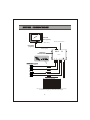
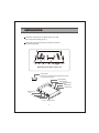
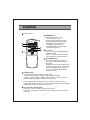
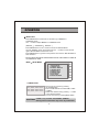
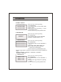
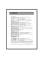
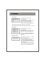
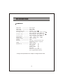
* PLEASE READ CAREFULLY BEFORE USING.
CSW5007Q
MULTI CAMERA CONTROLLER FOR
OBSERVATION MONITOR
(MULTIPLE DISPLAY MODE)
V
T
U
A V-O
A
IR
ce
-r
ei
ve
r
IN
V
A AV-
A1
C
Co
ntr
ol B
A2
C
ox
A3
C
A4
C
ER
W U 2V
PO NTP ~3
I 0V
1
C
D
Doc.Rev (2007/05/07)
* Design and Specifications are subject to change without notice.
Owner's Record
The model and serial numbers are located at the rear.
Record the serial number in the space provided below.
Refer to these numbers whenever you call upon your dealer regarding this product.
Model No.:
Serial No.:
To prevent fire or shock hazard,do not expose the unit to rainor moisture.
To avoid electric shock, do not open the cabinet. Refer servicing to qualified personnel only.
This symbol is intended to alert the
user to the presence of uninsulated
"dangerous voltage" within the product's enclosure that may be of sufficient magnitude to constitute risk of
electric shock to persons.
CAUTION
RISK OF ELECTRIC SHOCK
DO NOT OPEN
CAUTION: TO REDUCE THE RISK OF ELECTRIC SHOCK,
DO NOT REMOVE COVER (OR BACK).
NO USER-SERVICEABLE PARTS INSIDE.
REFER SERVICING TO QUALIFIED SERVICE PERSONNEL.
This symbol is intended to alert the
user to the presence of important
operating and maintenance (servicing)
instructions in the literature accompanying the appliance.
You are cautioned that any changes or modifications not express approved in this manual could void
your authority to operate this equipment.
2
INDEX
FEATURES ----------------------------------------------------------------------- 4
PRECAUTIONS ----------------------------------------------------------------- 5
SYSTEM CONNECTIONS---------------------------------------------------- 6
INSTALLATION ----- ------------------------------------------------------------ 7
OPERATIONS -------------------------------------------------------------------- 8~12
SPECIFICATIONS --------------------------------------------------------------- 13
3
FEATURES
CSW5007Q is designed to be compatible with most voyager
observation monitors and cameras.
Input Voltage DC 10V ~ DC 32V
NTSC / PAL Compatibility
4 Camera Inputs / 1 AV Input / 1AV Output
Multiple Display Mode (Single, Split, Triple, Quad)
Automatic Picture Display (5 Triggering functions)
Auto Scanning function
ON Screen Display Information
4
PRECAUTIONS
Safety
- Use only DC 10V to 32V.
- In case that dust or liquid was soaked into the case, please turn off power and
consult an experienced technician before using.
- Install in a well ventilated area.
Installation
- Do not install the unit in an extremely hot or humid place
(radiator, air duct, etc.) or in a place subject to direct sunlight, excessive dust,
mechanical vibration or shock.
5
MONITOR
(Not supplied)
Remote control sensor
RCA plug or jack (A/V)
RCA CABLE
(supplied)
RCA plug (A/V)
A
V
IR-receiver
A
V
AV-IN
AV-OUT
CSW5007Q
CONTROL BOX
Control Box
CA1
CA2
WIRE COLOR
DESCRIPTION
1
RED
POWER IN + 12VDC
2
BLUE
CAMERA/TRIGGER 1
3
BROWN
CAMERA/TRIGGER 2
REF
4
YELLOW
SPLIT SCREEN TRIGGER
5
BLACK
GROUND-12VDC
6
ORANGE
CA3
CA4
POWER
INPUT
DC10V~32V
CAMERA/TRIGGER 4
7
GREEN
CAMERA/TRIGGER 3
8
PURPLE*
MONITOR TRIGGER OUT
* This wire connects to reverse wire input (trigger 'ON') for monitor display.
Is intended for trigger only, not for main power supply.
6
INSTALLATION
Install the control box on a place which can hold
more weight than 5 Kgs (11 lb).
Fasten the control box with the provided screws as
the drawings below.
Mounting on the floor, console, etc.
Jack Bracket
Fasten the jack bracket with provided screws after
connecting the cameras.
Audio Output
Video Output
Sensor Signal
Input
Audio Input
Video Input
Camera Input
CA1
CA2
CA3
CA4
Power / Trigger Input
7
OPERATION
Remote Control
1
4
* When the trigger signal is activated,
the selected source's image will be
displayed on the monitor screen
automatically. (Please refer to
TRIGGER MODE in SETUP MENU
for further information)
1
5
3
2
POWER button
- Press POWER button to turn
the control box on or off.
2
6
3
- / + button
- Press - / + button to adjust BRIGHT or
CONTRAST level.
- Press - / + button to select the content
of the selected line in each sub menu.
UP / DOWN button
- Press UP / DOWN button to adjust
TILT (PAN) camera position upward or
downward.
(Available only when TILT (PAN) camera
Is connected to CA1, CA2, or CA3 input)
- Press UP/ DOWN button to move the
cursor up or down in SETUP MENU
and each sub menu.
4
CH.SELE button
- Press CH.SELE button to select the display image.
Sequential press shows the image of each camera in turn below.
( CAM1 CAM2 CAM3 CAM4 AUX SPLIT2 SPLIT3
* OSD indicates which image is displayed on the screen.
SPLIT4 )
- Press CH.SELE button to select the items, in which the cursor is in menu.
- Press CH.SELE button to start or stop scanning each display mode sequentially.
Available only when AUTO SCAN in menu is ON.
5
CA1, CA2, CA3, CA4/AV button
- Press CA1, CA2 or CA3 button to select each camera.
- Press CA4 / AV button to select CA4 and press again to select any AV device
connected.
8
OPERATION
6
MENU button
- Press MENU button for less than 0.5 second to go to BRIGHT or
CONTRAST mode.
Use - / + button to adjust BRIGHT or CONTRAST level.
( BRIGHT
CONTRAST
BRIGHT... )
- Press MENU button for over 1 second to enter into SETUP MENU.
Use UP / DOWN to move up and down and use - / + button to move left and
right in SETUP MENU and each sub menu.
- Press MENU button to go back to the previous menu when in SETUP MENU or
each sub menu.
* SELECTABLE OSD MENU DISAPPEARS WITHIN 10 SECONDS IF THERE IS
NO NEW INPUT SIGN.
MENU
SETUP MENU
-- SETUP MENU -1. CAMERA SORT
2. NORMAL / MIRROR
3. TRIGGER MODE
4. SCREEN SPLIT
5. CAMERA NAME
6. SCALE MODE
7. AUTO SCAN
8. ADVANCED MENU
1. CAMERA SORT
CAM1: [NORMAL,SHUTTER, PAN/TILT]
CAM2: [NORMAL,SHUTTER, PAN/TILT]
CAM3: [NORMAL,SHUTTER, PAN/TILT]
- Move cursor up or down by pressing
UP / DOWN button
- Press CH.SELE button to select CAM1, CAM2
or CAM3
- Select each camera sort by pressing - / + button
in the selected camera
- Exit from the menu by pressing MENU button
* CAM4 is only available with NORMAL CAMERA.
CAUTION! * Wrong camera connections may cause any malfunction.
9
OPERATION
2. NORMAL / MIRROR
CAM1: [NORMAL, MIRROR]
CAM2: [NORMAL, MIRROR]
CAM3: [NORMAL, MIRROR]
CAM4: [NORMAL, MIRROR]
- Move cursor up or down by pressing
UP / DOWN button
- Press CH.SELE button to select CAM1, CAM2,
CAM3 or CAM4
- Select normal or mirror by pressing - / + button
in the selected camera
- Exit from the menu by pressing MENU button
3. TRIGGER MODE
- Move cursor up or down by pressing
UP / DOWN button
TRIGGER SOURCE
TIRGGER DELAY
- Press CH.SELE button to select TRIGGER
SOURCE or TRIGGER DELAY menu
TRIGGER SOURCE
TRIGGER1:[CAM1,CAM2,CAM3,CAM4,AUX,SPLIT2,SPLIT3,SPLIT4]
TRIGGER2:[CAM1,CAM2,CAM3,CAM4,AUX,SPLIT2,SPLIT3,SPLIT4]
TRIGGER3:[CAM1,CAM2,CAM3,CAM4,AUX,SPLIT2,SPLIT3,SPLIT4]
TRIGGER4:[CAM1,CAM2,CAM3,CAM4,AUX,SPLIT2,SPLIT3,SPLIT4]
TRIGGER5:[CAM1,CAM2,CAM3,CAM4,AUX,SPLIT2,SPLIT3,SPLIT4]
- Move cursor up or down by pressing
UP / DOWN button
- Press CH.SELE button to select TRIGGER1, 2,
3, 4 or 5
- Select CAM1, CAM2, CAM3, CAM4, AUX,
SPLIT2, SPLIT3 or SPLIT4 by pressing
- / + button in the selected trigger
- Exit from the menu by pressing MENU button
* When the trigger signal is activated, the selected source's image is displayed on
screen.
* TRIGGER PRIORITY : TRIGGER1 > TRIGGER2 > TRIGGER3 >
TRIGGER4 > TRIGGER5
TRIGGER DELAY
TRIGGER1: [ 0 ~20 sec ]
TRIGGER2: [ 0 ~20 sec ]
TRIGGER3: [ 0 ~20 sec ]
TRIGGER4: [ 0 ~20 sec ]
TRIGGER5: [ 0 ~20 sec ]
- Move cursor up or down by pressing
UP / DOWN button
- Press CH.SELE button to select TRIGGER 1, 2,
3, 4 or 5
- Determine each trigger delay time by adjusting
- / + button
- Exit from the menu by pressing MENU button
10
OPERATION
4. SCREEN SPLIT
- Move cursor up or down by pressing
UP / DOWN button
SPLIT 2
- Press CH.SELE button to select SPLIT2,
SPLIT3 or SPLIT4
SPLIT 3
SPLIT 4
- Exit from the menu by pressing MENU button
SPLIT2
SOURCE1: [CAM1,CAM2,CAM3,CAM4]
SOURCE2: [CAM1,CAM2,CAM3,CAM4]
AUDIO : [CAM1,CAM2,CAM3,CAM4]
- Move cursor up or down by pressing
UP / DOWN button
- Press CH.SELE button to select SOURCE1,
SOURCE2 or AUDIO
- Select CAM1, CAM2, CAM3 or CAM4 by
pressing - / + button
SPLIT3
- Exit from the menu by pressing MENU button
SOURCE1:[CAM1,CAM2,CAM3,CAM4]
SOURCE2:[CAM1,CAM2,CAM3,CAM4]
SOURCE3:[CAM1,CAM2,CAM3,CAM4,OFF]
AUDIO
:[CAM1,CAM2,CAM3,CAM4]
- Set up SPLIT3 or SPLIT4 in the same way with
SPLIT2 above
SPLIT4
SOURCE1:[CAM1,CAM2,CAM3,CAM4]
SOURCE2:[CAM1,CAM2,CAM3,CAM4]
SOURCE3:[CAM1,CAM2,CAM3,CAM4,OFF]
SOURCE4:[CAM1,CAM2,CAM3,CAM4,OFF]
AUDIO
* Multiple images can be displayed. (DUAL,
TRIPLE AND QUAD IMAGES)
* Only one audio can be chosen in each SPLIT
mode.
:[CAM1,CAM2,CAM3,CAM4]
5. CAMERA NAME
CAM1: [CAM1
CAM2: [CAM2
CAM3: [CAM3
CAM4: [CAM4
]
]
]
]
- Move cursor up or down by pressing
UP / DOWN button
- Press CH.SELE button to select CAM1, CAM2,
CAM3 or CAM4
- Select letter by pressing - / + button sequentially
- Press CH.SELE button to move to the next letter
- Exit from the menu by pressing MENU button
* Each camera can be named and the camera names are displayed on screen.
11
OPERATION
6. SCALE MODE
CAM1: [OFF, SCALE1, SCALE2]
CAM2: [OFF, SCALE1, SCALE2]
CAM3: [OFF, SCALE1, SCALE2]
CAM4: [OFF, SCALE1, SCALE2]
SCALE 1
SCALE 2
- Move cursor up or down by pressing
UP / DOWN button
- Press CH.SELE button to select CAM1, CAM2,
CAM3, CAM4, SCALE1 or SCALE2
- Select scale OFF, SCALE1 or SCALE2 by
pressing - / + button in each camera
- Exit from the menu by pressing MENU button
* The distance marker of SCALE1 and SCALE2 can be adjusted.
* When the trigger signal is activated, the selected scale is displayed on screen.
7. AUTO SCAN
AUTO SCAN: [ON, OFF]
SCAN CAM1: [0 ~ 20 sec]
SCAN CAM2: [0 ~ 20 sec]
SCAN CAM3: [0 ~ 20 sec]
SCAN CAM4: [0 ~ 20 sec]
SCAN SPLIT2: [0 ~ 20 sec]
SCAN SPLIT3: [0 ~ 20 sec]
SCAN SPLIT4: [0 ~ 20 sec]
- Move cursor up or down by pressing
UP / DOWN button
- Press CH.SELE button to select one of AUTO
SCAN, SCAN CAM1~4, AUX, SPLIT2~4
- Exit from the menu by pressing MENU button
- Set up the scanning time of each SCAN mode
by pressing - / + button if you select ON in
AUTO SCAN
8. ADVANCED MENU
NTSC MODE, PAL MODE
AUTO POWER : [ON, OFF]
- Select NTSC or PAL by pressing - / + button to
select the right video mode
- Select AUTO POWER ON or OFF by pressing
- / + button to select the right operation.
* When "AUTO POWER ON" is selected, the
unit is powered on automatically without using
remote controller.
* When "AUTO POWER OFF" is selected, the
unit is powered on by using remote controller.
- Exit from the menu by pressing MENU button
12
SPECIFICATIONS
CSW5007Q
Power input
......................
Power cons.
.......................
Video system ......................
Camera input (4 CH) .............
A/V output (1 CH) .................
A/V input (1 CH) .....................
Operating temp. ..................
Storage temp. .....................
Ambient condition .................
Vibration .............................
Dimension ...........................
Weight .................................
Supplied acc'y .....................
DC 10V~32V
Max. 24 Watt
NTSC or PAL
Mini DIN 4, 1 Vp-p 72
RCA, Composite video signal, 1Vp-p 72
RCA, Audio signal, 150mV RMS, 47K.
RCA, Composite video signal, 1 Vp-p 72
RCA, Audio signal, 150mV RMS, 47K.
-10 C ~ +50 C ( 14 F ~ 122 F)
-25 C ~ +80 C (-13 F ~ 176 F)
Indoor use only
5.5 G
154 (W) X 105 (D) X 28 (H) mm
6.06 (W) X 4.13 (D) X 1.10 (H) inch
Approx. 0.5 Kg
Power cord 2 M
(1)
Mount Screws
(1)
Jack Bracket
(2)
Remote control
(1)
(1)
RCA cable
Sensor for remote control (1)
Din to voyager Adapter cable (4)
* Design and specifications are subject to change without notice.
13
Printed in Korea