1
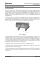
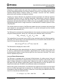
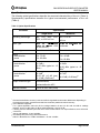
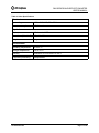
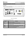
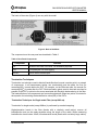
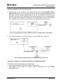
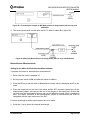
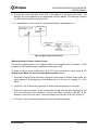
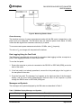
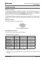
RM3 SERIES BACKREFLECTION METER
USER’S MANUAL
RM3 SERIES
BACKREFLECTION METER
User’s Manual
10112341 Rev 002
Page 1 of 39
RM3 SERIES BACKREFLECTION METER
USER’S MANUAL
Contents
Safety Information, Instructions, and Symbols.......................................................................4
Safety Information ...........................................................................................................4
Classification .......................................................................................................4
Disconnecting from Line Power ...........................................................................4
Line Power Requirements ...................................................................................4
Fuse Type............................................................................................................4
Laser Specifications ............................................................................................4
Safety Instructions...........................................................................................................6
Before Initializing and Operating the Unit ............................................................6
Operating the Unit ...............................................................................................6
Safety Symbols ...............................................................................................................8
Compliance .....................................................................................................................9
CE Compliance....................................................................................................9
FDA-CDRH Compliance ......................................................................................9
CSA / IEC Compliance.........................................................................................9
General Information and Specifications ................................................................................11
General Information ......................................................................................................11
Backreflection Measurements............................................................................12
Loss and Power Measurements ........................................................................12
Output Port ........................................................................................................13
Internal Light Sources........................................................................................13
Hybrid Jumpers..................................................................................................13
Coherence Length .............................................................................................13
Electrical Requirements .....................................................................................13
Key Features .....................................................................................................13
Applications .......................................................................................................14
Standard Accessories........................................................................................14
Optional Accessories .........................................................................................14
Specifications ................................................................................................................15
Getting Started ........................................................................................................................18
Before Initializing and Operating the Unit......................................................................18
Initial Inspection.............................................................................................................18
Operating Environment .................................................................................................19
Altitude...............................................................................................................19
Temperature ......................................................................................................19
Humidity.............................................................................................................19
Voltage ..............................................................................................................19
Storing and Shipping.....................................................................................................19
Claims and Repackaging...................................................................................19
Returning Shipments to JDS Uniphase .............................................................19
Cleaning Connectors.....................................................................................................20
Powering Up the Meter..................................................................................................21
Operating and Maintenance Instructions ..............................................................................22
10112341 Rev 002
Page 2 of 39
RM3 SERIES BACKREFLECTION METER
USER’S MANUAL
Front Panel....................................................................................................................22
Rear Panel ....................................................................................................................23
Termination Techniques................................................................................................23
Termination Techniques for Single-mode Fiber (except 980 nm) ......................23
Termination Techniques for Single-mode (980 nm) and Multimode Fiber .........24
Backreflection Measurements .......................................................................................25
Setting Up the Meter for Backreflection Measurements.....................................25
Measuring Backreflection ..................................................................................26
Backreflection Accuracy and Range..................................................................27
Loss and Power Measurements ....................................................................................27
Setting Up the Meter for Loss and Power Measurements .................................27
Measuring Power...............................................................................................28
Measuring Relative Power (Insertion Loss)........................................................29
Power Accuracy.................................................................................................30
Data Logging Using the Foot Pedal ..............................................................................30
Messages and Symbols ................................................................................................30
Calibrating the Meter .....................................................................................................31
Backreflection Calibration Adjustment ...............................................................32
Power Calibration Adjustment............................................................................32
Maintaining the Meter....................................................................................................33
Cleaning the Unit ...............................................................................................33
Cleaning the Connector Ends............................................................................33
Recharging the Battery......................................................................................34
Replacement of Internal Fuses..........................................................................34
Troubleshooting.................................................................................................34
Programming Guide................................................................................................................37
RS232 Serial Interface ..................................................................................................37
RS232 Pin Assignment......................................................................................37
RS232 Interface Specifications..........................................................................37
RS232-GPIB Converter.................................................................................................39
Left Dip Switch...................................................................................................39
Right Dip Switch ................................................................................................39
Programming Examples ................................................................................................40
RS232 Interface Program Example ...................................................................40
Customized Features and Test Data......................................................................................41
For sales and service information,
contact JDS Uniphase or your local representative.
JDS Uniphase Corporation
570 West Hunt Club Road
Nepean, Ontario, Canada
K2G 5W8
Phone: 613 727-1303
Fax: 613 727-8284
E-mail: [email protected]
10112341 Rev 002
Page 3 of 39
RM3 SERIES BACKREFLECTION METER
USER’S MANUAL
Website: http://www.jdsuniphase.com
Safety Information, Instructions, and Symbols
Safety Information
Classification
The RM Series Backreflection Meter consists of an exposed metal chassis that is connected
directly to earth via a power cord and, therefore, is classified as a Class 1 instrument.
Disconnecting from Line Power
Some of the circuits are powered whenever the unit is connected to the AC power source (line
power). To ensure that the unit is not connected to the line power, disconnect the power cord
from either the power inlet on the unit’s rear panel or from the AC line-power source
(receptacle). The power cord must always be accessible from one of these points. If the unit is
installed in a cabinet, the operator must be able to disconnect the unit from the line power by
the system’s line-power switch.
Line Power Requirements
The RM meter operates from any single-phase AC power source that supplies between 100
and 240 V at a frequency range of 50 to 60 Hz. The maximum power consumption of the RM
meter is 25 VA. The unit can also be operated using its internal 6V DC rechargeable battery.
Fuse Type
The fuse type used by the unit is (5 x 20) mm, 1 A/250 V (fast).
Laser Specifications
Laser specifications are provided in Table 1.
Table 1: Specifications
Parameter
Wavelength
Class
Fiber Type
Single-mode (SM)
Multimode (MM)
980*, 1310, 1480, 1550, 1625,
or 1650 ± 10 nm
850, or 1310 ± 20 nm
1
1
9/125 µm SM(*5/125 µm SM)
50/125 µm MM
62.5/125 µm
MM
Maximum Accessible
Emission Level
-15 dBm
-23 dBm
-25 dBm
Maximum Output Power
-4 dBm
-4 dBm
-4 dBm
Numerical Aperture
0.13 (*0.14)
0.20
0.28
Effective Numerical
Aperture
0.20 (*0.21)
0.27
0.34
10112341 Rev 002
Page 4 of 39
RM3 SERIES BACKREFLECTION METER
USER’S MANUAL
Under the laser classification of the US Food and Drug Administration (FDA) Center for
Devices and Radiological Health (CDRH), the laser contained in the unit is a Class 1 laser.
CLASS 1
LASER PRODUCT
10112341 Rev 002
Page 5 of 39
RM3 SERIES BACKREFLECTION METER
USER’S MANUAL
Safety Instructions
The following safety instructions must be observed whenever the unit is operated, serviced, or
repaired. Failure to comply with any of these instructions or with any precaution or warning
contained in the user’s manual is in direct violation of the standards of design, manufacture,
and intended use of the unit. JDS Uniphase assumes no liability for the customer’s failure to
comply with any of these safety requirements.
Before Initializing and Operating the Unit
Inspect the unit for any signs of damage, and read the user’s manual thoroughly.
Install the unit as specified in the Getting Started section.
Ensure that the unit and any devices or cords connected to it are properly grounded.
Operating the Unit
Warning
To avoid the risk of injury or death, always observe the following precautions
before initializing the unit:
•
To prevent hazardous radiation exposure, use only the controls or
adjustments and perform only procedures specified for the laser source.
•
If using a voltage-reducing autotransformer to power the unit, ensure that
the common terminal connects to the earthed pole of the power source.
•
Use only the type of power cord supplied with the unit.
•
Connect the power cord only to a power outlet equipped with a protective
earth contact. Never connect to an extension cord that is not equipped with
this feature.
•
Willfully interrupting the protective earth connection is prohibited.
•
Never look into the end of an optical cable connected to an optical output
device that is operating. Laser radiation is invisible, and direct exposure can
severely injure the human eye. For more information, see the user’s manual
of the laser source in use.
•
Do not use the unit outdoors.
•
To prevent potential fire or shock hazard, do not expose the unit to any
source of excessive moisture.
•
Do not operate the unit when its covers or panels have been removed.
•
Do not interrupt the protective earth grounding. Any such action can lead to
a potential shock hazard that can result in serious personal injury.
•
Do not operate the unit if an interruption to the protective grounding is
suspected. In this case, ensure that the unit remains inoperative.
•
Use only the type of fuse specified by JDSU as appropriate for this unit. Do
10112341 Rev 002
Page 6 of 39
RM3 SERIES BACKREFLECTION METER
USER’S MANUAL
not use repaired fuses, and avoid any situations that can short-circuit the
fuse.
•
Unless absolutely necessary, do not attempt to adjust or perform any
maintenance or repair procedure when the unit is opened and connected to
a power source.
•
Repairs are to be carried out only by a JDSU qualified technician.
•
Do not attempt any adjustment, maintenance, or repair procedure to the
unit’s internal mechanism if immediate first aid is not accessible.
•
Disconnect the power cord from the unit before adding or removing any
components.
•
Operating the unit in the presence of flammable gases or fumes is
extremely hazardous.
•
Do not perform any operating or maintenance procedure that is not
described in the user’s manual.
•
Some of the unit’s capacitors can be charged even when the unit is not
connected to the power source.
•
If the equipment is used in a manner not specified by the manufacturer, the
protection provided by the equipment may be impaired.
10112341 Rev 002
Page 7 of 39
RM3 SERIES BACKREFLECTION METER
USER’S MANUAL
Safety Symbols
The following symbols and messages can be marked on the unit (Table 2). Observe all safety
instructions that are associated with a symbol.
Table 2: Safety Symbols
Symbol
Description
Laser safety. See the user’s manual for instructions on handling and operating
the unit safely.
See the user’s manual for instructions on handling and operating the unit
safely.
Electrostatic discharge (ESD). See the user’s manual for instructions on
handling and operating the unit safely.
Frame or chassis terminal for electrical grounding within the unit.
Protective conductor terminal for electrical grounding to the earth.
WARNING
The procedure can result in serious injury or loss of life if not carried out
in proper compliance with all safety instructions. Ensure that all
conditions necessary for safe handling and operation are met before
proceeding.
CAUTION
The procedure can result in serious damage to or destruction of the unit if not
carried out in compliance with all instructions for proper use. Ensure that all
conditions necessary for safe handling and operation are met before
proceeding.
10112341 Rev 002
Page 8 of 39
RM3 SERIES BACKREFLECTION METER
USER’S MANUAL
Compliance
CE Compliance
The unit has been designed and tested to comply with directive 73/23/EEC and its subsequent
amendments by the European Community (EC or CE). The directive relates to electrical
equipment designed for use within certain voltage limits. It ensures that electrical equipment is
constructed with good engineering practice in safety matters.
The unit has been designed and tested to comply with directive 89/336/EEC and its
subsequent amendments. The directive relates to electromagnetic compatibility. It demands
that electromagnetic disturbance does not exceed a prescribed level; that the equipment be
immune to a prescribed level of ambient level of interference; that the equipment be protected
against electrostatic discharges; and that the equipment be immune to all electrical shock
wave disturbances. As of 1997, measures have been added to test for fire hazard, electric
shock hazard, and also external exposure to other forms of energy.
The requirements specified by directive 89/336/EEC are as follows. CE compliance requires
that the manufacturer or its authorized representative established within the Community affix
the CE conformity mark to the apparatus or else to the packaging, instructions for use, or
guarantee certificate. The CE conformity mark shall consist of the letters CE as specified and
the figures of the year in which the mark was affixed. This mark should, where appropriate, be
accompanied by the distinctive letters used by the notified body issuing the CE typeexamination certificate. Where the apparatus is the subject of other Directives providing for the
CE conformity mark, the affixing of the CE mark shall also indicate conformity with the relevant
requirements of those other Directives.
FDA-CDRH Compliance
Under the US Food and Drug Administration (FDA) Center for Devices and Radiological Health
(CDRH), the unit complies with the Code of Federal Regulations (CFR), Title 21, Subchapter J,
which pertains to laser safety and labeling. See http://www.fda.gov/cdrh/radhlth/cfr/21cfr10001050.pdf for more information.
CSA / IEC Compliance
The unit complies with certain standards of the Canadian Standards Association (CSA) and
the International Electrotechnical Commission (IEC).
The unit is in Installation Category (Overvoltage Category) II under IEC 664. IEC 664 relates to
impulse voltage levels and insulation coordination. The particular category is defined as: local
level, appliances, portable equipment, etc, with smaller transient overvoltages than Installation
Category (Overvoltage Category) III.
The unit is in the Pollution Degree 2 category under IEC 1010-1 and CAN/CSA-C22.2 No.
1010.1. The IEC standard on Safety Requirements for Electrical Equipment for Measurement,
Control, and Laboratory Use relates to insulation coordination. The CSA standard is on Safety
Requirements for Electrical Equipment for Measurement Control, and Laboratory Use, Part I:
General Requirements. The Pollution Degree 2 category is defined as follows: “Normally only
10112341 Rev 002
Page 9 of 39
RM3 SERIES BACKREFLECTION METER
USER’S MANUAL
non-conductive pollution occurs. Occasionally, however, a temporary conductivity caused by
condensation must be expected.”
10112341 Rev 002
Page 10 of 39
RM3 SERIES BACKREFLECTION METER
USER’S MANUAL
General Information and Specifications
General Information
This user’s manual for the RM3 Series Backreflection Meter contains complete operating
instructions. The RM meter can be ordered as a single-mode or multimode model. Software is
bundled with the meter; for information on using the software, see the Multiple Connector Test
System Software User’s Manual (document SD000318). The inspection report and a
description of any customer-requested information are found in Customized Features and
Test Data section.
The RM meter (Figure 1) is a portable, direct-display instrument that measures backreflection,
loss, and power of single-mode and multimode fiberoptic connectors, components, and
systems. The RM meter is supplied with one or two internal laser sources for operation at 850,
980,1310, 1480, 1550, 1625, or 1650 nm (not all combinations are available).
Figure 1: RM Meter
An important feature of the RM meter is the FC/APC ultra-low backreflection connector at its
output port (SC/APC connector also offered). By switching hybrid jumpers connected to the
FC/APC connector, the user can select the connector type required for a measurement quickly
and easily, without limiting the backreflection range of the meter. The RM meter is supplied
with a hybrid measurement jumper to be used exclusively for measurements and a hybrid
calibrated jumper to be used exclusively for calibrations.
The RM meter can be operated using an internal 6 V DC rechargeable battery.
The RM meter includes a convenient foot pedal, enabling the user to trigger the meter to send
measurement data to a computer or printer.
The RM meter operates over the RS232 serial interface. Wherever the IEEE 488 GPIB parallel
interface is mentioned, it is achieved via a RS232-to-GPIB converter that can be purchased as
an accessory.
10112341 Rev 002
Page 11 of 39
RM3 SERIES BACKREFLECTION METER
USER’S MANUAL
Backreflection Measurements
Reflections in optical systems can come from a number of sources. Primary sources include
the fiber (Rayleigh backscatter) and Fresnel reflections that occur at the planar junction of two
materials having different refractive indices, for example, connector and fiber endfaces,
splices, bulk optic interfaces, and detector surfaces.
Typically only Fresnel reflections are significant because transmitters are relatively insensitive
to distributed reflections such as Rayleigh backscatter. Backreflection caused by Rayleigh
backscatter varies with the length and type of fiber, and is only significant when measuring
components with backreflections below -40 dB or with very long pigtails (multimode). However,
Rayleigh backscatter can be a large contributor to backreflection in installed systems or when
using long fiber.
The internal switch and coupler of the RM meter enable the meter to measure the internal light
source signal (Pin), the signal offset with no light (Pdark), and the total signal level from internal
and external backreflections (Pbr).
The RM meter first calculates the total backreflection from internal and external sources (BR tot),
using the following equation, where CAL is the factory-set calibration factor of the meter:
BRtot = 10 log (Pbr - Pdark)/(Pin - Pdark) - CAL
[dB]
The backreflection from external sources (BR) is then calculated using the following equation,
where BR0 is the stored value of the total backreflection up to the device under test (DUT), and
User CAL is the user-set calibration factor:
BR = 10 log (10BRtot/10 - 10 BR0/10) + User CAL
[dB]
The RM meter then displays the value of BR.
The BR measurement takes approximately one second to complete. Before this is done, the
Pin and Pdark measurements are completed in approximately four seconds, during which time
the backreflection display is locked and the light from the output port is blocked. The values
are then updated every minute.
Loss and Power Measurements
The RM meter is equipped with a front-panel InGaAs detector for relative power (loss) and
absolute power measurements. (Absolute power is referred to as power in this manual; relative
power is always referred to as relative power.) Because the meter is capable of storing the
dark signal from the detector, high-accuracy power measurements as low as -80 dBm for the
single mode model (and –60 dBm for the multimode model) can be obtained.
When making power measurements, the RM meter first measures two signals: the total signal
level (Itot) and the dark signal from the detector (ID). The RM meter then calculates the power
measurement using the following equation, where CAL is the factory-set calibration factor and
User CAL is the user-set calibration factor:
P = 10 log (Itot - ID) + CAL + User CAL
10112341 Rev 002
[dB]
Page 12 of 39
RM3 SERIES BACKREFLECTION METER
USER’S MANUAL
Output Port
The output port of the RM meter is equipped with an ultra-low backreflection APC connector.
To prevent damage to the output port connector, a measurement jumper must be used for all
measurements, even for measuring a component with an APC connector.
Internal Light Sources
The RM meter can be equipped with two internal laser sources. These are thermoelectrically
cooled for added stability and are modulated at 10 kHz. Fast changes in ambient temperature
can cause a source to become unstable. If this occurs, the meter automatically switches to a
measuring mode in which Pin and Pdark are measured more frequently than every minute and
the message “Source Unstable” is displayed. The light source power is monitored, and the
meter returns to the standard measurement mode when the source has stabilized.
Hybrid Jumpers
The RM meter is supplied with a hybrid measurement jumper and a hybrid calibrated jumper.
The measurement jumper has an APC connector at the input end. The other end on the
standard measurement jumper is PC, but by changing measurement jumpers this end is userselected, to be compatible with the input connector of the DUT. The calibrated jumper has an
APC connector at the input end and a PC connector at the output end.
Use the measurement jumper for measurement purposes only; use the calibrated jumper for
calibration purposes only. The calibrated jumper has a label attached to it identifying it as the
calibrated jumper.
Coherence Length
Reflected light from multiple reflections can change the backreflection measured by the
RM meter. This variation typically shows up as noise or drift in the signal. The internal light
source is designed to have low coherence length (typically less than 10 cm). Thus,
interference effects are typically seen only between very closely spaced components such as
non-contacting connectors.
Electrical Requirements
The RM meter is supplied with a rechargeable battery. When fully charged, the battery
provides up to eight hours of operation at room temperature. For laboratory use, use the
RM meter with the power cord. The letter B is shown on the RM meter front panel display when
the battery power is low.
Key Features
•
•
•
•
•
•
Backreflection measurements to -75 dB for single mode model (-40 dB for multi mode
model)
Power measurements to -80 dBm for single mode model (-60 dBm for multi mode model)
Convenient foot pedal for data logging
MCTS application software
Built-in light sources at 850, 980, 1310, 1480, 1550, 1625, or 1650 nm
Compensation for extraneous backreflection for accurate backreflection measurements
10112341 Rev 002
Page 13 of 39
RM3 SERIES BACKREFLECTION METER
USER’S MANUAL
•
•
•
•
User-calibration mode
RS232 serial and IEEE 488 GPIB parallel interface
Convenient data logging via serial port to a computer or serial printer
Direct display of measured backreflection, power, or insertion loss
Applications
•
•
•
•
Connector backreflection and loss testing
Component testing
Installation verification
Quality assurance (QA) acceptance testing
Standard Accessories
•
•
•
•
•
•
•
•
•
•
•
AC power cord (country specific)
Laser sources specified when ordered
FC/PC-FC/APC or SC/PC-SC/APC hybrid measurement jumper
FC/PC-FC/APC or SC/PC-SC/APC hybrid calibrated jumper
FC-type (or SC-type) detector adapter
Detector cap
Foot pedal
MCTS software and user’s manual
User’s manual
Carrying case (for field use)
Certificate of Compliance (NIST Traceability Report available on request)
Optional Accessories
•
•
•
Variety of detector adapters
Measurement jumpers with various user-selected connectors
RS232-to-GPIB converter
10112341 Rev 002
Page 14 of 39
RM3 SERIES BACKREFLECTION METER
USER’S MANUAL
Specifications
The following optical specifications describe the warranted characteristics of the unit ( Table 3).
Supplementary specifications describe the typical non-warranted performance of the unit
(Table 4).
Table 3: Optical Specifications
Parameter
Specification
Single-mode
Operating wavelength
Fiber Type
Multimode
980, 1310, 1480, 1550, 850, 1310 nm
1625, or 1650 ±10 nm
±20 nm
9/125 µm single-mode
50/125 µm or 62.5/125 µm
(5/125 µm Flexcor* 1060 multimode
for the 980 nm)
Detector type
2 mm diameter InGaAs
3 mm diameter InGaAs
Range
backreflection
power
0 to -75 dB
0 to -80 dBm
0 to –40 dB1
3 to -60 dBm
Absolute accuracy
backreflection
power
Relative accuracy
backreflection
power
Output connector type
±1.0 dB2,3
±1.0 dB4
±0.25 dBm typical at -10 ±0.25 dBm typical at -10
dBm5,6
dBm6
±0.4 dB3
±0.7 dB4
±0.05 dB (<5 dB loss), ±0.15 dB (>5 dB loss)6,7
±0.15 dB (>5 dB loss)5
Panel-mounted,
low-backreflection APC
Remote interface
1
2
3
4
5
6
7
RS232 or IEEE 488 (GPIB)
Reduced backreflection accuracy in the last 10dB of range based on termination effectiveness. Depending on
the measurement setup, measurements with lower levels are possible at reduced accuracy.
User-calibration supported.
For a typical application, add ±0.4 dB for readings between -60 and -67 dB. Add ±0.8 dB for readings
between -67 and -72 dB. Add ±1.5 dB for readings between -72 and -75 dB.
Following the user-calibration procedure at the recommended interval. For simple reflections, such as flat-end
connectors.
Add ±0.1 dB between -70 and -80 dBm.
Immediately after performing a dark measurement.
Add ±0.1 dB between 0 to 3 dBm and between –35 and –40 dBm.
10112341 Rev 002
Page 15 of 39
RM3 SERIES BACKREFLECTION METER
USER’S MANUAL
*
Flexcor is a trademark of CorningR.
10112341 Rev 002
Page 16 of 39
RM3 SERIES BACKREFLECTION METER
USER’S MANUAL
Table 4: Other Specifications
Electrical
Input voltage
100 to 240 V AC, 50 to 60 Hz
Power consumption
25 VA maximum
Physical
Display
16-character LCD
Dimensions (W x H x D)
26 x 11 x 26 cm
Weight
4 kg
Environmental
Operating temperature
0 to 40 °C
Storage temperature
-40 to 70 °C
Humidity
maximum 95% RH from 0 to 40 °C
Equipment positioning
transportable
10112341 Rev 002
Page 17 of 39
RM3 SERIES BACKREFLECTION METER
USER’S MANUAL
Getting Started
The RM3 Series Backreflection Meter consists of the meter, an AC power cord, two jumpers,
and a foot pedal.
Before Initializing and Operating the Unit
Inspect the unit for any signs of damage.
Read the user’s manual thoroughly, and become familiar with all safety symbols and
instructions to ensure that the unit is operated and maintained safely.
If the unit is used in a manner not specified by JDS Uniphase, the protection provided by
the unit may be impaired.
Initial Inspection
Warning
To avoid electrical shock, do not initialize or operate the unit if it bears any sign
of damage to any portion of its exterior surface, such as the outer cover or
panels.
Check that the unit and contents are complete:
1. Inspect the shipping container for any indication of excessive shock to the contents, and
inspect the contents to ensure that the shipment is complete.
2. Inspect the unit for structural damage that can have occurred during shipping.
3. Connect the unit to the power source using the power cord provided.
4. Set the power switch to ON to initialize the RM meter, and observe the power-up
sequence. The model number of the meter is displayed. Internal measurements of P in and
Pdark are made. The message “Stabilizing” is displayed as the light source stabilizes. The
backreflection value (BR) of the front panel connector is measured and displayed.
5. Set the power switch to OFF and disconnect the RM meter.
6. Connect the foot pedal to the Log port at the back of the meter if you intend to send data
from the meter to a computer or printer.
7. Keep the packaging.
Immediately inform JDS Uniphase and, if necessary, the carrier if the contents of the shipment
are incomplete, if the unit or any of its components are damaged or defective, or if the unit
does not pass the initial inspection.
10112341 Rev 002
Page 18 of 39
RM3 SERIES BACKREFLECTION METER
USER’S MANUAL
Operating Environment
In order for the unit to meet the warranted specifications, the operating environment must meet
the following conditions for altitude, temperature, humidity, and voltage.
Altitude
The unit can be operated at an altitude up to 2000m.
Temperature
The unit can be operated in the temperature range of 0 to 40 °C.
Humidity
The unit can be operated in environments with up to 95% humidity (0 to 40 °C). Do not expose
it to any environmental conditions or changes to environmental conditions that can cause
condensation to form inside the unit.
Voltage
The main supply voltage fluctuations are not exceeding ±10% of the nominal voltage.
Warning
•
Do not use the unit outdoors.
•
To prevent potential fire or shock hazard, do not expose the unit to any
source of excessive moisture.
Storing and Shipping
To maintain optimum operating reliability, do not store the unit in locations where the
temperature falls below -40 °C or rises above 70 °C. Avoid any environmental condition that
can result in internal condensation. Ensure that these temperature and humidity requirements
can also be met whenever the unit is shipped.
Claims and Repackaging
Immediately inform JDS Uniphase and, if necessary, the carrier, if
•
•
•
The contents of the shipment are incomplete
The unit or any of its components are damaged or defective
The unit does not pass the initial inspection
In the event of carrier responsibility, JDS Uniphase will allow for the repair or replacement of
the unit while a claim against the carrier is being processed.
Returning Shipments to JDS Uniphase
JDS Uniphase only accepts returns for which an approved Return Material Authorization
(RMA) has been issued by JDS Uniphase sales personnel. This number must be obtained prior
to shipping any material to JDS Uniphase. The owner’s name and address, the model number
and full serial number of the unit, the RMA number, the original JDSU sales order number, the
10112341 Rev 002
Page 19 of 39
RM3 SERIES BACKREFLECTION METER
USER’S MANUAL
invoice number, and an itemized statement of claimed defects must be included with the return
material.
Ship return material in the original shipping container and packing material. If these are not
available, packaging guidelines are as follows:
1. Cover the front panel with foam to prevent damage.
2. Wrap the unit in anti-static packaging. Use anti-static connector covers.
3. Pack the unit in a reliable shipping container.
4. Use enough shock-absorbing material (10 to 15 cm) to cushion the unit and prevent it from
moving inside the container. Pink poly anti-static foam is the best material.
5. Seal the shipping container securely.
6. Clearly mark FRAGILE on its surface.
7. Always provide the model and serial number of the unit and, if necessary, the RMA number
on any accompanying documentation.
8. In order to ship the unit please contact the JDS RMA department at 613-727-1303.
Cleaning Connectors
Caution
•
Connecting damaged or dirty fibers to the unit can damage the connectors
on the unit.
•
Never force an optical connector. Some connectors have a ceramic ferrule
that can easily be broken.
Optical cable ends need to be cleaned before using them with the unit.
The following items are required for cleaning:
•
•
•
•
Filtered compressed air or dusting gas (for example, Tech Spray Envi-Ro-Tech Duster
1671 gas, available from http://www.techspray.com)
Lint-free pipe cleaners (for example, from 3M1) or lint-free swab
Lint-free towels (for example, 10 x 10 cm or 4 x 4 in HydroSorb III wipers, available from
http://www.focenter.com)
Optical grade isopropyl alcohol or optical grade 200° ethanol (do not use rubbing alcohol,
which contains 30% water)
To clean the connectors:
1
3M is a trademark of 3M.
10112341 Rev 002
Page 20 of 39
RM3 SERIES BACKREFLECTION METER
USER’S MANUAL
1. Blow the sleeve with filtered compressed air (Figure 2).
sleeve
ferrule
Figure 2: Connector Cleaning (connector type can vary)
2. Apply optical grade isopropyl alcohol or optical grade ethanol (do not use rubbing alcohol)
to a small area of a lint-free towel and rub the end of the ferrule over the wet area.
3. Wipe the ferrule on a dry area of the lint-free towel.
4. Using the dusting gas or compressed air, blow the end of the ferrule.
5. Apply the alcohol or ethanol to a lint-free pipe cleaner or swab and wipe off the remaining
parts of the connector.
6. With the other end of the pipe cleaner or swab, dry the areas cleaned.
7. Using the dusting gas or compressed air, blow the areas cleaned.
Powering Up the Meter
To power up the meter:
1. Connect the meter to an AC power source using the power cord provided.
2. Set the power switch to ON to initialize the RM meter, and observe the power-up
sequence: The model number of the meter is displayed. Internal measurements of P in and
Pdark are made. The message “Stabilizing” is displayed as the light source stabilizes. The
backreflection value (BR) of the front panel connector is measured and displayed.
10112341 Rev 002
Page 21 of 39
RM3 SERIES BACKREFLECTION METER
USER’S MANUAL
Operating and Maintenance Instructions
Front Panel
The front of the meter (model RM3750) is shown in Figure 3 and described inTable 5. Not all
RM3 Series meters are exactly as shown.
Figure 3: Front of the Meter
Table 5: Front Panel Operating Keys and LEDs
Key/LED
Description
ON / OFF
Power on ON / OFF switch.
BR
Sets the meter to Backreflection measurement mode.
STORE BR0
Stores the BR0 value used in backreflection measurements and toggles
the key lamp on and off.
POWER
Sets the meter to Power and Relative Power measurement modes.
STORE ID
Stores the ID value used in dark measurements.
λ
Selects one of the two laser sources.
10112341 Rev 002
Page 22 of 39
RM3 SERIES BACKREFLECTION METER
USER’S MANUAL
Rear Panel
The back of the meter (Figure 4) can vary with the model.
-
25 VA max
Fuse 1A/250V
Figure 4: Back of the Meter
The components on the rear panel are described in Table 6.
Table 6: Rear Panel Components
Component
Function
CAL
Access to the User CAL value, for calibration purposes.
LOG
Foot pedal jack for data logging.
RS232C
RS232 serial interface port.
Termination Techniques
Termination is a technique used to block all backreflections beyond a certain point in a network
of components. In all measurement testing, two terminations must be made: the first (for
measuring BR0) is made before the DUT, for example, on the RM meter side; the second (for
measuring BRtot) is made after the DUT. Both termination points need to be made as close as
possible to the DUT to minimize the errors associated with Rayleigh backscattering in the fiber.
The backreflection of all components and connections between these two points is included in
the equation for calculating the backreflection value (BR) of the DUTs.
Termination Techniques for Single-mode Fiber (except 980 nm)
Termination for single-mode (except 980nm) is performed by mandrel wrapping.
High-attenuation bends in the fiber (bends with a relatively small radius) remove all
backreflection and can be made anywhere along the length of the cable. When measuring
backreflection levels below -60 dB, low-attenuation bends (bends with a relatively large radius)
10112341 Rev 002
Page 23 of 39
RM3 SERIES BACKREFLECTION METER
USER’S MANUAL
need to be made just before the high-attenuation bends in order to offset the small amount of
reflection caused by the high-attenuation bends.
1. Using the size of rod specified in the Inspection Report (see the Customized Features
and Test Data section), wind the cable around the rod until the reading displayed on the
RM meter no longer changes (approximately six turns). The diameter of the rod must be
suitable for the type of fiber connected to the output port jumper and for the wavelength in
use. To minimize any memory of the bends in the cable jacket, do not pull on the cable
while winding, and occasionally wind the cable in the opposite direction (figure 5a).
Figure 5a: Terminating the Jumper for BR Measurement for Single-mode (except 980nm)
2. The second termination is made after the DUT in order to obtain Brtot (figure 6a).
Figure 6a: Measuring Backreflection for Single-mode (except 980 nm)
Termination Techniques for Single-mode (980 nm) and Multimode Fiber
Termination is performed by using index-matching gel.
1. Apply index-matching gel directly to the fiber end (figure 5b).
2. After measuring BR0, clean the connector end in accordance with the Cleaning
Connectors section.
10112341 Rev 002
Page 24 of 39
RM3 SERIES BACKREFLECTION METER
USER’S MANUAL
Figure 5b: Terminating the Jumper for BR Measurement for Single-mode (980 nm only) and
Multimode
3. The second termination is made after the DUT in order to obtain Brtot (figure 6b).
Figure 6b: Measuring Backreflection for Single-mode (980 nm only) and Multimode
Backreflection Measurements
Setting Up the Meter for Backreflection Measurements
To prepare the meter for backreflection measurements:
1. Ensure that the meter is powered off.
2. Set the power switch to ON, and allow the meter to stabilize.
3. Press the BR key to set the meter to Backreflection mode, which is displayed as BR on the
meter.
4. Clean the output port on the front of the meter and the APC connector (green boot) of the
measurement jumper, and connect this end of the jumper to the output port. Ensure that
you are using the measurement jumper and not the calibration jumper, which is labeled as
such. The output connector of the measurement jumper is user-selected and must be
compatible with the input connector of the DUT.
For each wavelength at which measurements are to be made:
5. Press the λ key to select the required wavelength.
10112341 Rev 002
Page 25 of 39
RM3 SERIES BACKREFLECTION METER
USER’S MANUAL
6. Terminate the measurement jumper just before the output connector, and hold the
termination point steady (figure 5a for single-mode(except 980nm), and figure 5b for singlemode(980nm) and multimode).
NOTE
The termination technique is different depending on the type of the RM Meter used :
single-mode (except 980 nm), single-mode (980nm) or multimode.
Please refer to the Termination Techniques section above.
7. Press the Store BR0 key. The key lamp lights to indicate that the background backreflection
has been stored. The BR0 value is used in the calculation of the DUT backreflection at the
selected wavelength.
8. Remove the termination.
Measuring Backreflection
To measure backreflection and power from a unit after setting up the meter (see the Setting
Up the Meter for Backreflection Measurements section):
1. Clean the output connector of the measurement jumper and the input connector of the
DUT, and mate the two.
2. Press the λ key to select the wavelength at which the measurement is to be made.
3. Terminate the measurement jumper immediately after the DUT, and hold the termination
point steady. The meter displays the backreflection between the two termination points that
is caused by the fiber, all connections, and the DUT. This area is shown within the dashed
line in Figure 6a for single-mode (except 980nm), and in Figure 6b for single-mode
(980nm) and multimode.
4. If necessary, terminate the fiber for BR0 again just before the DUT to eliminate the
backreflection caused by the fiber and all connections before the DUT.
5. Press the Store BR0 key. The key lamp lights to indicate that the function is on.
6. If the backreflection setup has been done previously (BR 0 light is on), press the BR 0 button
to delete the currently stored BR0 value. The BR0 light turns off.
7. Press λ and repeat step 6 to delete the stored BR0 value for another wavelength.
8. Release the termination. The meter now displays the backreflection of the DUT only.
9. If a measurement is to be made at a second wavelength, repeat steps 1 through 8.
The small amount of reflections that BR 0 represents can be polarization sensitive, and multiple
reflections can cause interference effects that can make the reflections very sensitive to
10112341 Rev 002
Page 26 of 39
RM3 SERIES BACKREFLECTION METER
USER’S MANUAL
temperature. To ensure accurate backreflection measurements below -65 dB (-25 dB for
multimode):
1. Perform the BR0 measurement at least once per shift.
The measured backreflection is affected by losses that can occur between the meter and the
DUT. To compensate for these losses, measure the total amount of loss between the output of
the measurement hybrid jumper and the input of the DUT (see the Loss and Power
Measurements section). Double this value and add it to the backreflection value displayed on
the meter. In the following example, the total loss between the meter and the DUT is 2.0 dB,
and the displayed backreflection is -29 dB:
BR = -29 dB + (2 x 2.0 dB) = -25 dB
Backreflection Accuracy and Range
The absolute accuracy of backreflection measurements made with the meter is dependent on
the level of backreflection to be measured.
The backreflection measurement range is restricted by the BR0 level. The meter can measure
backreflection levels 15 dB below BR0 to a maximum of -75 dB (-40dB for multimode). For
example, if BR0 is -40 dB, the minimum backreflection of the DUT that can be measured is -55
dB.
An asterisk (*) is displayed near the range limit (last 5 dB of range if using BR0, below -60 dB
otherwise) to indicate that the setup and measurement procedures described in the previous
two sections must be followed carefully to ensure accurate results.
Absolute accuracy specifications are dependent upon the accuracy of the RM meter
calibration, so a calibration check needs to be performed periodically (see the Calibrating the
Meter section).
Loss and Power Measurements
Setting Up the Meter for Loss and Power Measurements
To prepare the meter for loss and power measurements:
1. Ensure that the RM meter is powered off.
2. Set the power switch to ON, and allow the RM meter to stabilize.
3. Clean the output port on the front of the meter and the FC/APC connector (green boot) of
the measurement jumper, and connect this end of the jumper to the output port. Ensure
that you are using the measurement jumper and not the calibration jumper, which is
labeled as such.
For each wavelength at which measurements are to be made:
4. Press the λ key to select the required wavelength.
10112341 Rev 002
Page 27 of 39
RM3 SERIES BACKREFLECTION METER
USER’S MANUAL
5. Attach the appropriate detector adapter to the detector on the front of the meter.
6. Connect the output connector of the measurement jumper to the detector adapter. This
end of the measurement jumper is user-selected and must be compatible with the input
connector of the DUT.
7. Press the Power key to set the meter to Power mode. When in Power mode, the meter
displays P at the beginning of the reading, and no “rel” is displayed, for example, P = -9
dBm.
8. Press and hold the Power key until the display on the meter clears.
9. Release the Power key. The display reads 0.00 dB, and the loss of the measurement
jumper is subtracted from the DUT loss or power measurements to be made (Figure 7).
Figure 7: Loss and Power Measurements
For loss and power measurements below -50 dBm:
10. Ensure that the detector is covered, for example, that the detector cap is on or the output
connector is connected to the detector. This dark measurement current is subtracted from
future loss and power measurements.
11. Press the Store ID key. The key lamp lights to indicate that the user-stored value of ID (the
dark signal from extraneous sources) is used to calculate the DUT loss or power. If the
detector is not sufficiently covered, the message “Too Much Light” is displayed. If the ID
value is not stored before a measurement is made, the last value stored is used.
Measuring Power
In Power mode, absolute power measurements are displayed in dBm. To make a power
measurement of a DUT after performing the setup steps in the Setting Up the Meter for Loss
and Power Measurements section:
1. Press the Power key to set the meter to Power mode.
2. Press the λ key to select the wavelength at which the measurement is to be done.
3. Clean the output connector of the measurement jumper and the input connector of the
DUT, and connect the two connectors.
10112341 Rev 002
Page 28 of 39
RM3 SERIES BACKREFLECTION METER
USER’S MANUAL
4. Connect the output connector of the DUT to the detector on the front of the meter. The
detector must be equipped with the appropriate detector adapter. The RM meter displays
the DUT absolute power output (Figure 8).
5. If a measurement is to be made at a second wavelength, repeat steps 2 to 4.
Figure 8: Measuring Absolute Power
Measuring Relative Power (Insertion Loss)
The value for relative power is the negative value of the insertion loss, for example -31 dB
instead of 31 dB. Relative power is displayed by the meter in dB.
To make a relative power measurement of a DUT after performing the setup steps in the
Setting Up the Meter for Loss and Power Measurements section:
1. Press the Power key to set the meter to Relative Power mode. In Relative Power mode, the
meter displays P at the beginning of the reading and rel at the end, for example, P = -0.15
dB rel.
2. Press the λ key to select the wavelength at which the measurement is to be made.
3. Clean the output connector of the measurement jumper and the input connector of the
DUT, and connect the two connectors. Connect the output connector of the DUT to the
detector on the front of the meter. The meter displays the loss due to the DUT (Figure 9).
4. Press the λ key to measure and display the loss at another wavelength.
10112341 Rev 002
Page 29 of 39
RM3 SERIES BACKREFLECTION METER
USER’S MANUAL
Figure 9: Measuring Relative Power
Power Accuracy
The absolute accuracy of power measurements made with the RM meter is dependent on the
power level to be measured. The RM meter does not measure power levels below -50 dBm
unless the dark signal from extraneous sources (ID) is stored.
To ensure accurate power measurements below -65 dBm, store ID frequently.
The value of ID can change with temperature fluctuations.
Data Logging Using the Foot Pedal
The RM meter is supplied with a foot pedal for convenient data logging to either a computer or
printer. Data logging operates at a baud rate of 2400.
To use the foot pedal:
1. Ensure the computer or printer is connected to the RS232C or IEEE 488 (GPIB) port at the
back of the meter.
2. If the foot pedal is not already operational, connect the foot pedal plug to the Log jack on
the rear panel of the meter.
3. Press the foot pedal. The message “Log” appears on the right-hand side of the front-panel
display, and the most recent measurements made are sent to the computer or printer
through the RS232 serial or IEEE 488 (GPIB) port.
Messages and Symbols
The messages and symbols displayed by the RM meter are described in Table 7.
Table 7: RM Meter Display Messages and Symbols
Display
RMXXXXB
VERY.Y
10112341 Rev 002
Description
Displayed momentarily during the power-up sequence and indicates
Page 30 of 39
RM3 SERIES BACKREFLECTION METER
USER’S MANUAL
Display
Description
the model number (XXXX) and the software version (Y.Y).
STABILIZING
Displayed momentarily during the power-up sequence as the initial
internal reference measurements are made.
BR=-XX.XdB
Backreflection mode.
P=-XX.XXdBm
Power mode.
P=-XX.XXdB rel
Relative Power mode.
*
Displayed when the BR value is within the last 5 dB of range if using
BR0, or from -60 to -75 dB if not using BR0.
B
Low battery.
<
P or BR is lower than the minimum value.
>
P is greater than the maximum value.
BRo STORED=-XX.X
Displayed momentarily when the BR value (-XX.XdB) is being stored
as BR0.
ID STORED
Displayed momentarily when measuring I D.
TOO MUCH LIGHT
Displayed momentarily if the I D value is too high.
INPUT LOW
Displayed momentarily when the laser power is too low.
INPUT HIGH
Displayed momentarily when the laser power is too high.
SOURCE UNSTABLE
Displayed momentarily when the laser power is unstable.
1.3 BR CAL= X.X
Indicates the backreflection user calibration value at 1.3 µm (1.3 µm
is taken as an example).
1.5 BR CAL= X.X
Indicates the backreflection user calibration value at 1.5 µm.
1.3 PW CAL= X.XX
Indicates the power user calibration value at 1.3 µm.
1.5 PW CAL= X.XX
Indicates the power user calibration value at 1.5 µm.
Calibrating the Meter
Caution
Devices with malfunctioning lasers must be returned to the manufacturer for
calibration.
Annual calibration of the meter by JDS Uniphase is recommended. This section outlines how
to do periodic adjustments to ensure the accuracy of backreflection, loss, and power
measurements. Use only the calibrated jumper for all calibration procedures.
10112341 Rev 002
Page 31 of 39
RM3 SERIES BACKREFLECTION METER
USER’S MANUAL
Backreflection Calibration Adjustment
The RM meter has a factory-set backreflection calibration value (User CAL) that compensates
for the typical loss resulting from a connection to the front-panel FC/APC connector. This value
appears in the Inspection Report (see the Customized Features and Test Data section).
To perform a backreflection calibration adjustment:
1. Press the BR key to set the RM meter to Backreflection mode, which is displayed as BR on
the meter.
2. Clean and connect the APC connector (green boot) of the calibrated jumper to the output
port of the RM meter.
3. Press the λ key to select the wavelength at which the calibration check is to be performed.
Choose either wavelength, as you will check both.
4. Clean the output connector of the calibrated jumper. The backreflection value is displayed.
The value displayed on the RM meter must match the reference value that appears in the
inspection report and on the label of the calibrated jumper. If these values do not match,
ensure that the FC/APC connector is properly connected to the RM meter, and clean all the
connectors. If the values still do not match to within ±0.3 dB, adjust the value of User CAL. The
CAL key is located on the rear panel of the RM meter.
To adjust the value of User CAL:
1. Use a screwdriver or an appropriately narrow object to press the CAL key on the back of
the RM meter. The last User CAL value stored is displayed on the RM meter.
2. Press and hold the Store BR0 key to scroll to the required value in 0.1 dB increments.
3. Press the CAL key to store the User CAL value and return the RM meter to the
backreflection measurement display.
Perform calibration adjustment for the second wavelength:
1. Repeat the calibration adjustment procedure for the second wavelength.
Power Calibration Adjustment
To perform a power calibration adjustment:
1. Press the Power key to set the RM meter to Power mode. In Power mode, the meter
displays P at the beginning of the reading, and the value displayed is not followed by “rel”.
An example is P = -9 dBm.
2. Clean and connect the FC/APC connector (green boot) of the calibrated jumper to the
output port of the meter.
10112341 Rev 002
Page 32 of 39
RM3 SERIES BACKREFLECTION METER
USER’S MANUAL
3. Press the λ key to select the wavelength at which the calibration check is to be performed.
Choose either wavelength, as you will check both.
4. Measure the power from the output of the calibrated jumper, using a high-accuracy,
calibrated power meter.
5. Clean the output connector of the calibrated jumper, and connect it to the detector on the
front panel of the RM meter. The value displayed on the RM meter must match the value
measured by the power meter to within ±0.3 dBm.
If the values do not match to within ±0.3 dBm, adjust the value of User CAL:
1. Use a screwdriver or an appropriately narrow object to press CAL. The last User CAL value
stored is displayed on the meter.
2. Press and hold the Store ID key to scroll to the required value in 0.01 dBm increments.
3. Press the CAL key to store the User CAL value, and return the meter to the power
measurement display.
4. Repeat the calibration adjustment procedure (steps 1 to 3) for the second wavelength.
Maintaining the Meter
Caution
Devices with malfunctioning lasers must be returned to the manufacturer for
repair.
Cleaning the Unit
1. Unplug the unit from the line power.
2. Clean the enclosure with a damp cloth.
3. DO NOT plug the unit back until it is completely dry.
Cleaning the Connector Ends
Clean all connector ends with a lint-free tissue and alcohol before every mating. See the
Cleaning Connectors section.
1. Loosen the retaining screws of the connector panel, and remove the panel carefully to
access the internal connectors (Figure 10).
10112341 Rev 002
Page 33 of 39
RM3 SERIES BACKREFLECTION METER
USER’S MANUAL
Figure 10: Removing the Connector Panel
2. Remove the connector from the mating sleeve in the panel.
3. Clean the connector endfaces and mating sleeve in accordance with the Cleaning
Connectors section.
4. Reinstall the connector onto the panel.
5. Reinstall the connector panel. To avoid damaging the input and output port fibers, make
one or two large loops in the fibers when replacing the panel.
Recharging the Battery
The letter B is displayed on the RM meter when the battery power is low. To recharge the
battery:
1. Connect the meter to the AC source.
The RM meter can be used while it is recharging.
Replacement of Internal Fuses
The following fuses can be replaced by JDSU qualified technicians only:
1. Fuse F1 on battery protection circuit PCB, 250V, F2A.
2. Fuse on battwery cord, 250V, F 1 6/10 A
Troubleshooting
If any problem described in this section persists, contact JDS Uniphase or your local
representative.
Every backreflection measurement is affected by the loss before the DUT and by reflections
before and after the DUT.
10112341 Rev 002
Page 34 of 39
RM3 SERIES BACKREFLECTION METER
USER’S MANUAL
Loss Before the DUT
When a DUT is connected to the RM meter, the loss from connectors before the DUT affects
the backreflection reading. Because the light is going out from the RM meter and then
returning, it goes through the connectors twice, so the effect of the loss is doubled. If the loss
is close to 0.15 dB, its effect is compensated automatically by the meter. If the loss differs
substantially from 0.15 dB, follow the measurement procedures described at the end of the
Measuring Backreflection section.
Reflections Before the DUT
When a device is connected to the RM meter, the reflections from the connectors affect the
backreflection reading. The front panel FC/PC connections must have backreflection levels
lower than -45 dB for single mode (-25 dB for multi mode), and FC/APC connections must
have backreflection levels lower than -60 dB for single mode (-40 dB for multi mode). To
ensure that the RM meter automatically compensates for this backreflection, follow the setup
procedure described in the Setting Up the Meter for Backreflection Measurements section,
and ensure that the backreflections do not change from the time of the setup.
Reflections After the DUT
When making a backreflection measurement, the fiber after the DUT must be terminated to
eliminate the reflections from the end of the fiber (see the Termination Techniques section).
For greatest accuracy when making very low backreflection measurements, terminate near the
DUT to eliminate reflections from the fiber itself.
Front Panel Connectors
Follow the maintenance procedure described in the Maintaining the Meter section, to ensure
that the internal pigtail connectors are clean and properly connected to the front panel mating
sleeve.
Connector Loss and Backreflection
Ensure that the loss and backreflection of all the connectors are low and stable, complying
with the connector specifications.
Internal Backreflection (for single mode model only, except 980 nm model)
To confirm proper operation of the RM meter, terminate the internal cable while using the
factory-set BR0 value (BR0 key lamp is off). The backreflection reading must be less than
-65 dB.
Long Cables (for single mode model only, except 980 nm model)
Terminate the cables near the devices or connectors being tested in order to eliminate
backreflections from the fiber.
10112341 Rev 002
Page 35 of 39
RM3 SERIES BACKREFLECTION METER
USER’S MANUAL
Laser Stability
If the messages “Source Unstable” or “Input Low” are displayed, remove the front connector
panel, clean the front panel connectors, connect the internal FC/APC connector to the detector
adapter, and press the Power key to set the meter to Power mode. The reading must be
steady and higher than -10 dBm. If not, perform the procedure recommended in the table that
follows.
Calibration
If the backreflection or power calibration was not performed properly, set BR CAL to 0.3 dB
and Power CAL to 0 dB to restore the factory-set calibration. These settings provide
reasonably accurate backreflection and power measurements.
Other
Display
Problem
Solution
Meter does not turn on
Set the power switch to OFF, connect
the RM meter to a power source, and
wait a few minutes before turning the
power switch on.
Message is displayed for a
long time
Set the power switch to OFF, connect
the RM meter to a power source, and
then set the power switch to ON.
The BR measurement is
approaching the range limit
of the RM meter
Follow the setup and measurement
techniques described in the Setting
Up the Meter for Backreflection
Measurements and Measuring
Backreflection sections.
Battery is running low
Connect the RM meter to the a power
supply using the cord provided.
BR range is very limited
Follow the setup and measurement
techniques described in the Setting
Up the Meter for Backreflection
Measurements and Measuring
Backreflection sections.
TOO MUCH LIGHT
ID value is too high
Attach the detector cap to the detector,
and press the I D key.
INPUT LOW
Laser power is too low
Check the measurement setup for an
external source that entered into the
output.
INPUT HIGH
Laser power is too high
Check the measurement setup for an
external source that entered into the
output.
STABILIZING
*
B
<
10112341 Rev 002
Page 36 of 39
RM3 SERIES BACKREFLECTION METER
USER’S MANUAL
Programming Guide
RS232 Serial Interface
The RM meter is equipped with an RS232 serial interface. Through the RS232 connection, the
user can download measured values of backreflection, loss, and power to a computer or
printer. The RM meter can also use an IEEE 488 parallel interface through the external RS232to-IEEE 488 converter (described in the RS232-GPIB Converter section).
The RS232 serial interface is configured as data terminal equipment (DTE). The data protocol
is set to 2400 baud, ASCII character code with eight bits per character, two stop bits, and no
parity bit.
RS232 Pin Assignment
The RS232 pin assignment is shown in Figure 11.
Figure 11: RS232 Pin Assignment
RS232 Interface Specifications
The RS232 interface specifications are listed in Table 8.
Table 8: RS232 Interface Specifications
Name
Symbol
Pin Number
Signal Direction
Transmitted data
TxD
2
→
Received data
RxD
3
←
Request to send
RTS
8
→
Clear to send
CTS
7
←
Data carrier detect
DCD
4
←
Data terminal ready
DTR
6
→
Signal ground
SG
5
↔
To connect the RM meter to the serial port of a computer:
1. Attach a straight-through RS232 cable to the computer and the RS232C port at the back of
the meter.
10112341 Rev 002
Page 37 of 39
RM3 SERIES BACKREFLECTION METER
USER’S MANUAL
On power-up, the RTS and DTR signals on the interface connector go positive, indicating that
the interface is ready to communicate. The software on the controlling computer must enable
the RTS line. The interface controller waits for the CTS line to go positive before the
measurements are transmitted. The DCD line must go positive in order for the controlling
computer to receive commands from the meter.
The meter responds to single character commands sent on the serial interface. The characters
must be sent individually, without a message terminating sequence such as <CR> (carriage
return) or <LF> (line feed). The meter acknowledges each character that is sent with a
character or a measurement reading.
The command G initiates the transmission of a measurement. The meter returns the most
recent measurement. The transmission also includes the wavelength at which the
measurement was made and the characters <CR> <LF>.
The character commands that control the meter via the RS232 serial interface port are listed in
Table 9. When a command is accepted, the letter Y is returned. When a command is not
recognized or not accepted, the letter X is returned.
Table 9: Character Commands
Command
Action
B
Display backreflection
A
Display absolute power
R
Display relative power
S
Store BR0 1
C
Clear BR01
D
Store ID 2
0
Set relative power to zero3
3
Set wavelength to the laser connected to the first LED
on display (eg. Model RM3750, first laser=1310nm. See
Figure 3)
5
Set wavelength to the laser connected to the second
LED on display (eg. Model RM3750, second
laser=1550nm. See Figure 3)
1
Valid in Backreflection mode only.
Valid in Absolute Power and Relative Power modes only.
3
Valid in Relative Power mode only.
2
10112341 Rev 002
Page 38 of 39
RM3 SERIES BACKREFLECTION METER
USER’S MANUAL
RS232-GPIB Converter
An optional user-supplied RS232-to-IEEE 488 converter can be used with the RS232
connector on the RM meter to access an IEEE 488 parallel interface. The converter, supplied
with the appropriate RS232 cable, is attached to the RS232 connector on the rear panel.
The converter is set up and tested as described in Table 10 and Table 11. To avoid conflict
with other GPIB devices, the GPIB address can be changed.
Left Dip Switch
The settings for the left dip switch are shown in Table 10.
Table 10: Left Dip Switch Settings
Switch
Setting
Meaning
GPIB ADDR
01000
address = 2
CONFIG
ON
use large serial buffer, enable
SRQ
MODE
OFF
device mode
Right Dip Switch
The settings for the right dip switch are shown in Table 11.
Table 11: Right Dip Switch Settings
Switch
BAUD RATE
Setting
all OFF
Meaning
set baud rate to 2400
DATA FORMAT OFF
OFF
ON
ON
odd/even parity
disable parity checking
use 2 stop bits
use 8 bits per character
HANDSHAKE
disable XON/XOFF protocol
10112341 Rev 002
OFF
Page 39 of 39
RM3 SERIES BACKREFLECTION METER
USER’S MANUAL
Programming Examples
RS232 Interface Program Example
The following program can be used to connect the RM meter with an external device through
the RS232 serial interface.
100 CLOSE #1
' Initialize the RS232C port
110 OPEN "COM1:300,N,8,2" AS #1
200 PRINT #1,"B";
' Go to Backreflection mode
210 INPUT #1,IN$
220 IF IN$ = "Y" THEN GOTO 250 ' Check if the command was accepted
230 PRINT "WILL NOT DISPLAY BR"
240 STOP
250 FOR I=1 TO 5
'
Read
and
display
five
measurements
260 PRINT #1,"G";
270 INPUT #1,IN$
280 PRINT IN$
290 NEXT I
300 PRINT #1,"A";
' Go to Power mode
310 INPUT #1,IN$
320 IF IN$ = "Y" THEN GOTO 350 ' Check if the command was accepted
330 PRINT "WILL NOT DISPLAY POWER"
340 STOP
350 FOR I=1 TO 5
' Read, display five power
measurements
360 PRINT #1,"G";
370 INPUT #1,IN$
380 PRINT IN$
390 NEXT I
400 CLOSE #1
410 END
10112341 Rev 002
BR
Page 40 of 39
RM3 SERIES BACKREFLECTION METER
USER’S MANUAL
Customized Features and Test Data
10112341 Rev 002
Page 41 of 39


![Installation/Service Manual [ 000995 ]](http://vs1.manualzilla.com/store/data/006030040_1-6e05d98358e67eccf6d1d26ecb5fcb81-150x150.png)