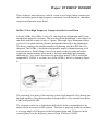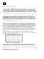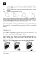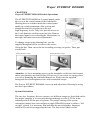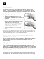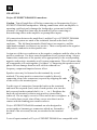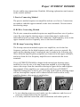
1
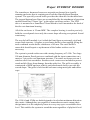
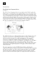
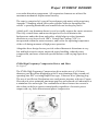
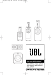
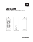
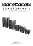
Project EVEREST DD66000
Project EVEREST DD66000
Product Commentaries
and User Guide
Thank you for purchasing Project EVEREST DD66000 loudspeaker system.
Before using the system, please take time to read through this user guide to
understand well on this product and also to use it properly.
User's Guide
Table of Contents
Chapter 1
Preface
Chapter 2
Legacy
Chapter 3
Project EVEREST DD66000
Chapter 4
Unpacking
Chapter 5
Selecting Cable
Chapter 6
Amplifier Recommendations
Chapter 7
Placement and Set-up Considerations
Chapter 8
Switch Operations
Chapter 9
Connections
Chapter 10
Care and Maintenance
Chapter 11
Troubleshooting and Service Guide
Chapter 12
Ownership Register
Chapter 13
Project EVEREST DD66000 Specifications
Project EVEREST DD66000
CHAPTER 1
Preface
JBL wishes to thank you for selecting a Project EVEREST DD66000
loudspeaker system. It represents the sum total of our research and
developmental efforts in sound reproduction over the last half century. We have
labored to create a loudspeaker system with no acoustical or electrical
limitations whatsoever. While the Project Everest DD66000 loudspeaker is
itself a new development, the goal behind it goes right back to the earliest days
of the original James B. Lansing Sound Company.
But it is your listening pleasure that ultimately determines how successful we
are in this endeavor. It is solely in the interest of ensuring a perfect listening
experience that we ask you to faithfully follow the set-up and operation
procedures outlined in the Project EVEREST DD66000 Owner’s Reference.
This manual exists for several purposes.
As your owner's manual, it contains all necessary background information and
detailed instructions for setting up your Project EVEREST DD66000
loudspeaker system, including unpacking the loudspeaker, selecting the correct
location, speaker wire, wiring scheme and amplification, and connecting it up
to its associated electronics. This information will be found in Chapters 4
through 8. In addition, we have included a detailed description of your Project
EVEREST DD66000 loudspeakers (Chapter 3) so that you may become
thoroughly acquainted with its unique design and technological features.
Although physically and materially imposing, the set-up procedure of the
Project EVEREST DD66000 loudspeaker system is relatively simple. We
strongly urge you to read this manual thoroughly before you begin, and consult
it frequently throughout the process. Considerations must be made in placing
the speakers; their stature makes it imperative that you become familiar with
the entire set-up process in advance.
Also, we believe that the historical and technical information included will add
immeasurably to your total enjoyment of the loudspeaker system. As a
loudspeaker, Project EVEREST DD66000 is unparalleled in the field of sound
reproduction. The story and principles behind it are an interesting, informative
and fitting precursor to a lifetime of musical enjoyment.
CHAPTER 2
Legacy - the historical development of the JBL Project loudspeakers
Of those few who seek perfection in sound reproduction, only a handful have
actually achieved it. The price is always high. It is a rare occurrence indeed
when an individual or group is able to triumph over the constraints of economic
and technological reality just once.
At JBL, this has happened eight times. In each case, its engineers were told to
build the speaker system they had always wanted to build. Whatever resources
were required would be made available. Thus began an ongoing investigation
into new frontiers of sound reproduction, beginning mid -century in 1950 and
continuing to the present day.
The products that have resulted fromthis venture are now known as the JBL
Project loudspeakers. Each represents the absolute peak of every technological,
material and engineering innovation available at that time, combined into a
single system. They are Hartsfield, Pragon, Everest DD55000, K2 S9500/7500,
K2 S5500, K2 S9800, and K2 S5800. The newest is EVEREST DD66000.
Although differing in performance details and physical attributes, each of the
Project loudspeakers has shared a common objective: to elevate sound
reproduction to levels defined only by the limitations of existing materials and
technology. And despite a spread of nearly sixty years, all Project loudspeakers
have shared many common features testimony to their foundation on the
technology and manufacturing techniques upon which JBL was built.
Defining the Project Concept
The Hartsfield began a tradition at JBL that continues today. First, engineer a
product as close to perfection as possible. When it reaches that level, that is the
time to make it better.
In 1954, the Hartsfield was significant not in that it represented new technology,
but rather a new level of the all technical manufacturing approach pioneered by
James B. Lansing some twenty years before it. Like its Project series
successors, it was a high efficiency system incorporating compression driver
technology, one combining the qualities of high output, low distortion,
exceptional stereo imaging and fatigue-free listening. Most important, it was
the first consumer-available listening system to do so.
Project EVEREST DD66000
In this respect, Project EVEREST DD66000 is at once the most advanced and
sophisticated loudspeaker in the world today and a speaker whose technology
is deeply rooted in over 60 years of tradition. JBL's president in 1954, Willia m
Thomas, described the Hartsfield as "...the speaker system we have always
wanted to build ... the finest components ever made available to serious
listeners . "
He went on to describe the process behind his creation: “Most people who own
and appreciate fine sound reproduction equipment look forward to the day
when they will be able to assemble a system without limitation in just exactly
the way they think it should be done. Periodically a manufacturer gets this same
feeling ... The science of acoustics has provided us with basic
principles-available to all for achieving precision reproduction. It is only a
matter of incorporating these methods into a system design, and then taking
every bit of trouble necessary to build a system precisely to the design.”
"It isn't easy, but that's the way it is done . "
The Ranger-Paragon, JBL's second Project system, was the first serious
attempt at a reflecting speaker system, and broke ground in the new concept of
stereo imaging. Essentially two independent full-range speaker systems
installed in a handsome curved cabinet nearly 9 feet (2.7 metre) long, the
Paragon's enclosure was treated as an extension of its transducers. In essence,
the system had its own "built-in acoustics." In many respects the Paragon
anticipated loudspeaker developments that would occur years-and even
decades -later. This “built-in acoustics” concept is inherited in the latest Project
EVEREST DD66000.
For nearly 30 years, the Paragon remained the most acoustically viable sound
system for the home. Today, along with the Hartsfield, it is still the most
sought-after speaker in the world.
In 1986, JBL introduced a new Project system that retained the Paragon's
overall sense of musicality while upgrading its character by incorporating three
decades' worth of continuous development in every facet of its design. Its name
reflected the pinnacle of achievement it represented: Project Everest. This was
the original Project EVEREST DD55000.
For the first time, the rest of the sound reproduction chain - and not the
loudspeaker or its transducers - would impose limits on overall system
performance. Like the Paragon and Hartsfield, Project Everest was built
around compression driver technology and addressed a more refined stereo
image than was previously considered technically feasible.
Since Project Everest was introduced, sound recording and playback
technology has undergone a revolution of its own. With the advent of CD,
extremely demanding recorded signals had become the rule rather than the
exception - the average source material used by the typical audio enthusiast had
become superior to the best demonstration material of even just a few years ago.
In overall dynamics and transient response, transducers are once again a
potential weak link in the high-end audio reproduction chain.
It was in this environment that JBL set out to create its fourth and fifth Project
loudspeakers, K2 S9500 and K2 S5500. As with Hartsfield, the puritan
simplicity of a two-way system was considered the most promising design
track. Advances in transducer design and low frequency alignment would make
the construction of a two-way system of unprecedented physical and acoustical
scale possible. Engineers took the core components - the low and high
frequency drivers - and optimized them by redesigning their magnetic
structures, diaphragms and framework for greater linearity, dynamic capability
and transient response.
In the years following the introduction of the K2 S9500 and K2 S5500, sound
reproduction technology underwent another series of revolutionary changes,
with the introduction of DVD-Video, Dolby Digital, DTS, DVD-Audio, and
Super Audio CD (SACD). Frequency responses to 50 kHz and 3-digit dynamic
range and signal-to-noise ratios have now become commonplace. In order to
faithfully reproduce such robust sonic properties, the loudspeaker needed to
undergo drastic improvements to its transducer, network and enclosure
technologies .
The new K2 S9800 employed a 3-way design, incorporating an Ultra High
Frequency (UHF) compression driver and horn to reproduce high frequencies
up to 50 kHz. With the UHF handling the high frequencies, the High Frequency
(HF) transducer could then be upgraded to a new design using a 3 inch
diaphragm for better reproduction of lower frequencies and better blend with
the woofer than the older generations’ 2-inch diaphragm. Both compression
drivers utilized newly developed Beryllium diaphragms to provide the lowest
distortion and flattest frequency response possible.
In order to recreate the extremely high dynamic range provided by today’s
audio sources, a brand new low frequency transducer was developed from
ground up, utilizing an Alnico magnet, 4-inch edge wound Voice Coil, and a 15
inch cone. Extensive computer-aided engineering and design effort made to
develop the optimized port tuning employed in Project K2 S9800 has resulted
in a significant advance in the concept of state-of-the-art acoustic reproduction.
Project EVEREST DD66000
As an outcome of the K2 development, a loudspeaker system with higher
sensitivity and wider dynamic range became reality without power compression
or distortion even at an extremely high drive level.
The development of the Project EVEREST DD66000 loudspeaker system was
started as a celebration of JBL’s 60th Anniversary and as a realization of the
above-mentioned potentials . The solemn personality of the Hartsfield,
exceptional wood-craftsmanship of the Paragon, “built-in acoustics” which
considers the enclosure as an extension of transducers , and the state-of-the-art
transducer technologies that were build up from two generations of the Project
K2 developments are poured into this new challenge to the acoustical and
electrical limitations in the second model of the Project Everest.
Despite its power and sophistication, Project EVEREST DD66000 is a marriage
of tradition and technology. It reflects the design, material, engineering and
manufacturing expertise derived and refined through nearly six decades of
experience that are the exclusive province of one loudspeaker builder: JBL.
CHAPTER 3
The Project EVEREST DD66000 loudspeaker: a triumph in acoustics and
technology
The following sections describe the primary features and components of the
Project EVEREST DD66000 loudspeaker system.
The basic system configuration is what JBL has historically referred to as an
augmented 2-way. In the 1950’s and 1960’s JBL built primarily 2-way systems
with a 12” or 15” woofer crossed over to a large format compression
driver/horn combination. Some of the systems would be “augmented” by a
UHF device, most usually the 075 ring radiator that would operate above 8 kHz.
These systems would have only a single crossover point in the middle of the
audio range in an attempt to minimize any sonic degradation caused by the
dividing network. The DD66000 has a single midrange crossover at 700 Hz
blending one 1501Al woofer to the 476Be compression driver and horn
combination. The 045Be -1 UHF driver is brought in at 20 kHz to cover an
octave and a half of ultrasonic frequencies. A second 1501Al operates in the
bass frequency range from below 30 Hz to around 150 Hz where it is rolled off
at a gradual 6 dB/Octave. The first order slope ensures proper amplitude and
phase summing between the two woofers over their total operating range. Both
woofers operate below 150 Hz but only one of them extends up to the 700 Hz
crossover point. This is done to achieve proper directivity control throughout
the entire woofer operating range while delivering powerful and extended low
frequency performance. Above 700 Hz, the HF compression driver and horn
combination operates unassisted all the way to 20 kHz. (Fig.1)
Figure 1 – On-Axis response of the DD66000 system and that of each of the transducers through its
crossover network. (2.83V @ 1m)
Project EVEREST DD66000
The transducers, horns and crossover networks are housed in a visually
stunning enclosure that is reminiscent of both the Hartsfield and Paragon
systems. The specially curved baffle provides the sidewalls for the main horn.
The top and bottom horn flares are accomplished by the attachment of precision
molded SonoGlass™ horn “lips” to the upper enclosure surface. The UHF
driver is mounted to a SonoGlass™ horn which is itself mounted to the back of
the die cast aluminum housing.
All of the enclosure is 25 mm MDF. The complex bracing is used to precisely
hold the curved panels in exactly the correct shape allowing exceptional fit and
consistency.
The woofer baffle module is a 6-sided shell and form an extremely rigid and
secure final structure. A leather covered outer baffle is then applied giving the
total combined woofer baffle a thickness of 45 mm. The outer baffle is
removable should repair or replacement of the leather surface ever be
necessary.
The system is ported on the rear with a tuning frequency of 34 Hz. Two large
100 mm diameter flared ports are combined with the input connections on a
massive 3-piece die cast aluminum structure. The entire enclosure rests on 4
stainless steel foot assemblies. Stainless steel coasters are included to protect
wood and tile floors from damage from the spike feet. The grille assembly is
constructed of MDF and uses a thick, perforated metal sheet to provide the
curved shape. The grille is held on the enclosure using metal pins and rubber
cups.
The 1501Al and 476Be are both designed to be absolute minimum distortion
drive units. Although they are capable of tremendous acoustic output, their
design intent is to be completely linear in every way up to a reasonable drive
level. This enables the system to sound the same regardless of playback level.
TRANSDUCERS
The 1501AL Low Frequency Driver
See Figure 2
The 1501A L Low Frequency driver is very similar to the 1500A L used in the
S9800 system. It incorporates a new high impedance voice coil to allow a pair
of woofers to be used while still maintaining an 8 ohm system impedance. The
voice coil length has been increased to 30.5 mm (from 20.3 mm) and its milling
width has been reduced slightly. This was done to allow greater clearance from
the outer diameter of the coil to the laminated top plate and to provide a larger
surface area of coil surface for heat dissipation. These coil improvements allow
the 1501A L to handle up to 25% more power than the 1500A L.
Figure 2 – 1501AL section view
The 1500AL LF driver is a 380 mm diameter device with a 100 mm voice coil
completely immersed in a radial field generated by an Alnico 5DG magnet.
Alnico was chosen because of its stable operating point. This material is
insensitive to temperature changes and back EMF from the coil. JBL has
overcome the tendency of Alnico to demagnetize with high drive by utilizing a
massive shorting ring at the base of the motor assembly. The top plate is
constructed of alternating copper-steel laminations. The presence of the copper
rings linearizes the magnetic properties of the gap to all but eliminate eddy
current distortion.
The outer suspension is made of EPDM foamed rubber, which has the
longevity and frequency response characteristics of traditional rubber surrounds,
but with a low density very close to that of foam surrounds. Low loss EPDM
material was chosen so that the transient detail of musical signals could be
preserved. Dual inverted Nomex spiders are employed for the cancellation of
Project EVEREST DD66000
even-order distortion components. All suspension elements are tailored for
maximum mechanical displacement linearity.
The cone is comprised of a special layered paper pulp matrix with proprietary
Aquaplas ™ damping which offers more pistonic behavior throughout the
woofer’s operating bandwidth, and controlled cone breakup beyond it.
A thick wall, cast aluminum frame is used to rigidly support the motor structure.
This fully vented frame and motor design also serves to minimize the
backpressure under the dome and spider, which helps to reduce harmonic
distortion to even lower levels. JBL’s Vented Gap Cooling (VGC) is
incorporated within the motor structure, and lowers the operating temperature
of the coil during moments of high power operation.
Altogether these design factors provide reduced harmonic distortions at very
low and high acoustic output, improved power handling, reduced power
compression, and more consistent spectral balance with varying input drive
level.
476Be High Frequency Compression Driver and Horn
See Figure 3
The 476Be High Frequency Compression driver makes use of a 100 mm
diameter, pure Beryllium diaphragm with 99 mm aluminum Edge-wound coil,
operating into JBL’s existing Rapid Flare type, Coherent Wave phasing plug.
The use of an efficient Neodymium rare-earth motor structure with new Copper
Sleeved pole piece maintains maximum gap flux and reduced coil inductance at
a minimum size and weight. The combination of these features has created a
driver that can deliver superior sound quality regardless of acoustic power
output with very little distortion and power compression.
Figure 3 – 476Be section view
A high purity copper sleeve is used for the pole piece. This greatly
improves the electrical conductivity of the copper sleeve for lower coil
inductance and thus greater high frequency output at 15 kHz and above.
The copper sleeved pole quickly wicks away heat generated by the coil and
contributes in reduction of dynamic power compression. To compensate
for the higher reluctance gap caused by the use of a copper sleeved pole
piece, large magnet area was used in conjunction with special high-grade
and high-temperature grade Neodymium.
The Phasing plug is of JBL’s traditional Rapid Flare, Coherent Wave 4-slot
design. This Coherent Wave design shapes the wave output producing a
truly coincident wave front as the sound enters the horn.
The diaphragm is formed of pure Beryllium foil that is manufactured with
a proprietary, high temperature and pressure forming process. This process
enables the proprietary integrated JBL diamond surround to be formed as
one piece with the dome. Compared to other methods, forming the
diaphragms out of sheets of Beryllium foil yields greater reliability and
resistance against failures due to fatigue. If breakage ever does occur, the
diaphragm does not shatter into pieces or harmful dust. Beryllium has a
stiffness-to-density ratio about 5 times that of Aluminum, Magnesium,
Titanium, and Iron. This enables to maintain pistonic behavior up to
20,000Hz, eliminate diaphragm modal breakup and keep the upper
frequency response very smooth with minimal distortion spikes. Compared
to the 475Nd compression driver use in JBL’s original K2 S9500 system,
this is about a 45% reduction in moving mass. With such a low mass, the
moving assembly is able to respond even quicker to musical transients to
further enhance detail and micro dynamic nuances.
JBL’s diamond pattern surround is utilized to maintain proper control and
tuning of the second diaphragm resonance (the surround resonance mode).
The proper control and placement of this surround resonance is critical for
good high frequency shape, extension, and level.
Project EVEREST DD66000
These features, when taken as a whole, create a new large format compression
driver with the greatest high frequency extension, lowest distortion, smoothest
response and greatest sonic detail.
045Be-1 Ultra-High Frequency Compression Driver and Horn
Like the 045Be, the 045Be -1 uses a 25-mm beryllium diaphragm and 50-mm
neodymium magnetic structure. The pure beryllium diaphragm is less than 0.04
mm thick and has a mass of only 0.1 gram. The single layer aluminum ribbon
voice coil is wound without a former and attached directly to the diaphragm.
The driver employs the smallest annular slit phasing plug that JBL has ever
designed. The 045Be-1 has been redesigned to improve manufacturing yield
and consistency. Small changes have been made to the top plate and some
significant improvements were made to the surround shape and clamping
methodology. As a result, the driver has picked up nearly 5 dB of increased
output above 30 kHz. A section view of the 045Be-1 driver is shown in Figure
4.
Figure 4 – 045Be-1 section view
The extremely low mass of the moving system, high magnetic flux density and
the high rigidity of beryllium produce response that is very smooth from below
8 kHz to beyond 50 kHz.
The response curve has a slight down hill tilt due to the constant directivity
nature of the horn used in this system. The horn is properly scaled to maintain
a coverage angle of 60 degrees in the horizontal plane and 30 degrees in the
vertical plane over the frequency interval from 10 kHz to 50 kHz.
Internal Crossover Network
The circuit topology, combined with the acoustic behavior of the 1501A L and
476Be provides a 24 dB-per-octave transition at 700 Hz. This is the primary
crossover point of the system. Additionally, the 045Be-1 is turned on above 20
kHz to provide extended response to beyond 50 kHz. A second 1501A L woofer
is used from below 30Hz to around 150 Hz at which point it is gently rolled off
at 6 dB-per-octave. The design intent is to use both woofers in the bass
frequencies and slowly transition to a single woofer in the midrange. This
technique allows a primary crossover point between just two drivers and
permits proper control of the directivity pattern of the system while providing
tremendous power and air movement capabilities at the lower frequencies. As
a result, the speed and power of the DD66000 system is unmatched from the
lowest to the highest frequencies.
All of the electrical components are of the highest quality and lowest internal
loss. The inductors used are air core so as to not introduce nonlinear hysteresis
effects. Capacitors are constructed using polypropylene foil, which is known
for having minimal distortion caused by dielectric absorption nonlinearities.
The mid, high and ultra-high frequency networks employ battery bias to
operate the capacitors effectively in a Class A mode. Every attempt is made to
present as smooth a system impedance as possible to the driving amplifier.
This design element is often overlooked in many loudspeaker systems.
Amplifiers work their best when they are given a smooth, level load impedance
in which to deliver current. (Fig.5)
Figure 5 – DD66000 system impedance
The aggregate of these attributes allows the DD66000 system to translate the
electrical signal from source material into an accurate and unencumbered
three-dimensional sound field. The system can do this at any desired listening
level from whisper quiet to big-band loud while at the same time, maintaining
unchanged acoustic characteristics.
Project EVEREST DD66000
CHAPTER 4
Unpacking the Project EVEREST DD66000 System
All components of the Project EVEREST system have been very carefully
packed for maximum protection against damage.
As with any superior audio product, it is advisable to keep the original packing
materials in case it is necessary to transport the Project EVEREST system.
Because of the bulk and weight of this loudspeaker, at least two people are
required to unpack it in the following manner.
Stainless steel round feet are installed onto the bottom of the speaker cabinet.
In order to avoid damages to the floor, we strongly advise to unpack on a well
protected surface such as a thick carpet or cardboard. (Loudspeaker system is
wrapped with non-wovens for protection, but this is omitted in drawings
below.)
I.
Cut the straps, which tie the carton, by scissors or a knife. (Please be
careful that the cut strap springs up and hit your face or hand.)
Slowly lift up the top cover and remove it. If there is not enough room
above the box to pull out the top cover, cut side and top of it by a knife
(drawing II-2) and pull it horizontally (drawing II-3).
II.
I
III.
IV.
V.
II
II-2
II-3
Remove cardboard and packing materials. Please do not forget to
take out accessories from the upper endpads.
Remove upper endpads.
Slide down the loudspeaker system from the bottom board together
with bottom cardboard.
III
IV
V
VI.
VII.
VIII.
Cut tapes at the corners of the bottom cardboard (drawing VI), slide
out the loudspeaker system toward you together with bottom endpads
(drawing VI-2).
Lift the system slightly on the right and left in turn to remove bottom
endpads.
Remove the protective non-wovens.
VI
VI-2
VII
VIII
Products are shipped with round-tipped spikes on the bottom of the cabinet. If
you would like to use pin-point spikes, please refer to figure 6 on page 12, and
remove round-tipped spikes and replace them with pin-point spikes. In case,
it is hard to loosen, please use 18mm size spanner/wrench.
Four metal coasters are also provided. These are to be placed between
the foot and the floor should further protection of the floor coverings be
required.
Grille Removal
The EVEREST DD66000 is shipped with its grille on the system. You
can remove the grille in the following procedures.
Step 1: Hold the lower parts of the grille with both hands and pull it up.
Step 2: Pull the grille toward you in order to take the grille out of the
pins from the cabinet.
Step 3: Pull the grille down and remove the grille from the cabinet.
Repeat the above procedures in a reverse order in order to install the grille back
to the cabinet.
Project EVEREST DD66000
CHAPTER 5
Selecting Cable
Speaker wire and interconnecting cables are an important component in any
audio system. With a system such as the Project EVEREST, they assume a
new level of criticality.
The Project EVEREST loudspeakers are internally wired with proprietary high
quality copper cable s, specially designed for JBL. The same care that was given
to the selection of internal system wiring should be afforded to the selection
and application of the cables that will connect Project EVEREST loudspeakers
to other system components.
It is advisable to use high quality wire and to select the highest grade wire
available from the manufacturer. Many manufacturers produce audiophile
cables worth considering for Project EVEREST. As with all electronics and
associated comp onents, however, every manufacturer offers products of
varying quality to suit a range of budgets and applications.
We recommend using an audiophile quality speaker wire of not less than 16
gauge for connections up to 5 meters (15 feet) as a minimum requirement.
Project EVEREST specialist dealers have the experience and knowledge to
recommend suitable speaker wire to best complement a particular system.
For maximum signal purity, it is advisable to locate the amplifier(s) as close as
possible to the loudspeakers, even if this means that a longer distance will be
needed between the amplifier(s) and preamplifier.
Both the left and right speaker/amplifier connections should be the same length.
If the distance between one speaker and the amplifier(s) is greater than the
other speaker and amplifier(s), use the longer length for both connections.
For bi-wire connections, the same type of wires may be used for both low
frequency and high frequency sections to reduce wire effects (resistance,
inductance, etc.) and to avoid intermodulation of low and high frequencies in
the wires. Specialized wires for low frequency and high frequency sections may
yield excellent results. Whatever wires are used, be sure that the low frequency
wires are as short as possible and the left and right wires for each section are
the same length.
To secure firm connection, we recommend Y or U type plugs.
CHAPTER 6
Amplifier Recommendations
No single type of amplifier is specified for use with the Project EVEREST
DD66000 system. The speakers are highly efficient and will operate adequately
with an amplifier or receiver of 70-100 watts.
However, the transient response and audio definition of a high-end system such
as Project Everest DD66000 will pick up all inefficiencies and distortion in an
amplifier system. For full-range operation, the Project Everest DD66000
system should not be used with an amplifier/receiver of less than 100 watts.
Amplifiers/receivers of 100-500 watts will ensure optimum system
performance.
There is no effective limit to the power handling capabilities of the Project
EVEREST DD66000 loudspeakers when driven by consumer audio amplifiers.
No damage will occur when used with high powered components. Source
impedance is an important criterion in selecting an appropriate unit; the
selected amplifier(s) should have a very high current capacity and must be
capable of driving a low-impedance load.
For bi-wiring or bi-amplification applications, four identical amplifiers or two
dual-channel units may be used, although specialized low frequency and high
frequency amplifiers offer clear advantages. (If four amplifier channels are
used, the high frequency amplifier may be up to 6 dB less powerful than the
low frequency amplifier. Due to the power versus frequency distribution of the
music, the low frequency section requires approximately four times the power
of the high frequency section.).
Project EVEREST DD66000 specialist dealers can recommend amplification to
best suit individual needs. In all cases, the left and right amp lifiers for each
section must be identical. Make sure that the input sensitivity of the two
amplifiers is equal or that input level controls are provided to maintain the
proper low to mid/high balance. If two identical stereo amplifiers are chosen,
each amplifier may be located near a loudspeaker and drive low frequency and
high frequency sections through short wire runs.
The addition of a crossover network should be connected directly to the low
and high frequency amplifiers driving this system, and is required if the system
is to be biamplified.
Project EVEREST DD66000
CHAPTER 7
Placement and Set-up Considerations
The Project EVEREST DD66000 loudspeaker system is designed to be less
affected by room acoustics than conventional imaging systems. However, it is
very sensitive to overall symmetry, proximity to walls, ceilings and corners.
Ideally, any listening room should contain a combination of live surfaces (e.g.,
walls and windows) and absorbent surfaces (e.g., drapes, carpets, upholstery).
If the distance between floor to ceiling is low, it is preferable that one surface
has an absorbent covering. With Project EVEREST DD66000, it is most
important to be able to accommodate the optimum listening area that is defined
by the 100° horizontal/60° vertical coverage pattern of the horn.
In order to obtain the best stereo effect, the speakers should be placed at the
same distance from the listening position.
• The distances to the right and left speakers are determined by the
relationship between the
distance from the listening
position to the speakers and the
angles of the speakers (refer to
the figure on the right). The
imaging qualities enable the
speakers to be placed relatively
far apart from each other, but
this weakens center imaging
such as vocal. By increasing
the inward angle of the
speakers toward the listener will improve the center imaging.
• The listener should be centered in
front of the speakers and furniture
should be of an appropriate height so
that when the listener is sitting, the ear
level is on a vertical plane with the
high-frequency horn (approximately
90 cm/ 35.5 in) as illustrated on the right.
• The surrounding environment for the speakers affect bass sound quality.
Placing the speakers close to wall behind them or side walls bring about
abundance of bass, but too close distance will result in dull bass. On the
other hand, too much distance will reduce the mass of bass but result is in
fast and sharp bass. The low frequency alignment feature enables placing the
speakers near or even in a corner without producing an over-abundance of
bass. This corner placement ability allows optimum performance even in
small rooms . Find the most suitable point by using various source materials.
The Project EVEREST DD66000 requires right or left speaker designation,
depending on installed locations. Once speaker locations are decide, please
refer to System Orientation in Chapter 8 Control Panel and set it up.
CAUTION: Project EVEREST DD66000 is a massive system comprised of
materials chosen for their density, with its weight concentrated in a relatively
narrow area. Verify the integrity of the floor surface before placing and setting
up the speakers. See Floor Requirements. Remember that these speakers
weigh close to 140 kg (308 lbs) each and cannot be easily moved once they are
installed.
Floor Requirements
The floor in the location selected for setting up the Project EVEREST DD66000
speakers must be capable of supporting a load of 140 kg (308 lbs). Because of
the coupling effect of the stainless steel feet, a flat, hard surface such as wood
or linoleum is preferable. However, the design of the loudspeaker's coupling
system, along with the speaker's extreme weight, should result in excellent
performance on any surface, even on carpets.
To prevent indentations on wood or linoleum floors caused by the weight of the
loudspeaker, always utilize the enclosed coasters. Do not set up the Project
EVEREST DD66000 system directly on a ceramic tile floor; the concentrated
weight might cause the tiles to crack.
Project EVEREST DD66000
CHAPTER 8
Project EVEREST DD66000 Switch Operations
The EVEREST DD66000 has 2 control panels under
the cover at the center bottom of the front baffle.
Shorting bars or switches inside the control panel
enable to switch orientation of the system and
biamplifier and also to adjust woofer and
high-frequency levels. They also provide access to
the 9-volt batteries used for capacitor bias. Remove
the control panel cover referring the illustrations on
the right, and make necessary adjustments.
To change setups using shorting bars, use the
supplied hexagonal driver to remove the screws
fixing the bar. Then, move the bar according to setup you prefer. Then, put
screws back.
Attention: As loose mounting screws on the terminals could cause bad contact,
make sure that they are firmly affixed. However, if you screw too strong, there
is a risk of damaging the terminals themselves. Please use the supplied
hexagonal driver and tighten screws with reasonable torque.
The Project EVEREST DD66000 can set up and adjust the following by using
the above procedures.
System Orientation
The two low frequency drivers operate over different ranges as described earlier.
For proper imaging, it is necessary that the midrange woofer (LF2) be in the
inboard position for the pair of systems. The proper setting of the system
orientation jumper bars can configure a single DD66000 system as either a “left
or right” system. It is necessary that both bars be moved together. Improper
sound will result from staggering the bars. The bars select which woofer
receives the low and which woofer receives the
midrange signals. One system should be set to “left”
and be positioned as the left speaker system. The other
system should be set to “right” and be positioned as
the right speaker.
HF Drive / LF Drive
This allows to switch normal drive using a set of
amplifiers and bi-amp drive using 2 sets of amplifiers.
Move the shorting bar only in case of bi-amp driving.
Selection of the Bi-Amp position for the shorting bars bypasses the crossover
function for the full range woofer and the high frequency driver. The low
frequency woofer and the ultra-high frequency drivers are unchanged. Use of
this feature requires the addition of an external dividing network to provide the
700 Hz primary crossover point for the system. The built-in attenuation and
equalization for the 476Be remains in place. The high frequency level trim
remains operational, as does battery bias for both the low and high frequency
sections. Normally all 3 sets of bars (2-LF and 1-HF) would be moved
together. It is possible to operate the system with just the low frequency
system or the high frequency system set to Bi-Amp. Under this circumstance
it would be necessary to use a combination of external dividing network along
with the internal network. However, this would require some very special
needs and is not generally recommended. Figure 12 shows the low frequency
and high frequency voltage drive functions necessary to properly Bi-Amplify a
DD66000 system using an external dividing network and two amplifiers
channels. Neither the low pass nor high pass drive is a standard Butterworth
alignment or, for that matter, any standard alignment. The provided drive
curves were derived using the internal passive network and resulting acoustic
low pass and high pass shapes. Duplicating these shapes will result in the
same frequency response and directivity pattern as a passive DD66000. The
low pass is made up of two cascaded second order sections and the high pass is
a single high pass section. The values within a high quality analog dividing
network can usually be modified to achieve these results. Recent digital
crossover units will have no problem duplicating these curves.
Figure 12
Project EVEREST DD66000
HF Level
This switch adjusts the attenuation applied to the 476Be (high frequency or HF
unit) by approximately 0.5 dB over the range of 1,000 Hz to about 8,000 Hz.
The action is accomplished by trimming the main attenuation resistors.
Mid-range sound becomes calm by reducing level and brighter by increasing
level. No addit ional parts are inserted in the signal path and there is no sonic
deterioration by position or adjustment functions.
LF Level
There is a level trim available for each of the two woofers (LF1 and LF2).
Moving a bar from Low to High will increase the drive level to a portion of the
frequency spectrum over which each woofer operates. LF1 refers to the low
range woofer (up to 150 Hz) and will affect the output level in the range of
60Hz – 150Hz by about 0.5 dB. LF2 refers to the main woofer and will affect
the output level in the range of 150 Hz to 700 Hz. The purpose of these
adjustments is to allow fine-tuning of the mid-bass and midrange response of
the system to better integrate with varying room characteristics.
Normally, the control bars of LF1/LF2 are moved together to get the maximum
effect (LF1 & LF2 = High or LF1 & LF 2 = Low). Depending on room
environment, you may get a good balance by moving of them. In case speaker
systems are placed close to corners of the room and the distance between 2
systems are great and you notice bass boost by reflections from walls , try to
increase the LF2 level and decrease LF2 level (LF1 = Low, LF2 = High). These
adjustments will not cause loss of series element from adjustments they are
done by change values of damp ing resisters which are in parallel.
Change from LF1 level trim
Change from LF2 level trim
Battery Installation
The network of this system utilizes the proprietary JBL “charge-couple
method” to activate capacitors by applying DC bias using battery and this
eliminates unwanted distortions. Please refer to procedures below and install
the supplied batteries on the battery holders.
Battery Installation Procedures:
1. Remove the control panel cover at the
bottom of the front baffle. (refer to figures in
Chapter 8)
2. Remove the package film from batteries and
3.
put these batteries into the battery holders
inside the control panel on the left.
Connector is snap type and has polarities.
Push up battery after making sure that
polarity orientation is correct.
Put the control panel cover back on the
baffle.
Bias is applied to capacitors which are insulation components and there is no
current consumption in batteries. Thus, battery life is the same as battery life
with natural discharge (about 2 years in alkaline batteries).
In order to maintain the bias effect, we recommend to replace batteries
regularly in every year or two.
Only the same type of battery (006P rectangular 9V alkaline battery) must be
used. This battery can be easily found at electric appliance stores and
convenient stores.
* The supplied batteries are for testing the bias function, and they should be
replaced with new batteries soon.
* Bias is applied to reduce distortion from components. In the event of flat
battery, there is no effect on the network circuitry, and there is no symptom as
no sound or intermittent sound from the system. However, you will notice the
level of distortion reduction effect of the bias network circuitry after new
batteries are installed.
The batteries provide a voltage bias to each of the capacitor positions in the
various networks. The biasing of the capacitors is done through a large value
Project EVEREST DD66000
resistor (2.2 MO) and thus, draws no appreciable current. The expiration date
printed on the battery generally coincides with the need to replace the batteries.
Each capacitor position is actually made up of two capacitors connected in
series. The battery voltage is applied to the center connection of the two
capacitors. This produces a voltage potential between the two plates within the
capacitor. When the two parts are taken as a whole, there is no DC voltage that
appears across them, but individually they are each biased. The sonic result of
the biasing yields an increase in detail, increased smoothness and considerably
more natural decay of sounds within the music.
CHAPTER 9
Project EVEREST DD66000 Connections
Caution: Turn all amplifiers off before connecting or disconnecting Project
EVEREST DD66000 loudspeakers. Making connections while an amplifier is
operating could seriously damage the loudspeaker system and void the
warranty. All amplifiers must also be turned off before connecting or
disconnecting cables at the amplifier or preamplifier inputs.
All connections between the amplifier(s) and the Project EVEREST DD66000
loudspeaker system are made at the terminals located on the back of the
enclosure. The left-hand terminals (black letters) are negative, and the
right-hand terminals (red letters) are positive. These correspond to the negative
and positive conductors in the speaker wire.
Assign one of the two conductors as the negative conductor and the other as the
positive conductor. Use these same designations for all system wiring. Always
connect the conductors of the speaker wire appropriately to the corresponding
negative and positive terminals on all system components. This will ensure that
all components will work together (“in phase”). Connecting the speakers out of
phase will not damage them but will result in reduced low
frequency output and impaired stereo effect.
Speaker wires may be fastened to the terminals by several
methods. The most positive connection is made by directly
connecting clean, bare connectors (exposed by stripping the ends
of the wire) to the terminal posts.
For this type of connection, loosen the knobs on the terminals
and insert the exposed (bare) ends of each speaker wire into the
hole exposed on the terminal shaft (+ to +, - to -). Retighten the
knob on each terminal so that a snug positive connection is
achieved. Do not apply excessive force and do not overtighten.
To avoid a short circuit, trim off any excess wire that is not in
contact with the binding post contact surfaces.
Project EVEREST DD66000 terminals are also designed to
accept spade or banana-type connectors which are fastened to
the ends of the wires and, in turn, are attached to the terminal
posts.
2 sets of input terminals of Project EVEREST DD66000 are compatible with
Project EVEREST DD66000
bi-wire and bi-amp connections. Read the following explanations and connect
in the suitable method.
I. Passive Connecting Method
The passive method requires one amplifier and one set of wires. Connections
are made to either the upper terminals or the lower terminals . Do not remove
the shorting straps.
II. Bi-Wire Connecting Method
The bi-wire connection method requires one amplifier and two sets of speaker
wires. By removing the shorting straps, connections may be made to the
individual network sections using four connectors, high frequency wires to the
upper terminals and low frequency wires to the lower terminals.
III. Bi-Amp Connecting Method
The bi-amp connection method requires two amplifiers, one for the low
frequency and one for the high frequency unit, and a crossover network. By
removing the shorting straps, connections may be made in the following way.
Wires from the high frequency amplifier are connected to the upper terminals,
and wires from the low frequency amplifiers are connected to the lower
terminals.
Project EVEREST DD66000 is shipped with twisted pair shorting straps
installed. In case bi-wire or bi-amp connection method is to be employed,
remove the straps from the terminals referring to figures below and retighten
the terminals. If the amplifiers are connected to the Project EVEREST
DD66000 loudspeakers in the bi-wire or bi-amp mode with the shorting straps
still on, the amplifier outputs will be shorted which could result in costly
amplifier damage when power is switched on.
• In case shorting straps are used, make sure the conductors and sleeves of
straps are firmly fastened by the terminals.
• For safety and firm connection, cable termination with either spade or
banana-type connector is recommended.
As mentioned earlier, the Project EVEREST DD66000 loudspeakers may be
connected to the amplifier(s) by one of three methods: passive, bi-wire and
bi-amp. Each method, described above, has its own advantages, and the Project
EVEREST DD66000 loudspeaker system will deliver superb performance with
all methods.
Final Checklist:
• Connect and plug in all other system electronics.
• Check all connections. In case of bi-amping or bi-wiring, make sure both
shorting straps are removed.
• Make sure the system orientation and HF/LF drive switching in the control
panel are correctly set.
The system is now ready for use. The Project EVEREST DD66000 loudspeaker
system is fully functional as soon as it is set up. There may be subtle tonal
changes in bass output over the first week to 10 days of operation. These are
caused as the movement of the low frequency drivers becomes more fluid and
the parts settle in. This process is completely normal and natural with
transducers of this caliber. Even during this initial period, there is no restriction
on the amount of amplification that may be applied.
Project EVEREST DD66000
CHAPTER 10
Project EVEREST DD66000 Care and Maintenance
The Project EVEREST DD66000 loudspeaker system requires no maintenance
other than an occasional dusting with a soft, dry, lint-free cotton cloth. The
horns may also be wiped with a soft cloth. Treat the lacquered surface very
carefully to avoid scratching the finish. To remove fingerprints and smudges,
apply a small amount of diluted ammonia -free or alcohol-free neutral detergent
to the cloth and gently clean the surface.
Never use any abrasive cleaners or chemicals to clean the enclosure. If the
enclosure becomes perceptibly scratched or otherwise damaged, consult a
qualified furniture repair shop.
All wiring connections should be inspected and cleaned or remade periodically.
The frequency of maintenance depends on the metals involved in the
connections, atmospheric conditions, and other factors. Consult the Project
EVEREST DD66000 specialist dealer for specific recommendations.
CHAPTER 11
Troubleshooting and Service Guide
Project EVEREST DD66000 loudspeakers are designed to provide years of
trouble-free service. No maintenance is required.
If a problem occurs, make sure that all connections are properly made and clean.
If a problem exists in one loudspeaker, reverse the speaker wires to the left and
right system. If the problem remains in the same speaker, then the fault is in the
loudspeaker. In this event, consult the Project EVEREST DD66000 specialist
dealer for assistance. If the problem appears in the opposite speaker, the cause
is in another component or cable.
Project EVEREST DD66000
CHAPTER 12
The Project EVEREST DD66000 Register
In purchasing a Project EVEREST DD66000 loudspeaker system, you have
joined a privileged group of music lovers who have sought, and finally found, a
system that will reproduce sound to a level of perfection of which no other
system in the world is capable.
JBL has established the Project EVEREST DD66000 Register so that we can
provide aftersales services and maintain an ongoing dialog with all Project
EVEREST DD66000 system owners. Through periodic letters and mailings, we
will be able to communicate information of interest to Project EVEREST
DD66000 owners, including news of technological advancements, new
products, and special promo tions. We look forward to sharing these items with
those who have chosen to invest in a Project EVEREST DD66000 loudspeaker
system.
CHAPTER 13
The Project EVEREST DD66000 System Specifications
Low Frequency Driver :
380mm (15”) Pulp-Cone Woofer (1500AL) x 2
High Frequency Driver :
100mm (4”) Beryllium Compression Driver (435Be)
Ultra-High Frequency Driver :
25mm (1”) Beryllium Compression Driver (045Be)
Power Handling (RMS) :
500W
Frequency Response (-6dB) :
45Hz – 50kHz
Low Frequency Extension (-10dB) :
32Hz
Nominal Impedance :
Sensitivity (2.83V@1m) :
8 ohms nominal
5.5 ohms @ 85Hz
3.5 ohms @ 40kHz
96dB
Horn Directivity (horizontal x vertical) :
High Frequency :
Ultra-High Frequency :
100º x 60º
60º x 30º
Crossover Frequency :
150Hz (LLF LPF -6dB/oct)
700Hz (LF LPF -24dB/oct)
20kHz (UHF HPF -24dB/oct)
Control Function :
HF Level Control (-0.5dB / 0dB / +0.5dB)
LF Level Control (Low / High)
LF / HF Drive Mode Switch (Normal / Bi-Amp)
System Orientation Switch (Left / Right)
Finish :
Santos Rosewood (Black Leather Baffle / Gray Grille)
Cherry (Black Leather Baffle / Gray Grille)
Ebony (Black Leather Baffle / Gray Grille)
- Made-to-order
Maple (Cashmere Leather Baffle / Light Gray Grille)
- Made-to-order
Dimensions :
965mm (w) x 1,109mm (h) x 469mm (d)
(incl. feet , not spike, refer to figure16)
Weight :
137kg without grille
142kg with grille
Package Weight :
174kg
Project EVEREST DD66000
JBL and Harman International
JBL is part of the Harman International audio companies, a group with a
common purpose: combining technology with a love of music to manufacture
audio products that provide new levels of satisfaction, performance and value.
To promote diversity and creativity, JBL operates independently in research
and development. When it comes to translating the results of these efforts into
actual consumer and professional products, JBL draws on the full combined
strength of the Harman companies, which includes one of the world's most
advanced manufacturing facilities. The result of this teamwork is that JBL's
renowned excellence in engineering is successfully carried through to each
individual product, regardless of its application or price range.
As new audio concepts and technologies are pioneered, the partnership of JBL
and Harman International guarantees that consumer and professional audio
users everywhere will be able to enjoy their full range of benefits.
JBL continually engages in research related to product development and
improvement. Because of this, new materials, production methods and design
refinements will be introduced into existing products without notice. For this
reason, any current JBL product may differ in some respect from its published
description, but will always equal or exceed the original design specifications
unless otherwise stated.
©Copyright 2006 JBL Incorporated
JBL Incorporated
8500 Balboa Boulevard
Northridge, CA 91329
USA
JBL is a registered trademark of JBL, Inc.
Monster Cable is a registered trademark of Monster Cable Products, Inc.
Aquaplas and SonoGlass are registered trade marks of JBL, Inc.