1
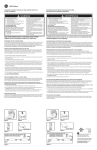
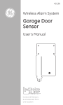
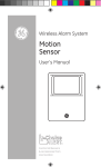
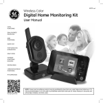
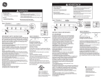
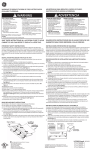
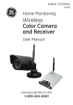
MOTION-ACTIVATED
LED Security Light
User Manual
www.jascoproducts.com
1-800-654-8483
2
Thank you for purchasing the GE LED Security Light with Motion
Activation control. This economical, energy efficient LED light has been designed to allow easy installation, flexible mounting options and
provide exceptional light output with minimum power consumption.
Please read all the Instructions carefully. Keep them for future reference.
PARTS LIST
Before installing please ensure all the following items are
included in the package:
LED Security light with
two light housings
and motion sensor
3 Wire Connectors
TOOLS NEEDED
Phillips head screwdriver #2
Mounting plate
and screws
Mounting Bolt
Gasket
GE Badge
3
Questions? Problems? Missing Parts?
If you have any questions regarding the installation or operation of the
product, Before returning to Retailer, please contact Technical Support at
1-800-654-8483,option 4.
WARNING: Turn power off at circuit breaker or fuse box. Do Not rely
on a wall switch alone to turn off power.
Consult a local licensed electrician or electrical contractor if you are not
sure about the installation. Always install wiring connections in accordance with local code, ordinances and National Electric Code.
WARNING: The LED light output is strong enough to injure human eyes.
Do not stare directly at the LEDs for more than a few seconds.
4
INSTALLATION
Select an existing light fixture, either wall or eave mount for replacement.
Note: The fixture must be connected to 120v, 60Hz power source.
MOUNTING PREPARATION FOR THE LED LIGHT FIXTURE
Note: For maximum flexibility, the LED Security Light can be mounted on a
wall (vertical) or under the eave (horizontal).
Eave Mount
Wall Mount
Lock Nut
Adjustment Knob
LED Housing
Cover
Housing
Mounting
Plate
Motion
Sensor
Dusk/Dawn
Adjustment
Time Adjustment
for Lights
5
Locate the adjustment knob and lock nut on the LED fixture. Loosen both and
position LED light housings into the approximate position prior to mounting. For wall mount, the LED light housings should be positioned above the
motion sensor. For under eave mount, position cover housing horizontally so
that LED light housings are facing outward, away from the wall and motion
sensor is positioned in front of LED light housings.
Fine tune adjustment can be completed after LED light fixture is mounted to
junction box.
WIRE CONNECTION
WARNING: Turn power off at circuit breaker or fuse box. Do Not rely
on a wall switch alone to turn off power.
1. Remove the existing light fixture and disconnect house wires (black, white
and ground).
2. Install mounting plate to junction box as shown using two mounting
screws (included). Install screws until snug so that mounting plate does not
move. Do not over tighten screws. See Fig. A.
3. Position gasket over junction box. Route black, white and ground house
wires through one of the large openings of the gasket. See Fig. B.
Fig. A
Fig. B
6
4. Locate black, white and ground wires coming from LED light fixture. Strip
wires 3/8” (9.5mm) if not previously stripped. Hold BLACK house wire and
BLACK fixture wire together with ends even. Align any frayed strands or conductors. Push wires into wire nut and screw ClockWise until two twists are
visible in the wires. Repeat above procedure for both the WHITE house wire
and the WHITE fixture wire. Repeat above procedure for both the GREEN or
BARE COPPER house wire and the BARE COPPER fixture wire.
Gasket
Mounting Plate
Black to
Black
White to
White
!
House ground
wire to copper
ground wire from
fixture
5. Insert mounting bolt through center
of cover housing as shown. Align
mounting bolt thru the small center hole
of gasket to hold gasket in place.
Position cover housing and gasket over
the junction box. Align center bolt with
center hole of mounting plate. Using
Phillips screwdriver, screw mounting bolt
into mounting plate until LED light
fixture is snug; do not over-tighten.
6. Cover mounting bolt by inserting GE badge into hole;
align badge with mounting slots. Press in until snug.
7. If a location junction box was not used, caulk edge of
cover housing surface with silicone weather resistant
sealant (not included).
!
!
7
ADJUSTING LIGHT HOUSINGS
Adjustment
Knob
1. Slightly loosen adjustment knob and lock nut for
one housing at a time. Gently position LED housing
to final desired position. Tighten adjustment knob
and lock nut. If necessary, follow same adjusting for
the other Light Housing.
2. Turn on power at circuit breaker or fuse box. Turn on light switch (if present). Check LED light output to ensure proper coverage.
TEST MODE, INITIAL SET-UP
Note: After power is turned on, the motion sensor requires approximately
one minute to ‘warm-up’ before it will detect motion levels.
Time
Dark
MAX
MAX
TEST
The LED light fixture is pre-set to the ‘TEST’ mode
from the factory to help you position the motion sensor so it can detect motion in the desired
area. In ‘TEST’ mode, the LED lights will turn on for
approximately 5 seconds each time motion is detected (including during daylight). After completing the test set-up, you can adjust the time the
lights remain on from 1 to 10 minutes (variable).
While in ‘TEST’ mode the lights will turn on during
daylight.
OPTIMIZED LIGHT OUTPUT
Provides a variety of lighting applications. Simply adjust the angle of the lights.
Focused spot with surrounding flood for
entrances, driveway or cars, gate access, etc.
Broad spot with expanded flood
for yards, large areas, decks, etc.
Focused flood for fence line,
shed or remote building,
detached garage, side of
house, boat, trailer, etc.
8
MOTION SENSOR POSITION SET-UP
Note: The motion detection range has been set to a maximum sensitivity, up
to 60ft. This is the optimum, reliable distance. At longer distances, there is
a greater tendency for ‘false activations’. Maximum sensitivity distance will
vary based on outside conditions (temperature, weather), mounting location
and detection angle.
1. Ensure power is turned on to the
LED Light fixture.
2. Loosen the adjustment knob and lock nut for the
motion detection sensor and position it
so points outward toward the approximate middle
of the area to be detected.
Lock
nut
3. Angle the Motion sensor slightly downward (approximately 10-15°). This will create a maximum
detection area with the most accuracy, from 6ft to 60ft.
Too Far
To Close
Adjustment
Knob
Best Option
Avoid pointing sensor too far downward as this will reduce detection coverage and overall distance. If the sensor is pointed too high, it may not detect
movement closer to the fixture. It may be necessary to make minor adjustments until you have the sensor set to the optimum position.
4. Position the sensor so any areas to the far left or far right are covered.
Distance outward from the sensor is fixed, so no adjustments are necessary.
The detection pattern is similar to a half circle, however it will detect farther
ahead than on each side.
9
Important Note:
(1) Do not point motion sensor toward bright lights or reflective surfaces
as this will affect accuracy of the motion sensor.
(2) Avoid areas with heavy traffic or pet areas as this may trigger lights
consistently.
(3) Avoid pointing sensor directly towards severe temperature surfaces
such as heating vents, air conditioners, driveway or asphalt surfaces,
large light-colored objects that reflect heat, or other light sources. These
heat sources can generate ‘false activations’ and reduce motion sensor
distance.
5. Ensure the ‘Time’ knob is set to ‘TEST’ (rotate
Dark
Time
counter-clockwise to left). The Dark knob is set to
the minimum position (rotate counter-clockwise
TEST
to left). In this ‘TEST’ mode, the lights will turn on
for 5 seconds after motion is detected and then
turn off. In the ‘TEST’ mode, the lights will turn
MAX
MAX
on during daylight.
6. To test motion activation coverage, walk
through detection area noting your position when the lights turn on. To
increase the coverage area, raise the motion sensor up slightly. To reduce
the coverage area, position the sensor downward slightly. Once optimum
coverage set, tighten lock nut and adjustment knob until snug. Do not overtighten.
7. Once you have completed the test set-up, adjust the ‘Time’ setting from
‘Test’ position from 1 to 10 minutes as desired. When out of ‘TEST’ mode, the
LEDs lights will not turn on during daylight hours when motion is detected.
10
DUSK/DAWN LIGHT LEVEL ACTIVATION SETTING
Time
The LED light fixture has an adjustable light level activation setting
labeled ‘Dark’. This adjustment allows you to determineTEST
when the
LED lights will turn on based upon the darkness level outside. In
some situations, depending upon on where the fixture is located,
you may wish to have the LED lights turn on sooner (example-the
LED light fixture is positioned in a shaded area). Or you may wish
MAX
to have the LED lights turn on when it is darker outside.(example the LED light fixture is located in an area that receives direct
afternoon sunlight).
Time
Dark
MAX
Dark
1. To set lights to turn on under darker conditions, rotate
DARK
TEST
knob to the right (clockwise) to ‘Max’ position.
2. To set lights to turn on under lighter conditions turn rotate
knob to the left (counter-clockwise) to ‘Min’ position. TEST
3. It may be necessary to make minor adjustments until
satisfied with activation levels.
MAX
MAX
Time
Dark
MAX
MAX
11
LED LIGHT-ON TIME SETTING
Dark
Dark
Time
Time
The LED light fixture has an adjustable time setting
that determines the length of time the LED lights will
TEST
TEST
remain on after motion is detected. You can adjust
the light-on time from 1 minute to 10 minutes.
Adjust the ‘Time’ setting from ‘Test’ position from 1
to10 minutes as desired. Note: In the ‘TEST’ setting,
MAX
MAX
MAX
MAX
the lights will turn on for 5 seconds after motion is
approx. 1 mm approx. 10 mm
detected and then turn off, and will turn on during
daylight.
HOW DOES MOTION DETECTION WORK?
Motion sensors are actually heat sensors. Motion Sensors detect motion by
monitoring changes in heat within the detection area. As a person enters the
detection area, the sensor compares the outside temperature with the body
temperature of the person within the detection area. As the person moves
within the detection area, the heat measurements change. Motion Sensors
determine these changes to be ‘movement’. All motion sensors are more
sensitive to movement across the detection area, and less sensitive to
movement toward the sensor. The Motion Sensor on the GE LED Security
Light is designed to detect motion up to 180°, and outward from the fixture
from 6ft up to 60ft.
Less Sensitive
More Sensitive
FCC Statement
This device complies with Part 15 of
the FCC rules. Operation is subject to
the following two conditions: (1) this
device may not cause harmful interference, and (2) this device must accept
any interference received, including
interference that may cause undesired
operation.
FCC Note: The manufacturer is not
responsible for any radio or TV
interference caused by unauthorized
modifications to the equipment. Such
modifications could void the user’s
authority to operate the equipment.
WARNING
Risk of electric shock
- Turn power off before servicing—see
instructions.
- Properly ground fixture.
- Ensure that no bare wires are exposed
outside the electrical connections.
Risk of injury
- LED light output is strong enough to
injure human eyes. Precautions must
be be taken to prevent looking directly
at the LEDs with unaided eyes for more
than a few seconds.
- Some metal parts in the fixture may
have sharp edges. To prevent cuts and
scrapes, wear gloves when handling
the parts.
- Account for small parts and destroy
packing material, as these may be
hazardous to children.
Risk of fire
- Minimum 90º C supply conductors
No serviceable parts
Non-replaceable LEDs
NOTE: This equipment has been tested
and found to comply with the limits for
a Class B digital device, pursuant to
Part 15 of the FCC Rules. These limits
are designed to provide reasonable
protection against harmful interference in a residential installation. This equipment generates, uses and can
radiate radio frequency energy and, if not installed and used in accordance
with the instructions may cause harmful interference to radio communications. However, there is no guarantee that interference will not occur in a
particular installation. If this equipment does cause harmful interference to
radio or television reception, which can be determined by turning the equipment off and on, the user is encouraged to try to correct the interference by
one or more of the following measures:
• Reorient or relocate the receiving antenna.
• Increase the separation between the equipment and receiver.
• Connect the equipment into an outlet on a circuit different from that to
which the receiver is connected
• Consult the dealer or an experienced radio/TV technician for help
GE is a trademark of General Electric Company and is used under license to Jasco Products Company LLC,
10 E. Memorial Road, Oklahoma City, OK 73114. www.jascoproducts.com
45254 rev. 5/23/11