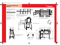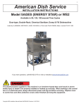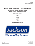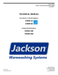
1
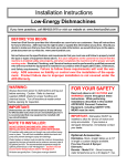
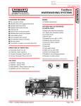
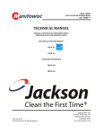
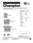
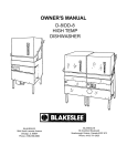
TS-66 Traditional
Series
Standard Features
• 252 racks per hour hi-temp sanitizing
rinse.
• 0.74 gallons per rack hi-temp
sanitizing rinse.
• Incoming water pressure regulator
• Standard 18” clearance.
• Totally electro-mechanical; no solid
state controls utilized.
• Stainless steel frame, legs, adjustable
bullet feet, and front appearance panel
are all standard.
• Standard 8” vent cowls/splash
shields on both wash and rinse ends
of the machine.
• Heavy gauge construction for extra
ruggedness and durability.
• Fully automatic including auto-fill.
• Completely self-draining stainless
steel wash pump.
Power/Connections
Approximate Total Load
208V / 60HZ / 3PH
208V / 60HZ / 1PH
230V / 60HZ / 3PH
230V / 60HZ / 1PH
460V / 60HZ / 3PH
AMPS
51.8
88.3
47.8
81.5
23.9
Booster Heater Options
External 40°F Min. Rise
208V / 60HZ / 3PH
230V / 60HZ / 3PH
460V / 60HZ / 3PH
KW
24
24
24
AMPS
66.6
60.2
30.1
External 70°F Min. Rise
208V / 60HZ / 3 PH
230V / 60HZ / 3PH
460V / 60HZ / 3PH
KW
36
36
36
AMPS
100.0
90.4
45.2
Venting Requirements (CFM)
Input end
Output end
Total CFM
180
140
110
186
0.74
17.25
20.4
1/2
15-25
3.9
1 1/2
• A long 16” wash section as well as
18” separation between wash and
rinse produces superior results.
• Convenient, externally operated
lever drain.
Performance/Capacities
Operating Capacity
Racks per hour
Hi-temp Sanitization
Dishes per hour
Hi-temp Sanitization
Glasses per hour
Hi-temp Sanitization
252
6300
6300
Steam Coil Tank Heat
Steam Connection IPS (Inches) 3/4
Steam Flow Pressure (PSIG) 10-20
Consumption @ 15 PSIG (Lbs/hr) 60
Wash Pump Motor HP
Wash Pump Capacity (GPM)
Wash Tank KW
2
270
15
1
Prewash Pump Motor HP
Prewash Pump Capacity (GPM) 120
Conveyor Motor Horsepower
Conveyor Speed (Feet/minute)
Hi-temp Sanitization
Operating Temperatures
Prewash Tank–°F
110 - 140
Wash Tank–°F (Minimum)
Hi-temp Sanitization
160
Rinse–°F (Minimum)
Hi-temp Sanitization
180
1/4
7.0
Dimensions (Inches)
Length between dishtables
66
Machine width
30-3/4
Wall Clearance (Minimum)
4
Cavity/dish clearance (Maximum) 18
20-1/2
Cavity width
Shipping Information
Weight (Lbs)
Dimensions (Inches)
Length
Depth
Height
Volume (Cubic feet)
894
96
40
78
174
Conveyors
Water Requirements
Incoming Water Temperature (°F)
With 24 KW booster heater option (°F)
With 36 KW booster heater option (°F)
Gallons per hour:
Hi-temp sanitization
Gallons per rack:
Hi-temp sanitization
Prewash Tank Capacity (Gallons)
Wash Tank Capacity (Gallons)
Incoming Waterline Sizes (IPS) (Minimum)
Flow Pressure (PSI)
Flow Rate Minimum (GPM)
Hi-temp sanitization
Drainline Size IPS (Minimum) (Inches)
200
400
600
• Exclusive “Energy Guard” controls
system operates wash and rinse
sections only when a rack is being
washed or rinsed.
TS-66 Traditional
Series
Specifications
NOTE: The TS-66 series conveyor dishmachines are
NSF International Inc. (NSF) and Underwriters
Laboratories Inc. (UL) listed. They also meet the requirements of A.S.S.E. Standard No. 1004.
PERFORMANCE: Fully automatic, single tank, rack
conveyor dishwasher designed to wash, rinse, and sanitize tableware and utensils commonly associated with
the preparation and consumption of food items in a commercial foodservice operation. Sanitization is accomplished through hi-temp sanitization utilizing 180-195°F
fresh water rinse. The unit conveys standard 20” x 20”
dishracks first through a recirculatied (120 GPM) 110 140°F prewash and then through a recirculating detergent laden wash section where 270 gallons per minute
(GPM) of 160°F wash water is pumped over the dishrack
to remove the food soil. The rack is then conveyor driven
into a final rinse section where a fresh water final rinse
spray system removes residual detergent and sanitizes.
For hi-temp sanitizing, the unit must be installed to a
potable water line capable of supplying 186 gallons per
hour between 180-195°F at 15-25 PSI flow pressure for
maximum hourly rack capacity of 252 racks per hour.
CONSTRUCTION: All stainless steel components
are 304 series stainless steel. No 400 series stainless
steel and/or plastics are utilized. Frame is constructed of
2” diameter stainless steel tubing formed and completely
saddle welded for superior strength. The wash tank, and
rinse chamber are formed and heliarc welded 16 gauge
#2B finish. Hood is 16 gauge #3 finish. Stainless steel
feet are adjustable ±1/2”.
PREWASH PUMP: Internal prewash pump located
inside the prewash tub is totally stainless steel as is the
impeller. The prewash pump itself is totally integral with
the motor. prewash water is recirculated from the prewash tank through the manifolds and prewash arm system
at the rate of 120 GPM.
WASH PUMP: Internal wash pump located inside the
wash tub is totally stainless steel as is the impeller. The
wash pump itself is totally integral with the motor. Wash
water is recirculated from the wash tank through the
manifolds and wash arm system at the rate of 270 GPM.
PREWASH PUMP MOTOR: A 1 HP totally
enclosed, fan cooled type motor drives the wash pump
and arms. Single-phase motors are capacitor start,
induction run with internal thermal overload protection.
Three-phase motors are induction run with external overload protection. Motor shaft is supported by permanently
lubricated grease packed ball bearings.
Conveyors
WASH PUMP MOTOR: A 2 HP totally enclosed,
fan cooled type motor drives the wash pump and arms.
Single-phase motors are capacitor start, induction run
with internal thermal overload protection. Three-phase
motors are induction run with external overload protection. Motor shaft is supported by permanently lubricated
grease packed ball bearings.
of the machine. The automatic fill is controlled through
an internal float and an external solenoid valve. Washing
action is accomplished by recirculating water in the prewash tank through upper and lower prewash arms. All
prewash arms are easily removable and along with
removable end caps, are easily cleanable without the use
of tools.
CONVEYOR SYSTE M: Racks are conveyed
through the machine by a center-mounted, heavy-duty
stainless steel pawl bar with stainless steel cast, counterweighted, wide surface pawls. The pawl bar is designed
to not interfere with spray patterns in the wash, and
rinse section. The pawl bar is driven by a 1/4 HP motor
and worm drive gear reduction unit. The conveyor motor
itself is totally enclosed, non-ventilated. Single-phase
motors are capacitor start, induction run with internal
thermal overload protection. Three-phase motors are
induction run with external overload protection. Pawl bar
conveyor drive unit is mounted on the left hand side of
the machine and is enclosed with a removable stainless
steel cover. Maximum conveyor speed is 7.0 feet per
minute for hi-temp machines.
RECIRCULATING WASH: The wash tank itself
has a 20.4 gallon capacity and maintains that level with
a skimming type overflow. Washing action is accomplished by recirculating detergent laden water in the
wash tank through upper and lower wash arms. Make-up
water comes from the final rinse section and is controlled at approximately 2 GPM. The arms themselves are
extended and create a longer wash section than competitive models. Wash section is automatically activated by
racks as they pass through. Wash arms, upper and lower,
contain 36 separate stripping nozzles for superior performance. All wash arms are easily removable and along
with removable wash arm end caps, are easily cleanable
without the use of tools. Large stainless steel strainer
pans, as well as a pump intake strainer for secondary
protection are readily accessible and removable for
cleaning purposes. Knockouts and connections are provided to allow easy installation of detergent concentration sensor and dispenser tubing by others.
CHAMBER: The chamber has a standard clearance
of 18”.
CONTROLS: Controls are located in a stainless steel
control box mounted on top of the machine for ease of
access and increased reliability. Power “ON/OFF” switch
is the only manual switch required. “Energy Guard” fully
automates the machine and utilizes switching logic to
operate wash and rinse sections only when a rack is
being washed or rinsed as well as turning the conveyor
off when a rack exits the machine and there are no other
racks in the machine. Regardless of machine voltage, all
control circuitry will be operated from a 110 volt control
circuit transformer. The unit is completely wired with
105°C, 600V thermoplastic insulated wire and routed
through UL approved conduit.
FILL: Initial fill of the prewash tank and wash tank is
automatic when the machine is initially energized. The
prewash tank fill line needs to be hooked up to a 110 140°F potable water line; the wash tank fill line needs to
be hooked up to a 180°F minimum potable water line
which normally would be supplied by an external booster
heater or our optional Hatco booster heater packages. Fill
is controlled by standard solenoid valves and vacuum
breaker assemblies. The incoming water solenoids are
activated by stainless steel float systems located in the
tanks for required maintenance of the water levels.
RECIRCULATING PREWASH: The prewash
tank itself has a 17.25 gallon capacity and maintains the
water level with a separate fill connection from the rest
FINAL RINSE: Fresh pressurized rinse water enters
the machine through a standard “Y” strainer, solenoid
valve, and approved vacuum breaker assembly and is
plumbed to upper and lower final rinse arms located at
the output end of the machine. Single rows of fan jet
nozzles are located on both rinse arms. Connection points
are provided for both rinse agent injection into the final
rinse line by others. Total final rinse flow rate is 3.9 GPM.
DRAIN, OVERFLOW, AND MAKE-UP: The
machine is designed to maintain appropriate wash tank
water levels at all times even at low pressures. The overflow system is designed to automatically skim the surface of the wash tank. Make-up water from the final
rinse system not only replenishes the wash water but
also helps maintain appropriate water levels as well as
appropriate wash tank temperatures. A large lever located on the front panel of the machine operates a drain
valve and drains the machine completely.
PRESSURE REDUCING VALVE: Factory
installed on incoming water line to control water pressure.
Additional Standard
Equipment:
Optional Features and
Accessories:
• Vent cowls/splash shields with 4” x 16” openings covered
with removable plates for connection to exhaust ducts
when required.
EXTERNAL 40°F ELECTRIC BOOSTER
HEATER: External 24 KW booster heater boosts
incoming 140°F water to a minimum of 180°F for hitemp sanitizing rinse. Custom features include castonelined tank, low water cutoff, pressure relief valve, as well
as a pressure reducing valve. Unit is located next to the
output end of the machine, completely preplumbed.
Power to the booster heater requires a separate electrical
connection. Unless specified otherwise, electrical characteristics of the booster heater will be the same as that of
the dishwasher. The booster heater is available in
208/240/480 voltages/3 phase only.
• Flexible strip curtains provided at the ends of the
vent cowls as well as at the ends of the machine and
separating the prewash, wash, power rinse, and final
rinse sections.
• Extra large inspection doors located on front of
machine for easy access and cleanability.
• Safety door switches shut down machine should any
door be opened during operation.
• Stainless steel front appearance panel.
• Positive low level water protection for wash and power
rinse tank heat.
• Sealed dial type thermometers for the wash and final
rinse temperatures.
Optional
Mandatory
Specifications:
WAS H TAN K H EATI NG EQU I PM E NT
(Choose One):
ELECTRIC: Low watt density 15 KW tubular heating
elements mounted inside the wash tank and easily
removable from the outside. The heaters are protected
by a stainless steel float system as well as high limit
overload protection. Water temperature in the tanks is
controlled and maintained by fast reacting thermostats
which control the heating elements.
STEAM: Stainless steel coils are utilized rather than
injectors so that contaminated steam being injected into
the wash water is not an issue. Stainless steel tubular
steam coils are mounted inside the wash and power
rinse tanks below the optimum water level. The coils are
protected by a stainless steel float system. An external
steam “Y” strainer and high temperature steam solenoid
regulates the flow of steam through the coils.
Temperature in the tanks is controlled and maintained by
fast reacting thermostats which control the operation of
the steam solenoids. A float and thermostatic steam trap
is provided and removes steam condensate from the
steam coils which can either be plumbed to a drain or
pumped back to the boiler if a condensate return system
is available. Steam coils require a minimum of 10 PSIG
flowing steam supply and a maximum of 20 PSIG. Install
with a steam pressure regulator (by others) if steam
supply exceeds 20 PSIG.
EXTERNAL 70°F RISE BOOSTER HEATER:
External 36 KW booster heater capable of boosting
incoming 110°F water a minimum of 70 degrees to a minimum of 180°F for hi-temp sanitizing rinse. Unit is located
next to the output end of the machine and comes completely preplumbed. Power to the booster heater requires
a separate electrical connection. Unless specified otherwise, electrical characteristics of the booster heater will
be the same as that of the dishwasher. The booster
heater is available in 208/240/480 voltages/3 phase only.
STEAM BOOSTER HEATER: Sized to be connected to a standard 110°F incoming water supply in
order to insure 180-195°F hi-temp sanitizing final rinse
requirements. Unit comes complete with steam “Y”
strainer and high temperature steam solenoid as well as a
steam pressure relief valve. Water temperature is controlled and maintained by a fast reacting thermostat
which controls the operation of the steam solenoid. A float
and thermostatic steam trap is provided and removes
steam condensate from the coil which can either be
plumbed to a drain or pumped back to a boiler if a condensate return system is available. Must be installed with
a steam pressure regulator (by others) if steam supply
exceeds 20 PSIG.
TABLE LIMIT SWITCH: Factory wired to machine
and mounted to the backsplash of the table in the field.
Prevents damage to conveyor drive system, racks, and
dishes due to racks backing up on the output end of the
machine. Highly recommended for clean dishtables less
than 10 feet in length.
VENT COWL COLLARS: Factory installed 4” x 16”
x 7” high collars located on the vent cowls to allow easy
connection to an external exhaust system including a standard “pant-leg” type exhaust duct. Includes adjustable and
lockable damper flap for fine tuning exhaust system to
remove appropriate CFM requirements.
50 CYCLE (H E RTZ) E LECTR ICAL
CHARACTERISTICS: Units are available in 50 HZ
in the following voltages: 208V/1 or 3PH, 230V/1 or 3PH,
380V/3PH, and 460V/3PH. Units operating at 50 HZ are
not submitted for UL Listing.
SIDELOADER: Factory installed option on input end
of conveyor machine. This feature allows the machine to
be installed close to a corner and maximize dishroom
space. The sideloader option is available in both the
hooded and unhooded versions. See separate spec sheets
for details.
EXHAUST VE NT FAN CONTROL:
Automatically turns exhaust vent fan on when rack
enters the machine. Delay timer also turns off the
exhaust vent fan 5-10 seconds after rack exits machine
when no other racks are being conveyed through the
machine.
FLANGED FEET: Available for installations where
permanent mounting to the floor is required. Fully
adjustable for required height.
WATER HAMMER ARRESTOR: Installed
inside the supply line.
TS-66 Traditional
Series
Conveyors
Specifications
Note: Check and/or copy all that apply.
TS-66 Series Rack Conveyor Dishwasher—Item No. ____________
Shall be a Jackson TS-66 series, single tank rack conveyor dishwasher.
Sanitization shall be accomplished by using:
Unit shall have the following features:
______ Hi-temp (180°F minimum) sanitizing rinse
• 252 racks per hour utilizing 0.74
gallons of water per rack for
hi-temp sanitizing rinse.
Electrical characteristics shall be:
• Incoming water pressure regulator.
______ 208V/60HZ/3PH
______ 208V/50HZ/3PH
______ 208V/60HZ/1PH
______ 208V/50HZ/1PH
______ 230V/60HZ/3PH
______ 230V/50HZ/3PH
______ 230V/60HZ/1PH
______ 230V/50HZ/1PH
______ 460V/60HZ/3PH
Wash tank heating shall be a minimum of 160°F for hi-temp applications
and accomplished by:
• Convenient, externally operated
lever drain.
• Vent cowls/splash shields with
extra curtains on both wash and
rinse ends of the machine.
• Standard 18" clearance
throughout machine.
• Stainless steel frame, legs,
adjustable bullet feet, and front
appearance panel.
• Exclusive “Energy Guard” controls system energizes prewash,
wash, recirculating rinse, and
final rinse sections only when a
rack is in place.
• All 304 series stainless steel
construction; no 400 series
stainless steel and no plastics
utilized.
• Completely electro-mechanical;
no solid-state controls.
______ 15 KW electric heating elements thermostatically controlled.
______ Stainless steel steam coils thermostatically controlled.
Direction of rack flow shall be (when standing in front of machine):
______ Right-to-Left
______ Left-to-Right
• Fully automatic operation including auto-fill.
• Stainless steel wash pump
and impeller and completely
self-draining.
• Wash section must be a minimum of 16” in length as well as
18” separation between recirculating wash and final rinse.
Unit shall have the following features as optional extras:
______ External electric 24 KW booster heater for a minimum 40°F rise
and available in the following voltages:
______ 208V/50 or 60HZ/3PH
______ 240V/50 or 60HZ/3PH
______ 480V/50 or 60HZ/3PH
______ External electric 36 KW booster heater for a minimum 70°F rise
and available in the following voltages:
______ 208V/50 or 60HZ/3PH
______ 240V/50 or 60HZ/3PH
______ 480V/50 or 60HZ/3PH
______ Steam booster heater.
______ Exhaust fan control controls external exhaust fan power and
duration time.
______ Flanged feet for permanent in-place mounting to the floor.
______ Table limit switch completely prewired and extending from the
output end of the machine, 15’0” long.
______ Whisker-style switch
______ Striker plate switch
______ Photosensor switch
______ Installed 4" x 16" x 7" high vent cowl collars for easy connection
to an external exhaust system and including adjustable and lockable damper flaps.
______ output end only
______ input end only
______ both ends
______ Incoming water hammer arrestor installed.
______ Sideloader installed on input end of machine.
______ unhooded sideloader
______ hooded sideloader
w w w. j a ck s o n m s c . c o m
1 - 8 8 8 - 8 0 0 - 5 67 2
07610-002-97-64A 8/04
All specifications subject to change without notice.
TS-66 Drawings Rev A.qxd
10/15/04
9:52 AM
Page 1
TS-66 Traditional
Series
Approximate Total Load Amps
Left to Right Operation Shown
TS-66 Series
Electrical Data
Legend to Drawing
Electric Tank Heat
Models:
TS-66
Steam Tank Heat
Models:
TS-66S
Optional 24 KW
Electric
Booster Heater
Optional 36 KW
Electric
Booster Heater
1-PH
3-PH
1-PH
3-PH
*3-PH
*3-PH
A– Machine water inlet 1/2” I.P.S., 180°F minimum, 611/4” above finished floor
208 Volts 60 Cycles
88.3
51.8
18.3
10.1
66.6
99.9
230 Volts 60 Cycles
81.5
47.8
18.3
10.1
60.2
90.4
B– Electrical connection , approximately 61-1/4” above
finished floor. See table for amperage requirements
460 Volts 60 Cycles
N/A
23.9
N/A
5.1
30.1
45.2
66”
TABLE TO TABLE
8”
12-1/2”
4”
26”
8”
* Option electric boosters come in 3 phase only.
C– Drain connection-1 1/2” I.P.S.
10-1/2”
Note: Optional booster heater requires separate electrical connection. 24
KW and 36 KW booster heaters are designed to supply the dishmachine
with rinse water at the appropriate temperature. Models do NOT come
with booster heaters as standard equipment.
D– Prewash water inlet 1/2” I.P.S. 110°F - 140°F
*E–Condensate return connection, 3/4” FPT (return to
boiler feeder or open drain)
*F– Incoming low pressure steam connection, 3/4” FPT
(gate valve supplied)
74”
21”
OPENING
4”
82”
4” wide x 16” long cutout in vent
cowl/splash shield. Shipped with
cover plates.
Floor sink or drain with
3” minimum drain line.
10” high backsplash
*Steam tank heat option only
Note: All vertical dimensions are +/- 1/2” from floor due
to adjustable bullet feet
Recommended Table Fabrication
14”
Scrap trough location MUST be a
minimum of 14” from the tub,
regardless of which side the trough
is mounted on.
Scrap Trough Location
20-1/2”
Drive
Motor
Cover
1”
34”
Machine height with doors open is 72”.
82”
25”
66” TABLE TO TABLE
21”
22”
B
5”
13”
A
D
8”
WALL
The maximum recommended distance between any electric
booster heater and the dishmachine is 20 ft.
30-1/2”
24”
Add 3” to machine width to account for conduit and/or piping on the back of the machine
when determining doorways and entrances
for the machine to fit through.
66”
61-1/4”
53”
34”
18”
5”
C
6-1/2”
E
11-1/4”
F
5-3/4”
10”
4”
All specifications subject to change without notice.
29”
4-1/2”
TS-66 Drawings Rev A.qxd
10/15/04
9:52 AM
Page 2
TS-66 Traditional
Series
66”
TABLE TO TABLE
Approximate Total Load Amps
Right to Left Operation Shown
TS-66 Series
Electrical Data
Electric Tank Heat
Models:
TS-66
Steam Tank Heat
Models:
TS-66S
Optional 24 KW
Electric
Booster Heater
Optional 36 KW
Electric
Booster Heater
1-PH
3-PH
1-PH
3-PH
*3-PH
*3-PH
Legend to Drawing
208 Volts 60 Cycles
88.3
51.8
18.3
10.1
66.6
99.9
A– Machine water inlet 1/2” I.P.S., 180°F minimum, 611/4” above finished floor
230 Volts 60 Cycles
81.5
47.8
18.3
10.1
60.2
90.4
30.1
45.2
B– Electrical connection , approximately 61-1/4” above
finished floor. See table for amperage requirements
C– Drain connection-1 1/2” I.P.S.
D– Prewash water inlet 1/2” I.P.S. 110°F - 140°F
*E–Condensate return connection, 3/4” FPT (return to
boiler feeder or open drain)
460 Volts 60 Cycles
N/A
23.9
N/A
5.1
12-1/2”
4”
26”
8”
10-1/2”
* Option electric boosters come in 3 phase only.
74”
21”
OPENING
Note: Optional booster heater requires separate electrical connection. 24
KW and 36 KW booster heaters are designed to supply the dishmachine
with rinse water at the appropriate temperature. Models do NOT come
with booster heaters as standard equipment.
4”
82”
4” wide x 16” long cutout in vent
cowl/splash shield. Shipped with
cover plates.
*F– Incoming low pressure steam connection, 3/4” FPT
(gate valve supplied)
*Steam tank heat option only
Note: All vertical dimensions are +/- 1/2” from floor due
to adjustable bullet feet
8”
Floor sink or drain with
3” minimum drain line.
Recommended Table Fabrication
10” high backsplash
Scrap Trough Location
20-1/2”
14”
Scrap trough location MUST be a
minimum of 14” from the tub,
regardless of which side the trough
is mounted on.
1”
Drive
Motor
Cover
Machine height with doors open is 72”.
34”
82”
25”
66” TABLE TO TABLE
21”
22”
3” B
5”
A
D
8”
66”
WALL
30-1/2”
24”
61-1/4”
53”
18”
The maximum recommended distance between any electric
booster heater and the dishmachine is 20 ft.
C
34”
5”
E
24”
10”
All specifications subject to change without notice.
11F
5-3/4”
6-1/2”
4-1/2”
4”
07610-002-97-65A 8/04
All specifications subject to change without notice.