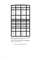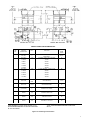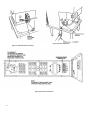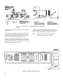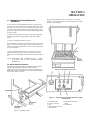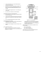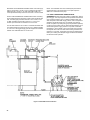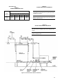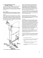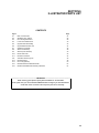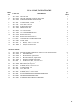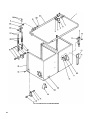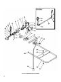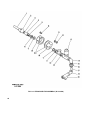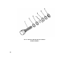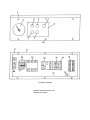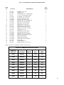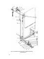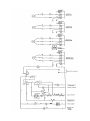
1
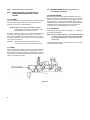
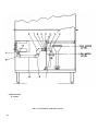
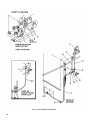
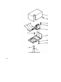
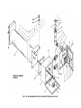
OWNER'S MANUAL
D-8/DD-8
HIGH TEMP
DISHWASHER
BLAKESLEE
1844 South Laramie Avenue
Chicago, IL 60804
Phone: (708) 656-0660
BLAKESLEE
66 Crockford Boulevard
Scarborough Ontario, Canada M1R 3C3
Phone: (416) 751-2625
Listed below are items NOT covered under warranty.
1. Lighting of Gas Pilots.
At the time of installation the gas pilots and burners should be adjusted. Continued failures of pilot lights would indicate dirty gas lines, improper
original adjustment or intermittent drafts blowing out the flame.
2. Replacing Fuses or Resetting Overloads.
Replacing a blown fuse or resetting an open overload breaker is a very simple procedure and is the owner's responsibility. If the machine
continues to blow fuses or open the overload breaker, contact you nearest authorized Blakeslee Service Center.
3. Adjusting Tank Heats.
Heat adjustments are covered in this Manual and must be adjusted depending upon desired results.
4. Proper Loading of Dishes.
It is important the machine owner's personnel observe the instructions outlined in paragraph 2-2.
5. Cleaning Drain Valves.
Foreign articles lodged in the drain valve seat should be removed as a part of normal daily cleaning.
6. Cleaning Rinse or Wash Nozzles and Line Strainers.
Keeping a dishwasher clean and removing obstructions from the nozzles and line strainers will be a periodic function of the machine owner's
personnel. The cleaning periods will vary depending upon impurities in the water supply and cleanliness of the washing operation.
7. Final Rinse Water. (High Temperature Dishwashers Only)
Most frequent of all complaints in any dishwashing machine is that of poor final rinse. It is the responsibility of the owner to provide 180° to 195°
(plus) water at 15-25 Ib. flow pressure through clean unobstructed water lines. If the machine has a factory equipped final rinse water booster,
the owner must supply the booster with a minimum of 140° temperature water.
8. Electric Boosters and Garbage Disposals.
Although these units may have been purchased with the machine, they are warranted by the individual manufacturer. Consult the nearest factory
authorized representative for these particular items.
9. Overtime Charges.
All warranty work is performed during normal daytime working hours (8 AM — 4:30 PM Monday through Friday). If warranty is requested at other
times, the owner will be required to pay the overtime premium for all labor charges.
10. Chemical Dispenser. (Low Temperature Dishwashers Only)
Replacement and lubrication of the blue hose used in the chlorine dispenser pump is a simple procedure and the owner's responsibility. Refer to
Owners Manual for further instructions.
Blakeslee
Service Department
TABLE OF CONTENTS
SECTION 1
DESCRIPTION
1-1
General Description
SECTION 2
INSTALLATION
2-1
2-2
2-3
2-4
2-5
2-6
2-7
2-8
2-9
2-10
2-11
2-12
2-13
SECTION 3
Plumbing and Electrical Connections
Location
Dish Table
Electrical Connections
Pump Rotation
Fill Rinse
Drains
Heating Systems
Electric Heater
Gas Heater
Steam Injection Heater
Steam Coil Heater
Electrical Detergent & Rinse Injector Connections
OPERATION
3
3
3
3
3
4
5
5
5
5
9
9
9
3-1
3-2
3-3
3-3A
3-4
3-5.
3-6
3-7
SECTION 4
Preparing Dishwasher for Operation
Auto Tank Fill
Timed Tank Fill
Tank Selection (DD-8 only)
Soiled Dish Table Operation
Loading Machines
Operating the Dishwasher
Shut down and Cleaning
MAINTENANCE AND LUBRICATION
11
11
12
12
12
13
13
14
4-1
4-2
4-3
4-4
4-5
4-6
4-7
SECTION 5
Motor
Pump
Doors
Wash Arms
Final Rinse Arm and Nozzles
Pump Motor Overload Protection
Troubleshooting
OPTIONAL EQUIPMENT
15
15
15
15
15
15
15
5-1
5-2
5-17
5-20
5-21
5-22
5-23
SECTION 6
General
Hot Water Boosters
Machine Mounted Booster
Automatic Tank Fill
Timed Fill
Door Safety Lock
Tank Selection (DD8 only)
ILLUSTRATED PARTS LIST
19
19
23
24
24
24
24
See Separate Table of Contents List
1
25
SECTION 1
DESCRIPTION
1-1. GENERAL DESCRIPTION
1-3. MOTOR
The machine door is counterbalanced and opens to provide easy
access to the inside of the machine.
Machine is equipped with a 1 HP 1725 RPM motor. D8's have one,
DD8's have 2.
The machine can be easily changed from a straight thru to corner
model by the simple movement of one track rail. (See Figure 1-1).
1-4. CONTROL CIRCUIT
If your machine is a single D8, and is to be used in a corner, the right
side must always be positioned against one wall (see Figure 2-5).
DD8 machines, if used in a corner, should have been ordered so that
the operating controls are placed in the control box of the tank that is
farthest from the corner. (Left tank or right tank.)
1-2. DOOR SAFETY SWITCH
All machines are equipped with a door safety switch. (See Figure 1 2). The machine will not operate when door is open. If the door is
accidentally opened during an automatic cycle, the machine
operation will stop. (Some models may be equipped with Optional
Door Safety Lock. See para. 5-22 for description of lock.) When the
door is closed, the operator must press the start button again to finish
the wash cycle. If the door was opened when the machine was in the
rinse cycle, the machine will automatically finish the rinse cycle when
the door is closed again.
Figure 1-1. Relocating Track to Convert Straight-thru to
Corner Model.
All machines are supplied with a 115 volt, A.C. control circuit.
1.5. VACUUM BREAKER
The fill line has a vacuum breaker installed in it to prevent any back
flow of water into the fresh water supply line. If a negative pressure
develops in the supply line, the loss of pressure permits a check
valve inside the breaker to drop, sealing the orifice while at the
same time a vent opens admitting air to the system to break the
vacuum.
1-6. HEATERS
Wash tank water is heated by electricity, steam coil, steam
injection, or gas. Electrically heated machines are available in 208,
240, 440, or 480 volts only.
Figure 1-2. Door Safety Switch
1
1.7. AUTOMATIC OR TIMED TANK FILLED
(Optional)
All machines can be supplied with an automatic or timed
tank fill. (See para. 5-20 & 5-21 for description).
1-8. Final Rinse Boosters (Optional)
Machine can be equipped with an optional built-in electric
booster, remote mounted electric booster, or remote
mounted steam booster. These boosters are designed to
raise rinse water temperature from 140° F to 180-195°.
(Refer to para. 5-2 for description).
Following are the complete assemblies needed for tank heat
conversion.
Natural Gas
L.P. Gas
Steam Injector
Steam Coil
Electric
W-0-17966
W-0-17967
W-3-12988
W-3-13129
W-0-95377
NOTE: Electric heat not available for 115 volt machines.
Additional conversion installation note.
1-9. Heat and Voltage Field Changeover
One of the most desirable features of the D8 Dishwasher is
it can easily be field converted to different tank heats and
voltage. All of the tank heats fit on the same mounting
bracket. All that is necessary to convert from one type of
heat to another is to order the kit for the type of heat desired
and make the wiring changes as described below, in the
parts list pages of this manual and the wiring diagram, W-317715. figure 15F-20 of Modular Dishwasher Service
Manual. (NOTE: to keep the cost of conversion as low as
possible, it will be necessary to purchase a few electrical
components such as flexible waterproof conduit, wire, etc.
locally).
2
When changing either to or from single to three phase electrical
power, the wash pump motor must be changed. The motor protection
fuses must also be changed. See parts description in figure 6-11 and
wiring diagram, figure 15F-20 of Modular Dishwasher Service
Manual.
When changing from 115 volts to 208, 230, 440, or 480 volts, single
or 3 phase, a transformer must be added. The motor protection fuses
must also be changed (see parts description in figure 6-11 and wiring
diagram, figure 15F-20 of Modular Dishwasher Service Manual.
SECTION 2
INSTALLATION
2-1. PLUMBING & ELECTRICAL CONNECTIONS
Various plumbing connections are tagged "180° water,"
"steam," "gas," etc.
NOTE: Installation must be made by qualified workmen observing all
applicable Sanitary, Safety & Electrical Codes.
2-2. LOCATION
Place dishwasher in its proper location. (See figure 2-5 or 2-6).
Maintain 34-1/4" ±3/4" height. (See figure 2-2). Level dishwasher by
turning adjustable feet. INITIAL SETTING OF DISHWASHER MUST
BE LEVEL TO PERMIT HOOD TO OPEN AND CLOSE PROPERLY. If
one side of the door has an excessive gap after the dishwasher is
leveled, adjusting one of the front legs up or down will remedy this.
(See figure 2-3). Do not make any service connections until machine is
set and leveled and doors open and close properly.
2-3. DISH TABLE
Dish table should be lipped into the dishwasher. (See figure 2-4). Use
silicone type sealer between dish tables and dishwasher. Secure with
stainless steel (S/S) truss head screws.
2-4. ELECTRICAL CONNECTIONS
Check machine data plate before making any electrical connections.
Connections must agree with data plate (figure 2-1) on machine. A
fused disconnect switch or circuit breaker (not furnished) MUST be
installed in the electrical supply line for the dishwasher. This service
connection must meet all national and local electrical code requirements. All connections are made at one common connection in control
box. (See figure 2-9). Control box cover is hinged. Remove the six 1/4
x 20 screws and swing cover open to the right. (See figure 2-9).
Figure 2-3. Attaching Table to Tank
NOTE:
CAUTION:
If machine has optional electrical booster, refer to section 5
for separate electrical connection information.
Before attempting to connect electrical service
connections, be sure incoming power is turned off.
2-5. PUMP ROTATION
The pump motor(s) must rotate in a clockwise direction (when facing
front of dishwasher). An arrow on the side of the motor(s) (see figure
2-7) indicates direction motor shaft(s) must turn for correct washing
action. This rotation is factory checked but must be rechecked before
using the machine.
Figure 2-1. Data Plate
3
NOTE:
Check both motors on Double D8.
NOTE:
ALWAYS DISCONNECT ALL POWER GOING TO
DISHWASHER BEFORE MAKING ANY OF THESE
CHANGES.
2-8. HEATING SYSTEMS - Refer to Figs. 2-6 and 2-7
For Installation Information
2-9. ELECTRIC HEATER
2-6. FILL RINSE
Final rinse water will be used to fill dishwasher. Therefore, this supply
line should have a water temperature of 180-195°F and a flow
pressure of 15 to 25 P.S.I, at the dishwasher.
NOTE: If machine is equipped with either a machine
mounted booster, or a remote mounted booster, water
supply temperature must be 140°F minimum.
If the supply pressure is below 15 P.S.I., an optional booster pump will
be required. If the supply pressure is over 25 P.S.I., a pressure
reducing valve (optional) will be required. Connect a 3/4" pipe to the
line strainer. (Figure 2-4). If the run is over 20 ft., use a larger pipe to
insure proper flow pressure.
CAUTION:
Before attempting to connect electrical service
connections, be sure incoming power is turned off.
Machines that are electrically heated are available in 208, 240 or
440-480 volts, single or three phase only. They are pre-wired at the
factory and only one common connection is necessary. LI and L2
for single phase, L1, L2 and L3 for three phase. (See figure 2-9.)
Additional instructions are inside the control box. Be sure wire size
is adequate to carry entire amperage toad. The temperature is
controlled by the thermostat located in the control box.
2-10. GAS HEATER
Check tag attached to gas valve for type of gas (L.P. or Natural) to
be used with the equipment.
NOTE:
Check that all fittings are tight. Connect gas supply to control valve,
conforming to all local codes.
2-7. DRAINS
Connect the tank drain(s) (figure 2-5 or 2-6) to the sew er connection
using 2" pipe (figure 2-8). Because of the hot water that is used in
dishwashers, grease traps are usually not very effective. If a grease
trap is required, it must be installed below the drain line and have a
capacity of 40 gallons per minute.
Figure 2-4
4
If tag is missing, Natural or L.P. gas can be determined
by checking the gas control valve. Natural gas valve
has a pressure regulator, L.P. gas does not. (See
figure 2-10.)
5
SERVICE CONNECTION INFORMATION
Service No.
Connection
180°F Hot
1 Water Inlet
Fitting
Function
Dim. from
Floor
Inches
3/4" NPT Fem.
Tank Fill and
Final Rinse
60-1/4"
1-1/8" Dia. Hole
1 HP Motor and
Controls
113/60/1
230/60/1
208/60/3
230/60/3
460/60/3
25"
2A Electric
12Amps
13 Amps
12 Amps
5.7 Amps
1-1/8"
Tank Heater
230/60/1
208/60/3
230/60/3
460/60/3
25"
3 Drain
2" NPT Male
Waste to Sewer
12-1/2"
4 Gas Inlet
1/2" NPT Fem.
Gas Tank Heat
10-1/4"
5 Gas Flue
19-3/4" x 1"
500 x 25 mm
Gas Burner Vent
16"
Steam 6
Injector
3/4" NPT Fem.
Steam Tank Heat
10"
Steam 7
Coil-In
3/4 "NPT Fem.
Steam Tank Heat
10"
Steam 8
Coil-Out
1/2" NPT Fem.
Steam Tank Heat
10"
9 140°
Water
Inlet
3/4"
Tank Fill &
Booster Inlet
5-3/4"
1-5/16"
Blakeslee
Built-in Booster
230/60/1
208/60/3
230/60/3
460/60/3
5-3/8"
2 Electric
15 Amps
7.5 Amps
4 Amps
3-8 Amps
1.9 Amps
10 Electric
60 Amps
39 Amps
34 Amps
16 Amps
Tank requires 18.5 gallons of hot water to fill. Final rinse requires
maximum of 130 gals per hour of 140° hot water at 20 P.S.I. Total
steam requirement 25 Ibs. cond/hr at 20 P.S.I.
Gas burner flue not furnished on steam or electrically heated
machines. When gas heated machines are specified dimensions
marked ** are increased by 2" (50 mm).
Figure 2-5 (Continued from previous page)
6
SERVICE CONNECTION INFORMATION DD8
MK.
NO.
SERVICE
CONNECTION
FITT.
180° MIN.
1"
ELECTRIC
1-1/8"
FUNCTION
TANKS FILL INLET AND FINAL
RINSE INLET
CONTROL PANEL AND 2 MOTORS
30 AMPS
115/60/1
15AMPS
230/60/1
8 AMPS
208/60/3
7.2 AMPS
230/60/3
3.6 AMPS
ELECTRIC
DIM.
FROM
FLOOR
60-1/4"
25"
460/60/3
1-1/8"
2 TANK HEATERS - TOTAL 5.0 KW
24 AMPS
230/60/1
26 AMPS
208/60/3
24 AMPS
230/60/3
11.4 AMPS
460/60/3
25"
GAS INLET
1/2" NPT
FEM.
GAS TANK HEAT
10-1/4"
GPS FLUE
19-3/4"
GPS BURNER VENT
16"
(2) DRAINS
2"
CONNECTS TO WASTE
12-1/2"
STEAM
3/4"
TANK HEAT-INJECTOR
10"
STEAM
3/4"
TANK HEAT-COIL-IN
10"
STEAM
3/4"
TANK HEAT • COIL-OUT
10"
TANKS REQUIRE 37.0 GAL'S OF HOT WATER TO FILL.
FINAL RINSE REQUIRES MAX. OF 260 GAL'S PER HOUR
OF 140° HOT WATER.
TOTAL STEAM REQUIREMENT 50 LBS. COND./HR AT
20 P.S.I.
Figure 2-6. DOS Rough In Information
7
Figure 2-8. Drain Installation
Figure 2-7. Motor Rotation Checking
Figure 2-9. Power Connections
8
Natural gas valve has a pressure regulator for minor adjustment. L.P.
Gas pressure must be regulated by the customer's pressure
regulator.
flame. BE SURE TO replace cover screw after adjustment to prevent
possible gas leakage.
GAS VENTS
Gas heated machines are furnished with flues. These do not have to
be connected to any vents. The temperature is controlled by the
thermostat located in the control box.
2-11. STEAM INJECTION HEATER
Connect incoming steam line to steam line tagged "incoming steam".
This will be the line strainer. It is recommended that a steam shut-off
valve and pressure gauge (not supplied with machine) be installed close
to the dishwasher for servicing. The tank water temperature is controlled
by the thermostat located in the control box. (See figure 2-9).
2-12. STEAM COIL HEATER
PILOT LIGHTING PROCEDURE
1.
Slightly depress control knob and turn clockwise to OFF. Wait
5 minutes for all unburned gas to vent. REMEMBER that L.P.
gas does not vent upward naturally. Therefore, if you have
been unsuccessful in lighting the pilot, within a short period of
time, the area must be exhausted with a fan, or equivalent, to
blow out L.P. gas before attempting to relight the pilot.
Connect incoming steam line to line tagged "steam supply." This will
be the line strainer. It is recommended that a steam shut-off valve and
pressure gauge (not supplied with machine) be installed close to the
dishwasher for servicing.
Connect condensate return line to condensate trap.
CAUTION:
CONDENSATE LINE MUST RUN PARALLEL OR
DOWN FROM THE DISHWASHER. IF CONDENSATE
LINE HAS TO BE RUN VERTICAL, A CONDENSATE
PUMP MUST BE INSTALLED.
2.
Turn the control knob to PILOT, depress it completely, and
light the pilot burner. The knob must be held down about 1
minute before the pilot burner will stay lit after releasing the
knob.
The tank water temperature is controlled by the thermostat located in
the control box. (See figure 2-9.)
3.
Turn the knob to ON, and set the thermostat located in control
box for desired wash tank temperature (150-160'F).
2-13. ELECTRICAL DETERGENT & RINSE
INJECTOR CONNECTIONS
CAUTION:
NOTE:
DO NOT TURN GAS HEAT ON UNTIL WASH TANK
IS FILLED WITH WATER.
Main burner is equipped with a non-adjustable orifice
(0.052 for L.P. gas and 0.078 for Natural gas.)
PILOT FLAME ADJUSTMENT
The pilot flame should envelop 3/8 to 1/2 inch of the tip of the
thermocouple (figure 2-11). Remove pilot adjustment cover screw
(figure 2-10). Turn inner adjustment screw clockwise to decrease or
counterclockwise to increase pilot
WARNING:
DISCONNECT ALL POWER BEFORE MAKING
ANY ELECTRICAL CONNECTIONS.
Connect primary leads of detergent-rinse injector transformer to F1
and F2 (top side of fuse block). (See figure 2-15. page 10.) POWER IS
AVAILABLE AT THIS POINT DURING THE WASH CYCLE.
The voltage at this point is the same as the primary (incoming)
machine voltage. Customer's incoming power line provides fuse
protection.
DO NOT connect detergent equipment to lines IT1 or IT2 or any other
source. This will defeat the fuse protection for the pump motor and
VOID the machine WARRANTY.
Connect secondary leads of detergent-injector transformer to
dispensing equipment.
A connection tap is provided for fresh water for detergent and final
rinse equipment (see figure 2-12).
Figure 2-11. Pilot Flame Height
9
Figure 2-12, 2-13 and 2-14 is not applicable for current production
models.
A connection tap is provided for the injection of final rinse additive
(see figure 2-12)
There is also a prepunched hole on the front of each dishwasher
tank - adjacent to the right side of the dishwasher pump motor.
This is for the detergent probe. (See figure 2-13). This hole was
put on all machines shipped after approximately 6-1-81.
Connect secondary leads of detergent-injector transformer to
dispensing equipment. A detergent equipment control box knockout
for 1/2" conduit is located next to the incoming power knockout.
NOTE:
It is highly recommended that a separate detergent
dispenser be used for each tank of a DD8.
Before 6-1-81 there were prepunched holes on the side of the
dishwashers for detergent probes (see figure 2-14). These holes
are covered with carbon steel caps. If these holes are not used,
replace the caps with stainless steel caps.
Figure 2-15. Detergent Injector Hook -Up
10
SECTION 3
OPERATION
3-1. PREPARING THE DISHWASHER FOR
OPERATION
the top of the standpipe as long as the machine is on. When the
machine is cycled, the final rinse water will bring the wash water up
to the lop of the standpipe.
a. Close drain (s) by turning handle of drain valve (see figure 2-8)
clockwise as far as it will go. Be sure standpipe guide is in position.
(See figure 3-1), Place scrap screens in position. (See figure 3-2). Be
sure all wash arms and lower final rinse arm(s) are in position and
spin freely. Tighten (turn clockwise) lower spindle and upper wash
rotor nut by hand.
b. Scatter the initial charge of detergent in scrap trays. Replenish as
needed unless automatic detergent dispenser has been added by
others.
c. Close the counterbalanced three way door.
d. Fill dishwasher tank with water. Flip HEAT/FILL switch item 4.
Figure 3-3 to "FILL" (down) position. Leave it in this position for 3
minutes to fill tank. Flip HEAT/FILL switch to "ON" (up) position
to turn on tank heater.
e. Observe wash tank thermometer item 6, figure 3-3. It should
)
)
register between 150 -160 F. If. after a short period of time. this
temperature is not attained adjust thermostat in control box (figure 29.)
NOTE: ADJUSTING THE THERMOSTAT IS A USER
FUNCTION AND IS NOT COVERED UNDER
WARRANTY.
3-2. AUTO TANK FILL-Optional
If machine is equipped with optional automatic tank fill. machine
will start filling with water automatically when machine
"HEAT/FILL" switch is flipped "ON" (up). Wait approximately 3
minutes for machine to fill. NOTE: This option will automatically
keep water to within 3 inches of
Figure 3-2. Installing Scrap Screens
Figure 3-3. Standard Front Panel and Thermometer Single
and Double D8
1. Red Power Light
5. Cycle Start Push Button
2. Amber Cycle Light
Switch
3. Fuse
6. Thermometer
4. Heat On/Manual Fill and
Rinse Switch
Figure 3-1. Standpipe Guide
3-3. TIMED TANK FILL (Optional)
HEAT/FILL switch, for this option, is a spring return type. To
activate Timed Tank Fill flip HEAT/FILL switch to "FILL"
position and hold for 2 seconds. Switch will return to "OFF"
position by spring action. Timer continues to fill tank.
NOTE: This lever should only be depressed at beginning of an
operation when the machine does not have any water in it. After
the machine is operating the final rinse water will keep the tank full
of water.
3-3A. TANK SELECTION (Optional on DD8 Only)
This option enables either left, right or both tanks to be
operated during each automatic or manual cycle. It
enables an operator to cycle only one tank during non
rush periods. In most cases, it also enables the machine
to operate on one tank even if the second tank is
inoperable.
3-4. SOILED DISHTABLE OPERATION
If your dishroom personnel observe these simple work rules,
your dishwashing operations will be fast and smooth, and
your dish breakage held to a minimum.
Instruct your bus boys or waitresses that leftover food must
be removed from dishes before placing them in stacks. See
figure 3-5. This will assure maintaining cleaner wash water
and reduced detergent costs.
Certain items are self-stacking, such as plates or trays. Food
soil should be removed from these items and the plates should
be placed in manageable stacks. An area on the soiled dish
table should be designated as a "build-up-area." The stacks of
dishes should be held in the build-up area and, if possible,
stacks of like items should be placed next to each other.
Racks can then be filled with like items when operator begins
washing.
Figure 3-3A. Front Panel and Thermometer
(Shown with optional tank selection switches)
DD8 Only
Some items will not readily stack, such as coffee cups,
glasses, soup bowls. These items should be placed directly
into racks so that they can be transported with a minimum of
effort. See figure 3-6. In racks these items also are not
exposed to breakage. Racks, when filled, should be placed in
the build-up area. This organized, orderly separation of
tableware is essential to dishroom efficiency and reduced
breakage. THE BETTER ORGANIZED YOUR SOILED
DISHTABLE, THE FASTER YOUR ENTIRE
OPERATION, AND THE LESS YOUR BREAKAGE
COSTS.
Silverware should be soaked in a sink or container to keep
food particles from drying. When ready for washing, the
Figure 3-5. Scrapping Dishes before Stacking
Figure 3-4. Hosing Inside of Tank
12
3-6. OPERATING THE DISHWASHER
a. After filling the wash tank and adding detergent, raise the
door and slide the rack into the dishwasher. (Center of both
tanks in a DD8.)
b. Close the door (dishwasher has a safety switch figure 1 -2
that will prevent the machine from operating if the door is
open.)
Figure 3-6. Build-up Area
silverware should be placed either in a flat rack or vertical silverware
holder and sent through the dishwasher.
NOTE: When placing silver in flat racks, do not overload the rack. You
should be able to see the bottom of the rack in many places after it is
loaded.
IMPORTANT: As much as possible, keep soil from entering
dishwashing machine. This will reduce detergent consumption and will
make the machine easier to clean.
3-5. LOADING MACHINES
All plates of the same size should be washed at the same time to
eliminate sorting dishes at the clean end of the machine. If possible, all
glasses, cups, etc. should likewise be sent through the machine at the
same time to eliminate rack sorting. The machine should be operated
as close to 100% efficiency as possible for a brief period while the
build-up area is being cleared. Dishes from the build-up area should be
quickly processed through the machine so the loading operator can
return to his normal scrapping and stacking function.
Better results can be obtained from a DD8 dishwasher if one tank is
used exclusively for china and the other tank is used for glasses and
silver.
c. Automatic Operation
Momentarily depress START button. Machine will automatically wash and rinse one rack of dishes. Automatic CYCLE
light (figure 3-3) will be on during the entire automatic cycle.
When the cycle is over, the light will turn off. If the door is
opened during the automatic cycle, the machine will stop. The
automatic cycle will have to be restarted when the door is
closed again. This feature provides a complete cycle to insure
proper cleaning of the rack of dishes or added articles.
To avoid being splashed, it is advisable to wait approximately
5 seconds before opening the door, after stopping the machine.
d. Manual Operation
Wash Cycle
The only time manual wash is necessary is because of a timer
or some other electrical failure. Close the hooded door, flip
HEAT/FILL switch to "ON," depress and hold START button.
Minimum wash time is 45 seconds.
Rinse
On some rare occasion, it may be desirable to operate the
rinse cycle longer than programmed in the timer. Simply flip
the HEAT/FILL switch to "FILL." Machine will rinse as long as
the switch remains in the "FILL" position. Not applicable with
machine equipped with Timed Tank Fill (Optional). If the
machine timer has failed and the machine is being operated
manually, the ware must be rinsed for a minimum of 12
seconds after a normal wash cycle.
Figure 3-7. View of Racks with Door Raised (DD8)
13
3-7. SHUT DOWN and CLEANING
a. Turn off main power switch.
b. Flip HEAT/FILL switch to "OFF" position.
c. Drain machine by turning drain valve counterclockwise as far as it
will go (figure 2-8). Raise washer door.
d. Clean your dishtables and rinse in fresh water. Be sure to leave
scrap screens in machine while doing this.
e. REMOVE scrap screens, empty them, and clean with a scrub
brush in sink. Place on dishtable. DO NOT hit sides of scrap screens
on trash containers.
f. Inspect Revolving Wash Rotors for blockage of any opening and
ease of rotation. Remove and clean if required (see para. 4-4.)
g. Lift retainer on stand pipe guide (figure 3-1).
14
Remove standpipe and screen. Clean thoroughly in water
with wire brush.
h. Wash and clean INSIDE OF MACHINE using a hose. (See
figure 3-4.)
i. Leave DOOR open to dry interior of machine.
j. Thoroughly clean dishwashing area.
k. Clean and refill Detergent Dispenser (if machine has this
optional equipment) as instructed by your detergent supplier.
I. Replace standpipe and screen, flip stand pipe retainer lever
in place.
Additional Blakeslee Racks
W-0-16428 .............. Multipurpose Rack
W-0-16429 ................ Combination Rack
SECTION 4
MAINTENANCE & LUBRICATION
IMPORTANT:
4-1. MOTOR
No Lubrication required
4-2. PUMP
No Lubrication required
4-3. DOORS
No Lubrication required
4-4. WASH ARMS
a. Wash arms (upper and lower) should turn freely and
continue turning for a few seconds after being whirled by
hand.
b. If the scrap screens are not properly in place, obstructions,
such as prune seeds or bones, may clog the wash arm nozzles.
The wash arms are easily removed for cleaning.
c. To remove the lower wash arm, first lift off the rinse arm, then
unscrew the spindle bearing pin (item 8, figure 6-4). Lift off lower
wash arm.
4-7. TROUBLESHOOTING
WASH PUMP MOTOR WILL NOT START (EITHER
TANK)
1. Automatic timer defective.
Operate wash pump manually (see paragraph 3-6d). If pump will
run on manual but not automatic, this indicates a defective timer.
2.
d. The upper wash arm(s) is removed by removing the wash
rotor nut (item 12, figure 6-6).
a. The rinse nozzles will need frequent cleaning if the water
contains much lime or other solids.
c. The upper final rinse nozzles can be cleaned with a wire brush
and by inserting the end of a paper clip thru the nozzle. Then
remove the 1/2" pipe cap at the end of the final rinse line and
flush out the line (item 28, figure 6-5).
4-6. PUMP MOTOR OVERLOAD PROTECTION
a. Wash Motor(s)
Wash Motor protection is provided by Slow -Blow type cartridge
fuses. In the event a foreign article jams the pump impeller, the
motor will draw an excessive amount of current and open (blow)
the fuse(s). After clearing the foreign article from the pump, the
fuse(s) must be replaced before the pump motor will operate.
WARNING:
Motor overload fuses blown.
Check the three fuses for continuity (see items 1 thru
3, figure 6-11).
Check junction box above motor if not working.
NOTE: If overload fuses are blown (open) this indicates either a
defective motor or a foreign object has jammed the pump
impeller. Turn off power supply, drain tank and check and
remove any obstruction in the tank and pump intake.
4-5. FINAL RINSE ARM & NOZZLES
b. The hole in the rinse nozzle on the lower rinse arm may be
cleaned with a wire and paper clip. Push the scale or obstruction into the rinse arm, then unscrew the end plugs and
flush out the tubes by operating the rinse. The lower rinse arm
may be lifted straight off the bearing pin and thrust washer
assembly.
An open (blown) fuse must always be replaced
with the same size and type of fuse(s).
INCREASING THE FUSE SIZE OR RATING WILL
ELIMINATE THE MOTOR PROTECTION AND
VOID THE MACHINE MOTOR WARRANTY. Refer
to figure 6-11, items 1 thru 3A, for the proper fuse
size. It is suggested that spare fuses be purchased
and kept on hand. These fuses can be obtained
from your Blakeslee parts distributor or authorized
service agency. Refer to the authorized service
distributor and service agency listing booklet that
was packaged with the machine for the one in your
area.
MACHINE WILL NOT START
1. Main source of power off. Check power supply from customer's
fuse or circuit breaker.
2.
Control fuse blown open. Check control fuse for , continuity.
3.
Door safety switch not actuated or defective. Be sure door is fully
closed and rear portion of door handle has activated (closed) the
switch. (See figure 1-2).
NO TANK HEAT
1.
HEAT/FILL switch not "ON" or defective. Flip the switch to "ON"
position. If red "POWER" light comes on, switch is good. Check
further.
2.
Main gas valve, steam valve or electrical heating circuit breaker
not turned on. Check.
SEE FIGURE 6-11, ITEM 29 FOR LOCA TION OF FUSES.
15
3. Thermostat set too low or defective. Open control box and turn
thermostat clockwise until heat comes on.
10. Dishes or silver improperly racked. Refer to para. 3-4 for
operating instructions.)
NOTE:
11. Poor final rinse. Refer to para. 2-6.
If heat comes on, do not leave thermostat at this high setting.
Adjust to obtain 150°-160°F wash tank temperature on wash
tank thermometer (figure 2-12, page 8). If turning thermostat
clockwise does not start the heating cycle, check for the
following::
a.
Defective thermostat
b. Defective Gas valve
c. Steam solenoid or heating contactor, whichever is on your
NO FINAL RINSE
1.
Line strainer dirty or sticking final rinse solenoid
valve. For proper operation, the solenoid valve must be free of
foreign material at the valve seat. A critical period for a valve is
soon after installation. Pipe compound or metal shavings from
the installation may lodge at the valve seat and prevent the
valve from completely opening or closing. A dirty line strainer
(see figure 2-4) will also allow foreign material to pass.
machine.
d. Dirty line strainer
e. Steam pressure too low (should be 10 Ibs. min.)
f. Defective steam trap (steam coil heated machine only)
NOTE: The heater is designed to maintain a temperature only. Door of
dishwasher should always remain closed when machine is on
but not being used.
REMEDY
Shut off the water supply and using a wrench, unscrew the end of the
line strainer and drain. Clean and replace line strainer and cap.
Operate final rinse. If final rinse still does not operate, turn water
supply off again and unscrew bonnet of solenoid valve and clean. If
after doing the above, the final rinse continues to malfunction, call your
Blakeslee service technician.
WASH TANK WATER FOAMING
1.
Wash tank water very dirty. Change wash tank water.
INSUFFICIENT RINSE TEMPERATURE
Final Rinse
1.
Final rinse booster turned off (remote mounted booster only).
2.
Poor pre-scrapping procedure. Scrap dishes better.
2.
Separate electrical supply to electric booster turned off.
3.
Excessive protein being put into dishwasher.
3.
Booster inoperative or booster thermostat set too low.
4.
Improper detergent. Check with detergent representative.
4.
Adjust thermostat (refer to figure 2-9). Optional equipment
(see section on boosters).
POOR WASHING RESULTS
1.
Poor scrapping procedures. Scrap dishes better.
5.
Water temperature of building supply water to booster too low.
2.
Scrap screens blocked with soil. Empty screens.
6.
Water supply line pressure from booster to dishwasher too low
or not insulated to prevent heat loss.
3.
Machine water dirty or contaminated. Change water.
4.
Wash tank water temperature too low (See section 2-8)
5.
Detergent dispenser empty. Fill dispenser.
6.
Pump impeller clogged. (Refer to para. 2-5 pump motor.)
7.
Wash pump running backwards. (Refer to para. 2-5 for pump
rotation.)
8.
Wash rotor clogged and/or not rotating. (Refer to para. 4-4
on wash rotor.)
POOR FINAL RINSE RESULTS
1.
Water supply pressure too low (must be 15-25 Ibs. flow
pressure) (See para. 2-6.)
9.
Water conditioner causing spotting. Consult with detergent
representative.
2.
7.
16
Steam boosters only.
a. Insufficient steam supply to booster (minimum of 10
Ibs. flow pressure required).
a. Defective steam trap.
c.
Condensate line not level or going down.
DD8 supply line size too small. Flow rate for DD8 is 18 GPM.
Incoming water supply line should be 1" inside diameter.
3.
Final rinse temperature too low. (See troubleshooting NO
FINAL RINSE TEMPERATURE.
4.
High time content or other foreign material in the water. High
lime content or other foreign material will cause severe
spotting. Consult your detergent representative for possible
remedies.
5.
Final rinse nozzles clogged. See para. 4-5 on cleaning final
rinse nozzles.
6.
Dirty wash water in dishwasher. Clean dishwasher.
DISHWASHER TANK(S) NOT HOLDING WATER
1.
Drain valve(s) open or not fully closed. Turn valve(s) clockwise
until it hits a positive stop.
2.
Foreign material around drain seat preventing positive sealing
of drain plug. Clean dishwasher and drain screen. (See para.
3-7).
3.
Worn or damaged standpipe drain plug. Clean or replace.
Figure 4-1. Vacuum Breaker
DISHWASHER WILL NOT DRAIN
1.
Clogged drain screen. Empty dishwasher by bailing water out
of wash tank with pan, etc. Clean screen.
2.
Customer's drain line plugged or too small. Consult your local
plumber.
VACUUM BREAKER LEAKING
1.
Deposits on the float will prevent operation of the vacuum
breaker. Shut off water supply and remove the threaded top cap
(4) (figure 4-1). Lift off the
collar (5) with the "0" ring (2), then remove the gasket
(1). Withdraw the float (3) and clean thoroughly. At
reassembly, make sure the "0" ring is not damaged and
is properly seated in its groove.
Genuine Blakeslee Repair Kits that are available for these
vacuum breakers:
W-1-12357 (Sloan Valve)
W-1 -12351 (Febco Valve)
W-1-14835 (Consolidated Valve)
Please specify if your valve is manufactured by Sloan or
Febco. You will find the name on the cap.
17
SECTION 5
OPTIONAL EQUIPMENT
5-1. GENERAL
Extra equipment for the D8 dishwashing machine, available from
Blakeslee includes hot water boosters, automatic tank fill, timed fill,
etc. This section contains information regarding proper use and
maintenance of this equipment.
5-2. HOT WATER BOOSTERS
The hot water booster is used to raise the final rinse water temperature
to 180°F-195°F, which is the temperature recommended by the
National Sanitation Foundation and required by many health
departments. To attain this temperature, the water supply to the
booster must be maintained at 140°F. Three types of boosters are
available. (1) Remote mounted electric, (2) steam boosters and (3)
machine mounted electric boosters. (D8 only)
NOTE: If the temperature of the incoming water is less than 140°F,
an oversize electric booster will probably be necessary.
5-3. Steam Hot Water Booster (Model CD
LIME DEPOSITS. If lime deposits are a problem in your area, every 9
to 12 months delime the booster heat exchanger. Remove the heat
exchanger and submerge it in a tub of deliming solution. Follow the
instructions of the deliming product manufacturer for mixing the
solution and for length of time of soaking; 48 to 60 hours soaking
time is generally required. After soaking, be sure to wash and rinse
the heat exchanger thoroughly before installing it on the booster.
5-8. ADJUSTMENTS
THERMOSTAT. Remove cover of thermostat encloser (8, figure 5-1).
Turn thermostat adjusting screw clockwise to increase temperature,
and counter-clockwise to decrease.
PRESSURE REGULATOR. If the final rinse flow pressure is not
between 15 and 25 psi, adjust the pressure regulator (5, figure 5-1)
observing the following:
a. Loosen the 1/2" lock nut. Flip HEAT/FILL switch to "FILL" position.
5-4. STEAM LINE. The steam inlet line is equipped with a line strainer
(1, figure 5-1) and solenoid valve (2); the solenoid valve is controlled
by an electric thermostat. A steam trap (3) on the steam outlet assures
efficient heating. Periodic cleaning of the strainer is recommended. No
operator control of this system is required.
b. With the final rinse water flowing through the pressure regulator,
adjust to the correct pressure.
5-5. HOT WATER INLET LINE. The inlet piping contains a line
strainer (4), pressure gauge(6), and pressure relief valve (7). Periodic
cleaning of the line strainer is recommended. The pressure regulator is
adjustable (see paragraph 5-8). The pressure gauge indicates the flow
pressure of the final rinse water when the final rinse is in operation.
The gauge should be observed periodically to assure good final rinse
action. Good final rinse results are obtained when the flow pressure is
between 15 and 25 P.S.I., preferably 20 P.S.I.
d. After the proper pressure is attained, hold the 1/2" square head
screw in place and tighten the lock nut.
To prolong the life of the gauge, turn gauge cock (9), off (Lever
horizontal) when not observing pressure.
5-6. HOT WATER OUTLET LINE. The thermostat sensing bulb is in
the hot water outlet line. See paragraph 5-8 for adjustment.
5-7. CLEANING
LINE STRAINERS. The water outlet and steam inlet line strainers
protect the solenoid valves from dirt. Every month, clean the strainer
as described under TROUBLESHOOTING, "No Final Rinse". Be sure
water and steam supplies are turned off and pipes are cool.
18
c. To increase the flow pressure, turn the screw clockwise. Turning
the screw counterclockwise will decrease the flow pressure.
5-9. INSTALLATION
Position the booster so that pressure gauge can be observed by
machine operator. Use the adjustable feet on the booster to level the
unit. Figure 5-2 indicates dimensions for the plumbing connections.
BOOSTER LOCATION. Booster location with respect to the steam
supply, hot water supply and dishwashing machine is important for
efficient booster operation. Position the booster as close to these
items as possible. If the booster is positioned 20 feet or more from
the dishwasher, though the final rinse water is 180°F when it leaves
the booster, the exposed piping through which the water travels will
cool the water. The same situation applies to the booster hot water
supply. Similarly, when steam is carried over a long distance through
an exposed pipe, a pressure loss and temperature loss results. The
booster cannot operate effectively with long distances of exposed
piping. If the booster is located too far from the dishwasher, it is
recommended that an optional final rinse low temperature control be
installed in the dishwasher.
1. STEAM INLET STRAINER
2. SOLENOID VALVE
3. STEAM TRAP
4. HOT WATER STRAINER
5. PRESSURE REGULATOR
6. PRESSURE GAUGE
7. PRESSURE RELIEF VALVE
8.THERMOSTAT
9.GAUGE COCK
Figure 5-1. Steam Hot Water Booster
19
BOOSTER TO DISHWASHER CONNECTIONS. Final rinse supply
piping is 3/4 inch N.P.T. for D8,1" N.P.T. for DD8. Connect wires of
steam solenoid (2, figure 5-1) to wires marked #2 and #4 in the
control panel terminal strip. Protect the wires with a 1/2 inch conduit.
SUPPLY AND CONDENSATE CONNECTIONS. When connecting
the hot water and steam inlet piping, include a shut-off valve at each
inlet. The water piping must be a minimum of 3/4". For D8,1" N.P.T.
for DD8. The steam pipe must be a minimum of 1-1/2" for a C1
booster. Pipe sizes must be increased on runs over 50 ft.
The hot water inlet tee is 3/4 inch N.P.T. The steam inlet strainer size
is as follows: Model C1 booster is 3/4 inch N.P.T.; Model C2 booster
is 1 inch N.P.T. We suggest supply pipes be wrapped with insulation
material. The condensate return is 1/2 inch N.P.T.
NOTE: The condensate return line must always be pitched down.
Condensate return lines that are level or run uphill require the
addition of a condensate return pump.
5-10. SUPPLY PRESSURE AND TEMPERATURE REQUIREMENTS. Booster output (180°F water) is measured in gallons
per hour (gph). The output requirement for a particular machine is the
sum of final rinse water (in gph). To obtain a desired output, inlet
water temperature and steam supply pressure must correspond as
indicated in the booster sizing chart. For example, the model C1
booster is capable of providing 250 gph (at 20 pounds flow pressure)
of 180°F final rinse water when the inlet water temperature is 140°F
and the flowing steam supply pressure is 5 pounds. If inlet water
temperature is 120°F instead of 140 F, the booster will not produce
the required 180 F final rinse water without raising the steam flow
pressure to 7.5 pounds. The booster sizing chart is included here to
assist you in making sure adequate supply conditions are available
for effective booster operation.
Figure 5-2. Steam Booster Installation
20
Previous Page
TABLE 5-1.
STEAM BOOSTER SIZING CHART
Gallons Per Hour 180°F.
Steam
Pressure
5 Ib.
10 Ib.
15 Ib.
Rinse with supply water at temperatures shown
C1 BOOSTER
100°F
120°F
140°F
150°F
175
215
250
270
240
300
370
400
300
360
470
510
TABLE 5-2.
D8 FINAL RINSE WATER CONSUMPTION
Maximum Amount of Final Rinse Water Consumed per
Cycle @ 20 Lbs. Flow Pressure is 1.3 gallons (Flow rate is
1.4 Gallons Per Minute).
Maximum Amount of Cycles (55) Per Hour will consume 72
gallons of water per hour.
TABLE 5-3.
DD8 FINAL RINSE WATER CONSUMPTION
Maximum amount of final rinse water consumed per cycle @ 20
Ibs. flow pressure is 2.6 gallons (flow rate is 2.8 gallons per
minute.
Maximum amount of cycles (55) per hour will consume I 44
gallons of water per hour.
Figure 5-3. Remote Electric Booster Installation
21
5-11. Remote Electric Hot Water Booster
This electric hot water booster uses electric heating elements to heat
the final rinse water. The elements are controlled by a thermostat.
When installing, make provisions for future service especially access
to front cover assembly. Whenever possible, connect the machine
using pipe unions.
corner of front of booster and turn thermostat knob clockwise to
increase temperature, and counter-clockwise to decrease.
PRESSURE REGULATOR. If the hot water supply flow pressure is
not between 15 and 25 psi, adjust the pressure regulator observing
the following. Same as steam booster adjustment (paragraph 5-8.)
To increase the flow pressure, turn the screw clockwis e. Turning the
screw counterclockwise will decrease the flow pressure.
5-12. HOT WATER INLET LINE. The inlet piping includes a pressure
regulator, pressure-temperature gauge, and a relief valve. The
pressure relief valve is preset and requires no further adjustment. The
pressure-temperature gauge should be observed periodically during
final rinse operation. If the temperature indication is below 140 F, the
hot water source may not be hot enough for the booster to be
effective; the temperature of the hot water entering the booster may
have to be raised to 140°F. (NOTE: Refer to electric hot water
boosters water temperature recovery. Table 5-4 and to D8 final rinse
water consumption Table 5-2 or DD8 final rinse water consumption
Table 5-3. Similarly, the hot water supply pressure must be
maintained between 15 and 25 psi. The pressure regulator is
adjustable (paragraph 5-15). It may be that the booster is too small
and a larger booster should be installed.
HOT WATER OUTLET LINE. The outlet piping connects to a strainer,
gauge cock and solenoid valve shown in figure 5-3. Periodic cleaning
of the strainer is recommended. The gauge cock is provided for use
as described in paragraph 5-5. The thermostat is adjustable (refer to
paragraph 5-15).
5-16. INSTALLATION
Use the adjustable legs on the booster to level the unit. Figure 5-3
indicates dimensions for the plumbing connections.
BOOSTER LOCATION. Booster location with respect to the hot
water supply and dishwashing machine is important for efficient
booster operation. Position the booster as close to these items as
possible. If the booster is positioned 20 feet or more from the
dishwasher, though the final rinse water is 180°F when it leaves the
booster, the exposed piping through which the water travels will cool
the water.
The same situation applies to the booster hot water supply. The
booster cannot operate effectively with long distances of exposed
piping.
PIPING CONNECTIONS. The controls described in paragraph 5-12
are shipped as separate items. Figure 5-3 indicates the proper
sequence for connecting these items. Use 3/4 inch N.P.T. size fittings
and pipe for D8, 1" N.P.T. for DD8. Include a shut-off valve at the hot
w ater inlet as indicated in the figure. We recommend the hot water
supply piping be wrapped with insulation material.
5-14. CLEANING
LINE STRAINER. The water outlet line strainer protects the solenoid
valve from dirt. Every month, clean the strainer as described in
paragraph 5-7. Be sure water supply is turned off and pipe are cool.
When making a new installation the sediment and mineral deposits in
the existing lines, will probably break loose and clog the dishwasher
line strainer. Clean the strainer daily until this condition clears up.
ELECTRICAL CONNECTIONS. Connect control wires of the booster
to wires No. 2 and No. 4 in the machine control panel (as noted in
wiring diagram). Protect control wires in electrical conduit. Connect
the booster power wiring to a properly rated power supply, properly
fused, and properly protected in conduit.
5-15. ADJUSTMENTS
THERMOSTAT. The thermostat is pre-set at factory and should
require no further adjustment. Should minor adjustment be required,
remove cover located on lower right-hand
TABLE 5-4
ELECTRIC BOOSTER TEMPERATURE RECOVERY TABLE
(IN GALLONS PER HOUR)
22
DEGREE
FAHRENHEIT
RISE
40°
50°
60°
70°
80°
90°
100°
110°
120°
130°
140°
10.5 kw
12 kw
13.5 kw
15 kw
17kw
18 kw
24 kw
27 kw
30 kw
108
123
138
154
176
184
246
276
308
86
99
111
123
142
148
197
223
246
72
82
92
103
118
123
164
185
205
62
70
79
88
101
105
141
158
176
54
62
69
77
88
92
123
138
154
48
55
62
68
79
82
109
123
137
43
49
55
62
71
74
99
111
123
39
45
50
56
64
67
90
101
114
36
41
46
51
59
62
82
92
103
33
38
43
47
55
57
76
85
94
31
35
40
44
51
53
70
79
88
5-17. MACHINE MOUNTED BOOSTER
(Available on D8 Only)
A machine mounted booster is bolted under the left front of the D8
machine. This unit uses electric heating elements to raise the
temperature of the hot water from 140°F to 180-195°F. When
installing the D8 be sure not to obstruct the front of the booster or the
control box located next to the booster so that these components can
be serviced.
5-18. Installation
This unit is a low pressure, semi closed heater tank. One end must
always be open to the atmosphere. During installation of machine, do
not connect electrical power to booster until plumbing to booster is
completed.
Hot water inlet (pressure line) must always connect to line strainer,
pressure regulator, gauge and solenoid valve (see figure 5-4) which is
supplied with the unit. Water inlet plumbing can be changed from left
to right as desired. Inlet plumbing on a standard machine enters from
the left (when facing front of machine) as shown in figure 5-4. If right
hand inlet is required, the 3/4" x 8" brass pipe must be replaced with a
3/4" x 24" brass pipe. Customer should
supply the 24" pipe. Outlet line from the booster must go
directly from the top of the booster to the final rinse vacuum
breaker. See figure 5-4. DO NOT, UNDER ANY CIRCUMSTANCES BREAK INTO THIS LINE AND INSTALL A VALVE,
PRESSURE RELIEF VALVE, ETC. THIS LINE MUST BE LEFT
OPEN TO THE ATMOSPHERE. Detergent representatives can
tap into the final rinse line to install rinse additives, providing
they do not block or restrict the water flow.
The unit comes complete with 110V electrical control wiring. It
is necessary to supply and connect a separate 208-240 volt or
3-phase to the booster control box for the heating elements.
Refer to rating plate on control box for exact requirements. Be
sure this circuit is fused properly.
NOTE: When installing a new machine, DO NOT turn on
electrical power to booster until the dishwasher has filled with
water and operated through one cycle. This will assure that the
booster is full of water and purged of air.
CONTROLS
The inlet plumbing includes a pressure regulator, pressure
gauge and line strainer. The temperature gauge is installed on
top of the machine in the final rinse line. The pressure and
temperature gauges should be checked periodically during final
rinse operation. If the temperature falls below 180°F, this is an
indication that either the thermostat is set too low or that the
incoming water temperature is below 140°F (see Electric
Booster Recovery Chart Table 5-4). Final rinse flow pressure
should be between 15 to 25 IDS, preferably 20 Ibs. Adjust
pressure regulator by loosening hex head bolt and turning
square head shaft clockw ise to increase pressure,
counterclockwise to decrease. Turn gauge cock, located below
pressure gauge, off when not observing gauge.
The thermostat for the machine mounted booster is located in
the booster control box. (See figure 6-15, item 9). Turn
thermostat clockwise to increase temperature, counterclockwise to decrease temperature.
The High Limit cut-off is located in the booster tank (see figure
6-15, item 18). Its function is to turn off the booster in the event
it overheats. When this occurs, manually reset the unit as
follows:
1) Turn off all power to machine.
2) Remove screws from front of booster (see figure 6-15).
3) Push in red button of the High Limit Cut-off in. See
figure
4) Turn power back on. Turn machine on. Wait a few
minutes until w ater in booster gets hot.
5) Operate dishwasher and check final rinse temperature
and pressure.
Figure 5-4. Machine Mounted Electric Booster Installation
23
6) Replace front cover.
5-19. Cleaning
Clean line strainer (figure 5-4) weekly. CAUTION: Be sure water line
coming to booster is off and booster is off.
After cleaning line strainer, DO NOT turn booster on until dishwasher
has been filled with water and has completed one full cycle.
5-20. AUTOMATIC TANK FILL
This option consists of a float switch (see figure 6-12) connected in
parallel with the manual fill switch. When the machine is turned on and
the machine is empty or the water level is below 6-3/4" the float switch
contacts will close, energyzing the fill solenoid, permitting water to flow
into the tank. The switch will open, de-energyzing the fill solenoid
when the water level reaches approximately 9". This is enough water
to operate the dishwasher.
The final rinse water will bring the water level up to the top of the
standpipe (approximately 12") after completing 1 or 2 automatic
cycles.
Placing the float switch a few inches below the high water level
prevents the water turbulence from turning the switch off and on
during an automatic wash cycle.
5-21. TIMED FILL
This option is used to fill the machine with water when it is empty.
Usually at the start of a day's operation or after
24
cleaning the machine. It should NOT be used to add small amounts
of water to the tank. The option consists of a spring return toggle
switch HEAT/FILL button located in the front panel (4, figure 3-3) and
a timer. Depressing the switch for 2 seconds operates the timer for 3
minutes. The timer contacts bypass (parallel) the manual fill switch
and will energize the fill and rinse solenoid valve.
In most cases, this is more than enough time to fill the tank. Any
excess water will flow out the standpipe and down the drain. If the
timed fill button is actuated when the machine is full or nearly full, the
fill water will go out the skimmer of the standpipe down the drain and
be wasted.
5-22. DOOR SAFETY LOCK
This lock is located on the top rear of the counterbalanced three way
door. (See figure 6-14). Purpose of this device is to prevent the door
from being opened when the machine is in operation. The device
consists of an electrical solenoid and mechanical link. The solenoid is
energized during an entire automatic cycle. When energized the
solenoid pulls a stop pin over the top of the door bumper preventing
the door from being raised or opened.
5-23. TANK SELECTION (DD8 Only) See
Figure 3-3A
This option enables either left, right or both tanks to be operated
during each automatic or manual cycle. It enables an operator to
cycle only one tank during non rush periods. In most cases, it also
enables the machine to operate on one tank even if the second tank
is inoperable.
SECTION 6
ILLUSTRATED PARTS LIST
CONTENTS
Figure
6-1.
6-2.
6-3.
6-4.
6-5.
6-6.
6-7.
6-8.
6-9.
6-10.
6-11.
6 12.
6-13.
6-14.
6-15.
6-16.
Base, Tank & Tracks
Standpipe, Pump & Drain
Door & Lifting Mechanism
Lower Rinse & Wash Arms
Upper Rinse & Fill Plumbing
Upper Manifold & Wash Arm
Gas Burner Assembly
Steam Coil Assembly
Steam Injector Assembly
Electric Tank Heat
Electrical Control Box
Automatic Tank Fill-Type "C"
Electrical Fittings
Door Lock (Optional)
Machine Mounted Final Rinse Booster
Machine Mounted Booster Plumbing & Electrical
Page
24
26
28
30
32
34
36
38
40
42
44
46
48
50
52
54
————————————————— IMPORTANT —————————————————
When ordering parts please specify machine Model No. and Serial No.
Order parts from your local authorized Blakeslee Service Agency or Parts Distributor.
Credit will not be issued for returned piece parts of an assembly.
25
FIG. 6-1. BASE, TANK & TRACKS
26
FIG. 6-1. BASE, TANK & TRACKS
ITEM
NO.
1
1A
2
3
4
5
6
7
7A
8
9
10
11
12
13
14
15
16
PART NO.
W-3-13075
W-3-97352
W-2-13072
W-1-7850
W-1-7007
W-1-7146
W-3-12555
W-1-17810
W-2-95951
W-0-14785
W-1-17245
W-3-17766
W-3-12512
W-1-7522
P-1-17230
W-3-17841
W-1-5629
W-1-18649
W-1-20629
DESCRIPTION
TRACK ASSY
TRACK ASSY FOR 1/2 RACKS (Std. in DD8)
INTERCHANGEABLE TRACK GUIDE
SCREW. TRUSS HD. 1/4-20 x 1/2" lg. S/S
LOCKWASHER, 1/4"S/S
NUT. HEX 1/4-20 S/S
SCRAP TRAY ASSY
FRONT PANEL D8
FRONT PANEL D D8
3/8" NUT PLATED
3/8" LOCKWASHER PLATED
BASE ASSY (STD)
BASE ASSY (OPTIONAL S/S)
3/8" FLAT WASHER - PLATED
CAPSCREW, 3/8-16 HEX HD PLATED
TANK ASSY
• RIVET, .182 dia. x 11/32 lg. S/S
• LEVER, Stand Pipe Guide
LABEL, "Close"
QTY.
REQD.
1
1
1
4
4
4
2
1
1
4
4
1
A/R
4
4
1
1
1
1
OPTIONAL ITEMS
17
18
19
20
21
22
23
24
25
26
27
28
29
30
31
32
W-2-13330
W-3-13322
W-2-13324
W-1-13323
W-1-13329
W-1-8491
W-2-12967
W-3-12968
W-1-9677
W-1-7007
W-1-7146
W-1-7118
W-1-5999
W-1-8422
W-0-95681
W-1-95041
SPLASH GUARD COMPONENT ASSY (For corner model machines)
• SPLASH GUARD
• REAR MOUNT. Splash Guard
• BOTTOM MOUNT, Splash Guard
• HANG ING STRIP, Splash Guard
• SCREW. Truss Hd., 1/4-20 x 5/8" S.S.
BRACKET, Detergent Dispenser
BRACKET, Rinse Injector
SCREW, Hex Hd., 1/4-20 x 3/4" S/S
LOCKWASHER, 1/4"
NUT, Hex 1/4-20
SCREW, Hex Hd., 1/4-20 x 1/2" S/S
SCREW, Rd Hd., 1/4-20 x 1/2" S/S
PLUG FOR DETERGENT DISPENSER PROBE HOLE
DETERGENT DISPENSER LABEL
WARNING LABEL DRAIN ON THIS SIDE
A/R
1
1
1
1
4
A/R
A/R
3
7
3
2
2
1
1
27
FIG. 6-2. STAND PIPE, PUMP & DH.
28
FIG. 6-2. STAND PIPE, PUMP & DRAIN
ITEM
NO.
1
2
3
4
5
6
7
8
9
10
11
12
13
14
15
16
17
PART NO.
W-1-17847
W-1-17837
W-1-18641
W-0-18647
W-0-18645
W-1-18427
W-0-18646
W-1-18642
W-1-18644
W-1-18648
W-1-14802
W-0-14895
W-1-13905
W-1-10340
W-1-2924
W-0-18794
W-0-17798
17A W-0-8247
17B
17C
18
19
20
21
22
23
24
25
26
27
28
29
30
31
32
33
34
35
36
37
38
39
W-0-16241
W-0-16300
W-1-17794
W-1-7117
W-4-13087
W-0-13088
W-1-13446
W-3-14849
W-2-2255
W-2-17762
W-2-95673
W-2-95252
M-1-1658
1-5587
W-1-7598
W-1-7621
W-2-12535
W-1-7007
W-1-7146
W-0-14785
P-1-17245
W-1-8523
P-1-17245
W-1-7656
DESCRIPTION
STAND PIPE ASSY
• STAND PIPE
• DRAIN STRAINER RETAINER
• RETAINING RING
• PLUG RET, WASHER (1-7/8" DIA.)
• DRAIN PLUG
• PLUG, RET. WASHER (1-1/2" DIA.)
STRAINER, Drain Seat
RING, Drain Seat
GUIDE RING, Stand Pipe
CAM SHAFT ASSY
GROOVE PIN, Cam Shaft
SPACER, Cam Shaft
"O" RING
KNOB, Cam Shaft
STOP NUT, Elastic 5/16-18
MOTOR, 1 H.P., 115/230V, 1 Ph, 60 Hz (Used on 115&
230 Single Phase machines)
MOTOR, 1 H.P., 208/240, 480 3 Ph, 60 Hz (Used on 208/240/440/480V
Three Phase machines)
1 H.P. MOTOR 115/230V 1 Ph, 50 Hz (Export only)
1 H.P. MOTOR 220/440V 3 Ph, 50 Hz (Export only)
COLLAR, Impeller Shaft
SETSCREW, 5/16" x 3/8"
BRACKET, Pump Case & Motor
QUAD RING
"O" RING
PUMP CASE
PUMP SEAL
IMPELLER ASSEMBLY, consisting of:
• 5" DIA. IMPELLER
• IMPELLER SHAFT
• 3/16 Sq. x 3/4" Lg. Key
• 11/32 x I.D., 1-1/4 O.D.S.S. Washer
• 5/16 X S.S. LOCKWASHER
• 5/16-18 x 3/4 S.S. HEX HD. MACH. SCREW
PUMP EYE
LOCKWASHER, 1/4" S/S
NUT, Hex 1/4-20
NUT, Hex 3/8-16 PLATED
3/8" LOCKWASHER PLATED
3/8" SEAL WASHER
3/8" LOCKWASHER PLATED
SCREW, 3/8-16 x 1"lg. Hex Hd. PLATED
QTY.
REQD.
1
1
1
2
1
1
1
1
1
1
1
2
1
2
1
1
1
1
1
1
1
2
1
1
4
1
1
1
1
1
1
1
1
1
1
4
4
4
4
4
4
4
Machines manufactured after 1/98
with suffix AAB and up.
20
21
23
*
74505
75004
75761
5871
MOTOR MOUNTING BRACKET
"O" RING
PUMP WELDMENT
GASKET
1
1
1
1
*ltems not illustrated.
29
30
FIG. 6-3. D-8 DOOR & LIFTING MECHANISM
ITEM
NO.
PART NO.
1
2
3
4
5
6
7
8
9
10
11
12
13
14
15
16
17
18
19
19A
20
21
22
23
24
25
26
27
28
29
30
31
32
33
W-3-12017
W-0-16554
W-1-8148
W-1-7524
W-1-5998
W-1-14723
W-0-14733
W-0-12015
W-1-12023
W-1-7850
W-1-7007
W-1-7146
W-2-16380
W-0-20593
W-2-13431
W-2-13430
W-1-14720
W-3-14708
W-1-14712
W-1-20895
W-0-17738
W-1-12607
W-1-12026
W-1-12511
W-1-7007
W-1-7146
W-1-12987
W-0-14093
W-0-14786
W-2-17739
W-0-16053
W-1-12836
W-1-95370
W-1-95829
DESCRIPTION
DOOR HANDLE ASSY
• BEARING, Oilite Flange
SCREW, 3/8" x 3/4" S/S HEX HEAD BOLT
LOCKWASHER, 3/8" S/S
NUT, Hex 3/8" S/S
SUPPORT BRACKET, Door Handle
BEAR ING, Oilite Sleeve
RETAINING RING, 3/8
LINKAGE ASSY, Door
SCREW TRUSS HD 1/4" x 1/2" S/S
LOCKWASHER S/S
1/4" NUT HEX S/S
NAMEPLATE, Door
1/8" S/S BLIND RIVET
BRACKET, Roller, R.H.
BRACKET, Roller. L.H.
ROLLER, Door
DOOR HOOD ASSY
• PLUG, Bumper
DOOR PLUG - Optional - Used with Door Safety Lock Only
• GROOVE PIN. 1/8" dia. x 1/2" lg.
SCREW, 1/4-20 x 1-1/2" lg. S/S
STIFFENER, Door Guide
GUIDE, Door
LOCKWASHER, 1/4" S/S
NUT, 1/4-20 S/S
SPRING, Extension
EYEBOLT
NUT, Hex 5/16-18
BRACKET ASSY, Spring
COTTER PIN
WASHER, Flat
ENERGY SAVER LABEL
SPLASH SHIELD
QTY.
REQD.
1
2
4
4
4
2
2
2
2
14
14
14
1
2
1
1
2
1
4
1
4
4
2
2
2
2
2
2
4
2
2
2
1
2
31
FIG. 6-3A. DD8 DOOR & LIFTING MECHANISM
32
FIG. 6-3A. DD8 DOOR & LIFTING MECHANISM
ITEM
NO.
1
2
3
4
5
6
7
8
9
10
11
12
13
14
15
16
17
18
19
19A
20
21
22
23
24
25
26
27
28
29
30
31
32
33
34
35
PART NO.
W-3-95944
W-0-16554
W-1-8148
W-1-7524
W-1-5998
W-1-14723
W-0-14733
W-0-12015
W-1-12023
W-1-7850
W-1-7007
W-1-7146
W-2-16380
W-0-20593
W-2-13431
W-2-13430
W-1-14720
W-3-97682
W-1-14712
W-1-20895
W-0-17738
W-1-12607
W-1-12026
W-1-12511
W-1-7007
W-1-7146
W-1-12987
W-0-14093
W-0-14786
W-2-95946
W-0-16053
W-1-12836
W-1-95370
W-1-93829
W-1-97687
W-2-95949
DESCRIPTION
DOOR HANDLE ASSY
• BEARING, Oilite Flange
SCREW, 3/8" x 3/4" S/S HEX HEAD BOLT
LOCKWASHER, 3/8"S/S
NUT, Hex 3/8" S/S
SUPPORT BRACKET, Door Handle
BEAR ING, Oilite Sleeve
RETAINING RING, 3/8
LINKAGE ASSY, Door
SCREW TRUSS HD 1/4" x 1/2" S/S
LOCKWASHER S/S
1/4" NUT HEX S/S
NAMEPLATE, Door
1/8" S/S BLIND RIVET
BRACKET, Roller, R.H.
BRACKET. Roller, L.H.
ROLLER, Door
DOOR HOOD ASSY
• PLUG. Bumper
DOOR PLUG - Optional - Used with Door Safety Lock Only
• GROOVE PIN. 1/8" dia. x 1/2" lg.
SCREW, 1/4-20 x 1-1/2-lg.S/S
STIFFENER, Door Guide
GUIDE, Door
LOCKWASHER, 1/4" S/S
NUT, 1/4-20 S/S
SPRING, Extension
EYEBOLT
NUT, Hex 5/16-18
BRACKET ASSY, Twin Springs
COTTER PIN
WASHER, Flat
ENERGY SAVER LABEL
SPLASH SHIELD
HANDLE REAR TIE WELDMENT (Included with W-3-95944A)
SPRING TIE BAR
QTY.
REQD.
1
2
4
4
4
2
2
2
2
14
14
14
1
2
1
1
2
1
4
1
4
4
2
2
2
2
2
2
4
2
2
2
1
1
1
1
33
FIG. 6-4. LOWER RINSE & WASH ARMS
34
FIG. 6-4. LOWER RINSE & WASH ARMS
ITEM
NO.
1
2
3
4
5
6
7
8
9
10
11
12
13
PART NO.
W-2-2279
W-1-2296
W-2-14513
W-0-14516
W-1-14515
W-2-14514
W-1 -2426
W-1-2731
W-3-17756
W-1-20844
W-1-2519
W-1-8149
W-3-14853
DESCRIPTION
RINSE ARM ASSY
• RINSE PLUG
• RINSE ARM, Left
• JAM NUT 1/2-20.S/S
• REVOLVING RINSE HEAD
• RINSE ARM, Right
• RINSE FLOODING NOZZLE, Lower
RINSE SPINDLE ASSY
WASH ROTOR ASSY
• BUSHING (Used after 1-1-78)
• BUSHING (Used before 1-1-78)
• SLEEVE, Bronze (Used before 1-1-78)
LOWER MANIFOLD ASSY
QTY.
REQD.
1
2
1
2
1
1
10
1
1
2
1
1
1
NOTE: Item 10, Nylon Bushing, and Item 12, Bronze Sleeve, are not interchangeable. When replacing wash
arm bushings, a bronze sleeve must replace a worn bronze sleeve, and a nylon bushing must
replace a worn nylon bushing.
35
FIG. 6-5. UPPER RINSE & FILL PLUMBING
36
FIG. 6-5. UPPER RINSE & FILL PLUMBING
ITEM
NO.
PART NO.
1
1A
2
3
4
5
6
7
8
9
10
11
12
13
14
15
16
17
18
19
20
21
22
23
24
25
26
27
28
29
30
31
32
33
34
35
36
W-1-7026
W-1-13385
W-1-7509
W-1-7508
W-1-4082
W-1-7942
W-1-16383
W-1-14730
W-1-12488
W-0-14784
W-1-5996
W-0-14786
W-1-5913
W-1-7033
W-1-13317
W-0-7802
W-1-11065
W-0-18441
W-1-7235
W-1-8067
W-1-16892
W-1-12585
W-1-7598
W-1-12574
W-0-14516
W-0-13365
W-3-13354
W-1-8231
W-1-8709
W-1-13433
W-0-97630
W-0-97629
W-1-7683
W-0-97628
W-0-20256
W-0-14323
W-1-7509
DESCRIPTION
STRAINER, Line
SCREEN ONLY, For Line Strainer
NIPPLE, Close 3/4"
TEE, Brass 3/4" x 3/4" x 1/4"
GAUGE COCK, 1/4"
PLUG, 1/4" Brass
PIPE FLANGE ASSY, 3/4"
GASKET, Flange
SOLENOID VALVE, 3/4", 115V
SCREW, 5/16-18 x 3/4" Hex Hd
LOCKWASHER, 5/16 Cd. PI.
NUT, Hex 5/16-18 Cd. PI.
VACUUM BREAKER (See page 17 for repair kits)
ELBOW, Street 3/4". 90°, Brass
TUBE ASSY
THERMOMETER
ELBOW, Reducer 3/4 - 1/2", 90°, Brass
SCREW
MICROSWITCH
SCREW
BRACKET, Door Switch
GASKET, Upper Rinse
LOCKWASHER S/S
NUT, Hex 5/16-18
JAM NUT, HEX 1/2"-20 UNF S/S
LOCKWASHER
UPPER RINSE & FILL LINE ASSY
NOZZLE, Upper Spray
PIPE CAP, 1/2" S/S
SLEEVE, Rinse Line
1/8" N.P.T. SO HD BRASS PIPE PLUG
1/4" TO 1/8" BRASS PIPE REDUCER
1/4" CLOSE NIPPLE
1/4" N.P.T. BRASS TEE
3/4" BRASS CROSS (DD8 only)
3/4" x 4-1/2" BRASS NIPPLE (DD8 only)
3/4" BRASS NIPPLE (DD8 only)
QTY.
REQD.
1
A/R
1
1
1
1
4
2
1
6
6
6
1
2
1
1
1
2
1
2
1
1
2
2
1
1
1
4
1
1
1
1
1
1
1
2
3
37
FIG. 6-6. UPPER MANIFOLD & WASH ARM
38
FIG. 6-6. UPPER MANIFOLD & WASH ARM
ITEM
NO.
1
2
3
4
5
6
7
8
9
10
11
12
13
NOTE:
PART NO.
W-1-12574
W-1-7598
W-1-7621
W-3-13081
W-1-17852
W-3-17756
W-1-20844
W-1-2519
W-1-8149
W-1-2132
W-1-13118
W-1-13117
W-1-13559
DESCRIPTION
NUT, Hex 5/16-18 S/S
LOCKWASHER, 5/16"S/S
SCREW, Hex Hd 5/16-18 x 3/4" S/S
MANIFOLD ASSY, Upper
SPINDLE, Upper Wash
WASH ROTOR ASSY
• BUSHING (Used after 1-1-78)
• BUSHING (Used before 1-1-78)
• SLEEVE (Used before 1-1-78)
NUT ASSY, Wash Arm
• WASHER
• NUT
SUPPLY PIPE, Upper
QTY. REQD.
2
2
2
1
1
1
2
1
1
1
1
1
1
Item 7, Nylon Bushing, and Item 9, Bronze Sleeve, are not interchangeable.
When replacing wash arm bushings, a bronze sleeve must replace a worn
bronze sleeve, and a nylon bushing must replace a worn nylon bushing.
39
FIG. 6-7. GAS BURNER ASSEMBLY (W-0-17966, NATURAL GAS) (W-0-17967, L.P. GAS)
40
FIG. 6-7. GAS BURNER ASSEMBLY
ITEM
NO.
PART NO.
1
2
2A
3
4
5
6
7
8
9
9A
10
11
12
13
14
14A
15
16
17
18
19
20
20A
21
22
23
23A
24
25
26
27
28
29
30
31
31A
32
32A
33
34
35
36
W-2-17959
W-3-17816
W-3-97706
W-4-4575
W-1-7023
M-1-3571
W-1-7012
W-1-7 582
W-0-14185
W-1-17898
W-1-2223
W-1-17822
W-1-7524
W-1-5998
W-1-8131
W-0-7705
W-0-7642
W-1-8491
W-9-14824
W-1-7693
W-1-7651
W-2-17817
W-2-17957
W-2-97708
W-0-13334
W-1-7650
W-0-16196
W-0-16197
W-1-18291
W-1-17961
W-1-7285
W-1-10307
W-1-7637
W-1-13063
W-0-13335
W-1-13982
W-0-13984
W-0-20872
W-0-14374
W-1-7638
W-1-4992
W-2-4770
W-1-7634
DESCRIPTION
REAR SUPPORT, Gas Burner
FLUE ASSY - Discontinued 10-1-81
FLUE ASSY, Used on Production Machines Beginning 10-1-81
BURNER ASSY
LOCKWASHER, 1/4"
SCREW, Hex Hd 1/4-20 x 1/2" lg.
NUT, Hex 1/4-20 Cd Pl
SCREW, Rd Hd 1/4-20 x 1/2" lg.
SCREW, Truss Hd 3/8-16 x 1" lg. S/S
COVER, Heater Hole
GASKET
MOUNTING PLATE, Gas Cont. Valve
LOCKWASHER, 3/8" S/S
NUT, HEX 3/8" S/S
SCREW, Rd Hd 10-32 x 1/2" lg.
CONTROL VALVE (For L.P. Gas)
CONTROL VALVE (For Natural Gas)
SCREW, Hex Hd., 1/4-20 x 3/4" lg.
NIPPLE, 1/2 x 2" lg. Black
ELBOW, Reducing 1/2 to 3/8" - 90° Black
TUBE, ¼ x 17" lg, Alum
FRONT SUPPORT, Gas Burner
FLUE COVER - Discontinued 10-1-81
FLUE COVER - Used on Production Machines Beginning 10-1-81
CONNECTOR, 1/2" Tube to 3/8" Pipe
THERMOCOUPLE, 24" lg.
PILOT BURNER (For Natural Gas)
PILOT BURNER (For L.P. Gas)
SHIELD, Pilot
BRACKET, Pilot & Thermocouple
LOCKWASHER. No. 10
SCREW, Rd Hd 10-32 x 3/8" lg.
LOCKWASHER. No. 8 Cd PI
SCREW. Rd Hd 8-32 x 3/8" lg Cd PI
TUBE, Alum. 1/2" x 7-1/2" lg
BURNER VALVE (Std for Natural Gas .078 orifice)
• ORIFICE, .078 dia. (Natural Gas)
BURNER VALVE (Std for L.P. Gas .052 orifice)
• ORIFICE, .052 dia. (L.P. Gas)
SCREW, Truss Hd 10-24 x 3/8"
MIXER PLATE, Gas Burner
MIXER HEAD
NIPPLE, 3/4x1-3/8" lg
QTY.
REQD.
1
1
1
1
10
2
10
10
4
1
2
1
4
4
2
1
1
2
1
1
1
1
1
1
2
1
1
1
1
1
4
2
2
2
1
A/R
A/R
1
1
1
1
41
FIG. 6-8. STEAM COIL ASSEMBLY (W-3-13129)
42
FIG. 6-8. STEAM COIL ASSEMBLY
ITEM
NO.
PART NO.
1
2
3
4
5
6
7
8
9
10
11
12
13
14
15
15A
15B
16
16A
16B
16C
17
17A
18
19
20
21
W-3-13090
W-0-14185
W-1-7524
W-1-5998
W-0-17702
W-0-14267
W-0-13128
W-0-20258
W-1-10029
W-1-14824
W-1-11957
W-0-13127
W-0-7644
W-1-7634
W-1-12085
W-0-17390
W-0-17960
W-1-7026
W-1-13385
W-0-17507
W-0-17506
W-0-16877
W-0-18135
W-1-11947
W-0-13965
W-1-13120
W-1-2223
DESCRIPTION
COIL ASSY
SCREW, Truss Hd. 3/8-16 x 1", S/S
LOCKWASHER, Split 3/8", S/S
NUT, Hex 3/8-16, S/S
GASKET, Copper/Asbestos for 1/2" pipe
LOCKNUT, 1/2" N.P.S.L. Brass Pipe
COUPLING, 1/2" Blk
NIPPLE, 1/2 x 3-1/2" Ig, 8lk
ELBOW, 1/2 NPT 90°, Blk
NIPPLE, 1/2 x 2" lg, Blk
UNION, 1/2" Bik
NIPPLE, 1/2" x 3"lg, Blk
REDUCER ELBOW, 3/4 to 1/2" - 90° Blk
NIPPLE, Close, 3/4"
SOLENOID VALVE, 115V, 3/4" STEAM
REPAIR KIT, 3/4" Solenoid Valve (less coil)
COIL ONLY (STEAM)
STRAINER, 3/4" Line - Brass
STRAINER SCREEN (UNITED BRASS)
3/4" LINE STRAINER CAP
3/4" LINE STRAINER "O" RING
STEAM TRAP 1/2" NPT
STEAM TRAP REBUILDING KIT
ELBOW, Street, 1/2" Blk
NIPPLE, 1/2" x 1-1/2" Blk
MOUNTING PLATE, Steam Coil
GASKET, Immersion Heater
QTY.
REQD.
1
2
2
2
2
4
1
1
2
1
2
2
1
2
1
A/R
A/R
1
1
1
1
1
1
1
1
2
2
43
FIG. 6-9. STEAM INJECTOR ASSEMBLY (W-3-12988)
44
FIG. 6-9. STEAM INJECTOR ASSEMBLY
ITEM
NO.
1
2
3
4
5
6
7
8
9
10
11
12
13
13A
13B
14
15
16
17
18
18A
18B
18C
19
20
PART NO.
W-1-12943
W-1-7027
W-1-7683
W-1-12986
W-1-12944
W-0-14267
W-0-17702
W-0-14185
W-1-7524
W-1-5998
W-1-8453
W-1-7777
W-1-12085
W-0-17390
W-0-17960
W-1-14825
W-1-7634
W-1-11968
W-0-14268
W-1-7026
W-1-13385
W-0-17507
W-0-17506
W-1-12954
W-1-2223
DESCRIPTION
HALF NIPPLE, 3/8 x 2" Brass
INJECTOR, Steam - Brass
NIPPLE, Close, 1/4" Brass
COUPLING, Reducer 1/2" to 1/4" Brass
NIPPLE, 1/2 x 2" NPSL - Brass
LOCKNUT, 1/2" N.P.S.L. Brass Pipe
WASHER, Copper/Asbestos
SCREW, Truss Hd. 3/8-16 x 1" S/S
LOCKWASHER, 3/8" S/S
NUT, Hex 3/8-16
BUSHING, Reducer 3/4" to 1/2" Brass
CHECK VALVE, 3/4" Brass
SOLENOID VALVE, 3/4" NPT, 115V STEAM
REPAIR KIT, 3/4" Solenoid Valve (less coil)
COIL ONLY (STEAM)
ELBOW, STREET 3/4" x 90°, Blk
NIPPLE, Close 3/4" Blk
UNION, 3/4" Blk
NIPPLE, 3/4" x 2"Blk
STRAINER, 3/4" Line, Brass
STRAINER SCREEN (UNITED BRASS)
3/4" LINE STRAINER CAP
3/4" LINE STRAINER "O" RING
MOUNTING PLATE, Injector
GASKET, Immersion Heater
QTY.
REQD.
1
1
1
1
1
1
2
3
3
3
1
1
1
A/R
A/R
2
2
1
1
1
1
1
1
2
2
45
FIG. 6-10. ELECTRIC TANK HEAT W-0-95377 HEATING
ELEMENT ASSEMBLY
46
FIG. 6-10. ELECTRIC TANK HEAT
ITEM
NO.
PART NO.
1
2
3
4
5
6
7
W-0-95377
W-0-18795
W-1-2223
W-1-12024
W-1-12025
W-2-20875
W-2-20876
DESCRIPTION
QTY.
REQD.
HEATING ELEMENT ASSY (Consists of Items 2. 3,4, and 5)
HEATER, 2.5 KW
GASKET, Heater
WASHER, Heater S/S
LOCKNUT, 2" N.P.T.
13" ELEMENT WRENCH (For installation - inside tank) (OPTIONAL)
10" ELEMENT WRENCH (For installation - exterior of tank) (OPTIONAL)
1
1
2
2
1
A/R
A/R
47
SECTION 6. ILLUSTRATED PARTS LIST
37
Figure 6-11. Electrical Control Box
ITEM
NO.
PART NO.
W-0-18033
W-0-18034
48
1
2
3
3A
4
5
6
7
8
9
W-0-16687
W-0-16688
W-0-16689
W-0-16690
W-1-7201
W-1-7646
W-1-7209
W-1-7646
W-1-7209
W-0-18032
10
11
12
13
14
15
16
17
18
W-0-16559
W-0-16560
W-1-10765
W-1-10766
W-1-20859
W-2-17708-8
W-1-13963
W-1-12443
W-1-5987
DESCRIPTION
CONTROL BOX ASSY - 230V, 1 Ph or 208/240V, 3 Ph
w/Gas or Steam Tank Heat - Includes items 1,2, & 4 thru 48
CONTROL BOX ASSY - 230V, 1 Ph or 208 - 240/480V, 3 Ph
w/Electric Tank Heat - Includes items 3,3A, & 4 thru 48
FUSE, 20 Amp. 250V (Used on 115V. 1Ph machines)
FUSE, 10 Amp. 250V (Used on 230V. 1Ph machines)
FUSE, 8 Amp. 250V (Used on 208/240V, 3 Ph machines)
FUSE, 5 Amp. 500V (Used on 440/480V, 3 Ph machines)
TRANSFORMER, .150KVA
SCREW, Rd. Hd. 10-32 x 3/8" lg.
MOTOR CONTACTOR. 3 Pole
SCREW, Rd. Hd. 10-32 x 3/8" lg. (For Contactor)
CONTACTOR, 3 Pole (Electric Heat Only)
• BASIC CONTROL BOX ASSY-115V, 1Ph w/Gas or
Steam Tank Heat (Not Shown)
•
LIGHT, Red - "Power"
•
LIGHT, Amber - "Cycle"
•
FUSE HOLDER
•
FUSE, 1.6 Amp. Slo-Blo
•
CONTROL GUARD
•
NAMEPLATE
•
PATIENT TAG
•
ELECTRICAL SUPPLY CONNECTION TAG
•
SCREW, Truss Hd. 10-24 x 1/2" lg. S/S
QTY.
REQD.
1
1
1
2
3
3
1
4
1
4
1
1
1
1
1
1
1
1
1
1
6
FIG.6-11. ELECTRICAL CONTROL BOX
ITEM
NO.
19
20
21
22
24
25
26
27
28
29
30
31
31A
32
32A
33
34
35
36
37
38
39
40
41
42
PART NO.
W-2-17731
W-1-18132
W-1-7118
W-1-12504
W-1-7999
W-3-17726
W-2-17716
P-1-17241
W-1-13914
W-0-14811
W-1-7999
W-2-14480
W-1-7999
W-1-7768
W-1-13063
W-0-13822
W-1-95995
W-1-7202
W-0-16954
W-1-8097
W-1-8096
W-0-14255
W-1-11545
W-1-7285
W-1-8754
43
W-1-8752
44
45
46
47
W-2-17741
W-2-17804
W-1-5427
W-0-20833
48
49
50
50-A
50-B
51
52
W-0-14479
W-0-20452
W-0-95940
W-0-20842
W-0-95934
W-2-20878
DESCRIPTION
•
•
•
•
•
•
•
•
•
•
•
•
•
•
•
•
•
•
•
•
•
•
•
•
•
PANEL, Front Cover
HINGE, S/S
SCREW, Hex Hd., 1/4-20 x 1/2" lg.
INSULATOR, 1/32 Fiber
SCREW, Mach., Rd. Hd., 8-32x5/8" lg.
CONTROL BOX
CHASSIS PANEL
SCREW, Cut 10-32 x 3/8" lg.
AUXILIARY CONTACT, N/o (2)
FUSE BLOCK, 3 Pole
SCREW, Mach., Rd.Hd., 8-32 x 5/8" lg.
TIMER.60 Sec.115V
SCREW, Mach., Rd.Hd., 8-32 x 5/8" lg.
THERMOSTAT
SCREW, Mach., Rd.Hd., 8-32x3/8" lg.
THERMOMETER, Wash
120) DECAL
SWITCH, "START", Pushbutton
SWITCH, 3 Pos. Toggle
MACHINE NAMEPLATE
SCREW, Self Tapping #4-1/4
EYELET TIE WRAP, 7"
SCREW, Rd. Hd., 10-24 x 1/4"
LOCKWASHER, 10-24
ELECTRIC HEAT WARNING TAG
(USED ONLY ON ELECTRICALLY HEATED MACHINES)
•
GAS HEAT WARNING TAG
(USED ONLY ON GAS HEATED MACHINES)
•
ABBREVIATED WIRING DIAGRAM
•
CONTROL BOX GASKET ASSY
•
WASH & RINSE REQUIREMENT PLATE
SWITCH, 3 Pos. Toggle - (Spring Return on Fill Used on Machines with Timer Fill - OPTION ONLY)
BLANK CONTROL GUARD
SWITCH, Toggle
1 MINUTE REPEAT CYCLE TIMER, Timed Fill Option
1 MINUTE POWER INTERVAL TIMER, Timed Fill Option
5 MINUTE TIMER, Timed Fill Option
SILICONE RECTIFIER, Used With Item 50 and 50A
POWER REQUIREMENT NAME PLATE
QTY.
REQD.
1
1
4
1
2
1
1
6
1
1
2
1
1
1
2
1
1
1
1
1
8
2
2
2
1
1
1
1
1
1
1
1
1
1
1
49
Control Box Assembly
Machines manufactured after 1/98
with suffix AAA and up.
CONTROL BOX ASSEMBLY
ITEM
NO.
PART NO.
1
2
3
4
5
6
7
8
9
10
11
12
13
*14
*15
16
17
18
19
20
20A
20B
20C
21
22
23
24
*25
*26
*27
*28
*29
*30
*31
*32
*33
17731
70155
20859
16559
16560
10765
10766
7202
16954
5987
17804
17726
16782
15799
7999
74114
17716
17241
70192
71605
71603
71601
71600
75581
7209
14480
7768
18132
7118
13063
7646
17708
99705
74123
7201
15871
74235
7202
74241
73375
73952
75452
*ltems not illustrated.
DESCRIPTION
FRONT COVER
THERMOMETER
CONTROL GUARD
POWER LIGHT - RED
CYCLE LIGHT - AMBER
FUSE HOLDER
1-6/10 FUSE SLO-BLO
PUSH BUTTON SWITCH
TOGGLE SWITCH
10-24 x 1/2 S/S TRUSS HD. MACH. SCREW
CONTROL BOX GASKET
CONTROL BOX
TERMINAL BLOCK
MOUNTING CHANNEL
8-32 x 3/8 R.H.M.S.
GROUND LUG
CHASSIS PANEL
10-32 x 3/8 SCREW
MOTOR CONTACTOR
OVERLOAD RELAY, 115V, 1 Ph.
OVERLOAD RELAY, 230V, 1 Ph.
OVERLOAD RELAY, 208/240V, 3 Ph.
OVERLOAD RELAY, 440/480V, 3 Ph.
AUX. CONTACT, 2-Pole N/O. 3 Ph. Mach.
HEAT CONTACTOR
TIMER
THERMOSTAT
HINGE
1/4-20 x 1/2 S/S HEX HD. MACH. SCREW
8-32 x 3/8 R.H.M.S.
10-32 x 3/8 R.H.M.S.
NAME PLATE
DATA LABEL
WARNING LABEL
TRANSFORMER (440V Mach. only)
NYLON CABLE CLAMP
OPTIONAL EQUIPMENT
AUTOMATIC TANK FILL CYCLE
AUTO FILL TIMER
FILL S START PUSH BUTTON
SWITCH LABEL
AUTOMATIC CYCLE
SOLID STATE TIMER
THERMAL CYCLE EXTENSION
TIMER
SOLID STATE RELAY
QTY.
REQD.
1
1
1
1
1
1
1
1
1
6
1
1
A/R
A/R
2
1
1
6
1
1
1
1
1
1
1
1
1
1
4
8
2
1
1
1
1
2
1
1
1
1
1
1
COMPLETE ASSY
W-3-20453
FIG. 6-12. AUTOMATIC TANK FILL "TYPE C"
50
FIG. 6-12. AUTOMATIC TANK FILL "TYPE C"
ITEM
NO.
1
2
3
4
5
6
7
8
9
10
11
12
PART NO.
W-0-18865
W-0-20467
W-1-20449
W-0-18927
W-0-18866
W-0-18928
W-1-7684
W-1-12830
W-1-7580
W-0-20466
W-1-7587
W-1-8360
DESCRIPTION
FLOAT SWITCH, Liquid 3 Amp.
ELBOW, Street 1/4" S/S
BUSHING, Extension
WASHER, Flat S/S
"O" RING, 1/2" O.D.
LOCKNUT- 1/4" Brass
BUSHING, Reducer 1/2" to 1/4"
ELBOW, Pulling - 1/2" - 90°
CONNECTOR, 3/8 - 90° LIQUID TIGHT CONNECTOR
CONDUIT, Liquid Tight 3/8" x 6-1/2" lg
GASKET ASSY, 1/2"
NUT, Drive 1/2"
QTY.
REQD.
1
1
1
2
1
1
1
1
2
A/R
1
1
51
FIG. 6-13. ELECTRICAL FITTINGS
52
FIG. 6-13. ELECTRICAL FITTINGS
ITEM
NO.
1
2
3
4
5
6
7
8
9
10
11
12
13
14
15
15A
16
17
18
19
20
21
22
23
NOTES:
PART NO.
W-1-7577
W-1-12977
See Notes
W-1-7563
W-1-7580
W-1-7654
W-1-7617
W-1-7583
See Notes
See Notes
W-1-8836
See Notes
See Notes
See Notes
W-1-7572
W-0-20925
W-1-7573
W-1-7574
See Notes
See Notes
See Notes
W-1-7587
W-1-8360
W-1-12437
W-1-7592
W-1-7589
W-1-7590
DESCRIPTION
1/2" x 90° E.M.T. Conduit Box Connector
1/2" E.M.T. Conduit Strap
1/2" x 50" lg. E.M.T. Conduit (Custom Bent for Each Machine)
1/2" Straight E.M.T. Box Connector
3/8" 90° Liquid Tight Connector
3/8" Straight Liquid Tight Connector
1/2" Straight Liquid Tight Connector
1/2" 90° Liquid Tight Connector
1/2" x 11-1/2" Liquid Tight Conduit (For Motor)
1/2" x 15-1/2" Liquid Tight Conduit (For Electric Heating Element)
1/2" x 45° Liquid Tight Connector
1/2" x 13" Liquid Tight Conduit (Gas)
3/8" x 7-1/2" Liquid Tight Conduit
3/8" x 15-1/2" Liquid Tight Conduit
1/2" Unilet Tee
1/2" Unilet (4-way)
1/2" Unilet Tee Cover
1/2" Unilet Tee Cover Gasket
1/2" x 10-1/2" Liquid Tight Conduit (Steam Coil)
1/2" x 8-1/2" Liquid Tight Conduit (Steam Injector)
1/2" x 20" Liquid Tight Conduit (Optional Door Lock)
1/2" Junction Box Gasket
1/2" Drive Lock Nut
SNAP BUSHING
E.M.T. Thinwall Conduit (order 3/8 or 1/2 dia. x 10 ft. length)
3/8" Liquid Tight Conduit (order feet req'd.)
1/2" Liquid Tight Conduit (order feet req'd.)
6-14. DOOR LOCK (Optional)
54
FIG. 6-14. DOOR LOCK ASSEMBLY
ITEM
NO.
PART NO.
1
2
3
4
5
6
7
8
9
10
11
12
13
14
W-2-20915
W-1-7601
W-0-20839
W-1-8132
W-1-7285
W-2-20917
W-1-7118
W-1-7007
W-1-7146
No Number
W-0-20919
W-1-20916
W-0-20918
W-1-20895
DESCRIPTION
COVER
SCREW, Rd Hd. 10-24 X 3/8" lg
SOLENOID
NUT, Hex 10-24 S/S
LOCKWASHER, No. 10 S/S
MOUNTING BASE
SCREW, Hex Hd 1/4-20 x 1/2" lg
LOCKWASHER. 1/4"
NUT, Hex 1/4-20
PIN, 13/64 x 2" lg - furn'd w/solenoid
SPRING
SHAFT
STOP PIN
DOOR BUMPER - Used only with this door lock
QTY.
REQD.
1
4
1
4
4
1
2
2
2
1
1
1
1
Ref.
55
FIG. 6-15. MACHINE MOUNTED FINAL RINSE BOOSTER (SINGLE D8 ONLY)
FIG. 6-15. MACHINE MOUNTED FINAL RINSE BOOSTER
ITEM
NO.
1
2
3
4
5
6
7
7A
8
9
10
11
12
13
14
15
16
17
18
19
20
21
22
23
24
PART NO.
QTY.
REQD.
DESCRIPTION
W-1-8360
W-1-8587
W-1-7617
See note
W-1-8836
W-2-20914
W-2-20878
W-1-8096
W-1-8000
W-1-16221
W-0-7768
W-1-8131
W-1-7210
W-1-12616
W-1-7743
W-1-8171
W-0-20840
W-1-8004
W-0-20841
W-2-20908
W-1-20912
W-3-20909
W-1-7012
W-1-7023
M-1-3571
LOCKNUT, Tiger Grip
GASKET, 1/2"
CONNECTOR, Str. 1/2" Liquid Tight
1/2" x 12" lg. Liquid Tight Conduit
45" ELBOW, 1/2" Liquid Tight
WIRING DIAGRAM, Abbrev.
PLATE, Power Requirement
SCREW, 4-40 x 1/4" lg. Self-tapping
SCREW, 6-32 x 1/4" lg. Rd. Hd.
BRACKET, Thermostat Mtg.
THERMOSTAT w/Capillary
SCREW, 10-32 x 1/2" lg. Rd. Hd.
CONTACTOR, 60 Amp. 3 Pole
NIPPLE, 3/4" Conduit - Insulated
GASKET ASSY, 3/4"
COUPLER, 3/4" N.P.T. (Galv.)
HEATER, Immersion 2.5 K.W.
SCREW, 6-32 x 1/2" Ig. Rd. Hd.
SWITCH, 250° High Limit Cut-Off
BOX, Booster Element
GASKET ASSY, Booster
TANK ASSY, Booster Element
NUT, 1/4-20
LOCKWASHER, 1/4
SCREW, Hex Hd. 1/4-20 x 1/2" lg.
2
2
1
1
1
1
1
1
1
1
1
6
1
4
4
2
5
1
1
1
1
1
2
2
2
NOTE: W-1-7590 1/2" Liquid Tight Conduit (order feet req'd.)
BOOSTER IMMERSION HEATER CHART
HEATER
PART NO.
VOLTAGE
PHASE
K.W.
AMPS
72635
208/240
1
12.0
58
72635
208/240
3
12.0
34
72634
440/480
3
12.0
16
72636
208/240
1
15.0
72
72636
208/240
3
15.0
42
72460
440/480
3
15.0
20
72688
208/240
1
9.0
45
72688
208/240
3
9.0
26
72689
440/480
3
9.0
13
57
FIG. 6-16. MACHINE MOUNTED BOOSTER PLUMBING & ELECTRICAL
(SINGLE D8 ONLY)
58
FIG. 6-16. MACHINE MOUNTED BOOSTER PLUMBING & ELECTRICAL
ITEM
NO.
1
2
3
4
5
6
7
8
9
10
11
12
13
14
15
15A
16
17
18
19
20
21
22
23
PART NO.
W-0-14250
W-1-13608
W-1-8219
W-0-18263
W-0-18261
W-0-95018
W-1-8217
W-1-8219
W-1-18263
W-1-12488
W-0-14250
W-1-7508
W-1-7683
W-1-4082
W-1-7917
W-0-18194
W-1-7116
W-107916
W-1-7026
W-1-7587
W-1-8360
W-1-7579
See Note
W-1-7580
DESCRIPTION
NIPPLE, Close 3/4" x 1-1/2" lg. Brass
UNION, 3/4" Brass
ELBOW, 90° Brass
PIPE, Brass 3/4" x 8" lg.
ELBOW, 45° Brass
PIPE, Brass 3/4" x 38" lg.
UNION ELBOW, 3/4" x 90° - Brass
ELBOW, 3/4" x 90° N.P.T. - Brass
NIPPLE, 3/4" x 8" lg.-Brass
SOLENOID VALVE, 3/4", 120V
NIPPLE, 3/4" Close
TEE, 3/4" x 3/4" x 1/4"
NIPPLE, Close 1/4 N.P.T. x 7/8" lg.
GAUGE COCK, 1/4 N.P.T.
GAUGE, Pressure
GAUGE, Pressure - Chrome Plated (Optional)
PLUG, 1/4" N.P.T. Pipe (Used in place of Pressure Gauge)
REGULATOR, Pressure 3/4"
STRAINER, 3/4" Brass
GASKET ASSY, 1/2"
LOCKNUT, Tiger Grip
ELBOW, 3/8" x 45°
CONDUIT, 3/8 x 31" lg. Liquid Tight
ELBOW, 3/8" x 90° Liquid Tight
QTY.
REQD.
2
1
1
1
2
1
1
1
1
1
3
1
1
1
A/R
A/R
A/R
1
1
2
2
1
A/R
1
NOTE: W-1-7589 3/8" Liquid Tight Conduit (order feet reqd.)
59