1
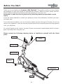
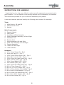
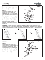
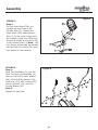
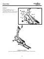
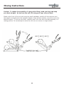
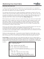
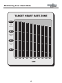
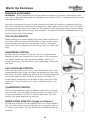
130e
Owner’s Manual
Ironman 130e Elliptical
Customer Service
1.800.750.IRON
1.800.750.4766
Ironman Fitness
4009 Distribution Drive
Suite 250
Garland, TX 75041
www.ironmanfitness.com
315-00089
Rev B 11/06
Table of Contents
Important Safety Information
3
Before You Start
4
Assembly
5-9
Console Instructions
10
Moving Instructions
11
Monitoring Your Heart Rate
12-13
Warm Up Exercises
14
Exploded View
15
Parts List
16
Warranty 17
Important Safety Information
WARNING! Before using this unit or starting any exercise program, consult your physician.
This is especially important for persons over the age of 35 and/or persons with pre-existing
health problems. The manufacturer or distributor assumes no responsibility for personal injury
or property damage sustained by or through the use of this product.
WARNING! To reduce the risk of electrical shock, burns, fire, or other possible injuries to the
user, it is important to review this manual and the following precautions before operation.
SAFETY PRECAUTIONS AND TIPS
1. It is the owner's responsibility to ensure that all users of this unit have read the Owner's
Manual and are familiar with warnings and safety precautions.
2. This unit has a user maximum capacity of 250 pounds.
3. The unit should only be used on a level surface and is intended for indoor use only. The unit
should not be placed in a garage, patio. Ironman Fitness recommends a mat be placed under
the unit to protect floor or carpet and for easier cleaning.
4. Wear comfortable, good-quality walking or running shoes and appropriate clothing. Do not
use the unit with bare feet, sandals, socks or stockings.
5. Always examine your unit before using to ensure all parts are in working order.
6. Allow the unit to fully stop before dismounting.
7. Pets should never be allowed near the unit.
8. Do not leave children unsupervised near or on the unit.
9. Never operate the unit where oxygen is being administered, or where aerosol products are
being used.
10. For safety and to prevent damage to your unit, no more than one person should use the
unit at a time.
11. Service to your unit should only be performed by an authorized service representative,
unless authorized and/or instructed by the manufacturer.
12. Failure to follow these instructions will void the unit warranty.
Before You Start
Thank you for purchasing the Ironman 130e Elliptical! This quality product you have chosen
was designed to meet your needs for cardiovascular exercise. Before you start, please read the
Owner's Manual and become familiar with the operation of your new unit.
Remember to take the time to perform the stretching exercises provided to avoid
injury.
If you are taking medication, consult your physician to see if the medication will affect your exercise heart rate.
If you have heart problems, you are not active, and/or are over the age of 35 years, do not use
the pre-set programs or start an exercise program without first contacting and receiving approval
from your physician.
Do not spill liquids on the console. Ironman Fitness recommends a sealed water bottle for beverages consumed while using the unit.
Please review the following drawing below to familiarize yourself with the listed
parts.
CONSOLE
HANDLEBAR W/
PULSE
TENSION KNOB
MAIN FRAME
TRANSPORT
WHEELS
EXTRUSIONS
PEDAL
Assembly
INSTRUCTIONS FOR ASSEMBLY:
Unpack the box in a clear area. Check to make sure all components are present and in
good condition. Do not dispose of the packing material until the assembly is completed.
Tools have been provided for you to use when assembling this product.
Locate the hardware pack and identify the following parts required for assembly.
Tools:
1. Allen Wrench, M6 and M8
2. Phillips Screw Driver
3. Wrench
Main Components:
1. Owner’s Manual
2. Main Frame
3. Handlebar w/Pulse Assembly
4. Upper Handlebar Assembly, Left and Right
5. Handlebar Post
6. Tension Knob
7. Sleeve Assembly Left and Right
8. Pedal Tube Assembly Left and Right
9. Console Assembly
10. Pedals Left and Right
11. Plastic Bellows
Hardware:
1. M5 x 10mm Screw (8) – Qty 4
2. Acorn Nut Cap (13) – Qty 2
3. M6 x 35mm Phillips Screw (28) – Qty 4
4. 6mm Black Locknut (33) – Qty 4
5. M8 x 90mm Hex Head Screw (46) – Qty 2
6. 8mm Locknut (thick) (49) – Qty 6
7. M8 x 19mm Washer (50) – Qty 8
8. M10 Locknut (thin) (52) – Qty 6
9. M8 x 15mm Hex Head Screw (63) – Qty 8
10. M10 x 57mm Screw (67) – Qty 2
11. M15.8 x 10 x 4.3T Spacer (68) – Qty 2
12. M10 x 23mm Washer (Silver) (69) – Qty 6
13. M8 x 18mm Curved Washer (72) Qty 6
14. M8 x 100mm Hex Head Screw (80) – Qty 4
15. M6 x 16mm Black Washer (85) – Qty 6
16. M6 x 45mm Screw (86) – Qty 6
Assembly
FIGURE 1
Step 1:
Using Two Carriage Bolts (46),
Cap Nuts (49), Hex Head
Screws (63) and Four Washers
(50), attach the Left and Right
Extrusions to Main Frame.
Step 2:
Attach Aluminum Extrusion
Plate (15) to the Left and Right
Extrusions using Four M8x95mm
Hex Head Screws (80), M8x19mm
Washers (50), and 8mm Locknuts
(49).
Figure 1
Figure 2
FIGURE 2
Step 1:
Using Three M6x45mm Screws
(86) and M6x16mm Washers (85)
attach Left Foot Pedal (16) to the
Left Pedal Tube Assembly (31).
Repeat for right side.
Assembly
FIGURE 3:
Step 1:
Slide the Plastic Bellow (14) onto the
Console Tube (2).
Step 2:
Connect the Console Cable (7) to
Sensor Wire (36). Connect the
Resistance Cable (73) to the Cable
from the Console Tube (Figure 3a-c).
Step 3:
Using Six M8x18mm Washers (72)
and M8x15mm Screws (63), Attach
the Console Tube (2) to the Main
Frame( 1). Slide the Plastic Bellows
down until it meets the Main.
Assembly. Secure using M4x16mm
Screw (19)
Figure 3
FIGURE 3a: Connect the Tension Knob to the Resistance Cable. Fit the Resistance Control
Cable into the slot of the Tension Knob. Pull the brass end of the Resistance Control Cable over
the lip of the Tension Knob Bracket. The connection should look like Figure 3c when completed.
3a
3c
3b
Figure 4
FIGURE 4
Step 1:
Pull the Hand Pulse Wires (25a)
coming from the Front Handlebar (5)
through the Console Tube. Attach
Front Handlbar (5) to Console Tube
using Two M8x45mm Screws (23),
Three M8x19mm Washers (50), Two
8mm Acorn Nuts (13), and One
M8x15mm Screw (63).
Assembly
Figure 5
FIGURE 5
Step 1:
Pull the Pulse Wires (25a) out
through the top of the of the
Console Tube (2). Connect the
Pulse Wires (25a) and Extension
Wire (7) to the wires coming from
the Console. Using Four M5x10mm
Screws (8) attach the Console (55)
to the Console Tube (2) Note: The
four Screws will already be installed
into the back of Console (55) when
you remove it from the box.
FIGURE 6:
Step 1:
Slide Left Handlebar (3) onto the
Stud. Connect Left Handlebar (3)
with one M10x19x2.0mm Washer
(69), M10x30 Black Washer (61),
Shaft Cap (12), M10 Locknut (52),
Acorn Cap Nuts (13), and M10
Curved Washer (87).
Step 2:
Repeat for right side.
Figure 6
Assembly
FIGURE 7
Attach Handlebars (3 & 4) to
Connecting Arm (30) using
M10x67mm Bolt (67), M10x21x1mm
Washer (20) and M10 Locknut (52)
Figure 7
CONGRATULATIONS!
You have completed Assembly of your New Ironman 130e Elliptical!
Console Instructions
CONSOLE BUTTONS:
MODE:
Press to change between TIME, SPEED, DISTANCE, CALORIE.
RESET:
Press to reset value stored for a specific function. Press and hold for four seconds to reset
console to factory settings.
SET:
When unit is idle, press to select desired function.
RECOVERY:
After workout is over, press to begin RECOVERY function.
GENERAL INFORMATION:
1. The console will shut off after it detects 4 minutes no activity.
2. Battery Specifications: Two 1.5V AA Batteries
3. If display is illegible or only partial segments appear, remove batteries, wait for 15 seconds
and reinstall batteries. If display is still illegible, you may need new batteries.
FUNCTIONS:
TIME:
This will count up from 00:00 up to 99:50 if you do not enter a preset time.
If you do enter a preset time the console will count down from the time you set to 0:00.
SPEED:
Displays the current exercise speed on the console screen.
DISTANCE:
This will count the accumulated distance during a workout.
If you enter a preset target the console will count from that distance set down to zero.
CALORIE:
This will count the accumulated calorie consumption during a workout.
If you enter a preset target the console will count from the amount set down to zero.
Note: This data is an estimate only and should be used as a comparison over several
exercise sessions.
PULSE:
This will display your current heart rate within 5 seconds of holding the handgrip.
Note: To obtain an accurate reading, hold the handgrips with both hands.
PULSE RECOVERY:
To monitor your improvement after each exercise the console is equipped with a special function known as RECOVERY. Before ending an exercise press the RECOVERY button. The console
will stop all function displays except TIME, which will count down from 00:60 to 00:00. Once
the time reaches 00:00 the console will show a Recovery Status with a grade of F1 to F6, F1
being the best and F6 being the worst. Press the PULSE RECOVERY button again to return to
the main display.
10
Moving Instructions
Caution! To reduce the possibility of injury while lifting, bend your legs and keep
your back straight. As you lean the unit, lift using your legs, not your back.
Stand at the front of the unit and using the small handlebar, carefully tilt the machine until
the weight is transferred to the transport wheels. Using extreme caution, move the unit to the
desired location. To set the unit down, carefully lower unit onto rear foot tube assembly in a
resting position. Do not attempt to move the unit over an uneven or rough surface.
11
Monitoring Your Heart Rate
Monitoring Your Heart Rate
To obtain the greatest cardiovascular benefits from your exercise workout, it is important to
work within your target heart rate zone. The American Heart Association (AHA) defines this target as 60%-75% percent of your maximum heart rate.
Your maximum heart rate may be roughly calculated by subtracting your age from 220. Your
maximum heart rate and aerobic capacity naturally decreases as you age. This may vary from
one person to another, but use this number to find your approximate effective target zone. For
example, the maximum heart rate for an average 40 year-old is 180 bpm. The target heart
rate zone is 60%-75% of 180 or 108-135 bpm. See Fitness Safety below.
Before beginning your workout, check your normal resting heart rate. Place your fingers lightly
against your neck, or against your wrist over the main artery. After finding your pulse, count
the number of beats in 10 seconds. Multiply the number of beats by six to determine your
pulse rate per minute. We recommend taking your heart rate at these times; at rest, after
warming up, during your workout and two minutes into your cool down, to accurately track
your progress as it relates to better fitness.
During your first several months of exercising, the AHA recommends aiming for the lower part
of the target heart rate zone-60%, then gradually progressing up to 75%.
According to the AHA, exercising above 75% of your maximum heart rate may be too strenuous unless you are in top physical condition. Exercising below 60% of your maximum will result
in minimal cardiovascular conditioning.
Check your pulse recovery rate – If your pulse is over 100 bpm five minutes after you stop
exercising, or if it’s higher than normal the morning after exercising, your exertion may have
been too strenuous for your current fitness level. Rest and reduce the intensity next time.
Fitness Safety The target heart rate chart indicates average rate zones for different ages. A
variety of different factors (including medication, emotional state, temperature and other conditions) can affect the target heart rate zone that is best for you. Your physician or health care
professional can help you determine the exercise intensity that is appropriate for your age and
condition.
(MHR) = Maximum Heart Rate
(THR) = Target Heart Rate
220 - age = maximum heart rate (MHZ)
MHZ x .60 = 60% of your maximum heart rate.
MHZ x .75 = 75% of your maximum heart rate.
For example, if you are 30 years old, your calculations will be as
follows:
220 - 30 = 190
190 x .60 = 114 (low end or 60% of MHZ)
190 x .75 = 142 (high end or 75% of MHZ)
30 year-old (THR) Target Heart Rate would be 114-142
See Heart Rate Table (on page 12) for additional calculations.
12
Monitoring Your Heart Rate
TARGET HEART RATE ZONE
100%
200
195
190
185
180
Serious
athletic
training range
85%
170
166
162
Cardiovascular
conditioning
range
75%
150
146
143
157
139
153
135
Fat burning
range
60%
120
20
117
25
114
30
111
35
108
40
175
149
131
105
45
AGE
13
170
145
128
165
140
124
160
136
120
102
99
96
50
55
60
155
132
116
93
65
Warm Up Exercises
EXERCISE GUIDELINES
WARNING! Before beginning this or any exercise program, you should consult your physician. This is especially important for individuals over the age of 35 or individuals with pre-existing health problems.
Warming up prepares the body for the exercise by increasing circulation, supplying more oxygen to the muscles and raising body temperature. Begin each workout with 5 to 10 minutes of
stretching and light exercise to warm up. The photos on this page show several forms of basic
stretching you may perform before your workouts. In order to achieve an adequate warm-up,
perform each stretch three times.
TOE TOUCH STRETCH
Stand bending your knees slightly and slowly bend forward from
your hips. Allow your back and shoulders to relax as you reach
down toward your toes as far as possible. Hold for 15 counts,
then relax. This will stretch your hamstrings, back of knees, and
back.
HAMSTRING STRETCH
Sit with one leg extended. Bring the sole of the opposite foot
toward you and rest it against the inner thigh of your extended
leg. Reach toward your toes as far as possible. Hold for 15
counts, then relax. This will stretch your hamstrings, lower back,
and groin.
CALF/ACHILLES STRETCH
With one leg in front of the other, reach forward and place your
hands against a wall. Keep your back leg straight and your back
foot flat on the floor. Bend your front leg, lean forward and move
your hips toward the wall. Hold for 15 counts, then relax. To
cause further stretching of the Achilles tendon, bend your back
leg as well. This will stretch your calves, Achilles tendons, and
ankles.
QUADRICEPS STRETCH
With one hand against a wall for balance, reach back and grasp
one foot with your other hand. Bring your heel as close to your
buttocks as possible. Hold for 15 counts, then relax. This will
stretch your quadriceps and hip muscles.
INNER THIGH STRETCH (Image not Shown)
Sit with the soles of your feet together and your knees outward.
Pull your feet toward your groin area as far as possible. Hold for
15 counts, then relax. This will stretch your quadriceps and hip
muscles.
14
Exploded View
15
Parts List
130e Parts List Rev B
Ref #
1
2
3
4
5
6
7
8
9
10
11
12
13
14
15
16
17
18
19
20
21
22
23
24
25
25a
26
27
28
29
30
31
32
33
34
35
36
37
38
39
40
41
42
43
44
45
46
Part #
323-00452
323-00453
323-00478
323-00479
319-00354
311-00090
313-00378
302-00443
311-00084
306-00698
306-00699
306-00716
302-01233
306-00700
319-00257
306-00712
306-00673
319-00260
302-01192
302-01363
302-01362
302-00402
302-01371
302-01201
310-00201
313-00379
311-00088
311-00089
302-01370
331-00099
319-00356
323-00454
323-00455
331-00100
302-00417
302-00415
313-00370
306-00713
302-00859
302-01367
302-01195
302-00399
302-00401
302-01197
319-00261
323-00456
302-00189
Description
MAIN FRAME, 130e
CONSOLE TUBE, 130E
HANDLE, LEFT FOAM 130E
HANDLE, RIGHT FOAM 130E
HANDLEBAR, FRONT 130E
PULLEY, 130E
EXTENSION WIRE, 130E
M5 X10MM SCREW 220E/240E/240R/240U/640R/
MAG BRAKE, 130E
TRANSPORTATION WHEEL, 130E/U/R
PLASTIC RING, 130E/U/R
SHAFT CAP 130E
CAP NUT, 8MM
COLLAR, CONSOLE TUBE 130E/R
ALUMINUM EXTRUSION PLATE, 130E
FOOT PEDAL, 130E
SQUARE FOOT CAP, 40X80
FRONT ROLLER, 130E
TP M4 X 16 MM SCREW
WASHER, M10X21X1
SCREW, 3/8 "X40MM HEX
M10X19x2.0 MM WASHER,220E/240E/240R/240U
SCREW, M8X45MM HEX HEAD
7/8" x24 MM HEX CAP NUT
GRIP, HAND PULSE 130E
HAND PULSE WIRE, 130E
CRANK, LEFT 130E
CRANK, RIGHT 130E
SLOTTED BEARING NUT, 130E/R/U
BEARING SET (12 PCS), 130E/R/U
CONNECTING ARM, 130E
FRAME, LEFT FOOT 130E
FRAME, RIGHT FOOT 130E
BEARING CUP, 130E/R/U
TP M5 X50MM SCREW
TP 3X8MM SCREW
SENSOR WIRE W/WIRE, 130U/R/E
SLEEVE, HANDLEBAR 130E
32MM BUSHING
MAGNET, 130E/U/R
EYEBOLT 6 X 40MM
ADJUSTMENT CHANNEL ALL MACRO BIKES
M6 HEX NUT(ZINC)
CAP NUT, 3/8" X 26MM
PU ROLLER, 130E
LEFT ALUMINUM EXTRUSION, 130E
SCREW, M8X90MM
Qty
1
1
1
1
1
1
1
4
1
2
2
2
2
1
1
2
4
2
5
4
2
2
2
4
2
2
1
1
1
2
2
1
1
2
6
2
1
2
4
1
3
2
2
2
2
2
2
Ref #
47
48
49
50
51
52
53
54
55
56
57
58
59
60
61
62
63
64
65
66
67
68
69
70
71
72
73
74
75
76
77
78
79
80
81
82
83
84
85
86
87
88
89
90
91
92
16
Part #
302-01198
311-00086
302-01212
302-00449
302-00487
302-01260
302-01368
302-01199
307-00138
302-01366
302-00416
302-01365
304-00023
310-00200
302-00441
331-00093
302-00411
319-00239
302-01249
302-01408
302-01409
306-00735
302-00402
305-00189
305-00190
302-01364
313-00379
302-00922
302-00769
319-00357
331-00047
306-00736
302-01407
302-01406
302-01211
302-01210
306-00372
306-00651
302-00444
302-00445
302-00435
306-00714
306-00715
307-00718
302-01194
302-01361
Description
HEX HEAD SCREW, M8 X 20MM
IDLER PULLEY, 130E/R/U
M8 LOCKNUT (THICK), HT640U
M8X19MM WASHER BLACK U/R/E 220/240/250
M8 X 38MM BUTTON HEAD SCREW TRI-6.0R#53A
BLACK LOCKNUT, 10MM (THIN)
SPRING, 130E/R/U
M8X12.5X10L SPACER
CONSOLE, 130E/U/R
CRANK WASHER, 130E/R/U
TP M4 X 12MM SCREW
CRANK NUT, 130E/R/U
BELT, 130R/130U
TENSION KNOB ASSEMBLY, 130E
M17 X22MM WASHER 220E/240E/240R
PRECISE BEARING, 6000
M8 X15 HEX HEAD SCREW
BELT TENSION BRACKET, 130E/U/R
SCREW, M10X47MM
SCREW, HX HD M8X63MM
SCREW, HEX HD M10X67MM
BUSHING, PLASTIC 10X26X8.0T
M10X19x2.0 MM WASHER,220E/240E/240R/240U
HOUSING, BOTTOM LEFT 130E
HOUSING, BOTTOM RIGHT 130E
WASHER, M8X18MM CURVED
TENSION WIRE, 130E
6X65 EYEBOLT#37A
6MM HEX NUT#47
JOINTER, 130E
BEARING PRECISE, 6202Z,220E/240E/250E
BUSHING, PLASTIC 17X35X10.0T
WASHER, M26X37X2.0 (BLACK)
SCREW, HEX HD M8X95MM
M8 LOCKNUT (THIN), HT640U
M5X50MM PHILLIP SCREW
1 1/4" BALL PLUG 220R/240R/240U/640R/520
SPACER, M13.95X10X8L
WASHER, M6X16MM (BLACK)
M6 X45 MM HEX HEAD SCREW, 220E/240E/640R
M10 CURVED WASHER 220E/240E/520e
CAP, LEFT ROLLER 130E
CAP, RIGHT ROLLER 130E
CRANK CAP, 130E
CAP NUT M10 X P1.25R
WASHER, 38X24X1.5T
Qty
1
1
7
14
1
10
1
1
1
1
8
1
1
1
4
8
9
1
2
2
2
4
6
1
1
6
1
1
2
2
4
4
2
1
3
1
4
2
6
6
6
2
2
2
2
1
Warranty Information
IRONMAN FITNESS 130e LIMITED WARRANTY
Residential Warranty
Frame: Lifetime
Parts: 1 Year
Labor: None
This Limited Warranty applies in the United States and Canada to products manufactured or distributed by Ironman Fitness
(“Ironman”) under the Ironman brand name. The warranty period to the original purchaser is listed above in the table.
Ironman warrants that the Product you have purchased for use from Ironman or from an authorized Ironman reseller is free from
defects in materials or workmanship under normal use during the warranty period. Your sales receipt, showing the date of purchase
of the Product, is your proof of purchase. This warranty only extends to you, the original purchaser. It is not transferable to anyone
who subsequently purchases the Product from you. It excludes expendable parts (wear items). Wear items pertain to components
that might need to be replaced due to normal wear and tear. These items vary per product but will include pedal straps, seats, grips,
chains, bottom bracket assemblies, pads, etc. Please contact an Ironman customer service representative for specifics on wear
items. This Limited Warranty becomes VALID ONLY if the product is purchased through an Ironman Fitness authorized dealer
unless otherwise authorized by Ironman Fitness in writing.
During the warranty period Ironman will repair or replace (at Ironman’s option) the product if it becomes defective, malfunctions,
or otherwise fails to conform with this Limited Warranty under normal use. In repairing the Product, Ironman may replace defective parts, or at the option of Ironman, serviceable used parts that are equivalent to new parts in performance. All exchanged parts
and Products replaced under this warranty will become the property of Ironman. Ironman reserves the right to change manufacturers of any part to cover any existing warranty.
This warranty DOES NOT COVER shipping charges, export taxes, custom duties and taxes, or any other charges associated with
transportation of the parts or Product.
To obtain warranty service, you must contact an Ironman authorized retailer, service technician or Ironman Fitness at our phone
number located in this manual. Any parts determined to be defective must be returned to Ironman to obtain warranty service. You
must prepay any shipping charges, export taxes, custom duties and taxes, or any other charges associated with transportation of the
parts or Product. In addition, you are responsible for insuring any parts or Product shipped or returned. You assume the risk of loss
during shipment. You must present Ironman with proof-of-purchase documents (including the date of purchase). Any evidence of
alteration, erasing or forgery of proof-of-purchase documents will be cause to void this Limited Warranty.
This warranty does not extend to any product not purchased from Ironman or from an authorized Ironman reseller. This Limited
Warranty does not extend to any Product that has been damaged or rendered defective; (a) as a result of accident, misuse, or abuse;
(b) by the use of parts not manufactured or sold by Ironman; (c) by modification of the Product or normal wear and tear; (d) operation on incorrect power supplies; or (e) as a result of service by anyone other than Ironman, or an authorized Ironman warranty
service provider. Product on which the serial number has been defaced or removed is not eligible for warranty service. Should any
Product submitted for warranty service be found ineligible, an estimate of repair cost will be furnished and the repair will be made
if requested by you upon Ironman’s receipt of payment or acceptable arrangements for payment.
EXCEPT AS EXPRESSLY SET FORTH IN THIS WARRANTY, IRONMAN MAKES NO OTHER WARRANTIES,
EXPRESSED OR IMPLIED, INCLUDING ANY IMPLIED WARRANTIES OF MER CHANT ABILITY AND FITNESS FOR
A PARTICULAR PURPOSE. IRONMAN EXPRESSLY DISCLAIMS ALL WARRANTIES NOT STATED IN THIS LIMITED
WARRANTY. ANY IMPLIED WARRANTIES THAT MAY BE IMPOSED BY LAW ARE LIMITED TO THE TERMS OF
THIS LIMITED WARRANTY. NEITHER IRONMAN NOR ANY OF ITS AFFILIATES SHALL BE RESPONSIBLE FOR
INCIDENTAL OR CONSEQUENTIAL DAMAGES. SOME STATES DO NOT ALLOW LIMITATIONS ON HOW LONG
AN IMPLIED WARRANTY LASTS OR THE EXCLUSION OR LIMITATION OF INCIDENTAL OR CONSEQUENTIAL
DAMAGES, SO THE ABOVE LIMITATIONS OR EXCLUSION MAY NOT APPLY TO YOU. This Limited Warranty gives
you specific legal rights and you may also have other rights that may vary from state to state. This is the only expressed warranty
applicable to Ironman-branded products. Ironman neither assumes nor authorizes anyone to assume for it any other express warranty.
PLEASE SEND IN THE ATTACHED WARRANTY CARD WITHIN TEN (10) DAYS OF PURCHASE TO
REGISTER YOUR UNIT WITH IRONMAN FITNESS.
17
Customer Service
1.800.750.IRON
1.800.750.4766
Ironman Fitness
4009 Distribution Drive
Suite 250
Garland, TX 75041
www.ironmanfitness.com
Ironman and M-dot are registered trademarks of the World Triathlon Corp., used here by permission.