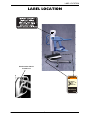
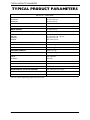
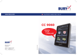
1
Owner’s Operator and Maintenance Manual
1900/1900S Bath Lift
DEALER: This manual MUST be given to
the user of the patient lift.
USER: BEFORE using this patient lift, read
this manual and save for future reference.
For more information regarding Invacare
products, parts, and services, please visit
www.invacare-ccg.com or call 800.668.2337
WARNING
DO NOT use this product or any available optional equipment without first
completely reading and understanding these instructions and any additional
instructional material such as owner’s manuals, service manuals or instruction
sheets supplied with this product or optional equipment. If you are unable to
understand the warnings, cautions or instructions, contact a healthcare
professional, dealer or technical personnel before attempting to use this
equipment - otherwise, injury or damage may occur.
ACCESSORIES WARNING
Invacare products are specifically designed and manufactured for use in conjunction
with Invacare accessories. Accessories designed by other manufacturers have not
been tested by Invacare and are not recommended for use with Invacare products.
For further information on this product, please call the following:
Customer Service ‐ 1‐800‐668‐2337
Technical Support ‐ 1‐866‐616‐2631
NOTE: Updated versions of this manual are available on www.invacare‐ccg.com.
1900/1900S Bath Lift
2
Part No. 1148113
TABLE OF CONTENTS
TABLE OF CONTENTS
SPECIAL NOTES ................................................................................ 4
LABEL LOCATION ............................................................................ 5
TYPICAL PRODUCT PARAMETERS .................................................... 6
SECTION 1—GENERAL GUIDELINES ................................................... 7
Operating the Lift .......................................................................................................................................7
Lifting/Transferring .....................................................................................................................................7
Performing Maintenance ...........................................................................................................................8
Electrical - Grounding Instructions ........................................................................................................8
Pinch Points..................................................................................................................................................8
SECTION 2—OPERATING THE BATH LIFT .......................................... 9
Transferring into/out of the Bathing Unit .............................................................................................9
Raising/Lowering the Bath Lift ...............................................................................................................11
Using the Scale (Model 1900S ONLY) ................................................................................................11
Emergency Lowering ...............................................................................................................................12
Disinfecting the Lift ..................................................................................................................................12
Mounting the Battery Charger ..............................................................................................................13
Charging the Battery ...........................................................................................................................14
Removing/Installing the Safety Strap.....................................................................................................15
Using the Shoulder Strap ........................................................................................................................16
SECTION 3— MAINTENANCE AND TROUBLESHOOTING .................. 17
Safety Inspection Checklists...................................................................................................................17
Inspect/Adjust Initially and Monthly.................................................................................................17
Care and Maintenance of Bath Lift .......................................................................................................18
Detecting Wear and Damage ................................................................................................................18
Cleaning the Lift........................................................................................................................................18
Maintenance Procedures.........................................................................................................................19
Adjusting Arm Angle and Tension ...................................................................................................19
Inspecting/Tightening the Seat ..........................................................................................................20
Inspecting and Adjusting the Lift Column ......................................................................................20
Calibrate the 1900 Scale .........................................................................................................................22
Troubleshooting........................................................................................................................................23
LIMITED WARRANTY ..................................................................... 24
Part No. 1148113
3
1900/1900S Bath Lift
SPECIAL NOTES
SPECIAL NOTES
Signal words are used in this manual and apply to hazards or unsafe practices which could result in personal injury or property damage. Refer to the table below for definitions of the signal words.
SIGNAL WORD
MEANING
DANGER
Danger indicates an imminently hazardous situation which, if not avoided, will
result in death or serious injury.
WARNING
Warning indicates a potentially hazardous situation which, if not avoided,
could result in death or serious injury.
CAUTION
Caution indicates a potentially hazardous situation which, if not avoided, may
result in property damage or minor injury or both.
NOTICE
THE INFORMATION CONTAINED IN THIS DOCUMENT IS SUBJECT TO
CHANGE WITHOUT NOTICE.
RADIO FREQUENCY INTERFERENCE
Most electronic equipment is influenced by Radio Frequency Interference (RFI).
CAUTION should be exercised with regard to the use of portable communication
equipment in the area around such equipment. If RFI causes erratic behavior, PUSH
the Red Power Switch OFF IMMEDIATELY. DO NOT turn the Power Switch ON
while transmission is in progress.
MAINTENANCE
Maintenance MUST be performed ONLY by qualified personnel.
1900/1900S Bath Lift
4
Part No. 1148113
LABEL LOCATION
LABEL LOCATION
Serial number label is
located here
WARNING
Pinch Point.
1079203
Part No. 1148113
5
1900/1900S Bath Lift
TYPICAL PRODUCT PARAMETERS
TYPICAL PRODUCT PARAMETERS
BATH LIFT 1900/1900S
SEAT HEIGHT
MAXIMUM:
MINIMUM:
41 inches (104 cm)
18 inches (45 cm)
SEAT WIDTH
16.5 inches (42 cm)
SEAT DEPTH
16 inches (40 cm)
BACK HEIGHT
21 inches (53 cm)
BASE HEIGHT (CLEARANCE):
5 inches (12 cm)
OVERALL DIMENSIONS
HEIGHT:
LENGTH:
WIDTH:
50 - 74 inches (127 - 187 cm)
47 inches (119 cm)
28.5 inches (72 cm)
CASTER SIZE (FRONT/REAR):
3 inches / 5 inches (7 cm / 12cm)
WEIGHT CAPACITY:
350 lbs (158 kg)
WEIGHT:
200 lbs (90 kg)
SHIPPING WEIGHT:
245 lbs (111 kg)
BATTERY:
24V DC Rechargeable
CHARGER
INPUT:
OUTPUT:
100 - 240 VAC
29.5 VDC
CHARGING TIME:
6 Hours Maximum
AUDIO LOW BATTERY ALARM:
Yes
MOTOR SAFETY DEVICES:
Anti-Entrapment
APPROXIMATE LIFTS PER CHARGE:
100 - 200 Cycles per Charge*
WARRANTY (ELECTRIC/ELECTRONICS):
1 Year
EMERGENCY STOP BUTTON:
Yes
*NOTE: Varies depending upon load and stroke.
1900/1900S Bath Lift
6
Part No. 1148113
SECTION 1—GENERAL GUIDELINES
SECTION 1—GENERAL GUIDELINES
WARNING
SECTION 1 - GENERAL GUIDELINES contains important information for the safe
operation and use of this product.
Operating the Lift
Check all parts for shipping damage before using. In case of damage, DO NOT use the equipment. Contact the dealer or customer service for further instructions.
DO NOT attempt any transfer without approval of the resident’s physician, nurse or medical assistant. Thoroughly read the instructions in this owner’s manual, observe a trained team of experts perform the lifting procedures and then perform the entire lift procedure several times with proper supervision and a capable individual acting as a resident.
Use common sense in all lifts. Special care MUST be taken with people with disabilities who cannot fully cooperate while being transferred. Although Invacare recommends that two assistants be used for all lifting and transferring procedures, our equipment will permit proper operation by one assistant. The use of one assistant is based on the evaluation of the health care professional for each individual case.
Make sure there is an audible click when mounting battery on the battery charger to confirm proper mounting. Otherwise, injury or damage may occur.
DO NOT exceed maximum weight limitation of the lift. The weight limitation for the 1900 and 1900S bath lift is 350 lbs.
ALWAYS keep hands and fingers clear of moving parts to avoid injury.
Lifting/Transferring
Invacare recommends the use of the safety strap and shoulder harness when using the bath lift. ALWAYS adjust the safety strap and shoulder harness for safety and comfort before transport.
During transfer, raise the seat so the resident’s feet are suspended from the floor. DO NOT roll caster base over objects such as carpet, raised carpet bindings, door frames, or any uneven surfaces or obstacles that would create an imbalance of the lift and could cause the lift to tip over. Wheelchair wheel locks MUST be in a locked position before transferring the resident into the wheelchair for transport.
Part No. 1148113
7
1900/1900S Bath Lift
SECTION 1—GENERAL GUIDELINES
Performing Maintenance
Refer to Maintenance and Troubleshooting on page 17 for a maintenance schedule and procedures.
Regular maintenance of lifts and accessories is necessary to assure proper operation.
Casters and axle bolts require inspections every six months to check for tightness, wear, debris (such as hair and dirt) and that they roll free.
After the first twelve months of operation, inspect all glides, rollers, and fasteners for wear. If the metal is worn, the parts MUST be replaced. Make this inspection every six months thereafter.
The electric motor is sealed at the factory and if service is required, the motor unit MUST be returned to the factory for repair. DO NOT attempt to open the motor or obtain local service as this will VOID the warranty and may result in damage and a costly repair. Consult your dealer or Invacare for further information.
Electrical - Grounding Instructions
DO NOT, under any circumstances, cut or remove the round grounding prong from any plug. Some devices are equipped with three‐prong (grounding) plugs for protection against possible shock hazards. Where a two‐prong wall receptacle is encountered, it is the personal responsibility and obligation of the customer to contact a qualified electrician and have the two‐prong receptacle replaced with a properly grounded three‐
prong wall receptacle in accordance with the National Electrical Code. If you must use an extension cord, use only a three‐wire extension cord having the same or higher electrical rating as the device being connected. In addition, Invacare has placed RED/ORANGE WARNING TAGS on some equipment. DO NOT remove these tags. Carefully read battery/battery charger information prior to installing, servicing or operating your lift.
Pinch Points
WARNING
Pinch points exist at base of lift. Be careful, injury could occur.
Caster
Pinch
Points
Lift
Base
Casters
Caster
FIGURE 1.1 Pinch Points
1900/1900S Bath Lift
8
Part No. 1148113
SECTION 2—OPERATING THE BATH LIFT
SECTION 2—OPERATING THE
BATH LIFT
WARNING
DO NOT attempt any transfer of a resident without approval of the resident's
physician, nurse, or medical assistant. Thoroughly read the instructions in this
owner's manual, observe a trained team of experts performing the lifting
procedures and then perform the entire lift procedure several times with proper
supervision and a capable individual acting as a resident.
Adjustments for safety and comfort should be made before moving the resident.
Lock the rear casters of the bath lift when transferring an individual onto the seat.
Locking the rear casters will stabilize the lift and help prevent it from shifting during
transfer.
Each facility and each resident will require a unique set of instructions and
procedures to follow for each bath. Check with your supervisor and the resident’s
chart for the proper procedures to follow.
Review and practice the operation with able an bodied assistant before attempting
with a resident.
NOTE: Invacare recommends that two assistants be used for all lifting preparation and transferring to/from procedures; however, the bath lift can be operated with one assistant. The use of one assistant is based on the evaluation of the health care professional for each individual case.
Transferring into/out of the Bathing Unit
NOTE: For this procedure, refer to FIGURE 2.1 and FIGURE 2.2 on page 10.
NOTE: To transfer out of the bathing unit, reverse this procedure.
NOTE: In some cases, the resident may need to be weighed. Refer to Using the Scale (Model 1900S ONLY) on page 11.
1. Bring the lift into position with the resident.
NOTE: The seat may be lowered to its lowest position for a wheelchair transfer, or to a convenient height for a bed to wheelchair transfer, etc. Use the transfer methods prescribed by your facility and the needs of the resident.
2. Lock the two rear locking casters on the lift by pressing down on the locking pedal with your foot. Refer to FIGURE 2.1.
3. Swing one or both armrests up and back.
4. Transfer the resident.
5. Slowly bring the arm rests down in front of the resident.
Part No. 1148113
FIGURE 2.1 Transferring into/out of the
Bathing Unit
9
1900/1900S Bath Lift
SECTION 2—OPERATING THE BATH LIFT
WARNING
Follow the facilities procedure for each individual.
Invacare recommends the use of the safety strap and shoulder harness when using
the bath lift. ALWAYS adjust the safety strap and shoulder harness for safety and
comfort before transferring the resident onto the chair.
The safety strap should be used when lifting or transferring. Otherwise, the resident
may fall from the seat.
6. Raise the lift seat by pressing the Up arrow on the hand pendant to ensure the resident’s feet are off the floor.
7. Unlock the wheels and transfer the resident to the bathing area.
8. Open the door of the bathing unit.
9. Adjust the height of the lift seat so it is slightly higher than the actual seat of the tub.
10. Slowly begin to bring the resident and seat into the open tub (Detail “A”).
NOTE: Approach at an angle roughly 45 degrees to the tub.
11. Place the resident’s feet in the foot well of the tub.
12. Continue guiding the resident and the lift chair into the tub (Detail “B”).
13. Gradually rotate the lift until the support column and push handles are behind and outside the rear rim of the tub and the resident and lift chair are inside the tub (Detail “C”).
Support Column
Push
Handles
DETAIL “A” - BRINGING
DETAIL “B”- GUIDING
DETAIL “C” - PLACING
FIGURE 2.2 Transferring into/out of the Bathing Unit
14. Once the resident and chair are completely and safely inside the tub, use the hand pendant to lower the lift chair until it is just above the seat of the tub but not touching. Refer to Raising/Lowering the Bath Lift on page 11.
WARNING
Make sure arms and legs are out of the way of the door to avoid pinching either the
resident’s or attendant’s limbs in the door.
CAUTION
Fully Raised
Position
Make sure the locking handle of the tub
is in the fully raised position when the
door is being closed.
1900/1900S Bath Lift
10
Part No. 1148113
SECTION 2—OPERATING THE BATH LIFT
15. Lock the two rear locking casters on the lift by pressing down on the locking pedal with your foot. Refer to FIGURE 2.1.
16. Lock the bathing unit door. Refer to the bathing unit’s owner’s manual.
Raising/Lowering the Bath Lift
NOTE: For this procedure, refer to FIGURE 2.3.
To raise the bath lift, press the up arrow button on the hand pendant.
To lower the bath lift, press the down arrow button on the hand pendant.
FIGURE 2.3 Raising/Lowering the Bath Lift
Using the Scale (Model 1900S ONLY)
NOTE: For this procedure, refer to FIGURE 2.4.
1. With the seat empty and arms lowered, turn on the scale by touching the “on” button on the face of the scale.
2. Press the “ZERO” button on the face of the scale. NOTE: The digital readout shows 0.0.
3. Using the “UNITS” button, select either kilograms or pounds.
4. Transfer the resident on the seat of the lift and lower the arms.
5. Raise the resident. NOTE: It is only necessary to raise the resident until his/her feet are off the floor and not touching the legs of the lift.
6. Press the “LOCK” key
7. Read and record the weight of the resident on the readout of the scale. FIGURE 2.4 Using the Scale (Model 1900S
ONLY)
Emergency Stop
Control Box
RED Emergency Stop Button
NOTE: For this procedure, refer to FIGURE 2.5.
• Press the RED emergency stop button on the control box to stop the lift seat and resident from raising or lowering.
• To disengage, rotate the RED emergency stop button CLOCKWISE until it pops out.
Press to Stop
Lift Seat
Rotate CLOCKWISE to
Disengage Emergency Stop
FIGURE 2.5 Emergency Stop
Part No. 1148113
11
1900/1900S Bath Lift
SECTION 2—OPERATING THE BATH LIFT
Emergency Lowering
NOTE: For this procedure, refer to FIGURE 2.6.
In the event of a handset or control box failure, the lift can still be lowered by using one of the three following methods, depending on reason the lift has not lowered:
• If the battery is fine, but pendant is not or control box has failed and the lift needs to be lowered ‐ Press the tip of a ballpoint pen into the small opening below and to the right of the stop button on the control box (Detail “A”).
• If the battery has failed and the lift needs to be lowered ‐ Pull down the red tag located above the battery near the push handle on the actuator column (Detail “B”). NOTE: Weight or force MUST be exerted upon the seat in order for this procedure to work.
DETAIL “B”
DETAIL “A”
Pull Down Red Tag
for Emergency
Lowering
Control Box
Actuator
Column
Press Ballpoint Pen Tip Here
for Emergency Lowering
FIGURE 2.6 Emergency Lowering
Disinfecting the Lift
NOTE: For this procedure, refer to FIGURE 2.7 on page 13.
WARNING
The seat and arms of the lift MUST be disinfected after each use with a bath.
ALWAYS wear protective gloves and eye protection when working concentrated
chemical disinfectants.
1. Prepare a working solution of Invacare disinfectant by doing the following:
A. Mix concentrated disinfectant with water to a dilution ration of half‐an‐ounce of disinfectant per one gallon of water.
B. Transfer the diluted disinfectant into a labeled spray bottle.
2. Position the bath lift into the tub. Refer to STEPS 13 to 16 in Transferring into/out of the Bathing Unit on page 9.
3. Spray both sides of the seat surface, the safety strap, the shoulder strap, and the arm rests of the lift. Refer to Detail “A” of FIGURE 2.7.
4. Gently wipe the push handles, scale, hand pendant, and any other surfaces that were handled during the transport and bathing of the resident with a wash cloth containing the diluted disinfectant. Refer to Detail “B” of FIGURE 2.7.
5. Let the disinfectant sit for ten minutes.
1900/1900S Bath Lift
12
Part No. 1148113
SECTION 2—OPERATING THE BATH LIFT
6. After ten minutes, rinse the seat surface, safety strap, shoulder strap, arm rests, and any other non‐electronic surface with the shower wand of the bath. Refer to the individual bathing unit’s owner’s manual for using the shower wand.
CAUTION
DO NOT spray the push handles, scale, or hand pendant with water. Sprayed water
may damage the electronic components of the lift.
7. Lightly wipe the push handles, scale, and hand pendant with a damp cloth.
8. Dry all surfaces with a clean towel.
9. Remove the bath lift from the tub. Reverse STEPS 13 to 16 in Transferring into/out of the Bathing Unit on page 9.
DETAIL “A” - NON ELECTRONIC SURFACES
DETAIL “B” - ELECTRONIC SURFACES
Hand
Pendant
Arm Rests
Seat
Surface
Scale
Push
Handles
Safety Strap
NOTE: Shoulder Strap not shown.
Base
FIGURE 2.7 Disinfecting the Lift
Mounting the Battery Charger
NOTE: For this procedure, refer to FIGURE 2.8.
NOTE: Refer to your local regulations concerning proper mounting procedures.
1. Place the battery charger with mounting bracket on the wall at the desired position.
2. With a pencil, mark the middle hole position.
3. Measure down 6½ inches from the pencil mark and drill one mounting hole.
4. Install the bottom mounting screw until there is an approximate 1/8‐inch gap between the screw head and the wall.
5. Install the battery charger with mounting bracket onto the bottom mounting screw.
6. Drill the remaining two mounting holes.
7. Install the two remaining mounting screws through the mounting bracket and into the wall. Tighten securely.
8. Plug the battery charger into the wall electrical outlet.
NOTE: The On LED should illuminate.
Part No. 1148113
13
1900/1900S Bath Lift
SECTION 2—OPERATING THE BATH LIFT
Battery Charger with
Mounting Bracket
(STEP 5)
Mounting Bracket
(STEP 6)
BOTTOM
Mounting Screw
(STEP 4)
Mounting Screws
(STEP 7)
FIGURE 2.8 Mounting the Battery Charger
Charging the Battery
NOTE: For this procedure, refer to FIGURE 2.9.
NOTE: Invacare recommends the battery be recharged daily to prolong battery life. NOTE: An audible alarm will sound (horn will beep) when battery is low.
1. Lift up on the handle on the back of the battery (Detail “A”).
2. Lift the battery up and out from the control box.
NOTE: The battery is Emergency Pull Pin
shown being removed from and installed into a control box. Removing and installing a battery into a battery charger is done the same way.
WARNING
Make sure there is an audible click when
mounting battery either on the battery
charger or the control box to confirm
proper mounting. Otherwise, injury or
damage may occur.
DETAIL “A”
3. Place the battery on the battery charger (Detail “B”).
Handle
NOTE: There will be an audible click.
NOTE: The charge LED will illuminate. When charging is complete, the charge LED will stop illuminating.
Battery
Battery
Control Box
DETAIL “B”
NOTE: A battery needing to be fully recharged will take approximately four hours.
Battery
DETAIL “C”
Battery DETAIL “D”
4. Lift up on the handle on the back of the battery (Detail “A”).
5. Lift the battery up and out away from the battery charger.
6. Reinstall the battery onto the control box of the lift (Detail “B”).
7. Push the battery into the lift housing and rock slightly until it locks into place (Detail “C”).
Control Box
NOTE: There will be an audible click when the battery locks into place (Detail “D”).
1900/1900S Bath Lift
Audible
Click
Control
Box
FIGURE 2.9 Charging the Battery
14
Part No. 1148113
SECTION 2—OPERATING THE BATH LIFT
Removing/Installing the Safety Strap
WARNING
DO NOT put the safety strap in the dryer. The high heat will melt the belt’s material.
NOTE: For this procedure, refer to FIGURE 2.10.
NOTE: The safety strap MUST be washed and disinfected after each use. 1. Unbuckle the safety strap by pulling up the hook‐and‐loop strip on the buckle.
2. Pull the hook‐and‐loop strip through the buckle (Detail “A”).
3. Remove the safety strap from the chair.
4. Repeat STEPS 1 to 3 for the other side.
5. Wrap the new safety strap around the lift frame.
6. Insert the hook‐and‐loop strip through the buckle and secure it to the chair frame (Detail “B”).
7. Repeat STEPS 5 and 6 for the other side.
Chair Frame
Safety Strap
Buckle
DETAIL “A”
Chair Frame
Safety Strap
Hook-and-Loop Strip
Buckle
DETAIL “B”
Hook-and-Loop Strip
FIGURE 2.10 Removing/Installing the Safety Strap
Installing/Removing the
Shoulder Strap
Shoulder
Strap
NOTE: For this procedure, refer to FIGURE 2.11.
Chair
NOTE: To remove the shoulder strap, reverse this procedure.
Hookand-Loop
Strip
1. Insert the belt through the bracket at the top of the chair.
2. Loop the hook‐and‐loop strip through the bracket and secure the strap.
Part No. 1148113
FIGURE 2.11 Installing/Removing the
Shoulder Strap
15
1900/1900S Bath Lift
SECTION 2—OPERATING THE BATH LIFT
Using the Shoulder Strap
NOTE: For this procedure, refer to FIGURE 2.12 and FIGURE 2.13.
1. Do one of the following:
• Pass the belt under the right arm pit, across the chest, under the left arm pit and back behind the head.
Shoulder
Strap
Shoulder
Strap
FIGURE 2.12 Using the Shoulder Strap
• Position the center of the belt at the middle of the back and bring the ends under the arms.
Buckle
Shoulder
Strap
Shoulder
Strap
FIGURE 2.13 Using the Shoulder Strap
2. Secure the strap with the buckle.
3. Adjust the strap for comfort and safety.
1900/1900S Bath Lift
16
Part No. 1148113
SECTION 3—MAINTENANCE AND TROUBLESHOOTING
SECTION 3— MAINTENANCE AND
TROUBLESHOOTING
Safety Inspection Checklists
Inspect/Adjust Initially and Monthly
❑ Inspect caster base for missing hardware.
❑ Ensure that the caster base is level and not rocking on casters.
❑ Inspect the casters and axle bolts for tightness.
❑ Inspect casters for smooth swivel and roll.
❑ Ensure that casters are free of debris.
❑ Ensure that the mast is securely assembled to the boom and it raises and lowers smoothly.
❑ Inspect the inner mast for bends or scraps.
❑ Inspect the arms, hardware and attachment points.
❑ Ensure the arms pivot up and down.
❑ Ensure the arms do not drop when released in an up position.
❑ Inspect the arms are level and/or even.
❑ Inspect the electric actuator assembly for wear or deterioration. ❑ Ensure that the electric actuator assembly operates smoothly and quietly.
❑ Clean the lift whenever necessary. Regular cleaning will reveal loose or worn parts, enhance smooth operation and extend the life expectancy of the lift.
❑ Inspect all safety strap attachments to ensure proper connection and occupant safety.
❑ Inspect the safety strap for signs of wear. Replace if worn or damaged.
❑ Check that all labels are present and legible. Replace if necessary.
❑ Inspect electrical components for signs of corrosion. Replace if corroded or damaged.
Part No. 1148113
17
1900/1900S Bath Lift
SECTION 3—MAINTENANCE AND TROUBLESHOOTING
Care and Maintenance of Bath Lift
NOTE: Follow the maintenance procedures described in this manual to keep the 1900 and 1900S lift in continuous service.
The 1900 series lifts are designed to provide a maximum of safe, efficient and satisfactory service with minimum care and maintenance.
All parts of the 1900 series lifts are made of the best grades of steel, but metal‐to‐metal contact will wear after considerable use.
There is no adjustment or maintenance of either the casters or wheel locks, other than cleaning, lubrication and checking axle and swivel bolts for tightness. Remove all debris, etc. from the wheel and swivel bearings. If any parts are worn, replace these parts IMMEDIATELY. Invacare recommends a tightened arm rotation. The arm, when placed in the up position, should stay in the up position. Refer to Adjusting Arm Angle and Tension on page 19.
If you question the safety of any part of the lift, contact your Dealer IMMEDIATELY and advise him/her of your problem.
Detecting Wear and Damage
It is important to inspect all stressed parts. Replace any damaged or worn parts IMMEDIATELY and ensure that the lift is not used until repairs are made.
Cleaning the Lift
WARNING
The arms and seat of the lift MUST be cleaned and disinfected after each use with a
bath. Refer to Disinfecting the Lift on page 12.
1. A soft cloth, dampened with water and a small amount of mild detergent, wipe down all parts of the lift that are submerged in water from the bath. NOTE: The lift can be cleaned with non‐abrasive cleaners or disinfectants.
2. Remove and wash the safety strap. Refer to Removing/Installing the Safety Strap on page 15.
NOTE: Follow the instructions for washing the safety strap that are printed on the strap.
1900/1900S Bath Lift
18
Part No. 1148113
SECTION 3—MAINTENANCE AND TROUBLESHOOTING
Maintenance Procedures
Adjusting Arm Angle and Tension
WARNING
The lift arms should be tight and secure when in the up or lifted position. If the lift
arms are not tight, they may fall causing injury to either resident or attendant and
damage to the lift.
NOTE: For this procedure, refer to FIGURE 3.1.
1. Remove the lift shroud by pulling up on it, disengaing the hook‐and‐loop strip that secures the shroud to the lift frame.
2. Do one or both of the following:
• To adjust the angle ‐ Depending on the angle, either tighen or loosen one of the four jam nuts that rest on either stopping plate (Detail “A”).
• To adjust the tension ‐ Depending on the tension, either tighten or loosen one of the four jam nuts controlling arm tension (Detail “B”).
3. Tighten the arm clamp.
NOTE: Tighten the arm until it is secured and stable in a lifted position.
4. Install the lift shroud.
DETAIL “A” - ADJUSTING ARM ANGLE
Arm
Stopping Plates
DETAIL “B” - ADJUSTING ARM TENSION
Jam Nuts
Jam Nut
Arm
FIGURE 3.1 Adjusting Arm Angle and Tension
Part No. 1148113
19
1900/1900S Bath Lift
SECTION 3—MAINTENANCE AND TROUBLESHOOTING
Inspecting/Tightening the Seat
NOTE: For this procedure, refer to FIGURE 3.2.
NOTE: Make sure the nuts and bolts holding the seat to the seat mounting bracket and the bracket to the lift column are tight at all times. Locknuts
1. Remove the shroud directly behind the seat by pulling it straight up. Bracket
2. Use a socket wrench to tighten the nuts attaching the bracket to the lift column. Locknuts
3. With a end wrench tighten the nuts attaching the seat to the bracket.
FIGURE 3.2 Inspecting/Tightening the Seat
Inspecting and Adjusting the Lift Column
NOTE: For this procedure, refer to FIGURE 3.3.
NOTE: The six nylon bearings installed in the outer column have been adjusted at the factory before shipping. They keep the outer column centered around the inner column and provide a smooth glide up and down. The ends of the bearings can wear with use and should be checked periodically. Approximately every six months, check the adjustment of the bearings (Detail “C”). 1. Remove the outer shroud by removing the two front and four rear mounting screws, and the self tapping screws holding the two halves of the shroud together (Detail “A”). 2. Raise the lift until about 18” of the inner column are exposed.
3. Rub a light coat of machine oil up and down the inner column until a film of oil is clinging to all four surfaces.
4. Raise and lower the lift.
5. Check the four surfaces of the inner column to see if there is a noticeable track in the oil film from the nylon bearings (Detail “B”). NOTE: If the bearings are making sufficient contact with the inner column, you will see four tracks in the oil. 6. If there is not a track in the oil film in one or more of the sides of the inner column, that sides bearings need to be adjusted IN toward the column by performing the following: A. Using a very large bladed screwdriver or a quarter held firmly with a pair of pliers, turn the bearing IN just an 1/8th of a turn (Detail “C”).
B. Run the lift up and down again and see if the bearing is now contacting the inner column enough to make a track in the oil. If not repeat STEP “A”. NOTE: When both the left and right sides and the front and back sides of the inner column show a slight track in the oil film, your bearings are properly adjusted. NOTE: It is very important that you DO NOT run the bearings in so far as to make the lift bind going up and down. 7. Wipe the excess oil film and replace the shroud. 1900/1900S Bath Lift
20
Part No. 1148113
SECTION 3—MAINTENANCE AND TROUBLESHOOTING
DETAIL “A”
Mounting
Screws
Mounting
Screws
Outer
Shroud
Back
Front
NOTE: Self‐tapping screws hidden from view.
Bearing
Ends
DETAIL “B”
Inner
Column
Inner
Column
Tracks
DETAIL “C”
Bearing
Ends
FIGURE 3.3 Inspecting and Adjusting the Lift Column
Changing the Scale Battery
(Model 1900S ONLY)
Lift
Column
NOTE: For this procedure, refer to FIGURE 3.4.
Space
1. Pull the scale from the lift column.
Battery
Door
2. Slide open the battery door on the back of the scale.
3. Replace the battery.
FIGURE 3.4 Changing the Scale Battery
(Model 1900S ONLY)
4. Reverse STEPS 1 and 2.
Part No. 1148113
21
1900/1900S Bath Lift
SECTION 3—MAINTENANCE AND TROUBLESHOOTING
Calibrate the 1900 Scale
NOTE: For this procedure, refer to FIGURE 3.5.
1. The resident MUST be removed from the bath lift to properly calibrate the scale. Refer to Transferring into/out of the Bathing Unit on page 9 for further instructions.
2. Turn the scale display power on by pressing the ON/OFF key.
NOTE: The scale display is attached to the side shroud with hook and loop material.
3. If necessary, pull the scale display away from the side shroud.
4. Insert the tip of a paper clip or similar tool into the small hole on the back of the scale display and press the CAL button. NOTE: Once the CAL button is pushed, “CAL1” will be seen in the display window.
5. Press the UNITS key. The display reads CAL2. 6. Press the LOCK/UNLOCK key. The display reads UNLD.
7. Press the ZERO key. The display reads LOAD.
8. Put 200 pounds of weight on the seat of the bath lift.
9. Press the ZERO key. The display reads DONE.
10. Remove the weight. Press the LOCK/UNLOCK key.
NOTE: The scale is now in test mode.
11. Press the ZERO key. The display reads 0.00 lb.
NOTE: The scale will now be in normal operation.
BACK VIEW OF SCALE DISPLAY
NOTE: Hook and loop material not shown.
CAL Button
FRONT VIEW OF SCALE DISPLAY
Display Window
FIGURE 3.5 Calibrate the 1900 Scale
1900/1900S Bath Lift
22
Part No. 1148113
SECTION 3—MAINTENANCE AND TROUBLESHOOTING
Troubleshooting
SYMPTOMS
FAULTS
SOLUTION
Seat and/or upper
column feels loose.
Nylon bushing is loose.
Refer to Inspecting and Adjusting the Lift Column
on page 20.
Casters/brakes noisy or
stiff.
Fluff or debris in bearings.
Clean the or replace the casters.
Electric actuator fails to
lift when button is
pressed.
Hand-control or actuator connector loose.
Check connections.
Batteries low.
Charge batteries. Refer to Charging the Battery
on page 14.
RED emergency stop button
pressed IN.
Rotate RED emergency stop button CLOCKWISE until it pops out.
Battery not connected properly to control box.
Reconnect the battery to the control box. Refer
to Charging the Battery on page 14.
The connecting terminals are
damaged.
Replace the battery pack. Refer to Charging the
Battery on page 14.
Electric actuator in need of service or load is too high.
Contact your Dealer.
Controller beeps.
Low battery power.
Charge battery.
Unusual noise from
actuator.
Actuator is worn or damaged
or spindle is bent.
Contact Invacare.
Lift arms keep falling.
Jam nuts are loose.
Tighten the jam nuts. Refer to Adjusting Arm
Angle and Tension on page 19.
Scale does not work
properly.
Battery failure
Check battery. Replace if necessary
Battery has been
replaced and scale still
does not work properly
Contact Invacare.
NOTE: If problems are not remedied by the suggested means, please contact your dealer or Invacare.
Part No. 1148113
23
1900/1900S Bath Lift
LIMITED WARRANTY
PLEASE NOTE: THE WARRANTY BELOW HAS BEEN DRAFTED TO COMPLY WITH FEDERAL
LAW APPLICABLE TO PRODUCTS MANUFACTURED AFTER JULY 4, 1975.
This warranty is extended only to the original purchaser/user of our products.
This warranty gives you specific legal rights and you may also have other legal rights which vary from
state to state.
Invacare warrants the products (excluding the 9V battery) manufactured to be free from defects in
materials and workmanship for a period of one year on the lift and the electric components from the
date of purchase. If within such warranty period any such product shall be proven to be defective, such
product shall be repaired or replaced, at Invacare’s option. This warranty does not include any labor or
shipping charges incurred in replacement part installation or repair of any such product. Invacare’s sole
obligation and your exclusive remedy under this warranty shall be limited to such repair and/or
replacement.
For warranty service, please contact the dealer from whom you purchased your Invacare product. In the
event you do not receive satisfactory warranty service, please write directly to Invacare at the address on
the back cover, provide dealer’s name, address, date of purchase, indicate nature of the defect.
Invacare Corporation will issue a serialized return authorization. The defective unit or parts MUST be
returned for warranty inspection using the serial number, when applicable as identification within 30 days
of return authorization date. DO NOT return products to our factory without our prior consent. C.O.D.
shipments will be refused; please prepay shipping charges.
LIMITATIONS AND EXCLUSIONS: THE FOREGOING WARRANTY SHALL NOT APPLY TO
SERIAL NUMBERED PRODUCTS IF THE SERIAL NUMBER HAS BEEN REMOVED OR DEFACED,
PRODUCTS SUBJECTED TO NEGLIGENCE, ACCIDENT, IMPROPER OPERATION,
MAINTENANCE OR STORAGE, PRODUCTS MODIFIED WITHOUT INVACARE’S EXPRESS
WRITTEN CONSENT (INCLUDING, BUT NOT LIMITED TO, MODIFICATION THROUGH THE
USE OF UNAUTHORIZED PARTS OR ATTACHMENTS; PRODUCTS DAMAGED BY REASON OF
REPAIRS MADE TO ANY COMPONENT WITHOUT THE SPECIFIC CONSENT OF INVACARE, OR
TO A PRODUCT DAMAGED BY CIRCUMSTANCES BEYOND INVACARE’S CONTROL, AND
SUCH EVALUATION WILL BE SOLELY DETERMINED BY INVACARE. THE WARRANTY SHALL
NOT APPLY TO PROBLEMS ARISING FROM NORMAL WEAR OR FAILURE TO ADHERE TO THE
INSTRUCTIONS IN THIS MANUAL.
THE FOREGOING WARRANTY IS EXCLUSIVE AND IN LIEU OF ANY OTHER EXPRESS
WARRANTIES. IMPLIED WARRANTIES, IF ANY, INCLUDING THE IMPLIED WARRANTIES OF
MERCHANTABILITY AND FITNESS FOR A PARTICULAR PURPOSE, SHALL NOT EXTEND
BEYOND THE DURATION OF THE EXPRESSED WARRANTY PROVIDED HEREIN AND THE
REMEDY FOR VIOLATIONS OF ANY IMPLIED WARRANTY SHALL BE LIMITED TO REPAIR OR
REPLACEMENT OF THE DEFECTIVE PRODUCT PURSUANT TO THE TERMS CONTAINED
HEREIN. INVACARE SHALL NOT BE LIABLE FOR ANY CONSEQUENTIAL OR INCIDENTAL
DAMAGES WHATSOEVER.
SOME STATES DO NOT ALLOW EXCLUSION OR LIMITATION OF INCIDENTAL OR
CONSEQUENTIAL DAMAGE, OR LIMITATION ON HOW LONG AN IMPLIED WARRANTY
LASTS, SO THE ABOVE EXCLUSIONS AND LIMITATIONS MAY NOT APPLY TO YOU.
THIS WARRANTY SHALL BE EXTENDED TO COMPLY WITH STATE OR PROVINCIAL LAWS
AND REQUIREMENTS.
Invacare Continuing
Care Group
www.invacare-ccg.com
USA
One Invacare Way
Elyria, Ohio USA
44036-2125
800-333-6900
Canada
994 Hargrieve Rd.
London Ontario
NPE 1G5 Canada
800-668-2337
All rights reserved. Trademarks are
identified by the symbols ™ and ®. All
trademarks are owned by or licensed to
Invacare Corporation unless otherwise
noted.
© 2008 Invacare Corporation
Part No. 1148113
Rev B - 10/08