1
Owner’s Operation and Maintenance Manual
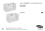
Recessed Side Entry
Bath Tubs
Model 3750
Model 3800
AFTER INSTALLATION, PLEASE CALL CUSTOMER SERVICE AT
1-800-668-2337 TO ARRANGE FOR AN IN-SERVICE ON THE TUB
DEALER: This manual MUST be given to
the user of the tub.
USER: BEFORE using this tub, read this
manual and save for future reference.
For more information regarding
Invacare products, parts, and services,
please visit www.invacare-ccg.com
WARNING
DO NOT USE THIS PRODUCT OR ANY AVAILABLE OPTIONAL EQUIPMENT
WITHOUT FIRST COMPLETELY READING AND UNDERSTANDING THESE
INSTRUCTIONS AND ANY ADDITIONAL INSTRUCTIONAL MATERIAL SUCH
AS OWNER’S MANUALS, SERVICE MANUALS OR INSTRUCTION SHEETS
SUPPLIED WITH THIS PRODUCT OR OPTIONAL EQUIPMENT. IF YOU ARE
UNABLE TO UNDERSTAND THE WARNINGS, CAUTIONS OR
INSTRUCTIONS, CONTACT A HEALTHCARE PROFESSIONAL, DEALER OR
TECHNICAL PERSONNEL BEFORE ATTEMPTING TO USE THIS EQUIPMENT OTHERWISE, INJURY OR DAMAGE MAY OCCUR.
THE INITIAL SET UP OF THIS TUB MUST BE PERFORMED BY A QUALIFIED
TECHNICIAN.
PROCEDURES OTHER THAN THOSE DESCRIBED IN THIS MANUAL MUST BE
PERFORMED BY A QUALIFIED TECHNICIAN.
ACCESSORIES WARNING
Invacare products are specifically designed and manufactured for use in conjunction
with Invacare accessories. Accessories designed by other manufacturers have not
been tested by Invacare and are not recommended for use with Invacare products.
For further information on this product, please call the following:
Customer Service ‐ 1‐800‐668‐2337
Technical Support ‐ 1‐800‐668‐2337
Recessed Side Entry Bath Tubs
2
Part No 1150695
TABLE OF CONTENTS
TABLE OF CONTENTS
SPECIAL NOTES ................................................................................ 5
LABEL LOCATION ............................................................................ 6
TYPICAL PRODUCT PARAMETERS .................................................... 7
FEATURES ........................................................................................ 8
3750 ...............................................................................................................................................................8
3800 ...............................................................................................................................................................9
SECTION 1—GENERAL GUIDELINES ................................................. 10
Important Safety Instructions ................................................................................................................10
Instructions Pertaining to a Risk of Fire, Electric Shock, or Injury to Persons .....................10
Installation ..................................................................................................................................................10
Electrical.................................................................................................................................................11
Plumbing .................................................................................................................................................11
Maintenance and Inspection...................................................................................................................12
Disinfecting.................................................................................................................................................12
Operation...................................................................................................................................................13
SECTION 2—PARTS AND INSTALLATION ........................................ 14
Parts Information......................................................................................................................................14
About Installation .....................................................................................................................................14
Installing the Tub ......................................................................................................................................15
Electrical and Plumbing Hook-up Locations on the Tub.................................................................17
Electrical Installation ................................................................................................................................18
Plumbing Installation ................................................................................................................................20
Post Installation Checklist ......................................................................................................................21
SECTION 3—OPERATION ................................................................ 22
Overview ....................................................................................................................................................22
Disinfecting the Tub Using the Closed Loop System.......................................................................23
Opening/Closing the Tub Door ............................................................................................................24
Opening the Tub Door.......................................................................................................................24
Closing the Tub Door.........................................................................................................................24
Tub Operation ..........................................................................................................................................24
Water Temperature Setting..............................................................................................................25
Operating Shower/Massage Wand ..................................................................................................26
Filling Tub...............................................................................................................................................26
Hydromassage.......................................................................................................................................27
SECTION 4—MAINTENANCE ........................................................... 29
Part No 1150695
3
Recessed Side Entry Bath Tubs
TABLE OF CONTENTS
TABLE OF CONTENTS
Safety Inspection Checklists...................................................................................................................29
Initially.....................................................................................................................................................29
Before Each Use ...................................................................................................................................29
Every 80-150 Baths..............................................................................................................................29
Every Six Months..................................................................................................................................29
Maintenance Overview............................................................................................................................30
Cleaning the Door Seal Gasket ........................................................................................................30
Removing Soap Film and Hard Water Deposits...........................................................................30
Removing Calcium Deposits, Scale and Lime Build-up ...............................................................30
Cleaning Your Tub...............................................................................................................................30
Heavy Duty Cleaning Procedure ..........................................................................................................31
Calibrating the Disinfectant Flow Meter.............................................................................................32
Maintenance Record ................................................................................................................................34
SECTION 5—TROUBLESHOOTING .................................................... 35
LIMITED WARRANTY ..................................................................... 36
Recessed Side Entry Bath Tubs
4
Part No 1150695
SPECIAL NOTES
SPECIAL NOTES
Signal words are used in this manual and apply to hazards or unsafe practices which could result in personal injury or property damage. Refer to the following table for definitions of the signal words.
SIGNAL WORD
DANGER
MEANING
Danger indicates an imminently hazardous situation which, if not avoided, will result in
death or serious injury.
WARNING
Warning indicates a potentially hazardous situation which, if not avoided, could result in
death or serious injury.
CAUTION
Caution indicates a potentially hazardous situation which, if not avoided, may result in
property damage or minor injury or both.
NOTICE
THE INFORMATION CONTAINED IN THIS DOCUMENT IS SUBJECT TO
CHANGE WITHOUT NOTICE.
WARNING
RADIO FREQUENCY INTERFERENCE
Most electronic equipment is influenced by Radio Frequency Interference (RFI).
CAUTION should be exercised with regard to the use of portable communication
equipment in the area around such equipment. If RFI causes erratic behavior, turn
the power off IMMEDIATELY. DO NOT turn the power on while transmission is in
progress.
MAINTENANCE
Maintenance MUST be performed only by qualified personnel.
Information on maintenance and adjustment of the thermoscopic mixing valve
(RADA) is in the RADA Owner’s Manual which is included with this product.
Use this unit only for its intended use as described in this manual. DO NOT use
attachments not recommended by the manufacturer.
Part No 1150695
5
Recessed Side Entry Bath Tubs
LABEL LOCATION
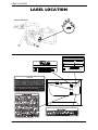
LABEL LOCATION
Interior Hardware
These labels are located inside the service door.
%+
"#$
%
#&$"''()
'./.0'12).3'1"4.(
%#<==9
#
#<
#%
%
,
!
%
!
#%
+(.@8&'
!/8.(
%#
&)1'7.00.3+./29:;9
U.S. AND
FOREIGN
PATENTS
PENDING
MODEL NO.
SERIAL NO.
#
5
%8
(.(6(723
(56('72
.72;
8'1
>?0
51
'?
0()
#%
#
!
#*
&
+##,
CAUTION
Some state and local plumbing codes require the
installation of a “reduced pressure zone” (RPZ) assembly
on both the incoming hot and cold supply lines to prevent
back flow contamination into the potable water system.
Invacare recommends you check local plumbing code
requirements to determine if RPZs are required on your
tub installation. RPZs are NOT supplied by Invacare and
are to be provided by the customer if required.
P/N 1150759 Rev A
Recessed Side Entry Bath Tubs
6
Part No 1150695
TYPICAL PRODUCT PARAMETERS
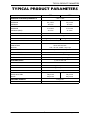
TYPICAL PRODUCT PARAMETERS
3750
3800
MINIMUM SPACE REQUIREMENTS:
7 feet x 6 feet
LENGTH
EXTERIOR:
INTERIOR:
59½ inches
49 inches
59½ inches
49 inches
WIDTH
EXTERIOR:
INTERIOR (SEAT):
31.5 inches
21 inches
31.5 inches
21 inches
DECK HEIGHT:
41.5 inches
SIDE ACCESS DOOR:
VOLUME CAPACITY:
40-inch swing
47 gallons (with user)
LIFT BASE CLEARANCE:
47 gallons (with user)
6¼ inches
WHIRLPOOL PUMP
SANITATION:
MOTOR:
Drain with back flush
1 HP, 115 VAC, 60 HZ, 5 amp input
JET OUTLETS:
2 adjustable/directional jets
TUB MATERIAL:
Gel coated fiberglass
THERMOMETER:
2-inch dial, 40° F to 140° F range
ANTI-SCALD WATER REGULATOR:
RADA 222 thermoscopic mixing valve
WATER SUPPLY:
¾ inch hot and cold
DRAIN SIZE:
2 inches
FILL RATE:
24 gallons per minute
DRAIN RATE:
25 gallons per minute
COLOR:
White or Bisque
WEIGHT
FILLED W/O USER:
EMPTY:
796 pounds
260 pounds
SHIPPING WEIGHT:
319 pounds
APPROVALS:
Part No 1150695
796 pounds
260 pounds
UL
7
Recessed Side Entry Bath Tubs
FEATURES
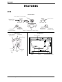
FEATURES
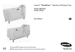
3750
Control Panel
Flow Water Thermometer
Tub Fill Valve
Shower ON/
OFF Valve
Whirlpool
ON/OFF Button
Water Temperature Control Valve
Tub Exterior
Tub Interior
Control Panel
(See Above)
Tub Spout
Drain
Drain
Plug
Whirlpool
Aerator Valve
Whirlpool
Inlet
Door Handle
Burp Fitting
Whirlpool
Jets
Seat
Recessed Side Entry Bath Tubs
8
Door
Service Access Door
Part No 1150695
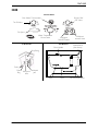
FEATURES
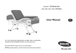
3800
Control Panel
Flow Water Thermometer
Shower ON/
OFF Valve
Tub Fill Valve
Tub Spout
Water Temperature
Control Valve
Whirlpool
ON/OFF Button
Tub Exterior
Tub Interior
Door Handle
Whirlpool
Aerator Valve
Control Panel
(See Above)
Burp Fitting
Drain
Drain
Plug
Whirlpool
Inlet
Whirlpool
Jets
Seat
Part No 1150695
9
Door
Service Access Door
Recessed Side Entry Bath Tubs
SECTION 1—GENERAL GUIDELINES
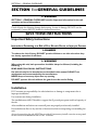
SECTION 1—GENERAL GUIDELINES
WARNING
SECTION 1 - GENERAL GUIDELINES contains important information for the safe
operation and use of this product.
Check all parts for shipping damage before using. In case of damage, DO NOT use the equipment. Contact the ICCG dealer for further instructions.
.
SAVE THESE INSTRUCTIONS
Important Safety Instructions
Instructions Pertaining to a Risk of Fire, Electric Shock, or Injury to Persons
DANGER
To reduce the risk of injury, DO NOT permit children to use this unit unless they
are closely supervised at all times.
WARNING
When using this unit, basic precautions should be always be followed, including the
following:
READ AND FOLLOW ALL INSTRUCTIONS.
Use this unit only for its intended use as described in this manual. DO NOT use
attachments not recommended by the manufacturer.
NEVER drop or insert any object into any opening.
DO NOT operate this unit without the guard over the suction fitting
Installation
ICCG assumes no responsibility for code infractions or damage to components due to improper installation.
Use extreme care during installation.
The installation area MUST be able to support the 65 pounds per square inch load capacity of the tub.
After installation and before use ensure all parts are properly and securely installed.
Ensure bathroom floor is dry and free of obstructions before transporting or assembling the unit.
Access for servicing the tub MUST be provided. If necessary, install a service access panel in the wall with a minimum size of 16 x 14‐inches.
Recessed Side Entry Bath Tubs
10
Part No 1150695
SECTION 1—GENERAL GUIDELINES
Electrical
Be certain ALL electrical work is performed by a qualified electrician and is in compliance with local electrical codes.
ALL electrical connections are to be water resistant.
Grounding
DANGER
Grounding is required. The unit should be installed and grounded by a qualified
service representative.
WARNING
The unit MUST be connected only to a supply circuit that is protected by a ground
fault circuit-interrupter (GFCI). Such a GFCI should be provided by the installer and
should be tested on a routine basis. To test the GFCI, push the test button. The
GCFI should interrupt power. Push the resest button. Power should be restored. If
the GCFI fails to operate in this manner, GFCI is defective. If the GFCI interrupts
power to the bathtub without the test button being pushed, a ground current is
flowing, indicating the possibility of an electric shock. DO NOT use this hydro
massage bathtub. Disconnect the hydro massage bathtub and have the problem
corrected by a qualified service representative before using.
A GREEN-colored terminal (or a wire connector marked “G,” “GR,” “Ground,” or
“Grounding”) is provided within the terminal compartment. To reduce the risk of
electric shock, connect this terminal or connector to the grounding terminal of your
electric service or supply panel with a conductor equivalent in size to the circuit
conductors suppling this equipment.
Plumbing
Be certain ALL plumbing work is performed by a qualified plumber.
Some state and local plumbing codes require the installation of a “reduced pressure zone” (RPZ) assembly on both the incoming hot and cold supply lines to prevent back flow contamination into the potable water system. Invacare recommends you check local plumbing code requirements to determine if RPZs are required on your tub installation. RPZs are NOT supplied by Invacare and are to be provided by the customer if required.
The hot water supply to the tub MUST NOT exceed 110° F (43° C) to protect the user from scalding.
When operating water pressure exceeds 55 p.s.i., pressure regulators (similar to the ¾‐
inch Watts U5) MUST be installed.
Part No 1150695
11
Recessed Side Entry Bath Tubs
SECTION 1—GENERAL GUIDELINES
Maintenance and Inspection
DANGER
ELECTRICAL SHOCK HAZARD. All disassembly and maintenance of the tub
MUST be done by a qualified technician, certified electrician or plumber.
Disconnect electrical supply or turn off circuit breaker before performing any
maintenance to the tub.
If any part of the system is not functioning properly, DO NOT use the system. Have the system serviced to correct the problem.
The system MUST be maintained on a regular basis to ensure it is functioning properly.
Disinfecting
Disinfect the tub after initial set up and ALWAYS disinfect the tub after each use to avoid resident infection and contamination of the tub.
DO NOT disinfect the tub when it is occupied otherwise injury may occur.
ALWAYS wear gloves, protective apron, and face shield protection when disinfecting or cleaning your tub.
ALWAYS handle disinfectants, cleaning compounds, and powdered sanitizers with extreme care. Physical or mechanical damage caused by improper handling or usage of such products will not be the responsibility of ICCG.
DO NOT attempt to turn on whirlpool pump during the disinfectant cycle. Doing so could result in skin or eye contact with the disinfectant, which is corrosive. If contact is made, rinse IMMEDIATELY with water. If irritation occurs, consult a physician. ALWAYS read and follow disinfectant label directions carefully.
NEVER use abrasive cleaners like scouring powder or liquid cleaners containing pumice stone. The use of these types of cleaners will make the gel‐coat finish of your tub scratched and dull. NEVER use cleaners containing iodine, bromine, Betadine® or methylene blue. The use of these types of cleaners will cause the tub to stain. Never use cleaners containing bleach. Use of these types of cleaners will dry out the rubber seals and gaskets and the tub will not function properly.
Recessed Side Entry Bath Tubs
12
Part No 1150695
SECTION 1—GENERAL GUIDELINES
Operation
DANGER
Keep hair and body away from suction guard when pump is running.
The causes, symptoms, and effects of hyperthermia may be described as follows:
Hyperthermia occurs when the internal temperature of the body reaches a level
several degrees above the normal body temperature of 98.6° F. The symptoms of
hyperthermia include an increase in the internal temperature of the body, dizziness,
lethargy, drowsiness, and fainting. The effects of hyperthermia include:
• Failure to perceive heat
• Failure to recognize the need to exit the spa or hot tub
• Unawareness of impending hazard
• Fetal damage in pregnant women
• Physical inability to exit the spa or hot tub
• Unconsciousness resulting in the danger of drowning
The use of alcohol, drugs, or medication can greatly increase the risk of fatal
hyperthermia.
NEVER operate whirlpool without water level above the whirlpool jets. Severe pump damage will result.
DO NOT operate this unit without the guard over the (water intake) suction fitting. The guard is a safety device that reduces the potential hazard of hair or body entrapment. To reduce the risk of injury, DO NOT permit children or infirm persons to use this unit unless they are supervised at all times.
Recommended length of a bath is 5 to 10 minutes. However, if you become nauseous or dizzy or develop a headache, get out at once and cool down. Get medical attention if symptoms persist. Also, check with a physician before using this unit again.
Anyone under a doctorʹs supervision, pregnant, or with poor health, should check with a physician before using this unit.
Part No 1150695
13
Recessed Side Entry Bath Tubs
SECTION 2—PARTS AND INSTALLATION
SECTION 2—PARTS AND
INSTALLATION
Parts Information
For parts information, please contact ICCG Technical Service at (800) 668‐2337.
About Installation
WARNING
Access for servicing the tub MUST be provided. If necessary, install a service access
panel in the wall with a minimum size of 16 x 14-inches.
CAUTION
The door MUST be closed and latched during installation to avoid deformation of
the tub shell.
DO NOT lift the tub by the plumbing.
DO NOT remove or relocate the pump. Modifications to the pump location may
cause the system to malfunction and will void the warranty.
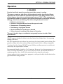
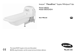
NOTE: For this procedure, refer to FIGURE 2.1.
The tubs are designed to be built‐in against one, two or three walls, much the same way a traditional tub/shower unit is installed in an alcove. Optional end panels are available for corner or one wall installation and are only available at the time of tub order.
One Wall Installation Wall Mount
Two Wall Installation Corner Mount
Three Wall Installation Recess Mount
FIGURE 2.1 Tub and surrounding wall configurations
Recessed Side Entry Bath Tubs
14
Part No 1150695
SECTION 2—PARTS AND INSTALLATION
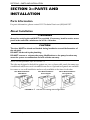
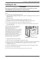
Installing the Tub
WARNING
Protective eye wear MUST be worn when drilling to avoid possible eye injury.
The tub MUST be supported by the floor and not the deck.
NOTE: For this procedure, refer to FIGURE 2.2, FIGURE 2.3 on page 16 and FIGURE 2.4 on page 16.
1. Carefully remove the tub from the carton.
2. Inspect the tub for shipping damage or factory defects. If damage is found, contact the shipping carrier.
3. Measure the tub.
4. Ensure the floor of the installation location will support the tub.
5. Determine whether the unit will be built against one, two or three walls.
NOTE: Follow recommended floor plan when installing tub FIGURE 2.4.
6. Three wall installation only ‐ Ensure a stud wall “pocket” has been constructed to receive the tub unit. NOTE: If desired, a wooden nailer may be attached to stud walls as an additional mounting fixture for the tub.
NOTE: The opening of the “pocket” should be sized to allow the unit to slide in easily, without any binding between the studs and the tub unit. Minor gaps will be covered by drywall or paneling during the finishing stage. In remodeling situations where tub/shower units have been removed, it may be necessary to modify the opening to receive the tub.
FIGURE 2.2 Stud Wall “Pocket”
7. Temporarily slide the unit into place. 8. Mark the location of the fiberglass lip against the studs.
9. Mount 2‐inch x 2‐inch cleats approximately 1/8‐inch below the marks made in STEP 8.
10. Ensure the cleats to not interfere with any components of the unit or restrict installation in any way.
11. Ensure the plumbing and electrical lines have been routed to the proper location.
12. Ensure the unit is level and plumb.
NOTE: Use a 4‐foot level to level the tub from front to back and side to side.
Part No 1150695
15
Recessed Side Entry Bath Tubs
SECTION 2—PARTS AND INSTALLATION
13. Model 3750 Only ‐ Perform the following steps to install the shower wand:
A. Determine the mounting location for the shower wand and mark this on the wall. NOTE: A shower wand, shower hose, supply elbows, hanger pegs and a flexible supply line have been supplied with the tub.
B. Plumb the supply line to the diverted output port of the mix valve.
C. Route the supply line behind the back wall to the location of your choice.
D. Drill a hole in the wall to accommodate the plastic compression fitting on the back and the chrome elbow on the front. NOTE: It is advisable to “hard plumb” the shower supply elbow using standard copper pipe and brass fittings strapped to the studs behind the drywall or paneling.
Shower Supply
Line
FIGURE 2.3 Shower Wand Plumbing (Model 3750 Only)
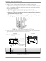
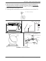
14. Install a service access panel (minimum 16 x 14‐inches) on the wall (the back wall or right wall) to allow the pump and controls to be serviced.
Top View
Front View
Model 3750 - Hot and Cold Water Stubs
On This End
B
Model 3800 Hot and Cold
Water Stubs
On This End
C
LETTER
D
E
Motor Pump Hookup
On This End
A
A
B
C
D
E
B
DESCRIPTION
LENGTH IN INCHES
Door Swing Clearance
Length of Tub
Tub Width
Tub Height
Seat Height
40 minimum (60 for wheelchair or lift access)
59.5
31.5
41.5
19
FIGURE 2.4 Installing the Tub
Recessed Side Entry Bath Tubs
16
Part No 1150695
SECTION 2—PARTS AND INSTALLATION
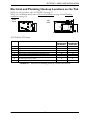
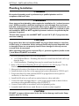
Electrical and Plumbing Hook-up Locations on the Tub
NOTE: For this procedure, refer to FIGURE 2.5 on page 17.
NOTE: For installation details refer to Electrical Installation on page 18 and Plumbing Installation on page 20.
Front
View
E
Top
View
D
AB C
FG H
NOTE: Model 3750 shown.
LETTER
DESCRIPTION
A
B
C
D
E
F
Height of Motor (Electrical) Input (115V AC, 60 Hz, 15A)
Height of ¾-inch Hot Water Stub with Recommended Shut Off Valve
Height of ¾-inch Cold Water Stub with Recommended Shut Off Valve
Height of 2-inch Drain Pipe (Center) from Floor
Distance of End of 2-inch Drain Pipe from Right End of Tub
Distance of Motor Input (115V AC, 60 Hz, 15A) from Front of Tub
Distance of ¾-inch Hot and Cold Water Stubs with Recommended
Shut Off Valves from Front of Tub
Distance of End of 2-inch Drain Pipe from Front of Tub
G
H
MODEL 3750 MODEL 3800
DIMENSIONS DIMENSIONS
IN INCHES
IN INCHES
18
31
34
5.25
20
7
18
31
34
5.25
15
7
8
21.5
8
17
FIGURE 2.5 Electrical and Plumbing Hook-up Locations on the Tub
Part No 1150695
17
Recessed Side Entry Bath Tubs
SECTION 2—PARTS AND INSTALLATION
Electrical Installation
DANGER
When using electrical products, basic precautions should always be followed,
including the following:
RISK OF ELECTRIC SHOCK. Connect the bathtub only to a circuit protected by a
ground-fault circuit-interrupter (GFCI). Use a 15 AMP GFCI breaker only.
The National Electric Code requires the use of a ground fault circuit interrupter on
all therapeutic pools and tubs (hydrotherapeutic tanks). Failure to follow this
requirement could result in serious or fatal injury.
Grounding is required. The ground wire MUST be continuous from the motor to
the GFCI service panel.
ELECTRICAL SHOCK HAZARD. All disassembly and maintenance of the tub
MUST be done by a qualified technician, certified electrician or plumber. Be certain
all electrical work is in compliance with local electrical codes.
All electrical connections are to be water resistant.
Disconnect electrical supply or turn off the circuit breaker before performing any
maintenance to the tub to avoid electrical shock.
WARNING
All electrical conduit, fittings and wire to unit are to be supplied and installed by a
professional electrician in accordance with the National electrical code as a
minimum requirement, including the supply and installation of a Ground Fault
Circuit Interrupter (GFCI).
For Canadian installation, ground fault interrupter and a 30-minute maximum
timer MUST be installed in the electrical circuit. (parts not supplied by ICCG). The
unit must be operated through the circuit. The 30-minute timer must be located in
a position where a person in the unit cannot reach the timer.
NOTE: For this procedure, refer to FIGURE 2.6 on page 19.
NOTE: Use 15 AMP GFCI breaker only.
1. Ensure a 15 AMP GFCI breaker is installed to protect the unit.
2. Connect the green terminal to the grounding terminal of the electric service supply panel using a continuous green insulated copper wire equivalent in size to the circuit conductors supplying this equipment, but no smaller than No. 8AWG (3.3 mm).
NOTE: The green terminal may be a wire connector marked “G”, “GR”, “Ground” or “Grounding”.
3. Use the pressure wire connector on the exterior of the terminal box to connect the No. 8AWG (8.4 mm) solid copper bonding conductor between the unit and all other electrical equipment and exposed metal in the vicinity, to comply with local requirements.
4. Use a pneumatic air switch with the push button located on the tub deck for On/Off switching.
5. Install a 115 V electrical hook‐up per local electrical codes through a dedicated GFCI circuit.
Recessed Side Entry Bath Tubs
18
Part No 1150695
SECTION 2—PARTS AND INSTALLATION
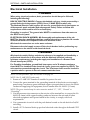
6. Open the service access panel to access pump electric connections (Detail “A”).
7. Route electrical line through electrical line routing hole. Refer to Electrical and Plumbing Hook‐up Locations on the Tub on page 17 for the location of this hole.
8. Remove the motor cover (Detail “C”).
9. Connect ground, neutral and hot wires from wall directly to motor (Detail “D”).
115 V Electrical Hook-up
DETAIL “A” - ACCESS PANEL
DETAIL “B” - ELECTRICAL SCHEMATIC
Service Access Panel
GREEN WHITE BLACK
Wall
Tub Wall
Pump
Motor
DETAIL “C” - MOTOR COVER
DETAIL “D” - MOTOR END PLATE
Air Switch Line
Ground (GREEN)
Motor
Cover
Line
Line (BLACK)
Neutral (WHITE)
Neutral
Ground
FIGURE 2.6 Electrical Installation
Part No 1150695
19
Recessed Side Entry Bath Tubs
SECTION 2—PARTS AND INSTALLATION
Plumbing Installation
DANGER
Be certain all plumbing work is performed by a qualified plumber and is in
compliance with local codes.
WARNING
Some state and local plumbing codes require the installation of a “reduced pressure
zone” (RPZ) assembly on both the incoming hot and cold supply lines to prevent
back flow contamination into the potable water system. Invacare recommends you
check local plumbing code requirements to determine if RPZs are required on your
tub installation. RPZs are NOT supplied by Invacare and are to be provided by the
customer if required.
The hot water supply to the tub MUST NOT exceed 110° F (43° C) to protect the
user from scalding.
CAUTION
Purge water lines. Hot and cold lines MUST be purged (blown down) to clear lines
of debris prior to connection. Valves and spray heads may become inoperable and/
or damaged if lines are not properly cleared. Items damaged in this way are not
covered under the warranty.
When operating water pressure exceeds 55 p.s.i., pressure regulators (similar to the
¾-inch Watts U5) MUST be installed.
1. Route the plumbing lines in the following manner: • 1 or 2 Wall Installation ‐ Plumbing lines must be routed from the back wall or up from the floor.
• 3 Wall Installation ‐ Plumbing lines may be routed from the side wall.
2. Refer to Electrical and Plumbing Hook‐up Locations on the Tub on page 17 for the location of the tub drain, hot water stub and cold water stub.
3. Measure the location of the drain on the unit as an extra precaution.
4. Install the drain in the floor in the appropriate location determine in STEPS 2 and 3.
5. Purge water lines. Hot and cold lines MUST be purged (blown down) prior to connection, to clear lines of debris.
6. Install On/Off valves at wall and use unions between valves and stubs.
7. Connect hot and cold supply lines to ¾‐inch copper pipes found on back of tub in accordance with applicable building codes (FIGURE 2.7).
8. Connect 2‐inch drains in accordance with local plumbing codes.
9. Assemble hand held shower wand. Be sure to use the washers supplied.
CAUTION
DO NOT run pump without water in the tub. Serious damage could result. Pump
requires water for cooling.
Recessed Side Entry Bath Tubs
20
Part No 1150695
SECTION 2—PARTS AND INSTALLATION
10. Check for leaks in supply or drain lines and check operation of tub. Refer to Operation on page 22.
NOTE: Check local codes regarding maximum water temperature allowed at hot water outlets for facility type.
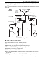
Plumbing
Schematic
Optional
Pressure
Regulator
HOT
In House
Water Service
COLD
RADA Mixing Valve
Shower
Control Valve
Tub Fill Valve
Tub Spout
(Nearest
Tub)
Disinfectant Injector
Backflow
Preventor
Back Flow
Preventer
Flowmeter
3-Way
Selector
Valve
Check
Valve
Burp
Fitting
Check
Valve
Pump
ICCG
Disinfectant
Suction Return Line
FIGURE 2.7 Plumbing Installation
Post Installation Checklist
Before putting the tub into service, check the following:
❑ Water lines have been purged of any foreign matter.
❑ Both hot and cold water lines are properly connected to tub.
❑ Dedicated 115V 15AMP AC power line is properly wired to unit.
❑ Power line is protected by a 15AMP GFCI.
❑ All water lines are checked for leaks.
❑ ICCG skin care and cleaning products have been ordered. To place your order, call 800‐668‐2337.
❑ ICCG representative has been called at 800‐668‐2337 to arrange for an In‐Service on tub.
Part No 1150695
21
Recessed Side Entry Bath Tubs
SECTION 3—OPERATION
SECTION 3—OPERATION
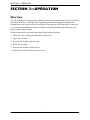
Overview
The tub is designed to improve the efficiency and environmental safety of your facilityʹs operation. However, if the tub is not operated or maintained properly, the benefits designed into the system will not be realized. The purpose of this manual is to provide you with recommended procedures to help you obtain the maximum efficiency and safety while using your tub.
When using the tub, perform these steps in the following order:
1. Make sure the tub has been disinfected before use.
2. Open the tub door.
3. Transfer the resident into the tub.
4. Bathe the resident.
5. Transfer the resident from the tub.
6. Disinfect the tub, including the door seal.
Recessed Side Entry Bath Tubs
22
Part No 1150695
SECTION 3—OPERATION
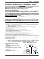
Disinfecting the Tub Using the Closed Loop System
WARNING
Disinfect the tub after EACH use to avoid resident infection and contamination of the tub.
DO NOT disinfect the tub when it is occupied otherwise injury may occur.
Read and understand all information on Invacare brand disinfectant before use.
ALWAYS wear rubber gloves, an apron and a face shield when using disinfectant. In case of eye or skin contact,
follow procedures on disinfectant container.
The disinfectant dispensing system has been factory tested and calibrated for use with Invacare disinfectant.
The use of any disinfectant with a dilution ratio (½ oz. per gallon) or viscosity level different than that of
Invacare disinfectant will result in an improper mixture of disinfectant and water. This may cause your system
to be improperly disinfected - or in some instances, not disinfected at all. If using any disinfectant with a dilution
ratio or viscosity level different than that of Invacare disinfectant or if switching from one type of disinfectant to
another type, the disinfectant flowmeter MUST be calibrated before performing this procedure. Refer to
Calibrating the Disinfectant Flow Meter on page 32.
CAUTION
NEVER use abrasive cleaners like scouring powder or liquid cleaners containing pumice stone. The use of
these types of cleaners will make the gel-coat finish of your tub scratched and dull. NEVER use cleaners
containing iodine, bromine, Betadine or methylene blue. The use of these types of cleaners will cause the
tub to stain. Never use cleaners containing bleach. Use of these types of cleaners will dry out the rubber
seals and gaskets and the tub will not function properly.
NOTE: For this procedure, refer to FIGURE 1.
NOTE: Ensure that the whirlpool jets and whirlpool inlet fitting are closed before starting this procedure.
1. Clean the entire tub surface to remove visible tissue residue and fluid.
2. Depending on the type of whirlpool jets that are in your tub, close all jets by performing one of the following: • Turn the center of the jet clockwise to a full stop.
• Push the center of the jet in.
3. Close the whirlpool inlet by gently pulling the plug in the center of the inlet cover outward until it stops.
4. Open aerator by rotating aerator knob two turns counter‐clockwise.
5. Open disinfectant cabinet.
6. Ensure that disinfectant siphon tube is placed in disinfectant container.
7. If tub is equipped with a disinfectant wand, hold the wand over the interior of the tub.
8. Adjust water temperature to 105°F (40°C).
9. Turn disinfectant On/Off valve to the On position.
NOTE: Liquid will begin flowing from the disinfectant wand into the tub (if so equipped).
10. Turn the adjustment knob on the flowmeter until the floating ball rises to a level of 35 cc/min.
NOTE: At 35 cc/min., disinfectant is being mixed with water at the proper ratio.
11. Continue to hold the disinfectant wand over the interior of the tub (if so equipped).
NOTE: When disinfectant has totally filled the interior plumbing, liquid will begin to flow from the burp fitting located inside the tub bowl near the rim or from the disinfectant wand.
NOTE: Invacare recommends that you thoroughly scrub all interior surfaces of the tub with disinfectant. The use of a long‐handled brush will make this operation easier.
12. Perform one of the following:
• Allow some liquid to pool in the bottom of the tub. Scrub all interior surfaces of the tub, including the whirlpool jets, overflow fitting and whirlpool inlet fitting with disinfectant.
• If the tub is equipped with a disinfectant wand, spray the interior surfaces of the tub, including the whirlpool jets, overflow fitting and whirlpool inlet fitting with disinfectant. Scrub all interior surfaces.
13. Turn the disinfectant On/Off valve to the Off DETAIL “A” - WHIRLPOOL JET AND INLET DETAILS
position.
Whirlpool Jet
14. Return disinfectant wand to its holder (if so Turn Clockwise to
Push In To Close
Close
equipped).
15. After scrubbing the interior surfaces, leave the Whirlpool Inlet
Plug
disinfectant in the loop and on the tub surfaces for ten minutes.
DETAIL “B” - DISINFECTING
DETAIL “C” - FLOWMETER
CABINET
16. Use the shower/massage wand on the pulse setting DETAILS
Disinfectant Valve
and direct the spray into both whirlpool jets to back Adjustment
flush until the water discharging from the whirlpool Flowmeter
Flowmeter
Knob
inlet is clear.
17. Rinse all interior tub surfaces.
Disinfecting
Cabinet
18. Reverse STEPS 2 and 3 to open the whirlpool jets and inlet.
Disinfectant
Ball
Siphon Tube
FIGURE 1 Disinfecting the Tub Using the Closed Loop System
Part No 1150695
23
Recessed Side Entry Bath Tubs
SECTION 3—OPERATION
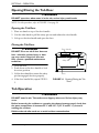
Opening/Closing the Tub Door
WARNING
DO NOT open door when water is in the tub, serious injury could result.
NOTE: For this procedure, refer to FIGURE 3.1 on page 24.
Opening the Tub Door
1. Place one hand on top of the door handle.
2. Use the other hand to pull the safety pin out and release the door handle.
3. Lift up on the door handle and open the door.
Closing the Tub Door
Door Handle
WARNING
DO NOT fill or use tub if door does not
lock - otherwise serious injury or damage may result. If the door does not
lock, contact a qualified maintenance
technician.
Safety Pin
1. Close the door.
2. Push down on the door handle to lock door into position.
Door
3. Lift the door handle to ensure the safety pin has engaged the door properly.
FIGURE 3.1 Opening/Closing the Tub
Door
4. If the door handle lifts, repeat STEPS 1‐
3.
Tub Operation
WARNING
DO NOT stand in tub. Tub surfaces are slippery when wet. Serious injury may
occur.
Before immersing the resident or operating the shower/massage wand, check that
the water temperature is between 95° F and 105° F (35° C and 41° C) to avoid
scalding the resident.
Disinfect the tub after each use to avoid resident contamination.
Recessed Side Entry Bath Tubs
24
Part No 1150695
SECTION 3—OPERATION
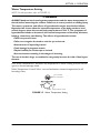
Water Temperature Setting
NOTE: For this procedure, refer to FIGURE 3.2.
DANGER
ALWAYS hand test the incoming water temperature and the water temperature in
the tub before immersing the resident. Failure to do so may result in a scalding injury.
The causes, symptoms, and effects of hyperthermia may be described as follows:
Hyperthermia occurs when the internal temperature of the body reaches a level
several degrees above the normal body temperature of 98.6° F. The symptoms of
hyperthermia include an increase in the internal temperature of the body, dizziness,
lethargy, drowsiness, and fainting. The effects of hyperthermia include:
•Failure to perceive heat
•Failure to recognize the need to exit the spa or hot tub
•Unawareness of impending hazard
•Fetal damage in pregnant women
•Phyical inability to exit the spa or hot tub
•Unconsciousness resulting in the danger of drowning
The use of alcohol, drugs, or medication can greatly increase the risk of fatal hyperthermia.
Flow Water Thermometer ‐ measures the temperature of water coming from the tub fill spout or shower/massage wand.
Water Temperature Control Valve ‐ sets and maintains constant temperature for all incoming water.
Flow Water
Thermometer
Water Temperature Valve
FIGURE 3.2 Water Temperature Setting
Part No 1150695
25
Recessed Side Entry Bath Tubs
SECTION 3—OPERATION
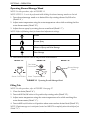
Operating Shower/Massage Wand
NOTE: For this procedure, refer to FIGURE 3.3.
NOTE: STEPS 1 ‐ 3 are to be performed while holding the shower/massage wand over the tub.
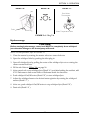
1. Turn shower/massage wand on to desired flow by rotating shower On/Off valve (Detail “A”).
2. Adjust water temperature using the water temperature valve while watching the flow water thermometer (Detail “B”).
3. Adjust shower spray by rotating shower wand head (Detail “C”).
NOTE: Refer to following chart for shower head adjustment settings.
Stream
Shower Spray
Mixture of Spray and Pulse Massage
Pulse Massage
4. Turn shower On/Off valve to off position when finished.
DETAIL “A”
DETAIL “B”
DETAIL “C”
Flow Water
Thermometer
Shower/Massage
Wand
Head
Shower On/Off Valve
Water Temperature Valve
FIGURE 3.3 Operating Shower/Massage Wand
Filling Tub
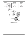
NOTE: For this procedure, refer to FIGURE 3.4 on page 27.
1. Close the drain (Detail “A”).
2. Turn tub fill On/Off valve to On position by rotating valve (Detail “B”).
3. Adjust water temperature using the water temperature valve while watching flow water thermometer (Detail “C”).
4. Turn tub fill on/off valve to off position when water reaches desired level (Detail “B”).
NOTE: If hydromassage use is anticipated, water level MUST be completely above the whirlpool jets (Detail “A”).
Recessed Side Entry Bath Tubs
26
Part No 1150695
SECTION 3—OPERATION
DETAIL “A”
DETAIL “B”
Jets
Drain
DETAIL “C”
Flow Water
Thermometer
Drain Plug
Water Temperature Valve
FIGURE 3.4 Filling Tub
Hydromassage
CAUTION
Before starting hydromassage, water level MUST be completely above whirlpool
jets otherwise damage to the motor/pump will result.
NOTE: For this procedure, refer to FIGURE 3.5.
1. Close the aerator by rotating the aerator valve two turns clockwise.
2. Open the whirlpool inlet by pushing the inlet plug in.
3. Open all whirlpool jets by pulling the center of the whirlpool jet out or rotating the center counterclockwise.
4. Fill the tub. Refer to Filling Tub on page 26.
5. After water level covers whirlpool jets (Detail “A”) and after bathing the resident, add ICCG Defoamer to bath water. Refer to Defoamer bottle for directions.
6. Push whirlpool On/Off button (Detail “B”) to start whirlpool jets.
7. Adjust the whirlpool aerator for desired water agitation by rotating the whirlpool aerator (Detail “C”).
8. After use, push whirlpool On/Off button to stop whirlpool jets (Detail “B”).
9. Drain tub (Detail “A”). Part No 1150695
27
Recessed Side Entry Bath Tubs
SECTION 3—OPERATION
DETAIL “A”
DETAIL “B”
DETAIL “C”
Whirlpool
Aerator
Whirlpool On/Off
Button
Drain Plug
Drain
Whirlpool Jet
Turn
Counterclockwise
to Open
Pull Out to
Open
Inlet Plug
Whirlpool Inlet
FIGURE 3.5 Hydromassage
Recessed Side Entry Bath Tubs
28
Part No 1150695
SECTION 4—MAINTENANCE
SECTION 4—MAINTENANCE
NOTE: Every six months or as necessary have a qualified technician perform a thorough inspection and servicing. Routine maintenance will extend the life and efficiency of your tub.
Safety Inspection Checklists
Initially
❑ Ensure that the maximum water supply temperature does not exceed 115° F.
❑ Ensure that the maximum water pressure does not exceed 65 PSI.
❑ Verify the water flow temperature with a separate thermometer.
❑ Visually inspect for cracks in the tub surface.
❑ Ensure that the door handle locks the door closed.
❑ Ensure that the safety pin properly engages the door.
❑ Check that all labels are present and legible. Replace if necessary.
Before Each Use
❑ Disinfect the tub.
❑ Ensure that the maximum water supply temperature does not exceed 115° F.
❑ Ensure that the maximum water pressure does not exceed 65 PSI.
❑ Visually inspect for cracks in the tub surface.
❑ Ensure that the door handle locks the door closed.
❑ Ensure that the safety pin properly engages the door.
Every 80-150 Baths
❑ Perform the heavy duty cleaning procedure on the tub. Refer to Heavy Duty Cleaning Procedure on page 31.
Every Six Months
❑ Verify the water flow temperature with a separate thermometer.
❑ Check that all labels are present and legible. Replace if necessary.
❑ Clean RADA valve to remove lime deposits.
Part No 1150695
29
Recessed Side Entry Bath Tubs
SECTION 4—MAINTENANCE
Maintenance Overview
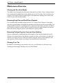
Cleaning the Door Seal Gasket
The rubber door seal gasket should remain clean and free of debris. Use a working solution of a commercially available heavy duty cleaner such as ICCGʹs Heavy Duty Cleaner and a sponge to thoroughly wipe the entire length of the rubber seal, making sure to remove all traces of soap scum and other debris.
Removing Soap Film and Hard Water Deposits
Use a commercially available cleaner such as ICCGʹs Heavy Duty Cleaner to thoroughly spray the exposed surfaces, including the openings of the tub jets and tub suction fitting. Use a long handled soft brush or similar product to wipe down all surfaces and allow the heavy duty cleaner to remain in contact with the exposed surfaces for approximately ten minutes. Rinse off surfaces using the shower wand, adjusted to spray position.
Removing Calcium Deposits, Scale and Lime Build-up
Spray a commercially available cleaner (full strength) for the intended application on all surfaces to be cleaned. Allow the cleaner to remain in contact with surfaces for at least five minutes to as long as 12 hours. Rinse off surfaces using the shower wand, adjusted to the spray position. Use the cleaner according to the manufacturerʹs instructions.
Cleaning Your Tub
In addition to disinfecting your tub after every use, you will need to do the heavy duty cleaning procedure approximately once every 80‐150 baths.
Recessed Side Entry Bath Tubs
30
Part No 1150695
SECTION 4—MAINTENANCE
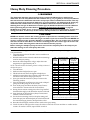
Heavy Duty Cleaning Procedure
WARNING
The disinfectant dispensing system has been factory tested and calibrated for use with Invacare
disinfectant. The use of any disinfectant with a dilution ratio (½ oz. per gallon) or viscosity level different
than that of Invacare disinfectant will result in an improper mixture of disinfectant and water. This may
cause your system to be improperly disinfected - or in some instances, not disinfected at all. If using any
disinfectant with a dilution ratio or viscosity level different than that of Invacare disinfectant or if
switching from one type of disinfectant to another type, the disinfectant flowmeter must be calibrated
before performing this procedure. Refer to Calibrating the Disinfectant Flow Meter on page 32.
ALWAYS wear rubber gloves, an apron and face shield protection during disinfecting, cleaning and
rinsing procedures. In case of eye or skin contact, follow procedures on disinfectant container.
CAUTION
NEVER use abrasive cleaners like scouring powder or liquid cleaners containing pumice stone. The
use of these types of cleaners will make the gel-coat finish of your tub scratched and dull. NEVER use
cleaners containing iodine, bromine, Betadine or methylene blue. The use of these types of cleaners
will cause the tub to stain. Never use cleaners containing bleach. Use of these types of cleaners will
dry out the rubber seals and gaskets and the tub will not function properly.
Before starting the whirlpool pump, the water level must be completely above the whirlpool jets.
Otherwise damage to the motor/pump will result.
In addition to disinfecting your tub after every use, you will need to perform this procedure approximately once every 80‐150 baths.
1. Clean the entire surface of the tub to remove visible tissue residue and fluid.
INVACARE
WATER REQUIRED
TUB
2. Rinse the inside surface of the tub with the shower/massage HEAVY DUTY
TO COVER JETS
MODEL
wand on the spray setting.
CLEANER
(GALLONS)
NUMBER
3. Rotate the water temperature valve to adjust the water REQUIRED (OZ)*
temperature to approximately 105o F.
2800
10
40
NOTE: This will maximize the cleaning solutionʹs ability to clean and 2001
32
128
disinfect the system.
3700
30
120
3750
30
120
4. Close the drain.
3800
30
120
5. Make sure the whirlpool jets are open.
3600
30
120
6. Fill the tub one inch above the highest whirlpool jets.
3650
48
192
7. Add the Invacare Heavy Duty Cleaner to the water in the 3600XL
48
192
tub. Refer to the chart for the proper amount.
2300
25
100
8. Spray pre‐mixed Invacare Heavy Duty Cleaner on the 3300
30
120
remaining surfaces.
4300
35
140
4300HL
35
140
9. Press the whirlpool on/off button to turn on the whirlpool 5300
52
208
pump and let the pump run for 60 seconds.
5300HL
52
208
10. Turn off the pump and allow the Heavy Duty Cleaner/
6300
50
200
water solution to remain in the tub for 10 minutes. 6300ADH
50
200
11. During this ten‐minute waiting time, take a long handled 4400SS
48
192
brush and thoroughly scrub all interior surfaces of the tub.
5400SS
50
200
12. Open the drain to allow the Heavy Duty Cleaner/water *NOTE: If using non‐Invacare heavy duty solution to drain from the tub. cleaner, refer to the instructions supplied with the 13. Use the shower/massage wand on the pulse setting and cleaner to determine the proper amount required.
direct the spray into both whirlpool jets to back flush until the water discharging from the whirlpool inlet is clear.
14. Rinse the tub thoroughly with the shower wand on the spray setting.
15. Check the tub for damage and to ensure all surfaces of the tub are clean and that no visible residue remains. If residue is found, repeat STEPS 13 and 14
Part No 1150695
31
Recessed Side Entry Bath Tubs
SECTION 4—MAINTENANCE
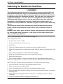
Calibrating the Disinfectant Flow Meter
WARNING
The disinfectant dispensing system has been factory tested and calibrated for use
with Invacare disinfectant. The use of any disinfectant with a dilution ratio (½ oz.
per gallon) or viscosity level different than that of Invacare disinfectant will result in
an improper mixture of disinfectant and water. This may cause your system to be
improperly disinfected - or in some instances, not disinfected at all. If using any
disinfectant with a dilution ratio or viscosity level different than that of Invacare
disinfectant or if switching from one type of disinfectant to another type, the
disinfectant flowmeter MUST be calibrated using this procedure before disinfecting
the tub.
This procedure should only be attempted by qualified maintenance personnel.
Failure to heed these precautions could result in injury to the tub operator or
resident.
ALWAYS wear rubber gloves, an apron and face shield protection during disinfecting, cleaning and rinsing procedures. In case of eye or skin contact, follow procedures on disinfectant container.
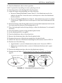
NOTE: For this procedure, refer to FIGURE 4.1 on page 33.
NOTE: Equipment needed:
• Bucket or Pail, at least 1 Gallon
• Graduated plastic bottle, at least 16 ounces
• Felt Tip Pen
1. Open the whirlpool aerator by rotating two turns counterclockwise.
2. If the tub is equipped with a disinfectant wand, hold the wand over the interior of the tub.
3. Pour exactly one gallon of water into the bucket/pail.
4. Mark the bucket/pail at the gallon level using the felt tip pen.
5. Empty the bucket/pail.
6. Pour a whole number of ounces of disinfectant into the graduated plastic bottle.
NOTE: For example, pour 2 or 3‐ounces, but not 2½‐ounces, otherwise the results will be skewed.
NOTE: DO NOT use water instead of disinfectant. This would cause a false reading.
7. Note the number of ounces in the graduated plastic bottle.
8. Open the service access cabinet door.
9. Insert the disinfectant draw tube into the graduated plastic bottle.
10. Turn the black knob on the flow meter valve five turns counterclockwise to open the metering valve.
11. Close all jets by pushing the center of each jet in or turning the center of the jet clockwise.
12. Close the whirlpool inlet by pulling the inlet plug out.
Recessed Side Entry Bath Tubs
32
Part No 1150695
SECTION 4—MAINTENANCE
13. Turn the disinfectant valve to the on position.
NOTE: Liquid will be heard filling the interior plumbing of the tub.
14. Note the position of the floating ball in the flow meter. 15. Adjust the injector by performing one of the following:
• Bottom of Floating Ball Reads Greater Than 35 ‐ Less disinfectant needs to be added to the mixture. Loosen the screw on the injector to draw less disinfectant into the solution.
• Bottom of Floating Ball Reads Less Than 35 ‐ More disinfectant needs to be added to the mixture. Tighten the screw on the injector to draw more disinfectant into the solution.
16. When the bottom of the floating ball is near 35, turn the black adjustment knob on the flow meter until the bottom of the floating ball is at 35.
17. Place the bucket/pail under the burp fitting to collect the disinfectant. Use a funnel if necessary. 18. Note the number of ounces in the graduated plastic bottle.
19. Let the bucket/pail fill to one gallon.
20. Turn the disinfectant valve to the off position.
21. Remove the disinfectant draw tube from the plastic bottle.
22. Examine the amount of disinfectant remaining in the plastic bottle. 23. Subtract the amount of disinfectant remaining from the amount noted in STEP 18. 24. Perform one of the following: • Approximately ½‐ounce of disinfectant has been used ‐ Proceed to STEP 23.
• Much more or much less than ½‐ounce of disinfectant has been used ‐ repeat STEPS 1‐18.
25. Position the disinfectant draw tube into the disinfectant solution.
26. Disinfect the tub. Refer to Disinfecting the Tub Using the Closed Loop System on page 23.
Disinfectant Siphon Tube
Injector
Disinfectant
Valve
Service
Access
Cabinet
DETAIL “A” FLOW METER
Flow Meter
Knob
Floating
Ball
Screw
FIGURE 4.1 Calibrating the Disinfectant Flow Meter
Part No 1150695
33
Recessed Side Entry Bath Tubs
SECTION 4—MAINTENANCE
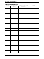
Maintenance Record
DATE
MAINTENANCE
PERSON
Recessed Side Entry Bath Tubs
TYPE OF MAINTENANCE
PERFORMED
34
NOTES
Part No 1150695
SECTION 5—TROUBLESHOOTING
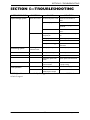
SECTION 5—TROUBLESHOOTING
SYSTEM/OPERATION
Hydromassage System
SYMPTOMS
System will not start
FAULTS
SOLUTION
No electrical power to tub Check and reset breaker or
GFCI.
System not prepared
Be sure water level is above jets.
Check that inlet plug on tub is
depressed.
System is ineffective
Disinfecting System
Tub Operation
No discharge from
disinfectant wand
No water flow
Switch hose disconnected
Reconnect hose to switch and
motor.
Water deposits in
whirlpool jets
Disassemble and clean whirlpool
jets.
Whirlpool jets closed
Open whirlpool jets.
Aerator closed
Open aerator.
Whirlpool intake clogged
Inspect intake and remove
obstruction.
Whirlpool jets open
Close whirlpool jets.
Whirlpool intake open
Close whirlpool intake.
Hose kinked
Inspect hose and unkink.
Disinfectant siphon tube
kinked
Inspect siphon tube and unkink.
Flow meter adjustment
knob turned off
Turn flow meter adjustment knob
to proper setting.
Water supply turned off
Turn on water supply.
Restricted water flow RADA valve. Refer to
RADA owner’s manual.
Inspect and clean RADA valve.
NOTE: If problems are not remedied by the suggested means above, contact an ICCG dealer or technical support.
Part No 1150695
35
Recessed Side Entry Bath Tubs
LIMITED WARRANTY
PLEASE NOTE: THE WARRANTY BELOW HAS BEEN DRAFTED TO COMPLY WITH FEDERAL
LAW APPLICABLE TO PRODUCTS MANUFACTURED AFTER JULY 4, 1975.
This warranty is extended only to the original purchaser/user of our products.
This warranty gives you specific legal rights and you may also have other legal rights which vary from
state to state.
Invacare Continuing Care Group (ICCG) warrants its bathing/whirlpool products to be free from defects
in materials and workmanship for a period of three years from the date of purchase. Warranty obligation
is limited to parts replacement only. Warranty replacement parts are only covered for the duration of
the warranty period. All purchased replacement parts will carry a 30-day warranty from the date of
shipment. If within such warranty period any such product shall be proven to be defective, such product
shall be repaired or replaced, at ICCG's option. This warranty does not include any labor or shipping
charges incurred in replacement part installation or repair of any such product. ICCG's sole obligation
and your exclusive remedy under this warranty shall be limited to such repair and/or replacement.
For warranty service, please contact the dealer from whom you purchased your ICCG product. In the
event you do not receive satisfactory warranty service, please write directly to ICCG at the address
below. Provide dealer's name, address, model number, date of purchase, indicate nature of the defect
and, if the product is serialized, indicate the serial number.
ICCG will issue a return authorization. The defective unit or parts must be returned for warranty
inspection using the serial number, when applicable, as identification within thirty days of return
authorization date. DO NOT return products to our factory without our prior consent. C.O.D.
shipments will be refused; please prepay shipping charges.
LIMITATIONS AND EXCLUSIONS: THE WARRANTY SHALL NOT APPLY TO PROBLEMS
ARISING FROM NORMAL WEAR OR FAILURE TO ADHERE TO THE ENCLOSED INSTRUCTIONS.
LABOR; EXPENDABLE ITEMS, I.E. SHOWER HOSES, VALVES, “O” RINGS, SEALS; PARTS
BROKEN DUE TO ABUSE OR IMPROPER USE; ITEMS THAT BECOME INOPERABLE DUE TO
LACK OF MAINTENANCE, OR NON COMPATIBLE CHEMICALS; STAINS DUE TO HARD WATER,
IODINE SOLUTIONS, OR OTHER UNAPPROVED CHEMICALS; “SPIDER” CRACKS OR
“CRACKING” DUE TO MISHANDLING OR ABUSE. IN ADDITION, THE FOREGOING WARRANTY
SHALL NOT APPLY TO SERIAL NUMBERED PRODUCTS IF THE SERIAL NUMBER HAS BEEN
REMOVED OR DEFACED; PRODUCTS SUBJECTED TO NEGLIGENCE, ACCIDENT, IMPROPER
OPERATION, MAINTENANCE OR STORAGE; OR PRODUCTS MODIFIED WITHOUT ICCG'S
EXPRESS WRITTEN CONSENT INCLUDING, BUT NOT LIMITED TO: MODIFICATION THROUGH
THE USE OF UNAUTHORIZED PARTS OR ATTACHMENTS: PRODUCTS DAMAGED BY REASON
OF REPAIRS MADE TO ANY COMPONENT WITHOUT THE SPECIFIC CONSENT OF ICCG;
PRODUCTS DAMAGED BY CIRCUMSTANCES BEYOND ICCG'S CONTROL; PRODUCTS
REPAIRED BY ANYONE OTHER THAN AN ICCG DEALER, SUCH EVALUATION SHALL BE
SOLELY DETERMINED BY ICCG.
THE FOREGOING EXPRESS WARRANTY IS EXCLUSIVE AND IN LIEU OF ANY OTHER
WARRANTIES WHATSOEVER, WHETHER EXPRESS OR IMPLIED, INCLUDING THE IMPLIED
WARRANTIES OF MERCHANTABILITY AND FITNESS FOR A PARTICULAR PURPOSE, AND THE
SOLE REMEDY FOR VIOLATIONS OF ANY WARRANTY WHATSOEVER, SHALL BE LIMITED TO
REPAIR OR REPLACEMENT OF THE DEFECTIVE PRODUCT PURSUANT TO THE TERMS
CONTAINED HEREIN. THE APPLICATION OF ANY IMPLIED WARRANTY WHATSOEVER
SHALL NOT EXTEND BEYOND THE DURATION OF THE EXPRESS WARRANTY PROVIDED
HEREIN. THE MANUFACTURER SHALL NOT BE LIABLE FOR ANY CONSEQUENTIAL OR
INCIDENTAL DAMAGES WHATSOEVER.
THIS WARRANTY SHALL BE EXTENDED TO COMPLY WITH STATE/PROVINCIAL LAWS AND
REQUIREMENTS.
Invacare Continuing Care Group
www.invacare-ccg.com
USA
One Invacare Way
Elyria, Ohio USA
44036-2125
All rights reserved. Trademarks are
identified by the symbols ™ and ®. All
trademarks are owned by or licensed to
Invacare Corporation unless otherwise
noted.
Canada
994 Hargrieve Rd.
London Ontario
N6E 1P5 Canada
Betadine is a registered trademark of Purdue
Pharma L.P.
©2008 Invacare Corporation
Part No 1150695
For customer service: 800-668-2337
Rev A - 04/08