1
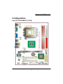
PM945GC (V2.0) Copyright All rights are reserved. No part of this publication may be reproduced, transmitted, transcribed, stored in a retrieval system or translated into any language or computer language, in any form or by any means, electronic, mechanical, magnetic, optical, chemical, manual or otherwise, without the prior written permission of the company. Brands and product names are trademarks or registered trademarks of their respective companies. The vendor makes no representations or warranties with respect to the contents herein and especially disclaim any implied warranties of merchantability or fitness for any purpose. Further the vendor reserves the right to revise this publication and to make changes to the contents herein without obligation to notify any party beforehand. Duplication of this publication, in part or in whole, is not allowed without first obtaining the vendor’s approval in writing. Trademark All the trademarks or brands in this document are registered by their respective owner. Disclaimer We make no warranty of any kind with regard to the content of this user’s manual. The content is subject to change without notice and we will not be responsible for any mistakes found in this user’s manual. All the brand and product names are trademarks of their respective companies. FCC Compliance Statement This equipment has been tested and found to comply with the limits of a Class B digital device, pursuant to Part 15 of the FCC Rules. These limits are designed to provide reasonable protection against harmful interference in a residential installation. This equipment generates, uses and can radiate radio frequency energy and, if not installed and used in accordance with the instructions, may cause harmful interference to radio communications. Operation of this equipment in a residential area is likely to cause harmful interference in which case the user will be required to correct the interference at his own expense. However, there is no guarantee that interference will not occur in a particular installation. CE Mark The device is in accordance with 89/336 ECC-ENC Directive. Ver: EG100 PM945GC (V2.0) Intel® 945GC & ICH7 Support Socket 775 Intel® CoreTM 2 Duo/ Pentium® D/ Pentium® 4/ Celeron® D/ Celeron® Processor (The power consumption for the aforementioned processors must be rated at 65W or less.) User Manual Enabling the Hyper-Threading Technology, your computer system is required to have components as the following: CPU: An Intel® Pentium® 4 Processor with HT Technology Chipset: An Intel® Chipset that supports HT Technology BIOS: A BIOS that supports HT Technology must be enabled OS: An operating system that supports HT Technology For more information on Hyper-Threading Technology, go to: http://www.intel.com/info/hyperthreading Dimensions (Micro-ATX form-factor): 180mm x 244mm ( W x L ) Operating System: Windows® Vista/ XP/ 2000 Things You Have To Know 0 The images and pictures in this manual are for reference only and may vary from the product you received depending on specific hardware models, third party components and software versions. 0 This mainboard contains very delicate IC chips. Always use a grounded wrist strap when working with the system. 0 Do not touch any IC chip, lead, connector or other components. 0 Always unplug the AC power when you install or remove any device on the mainboard or when confuguring pins and switches. Packing List PM945GC(V2.0) Mainboard IDE Cable SATA Cable I/O Bracket Mainboard Setup Driver & User Manual CD Mainboard Quick Installation Guide Symbols Attention- Important Information Follow the procedures below… Troubleshooting Tips Refer to other sections in this manual… Table of Contents CHAPTER 1. GETTING STARTED .................................................... 1 INTRODUCTION ....................................................................................................... 1 SPECIFICATION ....................................................................................................... 2 CONFIGURATION .................................................................................................... 5 Layout of PM945GC (V2.0)............................................................................ 5 HARDWARE INSTALLATION ................................................................................... 6 CPU Processor Installation.............................................................................. 6 Memory Installation: DIMM1/DIMM2........................................................... 7 Back Panel Configuration................................................................................ 9 Front Panel Headers: JW_FP, PWRLED, SPEAK ........................................ 10 Connectors..................................................................................................... 11 Headers & Jumpers........................................................................................ 12 Audio Configuration...................................................................................... 14 Slots ............................................................................................................... 15 Power Supply Attachments............................................................................ 16 CHAPTER 2. BIOS SETUP ........................................................... 17 INTRODUCTION ..................................................................................................... 17 MAIN MENU ......................................................................................................... 18 CHAPTER 3: SOFTWARE SETUP................................................... 20 SOFTWARE LIST ................................................................................................... 20 SOFTWARE INSTALLATION ................................................................................... 20 CHAPTER 4: TROUBLESHOOTING................................................. 24 APPENDIX I: 6/4/2 CHANNEL AUDIO EFFECT SETUP ............................................ 27 Mainboard PM945GC(V2.0) Chapter 1. Getting Started Introduction Thanks for choosing PM945GC(V2.0) Mainboard. It is based on Intel® 945GC Northbridge chipset and Intel® ICH7 Southbridge chipset. In addition, it also supports integrated Graphics Media Accelerator 950 for onboard graphics feature. It supports Intel® CoreTM 2 Duo/ Pentium® D/ Pentium® 4/ Celeron® D/ Celeron® Processors (The power consumption for the aforementioned processors must be rated at 65W or less) with FSB (Front Side Bus) frequencies of 1333 MHz (by overclocking)/ 1066 MHz (by overclocking)/ 800 MHz/ 533 MHz. The PM945GC(V2.0) provides two DIMM (Dual In-Line Memory Modules) sockets which allowing you to install 240-pin, unbuffered non-ECC, DDRII 667 (by overclocking)/ DDRII 533 SDRAMs. It also supports Dual Channel Technology and allows you installing a total memory capacity of 4 GB. This mainboard provides one PCI-Express interface slot up to x16 mode which is recommended that insert a graphics card onto the PCI-Espress x16 slot. In addition, two standard PCI slots for use with standard PCI expansion cards are also allowed. The PM945GC(V2.0) provides one floppy disk drive connector that can be used with 360KB/720KB/1.2MB/1.44MB/2.88MB drives. It also has one IDE connector for IDE hard drives supporting Ultra ATA 100/66/33. Moreover, this mainboard comes with Serial ATA II support with four SATA II connectors which provide up to 3 Gbps data transfer rates. The onboard High Definition Audio CODEC (ALC662) supports high quality performance 6-channel audio play <See Appendix I>. The mainboard also supports the Sony/Philips Digital Interfaces (S/PDIF) output function (optional). The PM945GC(V2.0) also comes with an onboard 10/100 Mbps Ethernet LAN chip. There is a LAN port on the back panel of your case that you can directly plug into an Internet cable. There are maximal eight USB2.0/ 1.1 ports which can be set up on this mainboard. All the information (including hardware installation and software installation) in this manual are for reference only. The contents in this manual may be updated without notice. The company will not assume any responsibility for any errors or mistakes within. 1 Mainboard PM945GC(V2.0) Specification CPU: Support Socket 775 Support Intel® CoreTM 2 Duo/ Pentium® D/ Pentium® 4/ Celeron® D/ Celeron® Processors (The power consumption for the aforementioned processors must be rated at 65W or less.) Support Hyper-Threading Technology Support 1333 MHz (by overclocking)/ 1066 MHz (by overclocking)/ 800 MHz/ 533 MHz FSB (Front Side Bus) Frequencies Chipset: Northbridge Chipset – Intel® 945GC Southbridge Chipset – Intel® ICH7 I/O Controller –Fintek® F71872FG High Definition Audio Codec – Realtek® ALC662 LAN Controller – Marvell® 88E8042 Memory: Two DIMM sockets Supports unbuffered & non-ECC DDRII 667 (by overclocking)/ DDRII 533 SDRAM Supports a total memory capacity of up to 4 GB Supports Dual Channel data bus Onboard HD Audio Codec (ALC 662): High performance Codec with high S/N ratio (>90 db) Supports 6/4/2 channel playback capability Supports jack sensing and re-tasking function Built-in Dolby Digital Live Technology Supports Sony/ Philips Digital Interfaces (S/PDIF) output function (Optional) Slots: One PCI-Express x16 interface slot for graphics card or expansion card Two standard PCI slots for PCI standard expansion cards 2 Mainboard PM945GC(V2.0) FDD Connector: Supports one FDD connector to set up to two floppy disk drives Supports 360KB/ 720KB/ 1.2MB/ 1.44MB/ 2.88MB IDE Connector: One IDE connector Supports up to two IDE devices Supports Ultra ATA 33/66/100 Supports high capacity hard disk drives Serial ATA II Connector: Four SATA II connectors Supports SATA 2.0 specification and with transmit rate up to 3 Gbps One SATA connector can only support one SATA HDD Onboard LAN Chip: 10/100 Mbps Ethernet LAN supported I/O facility Connectors Supports one PS/2 mouse port and one PS/2 keyboard port Supports one serial port Supports one VGA port (=D-Sub) Supports one parallel port(PARALLEL)header and one HDMI-SPDIF OUT (HDMI-SPDIF) header with external devices connected Universal Serial Bus: Four onboard USB 2.0/ 1.1 ports Two front USB headers come with this mainboard for additional four USB ports Support a maximum of eight USB ports to connect USB compliant devices BIOS: Phoenix-Award™ BIOS Support APM1.2 Support ACPI 2.0 power management 3 Mainboard PM945GC(V2.0) Green Function: Supports Phoenix-Award™ BIOS power management function Supports system-wake-from-power-saving-mode by keyboard or mouse touching Shadow RAM: Integrated memory controller provides shadow RAM functionality and supports ROM BIOS Flash Memory: Supports flash memory functionality Supports ESCD functionality Hardware Monitor Function: Monitors CPU/ Chassis Fan Speed Monitors CPU and system temperature Monitors system voltages 4 Mainboard PM945GC(V2.0) Configuration Layout of PM945GC (V2.0) 5 Mainboard PM945GC(V2.0) Hardware Installation This section will assist you in quickly installing your system hardware. Wear a wrist ground strap before handling components. Electrostatic discharge may damage the system’s components. CPU Processor Installation This mainboard supports Intel® CoreTM 2 Duo/ Pentium® D/ Pentium® 4/ Celeron® D/ Celeron® Processors using a Socket 775. Before building your system, we suggest you to visit the Intel website and review the processor installation procedures. http://www.intel.com CPU Socket 775 Configuration Steps: 1. 2. 3. 4. Locate the CPU socket 775 on your mainboard and nudge the lever away from the socket as shown. Then lift the lever to a 140-degree angle (A). Next, lift up the iron cover (B). There are 2 distinctive marks located near the corners of the socket on the same side as the lever as shown (C). Match these marks with the marks on the CPU and carefully lower the CPU down onto the socket (D). A B C D E F Replace the iron cover and then lower the lever until it snaps back into position (E). This will lock down the CPU (F). Smear thermal grease on the top of the CPU. Lower the CPU fan onto the CPU/CPU socket and secure it using the attachments or screws provided on the fan. Finally, attach the fan power cord to the CPUFAN header. Attention DO NOT touch the CPU pins in case they are damaged. Also, make sure that you have completed all installation steps before powered on the system. Finally, double-check that the cooling fan is properly installed and the CPU fan power cord is securely attached, in case your CPU and other sensitive components are damaged because of high temperatures. 6 Mainboard PM945GC(V2.0) FAN Headers: CPUFAN, SYSFAN1, SYSFAN2 There are three fan headers available for cooling fans. The cooling fans play an important role in maintaining ambient temperatures in your system. The CPUFAN header is attached with a CPU cooling fan. The SYSFAN1 and SYSFAN2 headers are attached with other cooling fans. CPUFAN SYSFAN1/ SYSFAN2 Attention You can avoid damaging your CPU due to high temperatures with proper cooling equipment. It is recommended that attach a cooling fan on top of your CPU. Use the CPUFAN header to attach the fan cord. On most fan power cord, the black wire of the fan cable is the “ground” and should be attached to pin-1 of the header. Memory Installation: DIMM1/DIMM2 The PM945GC(V2.0) provides two DIMM (Dual In-Line Memory Modules) sockets which allowing you to install 240-pin, unbuffered non-ECC, DDRII 667 (by overclocking)/ DDRII 533 SDRAMs. It also supports Dual Channel Technology and allows you installing a total memory capacity of 4 GB. Attention It is recommended that to install memories which are identical specifications (same timing specifications and same DDRII speed) to achieve the best effects. It may cause the failure of power-on or lower memory speed if installing different type, SPD (series presence detects) memories. 7 Mainboard PM945GC(V2.0) How to enable Dual-Channel DDRII: 1. These mainboards provide Dual-Channel functionality for the two DIMM sockets. Enabling Dual-Channel can significantly increase your data access rates. DIMM1 and DIMM2 share one channel. 2. For enabling Dual-Channel, you have to install two memories in the DIMM sockets at the same time; according to the definition by Intel, once one channel of the memory capacity is the same with the other channel, then Dual-Channel will be enabled. 3. For example, if you install one 256 MB memory in DIMM1 and the other one in DIMM2 (256MB x 2 = 512MB), so that the Dual-Channel can be enabled. 4. If you only install one memory, then the Dual-Channel won’t be enabled. Memory Installation Steps: 1. Pull the white plastic tabs at both ends of the slot away from the slot. 2. Match the notch on the RAM module with the corresponding pattern in the DIMM slot. This will ensure that the module will be inserted with the proper orientation. 3. Lower the RAM module into the DIMM Slot and press firmly using both thumbs until the module snaps into place. 4. Repeat steps 1, 2 & 3 for the remaining RAM modules. * The pictures above are for reference only. Your actual installation may vary slightly from the pictures. 8 Mainboard PM945GC(V2.0) Back Panel Configuration PS/2 Mouse & PS/2 Keyboard Ports: KB/MS This mainboard provides a standard PS/2 mouse port and a PS/2 keyboard port. The Serial Port: COM1 This mainboard provides a serial port COM1 on your back panel, and is used to connect mice, modem and other peripheral devices. Through this port, you can also transfer data from your computer hard disk drive to other computers. The VGA (D-SUB) Connector: VGA The mainboard provides one VGA connector (= D-Sub connector) on back panel. VGA connector (= D-Sub connector) delivers the analogy signals, and is able to connect with traditional CRT display, flat display, or other display device which with the D-Sub interface compatible. USB Ports/LAN Port: USB1, USB/LAN There are four onboard USB 2.0/ 1.1 ports on the back panel. These USB ports are used to attach with USB devices, such as keyboard, mice and other USB supported devices. There is also a 10/100 Mbps Ethernet LAN port available for you to attach an Internet cable. 9 Mainboard PM945GC(V2.0) Audio Ports: SOUND This mainboard provides three audio ports, the Mic, Line-in and Line-out. These are the standard audio ports that provide basic audio function. Line-In (Blue) This port is for audio input and connects to external audio devices such as CD player, tape player, etc. When the multi-channel audio system is enabled, this port will output audio for the rear speakers. Line-Out (Green) This port is an output audio port used for connecting to speakers or a headset. When the multi-channel audio system is enabled, this port will output audio for the front speakers. Mic-In (Pink) This port is for connecting to a microphone. When the multi-channel audio system is enabled, this port will output audio for your subwoofer/center speakers. This mainboard supports Super 5.1 Channel Audio Effect, and you can transfer 2-channel to 6-channel audio. See Appendix I for more information. Front Panel Headers: JW_FP, PWRLED, SPEAK JW_FP Pin 1 3 5 7 9 Assignment VCC5 (+) HDDLE (-) GND RSTSW N/C Function Hard Drive LED (HDLED) Reset Switch (RESET) 10 Pin Assignment Function 2 4 6 8 10 VCC5 (+) PWRLED (-) PWRBTN GND 2-pin Power LED (PWR LED) Power-on Button (PWRBTN) Key Mainboard PM945GC(V2.0) Hard Drive LED Header: HDLED If your case front panel has a hard drive LED cable, attach it to this header. The LED will flicker when there is hard disk drive activity. Reset Switch Header: RESET This header can be attached to a momentary SPST switch (reset button) cable on your case front panel. The switch is normally left open. When the switch closed, it will cause the mainboard to reset and run the POST (Power-On Self Test). Power-on Switch Header: PWRBTN This header can be attached to a power switch cable on your case front panel. You can turn your system on or off by pressing the button attached to this power switch cable. 2-pin Power LED Header: PWR LED These mainboards provide a 2-pin power LED header. If there is a 2-pin power LED cord on your case front panel, you can attach it to the 2-pin power LED header. Then the power LED will illuminate while the system is powered on. 3-pin Power LED Header: PWRLED These mainboards also provide a 3-pin power LED header. If there is a 3-pin power LED cord on your case front panel, you can attach it to this 3-pin header instead of attach to the 2-pin one on the SW/LED header. PWRLED Pin Assignment Pin Assignment 1 PWR_LED (+) 2 Key 3 PWR_LED (-) Speaker Header: SPEAK A speaker cable on your case front panel can be attached to this header. When you reboot the computer, this speaker will issue a short audible (beep). If there are problems during the Power On Self-Test, the system will issue an irregular pattern of audible beeps through this speaker. SPEAK Pin 1 3 Assignment SPK Ground Pin 2 4 Assignment N/C VCC5 Connectors Floppy Disk Drive Connector: FLOPPY These mainboards provide a standard floppy disk drive connector (FDD) that supports 360KB/ 720KB/ 1.2MB/ 1.44MB/ 2.88 MB floppy disk drives using a FDD ribbon cable. 11 Mainboard PM945GC(V2.0) Hard Disk Drive Connectors: IDE1 The mainboards provide one IDE connector that supports Ultra ATA 33/66/100 IDE devices. You can attach a maximum of two IDE devices, such as hard disk drive (HDD), CD-ROM, DVD-ROM, etc. using an IDE ribbon cable. In general, two IDE devices can be attached onto one IDE connector. If you attach two IDE HDDs, you must configure one drive as the master and the other one as the slave. In this case, one optical device i.e., CD-ROM, DVD-ROM…etc. should be attached to this connector as well. SATA II Connector: SATA 1/2/3/4 The four SATA II connectors support 3 Gbps transmit rate, and one SATA connector only can attach one SATA HDD of each time using SATA cables. Attention The FDD/ IDE cable is designed and should be attached with a specific direction. One edge of the cable will usually in color such as red, to indicate that should line up with the header pin-1. Headers & Jumpers Front USB Headers: USB2/3 These mainboards provide four onboard USB 1.1/2.0 ports (back panel) that attach to USB devices. There are two additional USB headers that can be connected by cables to four more USB ports on the front panel of your case giving you a possible eight USB ports. USB2/3 Pin 1 3 5 7 9 Assignment VCC -DATA +DATA GND Key Pin 2 4 6 8 10 Assignment VCC -DATA +DATA GND N/C Attention If you are using a USB 2.0 device with Windows 2000/XP, you will need to install the USB 2.0 driver from the Microsoft® website. If you are using ® Service pack 2 (or later) for Windows XP, and using Service pack4 (or later) for Windows® 2000, you will not have to install the driver. 12 Mainboard PM945GC(V2.0) Printer Interface Header: PARALLEL (Optional) This mainboard provides a PARALLEL header for you connecting an additional printer connector on your case back panel. Attach the cable of printer connector (Optional) onto this header, and then you can use the printer connector connecting with a printer. Keyboard/Mouse & USB Power On function Header: JP1 PS/2 Keyboard and PS/2 Mouse attached to the back panel can awaken the system from sleep mode. In order to enable this functionality, you must adjust the jumper caps on JP1 header as the table below. JP1 1 1 Assignment KB/MS & USB Power ON Disable (Default) Pin 1-2 Closed KB/MS & USB Power ON Enabled Pin 2-3 Closed Note: Close stands for putting a jumper cap onto two header pins. USB Power On function Header: JP3 USB devices attached to the back panel USB ports can awaken the system from sleep mode. In order to enable this functionality, you must adjust the jumper cap on JP3 header for +5V or +5VSB mode depending on which USB port that the USB device is attached to. JP3 Pin 1-2 Closed Pin 2-3 Closed Assignment +5V +5VSB Assignment USB Power On Disable (Default) USB Power On Enabled Note: Close stands for putting a jumper cap onto two header pins. 13 Mainboard PM945GC(V2.0) Clear CMOS Jumper: JBAT The “Clear CMOS” function is used when you are unable boot your system and need to reset the BIOS settings (CMOS settings) back to the manufacturer’s original settings. This is also a way to reset the system password if you have forgotten it. JBAT Assignment Pin 1-2 Closed Normal (Default) Pin 2-3 Closed Clear CMOS Data Note: Close stands for putting a jumper cap onto two header pins. The following steps explain how to reset your CMOS configurations when you forgot a system password. 1. Turn off your system and disconnect the AC power cable. 2. Set JBAT header to OFF (2-3 Closed). 3. Wait several seconds. 4. Set JBAT header to ON (1-2 closed). 5. Connect the AC power cable and turn on your system. 6. Reset your new password. Audio Configuration CD-ROM Audio-In Connector: CDIN The CD-IN connector is used to attach an audio cable to audio devices such as CD-ROMs, DVD-ROMs etc. HDMI-SPDIF out Header: HDMI_SPDIF (Optional) The SPDIF output is capable of providing digital audio to external speakers or compressed AC3 data to an external Dolby digital decoder. Use the feature only when your stereo system has digital input function. HDMI_SPDIF Pin 1 Assignment Pin 2 HDMI_SPDIF_OUT 14 Assignment GND Mainboard PM945GC(V2.0) Front Panel Audio Header: AUDIO If your case front panel has audio ports, you can connect them to the Front Audio Header of this mainboard. Pin 1 3 5 7 9 Assignment MIC2-L MIC2-R LINEOUT2-R SENSE-FB LINEOUT2-L AUDIO Pin 2 4 6 8 10 Assignment AUD_GND AUD_JD AUD_GND N/C AUD_GND Slots Universal PCI-Express Interface slot: PE2 The PE2 slot is the PCI-Express interface slot which can be supported up to PCI-E x16 mode. It is recommended that you insert a graphics card onto the PE2 slot which the interface is capable for PCI-E x16 specification. PCI Interface Slots: PCI1/2 PCI stands for Peripheral Component Interconnect, which is a bus standard for installing expansion cards such as network card, SCSI card, etc. to these PCI slots. 15 Mainboard PM945GC(V2.0) Power Supply Attachments ATX Power Connector: ATXPWR, ATX12V These mainboards provide two ATX power connectors, one 24-pin ATXPWR connector and one 4-pin ATX12V connector. You must use a power supply that has both of these connectors and both connectors must be attached before the system is powered on. These power connectors support several power management functions such as the instant power-on function. The connector pins are described below. ATXPWR ATX12V Pin Assignment Pin Assignment 1 2 3 4 5 6 7 8 9 10 11 12 +3.3V +3.3V Ground +5V Ground +5V Ground PW_ON +5V standby voltage +12V +12V +3.3V 13 14 15 16 17 18 19 20 21 22 23 24 +3.3V -12V Ground Soft Power ON Ground Ground Ground -5V +5V +5V +5V Ground Pin Assignment Pin Assignment 1 2 Ground Ground 3 4 +12V +12V Attention In general, power cords are designed and should be attached with a specific direction. The black wire of the power cord is Ground and should be attached onto the header location of Ground. 16 Mainboard PM945GC(V2.0) Chapter 2. BIOS Setup Introduction This section describes PHOENIX-AWARD™ BIOS Setup program which resides in the BIOS firmware. The Setup program allows users to modify the basic system configuration. The configuration information is then saved to CMOS RAM where the data is sustained by battery after power-down. The BIOS provides critical low-level support for standard devices such as disk drives, serial ports and parallel ports. As well, the BIOS control the first stage of the boot process, loading and executing the operating system. The PHOENIX-AWARDTM BIOS installed in your computer system’s ROM is a custom version of an industry standard BIOS. This means that it supports the BIOS of Intel® based processors. This version of the PHOENIX-AWARDTM BIOS includes additional features such as virus and password protection as well as special configurations for fine-tuning the system chipset. The defaults for the BIOS values contained in this document may vary slightly with the version installed in your system. Key Function In general, you can use the arrow keys to highlight options, press <Enter> to select, use the <PgUp> and <PgDn> keys to change entries, press <F1> for help and press <Esc> to quit. The following table provides more detail about how to navigate within the BIOS Setup program. Keystroke Function Up arrow Move to previous option Down arrow Move to next option Left arrow Move to the option on the left (menu bar) Right arrow Move to the option on the right (menu bar) Esc Main Menu: Quit without saving changes Submenus: Exit Current page to the next higher level menu Move Enter Move to the option you desire PgUp key Increase the numeric value or enter changes PgDn key Decrease the numeric value or enter changes + Key Increase the numeric value or enter changes - Key Decrease the numeric value or enter changes Esc key Main Menu – Quit and do not save changes into CMOS Status Page Setup Menu and Option Page Setup Menu – Exit Current page and return to Main Menu F1 key General help on Setup navigation keys F5 key Load previous values from CMOS F6 key Load the defaults from BIOS default table F7 key Load the turbo defaults F10 key Save all the CMOS changes and exit 17 Mainboard PM945GC(V2.0) Main Menu Standard CMOS Features Include all the adjustable items in standard compatible BIOS. Advanced BIOS Features Include all the adjustable items of Award special enhanced features. Advanced Chipset Features Include all the adjustable items of chipset special features. Integrated Peripherals Include all onboard peripherals. Power Management Setup Include all the adjustable items of Green function features. PnP/PCI Configurations Include all configurations of PCI and PnP ISA resources. 18 Mainboard PM945GC(V2.0) PC Health Status It is for monitoring the system status such as temperature, voltage, and fan speeds. Miscellaneous Control It is for you to specify settings for Miscellaneous Control, such as the CPU clock and frequency ratio. Load Optimized Defaults It can load the preset system parameter values to set the system in its best performance configurations. Load Standard Defaults It can load the preset system parameter values to set the system in its stable performance configurations. Set Supervisor Password Set change or disable password. It allows you to limit access to the system and/or BIOS setup. Set User Password Set change or disable password. It allows you to limit access to the system. Save & Exit Setup Save CMOS value settings to CMOS and exit setup. Exit Without Saving Abandon all CMOS value changes and exit setup. 19 Mainboard PM945GC(V2.0) Chapter 3: Software Setup Software List Category Platform ® Windows Vista/ XP/ 2000 Intel Chipset INF ® Windows Vista/ XP/ 2000 Marvell Lan Driver ® Windows Vista/ XP/ 2000 Realtek Audio Driver ® Windows Vista/ XP/ 2000 Intel VGA Driver ® Windows XP/ 2000 Microsoft DirectX9.0c Attention You don’t need to install the driver for USB 2.0 version if you are using Windows® XP with Service Pack 2 (or more advanced), or Windows® 2000 with Service Pack 4 (or more advanced). Software Installation Place the Driver CD into the CD-ROM drive and the Installation Utility will auto-run. You can also launch the Driver CD Installation Utility manually by executing the Intel.exe program located on the Driver CD. (For more details, please refer to the Readme.txt files that in each folder of the Driver.) ◎ 1. The screen and images are only for general reference. The version of the screens you received with your software may vary slightly. When you insert the driver CD into the CD-ROM, you’ll see the screen as the picture below. There are several driver buttons displayed in the “Driver Menu” screen, and you can click on the drivers to install. 20 Mainboard PM945GC(V2.0) For Windows Vista Driver For Windows XP (64bit) Driver Attention Before you install the Realtek Audio Driver on Windows® XP (64bit) operating system, please go to the Microsoft® website to install the update for enabling HD Audio. 21 Mainboard PM945GC(V2.0) For Windows XP (32bit) Driver For Windows 2000 Driver 22 Mainboard PM945GC(V2.0) 2. Intel Chipset INF – It provides all drivers for the functions which built in both the Northbridge/ Southbridge. Intel VGA Driver – It provides the driver of Intel VGA. Marvell LAN Driver – It provides the driver of Marvell Network. Realtek Audio Driver – It provides the driver of Realtek Audio CODEC. Microsoft DirectX 9.0c – It provides the software of Microsoft DirectX 9.0c. Click on the “User Manual” button, you can choose the manual to read. Attention: Before you read manuals, you must install the driver of Adobe Acrobat Reader 6 to browse PDF files. 3. If you click the “Browse CD” button, you can browse all the files in the Driver CD. 23 Mainboard PM945GC(V2.0) Chapter 4: Troubleshooting Problem 1: No power to the system. Power light does not illuminate. Fan inside power supply does not turn on. Indicator lights on keyboard are not lit. Causes: 1. Power cable is unplugged. 2. Defective power cable. 3. Power supply failure. 4. Faulty wall outlet; circuit breaker or fuse blown. Solutions: 1. Make sure power cable is securely plugged in. 2. Replace cable. 3.Contact technical support. 4.Use different socket, repair outlet, reset circuit breaker or replace fuse. Problem 2: System inoperative. Keyboard lights are on, power indicator lights are lit, hard drive is active but system seems “hung” Causes: Memory DIMM is partially dislodged from the slot on the mainboard. Solutions: 1. Power Down 2. Using even pressure on both ends of the DIMM, press down firmly until the module snaps into place. Problem 3: System does not boot from the hard disk drive but can be booted from the CD-ROM drive. Causes: 1. Connector between hard drive and system board unplugged. 2. Damaged hard disk or disk controller. 3. Hard disk directory or FAT is corrupted. Solutions: 1. Check the cable running from the disk to the disk controller board. Make sure both ends are securely attached. Check the drive type in the standard CMOS setup. 2. Contact technical support. 3. Backing up the hard drive is extremely important. Make sure your periodically perform backups to avoid untimely disk crashes. Problem 4: System only boots from the CD-ROM. The hard disk can be read and applications can be used but booting from the hard disk is impossible. Causes: Hard Disk boot sector has been corrupted. 24 Mainboard PM945GC(V2.0) Solutions: Back up data and applications files. Reformat the hard drive. Re-install applications and data using backup disks. Problem 5: Error message reading “SECTOR NOT FOUND” displays and the system does not allow certain data to be accessed. Causes: There are many reasons for this such as virus intrusion or disk failure. Solutions: Back up any salvageable data. Then performs low level format, partition, and then a high level format the hard drive. Re-install all saved data when completed. Problem 6: Screen message says “Invalid Configuration” or “CMOS Failure.” Causes: Incorrect information entered into the BIOS setup program. Solutions: Review system’s equipment. Reconfigure the system. Problem 7: The Screen is blank. Causes: No power to monitor. Solutions: Check the power connectors to the monitor and to the system. Problem 8: Blank screen. Causes: 1. Memory problem. 2. Computer virus. Solutions: 1. Reboot computer. Reinstall memory. Make sure that all memory modules are securely installed. 2. Use anti-virus programs to detect and clean viruses. Problem 9: Screen goes blank periodically. Causes: Screen saver is enabled. Solutions: Disable screen saver. Problem 10: Keyboard failure. Causes: Keyboard is disconnected. Solutions: Reconnect keyboard. Replace keyboard if you continue to experience problems. 25 Mainboard PM945GC(V2.0) Problem 11: No color on screen. Causes: 1. Faulty Monitor. 2. CMOS incorrectly set up. Solutions: 1. If possible, connect monitor to another system. If no color appears, replace monitor. 2. Call technical support. Problem 12: The screen displays “C: drive failure.” Causes: Hard drive cable not connected properly. Solutions: Check hard drive cable. Problem 13: Cannot boot the system after installing a second hard drive. Causes: 1. Master/slave jumpers not set correctly. 2. Hard drives are not compatible / different manufacturers. Solutions: 1. Set master/slave jumpers correctly. 2.Run SETUP program and select the correct drive types. Call drive manufacturers for possible compatibility problems with other drives. Problem 14: Missing operating system on hard drive. Causes: CMOS setup has been changed. Solutions: Run setup and select the correct drive type. Problem 15: Certain keys do not function. Causes: Keys jammed or defective. Solutions: Replace keyboard. 26 Mainboard PM945GC(V2.0) Appendix I: 6/4/2 Channel Audio Effect Setup Channels Setup 1. 2. 3. 4. After into the system, click the audio icon from the Windows screen. Click “Audio I/O” button, you can see the screen like the picture below. You can choose 2, 4, 6 or 8 channels by your speakers. You can click the “Auto test” button to test your audio devices. To take advantage of 6 Channel Audio Effects, you must use audio software that supports this functionality. You must also make sure your software is specifically configured for 6 Channel Audio Effect support. 27