1
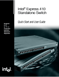
Intel NetStructure™
470 Switch
®
Intel ® NetStructure™ 470 Switch
User Guide
A18558-002
User Guide
Copyright © 2001, Intel Corporation. All rights reserved.
Intel Corporation, 5200 NE Elam Young Parkway, Hillsboro OR 97124-6497
Intel Corporation assumes no responsibility for errors or omissions in this manual. Nor does Intel make any commitment to update the
information contained herein. Intel is a trademark or registered trademark of Intel Corporation or its subsidiaries in the United States and
other countries.
* Other product and corporate names may be trademarks of other companies and are used only for explanation and
to the owners’ benefit, without intent to infringe.
Second Edition
June 2001
A18558-002
C
O
N
T
E
N
T
S
Contents
Intel® NetStructure
470T and 470F Switches User Guide
1 Setting up the Intel® NetStructure™ 470T and
470F Switches
Overview .......................................................................... 1
Management .................................................................... 1
Switch Features ............................................................... 2
LEDs ................................................................................ 3
Connection Guidelines ..................................................... 4
Straight-through vs. Crossover Cables ............................ 4
2 Using the Intel® NetStructure™ 470T and 470F
Switches
Overview .......................................................................... 7
Sample Configuration ...................................................... 8
Flow Control ..................................................................... 9
Broadcast Storm Control .................................................. 9
Spanning Tree Protocol ................................................... 10
Tagged Frames................................................................ 11
Priority Tagging ................................................................ 11
Link Aggregation .............................................................. 12
Virtual LANs ..................................................................... 13
GARP VLAN Registration Protocol (GVRP) ..................... 17
Internet Group Management Protocol (IGMP) ................. 18
3 Using Intel® Device View
Overview .......................................................................... 19
Installing Intel Device View .............................................. 20
Starting Intel Device View ................................................ 21
Installing a New Switch .................................................... 22
Using the Device Tree ..................................................... 22
Managing a Switch ........................................................... 25
Viewing RMON Information ............................................. 25
i
C
O
N
T
E
N
T
S
Intel® NetStructure
470T and 470F Switches User Guide
4 Using the Web Device Manager
Overview .......................................................................... 27
Accessing the Web Device Manager ............................... 28
Navigating the Web Device Manager ............................... 28
Using Management Screens ............................................ 29
Configuring the Switch’s IP Settings ................................ 31
Configuring a Port ............................................................ 32
Managing User Accounts ................................................. 33
Configuring VLANs .......................................................... 35
Link Aggregation .............................................................. 41
Static MAC Addresses ..................................................... 41
Setting Up Priority Tagging .............................................. 43
Configuring Community Strings and Trap Receivers ....... 44
Monitoring Switch Activity ................................................ 45
Viewing/Changing Switch Information .............................. 46
Updating Switch Firmware ............................................... 47
Saving Configuration Changes and Logging Out ............. 48
5 Using Local Management
Overview .......................................................................... 49
Accessing Management ................................................... 49
Logon Screen .................................................................. 50
Navigation ........................................................................ 51
Main Menu (Top Screen) ................................................. 52
Configure Device ............................................................. 53
IP Settings ....................................................................... 54
Port Settings .................................................................... 55
Flow Control ..................................................................... 56
Priority .............................................................................. 56
Configure GBIC Ports (470T only) ................................... 57
Priority Tagging ................................................................ 58
Switch Settings ................................................................ 59
Configure Advanced Switch Settings ............................... 60
Configure Spanning Tree Protocol ................................... 61
Configure Spanning Tree for Ports .................................. 63
Forwarding and Filtering .................................................. 64
ii
C
O
N
T
E
N
T
S
Intel® NetStructure
470T and 470F Switches User Guide
Configure IGMP Snooping ............................................... 65
Configure Static MAC Addresses ..................................... 66
Configure Port Security .................................................... 67
Configure MAC Address Filtering ..................................... 68
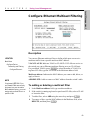
Configure Ethernet Multicast Filtering .............................. 69
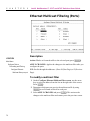
Ethernet Multicast Filtering (Ports) ................................... 70
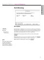
Port Mirroring ................................................................... 71
Link Aggregation .............................................................. 72
Broadcast Storm Control ................................................. 73
Configure Management Menu ......................................... 74
Community Strings & Trap Receivers .............................. 75
Administer User Accounts ................................................ 76
Managing User Accounts ................................................. 78
Define IP Access List ....................................................... 80
Update Firmware and Config Files ................................... 81
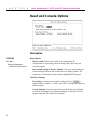
Reset and Console Options ............................................. 82
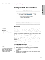
Configure VLAN Operation Mode .................................... 83
Port-based VLANs ........................................................... 84
Add a Port-based VLAN ................................................... 85
Edit/Delete a Port-based VLAN........................................ 86
Change Port Membership in a VLAN ............................... 87
Configure 802.1Q VLANs ................................................ 88
Add an IEEE 802.1Q VLAN
(Configure Port Membership) .............................. 89
Add an IEEE 802.1Q VLAN (Configure Port Tagging) ..... 90
Configuring 802.1Q VLANs .............................................. 91
Edit/Delete an 802.1Q VLAN ........................................... 93
Edit an IEEE 802.1Q VLAN (Configure Membership) ...... 94
Edit an IEEE 802.1Q VLAN (Configure Port Tagging) ..... 95
Configure VLAN ID for Untagged Traffic .......................... 96
GVRP and Ingress Filter Settings .................................... 97
Configure a Protocol-based VLAN ................................... 98
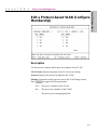
Add a Protocol-based VLAN ............................................ 99
Edit/Delete a Protocol-based VLAN ................................. 100
Edit a Protocol-based VLAN (Configure Membership) ..... 101
iii
C
O
N
T
E
N
T
S
Intel® NetStructure
470T and 470F Switches User Guide
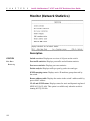
Monitor (Network Statistics) ............................................. 102
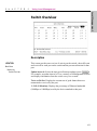
Switch Overview .............................................................. 103
Port Traffic Statistics ........................................................ 104
Port Error Statistics .......................................................... 106
Packet Analysis ................................................................ 108
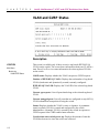
IGMP Snooping Status .................................................... 109
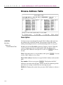
Browse Address Table ..................................................... 110
VLAN and GVRP Status .................................................. 112
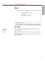
Tools ................................................................................ 113
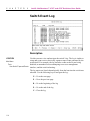
Switch Event Log ............................................................. 114
Ping a Device ................................................................... 115
Upload Configuration Image File ...................................... 116
Save Settings ................................................................... 117
iv
Appendix A: Technical Information
119
Index
139
Intel Customer Support
146
1
Setting up the Intel®
NetStructure™ 470T
and 470F Switches
Overview
This guide provides information on configuring and managing the Intel®
NetStructure™ 470T and 470F Switches. It is organized into five chapters:
• Chapter 1 - Identifying and connecting the switch hardware
• Chapter 2 - Using the switch in a LAN; advanced features such as link
aggregation and VLANs
• Chapter 3 - Using Intel Device View
• Chapter 4 - Using Web Device Manager
• Chapter 5 - Using Local Management
Management
Through the switch’s built-in management you can configure the device and
monitor network health. You can use any combination of the following
methods to manage the switch.
• SNMP management applications like Intel Device View, LANDesk®
Network Manager, HP OpenView*, and IBM Tivoli NetView* are
tailored for Intel products and show a graphical representation of the
device.
• Onboard management allows control over the switch without using an
SNMP application. The Web Device Manager provides a graphical
interface while Local Management is a menu-driven interface.
• Other SNMP-compliant applications can manage the switches if you
compile the switch’s MIB files into that application.
1
C
H
A
P
T
E
R
1
Intel® NetStructure™ 470T and 470F Switches User Guide
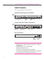
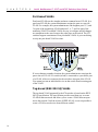
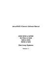
Switch Features
These are the major features of the 470 switches.
8-port 470F Switch (Product Code ES470F)
Status
LED
Link/Activity LEDs
Serial
Port
1000 Base-SX
Port
6+2-port 470T Switch (Product Code ES470T)
Status
LED
Speed LEDs
(top row)
Link/Activity LEDs
(bottom row)
Serial
Port
1000 Base-T
Port
GBIC Port
Back of 470 Switch
MAC
Address
AC Power
Plug
• 100/1000 Base-T auto-negotiates speed, duplex, and flow control—100Mbps or
1000Mbps per port
• 470F supports 1000SX, 1000LX, and 1000LH GBICs
• Half-duplex and full-duplex flow control
• Port settings can be configured manually through management
• Access menu-driven Local Management through the serial port or a Telnet session
• Access the graphical Web Device Manager through a Web browser
2
C
H
A
P
T
E
R
1
Setting Up the Intel® NetStructure™ 470T and 470F Switches
470 Switch Setup
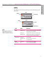
LEDs
The LEDs to the left of the ports indicate port status, individual port speed,
and activity.
470F
Status
Link/Activity
470T
Status
Speed
Link/Activity
NOTE
After the switch is turned on, the
Status LED blinks green once
before the diagnostic mode starts.
LED
State
Meaning
Status
Blinking green
Switch is performing diagnostics and booting.
(This lasts for 20–30 seconds.)
Solid green
Diagnostics have passed, the switch is ready.
Blinking green
Diagnostics have failed. (After the initial 20–
30 seconds, the LED continues blinking.)
Link/Activity
Speed
(470T only)
Solid green
Device linked.
Blinking green
Receiving activity on that port.
Off
No link detected.
Solid green
Off
Device connected at 1000Mbps.
Device connected at 100Mbps.
3
C
H
A
P
T
E
R
1
Intel® NetStructure™ 470T and 470F Switches User Guide
Connection Guidelines
General
• The 470T switch is can auto-negotiate port duplex. It can operate at
half-duplex or full-duplex at 100Mbps, and full-duplex at 1000Mbps.
The switch matches the highest possible speed (up to 1000Mbps) of an
attached device.
• The 470F operates at full-duplex and at 1000Mbps.
Cabling
NOTE
Use certified Category 5 cables to
connect 1000Mbps devices to the
switch.
• Use Category 5 unshielded, twisted-pair (CAT 5 UTP) cable to connect
1000Mbps or 100Mbps devices to the switch.
• Limit the cable length between devices to 100 meters (330 feet) for
copper wire.
• Use a straight-through cable to connect the switch to a server or
workstation.
• To connect to another switch or hub, use a crossover cable.
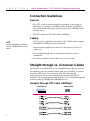
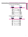
Straight-through vs. Crossover Cables
Switch ports are wired MDI-X, so use a straight-through cable to connect to
a workstation or server (network adapter cards are wired MDI). To connect
to another MDI-X port, use a crossover cable. The following pin
arrangements are for the switch’s Ethernet port and the typical RJ-45
connector. The wiring diagrams illustrate how to wire a straight-through and
crossover cable for 100Mbps and 1000Mbps devices.
Straight-Through UTP cable (100Mbps)
Switch (MDI-X)
4
Adapter (MDI)
C
H
A
P
T
E
R
1
Setting Up the Intel® NetStructure™ 470T and 470F Switches
470 Switch Setup
Crossover UTP cable (100Mbps)
Switch (MDI-X)
Hub (MDI-X)
Straight-Through UTP cable (1000Mbps)
Switch (MDI)
Switch (MDI)
5
C
6
H
A
P
T
E
R
1
Intel® NetStructure™ 470T and 470F Switches User Guide
2
Using the Intel®
NetStructure™ 470T
and 470F Switches
Overview
Chapter 2 provides an overview for using the Intel® NetStructure™ 470T
and 470F Switches within a network. This chapter covers switching features
like flow control and spanning tree, and includes a discussion of the more
advanced features such as link aggregation and the types of VLANs
available on the switch.
If you are familiar with switching technology you can skip ahead to a
particular section within the chapter. The following list shows where you
can find particular topics:
• Sample Configuration page 8
• Flow Control page 9
• Broadcast Storm Control page 10
• Spanning Tree Protocol page 11
• Tagged Frames page 12
• Priority Tagging page 12
• Link Aggregation page 13
• Virtual LANs page 14
• GVRP page 18
• Internet Group Management Protocol (IGMP) Snooping page 18
7
C
H
A
P
T
E
R
2
Intel® NetStructure™ 470T and 470F Switches User Guide
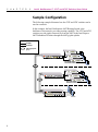
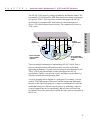
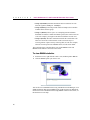
Sample Configuration
The following example illustrates how the 470T and 470F switches can be
used in a network.
In this example, the Intel NetStructure 480T Routing Switch is the
backbone of the network, providing routing capability. The 470T and 470F
switches provide gigabit connectivity from the 480T to the Intel Express
460T Standalone Switches through the 460T gigabit uplinks.
100Mbps
1000Mbps
Link Aggregation
group
Intel® NetStructure™ 470T Switch
Intel Express 460T
Standalone Switches
Intel® NetStructure™ 470F Switch
Intel Express 460T
Standalone Switches
Intel® NetStructure™ 480T Routing Switch
8
Servers
C
H
A
P
T
E
R
2
Using the Intel® NetStructure™ 470T and 470F Switches
Flow Control
During heavy network activity, the switch’s port buffers can receive too
much traffic and fill up faster than the switch can send the information. In
cases like this, the switch tells the transmitting device to wait until the
information in the buffer can be sent. This traffic control mechanism is
called flow control.
• If a port operates at half-duplex, the switch sends a collision (also called
backpressure) that causes the transmitting device to wait.
• If the port operates at full-duplex, the switch sends out an IEEE 802.3x
PAUSE frame.
You can enable or disable flow control for each port on the 470 switch.
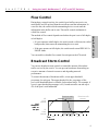
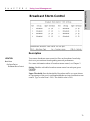
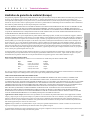
Broadcast Storm Control
You can use broadcast storm control to control the amount of broadcast
traffic serviced by the switch. You can prevent broadcasts from taking an
excessive amount of network resources and degrading network
performance.
To control the amount of broadcast traffic, set an upper threshold
percentage for each port. The upper threshold is the percentage of the
port’s total bandwidth that is available for broadcast traffic. For example, if
a port’s upper threshold percentage is 4%, broadcast traffic can take up to
4% of the port’s total bandwidth.
% of
Broadcast
traffic on
the port
Broadcast traffic
dropped
4%
Upper
threshold
Broadcast traffic
resumed
1%
Lower
threshold
40 s.
Time
in seconds
80 s.
120 s.
160 s.
9
Using the 470 Switch
The method of flow control depends on whether the port is set to full-duplex
or half-duplex.
C
H
A
P
T
E
R
2
Intel® NetStructure™ 470T and 470F Switches User Guide
The switch checks the amount of broadcast traffic on each port every 20
seconds. If the port detects that the amount of broadcast traffic exceeds the
upper threshold on two subsequent checks, the port drops all broadcast
traffic.
When broadcast traffic is dropped for storm control, the switch continues
to check the amount of broadcast traffic on each port. For the port to begin
accepting broadcast traffic again, the amount of broadcast traffic must fall
below the lower threshold percentage. The lower threshold percentage, 1%,
is a factory default. If broadcast traffic falls below the lower threshold
percentage when the port is checked, the switch automatically resumes
servicing broadcast traffic.
When broadcast traffic servicing resumes, the switch begins checking the
amount of broadcast traffic against the upper threshold.
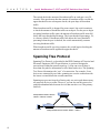
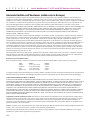
Spanning Tree Protocol
Spanning Tree Protocol, as described in the IEEE (Institute of Electrical and
Electronic Engineers) 802.1D specification, is a protocol designed to
prevent loops within the network topology. A loop can occur if there is
more than one path for information to travel between devices. The Spanning
Tree Protocol determines the “cost” of a connection. For example, if two
devices are connected by two links, spanning tree uses the connection with
the lowest cost and blocks the second connection.
Spanning tree prevents loops by allowing only one active path between any
two network devices at a time. However, you can also use this protocol to
establish redundant links between devices that can take over if the primary
link fails.
Switch B
Backup Path from Client A to Server B:
Switch A –> Switch B –> Switch C
00
th
:1
00
Co
:2
st
st
Pa
2
Co
:
th
:3
Pa
Switch A
Switch C
Path: 1
Cost: 100
PC Client A
Server B
Primary Path from Client A to Server B: Switch A –> Switch C
10
C
H
A
P
T
E
R
2
Using the Intel® NetStructure™ 470T and 470F Switches
In this example, Client A can communicate with Server B over two different
paths. The primary path is Path 1 because the cost of the connection
between switches A and C is lower than the cost between switches A, B and
C. If the primary path fails, traffic is automatically sent over the backup
path.
Tagged Frames
Some devices don’t recognize the tagged Ethernet frames. These devices see
a frame that is too big, and then discard it. When operating 802.1Q (tagbased) VLANs, you can configure the switch to work with untagged
devices. For more information, see “How to configure 802.1Q VLANs” in
Chapter 5.
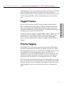
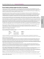
Priority Tagging
The IEEE 802.1D (1998 Edition) specification incorporates IEEE 802.1p
and defines information in the frame tag to indicate a priority level. When
these tagged packets are sent out on the network, the higher priority packets
are transferred first. Priority tagging (also known as Traffic Class
Expediting) is usually set on the LAN adapter in a PC or switch and works
with other elements of the network (switches, routers) to deliver packets
based on priority. The priority level can range from 0 (low) to 7 (high).
The 470 switches can read the priority tags and forward traffic on a per port
basis. The switches have two priority queues per port and queue the packet
based on its priority level. For example, when a packet comes into a switch
with a high-priority tag, the switch inserts the packet in its high-priority
queue.
11
Using the 470 Switch
The 802.1D (1998 Edition) and 802.1Q specifications published by the
IEEE extended Ethernet functionality to add tag information to Ethernet
frames and propagate these tagged frames between bridges. The tag can
carry priority information, VLAN information, or both and allows bridges to
intelligently direct traffic across the network.
C
H
A
P
T
E
R
2
Intel® NetStructure™ 470T and 470F Switches User Guide
Although there are eight priority levels, the 470 switches can only put a
packet into one of the two queues. The switch maps levels 0-3 to the low
queue and levels 4-7 to the high queue. If a packet is untagged, the switch
can be set to use either the high or low queue for that port. The
470 switches preserve the priority level of the packet.
Express 460T
7
6
5
4
Incoming
packet
transmit
queue
for the
port
HIGH
Network
3
2
1
0
LOW
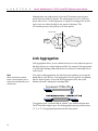
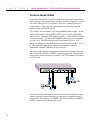
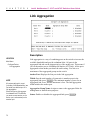
Link Aggregation
Link aggregation allows you to combine from two to four (adjacent) ports so
that they function as a single high-speed link. For example, link aggregation
is useful when making connections between switches or connecting servers
to the switch.
Note
When connecting to another
switch, connect anchor port to
anchor port and member port to
member port.
You can use link aggregation, also known as port trunking, to increase the
bandwidth to some devices. Link aggregation can also provide a redundant
link for fault tolerance. If one link in the aggregation fails, the switch
balances the traffic among the remaining links.
To aggregate ports, you must link an “anchor” port with an adjacent port.
The 470 switches support up to four link aggregation groups (anchor ports
1,3, 5, or 7). All aggregated ports must be the same speed.
12
C
H
A
P
T
E
R
2
Using the Intel® NetStructure™ 470T and 470F Switches
Guidelines
• The switch treats aggregated links as a single port. This includes
spanning tree and VLAN configurations.
• For the 470F: Anchor ports 1, 3, and 5 can each have up to four
aggregated ports; anchor port 7 can have two.
• All ports share the same settings as the anchor port. You can change
anchor port settings, but you cannot configure other ports in the link.
• When a port is configured as a member of an aggregated link, it adopts
the configuration of the anchor port. When a port is no longer a member
of an aggregated link, the configuration is reset to the default settings
(auto-negotiate speed/duplex, flow control enabled).
• If a port is part of an aggregated link, it cannot be configured as the
target port for a port mirror. However, a port in an aggregated link can
serve as the source port for a port mirror.
• When connecting to another switch, connect anchor port to anchor port,
and member port to member port.
Virtual LANs
A Virtual LAN (VLAN) is a logical network grouping you can use to isolate
network traffic so members of the VLAN receive traffic only from other
members. Creating a VLAN is the virtual equivalent to physically moving a
group of devices to a separate switch (creating a Layer 2 broadcast domain).
With VLANs you can reduce broadcast traffic for the entire switch, and
increase security, without changing the wiring of your network.
The 470 switches support three types of VLANs:
• Port-based
• Tag-based (IEEE 802.1Q)
• Protocol-based
13
Using the 470 Switch
• For the 470T: Anchor ports 1 and 3 can each have up to four aggregated
ports; anchor ports 5 and 7 can each have two.
C
H
A
P
T
E
R
2
Intel® NetStructure™ 470T and 470F Switches User Guide
Port-based VLANs
Port-based VLANs are the simplest and most common form of VLAN. In a
port-based VLAN, the system administrator assigns the ports to a specific
VLAN. For example, the system administrator can designate ports 1, 2, and
3 as part of the engineering VLAN and ports 5, 6, 7, and 8 as part of the
marketing VLAN. Port-based VLANs are easy to configure and all changes
are transparent to the users because they take place at the switch. The 470
switches support a maximum of four port-based VLANs. A port can belong
to only one port-based VLAN at a time.
If a user changes to another location, the system administrator reassigns the
port to the new VLAN. If a switch (or hub) is connected to a port that is part
of a VLAN, all devices connected to the switch are also part of the VLAN.
You cannot prevent an individual device on that switch from becoming part
of the VLAN.
Tag-based (IEEE 802.1Q) VLANs
The tag-based VLAN supported by the 470 switches is based on the IEEE
802.1Q specification. The specification provides a uniform way to create
VLANs within a network and allows you to create a VLAN that can span
across the network. Until the release of IEEE 802.1Q, it was not possible to
create a VLAN across devices from different vendors.
14
C
H
A
P
T
E
R
2
Using the Intel® NetStructure™ 470T and 470F Switches
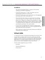
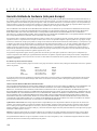
The 802.1Q VLAN works by using a tag added to the Ethernet frames. The
tag contains a VLAN Identifier (VID) that identifies the frame as belonging
to a specific VLAN. These tags allow switches that support the 802.1Q
specification to segregate traffic between devices and communicate a
device’s VLAN association across switches. The example below shows a
470F switch.
Local
Management
(EIA 232)
Status
Console: 9600-8-N-1
Flow Ctrl=None
1
Link\Activity
Link = Solid Green
Activity = Blinking Green
VLAN 1 computers
can't see VLAN 2
computers
2
3
4
5
6
7
8
Link\Act
1
2
3
4
5
6
7
8
TX
VLAN 1:
Engineering
Using the 470 Switch
Intel® NetStructure™ 470F Switch
RX
TX
RX
TX
RX
TX
RX
TX
RX
TX
RX
TX
RX
TX
RX
VLAN 2:
Manufacturing
Server and Printer
are members of both
VLANs
There are multiple advantages to implementing 802.1Q VLANs. First, it
helps to contain broadcast and multicast traffic across the switch thus
improving performance. Second, ports can belong to more than one VLAN.
Third, VLANs can span multiple switches that support the 802.1Q
specification. Finally, it can provide security and improve performance by
logically isolating users and grouping them.
A logical grouping can be mapped to a workgroup. For example, you can
create a VLAN that groups all the users from the engineering department.
Benefits of this logical grouping are: it improves performance by reducing
traffic that belongs to a different logical group (e.g. marketing), improves
security (engineering can’t see marketing), and eases moves because the
user doesn’t have to be physically located in the same group to participate in
the VLAN.
15
C
H
A
P
T
E
R
2
Intel® NetStructure™ 470T and 470F Switches User Guide
Protocol-based VLANs
In a protocol-based VLAN, traffic is bridged through specified ports based
on its protocol. Any packet using a different protocol is dropped as it enters
the switch. This type of VLAN allows you to use a common protocol to
communicate, yet prevents any packets that are not using the specified
protocol, from entering the switch.
For example, you can attach a LAN using NetBEUI traffic to port 1 on the
switch, and attach a LAN using IPX traffic to port 2 on the switch. Then,
attach a router connected to the Internet, to port 8. Create an IP VLAN that
incorportates ports 1, 2, and 8. The NetBEUI traffic on port 1is not passed
to ports 2 or 8. The IPX traffic on port 2 is not passed to ports 1 or 8.
However, computers using the IP protocol can talk freely to ports 1, 2, and
8. This allows the computers to connect to the Internet, yet not be
bombarded with traffic that they do not need to see.
The 470 switches support a maximum of four protocol-based VLANs, and
they can be either IP, IPX, NetBEUI, or all three combined. Each port can
be a member of only one protocol-based VLAN. The example below shows
a 470F switch.
Protocol-based VLANs can help optimize network traffic patterns because
protocol-specific broadcast messages are sent only to computers that use
that protocol. For example, if a NetBEUI VLAN is created, only NetBEUI
traffic is allowed to pass through the VLAN.
16
C
H
A
P
T
E
R
2
Using the Intel® NetStructure™ 470T and 470F Switches
Spanning Tree Protocol and VLANs
The 470 switches support the Spanning Tree Protocol across the entire
switch, not across each VLAN. If VLANs create a redundant link between
two switches and both of those switches have the Spanning Tree Protocol
enabled, one of the VLANs is disabled.
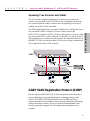
GARP VLAN Registration Protocol (GVRP)
Because tag-based (IEEE 802.1Q) VLANs can span across the network, it
poses a challenge for network administrators to manage changes to the
VLAN. The GARP VLAN Registration Protocol (GVRP) provides a
dynamic mechanism for switches to share topology information and manage
changes with other switches. This saves the network administrator from
having to manually propagate VLAN configuration information across
switches.
17
Using the 470 Switch
The following diagram shows an example. Both Switch 1 and Switch 2 have
two port-based VLANs configured. Crossover cables connect the
ENG_VLAN on Switch 1 to ENG_VLAN on and Switch 2. Crossover cables
also connect the MKT_VLAN on Switch 1 to the MKT_VLAN on Switch 2.
When spanning tree is enabled on both switches, the redundant link between
the MKT_VLANs is blocked and those VLANs can no longer communicate.
The example below shows 470F switches.
C
H
A
P
T
E
R
2
Intel® NetStructure™ 470T and 470F Switches User Guide
GARP (Generic Attribute Registration Protocol) is defined by the IEEE
802.1D (1998 Edition) specification and is the mechanism used by switches
and end nodes (servers, PCs, and so on) to propagate configuration across the
network domain. GVRP uses GARP as a foundation to propagate VLAN
configuration to other switches. Devices that support GVRP transmit their
updates to a known multicast address that all GVRP-capable devices monitor
for information updates.
Note
Dynamically created VLANs are
not saved in the switch’s
memory. If the device sending out
the GVRP updates is removed,
the dynamic VLAN is removed.
Sending GVRP messages between switches accomplishes the following tasks:
• Dynamically adds or removes a port from participating in a VLAN
• Sends updates about the switch’s own VLAN configuration to neighboring
GVRP-capable devices.
• Integrates dynamic and static VLAN configurations within the same
switch. For devices that don’t support GVRP, static VLAN configurations
are created by the user on the switch.
When the switch is running 802.1Q VLANs, Spanning Tree Protocol is
enabled for GVRP to work properly.
Internet Group Management Protocol (IGMP)
Normally, multicast traffic is broadcast by the switch to all ports. For
multicast traffic based on TCP/IP using the IGMP protocol, the switch can
optimize the broadcasting of multicast traffic by forwarding multicast traffic
only to ports that require it.
IGMP Snooping is a feature that allows the switch to forward multicast traffic
intelligently. The switch “snoops” the IGMP query and report messages and
forwards traffic only to the ports that request the multicast traffic. This
prevents the switch from broadcasting the traffic to all ports and possibly
affecting network performance.
IGMP Snooping requires a router that detects multicast groups on its subnets
and keeps track of group membership.
18
3
Using Intel® Device
View
Overview
Intel® Device View allows you to manage Intel NetStructure™ 470T and
470F switches and other supported Intel networking devices on your
network.
Intel Device View provides these features:
• The ability to configure new network devices
• A graphical device manager for Intel switches, hubs, and routers
• Autodiscovery, which finds supported Intel devices on the network
• The Device Tree, which shows all the supported devices detected
on your network
• Support for Remote Monitoring (RMON)
• Web or Windows* platform
• Plug-in to HP OpenView*, IBM Tivoli* NetView*, and Intel
LANDesk® Network Manager
• Other useful tools such as a TFTP server
19
C
H
A
P
T
E
R
3
Intel® NetStructure™ 470T and 470F Switches User Guide
Installing Intel Device View
Before you install Intel Device View, make sure your PC meets the system
requirements in the Intel® Device View User Guide, which is included on
the Intel Device View CD-ROM.
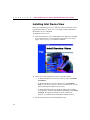
To install Intel Device View
1 Insert the Intel Device View CD-ROM into your computer’s CD-ROM
drive. The Intel Device View installation screen appears. If it doesn’t
appear, run autoplay.exe from the CD-ROM.
2 Choose the version of Intel Device View you want to install.
• To install Intel Device View for use on this PC only, click Install
for Windows.
• To install Intel Device View on a Web server, click Install for
Web. You can access the Device View server from any PC on your
network with Internet Explorer* 4.0x or later.
• To install Intel network device support for HP OpenView, IBM
Tivoli NetView, or Intel LANDesk Network Manager, click Install
as Plug-in. This option is available if you have OpenView,
NetView, or LANDesk Network Manager installed on the PC.
3 Follow the instructions in on the installation screens.
20
C
H
A
P
T
E
R
3
Intel Device View
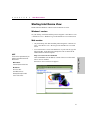
Starting Intel Device View
Install either the Windows or Web version of Intel Device View.
Windows* version
On your desktop, click Start and then point to Programs > Intel Device View
> Intel Device View - Windows to go to the Intel Device View main screen.
Web version
NOTE
Web browser
On your desktop, click Start and then point to Programs > Intel Device
View > Intel Device View - Web to go to the Intel Device View main
screen.
•
To view Intel Device View from another PC on your network, type the
following URL. In the following example, the URL is entered in the
Address field for Internet Explorer.
http://servername/devview/main.htm
where servername is the IP address or name of the server where Intel
Device View is installed.
Intel® Device View
These are the requirements if you
want to use the Web version of
Device View :
•
Intel Device View’s main screen appears.
Internet Explorer 4.0 or later
Web Server
IIS* 2.0 or later
Peer Web Services*
Netscape Enterprise* Web
Server 3.01 or later
21
C
H
A
P
T
E
R
3
Intel® NetStructure™ 470T and 470F Switches User Guide
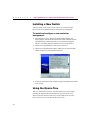
Installing a New Switch
After you install a new switch on your network, you can use the Intel
Device View Device Install Wizard to configure it for management.
To install and configure a new switch for
management
1 Start Intel Device View. The Device Install Wizard appears. If it
doesn’t appear, click Install from the Device menu or double-click the
appropriate MAC address in the Device Tree under Unconfigured
Devices. (The MAC address is located on the rear of the switch.)
2 On the Device Install Wizard - Start screen, click Next.
3 On the Device Install Wizard - MAC Address screen, click the MAC
address of the new switch, and then click Next.
4 Follow the instructions in the wizard to assign an IP address and a name
to the switch.
Using the Device Tree
After you start Intel Device View, the Device Discovery service begins
searching for supported Intel network devices on your network. As it
discovers devices, the Device Discovery service adds an icon for each
device to the Device Tree on the left side of the screen.
22
C
H
A
P
T
E
R
3
Intel Device View
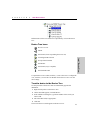
Different states of the 470 switches are represented by icons in the Device
Tree.
Device Tree icons
Device Tree root
Subnet
Intel Switch (if non-responding the icon is red)
Unconfigured Intel Switch
Intel® Device View
Group of Intel Switches
Intel Router
Intel Switch (Layer 3 capable)
Intel Stackable Hub
To expand the root or a subnet, click the (+) next to the icon. To collapse the
view, click the (-) next to the icon. Double-click a device icon to view the
device image.
To add a device to the Device Tree
Use this procedure if the device does not automatically appear after
installation.
1 Right-click anywhere on the Device Tree.
2 On the menu that appears, click Add Device.
3 In the Add Device dialog box, type the IP address of the switch you
want to add.
4 Fill in the other fields, as appropriate.
5 Click OK.
The icon for the new switch appears in the Device Tree.
23
C
H
A
P
T
E
R
3
Intel® NetStructure™ 470T and 470F Switches User Guide
To refresh the Device Tree
Refreshing the Device Tree updates it to show any newly discovered
devices and changes in device status.
1 Right-click anywhere on the Device Tree.
2 On the menu that appears, click Refresh.
To delete a device from the Device Tree
1 Right-click the device you want to remove from the Device Tree.
2 On the menu that appears, click Delete.
Deleting a device from the Device Tree does not remove the device from the
network.
To find a device in the Device Tree
1 On the Device Tree, right-click anywhere.
2 On the menu that appears, click Find.
3 In the Find Device dialog box, type the IP address of the device you
want to find in the tree.
4 Click OK.
The device icon is highlighted in the Device Tree.
Losing contact with a switch
If Intel Device View loses contact with a switch, the color of the switch icon
changes to red, to indicated that the switch is not responding.
If the non-responding switch icon appears, you cannot manage the device in
Intel Device View. If you’re unable to ping the device or start a Telnet
session, try accessing the switch’s Local Management.
24
C
H
A
P
T
E
R
3
Intel Device View
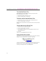
Managing a Switch
To manage a 470T or 470F switch, double-click the switch icon in the
Device Tree. In the example following, the switch has been assigned an IP
address of 124.123.122.3.
The 470 switch Web Device Manager appears in the Intel Device View
window. For information about using the Web Device Manager, see Ch. 4.
Intel® Device View
For information about using Intel Device View, see the Help or the User
Guide on the Intel Device View installation CD-ROM.
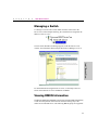
Viewing RMON Information
The Remote Monitoring (RMON) specification extends SNMP functionality
to look at traffic patterns on the network instead of looking only at the
traffic for an individual device. The following RMON groups are supported:
25
C
H
A
P
T
E
R
3
Intel® NetStructure™ 470T and 470F Switches User Guide
• Group 1 (Statistics): Monitors utilization and error statistics for each
network segment (100Mbps or 1000Mbps).
• Group 2 (History): Records periodic statistical samples from variables
available in the statistics group.
• Group 3 (Alarms): Allows you to set a sampling interval and alarm
thresholds for statistics. When a threshold is passed, the switch creates an
event. For example, you might set an alarm if utilization exceeds 30%.
• Group 9 (Events): Provides notification and tells the switch what to do
when an event occurs on the network. Events can send a trap to a
receiving station or place an entry in the log table, or both. For example,
when the switch experiences an RMON Event, it sends out an alarm.
The switch also keeps a log that shows a list of the RMON Events and
RMON Alarms that have occurred on the switch.
To view RMON statistics
1 In the Device Tree, right-click the switch’s icon, and then point to RMON.
2 Click the RMON option you want to view.
You can also access RMON features using LANDesk Network Manager, or an
SNMP application that supports RMON such as HP OpenView or IBM Tivoli
NetView. For more information about using RMON to monitor the switch, see
the Intel Device View Help.
26
4
Using the Web
Device Manager
Overview
NOTE
You can use Internet Explorer*
or Navigator* to access the Web
Device Manager.
With the Web Device Manager, which is built into the Intel® NetStructure™
470T and 470F Switches, you can use a Web browser to manage and
monitor the switch. For example, you can use the Web Device Manager to
configure the switch or individual ports, or to monitor traffic statistics and
utilization.
For more information about using this interface, see the Web Device
Manager Help.
27
C
H
A
P
T
E
R
4
Intel® NetStructure™ 470T and 470F Switches User Guide
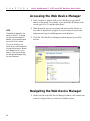
Accessing the Web Device Manager
1 In the Location or Address field of your Web browser type the IP
address of the switch. For example, to use the default IP address of the
switch, type 192.0.2.1 and then press Enter.
NOTE
The default IP address for the
switch is 192.0.2.1. To access
the switch with the default IP
address, your workstation must
be on the 192.0.2.0 subnet.
2 When prompted, type your user name and password. By default, no
user name or password is assigned. If you previously set a user name
and password using Local Management, enter them here.
3 Click OK. The Web Device Manager window appears in your Web
browser.
Or, you can connect to the
switch using Local Management
(through the serial port) and set
an IP address that is on your
network. Then you can access
the Web Device Manager using
the new IP address.
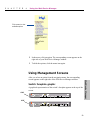
Navigating the Web Device Manager
1 On the left side of the Web Device Manager window, click a menu item
(such as Configure Device) to show the available options.
28
C
H
A
P
T
E
R
4
Using the Web Device Manager
Click a menu to view
available options.
2 In the menu, click an option. The corresponding screen appears on the
right side of your Web Device Manager window.
3 To hide the options, click the menu item again.
Using Management Screens
Switch faceplate graphic
A graphical representation of the switch’s faceplate appears at the top of the
screen.
470F
470T
29
Web Device Manager
After you select an option from the navigation menu, the corresponding
screen appears on the right side of the Web Device Manager window.
C
H
A
P
T
E
R
4
Intel® NetStructure™ 470T and 470F Switches User Guide
If the option you selected allows you to configure or monitor a specific port,
you can change to another port by clicking it on the faceplate graphic.
Port color on the faceplate graphic indicates the status of the port.
Port Color
Meaning
Blue
Port has a link at 1000Mbps.
Green
Port has a link at 100Mbps.
Magenta outline
Ports are in a link aggregation.
Orange
Port is disabled.
Gray
No link.
Buttons
Each configuration screen includes four buttons on the bottom of the screen.
30
Button
Function
Submit
Applies the configuration settings on the current screen.
Note: If you do not save the settings to the switch’s flash
memory your changes are lost when the switch is rebooted.
Reset
Clears any changes you made on the current screen and
restores the currently applied settings.
Default
Applies factory defaults for this screen’s settings. When
you log out, you can permanently save the new settings to
the switch. Otherwise, they are lost upon the next reboot.
Help
Displays Help for the current screen.
C
H
A
P
T
E
R
4
Using the Web Device Manager
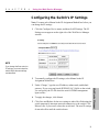
Configuring the Switch’s IP Settings
Note: You must select Manual in the IP Assignment Method box before you
can change the IP settings.
1 Click the Configure Device menu, and then click IP Settings. The IP
Settings screen appears on the right side of the Web Device Manager
window.
NOTE
If you change the flow control or
IP settings, you must reboot the
switch before the new settings
can take effect.
2 To manually configure the IP settings, select Manual in the IP
Assignment Method box.
4 To apply the changes, click Submit.
5 Click Save and Reboot for the new settings to take effect. Rebooting the
switch temporarily interrupts network connectivity to the switch. Click
Reboot Later if you want to reboot the switch later. The new IP settings
do not take effect until the switch reboots.
31
Web Device Manager
3 Under “Change,” type the new IP address, subnet mask, and default
gateway. If you set up tag-based (IEEE 802.1Q) VLANs on the switch,
you can specify the VLAN where the switch’s SNMP management
agent resides.
C
H
A
P
T
E
R
4
Intel® NetStructure™ 470T and 470F Switches User Guide
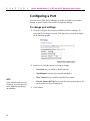
Configuring a Port
You can use the Web Device Manager to enable or disable a port, and to
change its speed, duplex, flow control, and priority settings.
To change port settings
1 Click the Configure Device menu, and then click Port Settings. To
access the Port Settings for a port, click the port you want to configure
on the faceplate graphic.
2 In the boxes, click the options you want to change:
•
Port State lets you enable or disable the port.
•
Speed/Duplex lets you set port speed and duplex.
•
Flow Control lets you enable or disable flow control.
•
Priority Queue (802.1p) lets you set the switch priority queue for
packets sent or received on this port.
NOTE
If you change the flow control or
IP settings, you must reboot the
switch before the new settings
can take effect.
32
3 Click Submit.
C
H
A
P
T
E
R
4
Using the Web Device Manager
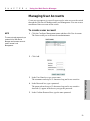
Managing User Accounts
Create user accounts to give specific users read or write access to the switch
through the Web Device Manager and Local Management. You can create a
maximum of three accounts on the switch.
To create a user account
NOTE
1 Click the Configure Management menu and then click User Accounts.
The first account you create must be an administrator.
The accounts and passwords you
create with the Web Device
Manager are the same accounts
used to access Local
Management.
2 Click Add.
Web Device Manager
3 In the User Name box, type a user name.
The username can be up to 15 characters long and is case sensitive.
4 In the Password box, type a password.
The password can be up to 15 characters long and is case sensitive.
Asterisks (*) appear in the box as you type the password.
5 In the Confirm Password box, type the same password.
33
C
H
A
P
T
E
R
4
Intel® NetStructure™ 470T and 470F Switches User Guide
6 In the Access Level box, click an access level. An administrator can
view all settings and make configuration changes. A user can only view
settings.
7 Click Submit.
To delete a user account
1 Click the Configure Management menu, and then click User Accounts.
2 In the User Accounts box, click the account you want to delete.
3 Click Delete.
If you delete the account you used to log in for this session, you can
continue to use that account until you log out. If you delete the only user
account on the switch, log in again using the default of no user name and no
password.
34
C
H
A
P
T
E
R
4
Using the Web Device Manager
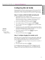
Configuring VLANs
VLANs provide a way to create a logical network grouping without regard
to physical location of the network nodes.
For more information about VLANs, see “Virtual LANs” in Chapter 2.
There are two main steps to set up a VLAN with the Web Device Manager:
• Set the switch’s VLAN operation mode.
• Configure the type of VLAN you selected.
NOTE
You can only have one operation
mode active on the switch at a
time.
To set the switch’s VLAN operation mode
1 Click the Configure VLAN menu, and then click VLAN Operation
Mode.
2 In the Current VLAN mode box, click the type of VLAN to set up.
3 Click Submit.
After the switch reboots, you can configure the type of VLAN that you
selected.
35
Web Device Manager
4 The switch automatically reboots. The 470 switches are rebooted
whenever you change their VLAN operation mode.
C
H
A
P
T
E
R
4
Intel® NetStructure™ 470T and 470F Switches User Guide
Port-based VLAN
You configure a port-based VLAN by creating the VLAN and then adding
participating ports. The switch can support up to four port-based VLANs.
However a port can be a member of only one VLAN; port-based VLANs
cannot overlap.
To configure a port-based VLAN
1 Click the Configure VLAN menu, and then click Port-based VLAN.
2 Click Add to create a new VLAN, or select a VLAN and click Edit to
change its configuration.
3 If you are creating a new VLAN, type a name in the VLAN Name box.
4 In the Available Ports box, click a port to add to the VLAN, and then
click Add.
5 When you finish adding ports, click Submit.
36
C
H
A
P
T
E
R
4
Using the Web Device Manager
Tag-based VLAN
You configure a tag-based VLAN by configuring port membership and
ingress/egress rules. Note: If some of your devices don’t support 802.1Q
tags, additional configuration may be necessary.
To configure a tag-based (IEEE 802.1Q) VLAN
1 Create a VLAN and assign member ports.
• Click the Configure VLAN menu, and then click Tag-based (IEEE
802.1Q) VLAN.
• From the main Tag-based VLAN page, click Add to create a new
VLAN. To modify an existing VLAN, click the VLAN name, and
click Modify.
NOTE
• If you are creating a new VLAN, type a name and VID (from 2 to
4094) to identify it.
When creating a VLAN that
includes ports on more than one
switch, set the same VID on each
switch.
• The switch supports a maximum of 12 IGMP Snooping sessions to
manage broadcast traffic. If you want the VLAN to be part of an
IGMP Snooping session, select the Enable IGMP Snooping check
box.
• When you finish adding ports, click Next.
37
Web Device Manager
• To configure membership of a port to a VLAN, click the port in the
Available ports box and click Add. To remove a port, click the port in
the Member ports box and click Remove.
C
H
A
P
T
E
R
4
Intel® NetStructure™ 470T and 470F Switches User Guide
2 Configure ports for egress (outbound) tagging.
• Ensure that the VLAN Name field displays the name of the port you
are configuring.
• For each of the VLANs ports select Tag or Untag. This determines
whether or not the system will remove (untag) tags before sending
traffic out of each port.
3 Configure ports for handling untagged traffic.
• On the main Tag-based VLAN page, click Port Settings.
• On the Port Settings screen you can set port-specific behaviors for
processing VLAN traffic. To configure a specific port, click it on the
faceplate graphic. To configure the same setting across all ports, click
Configure All Ports.
38
C
H
A
P
T
E
R
4
Using the Web Device Manager
Options include:
• Default Port VID: Sets the PVID to be assigned to untagged traffic
on a given port. For example, if port 7’s default PVID is 100, all
untagged packets on port 7 belong to VLAN 100. The default setting
for all ports is VID 1.
• GVRP: Allows automatic VLAN configuration between the switch
and nodes.
• Ingress Filtering: Allows frames belonging to a specific VLAN to
be forwarded if the port belongs to the same VLAN. Disabling this
setting will cause all frames to be forwarded, regardless of the port's
VLAN membership.
4 When you finish changing the settings, click Submit.
Web Device Manager
39
C
H
A
P
T
E
R
4
Intel® NetStructure™ 470T and 470F Switches User Guide
Protocol-based VLAN
You configure a protocol-based VLAN by creating the VLAN and then
adding participating ports. The switch supports up to three protocol-based
VLANs: IP, IPX, and NetBEUI. However, each port can be a member of
only one VLAN; protocol-based VLANs cannot overlap.
To configure a protocol-based VLAN
1 Click the Configure VLAN menu, and then click Protocol-based
VLAN.
2 Click Add to create a new VLAN, or select an existing VLAN and click
Edit to change its configuration.
3 If you are creating a new VLAN, type a name in the VLAN Name box
and select a protocol from the Protocol list.
4 In the Available Ports box, click a port to add to the VLAN, and then
click Add.
5 When you finish adding ports, click Done.
40
C
H
A
P
T
E
R
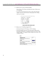
NOTE
When configuring link
aggregation between two 470
switches, you must connect
anchor port to anchor port, and
member port to member port.
NOTE
Connectivity is momentarily
interrupted when you submit
changes.
4
Using the Web Device Manager
Link Aggregation
On the Web Device Manager’s switch faceplate graphic, a link aggregation
is shown with its ports outlined in magenta (pink).
To create a link aggregation
1 Click the Configure Device menu, and then click Link Aggregation.
2 Choose the anchor port. Anchor ports are listed by port number in the
left column.
3 In the Port Width box, click the number of ports (including the anchor
port) to include in the link aggregation.
4 In the Aggregation Group Name box, type a name for the aggregation.
5 Click Enable to activate the group.
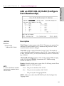
Static MAC Addresses
The switch has a MAC address table that stores all the MAC addresses that
it learns from the network. The switch refers to this table forwarding traffic
to specific ports, so it does not broadcast traffic to every port.
There are two ways to add addresses to the MAC address table:
•
The switch can learn addresses from the network and add them
dynamically. Dynamic entries remain in the table only while the
associated node is active, and are deleted if the node is inactive for
longer than a certain period of time (age-out time).
41
Web Device Manager
6 Click Submit.
C
H
A
P
T
E
R
4
Intel® NetStructure™ 470T and 470F Switches User Guide
•
You can manually add MAC addresses to the table. These are called
static addresses, because they remain in the table until you remove
them, even if the associated node is inactive or removed from the
network. Performance and security issues are two reasons for adding
static addresses.
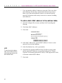
To add a static MAC address to the address table
1 Click the Configure Device menu, and then click Forwarding and
Filtering.
2 Click Static MAC Addresses.
3 Click Add.
4 In the MAC Address box, type the MAC address of a device on the
network. Do not include hyphens.
5 In the Port Number box, click a port number.
NOTE
To view the switch’s address
table, click the Monitor menu,
click Advanced, and then click
MAC Address Table.
6 If port-based or tag-based (IEEE 802.1Q) VLANs are set up on the
switch, static MAC addresses are associated with specific VLANs.
Type the VLAN name (port-based VLANs) or VID (tag-based VLANs)
to associate with the MAC address.
7 Click Add.
42
C
H
A
P
T
E
R
4
Using the Web Device Manager
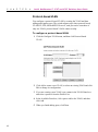
Setting Up Priority Tagging
With priority tagging, you can specify a priority value for traffic based on
MAC source or destination addresses. For example, you could tag all
packets from computer A with a priority of 7 (high).
When you define priority tagging, you can specify a priority value from 0
(low) to 7 (high). Traffic with a priority value of 0–3 is routed through the
switch’s low priority queue. Traffic with a priority value of 4–7 is routed
through the switch’s high priority queue.
You can define up to 12 MAC addresses for priority tagging.
To set up priority tagging
1 Click the Configure Device menu, and then click Priority Tagging.
2 Click Add.
3 Select source or destination as the criteria for the tagged traffic.
Web Device Manager
4 Type the source or destination MAC address.
5 Select a priority value.
Traffic tagged with priority values 0–3 is routed through the switch’s
low priority queue. Traffic tagged with priority values 4–7 is routed
through the switch’s high priority queue.
6 In the State box, click Enabled to enable priority tagging for the traffic
pattern.
7 Click Done when you are finished.
43
C
H
A
P
T
E
R
NOTE
4
Intel® NetStructure™ 470T and 470F Switches User Guide
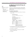
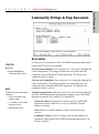
Configuring Community Strings and
Trap Receivers
• Power to the switch was
cycled or reset.
A trap receiver is a computer on the network that is running an SNMP
management application and receives messages sent by the switch. For
example, the switch can send a trap to the trap receiver when it detects a
change in port speed.
• Link, speed, or other status
changes on a port.
To specify a trap receiver
These are the traps supported by
the switch:
• Authentication failure.
1 Click the Configure Management menu, and then click Community
Strings and Traps.
2 In the IP Address box, type the IP address of the computer you want to
use as a trap receiver. You can specify up to four trap receivers.
3 In the Status box, click Enabled.
4 In the Community String box, type the trap receiver’s SNMP
application community string.
5 Click Submit.
44
C
H
A
P
T
E
R
4
Using the Web Device Manager
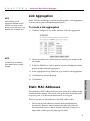
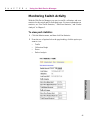
Monitoring Switch Activity
With the Web Device Manager you can view traffic, utilization, and error
statistics for the switch and for individual ports. For more information on
statistics, see “Port Traffic Statistics,” “Port Error Statistics,” and “Packet
Analysis” in Chapter 5.
To view port statistics
1 Click the Monitor menu, and then click Port Statistics.
2 From the row of options below the page heading, click the option you
want to view:
•
•
•
•
Traffic
Utilization Graph
Errors
Packet Analysis
Web Device Manager
45
C
H
A
P
T
E
R
4
Intel® NetStructure™ 470T and 470F Switches User Guide
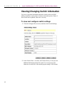
Viewing/Changing Switch Information
You can view general information about the switch, such as its MAC
address, firmware version, name, location, and contact person. Some of
these fields can be updated, others are view-only.
To view and configure switch settings
1 Click the Configure Device menu, and then click Switch Settings.
2 In the Switch Name , Location, and Contact boxes you can provide
additional information about the switch. You can type up to 40
characters in each field. After modifying the settings, click Submit.
46
C
H
A
P
T
E
R
4
Using the Web Device Manager
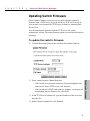
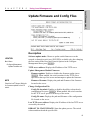
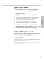
Updating Switch Firmware
On the Update Firmware screen you can set up the switch to update its
firmware from a TFTP server. If you do not have a TFTP server set up on
your network, you can install the TFTP server software by installing Intel
Device View.
After downoading the firmware from the TFTP server, the switch
automatically restarts. The actual firmware update occurs while the switch is
rebooting.
To update the switch’s firmware
1 Click the Reset and Update menu, and then click Update Firmware.
• If the switch uses a network connection for downloading the new
firmware file from a TFTP server, click Network.
• If the switch uses a SLIP connection (for example, a serial port) for
downloading the new firmware file, click SLIP.
3 In the TFTP Server Address box, type the IP address of the server that
hosts the file.
4 In the Firmware Update box, click Enabled.
47
Web Device Manager
2 Select a mode from the Update Mode box.
C
H
A
P
T
E
R
4
Intel® NetStructure™ 470T and 470F Switches User Guide
5 In the File Name box, type the name of the firmware file.
6 Click Submit.
The switch automatically reboots.
The next time the switch reboots it downloads and installs the new firmware
during the boot process. If you want to view this process, you must use a
terminal program and connect to the switch through the serial port.
Saving Configuration Changes and
Logging Out
Each time you make configuration changes using the Web Device Manager,
the switch immediately uses the new settings. However, when you log out
of the Web Device Manager, you’ll be prompted to save the current
configuration settings.
If you do not save the new configuration settings to the switch’s flash
memory, the settings are lost upon the next switch reboot.
To save changes and log out
1 Click Log Out from the menu.
2 Click Save Now to save the current configuration settings. The Web
browser window closes and you are successfully logged off of the Web
Device Manager.
If you click Do Not Save, all current configuration settings are lost the
next time the switch is rebooted.
48
C
H
A
P
T
E
R
5
Using Local Management
Local Management
5
Using Local
Management
Overview
Another way to configure the switch is through the Local Management
interface. Local Management provides the same functionality as the Web
Device Manager using a text-based interface.
Accessing Management
You can access Local Management in two different ways: by connecting
directly to the switch’s serial port, or through a Telnet session (using an
assigned IP address or the default of 192.0.2.1).
To use the serial port
1 Use the enclosed null modem cable to connect the serial port of your PC
to the serial port of the switch.
2 Start a terminal emulation program (such as HyperTerminal* or
Symantec Procomm Plus* in Windows* 98). Use these communication
parameters:
• 9600 baud
• 1 stop bit
• 8 data bits
• No flow control
• No parity
NOTE
3 Press E to connect to the Local Management.
You use the same user name and
password to log in to Web Device
Manager and Local Management.
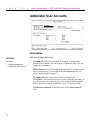
4 Log on to Local Management. By default, no password or username is
assigned. To assign them, see the section titled “Administer User
Accounts” in this chapter.
49
C
H
A
P
T
E
R
5
Intel® NetStructure™ 470T and 470F Switches User Guide
To useTelnet
1 Open a Telnet application. In Windows 98 or Windows NT*, select
Run from the Start Menu, and then type telnet and press E.
2 On the Terminal menu, select Preferences. Make sure the emulation
type is VT-100/ANSI and that VT100 arrows are enabled.
3 On the Connect menu, select Remote System. Enter the IP address of
the switch and click Connect.
4 Log on to Local Management. By default, no password or user name is
assigned. To assign them, see the section titled “Administer User
Accounts” in this chapter.
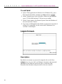
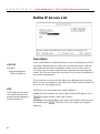
Logon Screen
Description
By default, no username or password is assigned to the switch. Press
E twice to log on to the Local Manager. Usernames and passwords
can consist of any characters and can be up to 15 characters long.
Remember that usernames and passwords are also case sensitive.
50
C
H
A
P
T
E
R
5
Using Local Management
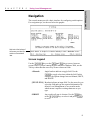
The console menus provide a basic interface for configuring switch options.
For navigation tips, see the text below the graphic.
Help text at the bottom of
the screen provides information on the selected
item.
Screen Legend
Use the W Z A S keys or the T and b keys to move between
screen fields. If you are running HyperTerminal in Windows 2000, use the
Tab key rather than the arrow keys to move between fields.
<Manual>
Angle brackets indicate a toggle field. Use the
z to toggle selections within the field. In this
example, the options change between Manual, DHCP,
and BOOTP.
[255.255.255.0] Brackets indicate an input field. Use the arrow keys to
select the field and type the required information. By
default, Local Management is in overstrike mode,
which means it replaces existing characters as you
type.
SUBMIT
Any word in all caps is a button. Use the T key
or the W Z A S keys to select it and press E
to use it.
51
Local Management
Navigation
C
H
A
P
T
E
R
5
Intel® NetStructure™ 470T and 470F Switches User Guide
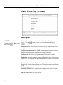
Main Menu (Top Screen)
Description
LOCATION
To return to the Main Menu at any
time, press c T.
The Main Menu is the starting point for all other Local Management
screens. Use the W Z arrow keys to select an option, and then press
E to display the screen.
Configure device: Accesses menus to assign an IP address to the switch,
change port settings, or configure advanced switch settings.
Configure management: Sets SNMP traps and trap monitoring stations,
administers user accounts, or updates the switch’s firmware.
Configure VLAN: Sets up and administers VLANs on the switch.
Monitoring: Accesses menus to monitor traffic and activity at the port or
switch level. These menus also provide information on network errors and
collisions.
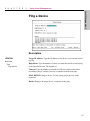
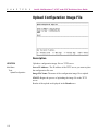
Tools: Displays the switch Trap/Event log, pings devices to check
connectivity, or saves the current switch configuration to an image file on a
server.
SAVE SETTINGS: Saves configuration changes to the switch’s flash
memory. Any changes not saved to memory are lost on the next reboot.
LOGOUT: Returns to the logon screen.
52
C
H
A
P
T
E
R
5
Using Local Management
Local Management
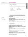
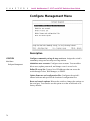
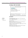
Configure Device
Description
LOCATION
Main Menu
Configure Device
IP settings: Configures the switch’s IP address, subnet mask, and default
gateway, or enables BOOTP.
Port settings: Enables and disables ports, configures port speed, duplex,
flow control, and priority.
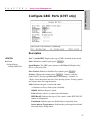
GBIC port settings (470T only): Enables and disables ports, configures
port speed, duplex, flow control, and priority.
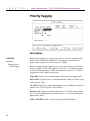
Priority tagging: Sets priority values for traffic based on source or
destination MAC addresses.
Switch settings: Sets switch identification, location, and contact
information, and configures some advanced switch settings.
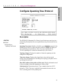
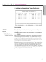
Spanning Tree Protocol: Configures spanning tree for the entire switch or
individual ports.
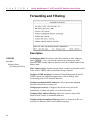
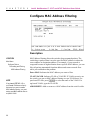
Forwarding and filtering: Adds or removes entries, locks the switch’s
address table, enables IGMP snooping, and sets filters for specific MAC
addresses.
Port mirroring: Sends a copy of data from one port to another for
monitoring and troubleshooting purposes.
Link aggregation: Combines ports on the switch to increase bandwidth.
Broadcast storm control: Configures ports to drop excessive broadcast
traffic before it floods the network.
53
C
H
A
P
T
E
R
5
Intel® NetStructure™ 470T and 470F Switches User Guide
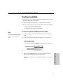
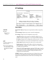
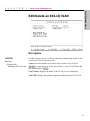
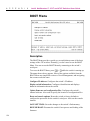
IP Settings
Description
LOCATION
Main Menu
Configure Device
IP Settings
Switch MAC address: Displays the unique hardware address assigned by
Intel.
Current Settings: Displays the switch’s current IP configuration.
New settings: Assigns a new IP configuration to the switch.
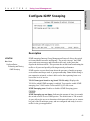
Assign IP: Indicates if the switch uses a BOOTP or DHCP server to
obtain an IP address dynamically, or if you assign an address manually.
NOTE
The default IP address for the
switch is 192.0.2.1
Default VLAN for SNMP agent
Port-based: DEFAULT_VLAN
tag-based (802.1Q-based):
VID=1
IP address: Displays the IP configuration used by the switch. Use the
IP address shown here to access the switch through Telnet or a ping test.
Subnet mask: Matches the mask for other devices on the network.
Default gateway: Displays the IP address of the device that routes to
different networks—typically, a router or routing server. Set this option
to manage the switch remotely.
VLAN or VLAN ID (port-based or tag-based VLANs only): Specifies
a VLAN where the switch’s SNMP management agent will reside. This
option appears only when port-based and tag-based (IEEE 802.1Q)
VLANs are active on the switch.
SUBMIT: Submits the changes and returns to the Configure Device screen.
You must save the changes to the switch’s flash memory (from the Save
Settings menu) and then reboot the switch for the new IP settings to take
effect.
54
C
H
A
P
T
E
R
5
Using Local Management
Local Management
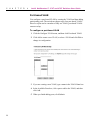
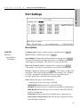
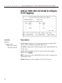
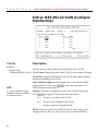
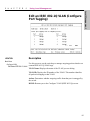
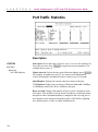
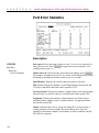
Port Settings
Description
LOCATION
Configure ports: Selects a range of ports to configure (press z).
Main Menu
State: Disables or enables ports (press z).
Configure Device
Port Settings
Speed/Duplex: Changes the speed and duplex of the port (press z).
You can set the port to auto-negotiate speed, or to 100Mbps or 1000Mbps
at half-duplex or full-duplex. This field is view-only for the 470F.
Flow Ctrl (Control): Enables or disables flow control (press z).
This option is view-only if auto-negotiate is selected for Speed/Duplex.
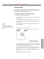
Priority: Changes the settings (press z). The <Frame> setting reads
the packet’s 802.1p priority tag and handles it accordingly. The <Normal>
or <High > settings force the packet into one of two priority queues.
Forcing a packet into a queue does not retag the packet.
Link: Indicates the port’s current link status:
--: Indicates no device link or port is disabled.
100M/1000M: Indicates the port’s speed (470T only).
Full/Half: Indicates a device is connected at full-duplex or half-duplex.
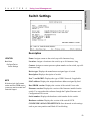
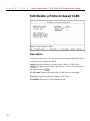
IEEE/BackP: Indicates the type of flow control, either IEEE PAUSE
frames or backpressure.
Partitioned: Indicates the port was disabled due to a partition error.
Source mirror/Target mirror: Indicates the port being mirrored and
where the data is being sent.
55
C
H
A
P
T
E
R
5
Intel® NetStructure™ 470T and 470F Switches User Guide
Flow Control
During times of heavy network activity, the switch’s port buffers can
receive too much traffic and fill up faster than the switch can send the
information. In cases like this, the switch tells the transmitting device to
wait so the information in the buffer can be sent. This intervention is called
flow control.
The method of flow control depends on whether the ports are set to fullduplex or half-duplex. If a port is operating at half-duplex, the switch sends
a collision which causes the transmitting device to wait. If the port operates
at full-duplex, the switch sends out an 802.3x PAUSE frame. You can
enable or disable flow control for each port on the NetStructure™ 470
switches.
Priority
IEEE 802.1p is part of a new standard for tagging, or adding additional
information (4 bytes) to packets to indicate a priority level. When these
packets are sent out on the network, the higher priority packets are
transferred first. Priority packet tagging (also known as Traffic Class
Expediting) is usually set at the adapter and works with other elements of
the network (switches, routers) to deliver priority packets first. 802.1p
tagging consists of eight levels from 0 (low) to 7 (high).
The NetStructure™ 470 switches have the ability to read IEEE 802.1p
priority tags and forward traffic on a per port basis. Each switch has two
priority queues and routes traffic to a queue depending on the packet’s tag.
For example, when a packet comes into the switch with a high priority tag,
the switch routes the packet to its high-priority queue.
Even though there are eight priority levels, the switch can only route a
packet into one of the two queues. The switch maps levels 0-3 to the low
queue and levels 4-7 to the high queue. If a packet is untagged, the switch
determines the best way to send the packet.
56
C
H
A
P
T
E
R
5
Using Local Management
Local Management
Configure GBIC Ports (470T only)
Description
LOCATION
Port 7- and 8-GBIC: Displays the type of GBIC installed on the switch.
Main Menu
State: Disables or enables ports (press z).
Configure Device
Configure GBIC Ports
Speed/Duplex: The GBIC ports operate at 1000Mbps/full-duplex only;
this is a view-only field.
Flow Control: Enables or disables flow control (press z).
Priority: Changes the settings (press z). <Frame> reads the
packet’s 802.1 priority tag and handles it accordingly. <Normal> or
<High> forces the packet into one of two priority queues. Forcing a packet
into a queue does not retag the packet.
Link: Indicates the port’s current link status:
--: Indicates no device link or port is disabled.
1000M: Indicates the port’s speed.
Full: Indicates a device is connected at full-duplex.
IEEE/BackP: Indicates the type of flow control, either IEEE PAUSE
frames or backpressure.
Partitioned: Indicates port was disabled due to a partition error.
Source mirror/Target mirror: Indicates the port being mirrored and
where the data is being sent to.
57
C
H
A
P
T
E
R
5
Intel® NetStructure™ 470T and 470F Switches User Guide
Priority Tagging
Description
LOCATION
Main Menu
Configure Device
Priority Tagging
With priority tagging, you can specify a priority value for traffic based on
MAC source or destination addresses. For example, you could tag all
packets from computer A with a priority of 7 (high).
When you define priority tagging, you can specify a priority value from 0
(low) to 7 (high). Traffic with a priority value of 0 - 3 is routed through the
switch’s low priority queue. Traffic with a priority value of 4 - 7 is routed
through the switch’s high priority queue.
Tag traffic: Select source or destination as the criteria for tagged traffic.
Enter MAC: Type the source or destination MAC address of traffic to tag
with a priority value.
VLAN ID: If the device whose MAC address you are adding to the list is a
member of a VLAN, type the VLAN ID here.
Priority level: Toggle to the desired priority level. Traffic with a priority
of 0–3 is routed through the low priority queue; 4–7 is routed through the
high priority queue.
ADD or DELETE: Adds or deletes the specified MAC address.
58
C
H
A
P
T
E
R
5
Using Local Management
Local Management
Switch Settings
Description
LOCATION
Name: Assigns a name to the switch, up to 40 characters long.
Main Menu
Location: Assigns a location to the switch, up to 40 characters long.
Configure Device
Switch Settings
Contact: Assigns a contact person or phone number to the switch, up to 40
characters long.
Device type: Displays the manufacturer-assigned type of switch.
Description: Displays description of switch.
Port 7- and 8-GBIC: Displays the type of GBIC detected, if applicable.
NOTE
Write down both the firmware
version and Boot PROM version
in case you need to contact Intel®
Customer Support.
MAC address: Displays the unique hardware address assigned by Intel.
Boot PROM version: Displays the version of the switch’s boot code.
Firmware version: Displays the version of the firmware installed on the
switch. You can update this software through the Update Firmware and
Configuration Files screen.
Serial number: Displays the hardware serial number for the switch.
Hardware revision: Displays the version of the switch’s PCB.
CONFIGURE ADVANCED SETTINGS: Sets advanced switch settings
such as port auto-partition and Head of Line blocking.
59
C
H
A
P
T
E
R
5
Intel® NetStructure™ 470T and 470F Switches User Guide
Configure Advanced Switch Settings
Description
LOCATION
Main Menu
Configure Device
Switch Settings
Configure Advanced...
Head of Line (HOL) blocking prevention: If this option is enabled it
prevents the forwarding of data to a port that is blocked. Normally, when
the switch sends traffic out from a port, the data goes to the port’s transmit
queue and then is sent out. If the port’s transmit queue is already busy
trying to send out data the switch places the waiting traffic in the buffer
memory until the port is ready to send it out.
However, if the port’s transmit queue remains full, the switch fills up more
of the buffer with traffic waiting to be sent on that port. HOL blocking
works on the assumption that it is better to drop the traffic waiting in the
buffer than to continue using more memory and impacting performance
across all the ports.
High-priority packet service ratio: This option lets you determine how
many high-priority packets are sent out by the switch before sending a lowpriority packet. For example, a ratio of 8 high:1 low means that the switch
will send out eight high-priority packets before sending out one lowpriority packet.
60
C
H
A
P
T
E
R
5
Using Local Management
Local Management
Configure Spanning Tree Protocol
Description
LOCATION
Main Menu
Configure Device
Spanning Tree Protocol
The IEEE 802.1D Spanning Tree Protocol specification prevents loops in a
network by allowing only one active path between any two network devices
at a time.
Spanning Tree status: Enables or disables (press z) support for the
Spanning Tree Protocol, where the entire switch is a bridge for which you
can set spanning tree parameters. (Note: If you are running 802.1Q
VLANs, spanning tree is turned on automatically by the switch.)
Topology changes: Displays the number of times the spanning tree has
changed its configuration.
Time since change: Displays the elapsed time (since the last switch
reboot) since the spanning tree last changed its topology (the paths used to
get through the network).
Root MAC address, Root path cost, Root port: Display information used
by the root bridge in the same spanning tree as the switch.
Switch priority: Determines priority. Type a number from 0 to 65535
(default is 32768). The device with the lowest number becomes the root
device (starting point for the spanning tree).
61
C
H
A
P
T
E
R
5
Intel® NetStructure™ 470T and 470F Switches User Guide
Hello time: Displays the time between transmissions of configuration
BPDUs (Bridge Protocol Data Units) when the switch is, or is attempting
to become, the root in the spanning tree. Type a number from 1 to 10
seconds (default is 2 seconds).
Max age: Displays the maximum time that information from a
configuration BPDU is used by the switch before it is discarded. Type a
number from 6 to 40 seconds (default is 20 seconds).
Forward delay: Displays the amount of time between port states when the
spanning tree is changing its status from blocking to forwarding. Type a
number from 4 to 30 seconds (default is 15 seconds).
CONFIGURE SPANNING TREE FOR PORTS: Takes you to the
screen where you can set spanning tree values for individual ports.
62
C
H
A
P
T
E
R
5
Using Local Management
Local Management
Configure Spanning Tree for Ports
Description
LOCATION
Main Menu
Configure Device
Spanning Tree Protocol
Configure STP for Ports
Port: Identifies port numbers; select the port you want to configure for
spanning tree.
STP State: Enables or disables each port to be active in the spanning tree
(press z).
Cost: Forwards information to spanning tree, which determines alternate
routes in the network to forward traffic. Type a number from 1 to 65535
(default is 10). The higher the cost of a port, the lower the chance of this
port being used to forward traffic. When possible, assign a port a low cost
if it is connected to a fast network segment.
Priority: Sets the port’s priority in the spanning tree. Type a number from
0 to 65535. The higher the value, the lower the chance of this port being
used as the root port. If two ports on the switch have the same priority
value, the spanning tree uses the port with the lowest number. For example,
the spanning tree would choose port 1 over port 4 if they both had the same
priority setting. The default for this field is 128.
63
C
H
A
P
T
E
R
5
Intel® NetStructure™ 470T and 470F Switches User Guide
Forwarding and Filtering
Description
LOCATION
Main Menu
Configure Device
Forwarding and Filtering
Lock address table: Determines if the table learns new MAC addresses
(press z). <Yes> prevents the switch from learning new MAC
addresses. Any existing addresses that the switch has learned remain in the
address table.
MAC address aging: Sets the time period (in seconds) at which the switch
scans its MAC address table to determine the age of entries.
Configure IGMP snooping: Sets Internet Group Management Protocols
(IGMP) options for multimedia applications, such as desktop video
conferencing, that use IP multicast addresses.
Configure permanent MAC addresses: Allows permanent mapping
between a network device and a port.
Configure port security: Configures the switch to only allow the
transmission of authorized traffic over a particular port(s).
Configure MAC address filtering: Allows the switch to drop traffic
based on MAC source or destination addresses.
Configure Ethernet multicast filtering: Blocks or forwards traffic over
each port for Ethernet (MAC-based) multicast groups.
64
C
H
A
P
T
E
R
5
Using Local Management
Local Management
Configure IGMP Snooping
Description
LOCATION
Main Menu
Configure Device
Forwarding and Filtering
IGMP Snooping
IGMP snooping (Internet Group Management Protocol) allows the switch
to forward multicast traffic intelligently. The switch “snoops” the IGMP
query and report messages and forwards traffic only to the ports that
request the multicast traffic. This prevents the switch from broadcasting the
traffic to all ports and possibly affecting network performance.
IGMP requires a router that learns about the presence of multicast groups
on its subnets and keeps track of group membership. Note: Multicasting is
not connection oriented, so data is delivered to the requesting hosts on a
best-effort level of service.
VLAN Name (port-based or tag-based VLANs only): Displays the
VLAN for which IGMP snooping is enabled. You can also enable IGMP
snooping for a VLAN on the Create an 802.1Q VLAN screen.
IGMP Snooping state: Enables or disables IGMP Snooping (press
z).
IGMP Snooping age-out timer: Indicates the amount of time (in seconds)
the switch waits to receive IGMP queries. The default time is 300 seconds.
A query allows the server to determine which network hosts are (or want to
be) part of the IP multicast group, and are configured and ready to receive
traffic for the given application.
65
C
H
A
P
T
E
R
5
Intel® NetStructure™ 470T and 470F Switches User Guide
Configure Static MAC Addresses
Description
LOCATION
Main Menu
Configure Device
Forwarding and Filtering
Configure Static...
NOTE
If tag-based or port-based VLANs
are currently active, you must
assign each static MAC address to
a specific VLAN.
Static MAC addresses are MAC addresses that remain in the switch’s
address table, whether or not the device is physically connected to the
switch. After you define a static MAC address, it remains in the switch’s
address table until you remove it.
Enter MAC: Indicates the MAC address you want to permanently add to
the address table.
VLAN or VLAN ID: Indicates VLAN or VLAN ID. When VLANs are
active on the switch you can define static MAC addresses for each VLAN.
If port-based VLANs are active press z to select a VLAN. If tagbased VLANs are active, type the VLAN ID that the static MAC address
will be assigned.
Select port: Selects a port on the switch to which the switch forwards
traffic (press z).
ADD/DELETE: Adds or removes a MAC address from the switch’s table.
66
C
H
A
P
T
E
R
5
Using Local Management
Local Management
Configure Port Security
Description
LOCATION
Main Menu
Configure Device
Forwarding and Filtering
Configure Port Security
Port security prevents unauthorized access of a port by “securing” a list of
specific MAC addresses to a port. If the switch sees a MAC address that is
not on the secured list, it discards the packet.
To set port security from Local Management
1 On the Configure Device screen, select Forwarding and Filtering.
2 Select Configure Port Security.
NOTE
You must first configure port
security before configuring a
static MAC address.
If you locked the address table on
the Forwarding and Filtering
screen, you must return to the
screen and unlock the table
before making changes on the
Port Security screen.
3 Select a port you want to secure. Press z in the Learning field to
disable the port’s ability to learn new MAC addresses.
4 Press q to move up a level, and then select the Configure Static
MAC Addresses screen.
5 Define a list of MAC addresses and assign them to the same port you
secured in the Port Security screen.
To turn off port security
1 On the Configure Device screen, select Forwarding and Filtering. Select
Configure Port Security.
2 Select the port on which you want to disable security. Press z in
the Learning field to disable security and enable the port to learn new
MAC addresses.
67
C
H
A
P
T
E
R
5
Intel® NetStructure™ 470T and 470F Switches User Guide
Configure MAC Address Filtering
Description
LOCATION
Main Menu
Configure Device
Forwarding and Filtering
MAC Address Filtering
MAC address filtering allows the switch to drop unwanted packets. The
switch drop a packet when it sees the specified MAC address in either the
source address or destination address. For example, if your network is
congested because of high utilization from a specific MAC address, you can
filter all packets transmitted from that address and restore network flow
while you troubleshoot the problem.
Enter MAC: Indicates the MAC address you want to filter.
NOTE
If tag-based (IEEE 802.1Q) or
port-based VLANs are currently
active and you want to enable
MAC address filtering, you must
assign each MAC address filter to
a specific VLAN.
68
VLAN/VLAN ID: Indicates VLAN or VLAN ID. If VLANs are active on
the switch, you can set MAC address filtering on a per VLAN basis. For
port-based VLANs, press z to select the name of the VLAN. For
tag-based VLANs, type the VLAN ID.
ADD/DELETE: Adds or removes a MAC address from the switch’s table.
C
H
A
P
T
E
R
5
Using Local Management
Description
LOCATION
Main Menu
Configure Device
Forwarding and Filtering
Configure Ethernet...
You can use Ethernet multicast filters to define which ports can receive
multicast traffic from a specific multicast MAC address.
VLAN/VLAN ID: Indicates VLAN or VLAN ID. If VLANs are active on
the switch you can set Ethernet multicast filtering on a per VLAN basis.
For port-based VLANs, press z to select the name of VLAN. For
tag-based VLANs, type the VLAN ID in the Multicast address field.
Multicast address: Indicates the MAC address you want to add, delete, or
apply a filter to.
NOTE
If tag-based (IEEE 802.1Q) or
port-based VLANs are currently
active and you want to enable
MAC address filtering, you must
assign each multicast filter to a
specific VLAN.
ADD/DELETE: Adds or removes a MAC address from the switch’s table.
To adding or deleting a multicast filter
1 In the Multicast address field, type a multicast address.
2 If the switch is running tag-based or port-based VLANs, select a VLAN
to locate the filter.
3 To add a filter, select ADD using the arrow keys and press E.
4 To remove a filter, type the MAC address in the Multicast field, select
DELETE, and then press E.
69
Local Management
Configure Ethernet Multicast Filtering
C
H
A
P
T
E
R
5
Intel® NetStructure™ 470T and 470F Switches User Guide
Ethernet Multicast Filtering (Ports)
Description
LOCATION
Main Menu
Configure Device
Forwarding and Filtering
Configure Ethernet...
Multicast filters per port
Action: Blocks or forwards traffic to the selected port (press z).
APPLY CHANGES: Applies the changes to the multicast filter after you
configure the ports.
N/P: Scrolls through the addresses. (Press N (Next Page) or P (Previous
Page).
To modify a multicast filter
1 On the Configure Ethernet Multicast Filter screen, use the arrow
keys to select an address from the list on the right side of the screen.
Press E.
2 Determine which ports can receive the multicast traffic by using
z to set Forward or Block for each port.
3 Select APPLY CHANGES and press E. This activates the
changes to the multicast filter and returns you to the previous screen.
70
C
H
A
P
T
E
R
5
Using Local Management
Local Management
Port Mirroring
Description
LOCATION
Main Menu
Configure Device
Port Mirroring
Port mirroring is a diagnostic tool you can use to send a copy of the good
Ethernet frames transmitted or received on one port to another port. On the
second port you can attach a protocol analyzer to capture and analyze the
data without interfering with the client on the original port.
Source port: Selects the port whose traffic you want to mirror (press
z).
Target port: Selects a port to receive the mirrored traffic (press z).
If you are using a protocol analyzer, connect it to this port.
NOTE
State: Enables or disables port’s mirror (press z).
Do not mirror traffic to a target
port that is connected to a
network device other than a
protocol analyzer. The device’s
behavior may be unpredictable.
71
C
H
A
P
T
E
R
5
Intel® NetStructure™ 470T and 470F Switches User Guide
Link Aggregation
Description
LOCATION
Main Menu
Configure Device
Link Aggregation
Link aggregation is a way of combining ports on the switch to increase the
available bandwidth and provide redundant links. All ports in the
aggregated link take on the characteristics of the anchor port. This means if
you set the anchor port to 1000Mbps full duplex (470T only), all the ports
aggregated to that anchor port share the same setting. You can set a
maximum of four aggregated groups on the switch.
Anchor Port: Displays the first port in the link aggregation.
NOTE
All custom settings for a port
(including VLAN membership) are
lost when you add that port to a
link aggregation.
When configuring link aggregation between two 470 switches,
you must connect anchor port to
anchor port, and member port to
member port.
72
Width: Sets the total number of (consecutive) member ports in the
aggregated link (press z). The minimum number of ports for an
aggregated link is two, and the maximum is four. The link aggregation
width includes the anchor port.
Aggregation Group Name: Assigns a name to the aggregated links for
management or identification purposes.
Status: Enables or disables the aggregated link (press z).
C
H
A
P
T
E
R
5
Using Local Management
Local Management
Broadcast Storm Control
Description
LOCATION
Main Menu
Configure Device
Broadcast Storm Control
You can use broadcast storm control to filter out broadcasts from faulty
devices to prevent them from degrading network performance.
For a more information about of broadcast storm control, see Chapter 2.
Setting: Enables or disables broadcast storm control on each port (press
z).
Upper Threshold: Sets the threshold of broadcast traffic on a port (shown
as a percentage of the port’s total bandwidth) that activates broadcast storm
control. Type a value from 1–20%. The default value is 20%.
73
C
H
A
P
T
E
R
5
Intel® NetStructure™ 470T and 470F Switches User Guide
Configure Management Menu
Description
LOCATION
Main Menu
Configure Management
Configure community strings & trap receivers: Assigns the switch’s
community strings and sets trap receiving stations.
Administer user accounts: Configures user accounts. You can add or
delete users, update passwords, and change a user’s access levels.
Define IP access list: Create a list of IP addresses that can access the
switch through Telnet, Web Manager, or SNMP.
Update firmware and configuration files: Configures the switch’s
internal software and specifies the location of configuration files.
Reset and console options: Reboots the switch or changes the settings on
the serial port. You can also use this option to set the switch back to its
factory defaults.
74
C
H
A
P
T
E
R
5
Using Local Management
Local Management
Community Strings & Trap Receivers
Description
LOCATION
Main Menu
Configure Management
Community Strings and . . .
NOTE
These are the traps supported by
the switch:
• Power to the switch was
cycled or reset.
• Link, speed, or other status
changes on a port.
Use this screen to send alerts to PCs with SNMP management applications
(such as Intel® Device View) installed.
Current read community: Sets a password for viewing (not changing) the
switch configuration. The string you define here must match the read
community string defined in the SNMP application. The default read
community string is “public.”
Current write community: Sets a password for viewing and changing the
switch configuration. The string you define here must match the write
community string defined in the SNMP application. The default write
community string is “private.”
Trap Receiving Stations: When an event occurs, the switch automatically
alerts the SNMP management application by sending a trap to the SNMP
management stations (for example, PCs) defined here.
Station IP address: Displays the IP addresses of PCs with SNMP
applications (such as Intel Device View or LANDesk® Network
Manager) installed.
• Authentication failure.
State: Enables or disables sending of traps to the specified trap
receiver.
Community string: Specifies a string for the trap that matches the
community string defined in the SNMP management application. The
default is “public.”
75
C
H
A
P
T
E
R
5
Intel® NetStructure™ 470T and 470F Switches User Guide
Administer User Accounts
Description
LOCATION
Main Menu
Configure Management
Administer User Accounts
Add Users/Change Passwords
Username: By default, no username is assigned. Usernames can
consist of any character and can be up to 15 characters long. You can
define three usernames.
Old Password: Used when changing the password of a current user. If
this is a new account, you can skip to the New Password field. By
default, no password is assigned.
New password: Sets a new password for accessing Local
Management. The password you specify here is used the next time you
reset the switch or log out and log in to Local and Web Management.
Passwords are case-sensitive and can be up to 15 characters long.
Confirm new password: Verifies the entry in the New password
field.
76
C
H
A
P
T
E
R
5
Using Local Management
APPLY CHANGES: Saves changes when adding users or changing
passwords.
Modify User Accounts
Access level: Changes access rights for the user (press z).
Delete: Deletes an account (press z to change the value to
<Yes>). The default value is <No>.
APPLY CHANGES: Saves changes when modifying or deleting user
accounts.
77
Local Management
Access level: Establishes a user’s access rights (press z).
Administrators can make any changes to Local Management. All other
users (categorized under Normal user) can view information but
cannot make changes. To change a user’s access rights, see the “To
modify a user’s access level” section of this chapter.
C
H
A
P
T
E
R
5
Intel® NetStructure™ 470T and 470F Switches User Guide
Managing User Accounts
System Administrators can create up to three user accounts for managing the
switch. You can also change the access rights for current users and delete
user accounts. Make sure you always set up at least one Administrator
account.
To create a user account
1 On the Main Menu, select Configure Management, and then press
E. Select Administer User Accounts and press E .
2 On the User Accounts screen, type the name of the new user in the
Username field, and then press E .
3 Because this is a new user, press T to skip the Old password field,
and then go to the New password field.
4 Type the password for the new user, and then press E . Passwords
are case-sensitive and can be up to 15 characters long.
5 To confirm the new password, retype it in the Confirm new password
field. Press E .
6 Select the access rights for the new user by pressing z .
7 To save the information, press T to select SAVE CHANGES
(below the Confirm new password field), and then press E . The
new account appears in the list under Modify User Accounts.
To change a password
1 On the Main Menu, select Configure Management, and then press
E . Select Administer User Accounts, and then press E .
2 In the Username field, type the username of the account for which you
want to change the password. Press E .
3 Type the current password in the Old password field, and then press
E.
4 Type the new password in the New password field, and then press
E.
5 To confirm the password, retype it in the Confirm new password field.
Press E .
78
C
H
A
P
T
E
R
5
Using Local Management
Local Management
6 To save the new password, press T to select SAVE CHANGES
(below the Confirm new password field) and press E .
To modify a user’s access level
1 On the Main Menu, select Configure Management, and then press
E. Select Administer User Accounts and press E.
2 Under Access Level, press T to select the account to be modified.
3 Press z to change the user’s access rights. Users with
Administrator access can make changes to the management
configuration; users with Normal User access can view the
configuration but cannot make changes.
4 To save changes, press T to select SAVE CHANGES at the
bottom of the screen and press E .
To delete a user account
1 On the Main Menu, select Configure Management, press E .
Select Administer User Accounts, and then press E .
2 Under Delete, select the account to be removed.
3 Press z to select <Yes>.
4 To remove the user account, press T to select SAVE CHANGES
at the bottom of the screen and press E .
79
C
H
A
P
T
E
R
5
Intel® NetStructure™ 470T and 470F Switches User Guide
Define IP Access List
Description
LOCATION
Main Menu
Configure Management
Define IP Access List
Users with IP addresses defined on the access list can manage the switch. If
user names and passwords are set up, the user must also enter a valid user
name and password when accessing the console. If you do not create an
access list, any user with a valid user name and password can manage the
switch. The IP access list provides a second level of security beyond that of
a user name and password.
If you create an access list, the first address you add must be the one from
which you are accessing the switch. Only users with IP addresses defined on
the access list can ping the switch.
NOTE
The IP access list does not prevent unauthorized users from
accessing switch management
through the serial port.
80
The IP access list can contain up to eight IP addresses.
Action: Specifies whether you want to add or delete an IP address. Press
z to toggle between <Add> and <Delete>.
IP address: Type the IP address you want to add or delete from the access
list and then press E. The IP access list can contain up to eight IP
addresses.
C
H
A
P
T
E
R
5
Using Local Management
Local Management
Update Firmware and Config Files
Description
LOCATION
Main Menu
Configure Management
Update Firmware and . . .
Software update mode: Choose to update switch firmware over the
network or through a serial port. SLIP/PPP is available only after changing
the Port setting in the Reset and Console Options in the Configure
Management menu (press z).
TFTP server address: Displays the IP address of the TFTP server.
Update Management Module Firmware:
Firmware update: Enables or disables the firmware update (press
z). When enabled, the switch searches for the TFTP server
specified at the top of the screen and attempts to update the firmware.
NOTE
Check the Intel® Support Web site
for firmware updates to the 470
switch.
Firmware file name: Displays the path and filename of the firmware
located on the server.
Change Configuration File:
Config file download: Enables or disables the ability to download a
configuration file (press z). When enabled, the switch searches
for the TFTP server specified at the top of the screen.
Config file name: Displays the path and filename of the configuration
file located on the server.
Last TFTP server address: Displays the IP address of the last TFTP server
accessed by the switch.
REBOOT TO START UPDATE: Starts the update process. The switch
reboots and downloads the specified file.
81
C
H
A
P
T
E
R
5
Intel® NetStructure™ 470T and 470F Switches User Guide
Reset and Console Options
Description
LOCATION
Main Menu
Configure Management
Reset and Console Options
Reset Options
Reboot switch: Reboots the switch. If you changed the IP
configuration or login setting, the new settings take effect after you
select this option.
Reset switch settings to factory defaults: Clears any saved settings or
current changes and resets the switch back to its factory defaults. All
counters are cleared and the switch starts sending BOOTP requests.
Serial Port Settings
Port setting: Configures the switch’s serial port. Press z to
toggle between <Console>, <SLIP>, and <PPP>. Settings take effect on
the next reboot.
Console timeout: Logs out a user after a period of inactivity. Settings
are from 0–60 minutes in 15-minute increments. A setting of <Never>
means no timeout. The default is 60 minutes.
82
C
H
A
P
T
E
R
5
Using Local Management
Local Management
Configure VLAN Operation Mode
Description
LOCATION
Main Menu
Configure VLAN
(if switch is in Default Mode)
Use this screen to activate or change the type of VLAN operating on the
switch. If there are no VLANs active on the switch, this is the first screen
displayed when you select Configure VLAN from the Main Menu. By
default, VLANs are not active on the Intel® NetStructure™ 470F and 470T
Switches so they must be activated before you can start configuring them.
The 470 switches support only one type of VLAN operating at a time.
However, you can have multiple VLANs of the same type.
Select the type of VLAN: Changes the type of VLAN on the switch (press
z). The 470 switches support three types of VLANs: port-based,
IEEE 802.1Q (tag-based), and protocol-based.
APPLY: Activates the changes to the VLAN and reboots the switch.
To change VLAN modes
1 On the Main Menu, select Configure VLAN.
NOTE
The first time you configure the
switch, the system takes you
directly to the Configure VLAN
Operation Mode screen.
2 On the Configure VLAN menu, select VLAN Operation Mode.
3 Press z to change the type of VLAN on the switch. Press
E.
4 Select the APPLY button and press E. This reboots the switch
and changes the VLAN mode.
83
C
H
A
P
T
E
R
5
Intel® NetStructure™ 470T and 470F Switches User Guide
Port-based VLANs
Description
LOCATION
Main Menu
Configure VLAN
Port-based VLANs are the simplest type of VLAN. With a port-based
VLAN you can create multiple VLANs, each with its own broadcast
domain and member ports.
For example, if port 3 is in VLAN_1 and port 5 is in VLAN_2 the two
ports cannot communicate with each other even though they are part of the
same switch. A port can only be a member of a single port-based VLAN.
Any port that is not a member of a user-defined VLAN is a member of the
DEFAULT_VLAN.
VLAN operation mode: Changes the type of VLAN operating on the
switch, or disables VLANs entirely.
Add a port-based VLAN: Creates a port-based VLAN and adds ports to
the VLAN.
Edit/delete a port-based VLAN: Selects a VLAN to change port
membership in the VLAN, or removes a VLAN from the switch.
84
C
H
A
P
T
E
R
5
Using Local Management
Local Management
Add a Port-based VLAN
Description
LOCATION
Main Menu
Configure VLAN
Add a Port-based VLAN
VLAN Name: Assigns a name to the VLAN. Names can consist of any
character (no spaces) and be up to 12 characters long. After a VLAN is
created the name cannot be changed. If you want to change the name you
must delete the VLAN, create a new one, and assign the ports to the new
VLAN.
Port: Specifies the port you want in the VLAN.
Member: Determines which ports are part of the VLAN being created.
Ports can be members of only one port-based VLAN. Press z to
toggle the following options:
<Yes> The port is a member of the VLAN.
<No > The port is not a member of the VLAN.
–
N/A
The port is part of an aggregated link; the anchor port
determines membership in a VLAN.
Displayed if the port is already participating in another
VLAN, or for the 470T, that a GBIC slot is open. Ports can
belong to only one port-based VLAN.
APPLY: Creates the VLAN and activates the settings.
85
C
H
A
P
T
E
R
5
Intel® NetStructure™ 470T and 470F Switches User Guide
To create a port-based VLAN
1 On the Main Menu, select Configure VLAN.
Note: Make sure the switch’s current VLAN operation mode is set to
port-based VLAN. If another type of VLAN is running, see “Configure
VLAN Operation Mode” earlier in this chapter to change the VLAN
operation mode.
2 Select Add a Port-based VLAN and press E.
3 Type a name for the new VLAN and press E.
4 Select ports to add to the VLAN and use z to toggle the
Member field to Yes.
5 Select the APPLY button and press E.
Edit/Delete a Port-based VLAN
LOCATION
Main Menu
Configure VLAN
Edit/Delete a Port-based VLAN
Edit VLAN
Description
NOTE
The DEFAULT_VLAN cannot be
deleted from the switch.
Action: Indicates whether to delete a VLAN or to change its port
membership. Press z to toggle between <Edit> or <Delete>, then
use T or S to select a VLAN, and press E. If deleting, press
E again to confirm deletion.
VLAN Name: Displays the name of an available port-based VLAN.
Ports: Displays the number of member ports in the specified VLAN.
86
C
H
A
P
T
E
R
5
Using Local Management
Local Management
Change Port Membership in a VLAN
Description
LOCATION
Main Menu
Configure VLAN
This screen is similar to the VLAN creation screen. You can change the
membership status of ports within the VLAN but you cannot change the
name of the VLAN.
Edit/Delete a Port-based VLAN VLAN Name: Displays the name of the VLAN you are configuring.
Port: Displays the port numbers. Select the port you want to add to or
eliminate from the VLAN.
Member: Determines which ports are part of the current VLAN. Ports can
be members of only one port-based VLAN. Press z to toggle the
following options:
<Yes> The port is a member of the VLAN.
<No > The port is not a member of the VLAN.
–
N/A
The port is part of a aggregated link.
Displayed if the port is already participating in another
VLAN. Ports can belong to only one VLAN.
APPLY: Activates the settings.
87
C
H
A
P
T
E
R
5
Intel® NetStructure™ 470T and 470F Switches User Guide
Configure 802.1Q VLANs
Description
LOCATION
Main Menu
Configure VLAN
VLAN operation mode: Changes the type of VLAN operating on the
switch, or disables VLANs entirely.
Create an IEEE 802.1Q VLAN: Creates a new 802.1Q VLAN and adds
ports to the VLAN.
Edit/Delete an IEEE 802.1Q VLAN: Changes port membership of an
existing VLAN or removes a VLAN from the switch.
Configure VLAN ID for Untagged Devices (PVID): Assigns a VLAN to
inbound packets without a VID.
GVRP and ingress filter settings: Sets port-level options for dynamic
VLAN creation and packet filtering by the VLAN.
88
C
H
A
P
T
E
R
5
Using Local Management
Local Management
Add an IEEE 802.1Q VLAN (Configure
Port Membership)
LOCATION
Main Menu
Configure VLAN
Create an 802.1Q VLAN
Description
VLAN Name: Assigns a name to the VLAN. The name can consist of any
character (no spaces) and be up to 12 characters long. After a VLAN is
created the name cannot be changed.
VLAN ID: Assigns a unique ID number for the VLAN. This number is
used to identify all packets belonging to that VLAN. Type a number from 2
to 4094. The DEFAULT_VLAN (created when you select a VLAN mode)
has a VID of 1.
Allow IGMP Snooping: Indicates if the switch performs IGMP snooping
on this VLAN (press z). A maximum of 12 IGMP snooping
sessions are allowed.
NOTE
A ‘+’ next to the Member indicates
that the port is a member of more
than one VLAN.
Member: Identifies which ports are part of the VLAN being created. Press
z to toggle the following options:
<Yes> The port is a member of the VLAN.
<No > The port is not a member of the VLAN.
–
The port is part of an aggregated link.
NEXT: Sends you to the Add an IEEE 802.1Q VLAN (Configure Port
Tagging) screen.
89
C
H
A
P
T
E
R
5
Intel® NetStructure™ 470T and 470F Switches User Guide
Add an IEEE 802.1Q VLAN (Configure
Port Tagging)
LOCATION
Main Menu
Configure VLAN
Create an 802.1Q VLAN
Add an 802.1Q VLAN...
Description
VLAN Name: Displays the VLAN name assigned on the Add an IEEE
802.1Q VLAN (Configure Port Membership) screen.
VLAN ID: Displays the VLAN ID assigned on the Add an IEEE 802.1Q
VLAN screen.
Action: Indicates whether the device connected to this port supports
tagging (press z).
PREV: Returns you to the Add an IEEE 802.1Q VLAN (Configure Port
Membership) screen.
DONE: Returns you to the Configure 802.1Q VLANs screen.
90
C
H
A
P
T
E
R
5
Using Local Management
Setting up an 802.1Q VLAN is a three-step process. First, create a VLAN
on the switch. Second, make sure that tagging is set up properly for your
attached devices. Third, configure those devices that don’t support tagging.
Step 1: Create an 802.1Q VLAN and add ports
1 On the Main Menu, select Configure VLAN.
Note: Make sure the switch’s current VLAN operation mode is set to
IEEE 802.1Q VLAN. Refer to “Configure VLAN Operation Mode”
earlier in this chapter to change the VLAN operation mode.
2 Select Create an IEEE 802.1Q VLAN and press E.
3 Type a name for the new VLAN (no spaces) and press E.
4 Type a VLAN ID (VID) and press E. The ID can be any number
from 2 to 4094.
LOCATION
Main Menu
Configure VLAN
Configure PVID for...
5 Determine if you want to allow IGMP Snooping on this VLAN. This is
important because the switch can support more 802.1Q VLANs than the
maximum of 12 IGMP Snooping sessions available.
6 Select ports to add to the VLAN. Press z to toggle the
Member field to Yes.
7 Select the NEXT button and press E.
Step 2: Configure tagging for member ports
Note: If the device on a particular port does not support tags, configure that
port as untagged. Configuring a device as untagged ensures that the switch
removes tags from packets before they leave the switch for the device.
1 Press z to select Tag or Untag for each port that is a member of
the VLAN.
2 Select the DONE button and press E.
If you configured any of the ports in the VLAN as Untagged, proceed to
step 3, “Configure VLAN for untagged devices,” to configure ports for
untagged devices and associate those ports with a PVID (port VLAN ID).
91
Local Management
Configuring 802.1Q VLANs
C
H
A
P
T
E
R
5
Intel® NetStructure™ 470T and 470F Switches User Guide
Step 3: Configure VLAN for untagged devices
Even if the device attached to the switch doesn’t support 802.1Q tags it can
participate in the VLAN. When communicating with untagged devices the
switch:
NOTE
Determine which devices on your
network support tag-based VLANs
and which do not before you start
this procedure.
Determines how to forward untagged traffic. For untagged traffic, the
switch assigns a default VID to the incoming traffic from the untagged
device. Normally, all untagged traffic received on the switch is assigned a
VLAN ID=1 or the DEFAULT_VLAN. You can change this PVID to the
VID of the VLAN you want the port to use.
Strips 802.1Q tags before sending traffic to the untagged device. When
the switch needs to send traffic from a port to an untagged device, it strips
the 802.1Q tag. Otherwise, the untagged device may not understand how to
process the VID tag.
To add a untagged device to a 802.1Q VLAN
1 Ensure that the port is a member of the VLAN. Refer to the procedure
in step 1, “Create an 802.1Q VLAN and add ports,” to add a port to a
802.1Q VLAN.
2 On the Configure VLAN menu, select Configure VLAN ID for
Untagged Devices and press E.
3 Select the port where the untagged device is connected. For example,
port 7.
4 Type the VID of the VLAN you want the port to belong to and press
E. This is the same ID number you entered in step 1, “Create an
802.1Q VLAN and add ports.”
5 Select APPLY and press E to activate the changes.
By specifying a VID you set the switch to assign a particular VID to any
incoming traffic it receives on that port.
92
C
H
A
P
T
E
R
5
Using Local Management
Local Management
Edit/Delete an 802.1Q VLAN
Description
LOCATION
Main Menu
Configure VLAN
Edit/Delete an 802.1Q VLAN
Use this screen to select a VLAN to edit the port membership in the VLAN
or delete the VLAN from the switch.
Action: Specifies whether you want to edit or delete a VLAN. Press
z to toggle between <Edit> and <Delete>, select a VLAN from the
list, and then press E.
VLAN Name: Displays the name of the VLAN you are configuring.
VLAN ID: Displays the number assigned to identify this 802.1Q VLAN.
93
C
H
A
P
T
E
R
5
Intel® NetStructure™ 470T and 470F Switches User Guide
Edit an IEEE 802.1Q VLAN (Configure
Membership)
LOCATION
Main Menu
Configure VLAN
Description
Use this screen to change which ports are members of the VLAN.
Edit/Delete IEEE 802.1Q VLAN VLAN Name: Displays the name of the VLAN you are editing or deleting.
VLAN ID: Displays the ID number of the VLAN. This number identifies
all packets belonging to that VLAN.
NOTE
A ‘+’ next to the Member toggle
indicates that port is a member of
more than one VLAN.
Allow IGMP Snooping: Identifies whether the switch performs IGMP
snooping on this VLAN (press z). There are a maximum of 12
IGMP snooping sessions allowed.
Member: Determines which ports are part of the VLAN being created.
Press z to toggle the field for the following options:
<Yes> The port is a member of the VLAN.
<No > The port is not a member of the VLAN.
–
The port is part of an aggregated link.
NEXT: Sends you to the Edit an IEEE 802.1Q VLAN (Configure Port
Tagging) screen, where you can set egress tags (for outbound traffic).
94
C
H
A
P
T
E
R
5
Using Local Management
Local Management
Edit an IEEE 802.1Q VLAN (Configure
Port Tagging)
LOCATION
Main Menu
Configure VLAN
Edit/Delete IEEE 802.1Q VLAN
Description
Use this screen to set the switch up to manage outgoing packets that do not
contain IEEE 802.1Q VLAN tags.
VLAN Name: Displays the name of the VLAN you are editing.
VLAN ID: Displays the ID number of the VLAN. This number identifies
all packets belonging to that VLAN.
Action: Determines whether outgoing traffic from that port is untagged by
the switch.
DONE: Returns you to the Configure VLAN (IEEE 802.1Q) screen.
95
C
H
A
P
T
E
R
5
Intel® NetStructure™ 470T and 470F Switches User Guide
Configure VLAN ID for Untagged Traffic
Description
LOCATION
Main Menu
Configure a VLAN
Configure VLAN ID for
Untagged traffic (PVID)
Use this screen to set the switch up to manage incoming packets that do not
contain IEEE 802.1Q VLAN tags or priority tagged traffic (packets with a
VID of zero). This is an ingress rule only; it does not apply to outbound
traffic.
Untagged traffic is normally assigned to VLAN 1 (the DEFAULT_VLAN),
which includes all ports on the switch. However, if you want to send
untagged traffic on a specific port other than the default VLAN, you can
assign a different PVID.
For example, if you set a port’s PVID to 5, all untagged traffic on the port
will be assigned to VID 5.
PVID: Identifies the VID of an existing 802.1Q VLAN where you want to
send untagged traffic.
APPLY: Activates the changes.
96
C
H
A
P
T
E
R
5
Using Local Management
Local Management
GVRP and Ingress Filter Settings
Description
LOCATION
Main Menu
Configure a VLAN
GVRP/Ingress Filter Settings
Configure Ports: Identifies the range of ports that you can configure (press
z).
GVRP: Allows the switch to create VLANs dynamically. Press z to
toggle the action for each port. Options are:
<Enabled>: The switch monitors traffic on this port for GVRP requests
from network nodes. If a GVRP-enabled device sends a request to this
port, the switch creates a VLAN dynamically and adds the requesting
device to the new VLAN. This is the default setting.
NOTE
For GVRP to work, the port must
be connected to another port that
supports GVRP.
<Disabled>: The switch ignores GVRP requests in incoming packets
on this port.
Ingress Filtering: Allows the switch to filter incoming packets based on
VLAN membership. Use z to toggle the action for each port.
Options are:
<Enabled>: Incoming packets belonging to a specific VLAN are
forwarded only if the port belongs to that VLAN. This is the default
setting.
<Disabled>: All packets coming into the port are forwarded, regardless
of the port’s VLAN membership.
97
C
H
A
P
T
E
R
5
Intel® NetStructure™ 470T and 470F Switches User Guide
Configure a Protocol-based VLAN
Description
VLAN operation mode: Changes the type of VLAN operating on the
switch, or disables VLANs entirely.
Create a protocol-based VLAN: Creates a new protcol-based VLAN and
adds ports to the VLAN.
Edit/Delete a protocol-based VLAN: Changes port membership of an
existing VLAN or removes a VLAN from the switch.
98
C
H
A
P
T
E
R
5
Using Local Management
Local Management
Add a Protocol-based VLAN
Description
VLAN Name: Assigns a name to the VLAN. The name can consist of any
character (no spaces) and be up to 12 characters long. After a VLAN is
created the name cannot be changed.
Protocol: Select the protocol associated with the VLAN. Press z to
choose IP, IPX or NetBEUI. Once a protocol is associated with a VLAN,
the protocol does not display as an option for the next VLAN you create.
Member: Identifies which ports are part of the VLAN being created. Press
z to toggle the following options:
<Yes> The port is a member of the VLAN.
<No > The port is not a member of the VLAN.
–
The port is part of an aggregated link.
99
C
H
A
P
T
E
R
5
Intel® NetStructure™ 470T and 470F Switches User Guide
Edit/Delete a Protocol-based VLAN
Description
Use this screen to select a VLAN, to edit the port membership in the VLAN
or delete the VLAN from the switch.
Action: Specifies whether you want to edit or delete a VLAN. Press
z to toggle between <Edit> and <Delete>, select a VLAN from the
list, and then press E.
VLAN Name: Displays the name of the VLAN you are configuring.
Protocol: Displays the protocol assigned to the VLAN.
CONFIRM: Deletes the VLAN from the switch.
100
C
H
A
P
T
E
R
5
Using Local Management
Description
Use this screen to identify which ports are members of the VLAN.
VLAN Name: Displays the name of the VLAN you are editing.
Protocol: Displays the protocol assigned to the VLAN.
Member: Determines which ports are part of the VLAN being created.
Press z to toggle the following options:
<Yes> The port is a member of the VLAN.
<No > The port is not a member of the VLAN.
–
The port is part of an aggregated link.
101
Local Management
Edit a Protocol-based VLAN (Configure
Membership)
C
H
A
P
T
E
R
5
Intel® NetStructure™ 470T and 470F Switches User Guide
Monitor (Network Statistics)
Description
LOCATION
Switch overview: Displays an overview of all ports on the switch.
Main Menu
Port traffic statistics: Displays port traffic and utilization statistics.
Monitoring
Port error statistics: Displays port error statistics.
Packet analysis: Displays traffic per port by packet size and type.
IGMP snooping status: Displays active IP multicast groups detected by
the switch.
Browse address table: Displays the entries in the switch’s address table by
port or MAC address.
VLAN and GVRP status: Displays status for static and dynamic tag-based
(IEEE 802.1Q) VLANs. This option is available only when the switch is
running 802.1Q VLANs.
102
C
H
A
P
T
E
R
5
Using Local Management
Local Management
Switch Overview
Description
LOCATION
Main Menu
Monitoring
Switch Overview
This screen provides an overview of activity on the switch—the traffic sent
and received for each port on the switch and the percent utilization for that
port.
Update interval: Selects the time period between updates (press z).
For example, an update interval of 5 sec. means Local Management collects
and displays information from the switch every five seconds.
Tx/sec or Rx/Sec: Displays the current rate of good frames that were
transmitted or received by the port.
% Util. (Utilization): Displays the percentage of Ethernet bandwidth
(100Mbps or 1000Mbps) used by the device attached to that port.
103
C
H
A
P
T
E
R
5
Intel® NetStructure™ 470T and 470F Switches User Guide
Port Traffic Statistics
Description
LOCATION
Main Menu
Monitoring
Port Traffic Statistics
Select port: Selects the range of ports to view. You can view statistics for
four ports at a time. Press z to toggle between port numbers. The
example shows ports 1–4.
Update interval: Selects the time period between updates (press z).
For example, an update interval of 5 sec. means Local Management
collects and displays information from the switch every five seconds.
Speed/Duplex: Displays the current connection status of the port.
% Utilization: Displays the percentage of Ethernet bandwidth (100Mbps
or 1000Mbps) used by the device attached to that port.
Bytes received: Displays the number of bytes (octets) contained in errorfree frames. This includes octets in unicast, broadcast, or multicast frames
and packets whose destination address is mapped to the receiving port. It
also includes octets in packets dropped because of full buffers, spanning
tree, disabled ports, no link, or empty distribution list.
104
C
H
A
P
T
E
R
5
Using Local Management
Frames received: Displays the number of error-free frames detected. This
includes unicast, broadcast, or multicast frames and frames whose
destination address is mapped to the receiving port. It also includes frames
dropped because of full buffers, spanning tree, disabled ports, no link, or
empty distribution list.
Frames sent: Displays the number of frames sent over this port without
errors.
Total bytes recv (received): Displays the number of bytes (octets)
contained in all frames received by this port. This reflects all bytes received
on the port, including bytes contained in frames with errors, dropped
frames, frames whose destination address is mapped to the receiving port,
and frames that were not forwarded through the switch.
Total frames recv (received): Displays the total number of frames
received on the port, including frames with errors, dropped frames, frames
whose destination address is mapped to the receiving port, and frames that
were not forwarded through the switch.
Last seen MAC: Displays the MAC address of the last device that sent
packets over this port.
105
Local Management
Bytes sent: Displays the number of error-free bytes (octets) sent over this
port.
C
H
A
P
T
E
R
5
Intel® NetStructure™ 470T and 470F Switches User Guide
Port Error Statistics
Description
LOCATION
Main Menu
Monitoring
Port Error Statistics
Select port: Selects the range of ports to view. You can view statistics for
four ports at a time. Press z to toggle between port numbers. The
example shows ports 1–4.
Update interval: Selects the time period between updates (press z).
For example, an update interval of 5 sec. means Local Management collects
and displays information from the switch every five seconds.
Speed/Duplex: Displays the current connection status of the port.
CRC error: Displays the number of valid-length frames (between 64 and
1536 bytes) that had a bad frame check sequence (FCS).
Oversize frames: Displays the number of frames that exceed the maximum
allowed frame size but are otherwise valid Ethernet frames (good CRC).
Fragments: Displays the number of frames that are less than 64 bytes,
including frames without a start-of-frame delimiter. A fragmented frame
also has an invalid CRC.
Jabber: Indicates that a device (such as a faulty NIC) on the network is
sending improper electrical signals. Because Ethernet uses electrical
signaling to determine whether it can transmit, a jabber condition can halt
all traffic on a segment.
106
C
H
A
P
T
E
R
5
Using Local Management
MAC Rx error: Displays the number of received packets containing Rx
Error events.
Dropped frames: Displays the number of frames dropped by this port
since the last switch reboot.
Undersize frames: Displays the number of frames detected that are less
than the minimum permitted frame size of 64 bytes and have a good CRC.
Undersize frames usually indicate collision fragments, a normal network
event.
Total errors: Displays the total number of errors detected since the last
switch reboot. Total errors include everything listed in this error table.
Collisions: Displays the number of times packets have collided on this
port. A collision occurs when two devices try to transmit at the same time.
Collisions are normal in an Ethernet network and tend to increase as
network utilization rises. Therefore, if the collision rate increases without
an increase in network utilization, it might indicate a problem.
107
Local Management
Late collision: Displays the number of collisions detected after the
allowable detection period. This usually occurs in networks where cables
are longer than the IEEE specification.
C
H
A
P
T
E
R
5
Intel® NetStructure™ 470T and 470F Switches User Guide
Packet Analysis
Description
LOCATION
Main Menu
Monitoring
Packet Analysis
Use this screen to view a breakdown of the traffic received on a port by
size and type of frame.
Select port: Selects the port to view. You can view statistics for one port at
a time. Press z to toggle between the ports.
Update interval: Selects the time period between updates (press z).
For example, an update interval of 5 sec. means Local Management collects
and displays information every five seconds.
Length: Displays the number of frames received, by frame length. This
includes dropped frames and frames whose destination address is mapped
to the receiving port. It does not include frames that contain errors.
Frames
Unicast Packets: Displays the number of good unicast frames received
and transmitted on this port. Unicast frames are sent from one network
node to another network node.
Multicast Packets: Displays the number of good multicast frames
received and transmitted on this port. Multicast frames are sent from
one node to multiple nodes on the segment.
Broadcast Packets: Displays the number of good broadcast frames
received and transmitted on this port. Broadcast frames are sent from
one network node to all nodes on a segment.
108
C
H
A
P
T
E
R
5
Using Local Management
Local Management
IGMP Snooping Status
Description
LOCATION
Main Menu
Monitoring
IGMP Snooping Status
Use this screen to view the active multicast groups detected by the switch.
The switch uses these groups for filtering when you enable IGMP
snooping.
VLAN: Displays the name of VLANs with IGMP snooping enabled. The
field appears only when port-based or tag-based VLANs are active on the
switch.
Age out timer: Displays how long the switch waits between IGMP
queries.
Multicast group: Displays the IP address of the multicast group.
MAC address: Displays the MAC address of the multicast group.
Queries: Displays the number of IGMP requests sent from the IGMP
multicast server or router to individual network hosts.
Reports: Displays the number of notifications sent from each host to the
server, signifying that the host is still (or wants to be) part of the multicast
group.
Ports: Displays which ports on the switch have devices belonging to the
selected multicast group.
Press the N (next group) and P (previous group) keys to display the status
of other IP multicast groups on the switch.
109
C
H
A
P
T
E
R
5
Intel® NetStructure™ 470T and 470F Switches User Guide
Browse Address Table
Description
LOCATION
Main Menu
Monitoring
Browse Address Table
Use this screen to sort through the switch’s MAC address table and view
the addresses the switch has learned. The switch uses this table when
making forwarding decisions to avoid broadcasting traffic to every port.
VLAN (port-based)/VLAN ID (tag-based): Displays VLANs. When the
switch is running port-based or tag-based VLANs, the address table
associates MAC addresses with specific VLANs. Use z to select a
VLAN.
Filter: Determines how to view the address table (press z). You can
sort by <MAC address> or by <Port>.
Enter MAC address: Searches for a specific MAC address in the switch’s
table.
Port number: Selects a port (press z). This displays the MAC
addresses seen on the specified port, which is useful for monitoring which
ports a device is using, or which devices are using one port.
DISPLAY: Displays the results after you enter a MAC address or choose a
port.
110
C
H
A
P
T
E
R
5
Using Local Management
Learned: Displays how the switch learned the particular MAC address.
Dynamic means the switch learned the address by sending out a query.
Static means the address was entered manually through the Static MAC
Addresses screen.
111
Local Management
Total addresses in table: Displays the total number of addresses learned
by the switch. This number includes addresses that were entered manually
into the switch through the Static MAC Addresses screen.
C
H
A
P
T
E
R
5
Intel® NetStructure™ 470T and 470F Switches User Guide
VLAN and GVRP Status
Description
LOCATION
Main Menu
Monitoring
VLAN/GVRP Status
This screen is available only if there are active tag-based (IEEE 802.1Q)
VLANs on the switch. The screen shows information about one VLAN at a
time. Press N or P to view status information for other tag-based VLANs
on the switch.
GARP status: Displays whether the VLAN can process GVRP requests.
Number of IEEE 802.1Q VLANs: Displays the total number of tag-based
VLANs (both static and dynamically created) currently configured.
IEEE 802.1Q VLAN ID: Displays the VLAN ID of the selected tag-based
VLAN.
Current egress ports: Lists all ports that belong to the selected tag-based
VLAN.
Current untagged ports: Lists all ports that are configured to strip 802.1Q
VLAN information from packets leaving the switch.
Status: Displays whether the VLAN is static or dynamic. A permanent
(static) tag-based VLAN is created and configured by the switch
administrator. A dynamic VLAN is created by the switch in response to
GVRP requests from GVRP-enabled network nodes.
Creation time since switch power up: Displays the amount of time the
VLAN has been active since the switch was rebooted.
112
C
H
A
P
T
E
R
5
Using Local Management
Local Management
Tools
Description
LOCATION
Main Menu
Tools
View switch traps and events (log): Displays events contained in the
switch’s internal log.
Ping a device: Pings another device on the network to test connectivity.
Upload configuration image file: Uploads a named configuration image
file to a TFTP server.
113
C
H
A
P
T
E
R
5
Intel® NetStructure™ 470T and 470F Switches User Guide
Switch Event Log
Description
Use this screen to view and navigate the switch’s log. The log is similar to
a trap and event receiver but it only captures traps/events generated by the
Main Menu
switch itself. For example, the log includes events such as a port being
Tools
disabled, an unauthorized user attempting to access a management
View Switch Traps and Events interface, and the switch rebooting.
LOCATION
The log entries are listed chronologically from the last time the switch was
rebooted. Use the following keys to navigate the log:
N = Go to the next page
P = Go to the previous page
B = Go to the beginning of the log
E = Go to the end of the log
C = Clear the log
114
C
H
A
P
T
E
R
5
Using Local Management
Local Management
Ping a Device
Description
LOCATION
Main Menu
Tools
Ping a Device
Target IP address: Type the IP address of the device you want the switch
to ping.
Repetitions: Type the number of times you want the switch to send a ping
to the specified device. The default is 1.
Timeout: Type the number of seconds (0–999) the switch waits before
resending a ping if it doesn’t receive a response from the first ping.
PING DEVICE: Pings a device. To stop a ping, press any key on the
keyboard.
Result: Displays the target device’s response to the ping.
115
C
H
A
P
T
E
R
5
Intel® NetStructure™ 470T and 470F Switches User Guide
Upload Configuration Image File
Description
LOCATION
Uploads a configuration image file to a TFTP server.
Main Menu
Server IP Address: The IP address of the TFTP server you want to place
the configuration file onto.
Tools
Upload Configuration...
Image File Name: The name of the configuration image file to upload.
START: Begins the process of uploading the image file to the TFTP
server.
Results of the upload are displayed in the Results area.
116
C
H
A
P
T
E
R
5
Using Local Management
Local Management
Save Settings
Description
LOCATION
Main Menu
Save Settings
To permanently save modified IP Settings, you must save switch settings
and then reboot the switch. To save settings, choose Save Settings from the
Main Menu.
117
C
118
H
A
P
T
E
R
5
Intel® NetStructure™ 470T and 470F Switches User Guide
A
P
P
E
N
I
X
Technical Information
Technical
Information
Appendix
A
D
About the Configuration File
A configuration file is an ASCII text file that contains initialization
information and configuration settings for the Intel® NetStructure 470T
and 470F Switches specified by the network administrator. The switch’s
configuration file (.CFG) can be up to 10KB in size and is stored on a
central server where it is downloaded onto the switch using TFTP.
You can use a text editor like Windows* Notepad or Helios Software
Solutions TextPad* to make changes to the configuration file. The switch
interprets file lines beginning with the pound (#) sign as comments. It
interprets all other lines as commands. When the switch initializes, it uses
this file to configure parameters like port speed, port security, and SNMP
trap receivers.
To easily manage multiple switches, use a standard configuration file.
Instead of requiring a network administrator to make changes to each switch
manually, the switch uses the file to configure itself.
119
A
P
P
E
N
D
I
X
Intel® NetStructure™ 470T and 470F Switches User Guide
Save Configuration File
You can save the changes you make to the switch’s configuraton as a new
configuration file.
1 From the main menu, select Configure device, then select IP Settings.
2 Type the IP address of your switch. Press SUBMIT.
3
From the main menu, select Tools
Load Configuration File
1 From the main menu, select Configure device, then select IP Settings.
2 Type the IP address for the switch to which you want to load the file.
Press SUBMIT.
3 From the main menu select Configure management, then select Update
firmware and configuration files.
4 Set the Software update mode to Network, and in the TFTP server
address field, type the IP address of the TFTP server where the
configuration file resides.
5 Set Config file download to Enable.
6 Type the path and file name of the configuration file in the Config file
name field.
7 Press REBOOT TO START UPDATE to initiate the update process.
120
A
P
P
E
N
D
I
X
Technical Information
Sample Configuration File
The following is an example of a configuration file. For more explanation
and keyword support, visit the Intel® Support Web site at http://
support.intel.com/support
###### Intel® NetStructure™ 470T Switch Configuration File ##############
#
# Lines beginning with a "#" character are comment lines.
Appendix
###### Console and Configuration File Information ##########################
#
# Specify the code type of the image file
#
# Code_type=PROM
Image type is PROM code
# Code_type=RUNTIME Image type is runtime firmware
# Code_type=CONFIG
Image type is saved configuration file
Code_type=PROM
#
# Image_file= <path> Path and filename of runtime image or PROM image files
Image_file="e:\update\E470PROM.tfp"
###### IP Address Configuration ############################################
#
# Ip_addr= <ipaddress>
IP address used by the switch
# Subnet_mask= <ipaddress>
Specify default gateway
# Default_gateway= <ipaddress>
Specify subnet mask
#
Ip_addr= 124.123.122.121
Subnet_mask= 255.255.255.0
Default_gateway= 124.123.122.254
#### Configure the IP Access list ##########################################
#
# ip_access_list={ipaddress, ipaddress...}
#
ip_access_list={10.0.0.1,192.228.0.1,11.0.1.2}
121
A
P
P
E
N
D
I
X
Intel® NetStructure™ 470T and 470F Switches User Guide
###### Port Level Configuration #############################################
#
# Static_fdb_list={(MAC address, port #)}
MAC address and port# of static entries
# Port_nway_enabled_list={port#, port#, . . }
Ports set to auto-negotiate
# Port_flow_ctrl_enabled_list= {port#, port#, . .}
Ports that have flow control enabled
# Port_backpressure_enabled_list= {port#, port#, .}
Ports that have back pressure set
# Port_priority_list= { H (high), L (low), . .}
Sets 802.1p priority queues
# Port_stp_enabled_list= {port#, port #, . .}
Ports that are enabled
# Port_disabled_list= {port#, port#, . .}
Ports that are disabled
Static_fdb_list={ (0080c8001121, 1) (0080c8001122, 2) (0080c8001123, 3) }
Port_nway_enabled_list={3,5,7}
Port_flow_ctrl_enabled_list = {3,4,5,7}
Port_backpressure_enabled_list = {16, 15, 14 }
Port_priority_list = { H,L,A,L,H,A,A,L,H }
Port_stp_enabled_list = {8,9,10,11, 20, 21, 23 }
Port_disabled_list = { 20,21,22,23,24,25 }
###### Link Aggregation #############################################
#
# linkaggr_list={(index “name”, width of the aggregated group, “state”
#
index=from 1 to 4 (4=max number of aggregated groups possible)
#
name=name of the aggregated group
#
width=total port width of aggregated group
#
state=”enable” or “disable” (default=disable)
#
linkaggr_list={(1 “Engineering Server”, 2 “disable”) (2 “Marketing Server”, 3, “enable”)
(3 “3rd Floor Switch”, 2, “enable)}
###### Configure Priority based on source or destination MAC address #####################
#
# prio_list={(macAddress,type,prio)(macAddress,type,prio)...}
#
# macAddress=source or destination MAC Address
# type=specifies whether macAddress is the source or destination
# prio=Priority level of 0 through 7
#
prio_list={(00-01-63-22-e0-00,“source”,0)
(00-01-63-22-e0-00,“destination”,5)
(00-01-63-22-e0-01,“source”,7)}
###### Configure PVID for Untagged Ports #############################################
#
# pvid_list={(port#, PVIDvalue) (port#, PVIDvalue) ...}
#
port#=port attached to device that does not support tags
#
PVIDvalue=VID of port to which you want untagged traffic routed
#
pvid_list={(2, 100) (3, 100) (6, 15)}
122
A
P
P
E
N
D
I
X
Technical Information
#### Configure a Protocol Based VLAN ############################################
#
# proto_vlan_list={(Vlan,Proto,MemberPort,MemberPort...)(Vlan,Proto,MemberPort)...}
# Vlan=Name of VLAN
# Proto=Name of Protocol (IP, IPX, NETBUI)
# MemberPort=Number of member port(s)
#
proto_vlan_List{“IPVLAN”,”IP”,1,3,5,7)(“IPXVLAN”,”IPX”,2,4)}
###### GVRP (Dynamic VLAN Registration) ###################################
#
# gvrp_enabled={port#, port#, ...}
# gvrp_disabled={port#, port#, ...}
#
gvrp_enabled=VLAN dynamically registered with the switch
#
gvrp_disabled=VLAN not dynamically registered with the switch
#
gvrp_enabled={1, 3, 5, 7}
gvrp_disabled={2, 4, 6, 8}
###### Configure Port Mirroring based on source/destination MAD address ################
#
# mirr_list={srcport,targport,(srcaddr,dstaddr)(srcaddr,dstaddr)...}
#
# srcport=The Source Port for the mirror
# targport=The Target Port to which packets will be mirrored
# srcaddr=Source MAC Address or “any”
# dstaddr=Destination MAC Address or “any”
#
mirr_list={1,5(00-01-63-22-e0-00,“any”)
(“any”,00-01-63-22-e0-00)
(00-01-63-22-e0-01,00-01-63-22-e0-02)}
mirr_list={2,6(any,any)}
123
Appendix
###### Create 802.1Q VLAN on the Switch (Static Entries) ###################################
#
# 802_1q_static_list={(VID, “VLANstring”, M/N U/T,...) (VID, “VLANstring”, M/N U/T,...)}
#
M=member port (on ingress)
#
N=non-member port (on ingress)
#
U=untagged device (on egress)
#
T=tagged device (on egress)
#
Either M or N can be specified for each port; not both
#
Either U or T can be specified for each port; not both
#
802_1q_static_list={(2, “VLAN2”, MT, MU, MT, NT, MT, NU, NT, NU) (10, “VLAN10”, MT, MU,
NT, NT, MT, MU, NT, MU)}
A
P
P
E
N
D
I
X
Intel® NetStructure™ 470T and 470F Switches User Guide
BOOT Menu
Description
The BOOT Menu provides a quick way to troubleshoot some of the basic
settings of the 470 switches. Normally, you don’t need to use the BOOT
Menu. You can access the BOOT Menu by connecting to the switch’s
serial port.
To access the BOOT Menu, press c + C while the switch is starting up.
The menu shown above appears. Most of the options available from the
BOOT Menu are simplified versions of Local Management, and navigating
the screens works the same.
Configure IP address: Configures the switch’s IP address.
Display switch information: Configures identification and displays
hardware information about the switch.
Update firmware and configuration files: Configures the switch’s
internal software. Also used to specify the location of configuration files.
Reset and console options: Resets the switch to factory defaults to
configure the port mode for the switch’s serial port. Also sets the console
timeout.
SAVE SETTINGS: Saves the changes to the switch’s flash memory.
RESUME BOOT: Resumes the switch’s boot process and loading of the
firmware.
124
A
P
P
E
N
D
I
X
Technical Information
Update BOOT PROM
1 Copy E470PROM.tfp, E470RUN, tfp, and E470.cfg from the zip
archive into a directory that is accessible by the TFTP server.
2 Configure the default directory of the TFTP server to be the directory
where the files are located.
3 Login to the switch’s console management using administrator
privileges.
4 Select Configure management from the main menu and press Enter.
5 Select Update firmware and configuration files and press Enter.
Appendix
6 Ensure that the Software update mode is set to Network.
7 Type the IP address of the TFTP server that contains the files.
8 Ensure that the Firmware update toggle is set to Disabled.
9 Press the spacebar to change the Config file download toggle to
Enabled.
10 Type the filename of the new configuration file in the Config file name
field and select REBOOT TO START UPDATE. Press Enter.
Note: Do not interrupt or power off the switch during the upgrade process.
Verify Boot PROM update is sucessful
Once the update process is complete, the switch displays the login screen.
Follow these steps to verify that the BOOT PROM update is successful:
1 Log into the switch, and select Configure device.
2 Select Switch settings.
If the upgrade is successful, t he following message appears in the middle of
the screen: Boot PROM version: v2.00.28.
If the Boot PROM version does not match what is listed here, repeat the
Update BOOT PROM process.
125
A
P
P
E
N
D
I
X
Intel® NetStructure™ 470T and 470F Switches User Guide
Update Firmware
The firmware can be updated after the Boot PROM has been successfully
updated. Before beginning this procedure, ensure that the TFTP server is
still running and that the files are accessible by the TFTP server.
1 Select Configure management from the main menu, and press Enter.
2 Select Update firmware and configuration files and press Enter.
3 Ensure that the software update mode is set to Network.
4 In the TFTP server address field, type the IP address of the TFTP server
that contains the files you want to update, and press Enter.
5 Press the spacebar to change the Firmware update field to Enabled.
6 Type the filename of the new firmware file in the Firmware file name
field.
7 Ensure that the Config file download field is set to Disabled.
8
Select the REBOOT TO START UPDATE field and press Enter.
Note: Do not interrupt or power off switch during the upgrade process.
Verify firmware update is successful
Once the update process is complete, the switch displays the login screen.
Follow these steps to verify that the firmware update is successful:
1 Log into the switch, and select Configure device.
2 Select Switch settings.
If the upgrade is successful, the following message appears in the middle of
the screen: Firmware version: v2.00.57.
If the firmware version does not match what is listed here, repeat the Update
Firmware process.
126
A
P
P
E
N
D
I
X
Technical Information
List of Factory Defaults
• Software upgrade mode: Network
• TFTP Server Address: 0.0.0.0
• Load configuration file: Disabled
• Console baud rate: 9600
• Console port data bits: 8
• Console port stop bit: 1
• System port partition state: Enabled
• Lock Address Table: Disabled
• MAC Address Aging (sec): 300
• System HOL-blocking state: Enabled
• System console timeout : 15 minute
• System IGMP timeout: 300 sec
• System Bridge Max age: 20 sec
• System Bridge Hello time: 2 sec
• System Bridge Forward delay: 15 sec
• System Bridge Priority: 32768
• System aging time: 300 sec
• Per Port spanning tree path cost: 10
• Per Port spanning tree priority: 128
Appendix
• IGMP Snooping: Disabled
• System Spanning tree state: Disabled
• Per port state: Enabled
• Per Port spanning tree state: Enabled
• Read community string: "public"
• Write community string: "private"
• Console user account: No username
• Console user password: No password
• System IP address: 192.0.2.1
• System Subnet mask: 255.255.255.0
• System Default gateway: 0.0.0.0
• System BootP request: Enabled
• Port Nway state: Enabled (Auto-Negotiate)
• Port flow control state: Auto-Negotiate
• Port back pressure state: Auto-Negotiate
• Port priority state: Use Frame Tag
• Port HOL state: Enabled
• Ping IP address: 0.0.0.0
• Ping repeat time: 1 time
• Ping timeout: 5 sec
• Port Mirroring state: Disabled
• Port Mirroring source port: 1
• Port Mirroring destination port: 2
127
A
P
P
E
N
D
I
X
Intel® NetStructure™ 470T and 470F Switches User Guide
Troubleshooting/FAQs
How can I set the speed or duplex on individual ports?
Normally the switch handles all connections automatically, but you can
force speed or duplex on the 470T in order to accommodate devices that
don’t support autonegotiation. Use Local Management or Web Device
Manager to configure the ports.
I’ve connected the cable but the link LED is off. Why?
• Remove the cable and plug it in again. Wait up to six seconds for a link.
• Check the speed and duplex settings on the PC’s network adapter.
• The cable is defective.
I have a cable that worked with a 100Mbps device, but it’s
not working with a 1000Mbps device. Why not?
The cable may not be wired correctly for the 1000Mbps device. For more
information, See “Connection Guidelines” and “Straight-Through vs.
Crossover Cables” in Chapter 1.
The link LED for the port is on but I don’t see any activity
when I try to ping a device on that port. Why?
• The port could be disabled through management. Use Local
Management or Web Device Manager to enable the port and try pinging
the device again.
• The port could be partitioned (auto-disabled). This condition is usually
caused by a malfunctioning network adapter or an overloaded network
segment. The switch will wait until it stops receiving collisions and
then clear the port automatically.
• The device attached to the port may be assigned to a different VLAN.
After I connect to Local Management I see a blank screen.
How can I fix this?
• Make sure you are using a null modem cable (included).
• Check the settings in your terminal program. They must be set to
9600 baud, 8 data bits, No parity, 1 stop bit, and No flow control.
• Try pressing c + R to force the screen to refresh.
128
A
P
P
E
N
D
I
X
Technical Information
I keep getting an intermittent loss of link (or data is not
being transmitted). Why?
• You may be using the wrong grade of cable. The wrong cable can cause
erratic performance and you may eventually lose the connection
between the port and the attached device. For more information on
cabling, see “Connection Guidelines” in Chapter 1.
• Check the duplex setting for the device connected to the port. You may
need to use Local Management or Web Device Manager to force the
port to half- or full-duplex (470T only).
I created a tag-based VLAN, and I have tag-capable LAN
adapters in my PCs, but I can still communicate with
devices outside the VLAN. Why?
There are two areas to check in this situation. This can occur if ingress
filtering is disabled. Enable ingress filtering so that the switch drops
incoming packets if the packet’s VID is not a member of the port.
The PC’s NIC may not be enabled for tagging. If the NIC is not enabled
for tagging, the PC sends and receives untagged traffic, and the switch
classifies the traffic using the PVID. Ensure that the NIC is enabled for
tagging.
Locating MIB files
If you use a MIB browser, you can configure or view statistics for the
switch. You can find these switch MIB files at the Intel Support Web site at
http://support.intel.com/support
• intel.mib
• intel_gen.mib
• int_s470.mib
• int_pbrd.mib
• int_qprd.mib
When compiling the MIBs into an SNMP-compliant management
application, compile the intel.mib first then compile the intel_gen.mib,
int_s470.mib, int_pbrd.mib, and int_qprb.mib files.
129
Appendix
• A cable segment somewhere in your collision domain may be too long.
Make sure your UTP cabling is no longer than 100 meters and your
mulitmode fiber cable is no longer than 550 meters.
A
P
P
E
N
D
I
X
Intel® NetStructure™ 470T and 470F Switches User Guide
Regulatory Information
Taiwan Class A EMI Statement
FCC Part 15 Compliance Statement
This product has been tested and found to comply with the limits for a
Class A digital device pursuant to Part 15 of the FCC rules. These
limits are designed to provide reasonable protection against harmful
interference when the equipment is operated in a commercial
environment.
This product generates, uses, and can radiate radio frequency energy
and, if not installed and used in accordance with the instruction
manual, may cause harmful interference to radio communications.
However, there is no guarantee that interference will not occur in a
particular installation. If this equipment does cause harmful
interference to radio or television reception, which can be determined
by turning this equipment off and on, the user is encouraged to try to
correct the interference by one or more of the following measures:
· Change the direction of the radio or TV antenna.
· To the extent possible, relocate the radio, TV, or other receiver
away from the product.
· Plug the product into a different electrical outlet so that the
product and the receiver are on different branch circuits.
VCCI Statement
Class A ITE
This is a Class A product based on the standard of the Voluntary
Control Council for Interference by Information Technology
Equipment (VCCI). If this equipment is used in a domestic
environment, radio disturbance may arise. When such trouble occurs,
the user may be required to take corrective actions.
If these suggestions don’t help, consult your dealer or an experienced
radio/TV repair technician for more suggestions.
Warnings
NOTE This device complies with Part 15 of the FCC Rules.
Operation is subject to the following two conditions: (1) This
device may not cause harmful interference, and (2) this device must
accept any interference received, including interference that may
cause undesired operation.
WARNING
CAUTION If you make any modification to the equipment not
expressly approved by Intel, you could void your authority to operate
the equipment.
Internal access to Intel® NetStructure 470T and 470F Switches
intended only for qualified service personnel. Do not remove any
covers.
Canada Compliance Statement (Industry Canada)
WARNING
Cet appareil numérique respecte les limites bruits radioélectriques
applicables aux appareils numériques de Classe A prescrites dans la
norme sur le matériel brouilleur: “Appareils Numériques”, NMB-003
édictée par le Ministre Canadien des Communications.
The system is designed to operate in a typical office environment.
Choose a site that is:
· Clean and free of airborne particles (other than normal room
dust).
· Well ventilated and away from sources of heat including direct
sunlight.
· Away from sources of vibration or physical shock.
· Isolated from strong electromagnetic fields produced by
electrical devices.
· In regions that are susceptible to electrical storms, we
recommend you plug your system into a surge suppressor and
disconnect telecommunication lines to your modem during an
electrical storm.
· Provided with a properly grounded wall outlet.
This digital apparatus does not exceed the Class A limits for radio
noise emissions from digital apparatus set out in the
interference-causing equipment standard entitled: “Digital
Apparatus,” ICES-003 of the Canadian Department of
Communications.
Manufacturer Declaration
This certifies that the Intel® NetStructure 470T and 470F Switches
comply with the EU Directive 89/336/EEC, using the EMC standards
EN55022 (Class A) and EN55024. This product also meets or
exceeds EN 60950 (safety) requirements. These products have been
tested and verified to meet CISPR 22 Class A requirements.
Australia Statement
This is a Class A product. In a domestic environment this product
may cause radio interference in which case the user may be required
to take adequate measures.
Do not attempt to modify or use the supplied AC power cord if it is
not the exact type required.
Ensure that the system is disconnected from its power source and
from all telecommunications links, networks, or modems lines
whenever the chassis cover is to be removed. Do not operate the
system with the cover removed.
130
A
P
P
E
N
D
I
X
Technical Information
AVVERTENZA
Le système a été conçu pour fonctionner dans un cadre de travail
normal. L’emplacement choisi doit être:
Il sistema è progettato per funzionare in un ambiente di lavoro
tipico. Scegliere una postazione che sia:
· Propre et dépourvu de poussière en suspension (sauf la
poussière normale).
· Pulita e libera da particelle in sospensione (a parte la
normale polvere presente nell’ambiente).
· Bien aéré et loin des sources de chaleur, y compris du soleil
direct.
· Ben ventilata e lontana da fonti di calore, compresa la luce
solare diretta.
· A l’abri des chocs et des sources de ibrations.
· Al riparo da urti e lontana da fonti divibrazione.
· Isolé de forts champs magnétiques géenérés par des
appareils électriques.
· Isolata dai forti campi magnetici prodotti da dispositivi
elettrici.
· Dans les régions sujettes aux orages magnétiques il est
recomandé de brancher votre système à un supresseur de
surtension, et de débrancher toutes les lignes de
télécommunications de votre modem durant un orage.
· In aree soggette a temporali, è consigliabile collegare il
sistema ad un limitatore di corrente. In caso di temporali,
scollegare le linee di comunicazione dal modem.
· Muni d’une prise murale correctement mise à la terre.
· Dotata di una presa a muro correttamente installata.
Ne pas utiliser ni modifier le câble d’alimentation C. A. fourni,
s’il ne correspond pas exactement au type requis.
Non modificare o utilizzare il cavo di alimentazione in c. a.
fornito dal produttore, se non corrisponde esattamente al tipo
richiesto.
Assurez vous que le système soit débranché de son alimentation
ainsi que de toutes les liaisons de télécomunication, des réseaux,
et des lignes de modem avant d’enlever le capot. Ne pas utiliser le
système quand le capot est enlevé.
Prima di rimuovere il coperchio del telaio, assicurarsi che il
sistema sia scollegato dall’alimentazione, da tutti i collegamenti di
comunicazione, reti o linee di modem. Non avviare il sistema
senza aver prima messo a posto il coperchio.
WARNUNG
ADVERTENCIAS
Das System wurde für den Betrieb in einer normalen
Büroumgebung entwickelt. Der entwickelt. Der Standort sollte:
El sistema está diseñado para funcionar en un entorno de trabajo
normal. Escoja un lugar:
· sauber und staubfrei sein (Hausstaub ausgenommen);
· gut gelüftet und keinen Heizquellen ausgesetzt sein
(einschließlich direkter Sonneneinstrahlung);
· keinen Erschütterungen ausgesetzt sein;
· keine starken, von elektrischen Geräten erzeugten
elektromagnetischen Felder aufweisen;
· in Regionen, in denen elektrische Stürme auftreten, mit
einem Überspannungsschutzgerät verbunden sein; während
eines elektrischen Sturms sollte keine Verbindung der
Telekommunikationsleitungen mit dem Modem bestehen;
· mit einer geerdeten Wechselstromsteckdose ausgerüstet sein.
· Limpio y libre de partículas en suspensión (salvo el polvo
normal)
· Bien ventilado y alejado de fuentes de calor, incluida la luz
solar directa.
· Alejado de fuentes de vibración.
· Aislado de campos electromagnéticos fuertes producidos por
dispositivos eléctricos.
· En regiones con frecuentes tormentas eléctricas, se
recomienda conectar su sistema a un eliminador de
sobrevoltage y desconectar el módem de las líneas de
telecomunicación durante las tormentas.
· Previsto de una toma de tierra correctamente instalada.
Versuchen Sie nicht, das mitgelieferte Netzkabel zu ändern oder
zu verwenden, wenn es sich nicht um genau den erforderlichen
Typ handelt.
No intente modificar ni usar el cable de alimentación de corriente
alterna, si no se corresponde exactamente con el tipo requerido.
Das System darf weder an eine Stromquelle angeschlossen sein
noch eine Verbindung mit einer Telekommunikationseinrichtung,
einem Netzwerk oder einer Modem-Leitung haben, wenn die
Gehäuseabdeckung entfernt wird. Nehmen Sie das System nicht
ohne die Abdeckung in Betrieb.
Asegúrese de que cada vez que se quite la cubierta del chasis, el
sistema haya sido desconectado de la red de alimentación y de
todos lo enlaces de telecomunicaciones, de red y de líneas de
módem. No ponga en funcionamiento el sistema mientras la
cubierta esté quitada
131
Appendix
AVERTISSEMENT
A
P
P
E
N
D
I
X
Intel® NetStructure™ 470T and 470F Switches User Guide
Wichtige Sicherheitshinweise
1.
Bitte lesen Sie sich diese Hinweise sorgfältig durch.
2.
Heben Sie diese Anleitung für den spätern Gebrauch auf.
3.
Vor jedem Reinigen ist das Gerät vom Stromnetz zu trennen. Vervenden Sie keine Flüssig- oder Aerosolreiniger. Am besten dient
ein angefeuchtetes Tuch zur Reinigung.
4.
Um eine Beschädigung des Gerätes zu vermeiden sollten Sie nur Zubehörteile verwenden, die vom Hersteller zugelassen sind.
5.
Das Gerät is vor Feuchtigkeit zu schützen.
6.
Bei der Aufstellung des Gerätes ist auf sichern Stand zu achten. Ein Kippen oder Fallen könnte Verletzungen hervorrufen.
Verwenden Sie nur sichere Standorte und beachten Sie die Aufstellhinweise des Herstellers.
7.
Die Belüftungsöffnungen dienen zur Luftzirkulation die das Gerät vor Überhitzung schützt. Sorgen Sie dafür, daß diese Öffnungen
nicht abgedeckt werden.
8.
Beachten Sie beim Anschluß an das Stromnetz die Anschlußwerte.
9.
Die Netzanschlußsteckdose muß aus Gründen der elektrischen Sicherheit einen Schutzleiterkontakt haben.
10. Verlegen Sie die Netzanschlußleitung so, daß niemand darüber fallen kann. Es sollete auch nichts auf der Leitung abgestellt
werden.
11. Alle Hinweise und Warnungen die sich am Geräten befinden sind zu beachten.
12. Wird das Gerät über einen längeren Zeitraum nicht benutzt, sollten Sie es vom Stromnetz trennen. Somit wird im Falle einer
Überspannung eine Beschädigung vermieden.
13. Durch die Lüftungsöffnungen dürfen niemals Gegenstände oder Flüssigkeiten in das Gerät gelangen. Dies könnte einen Brand
bzw. Elektrischen Schlag auslösen.
14. Öffnen Sie niemals das Gerät. Das Gerät darf aus Gründen der elektrischen Sicherheit nur von authorisiertem Servicepersonal
geöffnet werden.
15. Wenn folgende Situationen auftreten ist das Gerät vom Stromnetz zu trennen und von einerqualifizierten Servicestelle zu
überprüfen:
a— Netzkabel oder Netzstecker sint beschädigt.
b— Flüssigkeit ist in das Gerät eingedrungen.
c— Das Gerät war Feuchtigkeit ausgesetzt.
d— Wenn das Gerät nicht der Bedienungsanleitung ensprechend funktioniert oder Sie mit Hilfe dieser Anleitung keine
Verbesserung erzielen.
e— Das Gerät ist gefallen und/oder das Gehäuse ist beschädigt.
f— Wenn das Gerät deutliche Anzeichen eines Defektes aufweist.
16. Bei Reparaturen dürfen nur Orginalersatzteile bzw. den Orginalteilen entsprechende Teile verwendet werden. Der Einsatz von
ungeeigneten Ersatzteilen kann eine weitere Beschädigung hervorrufen.
17. Wenden Sie sich mit allen Fragen die Service und Repartur betreffen an Ihren Servicepartner. Somit stellen Sie die
Betriebssicherheit des Gerätes sicher.
18. Zum Netzanscluß dieses Gerätes ist eine geprüfte Leitung zu verwenden, Für einen Nennstrom bis 6A und einem Gerätegewicht
größer 3kg ist eine Leitung nicht leichter als H05VV-F, 3G, 0.75mm2 einzusetzen.
132
A
P
P
E
N
D
I
X
Technical Information
Limited Hardware Warranty
Intel warrants to the original owner that the hardware product delivered in this package will be free from defects in material and workmanship for
three (3) years following the latter of: (i) the date of purchase only if you register by returning the registration card as indicated thereon with
proof of purchase; or (ii) the date of manufacture; or (iii) the registration date if by electronic means provided such registration occurs within
thirty (30) days from purchase. This warranty does not cover the product if it is damaged in the process of being installed. Intel recommends that
you have the company from whom you purchased this product install the product.
INTEL RESERVES THE RIGHT TO FILL YOUR ORDER WITH A PRODUCT CONTAINING NEW OR REMANUFACTURED COMPONENTS. THE ABOVE WARRANTY IS IN LIEU OF ANY OTHER WARRANTY, WHETHER EXPRESS, IMPLIED OR STATUTORY,
INCLUDING, BUT NOT LIMITED TO, ANY WARRANTY OF NONINFRINGEMENT OF INTELLECTUAL PROPERTY, MERCHANTABILITY, FITNESS FOR A PARTICULAR PURPOSE, OR ANY WARRANTY ARISING OUT OF ANY PROPOSAL, SPECIFICATION,
SAMPLE OR OTHERWISE.
This warranty gives you specific legal rights and you may have other rights which vary from state to state. All parts or components contained in
this product are covered by Intel’s limited warranty for this product; the product may contain fully tested, recycled parts, warranted as if new. For
warranty information call one of the numbers below.
Returning a Defective Product (RMA)
Before returning any product, contact an Intel Customer Support Group and obtain an RMA number by calling:
North America only: (916) 377-7000
Other locations:
Return the product to the place of purchase.
If the Customer Support Group verifies that the product is defective, they will have the Return Material Authorization Department issue you an
RMA number to place on the outer package of the product. Intel cannot accept any product without an RMA number on the package.
LIMITATION OF LIABILITY AND REMEDIES
INTEL SHALL HAVE NO LIABILITY FOR ANY INDIRECT OR SPECULATIVE DAMAGES (INCLUDING, WITHOUT LIMITING THE
FOREGOING, CONSEQUENTIAL, INCIDENTAL AND SPECIAL DAMAGES) ARISING FROM THE USE OF OR INABILITY TO USE
THIS PRODUCT, WHETHER ARISING OUT OF CONTRACT, NEGLIGENCE, TORT, OR UNDER ANY WARRANTY, IRRESPECTIVE
OF WHETHER INTEL HAS ADVANCE NOTICE OF THE POSSIBILITY OF ANY SUCH DAMAGES, INCLUDING, BUT NOT LIMITED
TO LOSS OF USE, INFRINGEMENT OF INTELLECTUAL PROPERTY, BUSINESS INTERRUPTIONS, AND LOSS OF PROFITS,
NOTWITHSTANDING THE FOREGOING, INTEL’S TOTAL LIABILITY FOR ALL CLAIMS UNDER THIS AGREEMENT SHALL NOT
EXCEED THE PRICE PAID FOR THE PRODUCT. THESE LIMITATIONS ON POTENTIAL LIABILITIES WERE AN ESSENTIAL
ELEMENT IN SETTING THE PRODUCT PRICE. INTEL NEITHER ASSUMES NOR AUTHORIZES ANYONE TO ASSUME FOR IT ANY
OTHER LIABILITIES.
Some states do not allow the exclusion or limitation of incidental or consequential damages, so the above limitations or exclusions may not apply
to you.
Critical Control Applications: Intel specifically disclaims liability for use of the hardware product in critical control applications (including, for
example only, safety or health care control systems, nuclear energy control systems, or air or ground traffic control systems) by Licensee or
Sublicensees, and such use is entirely at the user’s risk. Licensee agrees to defend, indemnify, and hold Intel harmless from and against any and
all claims arising out of use of the hardware product in such applications by Licensee or Sublicensees.
Software: Software provided with the hardware product is not covered under the hardware warranty described above. See the applicable
software license agreement which shipped with the hardware product for details on any software warranty.
133
Appendix
This warranty does not cover replacement of products damaged by abuse, accident, misuse, neglect, alteration, repair, disaster, improper
installation or improper testing. If the product is found to be otherwise defective, Intel, at its option, will replace or repair the product at no charge
except as set forth below, provided that you deliver the product along with a return material authorization (RMA) number either to the company
from whom you purchased it or to Intel (North America only). If you ship the product, you must assume the risk of damage or loss in transit. You
must use the original container (or the equivalent) and pay the shipping charge. Intel may replace or repair the product with either new or
remanufactured product or parts, and the returned product becomes Intel’s property. Intel warrants the repaired or replaced product to be free from
defects in material and workmanship for a period of the greater of: (i) ninety (90) days from the return shipping date; or (ii) the period of time
remaining on the original three (3) year warranty.
A
P
P
E
N
D
I
X
Intel® NetStructure™ 470T and 470F Switches User Guide
Limited Hardware Warranty (Europe only)
Intel warrants to the original owner that the hardware product delivered in this package will be free from defects in material and workmanship for
three (3) years following the latter of: (i) the date of purchase only if you register by returning the registration card as indicated thereon with proof of
purchase; or (ii) the date of manufacture; or (iii) the registration date if by electronic means provided such registration occurs within thirty (30) days
from purchase. This warranty does not cover the product if it is damaged in the process of being installed. Intel recommends that you have the
company from whom you purchased this product install the product.
INTEL RESERVES THE RIGHT TO FILL YOUR ORDER WITH A PRODUCT CONTAINING NEW OR REMANUFACTURED COMPONENTS. THE ABOVE WARRANTY IS IN LIEU OF ANY OTHER WARRANTY, WHETHER EXPRESS, IMPLIED OR STATUTORY,
INCLUDING, BUT NOT LIMITED TO, ANY WARRANTY OF NONINFRINGEMENT OF INTELLECTUAL PROPERTY, SATISFACTORY
QUALITY, FITNESS FOR A PARTICULAR PURPOSE, OR ANY WARRANTY ARISING OUT OF ANY PROPOSAL, SPECIFICATION,
SAMPLE OR OTHERWISE.
This warranty does not cover replacement of products damaged by abuse, accident, misuse, neglect, alteration, repair, disaster, improper installation
or improper testing. If the product is found to be otherwise defective, Intel, at its option, will replace or repair the product at no charge except as set
forth below, provided that you deliver the product along with a return material authorization (RMA) number either to (a) the company from whom
you purchased it or (b) to Intel, North America only (if purchased in Europe you must deliver the product to “(a)”. If you ship the product, you must
assume the risk of damage or loss in transit. You must use the original container (or the equivalent) and pay the shipping charge. Intel may replace or
repair the product with either new or remanufactured product or parts, and the returned product becomes Intel’s property. Intel warrants the repaired
or replaced product to be free from defects in material and workmanship for a period of the greater of: (i) ninety (90) days from the return shipping
date; or (ii) the period of time remaining on the original three (3) year warranty.
This warranty gives you specific legal rights and you may have other rights which vary from state to state. All parts or components contained in this
product are covered by Intel’s limited warranty for this product; the product may contain fully tested, recycled parts, warranted as if new. For
warranty information call one of the numbers below.
Returning a Defective Product (RMA)
Before returning any product, contact an Intel Customer Support Group and obtain an RMA number by calling the non-toll free numbers below:
Country
France
Germany
Italy
UK
Number
+33 (0) 1 41 91 85 29
+49 (0) 69 9509 6099
+39 (0) 2 696 33276
+44 (0) 870 607 2439
Language
French
German
Italian
English
If the Customer Support Group verifies that the product is defective, they will have the Return Material Authorization Department issue you an RMA
number to place on the outer package of the product. Intel cannot accept any product without an RMA number on the package.
LIMITATION OF LIABILITY AND REMEDIES
INTEL SHALL HAVE NO LIABILITY FOR ANY INDIRECT OR SPECULATIVE DAMAGES (INCLUDING, WITHOUT LIMITING THE
FOREGOING, CONSEQUENTIAL, INCIDENTAL AND SPECIAL DAMAGES) ARISING FROM THE USE OF OR INABILITY TO USE THIS
PRODUCT, WHETHER ARISING OUT OF CONTRACT, NEGLIGENCE, TORT, OR UNDER ANY WARRANTY, IRRESPECTIVE OF
WHETHER INTEL HAS ADVANCE NOTICE OF THE POSSIBILITY OF ANY SUCH DAMAGES, INCLUDING, BUT NOT LIMITED TO
LOSS OF USE, INFRINGEMENT OF INTELLECTUAL PROPERTY, BUSINESS INTERRUPTIONS, AND LOSS OF PROFITS, NOTWITHSTANDING THE FOREGOING, INTEL’S TOTAL LIABILITY FOR ALL CLAIMS UNDER THIS AGREEMENT SHALL NOT EXCEED THE
PRICE PAID FOR THE PRODUCT. THESE LIMITATIONS ON POTENTIAL LIABILITIES WERE AN ESSENTIAL ELEMENT IN SETTING
THE PRODUCT PRICE. INTEL NEITHER ASSUMES NOR AUTHORIZES ANYONE TO ASSUME FOR IT ANY OTHER LIABILITIES.
Critical Control Applications: Intel specifically disclaims liability for use of the hardware product in critical control applications (including, for
example only, safety or health care control systems, nuclear energy control systems, or air or ground traffic control systems) by Licensee or
Sublicensees, and such use is entirely at the user’s risk. Licensee agrees to defend, indemnify, and hold Intel harmless from and against any and all
claims arising out of use of the hardware product in such applications by Licensee or Sublicensees.
Software: Software provided with the hardware product is not covered under the hardware warranty described above. See the applicable software
license agreement which shipped with the hardware product for details on any software warranty.
This limited hardware warranty shall be governed by and construed in accordance with the laws of England and Wales. The courts of England shall
have exclusive jurisdiction regarding any claim brought under this warranty.
134
A
P
P
E
N
D
I
X
Technical Information
Limitation de garantie du matériel (Europe)
Intel garantit au propriétaire original que le produit matériel livré dans le présent coffret est exempt de défaut matériel ou de fabrication pour une période
de trois (3) ans à compter de la plus récente des dates suivantes : (i) la date d’achat uniquement si vous vous êtes inscrit en renvoyant la carte
d’inscription de la façon indiquée, avec une preuve d’achat ; (ii) la date de fabrication ou (iii) la date d’inscription électronique à condition qu’elle ait
lieu dans les 30 jours suivant l’achat. La présente garantie sera nulle si le produit matériel est endommagé lors de son installation. Intel recommande de
faire installer le produit matériel par la société auprès de laquelle il a été acheté.
INTEL SE RESERVE LE DROIT DE VOUS LIVRER UN PRODUIT CONTENANT DES COMPOSANTS NOUVEAUX OU REPARES. CETTE
GARANTIE REMPLACE TOUTES LES AUTRES GARANTIES, EXPRESSES, TACITES OU LEGALES, Y COMPRIS, MAIS SANS QUE
CETTE ENUMERATION SOIT LIMITATIVE, LES GARANTIES CONCERNANT LE NON RESPECT DE LA PROPRIETE INTELLECTUELLE,
LA QUALITE SATISFAISANTE, L’ADEQUATION POUR UN USAGE PARTICULIER, OU TOUTE AUTRE GARANTIE ISSUE DE TOUT
AUTRE PROPOSITION, SPECIFICATION, ECHANTILLON OU AUTRE.
La présente garantie vous accorde des droits juridiques spécifiques et vous pouvez également disposer d’autres droits variant d’un Etat à l’autre. Tous
les composants ou pièces du produit matériel sont couverts par la garantie limitée d’Intel relative à ce dernier ; il peut contenir des pièces recyclées,
entièrement testées et garanties comme neuves. Pour plus d’informations sur la garantie, appelez l’un des numéros énumérés ci-après.
Retour d’un produit défectueux (ARM)
Avant de retourner un produit matériel, contactez le service d’assistance à la clientèle Intel pour obtenir un numéro ARM.
Pays
France
Allemagne
Italie
R.U.
Numéro
+33 (0) 1 41 91 85 29
+49 (0) 69 9509 6099
+39 (0) 2 696 33276
+44 (0) 870 607 2439
Langue
Français
Allemand
Italien
Anglais
Si le service d’assistance confirme que le produit est défectueux, il demandera au Département d’autorisation de retour de matériel de vous attribuer un
numéro ARM à indiquer sur l’emballage externe. Intel ne peut accepter aucun produit sans numéro ARM.
LIMITATION DE RESPONSABILITE ET DE RECOURS
INTEL DECLINE TOUTE RESPONSABILITE RELATIVE A DES DOMMAGES INDIRECTS OU SPECULATIFS (Y COMPRIS, SANS
LIMITATION DES ELEMENTS CI-DESSUS, LES DOMMAGES CONSECUTIFS, ACCIDENTELS ET SPECIAUX) DECOULANT DE
L’UTILISATION OU DE L’INCAPACITE D’UTILISER CE PRODUIT, DUS A UN CONTRAT, UNE NEGLIGENCE, UN TORT OU COUVERTS
PAR TOUTE GARANTIE, MEME SI LA POSSIBILITE D’UN TEL DOMMAGE A DEJA ETE PORTEE A LA CONNAISSANCE D’INTEL, Y
COMPRIS, MAIS SANS QUE CETTE ENUMERATION SOIT LIMITATIVE, UNE PRIVATION DE JOUISSANCE, UN NON RESPECT DE LA
PROPRIETE INTELLECTUELLE, UNE INTERRUPTION DES ACTIVITES ET UN MANQUE A GAGNER . NONOBSTANT LA
DECLARATION QUI PRECEDE, LA RESPONSABILITE GLOBALE DE INTEL CONCERNANT TOUS LES LITIGES RELATIFS AU
PRESENT ACCORD NE SERA PAS SUPERIEURE AU PRIX PAYE POUR LE PRODUIT. CES LIMITATIONS DE RESPONSABILITE
POTENTIELLE ONT CONSTITUE UN FACTEUR DETERMINANT LORS DE LA FIXATION DU PRIX DU PRODUIT. INTEL N’ASSUME
AUCUNE AUTRE RESPONSABILITE ET N’AUTORISE QUICONQUE A LE FAIRE EN SON NOM.
Applications de contrôle critique: Intel décline toute responsabilité en cas d’utilisation du produit matériel dans le cadre d’applications de contrôle
critique (y compris et pour ne citer que des exemples, les systèmes de contrôle de sécurité ou de services médicaux, les systèmes de contrôle d’énergie
nucléaire, ou de trafic terrestre ou aérien) par le licencié ou le sous-licencié, l’utilisateur encourt entièrement les risques d’une telle utilisation. Le
titulaire de la licence accepte de défendre, d’indemniser et de garantir Intel de toute réclamation survenant par suite de l’utilisation du produit matériel
dans de telles applications par le licencié ou le sous-licencié.
Logiciel: Le logiciel fourni avec le produit matériel n’est pas couvert par la garantie du matériel décrite ci-dessus. Consultez l’accord de licence du
logiciel qui accompagne le produit matériel pour obtenir des détails sur la garantie du logiciel.
La garantie limitée du matériel est régie et interprétée par les lois en vigueur en Angleterre et au Pays de Galles. Les tribunaux anglais jouissent d’une
juridiction exclusive en matière de litige concernant cette garantie.
135
Appendix
La présente garantie ne couvre pas le remplacement de produits matériels endommagés par abus, accident, mauvaise utilisation, négligence, altération,
réparation, catastrophe, installation ou tests incorrects. Si le produit matériel s’avère défectueux pour une autre raison, Intel décidera de le remplacer ou
de le réparer gratuitement, à l’exception des cas énumérés ci-après, à condition que le produit soit renvoyé avec un numéro d’autorisation de retour du
matériel (ARM) à (a) la société auprès de laquelle il a été acheté ou (b) à Intel, en Amérique du Nord seulement (si l’achat a eu lieu en Europe vous
devez le renvoyer à “(a)”. Si vous expediéz le produit matériel, vous devez assumer le risque de dégâts ou de perte pendant le transport. Vous devez
utiliser le coffret original (ou l’équivalent) et payer les frais de transport. Intel peut réparer le produit matériel ou le remplacer par un produit neuf ou
remis à neuf, le produit renvoyé devenant la propriété d’Intel. Intel garantit que le produit matériel réparé ou de remplacement est exempt de défaut
matériel ou de fabrication pendant la plus longue des périodes suivantes: (i) quatre-vingt-dix (90) jours à compter de la date de retour; ou (ii) la période
encore couverte par la garantie originale de trois (3) ans.
A
P
P
E
N
D
I
X
Intel® NetStructure™ 470T and 470F Switches User Guide
Garanzia limitata sull’hardware (valida solo in Europa)
Intel garantisce al proprietario originale che il prodotto hardware incluso in questo pacchetto è privo di difetti in materiale e in lavorazione per un
periodo di tre (3) anni a partire dall’ultima data tra: (i) la data di acquisto, solo nel caso in cui l’utente effettua la registrazione tramite la scheda di
registrazione, come indicato, accompagnata dalla prova di acquisto; oppure (ii) la data di fabbricazione; oppure (iii) la data di registrazione, se effettuata
per via elettronica, a condizione che tale registrazione avvenga entro trenta (30) giorni dall’acquisto. Questa garanzia non copre il prodotto nel caso
questo fosse danneggiato durante l’installazione. Intel raccomanda di fare installare il prodotto dall’azienda da cui il prodotto è stato acquistato.
INTEL SI RISERVA IL DIRITTO DI ONORARE L’ORDINAZIONE CON UN PRODOTTO CONTENENTE PARTI NUOVE O RIFABBRICATO.
LA GARANZIA QUI SOPRA SOSTITUISCE QUALSIASI ALTRA GARANZIA, SIA QUELLA ESPLICITA, IMPLICITA O STATUTORIA,
INCLUSO, MA NON LIMITATO A, QUALSIASI GARANZIA DI NON VIOLAZIONE DI PROPRIETÀ INTELLETTUALE, QUALITÀ
SODDISFACENTE, IDONEITÀ A QUALSIASI SCOPO PARTICOLARE O QUALSIASI GARANZIA DERIVANTE DA PROPOSTA,
SPECIFICAZIONI, CAMPIONI O ALTRO.
Questa garanzia non include la sostituzione di prodotti danneggiati a causa di abuso, incidente, uso inappropriato, negligenza, alterazione, riparazione,
disastro, installazione o controllo inadeguati. Se il prodotto viene considerato difettoso per altri motivi, Intel, a sua discrezione, sostituirà o riparerà il
prodotto, a proprie spese, eccetto nei casi qui sotto menzionati, a condizione che il prodotto venga consegnato congiuntamente al numero di
autorizzazione per la restituzione del materiale (RMA, Return Material Authorization) (a) all’azienda da cui si è acquistato il prodotto, oppure (b) a
Intel, solo quando in Nord America (se il prodotto è stato acquistato in Europa, sarà necessario consegnare il prodotto seguendo le modalità indicate in
“(a)”). Se il prodotto viene inviato, il mittente si assume la responsabilità in caso di danni o di perdita durante il tragitto. È necessario utilizzare
l’imballaggio originale del prodotto (o un suo equivalente) e pagare le spese di spedizione. Intel sostituirà o riparerà il prodotto (o la parte) con uno
nuovo o uno rifabbricato, e il prodotto restituito diventerà proprietà di Intel. Intel garantisce che il prodotto riparato o sostituito sarà privo di difetti in
materiale e in lavorazione per un periodo comunque non superiore: (i) a novanta (90) giorni dalla data di spedizione all’utente; oppure (ii) al periodo
rimanente nella garanzia originale di tre (3) anni.
Questa garanzia dà all’utente diritti legali specifici; potrebbero esistere altri diritti, variabili da stato a stato. Tutte le parti e i componenti contenuti in
questo prodotto sono coperti dalla garanzia limitata di Intel relativa a questo prodotto; il prodotto potrebbe contenere parti riciclate, completamente
collaudate e garantite come nuove. Per maggiori informazioni sulla garanzia, chiamare uno dei numeri indicati qui sotto.
Restituzione di prodotti difettosi (RMA)
Prima di restituire un prodotto, contattare l’assistenza tecnica di Intel e richiedere un numero RMA; i numeri verdi sono qui sotto elencati:
Paese
Francia
Germania
Italia
Regno Unito
Numero
+33 (0) 1 41 91 85 29
+49 (0) 69 9509 6099
+39 (0) 2 696 33276
+44 (0) 870 607 2439
Lingua
Francese
Tedesco
Italiano
Inglese
Se il gruppo di supporto alla clientela determina che il prodotto è difettoso, richiederà l’emissione di un numero di autorizzazione per la restituzione del
materiale (RMA) da porre all’esterno dell’imballaggio del prodotto. Intel non accetterà prodotti sprovvisti di tale numero visibile sull’imballaggio.
LIMITAZIONI DI RESPONSABILITÀ E RIMEDI
INTEL NON POTRÀ ESSERE CONSIDERATA RESPONSABILE DI ALCUN DANNO, DIRETTO O SPECULATIVO (INCLUSI, SENZA
LIMITAZIONI COME INDICATO IN PRECEDENZA, I DANNI CONSEQUENZIALI, INCIDENTALI E SPECIALI) DERIVANTI DALL’USO O
DALLA IMPOSSIBILITÀ DI UTILIZZARE QUESTO PRODOTTO, PER MOTIVI NON CONTEMPLATI NEL CONTRATTO, O DOVUTI A
NEGLIGENZA, TORTO O SOTTO QUALSIASI GARANZIA, INDIPENDENTEMENTE DAL FATTO CHE INTEL SIA A CONOSCENZA O
MENO DELLA POSSIBILITÀ DI TALI DANNI, INCLUSI, MA NON LIMITATI ALLA PERDITA D’USO, VIOLAZIONE DI PROPRIETÀ
INTELLETTUALE, INTERRUZIONI D’AFFARI E PERDITA DI PROFITTI, NONOSTANTE QUANTO DETTO IN PRECEDENZA, LA
RESPONSABILITÀ TOTALE DI INTEL NEI CONFRONTI DEI RECLAMI, SECONDO QUESTO ACCORDO, NON ECCEDERÀ IL PREZZO
PAGATO PER IL PRODOTTO. QUESTE LIMITAZIONI SULLE RESPONSABILITÀ POTENZIALI SONO STATE FATTORE DECISIVO
NELLA DETERMINAZIONE DEL PREZZO DEL PRODOTTO. INTEL NON ASSUME, NÉ AUTORIZZA ALCUNO AD ASSUMERE PER SÉ,
NESSUN’ALTRA RESPONSABILITÀ.
Applicazioni di controllo di situazioni critiche: Intel disconosce specificatamente la responsabilità nel caso di uso dell’hardware in applicazioni di
controllo di situazioni critiche (inclusi, al solo scopo di esempio, sistemi di controllo della sicurezza o della salute, dell’energia nucleare, o sistemi di
controllo aereo o terrestre) da parte dei licenziatari o dei sottolicenziatari, e tale uso fa parte completamente del rischio intrapreso dall’utente. Il
licenziatario è d’accordo nel difendere, indennizzare e liberare Intel da ogni reclamo risultante dall’uso del prodotto hardware in tale applicazioni da
parte del licenziatario o del sottolicenziatario.
Software: il software accluso al prodotto hardware non è coperto dalla garanzia dell’hardware sopra descritta. Per maggiori dettagli sulla garanzia del
software, vedere l’accordo di licenza relativo al software, inviato assieme al prodotto hardware.
Questa garanzia limitata dell’hardware è governata da, ed è conforme a, le leggi di Inghilterra e Galles. Il tribunale di Inghilterra avrà la completa
giurisdizione su qualsiasi reclamo presentato sotto questa garanzia.
136
A
P
P
E
N
D
I
X
Technical Information
Beschränkte Hardwaregarantie (Nur für Europa)
Intel garantiert dem ursprünglichen Eigentümer, daß die in diesem Paket enthaltene Hardware keine Material- oder Herstellungsfehler aufweist. Diese
Garantie gilt für drei (3) Jahre (a) nach dem Kaufdatum, wenn die ausgefüllte Registrierungskarte entsprechend den darauf enthaltenen Angaben zusammen
mit einem Kaufnachweis eingesendet wurde; oder (b) nach dem Herstellungsdatum; oder (c) nach dem Registrierungsdatum, wenn die Registrierung
innerhalb von 30 Tagen auf elektronischem Weg durchgeführt wird. Diese Garantie entfällt, wenn die Hardware bei der Installation beschädigt wird. Intel
empfiehlt, die Installation durch den Verkäufer der Hardware durchführen zu lassen.
INTEL BEHÄLT SICH DAS RECHT VOR, IHREN AUFTRAG MIT EINEM PRODUKT ZU ERFÜLLEN, DAS NEUE ODER ERNEUERTE
KOMPONENTEN ENTHÄLT. OBIGE GARANTIE GILT ANSTELLE ALLER ANDEREN AUSDRÜCKLICHEN, STILLSCHWEIGENDEN ODER
GESETZLICH FESTGELEGTEN GARANTIEN. AUSGESCHLOSSEN SIND DAMIT AUCH UNTER ANDEREM ALLE GARANTIEN FÜR DIE
VERKEHRSFÄHIGKEIT, DIE VERLETZUNG DER RECHTE VON DRITTEN, DIE EIGNUNG FÜR EINEN BESTIMMTEN ZWECK ODER
GARANTIEN, DIE IM ZUSAMMENHANG MIT EINEM ANGEBOT, EINER SPEZIFIKATION ODER EINEM MUSTER GEGEBEN WURDEN.
Mit dieser Garantie erhalten Sie bestimmte Rechte, die je nach Staat durch weitere Rechte ergänzt werden können. Alle Teile oder Komponenten dieses
Hardwareprodukts werden durch die beschränkte Hardwaregarantie von Intel abgedeckt. Das Hardwareprodukt kann vollständig getestete,
wiederverwendete Teile enthalten, die derselben Garantie wie neue Produkte unterliegen. Informationen zur Garantie erhalten Sie unter einer der Intel
Kundendienstnummern, die am Ende dieses Handbuchs zu finden sind.
Rückgabe eines beschädigten Produkts (RMA)
Bevor Sie ein Hardwareprodukt zurücksenden, sollten Sie sich vom Intel Kundendienst eine sogenannte RMA-Nummer zuweisen lassen, indem Sie eine der
folgenden gebührenpflichtigen Telefonnummern anrufen:
Land
Frankreich
Deutschland
Italien
GB
Telefon
+33 (0) 1 41 91 85 29
+49 (0) 69 9509 6099
+39 (0) 2 696 33276
+44 (0) 870 607 2439
Sprache
Französisch
Deutsch
Italienisch
Englisch
Nachdem die Beschädigung vom Kundendienst bestätigt worden ist, wird von der zuständigen Abteilung eine Rückgabenummer (RMA-Nummer)
ausgegeben, die auf der äußeren Verpackung der Hardware angebracht werden muß. Intel akzeptiert kein Produkt ohne RMA-Nummer auf der Verpackung.
Haftungsbeschränkung und Rechtsmittel
INTEL HAFTET NICHT FÜR INDIREKTE ODER SPEKULATIVE SCHÄDEN (EINSCHLIESSLICH ALLER FOLGESCHÄDEN SOWIE ALLER
ZUFÄLLIGEN UND BESONDEREN SCHÄDEN), DIE DURCH DIE VERWENDUNG ODER NICHTVERWENDBARKEIT DIESES PRODUKTS
ENTSTEHEN, SEI DIES IM ZUSAMMENHANG MIT EINER VERTRAGLICHEN VERPFLICHTUNG, AUFGRUND VON FAHRLÄSSIGKEIT,
DURCH UNERLAUBTE HANDLUNGEN ODER IM RAHMEN EINER GARANTIE. DIES GILT AUCH FÜR FÄLLE, IN DENEN INTEL ÜBER DIE
MÖGLICHKEIT SOLCHER SCHÄDEN, DIE SICH UNTER ANDEREM DURCH NUTZUNGSAUSFÄLLE, BETRIEBSUNTERBRECHUNGEN UND
GEWINNVERLUSTE ERGEBEN KÖNNEN, IN KENNTNIS GESETZT WURDE.
UNGEACHTET DER GEWÄHRTEN GARANTIE ÜBERSTEIGT DIE HAFTUNG VON INTEL IM RAHMEN DIESER VEREINBARUNG IN
KEINEM FALL DEN KAUFPREIS DES HARDWAREPRODUKTS. DIESE HAFTUNGSBESCHRÄNKUNG IST EIN WESENTLICHER FAKTOR
BEI DER FESTLEGUNG DES PREISES FÜR DAS HARDWAREPRODUKT. INTEL ÜBERNIMMT KEINE WEITERE HAFTUNG UND ERTEILT
DRITTEN KEINERLEI BEFUGNIS, FÜR INTEL EINE WEITERE HAFTUNG ZU ÜBERNEHMEN.
Steuer- und Überwachungsanwendung von hoher Wichtigkeit: Intel schließt insbesondere die Haftung bei der Verwendung des Hardwareprodukts mit
Steueranwendungen von hoher Wichtigkeit (z.B. Sicherheits- und Krankenversicherungssysteme, Steuersysteme für Nuklearanlagen sowie
Verkehrsüberwachungssysteme für Boden- und Luftverkehr) durch den Lizenznehmer oder Unterlizenznehmer ab, und eine derartige Verwendung liegt
ausschließlich in der Verantwortung des Benutzers. Der Lizenznehmer erklärt sich bereit, Intel zu verteidigen und schadlos zu halten bezüglich aller Klagen,
die aus der Verwendung eines Hardwareprodukts für solche Zwecke vom Lizenznehmer oder Unterlizenznehmern erhoben werden.
Software: Die mit diesem Hardwareprodukt gelieferte Software wird von der oben beschriebenen Hardwaregarantie nicht abgedeckt. Bitte lesen Sie die
entsprechende Softwarelizenzvereinbarung, die mit dem Hardwareprodukt geliefert wurde, um genaue Informationen zur Softwaregarantie zu erhalten.
Diese eingeschränkte Hardwaregarantie unterliegt den Gesetzen von England und Wales. Die englischen Gerichte sind Gerichtsstand für alle Klagen, die im
Rahmen der Garantie erhoben werden.
137
Appendix
Diese Garantie schließt den Hardware-Ersatz bei Beschädigung aufgrund von Mutwilligkeit, Unfall, falscher Verwendung, Fahrlässigkeit, Umänderung,
Reparatur, Katastrophen, falscher Installation oder unvorschriftsmäßigem Testen aus. Wenn das Hardwareprodukt aus anderen Gründen beschädigt ist, liegt
die Entscheidung bei Intel, ob die Hardware mit Ausnahme der im folgenden beschriebenen Einschränkungen kostenlos ersetzt oder repariert wird. Hierzu
müssen Sie das Produkt zusammen mit einer Rückgabenummer (RMA-Nummer, siehe unten) entweder (a) an den Verkäufer des Produkts oder (b) an Intel
zurücksenden (bei Kauf in Europa muß das Produkt an “(a)” geliefert werden). Das Risiko des Verlusts oder der Beschädigung während des Transports liegt
bei Ihnen als Käufer. Sie müssen zum Versenden die Originalverpackung (oder einen gleichwertigen Ersatz) verwenden und die Versandkosten
übernehmen. Intel ersetzt die Hardware entweder durch ein neues oder ein neuwertiges Produkt. Das zurückgegebene Hardwareprodukt wird Eigentum von
Intel. Intel garantiert, daß das reparierte oder ersetzte Hardwareprodukt für einen Zeitraum von: (i) neunzig (90) Tagen ab Rückgabedatum oder (ii) für die
verbleibende Zeit der ursprünglichen Garantie von drei (3) Jahren frei von Material- und Herstellungsfehlern ist. Dabei gilt jeweils der längere Zeitraum.
A
P
P
E
N
D
I
X
Intel® NetStructure™ 470T and 470F Switches User Guide
Garantía limitada de hardware (sólo para Europa)
Intel garantiza al propietario original que el producto de hardware entregado en este paquete no tendrá defectos de materiales ni fabricación durante tres (3)
años contados a partir de la fecha que resulte más reciente de entre las opciones siguientes: (i) la fecha de compra, sólo si devuelve la tarjeta de registro con
prueba de compra de la forma indicada al respecto para registrarse; o bien (ii) la fecha de fabricación; o (iii) la fecha de registro, si éste se ha producido por
medios electrónicos y dentro de los treinta (30) días siguientes a la compra. Esta garantía no cubre los daños sufridos por el producto durante el proceso de
instalación. Intel recomienda que sea la empresa a la que adquirió el producto la que se encargue de su instalación.
INTEL SE RESERVA EL DERECHO DE CUMPLIMENTAR EL PEDIDO CON UN PRODUCTO QUE CONTENGA COMPONENTES NUEVOS O
REFRABRICADOS. LA GARANTÍA ANTERIOR PREVALECE SOBRE CUALQUIER OTRA GARANTÍA, YA SEA EXPLÍCITA, IMPLÍCITA O
REGLAMENTARIA, INCLUIDAS, SIN LIMITACIÓN, CUALESQUIERA GARANTÍAS DE NO INFRINGIMIENTO DE LA PROPIEDAD
INTELECTUAL, CALIDAD SATISFACTORIA, ADECUACIÓN PARA UNA FINALIDAD DETERMINADA O CUALQUIER GARANTÍA SURGIDA
DE CUALQUIER PROPUESTA, ESPECIFICACIÓN, MUESTRA O DE OTRA CLASE.
Esta garantía no cubre la sustitución de productos dañados por abuso, accidente, mal uso, negligencia, alteración, reparación, desastre, instalación incorrecta
o pruebas incorrectas. Si el producto tuviera cualquier otro defecto, Intel se reserva la opción de reemplazar o reparar el producto sin cargo alguno, excepto
los descritos a continuación, siempre que el producto se entregue con un número de autorización de devolución de material (RMA), a (a) la empresa a la que
se adquirió o (b) a Intel, sólo en América del Norte (si lo adquirió en Europa, debe entregar el producto a “(a)”. Si envía el producto, debe asumir el riesgo
de daños o pérdida en el transporte. Debe utilizar el embalaje original (o equivalente) y costear los gastos de envío. Intel puede reemplazar o reparar el
producto con piezas o productos nuevos o refabricados, y el producto devuelto pasa a ser propiedad de Intel. Intel garantiza que el producto reparado o
reemplazado no tendrá defectos materiales ni de fabricación durante el periodo que resulte mayor de los siguientes: (i) noventa (90) días desde la fecha de
envío; o (ii) el periodo de tiempo restante de la garantía original de tres (3) años.
Esta garantía le otorga derechos legales concretos y puede tener otros derechos que varían según la jurisdicción. Todas las piezas o componentes que
contiene este producto están cubiertos por la garantía limitada de Intel sobre este producto; el producto puede contener piezas recicladas, completamente
comprobadas, garantizadas como si de piezas nuevas se tratase. Si desea obtener más información sobre la garantía, puede llamar a uno de los números
indicados a continuación.
Devolución de productos defectuosos (RMA)
Antes de devolver cualquier producto, póngase en contacto con el grupo de Asistencia al cliente de Intel y obtenga un número RMA en uno de los siguientes
números no gratuitos:
País
Francia
Alemania
Italia
Reino Unido
Número
+33 (0) 1 41 91 85 29
+49 (0) 69 9509 6099
+39 (0) 2 696 33276
+44 (0) 870 607 2439
Idioma
Francés
Alemán
Italiano
Inglés
Si el grupo de Asistencia al cliente comprueba que el producto es defectuoso, se podrá en contacto con el Departamento de autorización de devolución de
material para que éste le envíe un número RMA que debe colocar en el envoltorio externo del producto. Intel no puede aceptar productos sin el número
RMA en el paquete.
LIMITACIÓN DE RESPONSABILIDAD Y REPARACIONES
INTEL NO SERÁ RESPONSABLE DE NINGÚN DAÑO INDIRECTO O ESPECULATIVO (INCLUIDOS, SIN LIMITAR A LOS ANTERIORES, LOS
DAÑOS INDIRECTOS, INCIDENTALES Y ESPECIALES) PRODUCIDO POR EL USO O POR LA IMPOSIBILIDAD DEL USO DE ESTE
PRODUCTO, YA PROVENGA DE CONTRATO, NEGLIGENCIA, AGRAVIO O BAJO CUALQUIER GARANTÍA, SIN IMPORTAR QUE INTEL
HAYA RECIBIDO PREVIO AVISO DE LA POSIBILIDAD DE DICHOS DAÑOS, INCLUIDOS, AUNQUE NO LIMITADOS A, PÉRDIDAS DE USO,
INFRINGIMIENTO DE LA PROPIEDAD INTELECTUAL, SUSPENSIÓN DEL EJERCICIO COMERCIAL Y PÉRDIDA DE BENEFICIOS, A PESAR
DE LO ANTERIOR, TODA LA RESPONSABILIDAD DE INTEL SOBRE LAS RECLAMACIONES REALIZADAS BAJO ESTE ACUERDO NO
EXCEDERÁ EL PRECIO PAGADO POR EL PRODUCTO. ESTAS LIMITACIONES SOBRE LAS RESPONSABILIDADES POTENCIALES HAN
CONSTITUIDO UN ELEMENTO ESENCIAL A LA HORA DE DETERMINAR EL PRECIO DEL PRODUCTO. INTEL NO ASUME NI AUTORIZA
QUE NINGUNA PERSONA ASUMA EN SU LUGAR NINGUNA OTRA RESPONSABILIDAD.
Aplicaciones de control crítico: Intel deniega específicamente la responsabilidad por el uso del producto de hardware en aplicaciones de control crítico
(incluidos, sólo a modo de ejemplo, los sistemas de seguridad o atención sanitaria, sistemas de control de energía nuclear o sistemas de control de tráfico
aéreo o rodado) por Receptores o Subreceptores de la Licencia, y dicho uso queda enteramente a riesgo del usuario. El Receptor de la Licencia acuerda
defender, indemnizar y mantener la inocencia de Intel por y contra toda reclamación surgida del uso del producto de hardware en tales aplicaciones por parte
del Receptor o Subreceptor de la Licencia.
Software: El software proporcionado con el producto de hardware no está cubierto por la garantía de hardware descrita anteriormente. Si desea obtener
información detallada sobre las garantías de software, consulte el acuerdo de licencia correspondiente al software incluido con el producto de hardware.
Esta garantía limitada de hardware se regirá e interpretará de acuerdo con las leyes de Inglaterra y Gales. Los tribunales de Inglaterra tendrán la exclusiva
jurisdicción sobre todas las reclamaciones presentadas bajo esta garantía.
138
I
N
D
I
E
X
Intel
® NetStructure
470T and 470F Switches User Guide
Intel®
NetStructure
Index
A
B
BOOT Menu screen 124
Boot PROM, version 59
BOOTP Service, starting 54
broadcast frames, received 108
INDEX
access level, user account 79
access list 80
accessing
Intel Device View 21
Local Management 49
Web Device Manager 28
adding a device to the Device Tree 23
adding new users 78
address table
adding static entries 41, 66
view entries 110
advanced settings, configure 59
age out timer, IGMP snooping 65
anchor port
in link aggregation 72
arrow keys, using 51
broadcast storm control 9, 73
browse, address table 110
buttons, Web Device Manager 30
C
cabling, guidelines 4
changing port speed 55
collisions 107
viewing for individual ports 105
community strings, changing 44, 75
configuration file
description 119
downloading 81
sample 121
specifying path and filename 81
configure
802.1p priority queues 55
access list 80
community strings 75
filters 64
GBIC ports 57
Head of Line blocking 60
High Priority Service Ratio 60
IGMP Snooping 65
139
I
N
D
E
X
Intel
® NetStructure
470T and 470F Switches User Guide
Intel®
NetStructure
link aggregation 72
MAC address filters 67
port 32
port-based VLAN 36, 40, 84
ports 55
priority tagging 43
Spanning Tree for ports 63
Spanning Tree for the switch 61
static MAC addresses 42, 66
switch advanced settings 60
switch management options 52
tag-based VLAN 37–41
trap receiving stations 44, 75
user account 33
Configure Device, menu 53
Configure VLAN
using Local Management 83
using Web Device Manager 35
console timeout, changing 82
contact name, assigning 59
crossover cables 4
D
defaults 30
gateway 54
IP address 28
optional modules 127
password 50
username 50
deleting a device from the Device Tree 24
deleting user accounts 79
Device Tree
adding a device 23
deleting a device 24
finding a device 24
icons 23
losing contact with a device 24
refreshing 24
DHCP 54
disabling
module ports 57
140
disabling port security 67
downloading, updated firmware
using Local Management 81
duplex
using Local Management 55
using Web Device Manager 32, 57
dynamic VLANs 39, 97
E
Edit/Delete
port-based VLAN 86
protocol-based VLAN 100
tag-based VLAN 100
egress filtering 38, 95
enter key, using 51
errors
collisions 107
CRC 106
dropped frames 107
fragments 106
jabber 106
oversize frames 106
total errors detected 107
undersize frames 107
viewing for individual ports 106
event log, viewing 114
expansion slot 2
F
filtering
adding ethernet multicast filters 69
adding MAC address filters 67
egress 38, 95
ingress 38, 91, 94
finding a device in the Device Tree 24
firmware
displaying current version 59
downloading 81
specifying path and filename 81
updating 47, 81
flash memory, saving changes to 52
I
N
D
E
X
Intel
® NetStructure
470T and 470F Switches User Guide
Intel®
NetStructure
flow control
configuring for switch ports 32, 55
description 9, 56
setting for optional module 57
fragments 106
frames
broadcast 108
tagged 11
unicast 108
viewing for individual ports 105
G
gateway, default 54
general information
viewing using Local Management 59
viewing using Web Device Manager 46
GVRP 88
configuring 39
description 17
status 102, 112
Head of Line (HOL) blocking prevention 60
High Priority Service Ratio 60
hot keys, using 51
HyperTerminal, default parameters 49
I
IEEE 802.1p priority tags, description 11, 56
IEEE 802.1Q VLAN. See tag-based VLAN
IGMP, description 18, 65
IGMP snooping
configuring 65
on VLAN 65, 89, 90
status 109
ingress filter 97
ingress filtering 38, 39, 91, 94
Intel Device View
installing 20
installing a new switch 25
overview 19
starting 21
J
jabber
106
L
late events
viewing for individual ports 107
LED
meaning of 3
port 3
LEDs
meanings 3
link aggregation 72
description 12
guidelines for using 12
on Web Device Manager graphic 30
Local Management
accessing 49
adding static MAC addresses 66
configuring a switch port 55
configuring link aggregation 72
configuring port-based VLAN 84
creating a user account 78
deleting user account 79
disabling security 67
navigating 51
setting console timeout 82
setting port security 67
setting port speed 55
INDEX
H
IP access list 74, 80
IP address 31
assigning remotely (BOOTP/DHCP) 54
configuring 31
default 28
subnet mask 54
IP Settings screen 31
IP VLAN 99
IP VLANs 40
IPX VLAN 99
IPX VLANs 40
141
I
N
D
E
X
Intel
® NetStructure
470T and 470F Switches User Guide
Intel®
NetStructure
setting port state 55
updating configuration files 81
updating firmware 81
location, assigning 59
lock address table 64
logging out of Web Device Manager
Logon Screen 50
logon settings, changing 76
losing contact with a device 24
lower threshold 10
P
48
M
MAC address
adding to address table 41, 66
aging 64
assigned to switch 59
last seen by port 105
securing on a port 67
MAC address table 41
adding static entries to 41
MAC addresses
priority tagging 43
Main menu, displaying 52
MDI/MDI-X button 2
MIB, file location 129
multicast frames, received 108
multicast group 109
N
navigating
Local Management 51
Web Device Manager 28
NetBEUI VLAN 99
NetBEUI VLANs 40
null modem cable, using 49
O
out-of-band connection through SLIP 82
oversize frames 106
overstrike mode 51
142
packet priority
setting for a port 32, 55
setting for module ports 57
password
default 49
setting and changing 78
permanent MAC addresses. See static MAC
addresses
ping, other devices 115, 116
Plug-in version of Intel Device View
installing 20
port configuration
using Local Management 55
using the Web Device Manager 32
Port Error Statistics screen 106
Port Mirroring 71
port security
setting with Local Management 67
Port Traffic screen 104
port-based VLAN 36, 84
adding ports 36, 85, 86
configuring 36, 85, 86, 87
creating 86
deleting 86
description 14
ports
adding to link aggregation 72
adding to VLAN 36, 37, 85, 87, 89
changing duplex 55
changing speed 55, 57
enabling/disabling 32, 55
setting flow control 32, 55
setting packet priority 32, 55
setting security on 67
setting speed/duplex 32, 55
viewing activity 45
viewing collision count 106
viewing errors 106
viewing frame count 108
I
N
D
E
X
Intel
® NetStructure
470T and 470F Switches User Guide
Intel®
NetStructure
viewing octet count 108
viewing statistics 45
viewing status 30, 55
viewing traffic 104
viewing utilization 104
PPP
serial port 82
update firmware 47
priority queues, 802.1p 55
priority tagging 43, 53
description 11
protocol-based VLAN 16
deleting 100
PVID 39, 95
R
receiving stations, sending traps to 44, 75
refreshing the Device Tree 24
Reset 82
RMON information
viewing in Intel Device View 25
saving switch settings 52
security
assigning MAC address 67
configuring for ports 67
disabling for port 67
serial port
PPP 82
SLIP, changing serial port 82
SNMP management 44
agent's VLAN location 54
spacebar, using 51
Spanning Tree
configure for ports 62
configure for switch 61
configuring for ports 63
description 10, 62
link aggregation 12
port configuration menu 63
port cost 63
INDEX
S
port priority 63
switch settings 61
topology changes 61
using with VLANs 14
Spanning Tree Protocol
description 17
speed, changing for ports 32, 55
static MAC addresses 41, 66
statistics
bytes received/sent 104
frames received/sent 104
packet size 108
types of frames received 108
viewing for ports 45, 104
subnet mask 54
switch
assigning a location 59
features 2
hardware information 59
serial number 59
viewing Boot PROM version 59
viewing firmware version 59
T
tab key, using 51
tag-based VLAN
adding ports 37, 89
allowing IGMP snooping for 89, 90
configure PVID 91
configure tagging 90
configure using Local Management 91
configuring 37–41
description 14
edit/delete 100
egress filtering 38, 95
GVRP 39, 88, 112
ingress filtering 39, 91, 94, 97
PVID 39, 95
VID 89, 90, 94, 95
tags, 802.1Q 37
tags, priority 11, 56
TFTP server, configuring 81
143
I
N
D
E
X
Intel
® NetStructure
470T and 470F Switches User Guide
Intel®
NetStructure
Tools menu screen 113
Top Screen, displaying 52
traffic, viewing by port 104
traps
defining receiving stations 44, 75
types 75
Troubleshooting 128
troubleshooting, using BOOT Menu 124
tag-based 37
description 14
dynamically created 39, 97, 112
GVRP 39, 88, 112
ingress filter 39
ingress filtering 97
PVID 39, 95
using with Spanning Tree 14
U
W
unicast frames, received 108
update mode, changing 81
upper threshold 9, 73
upper threshold, broadcast traffic 73
user accounts
changing password 78
creating new account 33, 78
deleting 34, 79
modifying access level 79
user accounts, managing 78
User Accounts screen 76
username, changing 76
utilization
viewing for individual ports 104
Web Device Manager
accessing 28
buttons 30
community strings 44
configuring a switch port 32
configuring IP settings 31
configuring trap receivers 44
configuring user accounts 33
configuring VLANs 35–48, 37
port-based 36
tag-based 37
logging out 48
monitoring switch activity 45
navigating 28
port status 30
saving configuration changes 48
setting port flow control 32
setting port speed/duplex 32
setting priority queues 32
static MAC addresses 41
viewing and configuring switch information 46
Web version of Intel Device View
installing 20
starting 21
Windows version of Intel Device View
installing 20
starting 21
V
VID 14, 37, 89, 90, 94, 95
VLAN ID. See VID
VLAN operation mode 35, 83
VLANs
IEEE 802.1Q. See VLANs: tag-based
port-based 14, 36, 84
adding ports 36, 85, 87
protocol-based 16
adding 98
supported types 13
144
I
N
D
E
X
Intel
® NetStructure
470T and 470F Switches User Guide
Intel®
NetStructure
INDEX
145
I
N
D
E
X
Intel
® NetStructure
470T and 470F Switches User Guide
Intel®
NetStructure
Intel Customer Support
Intel offers a range of support services for your new product. You can
learn about the options available for your area by visiting the Intel
support web site at http://www.intel.com/network/services and choosing
your geography.
Worldwide Access to Technical Support
Intel has technical support centers worldwide. Technicians who speak the
local languages staff many of the centers. Visit our Web site at
http:/support.intel.com/.
North America only
For support, call (800) 838-7136 or (916) 377-7000.
Japan only
For support, call 0120-868686.
Other areas
For support in other countries, use the following table to dial the toll-free
support number. Using the table, locate the country from which you are
calling, dial the access number, await the dial tone, and then dial the listed
800 number.
146
Country
Dialing Information
U.S.
1-800-838-7136
Australia
1-800-881-011 await dial tone, then 800-838-7136
China 3
10811 await dial tone, then 800-838-7136
Hong Kong
800-1111 await dial tone, then 800-838-7136
India 5
000-117 await dial tone, then 800-838-7136
Indonesia 2
001-801-10 await dial tone, then 800-838-7136
Korea 1
0-911 await dial tone, then 800-838-7136
Malaysia 4
800-0011 await dial tone, then 800-838-7136
New Zealand
000-911 await dial tone, then 800-838-7136
Singapore
800-0111-111 await dial tone, then 800-838-7136
Sri Lanka
430-430 await dial tone, then 800-838-7136
I
N
D
E
X
Intel
® NetStructure
470T and 470F Switches User Guide
Intel®
NetStructure
Taiwan 1
0080-10288-0 await dial tone, then 800-838-7136
5
Thailand
0019-991-1111 await dial tone, then 800-838-7136
Austria 1 4
Belgium
022-903-011 await dial tone, then 800-838-7136
1
0-800-100-10 await dial tone, then 800-838-7136
8001-0010 await dial tone, then 800-838-7136
Finland 1
9800-100-10 await dial tone, then 800-838-7136
France (Includes Andorra)
19-0011 await dial tone, then 800-838-7136
Germany
0130-0010 await dial tone, then 800-838-7136
Italy (Includes Vatican City) 1
172-1011 await dial tone, then 800-838-7136
Netherlands 1
06-022-9111 await dial tone, then 800-838-7136
Norway
800-190-11 await dial tone, then 800-838-7136
Poland 1 3
0-0-800-111-1111 await dial tone, then 800-838-7136
Portugal 3
05017-1-288 await dial tone, then 800-838-7136
Russia 1 2 3
755-5042 await dial tone, then 800-838-7136
Spain
900-99-00-11 await dial tone, then 800-838-7136
Sweden
Switzerland
INDEX
Denmark
020-795-611 await dial tone, then 800-838-7136
1
0-800-550011 await dial tone, then 800-838-7136
United Kingdom (Mercury) 3
0500-89-0011 await dial tone, then 800-838-7136
United Kingdom (BT) 3
0800-89-0011 await dial tone, then 800-838-7136
RSA (South Africa)
0-800-99-0123 await dial tone, then 800-838-7136
Philippines
105-11 await dial tone, then 800-838-7136
Vietnam
12010288 await dial tone, then 800-838-7136
Pakistan
0080001001 await dial tone, then 800-838-7136
Notes:
1 Public phones require coin deposit
2 Use phones allowing international access
3 May not be available from every phone
4 Public phones require local phone payment through the call duration
5 Not available from public phones
147
I
148
N
D
E
X
Intel
® NetStructure
470T and 470F Switches User Guide
Intel®
NetStructure
A18558-002