1
JanusRAID II Generic Software Manual
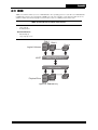
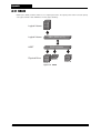
U320 SCSI to SATAII
4G Fibre to SAS
SAS to SAS
iSCSI to SAS
Disk Array Systems
Version 1.1
U320 SCSI to SATA II
4G Fibre to SAS
SAS to SAS
iSCSI to SAS
Model:
SA-8850S, SA-4551S, SA-6651S, SA-6651E, SS-4551E, SS-4552E, SS-6651E,
SS-6652E, SS-4501E/R, SS-6601E/R, SS-8801E/R, TS-4801R, SS-4502E/R,
SS-6602E/R, SS-8802E/R, SS-4503E/R, SS-6603E/R
JanusRAID II Generic Software Manual
Contents
Table of Contents
Chapter 1: Introduction
1.1 Overview .................................................................................................................................. 1-1
1.2 Key Features ............................................................................................................................ 1-2
1.3 How to Use This Manual .......................................................................................................... 1-7
1.4 RAID Structure Overview ......................................................................................................... 1-8
1.5 User Interfaces to Manage the RAID System ........................................................................ 1-10
1.6 Initially Configuring the RAID System .................................................................................... 1-11
1.7 Maintaining the RAID System ................................................................................................ 1-14
Chapter 2: Using the RAID GUI
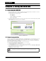
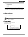
2.1 Accessing the RAID GUI .......................................................................................................... 2-1
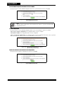
2.1.1 Browser Language Setting .............................................................................................. 2-1
2.1.2 Multiple System Viewer ................................................................................................... 2-3
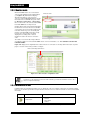
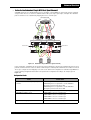
2.2 Monitor Mode ........................................................................................................................... 2-5
2.2.1 HDD state ........................................................................................................................ 2-6
2.2.2 Information icons ............................................................................................................. 2-7
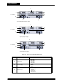
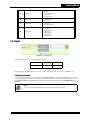
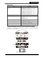
2.2.3 Rear side view ................................................................................................................. 2-9
2.2.4 Login .............................................................................................................................. 2-11
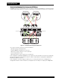
2.3 SAS JBOD Enclosure Display (for SAS expansion controller only) ....................................... 2-12
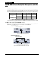
2.3.1 Rear side monitor of the SAS JBOD chassis ................................................................. 2-13
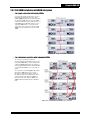
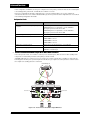
2.3.2 SAS JBOD Installation with RAID subsystem ................................................................ 2-13
2.3.3 Monitor mode ................................................................................................................. 2-16
2.3.4 Information icons ........................................................................................................... 2-17
2.3.5 SAS/SATA HDD information .......................................................................................... 2-17
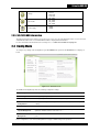
2.4 Config Mode ........................................................................................................................... 2-18
2.5 Quick Setup ........................................................................................................................... 2-19
2.5.1 Performance profile ....................................................................................................... 2-19
2.5.2 RAID setup .................................................................................................................... 2-20
2.6 RAID Management ................................................................................................................ 2-21
2.6.1 Hard disks ...................................................................................................................... 2-21
2.6.2 JBOD ............................................................................................................................. 2-23
2.6.3 Disk groups .................................................................................................................... 2-25
2.6.4 Logical disks .................................................................................................................. 2-27
2.6.5 Volumes ......................................................................................................................... 2-31
2.6.6 Snapshot Volumes ......................................................................................................... 2-34
2.6.7 Storage provisioning ...................................................................................................... 2-36
2.7 Maintenance Utilities .............................................................................................................. 2-43
2.7.1 Expanding disk groups .................................................................................................. 2-43
2.7.2 Defragmenting disk groups ............................................................................................ 2-43
2.7.3 Changing RAID level / stripe size for logical disks ......................................................... 2-44
2.7.4 Expanding the capacity of logical disks in a disk group ................................................. 2-45
2.7.5 Shrinking logical disks ................................................................................................... 2-46
2.7.6 Expanding volumes ....................................................................................................... 2-46
2.7.7 Shrinking volumes ......................................................................................................... 2-47
2.7.8 Cloning hard disks ......................................................................................................... 2-47
2.7.9 Scrubbing ....................................................................................................................... 2-49
2.7.10 Regenerating the parity ............................................................................................... 2-50
2.7.11 Performing disk self test .............................................................................................. 2-50
vii
Contents
2.7.12 Array roaming .............................................................................................................. 2-51
2.7.13 Array recovery ............................................................................................................. 2-52
2.7.14 Schedule task .............................................................................................................. 2-54
2.7.15 Cache Configurations .................................................................................................. 2-54
2.7.16 Miscellaneous .............................................................................................................. 2-55
2.8 Hardware Configurations ....................................................................................................... 2-56
2.8.1 Hard disks ...................................................................................................................... 2-56
2.8.2 FC/SAS/SCSI/iSCSI ports ............................................................................................. 2-59
2.8.3 COM port ....................................................................................................................... 2-60
2.9 Event Management ................................................................................................................ 2-61
2.9.1 Setting up the SMTP ...................................................................................................... 2-61
2.9.2 Setting up the SNMP ..................................................................................................... 2-62
2.9.3 Event logs ...................................................................................................................... 2-64
2.9.4 UPS ............................................................................................................................... 2-66
2.9.5 Miscellaneous ................................................................................................................ 2-67
2.10 System Management ........................................................................................................... 2-68
2.10.1 Restoring to factory settings ........................................................................................ 2-68
2.10.2 NVRAM configuration .................................................................................................. 2-68
2.10.3 Setting up the network ................................................................................................. 2-70
2.10.4 System Time ................................................................................................................ 2-71
2.10.5 Security control ............................................................................................................ 2-72
2.10.6 System information ...................................................................................................... 2-73
2.10.7 Battery backup module ................................................................................................ 2-73
2.10.8 Update system firmware, boot code and external enclosure F/W ............................... 2-74
2.10.9 Restart or halt the controller ........................................................................................ 2-74
2.10.10 Miscellaneous ............................................................................................................ 2-75
2.11 Performance Management .................................................................................................. 2-76
2.11.1 Hard disks .................................................................................................................... 2-76
2.11.2 Cache .......................................................................................................................... 2-76
2.11.3 LUN .............................................................................................................................. 2-77
2.11.4 Storage port ................................................................................................................. 2-78
Chapter 3: Using the LCD Console
3.1 Starting LCD Manipulation ....................................................................................................... 3-1
3.1.1 Confirm password ............................................................................................................ 3-1
3.2 LCD Messages ........................................................................................................................ 3-2
3.2.1 LCD layout ....................................................................................................................... 3-2
3.2.2 Status info ........................................................................................................................ 3-3
3.2.3 Emergent info .................................................................................................................. 3-4
3.2.4 Background task messages ............................................................................................. 3-4
3.2.5 Hotkeys ............................................................................................................................ 3-5
3.3 Menu ........................................................................................................................................ 3-6
3.3.1 Menu Tree ....................................................................................................................... 3-6
3.3.2 Creating an Array ............................................................................................................. 3-6
3.3.3 Network Settings .............................................................................................................. 3-7
3.3.4 Terminal Port Settings ..................................................................................................... 3-7
3.3.5 System Settings ............................................................................................................... 3-8
3.3.6 System Information .......................................................................................................... 3-8
Chapter 4: Using the CLI Commands
4.1 Overview .................................................................................................................................. 4-1
viii
Contents
4.1.1 Embedded CLI ................................................................................................................. 4-1
4.1.2 Conventions Overview ..................................................................................................... 4-6
4.2 Basic RAID Management ......................................................................................................... 4-7
4.2.1 Hard disks ........................................................................................................................ 4-7
4.2.2 JBOD disks ...................................................................................................................... 4-7
4.2.3 Disk groups ...................................................................................................................... 4-8
4.2.4 Spare and rebuild ............................................................................................................ 4-9
4.2.5 Logical disks .................................................................................................................. 4-10
4.2.6 RAID algorithms options ................................................................................................ 4-10
4.2.7 Volumes ......................................................................................................................... 4-11
4.2.8 Cache ............................................................................................................................ 4-12
4.3 RAID Maintenance Utilities .................................................................................................... 4-13
4.3.1 RAID attributes reconfiguration utilities .......................................................................... 4-13
4.3.2 Data integrity maintenance utilities ................................................................................ 4-14
4.3.3 Task priority control ....................................................................................................... 4-15
4.3.4 Task schedule management .......................................................................................... 4-15
4.3.5 On-going task monitoring ............................................................................................... 4-16
4.3.6 Array and volume roaming ............................................................................................. 4-16
4.3.7 Array recovery utilities ................................................................................................... 4-17
4.4 Storage Presentation ............................................................................................................. 4-17
4.4.1 Hosts .............................................................................................................................. 4-17
4.4.2 Host groups ................................................................................................................... 4-18
4.4.3 Storage groups .............................................................................................................. 4-19
4.4.4 Presentation planning .................................................................................................... 4-20
4.4.5 Selective storage presentation ...................................................................................... 4-20
4.4.6 Simple storage presentation .......................................................................................... 4-21
4.4.7 Symmetric-LUN storage presentation ............................................................................ 4-21
4.5 Hardware Configurations and Utilities .................................................................................... 4-22
4.5.1 Generic hard disk ........................................................................................................... 4-22
4.5.2 SAS ports ...................................................................................................................... 4-24
4.5.3 SCSI ports ..................................................................................................................... 4-24
4.5.4 FC ports ......................................................................................................................... 4-25
4.5.5 Management network interface ..................................................................................... 4-26
4.5.6 Local terminal ports ....................................................................................................... 4-27
4.5.7 Enclosure ....................................................................................................................... 4-28
4.5.8 Uninterruptible power supply ......................................................................................... 4-28
4.6 Performance management .................................................................................................... 4-29
4.6.1 Hard disks ...................................................................................................................... 4-29
4.6.2 Cache ............................................................................................................................ 4-29
4.6.3 LUN ................................................................................................................................ 4-29
4.6.4 Storage ports ................................................................................................................. 4-30
4.7 Redundant Controller Configurations ..................................................................................... 4-31
4.7.1 Mirrored write cache control .......................................................................................... 4-31
4.7.2 Change preferred controller ........................................................................................... 4-31
4.7.3 Path failover alert delay ................................................................................................. 4-31
4.8 Event Management ................................................................................................................ 4-31
4.8.1 NVRAM event logs ........................................................................................................ 4-31
4.8.2 Event notification ........................................................................................................... 4-32
4.8.3 Event handling ............................................................................................................... 4-33
4.9 System Management ............................................................................................................. 4-34
ix
Contents
4.9.1 Configurations management .......................................................................................... 4-34
4.9.2 Time management ......................................................................................................... 4-35
4.9.3 Administration security control ....................................................................................... 4-36
4.9.4 System information ........................................................................................................ 4-37
4.9.5 Miscellaneous ................................................................................................................ 4-37
4.10 Miscellaneous Utilities .......................................................................................................... 4-39
4.10.1 Lookup RAID systems ................................................................................................. 4-39
4.10.2 Turn on/off CLI script mode ......................................................................................... 4-39
4.10.3 Get command list and usage ....................................................................................... 4-39
4.11 Configuration shortcuts ........................................................................................................ 4-39
4.11.1 RAID quick setup ......................................................................................................... 4-39
4.11.2 Performance profile ..................................................................................................... 4-40
4.12 Snapshot ............................................................................................................................ 4-40
Chapter 5: Advanced Functions
5.1 Multi-Path IO Solutions ............................................................................................................ 5-1
5.1.1 Overview .......................................................................................................................... 5-1
5.1.2 Benefits ............................................................................................................................ 5-1
5.1.3 Configuring MPIO Hosts and RAID Controller ................................................................. 5-2
5.1.4 Windows Multi-Path Solution: PathGuard ........................................................................ 5-7
5.1.5 Linux Multi-Path Solution ............................................................................................... 5-12
5.1.6 MAC Multi-Path Solution ................................................................................................ 5-16
5.1.7 VMware ESX Server Multi-Path Solution ....................................................................... 5-16
5.1.8 Sun Solaris 10 OS Multi-Path Solution .......................................................................... 5-17
5.2 Multiple ID solutions ............................................................................................................... 5-18
5.2.1 Overview ........................................................................................................................ 5-18
5.3 Redundant Controller ............................................................................................................. 5-21
5.3.1 Overview ........................................................................................................................ 5-21
5.3.2 Controller Data Synchronization .................................................................................... 5-23
5.3.3 Redundant-Controller System Configuration with MPIO ............................................... 5-25
5.3.4 Controller and Path Failover/Failback Scenarios ........................................................... 5-34
5.4 Snapshot ................................................................................................................................ 5-38
5.4.1 Introduction .................................................................................................................... 5-38
5.4.2 How Snapshot Works .................................................................................................... 5-39
5.4.3 How to Use Snapshots .................................................................................................. 5-41
5.4.4 Snapshot Utility and Scripting ........................................................................................ 5-45
5.5 Dynamic Capacity Management ............................................................................................ 5-48
5.5.1 Free chunk defragmentation .......................................................................................... 5-50
5.5.2 Logical disk shrink ......................................................................................................... 5-51
5.5.3 Logical disk expansion ................................................................................................... 5-52
5.5.4 Disk group expansion .................................................................................................... 5-53
5.5.5 Volume expansion and shrink ........................................................................................ 5-54
5.5.6 Windows DiskPart Utility ................................................................................................ 5-55
5.6 RAIDGuard Central ................................................................................................................ 5-58
5.6.1 Introduction .................................................................................................................... 5-58
5.6.2 Deployment Overview .................................................................................................... 5-59
5.6.3 Installing the RAIDGuard Central .................................................................................. 5-61
5.6.4 Uninstalling the RAIDGuard Central .............................................................................. 5-62
5.6.5 Launching the RAIDGuard Central ................................................................................ 5-62
5.6.6 RGC GUI Overview ....................................................................................................... 5-65
x
Contents
5.6.7 RAID System Registration ............................................................................................. 5-67
5.6.8 RAID System Monitoring ............................................................................................... 5-71
5.6.9 Configuring MSN Event Notification .............................................................................. 5-72
5.7 VDS Provider ......................................................................................................................... 5-73
5.7.1 Overview ........................................................................................................................ 5-73
5.7.2 Installing the VDS Provider ............................................................................................ 5-74
5.7.3 Uninstalling the VDS Provider ....................................................................................... 5-74
5.7.4 Using the VDS Provider Configuration Utility ................................................................. 5-74
5.7.5 VDS-Based RAID Management Software ..................................................................... 5-76
Chapter 6: Troubleshooting
6.1 General Guidelines .................................................................................................................. 6-1
6.2 Beeper ..................................................................................................................................... 6-1
6.3 Performance Tuning ................................................................................................................ 6-2
6.4 Hard Disks ............................................................................................................................... 6-5
6.5 User Interfaces ......................................................................................................................... 6-7
6.6 RAID Configuration and Maintenance ..................................................................................... 6-8
6.7 Redundant Controller and MPIO ............................................................................................ 6-10
Appendix A: Understanding RAID
A.1 RAID Overview ........................................................................................................................A-1
A.2 RAID 0 .....................................................................................................................................A-3
A.3 RAID 1 .....................................................................................................................................A-4
A.4 RAID 3 .....................................................................................................................................A-5
A.5 RAID 5 .....................................................................................................................................A-6
A.6 RAID 6 .....................................................................................................................................A-7
A.7 RAID 10 ...................................................................................................................................A-8
A.8 RAID 30 ...................................................................................................................................A-9
A.9 RAID 50 .................................................................................................................................A-10
A.10 RAID 60 ...............................................................................................................................A-11
A.11 JBOD ...................................................................................................................................A-12
A.12 NRAID .................................................................................................................................A-13
Appendix B: Features and Benefits
B.1 Overview ..................................................................................................................................B-1
B.2 Flexible Storage Presentation .................................................................................................B-1
B.3 Flexible Storage Provisioning ..................................................................................................B-2
B.4 Comprehensive RAID Configurations ......................................................................................B-3
B.5 Dynamic Configuration Migration ............................................................................................B-4
B.6 Effective Capacity Management ..............................................................................................B-5
B.7 Adaptive Performance Optimization ........................................................................................B-6
B.8 Proactive Data Protection ........................................................................................................B-8
B.9 Fortified Reliability and Robustness ........................................................................................B-9
B.10 Vigilant System Monitoring ..................................................................................................B-11
B.11 Convenient Task Management ............................................................................................B-12
B.12 Extensive Supportive Tools .................................................................................................B-13
B.13 Easy-To-Use User Interfaces ..............................................................................................B-14
Appendix C: Boot Utility
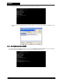
C.1 (N) Set IP address .................................................................................................................. C-2
C.2 (L) Load Image by TFTP ........................................................................................................ C-3
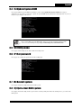
C.3 (B) Update Boot ROM ............................................................................................................ C-4
xi
Contents
C.4 (S) Update System ROM ........................................................................................................ C-4
C.5 (H) Utility menu ....................................................................................................................... C-5
C.6 (P) Set password .................................................................................................................... C-5
C.7 (R) Restart system ................................................................................................................. C-5
C.8 (Q) Quit & Boot RAID system ................................................................................................. C-5
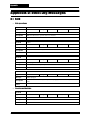
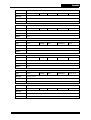
Appendix D: Event Log Messages
D.1 RAID ....................................................................................................................................... D-1
D.2 Task ........................................................................................................................................ D-8
D.3 Disk ...................................................................................................................................... D-25
D.4 Host ports ............................................................................................................................. D-37
D.5 Controller hardware .............................................................................................................. D-48
D.6 Enclosure ............................................................................................................................. D-51
D.7 System ................................................................................................................................. D-59
D.8 Network ................................................................................................................................ D-67
D.9 Miscellaneous ....................................................................................................................... D-68
D.10 Snapshot ........................................................................................................................... D-68
xii
Contents
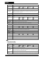
List of Tables
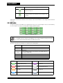
Table 2-1
Buttons in monitor and config mode ....................................................................... 2-6
Table 2-2
Hard disk code ....................................................................................................... 2-6
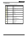
Table 2-4
Information icons .................................................................................................... 2-7
Table 2-3
Hard disks tray color ............................................................................................... 2-7
Table 2-5
Components at the rear side of the system .......................................................... 2-10
Table 2-6
Login usernames and passwords ......................................................................... 2-11
Table 2-7
Supported number of redundant SAS JBOD chassis and hard disks .................. 2-12
Table 2-8
Information icons (in SAS monitor mode) ............................................................. 2-17
Table 2-9
Performance profile values ................................................................................... 2-19
Table 2-10
Hard disk information ........................................................................................... 2-21
Table 2-11
Limitations of the number of member disks .......................................................... 2-44
Table 2-12
State transition ..................................................................................................... 2-53
Table 3-1
List of status messages .......................................................................................... 3-3
Table 3-2
List of emergent messages .................................................................................... 3-4
Table 3-3
List of background task messages ......................................................................... 3-5
Table 5-1
MPIO device information ...................................................................................... 5-10
Table 5-2
System status information .................................................................................... 5-69
Table 6-1
The capacity correlated with sector size ................................................................ 6-9
xiv
Contents
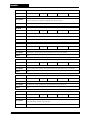
List of Figures
xv
Figure 1-1
Layered storage objects ....................................................................................... 1-8
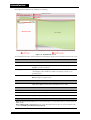
Figure 2-1
GUI login screen ................................................................................................... 2-1
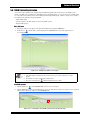
Figure 2-2
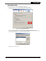
Setting the language in Firefox ............................................................................. 2-2
Figure 2-3
Languages dialog (Firefox) ................................................................................... 2-3
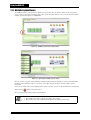
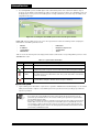
Figure 2-4
Multiple system viewer (side button) .................................................................... 2-3
Figure 2-5
Opening the multiple system viewer ..................................................................... 2-4
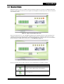
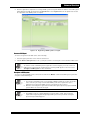
Figure 2-6
Single controller GUI monitor mode ..................................................................... 2-5
Figure 2-7
Redundant-controller system GUI monitor monitor mode .................................... 2-5
Figure 2-8
HDD Tray (GUI) .................................................................................................... 2-6
Figure 2-9
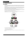
Rear side of the RAID system (GUI) .................................................................... 2-9
Figure 2-10
Rear side of the redundant fiber RAID system ................................................... 2-10
Figure 2-11
Rear side of the redundant SAS RAID system ................................................... 2-10
Figure 2-12
Login section ...................................................................................................... 2-11
Figure 2-13
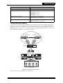
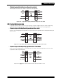
Rear side of the SAS JBOD chassis (GUI) ........................................................ 2-13
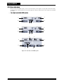
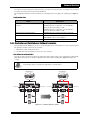
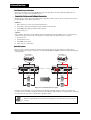
Figure 2-14
Single SAS JBOD connection ............................................................................ 2-14
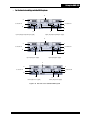
Figure 2-15
Redundant SAS JBOD loop connection ............................................................ 2-15
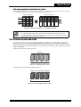
Figure 2-16
SAS enclosure monitor mode ............................................................................. 2-16
Figure 2-17
SAS enclosure configuration mode .................................................................... 2-16
Figure 2-18
Overview screen ................................................................................................. 2-18
Figure 2-19
Method switching message ................................................................................ 2-36
Figure 2-20
Simple storage ................................................................................................... 2-37
Figure 2-21
Symmetric storage ............................................................................................. 2-38
Figure 2-22
Selective storage ................................................................................................ 2-40
Figure 2-23
Specify the percentage for Bad Block Alert ........................................................ 2-58
Figure 2-24
Specify the percentage for Bad Block Clone ...................................................... 2-58
Figure 2-25
Event log download message ............................................................................ 2-65
Figure 2-26
Options in the Configurations screen-1
(System Management menu) ............................................................................. 2-68
Figure 2-27
Options in the Configurations screen-2
(System Management menu) ............................................................................. 2-69
Figure 2-28
Options in the Configurations screen-3
(System Management menu) ............................................................................. 2-69
Figure 2-29
Options in the Configurations screen-4
(System Management menu) ............................................................................. 2-70
Figure 3-1
LCD manipulation procedure ................................................................................ 3-1
Figure 3-2
Menu tree ............................................................................................................. 3-6
Figure 4-1
Interfaces to Access CLI ...................................................................................... 4-1
Figure 5-1
Dual independent MPIO hosts ............................................................................. 5-4
Figure 5-2
Clustered server environment .............................................................................. 5-6
Figure 5-3
Computer Management screen: Device Manager ................................................ 5-9
Figure 5-4
MPIO device screen ........................................................................................... 5-10
Figure 5-5
MTID environment .............................................................................................. 5-19
Figure 5-6
Redundant Single MPIO host (dual channel) ..................................................... 5-25
Contents
Figure 5-7
Redundant Single MPIO host (quad channel) .................................................... 5-27
Figure 5-8
Redundant Dual Independent MPIO hosts ......................................................... 5-29
Figure 5-9
Dual clustering MPIO hosts ................................................................................ 5-31
Figure 5-10
Active-Passive Redundant Single MPIO host .................................................... 5-33
Figure 5-11
Controller failover scenario ................................................................................. 5-35
Figure 5-12
Controller failover scenario ................................................................................. 5-36
Figure 5-13
Controller failover and the page redirection message ........................................ 5-37
Figure 5-14
Controller failback message ............................................................................... 5-37
Figure 5-15
Error message indicates both controller failures ................................................ 5-37
Figure 5-16
Relationship of volumes ..................................................................................... 5-40
Figure 5-17
SAN Environment ............................................................................................... 5-46
Figure 5-18
Defragment a disk group to expand the last free chunk ..................................... 5-51
Figure 5-19
Defragment a disk group to consolidate free chunks ......................................... 5-51
Figure 5-20
Logical disk capacity shrink and expanding an adjacent free chunk .................. 5-52
Figure 5-21
Logical disk capacity shrink and creating a new free chunk ............................... 5-52
Figure 5-22
Logical disk capacity expansion by allocating an adjacent free chunk ............... 5-52
Figure 5-23
Logical disk capacity expansion by moving logical disks to a free chunk .......... 5-53
Figure 5-24
Logical disk capacity expansion by allocating an adjacent free chunk and moving
logical disks ........................................................................................................ 5-53
Figure 5-25
Disk group expansion by adding new member disks and enlarging the last free chunk
5-54
Figure 5-26
Disk group expansion by adding new member disks and creating a new free chunk
5-54
Figure 5-27
Disk group expansion to consolidate free chunks .............................................. 5-54
Figure 5-28
Striping member volumes ................................................................................... 5-55
Figure 5-29
Concatenating member volumes ........................................................................ 5-55
Figure 5-30
Concatenated striping member volumes ............................................................ 5-55
Figure 5-31
Deployment example of RAIDGuard Central components ................................. 5-60
Figure 5-32
RGC Server monitor screen ............................................................................... 5-63
Figure 5-33
RGC Agent monitor screen ................................................................................ 5-64
Figure 5-34
RGC GUI main screen ....................................................................................... 5-65
Figure 5-35
Adding the IP address of an agent ..................................................................... 5-67
Figure 5-36
Scanning the online RAID systems in the specified IP range ............................ 5-68
Figure 5-37
Scanning the online RAID systems in the selected agent’s domain .................. 5-68
Figure 5-38
Registering a RAID system to an agent ............................................................. 5-70
Figure 5-39
RGC GUI - System Panel ................................................................................... 5-71
Figure 5-40
VDS Provider illustration .................................................................................... 5-73
Figure 5-41
VDS Provider Configure screen ......................................................................... 5-75
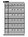
Figure A-1
RAID 0 disk array .................................................................................................A-3
Figure A-2
RAID 1 disk array .................................................................................................A-4
Figure A-3
RAID 3 disk array .................................................................................................A-5
Figure A-4
RAID 5 disk array .................................................................................................A-6
Figure A-5
RAID 6 disk array .................................................................................................A-7
Figure A-6
RAID 10 disk array ...............................................................................................A-8
xvi
Contents
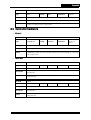
Figure A-7
RAID 30 disk array ...............................................................................................A-9
Figure A-8
RAID 50 disk array .............................................................................................A-10
Figure A-9
RAID 60 disk array .............................................................................................A-11
Figure A-10
JBOD disk array .................................................................................................A-12
Figure A-11
NRAID ................................................................................................................A-13
xvii
Preface
About this manual
Congratulations on your purchase of the product. This controller allows you to control your RAID system through a userfriendly GUI, which is accessed through your web browser.
This manual is designed and written for users installing and using the RAID controller. The user should have a good
working knowledge of RAID planning and data storage.
Symbols used in this manual
This manual highlights important information with the following icons:
Caution
This icon indicates the existence of a potential hazard that could result in personal injury, damage
to your equipment or loss of data if the safety instruction is not observed.
Note
This icon indicates useful tips on getting the most from your RAID controller.
iii
Introduction
Chapter 1: Introduction
Congratulations on your purchase of our RAID controller. Aiming at serving versatile applications, the RAID controller
ensures not only data reliability but also improves system availability. Supported with cutting-edge IO processing
technologies, the RAID controller delivers outstanding performance and helps to build dependable systems for heavyduty computing, workgroup file sharing, service-oriented enterprise applications, online transaction processing,
uncompressed video editing, or digital content provisioning. With its advanced storage management capabilities, the
RAID controller is an excellent choice for both on-line and near-line storage applications. The following sections in this
chapter will present an overview of features of the RAID controller, and for more information about its features and
benefits, please see Appendix B.
1.1 Overview
•
Seasoned Reliability
The RAID controller supports various RAID levels, 0, 1, 3, 5, 6, and including multi-level RAID, like RAID 10, 30, 50, and
60, which perfectly balances performance and reliability. To further ensure the long-term data integrity, the controller
provides extensive maintenance utilities, like periodic SMART monitoring, disk cloning, and disk scrubbing to proactively
prevent performance degradation or data loss due to disk failure or latent bad sectors.
The controller also supports multi-path I/O (MPIO) solutions tolerating path failure and providing load balance among
multiple host connections for higher availability and performance. Together with active-active redundant-controller
configuration, the RAID system offers high availability without single point of failure.
•
Great Flexibility and Scalability
Nowadays, IT staff is required to make the most from the equipments purchased, and thus easier sharing and better
flexibility is a must for business-class storage systems. The RAID controller allows different RAID configurations, like
RAID levels, stripe sizes, and caching policies, to be deployed independently for different logical units on single disk
group, such that the storage resources can be utilized efficiently by fulfilling different requirements.
As business grows or changes during the lifetime of storage systems, the requirements are very likely to be changed, and
the users need to reconfigure the system to support the business dynamics while maintaining normal operations. The
RAID controller allows capacity expansion by adding more disk drives or expansion chassis. Comprehensive online
reconfiguration utilities are available for migration of RAID level and stripe size, volume management, capacity resizing,
and free space management.
•
Outstanding Performance
The RAID controller delivers outstanding performance for both transaction-oriented and bandwidth-hungry applications.
Its superscalar CPU architecture with L2 cache enables efficient IO command processing, while its low-latency system
bus streamlines large-block data transfer.
In addition to the elaborated RAID algorithms, the controller implements also sophisticated buffer caching and IO
scheduling intelligence. Extensive IO statistics are provided for monitoring the performance and utilization of storage
devices. Users can online adjust the optimization policy of each LUN based on the statistics to unleash the most power of
the controller.
•
Comprehensive and Effortless Management
Users can choose to manage the RAID systems from a variety of user interfaces, including command line interface over
local console and secure shell (SSH), LCD panel, and web-based graphical user interface (GUI). Events are recorded on
the NVRAM, and mail is sent out to notify the users without installing any software or agents. Maintenance tasks like
capacity resizing and disk scrubbing are online executable, and can be scheduled or periodically executed. With the
comprehensive management utilities, users can quickly complete the configurations and perform reconfiguration
effortlessly.
1-1
Introduction
1.2 Key Features
•
Basic RAID Construction
• Multiple RAID levels: 0, 1, 3, 5, 6, 10, 30, 50, 60, JBOD, and NRAID
• Multiple stripe sizes (KB): 4, 8, 16, 32, 64, 128, 256, and 512.
• Independently-selectable strip size for each logical disk
• Independently-selectable RAID level for each logical disk
• Support Quick Setup for effortless and quick RAID configuration
• Support hot spare with global spare and local spare
• Support auto spare and spare restore options
• Support auto online disk rebuilding and configurable rebuild modes
• Multiple disk rebuilding modes: parallel, sequential, and prioritized
• Support up to 8 disk groups and 32 logical disks per disk group
• Support up to 24 disks in one chassis and totally 64 drives with expansion units
•
Volume management
• Support striping volume for performance enhancement
• Support concatenating volume for large-capacity LUN
• Support concatenated striping volume
• Online volume capacity expansion
• Online volume capacity shrink
• Support up to 32 volumes and 8 logical disks per volume
•
Augmented RAID Features
• Flexible free chunk management
• Multiple RAID initializations: none, regular (write-zero), and background
• Support disk group write-zero initialization
• Support user-configurable disk group capacity truncation
• Support alignment offset
• Support intelligent computation for RAID data and parity
• Support fast read I/O response
• Support NVRAM-based write log and auto parity consistency recovery
• Support online bad block recovery and reallocation
• Support battery backup module (BBM) for data retention during no power
•
Caching and Performance Optimizations
• Selective cache unit sizes (KB): 4, 8, 16, 32, 64, and 128
• Independently-selectable caching policies for each LUN
• Selective pre-read options with pre-read depth
• Adaptive pre-read algorithms for sequential read workload
• Selective write caching policies: write-through and write-behind (delay write)
• Selective cache flush period with manual flush utility
• Support intelligent write I/O merging and sorting algorithms
• Support intelligent disk I/O scheduling
• Selective performance profile: AV streaming, Max IOPS, and Max throughput
•
RAID Reconfiguration Utilities
• Online disk group expansion
• Online RAID level migration
• Online stripe size migration
• Online simultaneous execution of the operations above
• Online disk group defragmentation for free space consolidation
1-2
Introduction
• Online simultaneous disk group expansion and defragmentation
• Online logical disk capacity expansion
• Online logical disk capacity shrink
• Support rebuild-first policy for early recovery from RAID degradation
•
Data Integrity Maintenance Utilities
• Online logical disk parity regeneration
• Online disk scrubbing (a.k.a. media scan or patrol read)
• Online parity check and recovery
• Online disk cloning and replacement, with automatic resuming cloning
• Support skipping cloned sectors when rebuilding partially cloned disks
•
Background Task Management
• Background task progress monitoring
• Support one-time or periodic scheduling of maintenance tasks
• Support priority control for different types of background tasks, like rebuilding
• Support manual abort background tasks
• Support background task roaming
• Support automatic resuming tasks when the system restarts
• Support early notification of task completion
•
Array Roaming and Recovery
• Support Configuration on disk (COD) with unique ID for each disk drive
• Support drive traveling
• Support online and offline array roaming
• Support automatic and manual roaming conflict resolution
• Online array recovery for logical disks, disk groups, and volumes
•
Storage Presentation
• Support multiple storage presentations: simple, symmetric, and selective
• Support dynamic LUN masking
• Independently-selectable access control for each host and LUN
• Independently-selectable CHS geometry and sector size for each LUN
• Support host grouping management
• Support up to 32 hosts, 16 host groups, and 32 storage groups
• Support up 1024 LUNs and 128 LUNs per storage group
•
Hard Disk Management
• Support hard disk adding and removal emulation utility
• Support disk self test (DST) and disk health monitoring by SMART
• Support SMART warning-triggered disk cloning
• Support bad block over-threshold triggered disk cloning
• Support disk cache control
• Support disk auto standby when idle
• Support disk and disk group visual identification by LED
• Support disk sequential power-on
• Extensive disk I/O parameters selective for different environments
•
Expansion Port Functions (model-dependent)
• Support SAS JBOD expansion units
• Support SAS SMP and SAS STP protocols
• Support external enclosure monitoring by SES
• Selective external enclosure and disk polling period
1-3
Introduction
•
Host Interface Functions (model-dependent)
• Support 4Gb/s Fibre Channel host interfaces (FC-SAS/SATA controller)
• Support 3Gb SAS host interfaces (SAS-SAS controller)
• Support Ultra320 SCSI host interfaces (SCSI-SATA controller)
• Support T11 SM-HBA attributes statistics
• Support multiple-path IO (MPIO) solutions
•
Management Interfaces
• Local management via RS-232 port and LCD panel
• Remote management via Ethernet and TCP/IP
• Support network address settings by static, DHCP, and APIPA
• Support web-based GUI via embedded web server (HTTP)
• Support multiple languages and on-line help on web GUI
• Web-based multiple RAID system viewer with auto system discovery
• Embedded Command Line Interface (CLI) via RS232 port, SSH, and telnet
• Host-side Command Line Interface (CLI) via FC/SAS/SCSI and TCP/IP
• Support in-band and out-of-band RAID management
• Support SSL for protecting management sessions over Internet
• Support RAIDGuard™ Central for remote centralized management
•
System Monitoring Functions
• Support monitoring and control of hardware components and chassis units
• Support SMART UPS monitoring and alert over RS232 port
• NVRAM-based event logging with severity level
• Event notification via beeper, email (SMTP), and SNMP trap (v1 and V2c)
• Selective event logging and notification by severity level
• Support redundant multiple email server and SNMP agents
• Support multiple event recipients of email and SNMP trap
• Support SNMP GET commands for monitoring via SNMP manager
•
Redundant Controller Functions (model-dependent)
• Support dual active-active controller configuration
• Online seamless controller failover and failback
• Cache data mirroring with on/off control option
• Auto background task transfer during controller failover and failback
• Support simultaneous access to single disk drive by two controllers
• Online manual transfer preferred controller of a virtual disk
• Uninterrupted system firmware upgrade
•
Snapshot Functions (model-dependent)
• Support copy-on-write compact snapshot
• Instant online copy image creation and export
• Instant online data restore/rollback from snapshot
• Support multiple active snapshots for single LUN
• Support read/writable snapshot
• Support spare volume for overflow
• Support online snapshot volume expansion
• Support snapshot configuration roaming
•
Miscellaneous Supporting Functions
• Support configurations download and restore
• Support configurations saving to disks and restore
• Support password-based multi-level administration access control
1-4
Introduction
• Support password reminding email
• Time management by RTC and Network Time Protocol (NTP) with DST
• Support controller firmware upgrade (boot code and system code)
• Support dual flash chips for protecting and recovering system code
• Support object naming and creation-time logging
Note
The features may differ for different RAID system models and firmware version. You may need to
contact your RAID system supplier to get the updates.
1.3 How to Use This Manual
This manual is organized into the following chapters:
• Chapter 1 (Introduction) provides a feature overview of the RAID system, and some basic guidelines for managing the
RAID system.
• Chapter 2 (Using the RAID GUI) describes how to use the embedded GUI for monitoring and configurations with
information helping you to understand and utilize the features.
• Chapter 3 (Using the LCD Console) presents the operations of LCD console, which helps you to quickly get
summarized status of the RAID system and complete RAID setup using pre-defined configurations.
• Chapter 4 (Using the CLI Commands) tabulates all the CLI commands without much explanation. Because there is no
difference in functions or definitions of parameters between GUI and CLI, you can study the GUI chapter to know how
a CLI command works.
• Chapter 5 (Advanced Functions) provides in-depth information about the advanced functions of the RAID system to
enrich your knowledge and elaborate your management tasks.
• Chapter 6 (TroubleShooting) provides extensive information about how you can help yourself when encoutering any
troubles.
• Appendices describe supporting information for your references.
If you are an experienced user, you may quickly go through the key features to know the capabilities of the RAID system,
and then read only the chapters for the user interfaces you need. Because this RAID system is designed to follow the
commonly-seen conventions in the industry, you will feel comfortable when dealing with the setup and maintenance
tasks. However, there are unique features offered only by the RAID system, and the RAID systems may be shipped with
new features. Fully understanding these features will help you do a better job.
If you are not familiar with RAID systems, you are advised to read all the chapters to know not only how to use this RAID
system but also useful information about the technologies and best practices. A better starting point for your
management tasks is to get familiar with the GUI because of its online help and structured menu and web pages. You
also need to know the LCD console because it is the best way for you to have a quick view of the system’s health
conditions. If you live in an UNIX world, you probably like to use the CLI to get things done more quickly.
To avoid having an ill-configured RAID system, please pay attentions to the warning messages and tips in the manual
and the GUI. If you find mismatch between the manual and your RAID system, or if you are unsure of anything, please
contact your suppliers.
1-5
Introduction
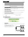
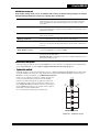
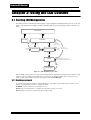
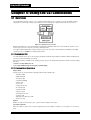
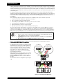
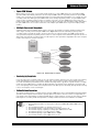
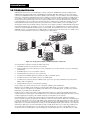
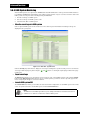
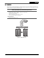
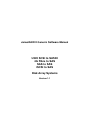
1.4 RAID Structure Overview
The storage resources are managed as storage
objects in a hierarchical structure. The hard disks, the
only physical storage objects in the structure, are the
essence of all other storage objects. A hard disk can
be a JBOD disk, a data disk of a disk group, or a local
spare disk of a disk group. It can also be an unused
disk or a global spare disk. The capacity of a disk
group is partitioned to form logical disks with different
RAID configurations, and multiple logical disks can be
put together to create volumes using striping,
concatenation, or both. The JBOD disks, logical disks,
and volumes, are virtual disks, which can be exported
to host interfaces as SCSI logical units (LUN) and
serve I/O access from the host systems. Below are
more descriptions about each storage objects.
•
Logical Units
Volumes
Logical Disks
Disk Groups
JBOD disk
A JBOD (Just a Bunch Of Disks) disk is formed by
single hard disk that can be accessed by hosts as a
LUN exported by the controller. The access to the
LUN is directly forwarded to the hard disk without any
address translation. It is often also named as pass-through disk.
•
Local
Spare
JBOD
Disks
Global
Spare
Unused
Disks
Hard Disks
Figure 1-1 Layered storage objects
Member disk
The hard disks in a disk group are member disks (MD). A member disk of a disk group can be a data disk or a local spare
disk. A data member disk provides storage space to form logical disks in a disk group.
•
Disk group
A disk group (DG) is a group of hard disks, on which logical disks can be created. Operations to a disk group are applied
to all hard disks in the disk group.
•
Logical disk
A logical disk (LD) is formed by partitioning the space of a disk group. Logical disks always use contiguous space, and
the space of a logical disk is evenly distributed across all member disks of the disk group. A logical disk can be exported
to hosts as a LUN or to form volumes.
•
Local spare and global spare disk
A spare disk is a hard disk that will automatically replace a failed disk and rebuild data of the failed disk. A local spare disk
is dedicated to single disk group, and a global spare disk is used for all disk groups. When a disk in a disk group fails, the
controller will try to use local spare disks first, and then global spare disks if no local spare is available.
•
Volume
A volume is formed by combining multiple logical disks using striping (RAID0) and concatenation (NRAID) algorithms.
Multiple logical disks form single volume unit using striping, and multiple volume units are aggregated to form a volume
using concatenation. A volume can be exported to hosts as a LUN.
•
Logical unit
A logical unit (LUN) is a logical entity within a SCSI target that receives and executes I/O commands from SCSI initiators
(hosts). SCSI I/O commands are sent to a target device and executed by a LUN within the target.
•
Virtual disk
A virtual disk is an storage entity that can service I/O access from LUNs or from other virtual disks. It could be JBOD disk,
logical disk, or volume. If a virtual disk is part of other virtual disk, then it cannot be exported to LUNs.
•
LUN mapping
A LUN mapping is a set of mapping relationships between LUNs and virtual disks in the controller. Computer systems
can access the LUNs presented by the controller after inquiring host ports of the controller.
1-6
Introduction
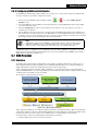
1.5 User Interfaces to Manage the RAID System
A variety of user interfaces and utilities are offered for managing the RAID systems, and you may choose to use one or
multiple of them that suit your management purposes. Introduction to these interfaces and utilities is described as below:
•
Web-based GUI (chapter 2)
Web-based GUI is accessed by web browsers after proper setup of the network interfaces. It offers an at-a-glance
monitoring web page and full-function system management capability in structured web pages. It is advised to use the
web-based GUI to fully unleash the power of RAID system if you are a first-time user.
•
SNMP Manager (section 2.9.2 Setting up the SNMP)
SNMP
SNMP (Simple Network Management Protocol) is a widely used protocol based on TCP/IP for monitoring the health of
network-attached equipments. The RAID controller is equipped with an embedded SNMP Agent to support SNMP-based
monitoring. You can use SNMP applications (SNMP v1 or v2c-compliant) at remote computers to get event notification by
SNMP traps and watch the status of a RAID system.
•
LCD Console (chapter 3)
LCD console is offered for quick configuration and for display of simplified information and alerting messages. It is mostly
for initializing network setting to bring up the web-based GUI or for knowing the chassis status. Using the LCD console for
configuration is only advised when you know clearly the preset configurations.
•
CLI Commands (chapter 4)
Command line interface can be accessed by RS-232 port, TELNET, or SSH. You can also use host-based CLI software
to manage RAID systems by in-band (FC/SAS/SCSI) or out-of-band (Ethernet) interfaces. It helps you to complete
configurations in a fast way since you can type in text commands with parameters quickly without the need to do browse
and click. You may also use CLI scripts for repeating configurations when deploying many systems.
•
RAIDGuard Central (chapter 5)
RAIDGuard Central is a software suite that helps you to manage multiple RAID systems installed in multiple networks. It
locates these systems by broadcasting and will be constantly monitoring them. It receives events from the systems, and
stores all the events to single database. It also provides event notification by MSN messages.
•
Microsoft VDS (chapter 5)
VDS is a standard of RAID management interface for Windows systems. The RAID system can be accessed by VDScompliant software after you install the corresponding VDS provider to your systems. This helps you to manage RAID
systems from different vendors using single software. But note because VDS is limited to general functions, you need to
use Web GUI or CLI for some advanced functions of this RAID system.
1.6 Initially Configuring the RAID System
Properly configuring your RAID systems helps you to get the most out of your investments on the storage hardware and
guarantee planned service level agreements. It also reduces your maintenance efforts and avoids potential problems that
might cause data loss or discontinued operations. It is especially true for a powerful and flexible RAID system like the one
you have now. This section provides some basic steps and guidelines for your reference. The initial configuration has the
following tasks:
1. Understanding your users’ needs and environments
2. Configuring the hardware settings and doing health check
3. Organizing and presenting the storage resources
4. Installing and launching bundled software (optionally)
5. Getting ready for future maintenance tasks
•
Understanding your users’ needs and environments
The first step for procuring or deploying any equipment is to know the users’ needs and environments, assuming you’ve
already known much about your RAID systems. Users’ needs include the capacity, performance, reliability, and sharing.
The environment information includes the applications, operating systems (standalone or clustered), host systems, host
adapters, switches, topologies (direct-attached or networked storage), disk drives (enterprise-class, near-line, or
desktop) and management networks. Extra cares are needed if you are installing the RAID systems to an existed
infrastructure under operations. Check your RAID system supplier to ensure good interoperability between the RAID
system and the components in your environments. You will also need to know the potential changes in the future, like
capacity growth rate or adding host systems, such that you can have plans for data migration and reconfigurations. The
quality of your configurations will largely depend on the information you collect. It is advised to write down the information
of users’ needs and environments as well as the configurations in your mind, which can be very helpful guidance through
the all the lifetime of the RAID systems.
1-7
Introduction
•
Configuring the hardware settings and doing health check
After installing your RAID systems with necessary components, like hard disks and transceivers, to your environment,
enabling the user interfaces is a prerequisite if you want to do anything useful to your RAID systems. The only user
interface that you can use without any tools is the LCD console, by which the settings of the RS232 port and the
management network interface can be done to allow you to use the GUI and CLI (see 3.3 Menu on page 3-5).
Now, do a quick health check by examining the GUI monitoring page to locate any mal-functioning components in the
chassis or suspicious events (section 2.2). Follow the hardware manual to do troubleshooting, if needed, and contact
your supplier if the problems still exist. Make sure the links of the host interfaces are up and all installed hard disks are
detected. Since your hard disks will be the final data repository, largely influencing the overall performance and reliability,
it is advised to use the embedded self-test utility and SMART functions to check the hard disks (see 2.8 Hardware
Configurations on page 2-38 ). A better approach would be to use benchmark or stress testing tools.
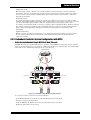
You need also be sure that all the attached JBOD systems are detected and no abnormal event reported for the
expansion port hardware (see 2.3 SAS JBOD Enclosure Display (for SAS expansion controller only) on page 2-11).
Sometimes, you will need to adjust the hardware parameters, under your supplier’s advices, to avoid potential
interoperability issues.
•
Organizing and presenting the storage resources
The most essential configuration tasks of a RAID system are to organize the hard disks using a variety of RAID settings
and volume management functions, and eventually to present them to host systems as LUNs (LUN mapping). This is a
process consisted of both top-down and bottom-up methodology. You see from high-level and logical perspectives of
each host system to define the LUNs and their requirements. On the other hand, you will do configuration starting from
the low-level and physical objects, like grouping the disk drives into disk groups.
Tradeoff analysis is required when choosing RAID levels, like using RAID 0 for good performance but losing reliability, or
using RAID 6 for high reliability but incurring performance penalty and capacity overhead. The appendix provides
information about the algorithms of each RAID level and the corresponding applications. You can also use the embedded
volume management functions to build LUNs of higher performance and larger capacity. The RAID system offers much
flexibility in configurations, like independently-configurable RAID attributes for each logical disk, such that capacity
overhead can be minimized while performance and reliability can still be guaranteed.
You might need to pay attentions to a few options when doing the tasks above, like initialization modes, cache settings,
alignment offset rebuilding mode, and etc. Please read the GUI chapter to know their meanings and choose the most
appropriate settings, because they are directly or indirectly related to how well the RAID system can perform (see 2.6
RAID Management on page 2-16 and 2.7.16 Miscellaneous on page 2-37).
Note
When planning your storage resources, reserving space for snapshot operations is needed. Please
check chapter 5 for information about the snapshot functions.
•
Installing and launching bundled software (optionally)
The RAID system is equipped with host-side software providing solutions for multi-path I/O, VDS-compliant management,
and centralized management console on multiple platforms. You can locate their sections in the chapter 5 and know their
features and benefits, as well as how to do the installation and configuration. Contact your RAID system supplier to know
the interoperability between the software and the system.
Note
Installing multi-path I/O driver is a must for redundant-controller systems to support controller
failover/failback. Please check Chapter 5: Advanced Functions for more information about MPIO
and redundant-controller solution.
•
Getting ready for future maintenance tasks
The better you’re prepared, the less your maintenance efforts would be. Below are the major settings you’ll need for
maintenance.
Event logging and notification
You can have peace only if you can always get timely notifications of incidents happening to your RAID systems, so
completing the event notification settings is also a must-do. You might also need to set the policies for event logging and
notifications (see 2.9 Event Management on page 2-44).
1-8
Introduction
Data integrity assurance
For better system reliability, you are advised to set policies for handling exceptions, like to start disk cloning when SMART
warning is detected or too many bad sectors of a hard disk are discovered (see 2.8.1 Hard disks on page 2-38), or to
turn off write cache when something wrong happens (see 2.9.5 Miscellaneous on page 2-47). You may also schedule
periodic maintenance tasks to do disk scrubbing(see 2.7.9 Scrubbing on page 2-33) for defected sectors recovery or to
do disk self-tests (see 2.7.11 Performing disk self test on page 2-34).
Miscellaneous settings
There are also minor settings that you might need to do, like checking UPS (see 2.9.4 UPS on page 2-47), time setup
(see 2.10.4 System Time on page 2-51), changing password (strongly suggested) and etc.
Saving the configurations
If you’ve done all the configurations, please save the configurations to files (human-readable text file for your own
reference and binary file for restoring the configurations if any disaster happens).
1.7 Maintaining the RAID System
Properly configuring RAID systems is a good starting point, but you need to do regular checking and reconfiguration to
make sure your RAID systems are healthy and delivering the best throughout the lifetime.
•
Constantly monitoring RAID system health
You can quickly get an overview of the RAID system health by accessing the monitoring page of the Web GUI (see 2.2
Monitor Mode on page 2-4). You probably need to do so only when receiving event notification email or traps. All the
events are described in the Appendix D, each of which has suggested actions for your reference. You need to watch the
status of chassis components, like fans, power supply units, battery module, and controller module. You need also check
the status of hard disks, and the I/O statistics (see 2.11 Performance Management on page 2-53) to know the system
loading level and distribution. A hard disk with long response time or lots of media errors reported could be in trouble.
•
Performing online maintenance utilities
Comprehensive maintenance utilities are offered for ensuring the best condition and utilization of your RAID systems all
through its lifetime. They include data integrity assurance, capacity resource reallocation, and RAID attributes migration.
Data integrity assurance
For data long-term integrity assurance and recovery, you may use disk scrubbing (see 2.7.9 Scrubbing on page 2-33),
disk cloning (see 2.7.8 Cloning hard disks on page 2-32), DST (see 2.7.11 Performing disk self test on page 2-34),
and SMART (see s 2.8.1 Hard disks on page 2-38). For how these can help you, please go to Appendix B: Features
and Benefits.
Capacity resource reallocation
If you’d like to add more disks for capacity expansion, you can use disk group expansion (see 2.7.1 Expanding disk
groups on page 2-29). Resizing logical disks and volumes ( 2.7.4 Expanding the capacity of logical disks in a disk
group on page 2-31 to 2.7.6 Expanding volumes on page 2-32) can also help you to transfer the unused capacity of a
LUN to others that are desperate for more space without any impact to other LUNs. If unused space is scattered, you can
use disk group defragmentation (see 2.7.2 Defragmenting disk groups on page 2-30) to put them together.
RAID level and strip size migration
Changing RAID level of a logical disk (see 2.7.3 Changing RAID level / stripe size for logical disks on page 2-30) will
significantly affect the performance, reliability, and space utilization. For example, you may add one disk to a two-disk
RAID 1 disk group and change its RAID level to RAID 5, such that you can have a three-disk RAID 5 disk group, offering
usable space of two disks. On the other hand, changing stripe size affects only the performance, and you may do as
many online experiments as possible to get the performance you want.
Schedule a task
You won’t want the performance degradation during the execution of the online maintenance utilities, which very like
need non-trivial amount of time. To avoid such impact, you’re allowed to schedule a task execution to any time you want
(see 2.7.14 Schedule task on page 2-36), like during off-duty hours. You can get event notifications when the task is
done (or unfortunately fails), or at a user-configurable percentage of the task progress (see 2.7.16 Miscellaneous on
page 2-37).
1-9
Using the RAID GUI
Chapter 2: Using the RAID GUI
2.1 Accessing the RAID GUI
1. Open a browser and enter the IP address in the address field. (The default IP address is 192.168.0.1. You can use
the FW customization tool to set another IP address as the default.)
The supported browsers are listed as below:
• IE 6.x (Windows)
• IE 7.x (Windows)
• FireFox 1.x (Windows, Linux, and Mac)
• Safari 1.x and 2.x (Mac)
2. The following webpage appears when the connection is made. To login, enter the username and password (see 2.2.4
Login on page 2-10). You can then access the Config Mode.
Figure 2-1 GUI login screen
2.1.1 Browser Language Setting
The GUI is currently available in English, Traditional Chinese, and Simplified Chinese. For other languages, you can use
the FW customization tool to add multi-language support. (The following example shows how to set up language in
Internet Explorer 6. Other browsers support the same functionality. Please refer to the instructions included with your
browser and configure the language accordingly.)
Open your web browser and follow the steps below to change the GUI language.
1. Click Tools > Internet Options > Language > Add.
2. In the Add Language window, find the language you want to use, and click OK.
3. In the Language Preference window, select the language you want to use, and use the Move Up and Move Down
buttons to move it up to the top of the list. Click OK.
4. Click OK again to confirm the settings.
Note
If the GUI does not support the selected language, the webpage will still appear in English.
2-1
Using the RAID GUI
•
Firefox language settings
Here is an example of how to change the GUI language settings in Firefox.
1. Open the Firefox browser and select Tools > Options > Advanced > General tab.
2. Click the Choose... button to specify your preferred language for the GUI to display.
Figure 2-2 Setting the language in Firefox
3. The following Languages dialog displays. To add a language, click Select a language to add..., choose the
language, and click the Add button. Use the Move Up and Move Down buttons to arrange the languages in order of
priority, and the Remove button if you need to remove a language. Click OK.
Figure 2-3 Languages dialog (Firefox)
4. Click OK again to confirm the settings.
2-2
Using the RAID GUI
2.1.2 Multiple System Viewer
The RAID GUI features a side button for a quick on-line system view. The side button is always on the left side of the
screen so that you can click to view all the other on-line systems at anytime. Move the cursor over the side button and the
multiple system viewer appears (see Figure 2-5).
Figure 2-4 Multiple system viewer (side button)
Figure 2-5 Opening the multiple system viewer
Move the cursor to a system, and the following system information will appear: IP address, System name, Model name,
Firmware version, and Status. Click on a system to open its GUI, and you can login to view the complete system
information.
If there are too many on-line systems displayed in the viewer at one time, you can use the arrow buttons to scroll up and
down. Click the
button to refresh the viewer.
Move your cursor away from the viewer, and it disappears.
Note
1. The multiple system viewer supports up to 256 on-line systems.
2. Only systems in the same subnet mask will appear in the multiple system viewer.
2-3
Using the RAID GUI
2.2 Monitor Mode
RAID GUI monitors the status of your RAID controller(s) through your Ethernet connection. The RAID GUI window first
displays the Monitor Mode. This mode is also the login to enter Config Mode. The GUI components shown are introduced
in the following sections.
Figure 2-6 Single controller GUI monitor mode
At the front view panel, there are 16 or 24 HDD trays displayed in the redundant-controller system. Depending on the
redundant-controller system model, the number of HDDs may differ. Besides a maximum of eight enclosures can be
connected to the subsystem serially while the single subsystem supports up to seven enclosures. For more information
about the indications of HDD status code and color, see 2.2.1 HDD state on page 2-5.
Figure 2-7 Redundant-controller system GUI monitor monitor mode
There are four buttons at the top right of the page. See the following table for each button’s function.
Button
Description
Switches between Monitor Mode and Config Mode.
Switch Mode
Logs out the user.
Logout
Table 2-1 Buttons in monitor and config mode
2-4
Using the RAID GUI
Button
Description
Opens the Help file.
Help
Displays the GUI version, firmware version, and boot code
version.
About
Table 2-1 Buttons in monitor and config mode
System name, controller name, firmware version, and boot code version information are also displayed at the bottom left
of the page.
2.2.1 HDD state
Through the front panel of the RAID console displayed in the GUI, you can easily identify the status of each hard disk by
its color and status code. Click on each hard disk to display detailed information.
Figure 2-8 HDD Tray (GUI)
Note
The RAID system can support up to 24 HDD trays. The number of HDD trays displayed in the GUI
monitor mode may differ depending on the RAID system model.
The status code and color of hard disks are explained in the following tables.
Code
Hard Disk Status
U
Unused disk
J0-J15
JBOD
D0-D7
D0-Dv
Disk group
(The redundant-controller system supports up to 32 DGs, which are
encoding from D0 to Dv)
L0-L7
Local spare
G
Global spare
T
Clone
Table 2-2 Hard disk code
Color
Green
Hard Disk Status
Online
Adding (flashing green)
Color
Unknown
Purple
Faulty
Red
Permanently removed
Silver
Conflict
Orange
Removed
Gray
Foreign
Empty
Blue
Table 2-3 Hard disks tray color
2-5
Hard Disk Status
Using the RAID GUI
2.2.2 Information icons
When components are working normally, their icons are shown in green. When components are uninstall, not norms or,
failed, the icons are shown in red. Click on each icon for detailed information.
Icon
Name
Detailed Information
Event log view
• Seq. No.
• Severity
• Type
• Time
• Description
Beeper
See 6.2 Beeper on page 6-1 for the possible beeper
reasons.
Temperature
• Sensor
• Current
• Non-critical*
• Critical*
Voltage
• Sensor
• Current
• High Limit*
• Low Limit*
Fan module
(This icon will be shown when
the fan is installed on the
controller.)
• Controller Fan
BBM
(This icon will be shown when
the BBM control is on.)
• State
• Remaining Capacity
• Voltage (V)
• Temperature (ºC/ºF)
• Non-critical Temperature (ºC/ºF)*
• Critical Temperature (ºC/ºF)*
UPS (This icon will be shown
when the UPS control is on.)
UPS Status
• State
• Load Percentage
• Temperature (ºC/ºF)
• AC Input Quality/ High Voltage (V)/ Low Voltage (V)
Battery Status
• State
• Voltage (V)
• Remaining Power in percentage/ seconds
Table 2-4 Information icons
2-6
Using the RAID GUI
2.2.3 Rear side view
On the rear side of the RAID system, you can see the fan modules, power supplies, host ports (fibre, SAS, SCSI, iSCSI),
one Ethernet port, and SAS expansion port (for SAS expansion controller solution). Click on the components for detailed
information.
•
For single-controller RAID system
A
A
B
B
C
D
A
A
B
B
C
E
A
A
A
A
B
B
C
F
B
Figure 2-9 Rear side of the RAID system
2-7
Using the RAID GUI
•
For Redundant and Upgradable RAID system
A
A
A
Controller B
Controller A
C
B
B
D
D
ispa4 (left)/ispa3/ispa2/ispa1 (right)
ispb4 (left)/ispb3/ispb2/ispb1 (right)
A
A
A
Controller B
Controller A
C
B
B
D
D
fcpa2 (left)/fcpa1 (right)
fcpb2 (left)/fcpb1 (right)
A
A
A
Controller B
Controller A
C
B
E
sasa2 (left)/sasa1 (right)
E
B
sasb2 (left)/sasb1 (right)
Figure 2-10 Rear side of the redundant RAID system
2-8
Using the RAID GUI
A
A
A
C
Controller A
B
D
B
ispa4 (left)/ispa3/ispa2/ispa1 (right)
A
A
A
C
Controller A
B
D
B
fcpa2 (left)/fcpa1 (right)
A
A
A
C
Controller A
B
E
B
sasa2 (left)/sasa1 (right)
Figure 2-11 Rear side of upgradable RAID system
Component
Detailed Information
A
Fan module
• BP_FAN1
• BP_FAN2
• BP_FAN3
• BP_FAN4
B
Power supply
• POW1
• POW2
• POW3
Ethernet port
• IP Address
• Network Mask
• Gateway
• DNS Server
• MAC Address
C
Table 2-5 Components at the rear side of the system
2-9
Using the RAID GUI
D
Fiber ports
• FCP ID
• WWN
• Connection Mode
• Date Rate
• Hard Loop ID
E
SAS ports
• SAS ID
• SAS Address
F
SCSI ports
• SCSI ID
• Data Rate
• Default SCSI ID
iSCSI ports
• iSCSI ID
• IP address
• Network Mask
• Gateway
• MAC Address
• Jumbo Frame
• Link Status
G
Table 2-5 Components at the rear side of the system
2.2.4 Login
Figure 2-12 Login section
The RAID GUI provides two sets of default login members.
Username
user
admin
Password
0000
0000
Table 2-6 Login usernames and passwords
When logging in to the GUI as user, you can only view the settings. To modify the settings, use admin to log in.
•
Forgotten password
In the event that you forget your password, click the Forget password icon and an email containing your password can
be sent to a preset mail account. To enable this function, make sure the Password Reminding Mail option is set to On
(see 2.10.5 Security control on page 2-51), and the mail server has been configured in System Management >
Network.
Note
You can use the FW customization tool to set a new password as the default.
2-10
Using the RAID GUI
2.3 SAS JBOD Enclosure Display (for SAS expansion controller
only)
The single controller RAID subsystem provides a SAS expansion port which allows users to connect a SAS JBOD.The
single controller support 64 hard disks.
Each redundant / upgradable system provides two SAS expansion ports to connect with one or more SAS JBOD chassis.
Depending on the redundant-controller system and SAS JBOD chassis models (16-bay or 24-bay) as well as the memory
size in use (1G or 2G), the GUI may have different enclosure tabs and front tray view displayed. See Table 2-7 below for
the supported number of SAS JBOD chassis and hard disks.
RAID Subsystem model
Memory size
Units of HDD
SAS JBOD
(16-bay)
SAS JBOD
(24-bay)
1G
64
3
2
2G or higher
120
7*
5*
1G
64
3*
2*
2G or higher
120
6
4
16-bay
24-bay
Table 2-7 Supported number of redundant SAS JBOD chassis and hard disks
* Please note that there are some empty slots shown in the SAS JBOD enclosure display (in the last enclosure tab) due
to the maximum number of supported drives.
2.3.1 Rear side monitor of the SAS JBOD chassis
On the rear side of the SAS JBOD chassis, there are three ports (for single SAS JBOD) or six ports (for redundant SAS
JBOD) available for SAS JBOB expansion. See the port identifiers as shown in Figure 2-13.
Single SAS JBOD chassis:
Down stream port: Down 1
Up stream ports (from left to right): Up1/ Up2
Redundant SAS JBOD chassis:
Down stream port: Down 1
Up stream ports (from left to right): Up1/ Up2
Figure 2-13 Rear side of the SAS JBOD chassis (GUI)
2-11
Using the RAID GUI
2.3.2 SAS JBOD Installation with RAID subsystem
•
For single controller with single JBODs:
Use the down and up stream ports to connect
the RAID subsystem with up to three SAS
JBODs. Figure 2-14 shows a serial construction
for expanded JBOD disks. Connect the RAID
subsystem’s SAS port to the up stream port of a
SAS JBOD using a Mini SAS cable. For more
expanded JBOD chassis, connect the down
stream port on the previously connected SAS
JBOD to the up stream port on the other SAS
JBOD.
Figure 2-14 Single SAS JBOD connection
•
For redundant controller with redundant JBODs
To ensure the system can continue its
operation without any interruption in the event
of any SAS JBOD failure, a loop construction is
suggested. Figure 2-15 shows an example of
the loop implementation with a redundant RAID
system and SAS JBODs. Users can create as
below:
The connection shown in Figure 2-15 enables
all the three JBOD chassis to be looped
through the redundant-controller system. In
this way, the data is transmitted from node to
node around the loop. Once the JBOD2 is
failed and causes interruption, JBOD1 and
JBOD3 still work normally via the redundant
path.
Figure 2-15 Redundant SAS JBOD loop connection
2-12
Using the RAID GUI
2.3.3 Monitor mode
When SAS JBOD chassis are connected, the
enclosure tabs will appear in the Monitor Mode
(see Figure 2-16). Each tab view displays
different information for each connected
enclosure. Click the Enclosure 0 tab to view the
information of the local RAID subsystem. Click
the Enclosure 1, Enclosure 2, or Enclosure 3
tabs for a brief view of the connected SAS JBOD.
Enclosure tabs
Each SAS JBOD has an unique chassis
identifier, which can be detected automatically by
the GUI when connected. The chassis identifier
corresponds to the enclosure tab number shown
in the GUI. In this way, users can identify and
manage each SAS JBOD easily and correctly.
However, the enclosure tabs are always
displayed in ascending order of chassis
identifiers instead of the chassis connection
order.
Figure 2-16 SAS enclosure monitor mode
The number of enclosure tabs may be different
according the number of connected SAS JBOD chassis. For more information, see • For redundant controller with
redundant JBODs.
Figure 2-17 displays the Config Mode when a SAS enclosure is connected. Use the drop-down menu at the top of the
page to select the enclosure ID you wish to configure.
Enclosure ID drop-down menu
Figure 2-17 SAS enclosure configuration mode
Note
In order to use the expansion port on the SAS controller, you must have firmware version 1.20 or
later for complete functionary.
2.3.4 Information icons
In Monitor Mode, the following information icons are displayed on the screen. When components are working normally,
their icons are shown in green. When components fail to work, the icons are shown in red. Click on each icon for detailed
information.
Icon
Name
Detailed Information
Temperature
• Sensor
• Current
• Non-critical
• Critical
Table 2-8 Information icons (in SAS monitor mode)
2-13
Using the RAID GUI
Voltage
• Sensor
• Current
• High Limit
• Low Limit
Fan module
• BP_FAN1
• BP_FAN2
• BP_FAN3
• BP_FAN4
Power supply
• POW1
• POW2
Table 2-8 Information icons (in SAS monitor mode)
2.3.5 SAS/SATA HDD information
Through the hard disk codes and tray color shown on the screen, you can easily identify the status of each connected
SAS/SATA hard disk. Click on each SAS/SATA hard disk to display detailed information.
For more information about hard disk codes and tray colors, see Table 2-2 and Table 2-3 on page 2-5.
2.4 Config Mode
To configure any settings under Config Mode, log in with admin and its password. The Overview screen displays as
below.
Figure 2-18 Overview screen
The RAID GUI Config Mode provides the following configuration settings.
Quick Setup
Allows you to configure your array quickly.
RAID Management
Allows you to plan your array.
Maintenance Utilities
Allows you to perform maintenance tasks on your arrays.
Hardware
Configurations
Allows you to configure the settings to hard disks, FC/SAS ports, and COM port
settings.
Event Management
Allows you to configure event mail, event logs, and UPS settings.
System Management
Allows you to erase or restore the NVRAM configurations, set up the mail server,
update the firmware and boot code and so on.
Performance
Management
Allows you to check the IO statistics of hard disks, caches, LUNs, and FC/SAS
ports.
Before configuration, read “Understanding RAID” thoroughly for RAID management operations.
2-14
Using the RAID GUI
2.5 Quick Setup
2.5.1 Performance profile
The RAID GUI provides three performance profiles for you to apply the preset settings to the RAID configuration. This
allows users to achieve the optimal performance for a specified application. When using a profile for the RAID
configuration, any attempt to change the settings is rejected. See the following table for the values of each profile. Select
Off if you want to configure the settings manually.
Profile
AV streaming
Maximum IO per second
Maximum throughput
Disk IO Retry Count
0
(Degrade: 2)
1
1
Disk IO Timeout (second)
3
(Degrade: 10)
30
30
Bad Block Retry
Off
On
On
Bad Block Alert
On
N/A
N/A
Disk Cache
On
On
On
Write Cache
On
On
On
Write Cache Periodic
Flush (second)
5
5
5
Write Cache Flush Ratio
(%)
45
45
45
Adaptive
Off
Adaptive
Read Ahead Multiplier
8
-
16
Read Logs
32
-
32
Read Ahead Policy
Table 2-9 Performance profile values
Note
When the disks are in the degraded mode with the AV streaming profile selected, the disk IO retry
count and timeout values may be changed to reduce unnecessary waiting for I/O completion.
2.5.2 RAID setup
To perform quick setup, all hard disks must be on-line and unused. Users can specify the RAID level, number of spare
disks, and initiation method for an easy RAID configuration. See the following for details of each option.
HDD Information
This shows the number and the minimum size of hard disks.
RAID Level
RAID 0 / RAID 3 / RAID 5 / RAID 6 / RAID 10 / RAID 30 / RAID 50 / RAID 60
Spare Disks
Select the required number of global spare disks.
Initialization Option
Background: The controller starts a background task to initialize the logical disk by
synchronizing the data stored on the member disks of the logical disk. This option
is only available for logical disks with parity-based and mirroring-based RAID
levels. The logical disk can be accessed immediately after it is created.
Noinit: No initialization process, and the logical disk can be accessed immediately
after it is created. There is no fault-tolerance capability even for parity-based RAID
levels.
•
Single-controller RAID configuration
A volume (for raid30, raid50, or raid60) or a logical disk (for other RAID levels) will be created with all capacity of all disks
in the RAID enclosure. It will be mapped to LUN 0 of all host ports. All other configurations will remain unchanged, and all
RAID parameters will use the default values.
2-15
Using the RAID GUI
•
Redundant-controller RAID configuration
Two volumes (for raid30, raid50, or raid60) or two logical disks (for other RAID levels) will be created with all capacity of
all disks in the RAID enclosure. One volume will be based on two disk groups, so totally there will be four disk groups.
The preferred controller of one volume or logical disk is assgined to controller A and the other is assigned to controller B.
They will be mapped to LUN 0 and LUN 1 of all host ports on both controllers. All other configurations will remain
unchanged, and all RAID parameters will use the default values.
2.6 RAID Management
2.6.1 Hard disks
This feature allows you to add or remove hard disks and set any online disk as global spare drive. The hard disk
information included is listed as follows.
Table 2-10 Hard disk information
•
Category
Display
HDD ID
Hard disk identifier
Model
Hard disk model name
Capacity (GB)
Hard disk capacity
State
On-line, Foreign, Conflict, Removed, PRemoved, Faulty, Initializing, Unknown.
Type
Unused, JBOD disk, DG data disk, Local spare, Global spare, or Clone target
SMART Status
Healthy, Alert, or Not supported
Mode
Ready, Standby, or Unknown
State definition
On-line: The hard disk remains online when it is working properly.
Foreign: The hard disk is moved from another controller.
Conflict: The hard disk may have configurations that conflict with controller configurations.
Removed: The hard disk is removed.
PRemoved: The hard disk is permanently removed.
Faulty: The hard disk becomes faulty when a failure occurs.
Initializing: The hard disk starts the initialization.
Unknown: The hard disk is not recognized by the controller.
•
Mode definition
Ready: The hard disk is in use or ready for use.
Standby: The hard disk is in standby mode.
Unknown: The hard disk is not recognized by the controller.
•
Buttons
Add: To add hard disks, select a hard disk and click this button.
Remove: To remove hard disks, select a hard disk and click this button. To remove hard disks permanently, check the
Permanent remove box when removing them.
2-16
Using the RAID GUI
Modify: Select a hard disk and click this button to enter the settings screen to enable or disable the disk cache and the
disk identify function.
Note
1. When the selected hard disk is not in the on-line state, the Disk Cache field will not be
displayed.
2. If a hard disk belongs to a disk group, you cannot change its disk cache. To modify it, refer to
2.6.3 Disk groups.
3. If the hard disk belongs to a disk group, you can check the ‘Apply to all members of this DG’
option to apply the disk identify setting to all the member disks in a disk group.
4. The Disk Identify can let controller correctly identify a hard disk even when they are moved
from one slot to another at system power off time, and the configurations for the disks can be
restored.
G.Spare: To add or remove global spare disks, click this button to enter the settings screen.
•
Detailed hard disk information
Click
to display a complete list of hard disk information. You will see the following details.
•
HDD ID
•
NCQ Supported
•
UUID
•
NCQ Status
•
Physical Capacity (KB)
•
Command Queue Depth
•
Physical Type
•
Standard Version Number
•
Transfer Speed
•
Reserved Size of Remap Bad Sectors
•
Disk Cache Setting
•
Bad Sectors Detected
•
Disk Cache Status
•
Bad Sectors Reallocated
•
Firmware Version
•
Disk Identify
•
Serial Number
•
WWN
2.6.2 JBOD
This feature allows you to create, delete, and modify your JBOD settings.
•
Create JBOD disks
Click Create to add a new JBOD disk, where up to a maximum of 16 JBOD disks can be created. Specify the following
options for the configuration.
JBOD ID
Select a JBOD ID from the drop-down menu.
Name
Use the system default name as jbdx. ‘x’ is the JBOD identifier.
OR
Uncheck the ‘Use system default name’ box and enter the name in the Name
field. The maximum name length is 63 bytes.
•
Member Disk
Select a corresponding hard disk to be used for JBOD from the drop-down menu.
Preferred Controller
This option is only available when the redundant-controller system is in use. Select
the preferred controller to be in charge of managing and accessing the JBOD disk.
Delete JBOD disks
Select the JBOD disk(s) you want to delete and click Delete. To delete all LUNs of jbdx, check the ‘Force to delete LUN
mapping(s)’ box. All access to the JBOD will be stopped.
2-17
Using the RAID GUI
•
Modify JBOD disks
To modify a setting, select a JBOD and click Modify. Specify the following options for configuration.
Name
Type a name for the JBOD ID.
Preferred Controller
This option is only available when the redundant-controller system is in use. Select
the preferred controller to be in charge of managing and accessing the JBOD disk.
However, the controller ownership will not change unless you check the ‘Change
owner controller immediately’ box.
Write Cache
This option enables or disables the write cache of a JBOD disk.
Write Sorting
This option enables or disables the sorting in the write cache. To improve writing
performance, it is recommended to turn this option on for random access. This
option is available only if the write cache is on.
Read Ahead Policy
Always: The controller performs pre-fetching data for every read command from
hosts.
Adaptive: The controller performs pre-fetching only for host read commands that
are detected as sequential reads. The detection is done by read logs.
Off: If there is no sequential read command, read-ahead will result in overhead,
and you can disable the read-ahead.
Read Ahead Multiplier
This option specifies the read ahead multiplier for the Always and Adaptive read
ahead policies. Select how much additional sequential data will be pre-fetched. The
default value is 8.
Read Logs
This option specifies the number of read logs for the Adaptive read ahead policy.
The range is between 1 and 128. The default value is 32.
To clear write buffers in the write cache of a JBOD disk, select a JBOD and click the Flush button.
•
Create JBOD volume pair
Instead of creating volume pairs in the Snapshot Volumes page, you can directly create volume pair to a specified JBOD
disk by clicking the S.VOL button. Specify a virtual disk as the secondary volume from the SV ID drop-down menu, then
click the Apply button to confirm.
•
Detailed JBOD disk information
Click
to display a complete list of JBOD disk information. You will see the following details.
•
JBOD ID
•
Write Sorting
•
UUID
•
Read Ahead Policy
•
Created Time and Date
•
Read Ahead Multiplier
•
Write Cache Status
•
Read Logs
•
Write Cache Setting
2.6.3 Disk groups
This feature allows you to create, delete, and modify your disk group settings.
•
Create disk groups
Click Create to add a new disk group, where up to a maximum of 8 (single controller) / 32 (redundant controller model)
disk groups can be created. Specify the following options for configuration.
DG ID
Name
Select a DG ID from the drop-down menu.
Use the system default name as dgx. ‘x’ is the DG identifier.
OR
Uncheck the ‘Use system default name’ box and enter the name in the Name
field. The maximum name length is 63 bytes.
Members and Spares
Select member disks and spare disks to be grouped.
2-18
Using the RAID GUI
Capacity to Truncate
(GB)
LD Initialization Mode
Specifies the capacity to be truncated for the smallest disk of this disk group.
This option is useful when the replacement disk that is slightly smaller than the
original disk. Without this option, the capacity to truncate is 0GB.
The initialization mode defines how logical disks of a disk group are initialized.
Different disk groups can have different initialization modes.
Parallel: The initialization tasks of logical disks are performed concurrently.
Sequential: Only one initialization task is active at a time.
Write-zero immediately
When enabled, this function will start a background task to write zero to all member
disks of the created disk group. The disk group can be used for logical disks only
after this process is completed.
Note
The minimum number of member disks in a disk group is two. Different disk groups may have a
different number of member disks. The number of member disks also determines the RAID level
that can be used in the disk group.
•
Delete disk groups
Select the disk group(s) you want to delete and click Delete.
•
Modify disk groups
To modify a setting, select a DG and click Modify. Specify the following options for configuration.
Name
Type a name associated for the DG ID.
Spare Disks
Assign disks to be used as local spares.
Disk Cache
This option enables or disables the on-disk cache of hard disks in a disk group.
When a new disk becomes a member of the disk group (for example, by disk
rebuilding and cloning); the on-disk cache uses the same settings as the disk
group.
LD Initialization Mode
The initialization mode defines how logical disks of a disk group are initialized.
Different disk groups can have different initialization modes.
Parallel: The initialization tasks of logical disks are performed concurrently.
Sequential: Only one initialization task is active at a time.
LD Rebuild Mode
This determines how to rebuild logical disks in a disk group. All logical disks can be
rebuilt at the same time or one at a time. Different disk groups can have different
rebuild modes.
Parallel: The rebuilding tasks are started simultaneously for all logical disks in the
disk group. The progress of each rebuilding task is independent from each other.
Sequential: Rebuilding always starts from the logical disk with the smallest relative
LBA on the disk group, continues to the logical disk with the second smallest
relative LBA, and so on.
Prioritized: Similar to sequential rebuild mode, this rebuilds one logical disk at a
time, but the order of logical disks to be rebuilt can determined by users.
Rebuild Task Priority
Low / Medium / High
This option sets the priority of the background task for disk rebuild of disk groups.
Initialization Task
Priority
Low / Medium / High
Utilities Task Priority
Low / Medium / High
This option sets the priority of the background tasks for logical disk initialization of
disk groups.
This option sets the priority of the background tasks for utilities of disk groups.
These include RAID reconfiguration utilities and data integrity maintenance utilities.
2-19
Using the RAID GUI
Note
1. Progress rates increase in proportion to priority (i.e. A high priority task runs faster than a low
priority one.)
2. When there is no host access, all tasks (regardless of priority) run at their fastest possible
speed.
3. When host access exists, tasks run at their minimum possible speed.
•
Detailed disk group information
Click
to display a complete list of disk group information. You will see the following details.
•
DG ID
•
LD Rebuild Order
•
UUID
•
Rebuild Task Priority
•
Created Time and Date
•
Initialization Task Priority
•
Disk Cache Setting
•
Utilities Task Priority
•
LD Initialization Mode
•
Member Disk’s Layout
•
LD Rebuild Mode
•
Original Member Disks
2.6.4 Logical disks
This feature allows you to create, delete, and modify your logical disk settings.
•
Create logical disks
Click Create to add a new logical disk, where up to a maximum of 32 logical disks can be created in each DG. Specify the
following options for configuration.
DG ID
Select a DG ID from the drop-down menu. This is the disk group to be assigned for
logical disk setting.
LD ID
Select an LD ID from the drop-down menu.
Name
Use the system default name as dgxldy. ‘x’ is the DG identifier and ‘y’ is the LD
identifier.
OR
Uncheck the ‘Use system default name’ box and enter the name in the Name field.
The maximum name length is 63 bytes.
RAID Level
Select a RAID level for the logical disk. Different logical disks in a disk group can
have different RAID levels. However, when NRAID is selected, there must be no
non-NRAID logical disks in the same disk group.
Capacity (MB)
Enter an appropriate capacity for the logical disk. This determines the number of
sectors a logical disk can provide for data storage.
Preferred Controller
This option is only available when the redundant-controller system is in use. Select
the preferred controller to be in charge of managing and accessing the logical disk.
Stripe Size (KB)
4 / 8 / 16 / 32 / 64 / 128 / 256 / 512
The stripe size is only available for a logical disk with a striping-based RAID level. It
determines the maximum length of continuous data to be placed on a member disk.
The stripe size must be larger than or equal to the cache unit size.
Free Chunk
Each free chunk has a unique identifier in a disk group, which is determined
automatically by the controller when a free chunk is created. Select a free chunk
from the drop-down menu for logical disk creation.
Initialization Option
Noinit: No initialization process, and the logical disk can be accessed immediately
after it is created.
Regular: The controller initializes the logical disk by writing zeros to all sectors on
all member disks of the logical disk. This ensures that all data in the logical disks are
scanned and erased.
Background: The controller starts a background task to initialize the logical disk by
synchronizing the data stored on the member disks of the logical disk. This option is
only available for logical disks with parity-based and mirroring-based RAID levels.
2-20
Using the RAID GUI
Alignment Offset
(sector)
Set the alignment offset for the logical disk starting sector to enhance the controller’s
performance. For Windows OS, it is suggested to set the alignment offset at sector
63.
Note
Make sure the disk group to be created for a new logical disk is in OPTIMAL or LD_INIT state,
otherwise the new logical disk will not be created.
•
Delete logical disks
Select the logical disk(s) you want to delete and click Delete. To delete all LUNs of dgxldy, check the ‘Force to delete
LUN mapping(s)’ box. All access to the logical disk will be stopped.
•
Modify logical disks
To modify a setting, select an LD and click Modify. Specify the following options for configuration.
Name
Type a name for the DG ID/ LD ID.
Preferred Controller
This option is only available when the redundant-controller system is in use. Select
the preferred controller to be in charge of managing and accessing the logical disk.
However, the controller ownership will not change unless you check the ‘Change
owner controller immediately’ box.
Write Cache
This option enables or disables the write cache of a logical disk.
Write Sorting
This option enables or disables the sorting in the write cache. To improve writing
performance, it is recommended to turn this option on for random access. This
option is available only if the write cache is on.
Read Ahead Policy
Always: The controller performs pre-fetching data for every read command from
hosts.
Adaptive: The controller performs pre-fetching only for host read commands that
are detected as sequential reads. The detection is done by read logs.
Off: If there is no sequential read command, read-ahead will result in overhead,
and you can disable the read-ahead.
Read Ahead Multiplier
This option specifies the read ahead multiplier for the Always and Adaptive read
ahead policies. Select how much additional sequential data will be pre-fetched. The
default value is 8.
Read Logs
This option specifies the number of concurrent sequential-read streams for the
Adaptive read ahead policy, and the range is between 1 and 128. The default
value is 32.
LD Read Algorithm
This option is only available for logical disks with parity-based RAID level, i.e. RAID
3/5/6.
None: None of the algorithms will be used when accessing data disks.
Intelligent Data Computation: The controller will access logical disks within the
shortest response time. This greatly enhances read performance.
Fast Read Response: When this option is selected, you are prompted to enter the
maximum response time for all read requests. The allowed range for response time
is 100 to 15000 msecs.
Check on Read: This option is similar to the Fast Read Response. In addition to
reading the requested data from disks, the controller will also perform parity check
across corresponding strips on each data disk.
To clear write buffers in the write cache of a logical disk, select a logical disk and click the Flush button.
•
Create logical disk (LD) snapshot volume pair
Instead of creating volume pairs in the Snapshot Volumes page, you can directly create volume pair to a specified
logical disk by clicking the S.VOL button. Specify a virtual disk as the secondary volume from the SV ID drop-down menu,
then click the Apply button to confirm.
2-21
Using the RAID GUI
•
Detailed logical disk information
Click
to display a complete list of logical disk information. You will see the following details.
•
DG ID
•
Write Cache Setting
•
LD ID
•
Write Sorting
•
UUID
•
Read Ahead Policy
•
Created Time and Date
•
Read Ahead Multiplier
•
LD Read Algorithm
•
Read Logs
•
Alignment Offset (sector)
•
Member State
•
Write Cache Status
2.6.5 Volumes
This feature allows you to create, delete, and modify your volume settings. RAID 30/50/60 are supported by creating
striping volumes over RAID 3/5/6 logical disks.
•
Create volumes
Click Create to add a new volume, where up to a maximum of 32 volumes can be created. Specify the following options
for the configuration.
VOL ID
Select a VOL ID from the drop-down menu.
Name
Use the system default name as volx. ‘x’ is the VOL identifier.
OR
Uncheck the ‘Use system default name’ box and enter the name in the Name
field. The maximum name length is 63 bytes.
LD Level
Select a RAID level to filter a list of member LDs.
LD Owner Controller
This option is only available when the redundant-controller system is in use. Select
the owner controller of the member LDs. Only the LDs whose owner controller are
equal to the specified will be filtered out in "Member LDs".
Member LDs
Select the LDs to be grouped.
Preferred Controller
This option is only available when the redundant-controller system is in use. Select
the preferred controller to be in charge of managing and accessing the volume.
Stripe Size (KB)
4 / 8 / 16 / 32 / 64 / 128 / 256 / 512
The stripe size must be larger than or equal to the cache unit size.
Alignment Offset
(sector)
Set the alignment offset for volume starting sector to enhance the controller’s
performance. For Windows OS, it is suggested to set the alignment offset at sector
63.
Note
1.
2.
3.
4.
5.
6.
•
All logical disks must be in the same RAID level.
No two logical disks can be in the same disk group.
None of the logical disks can be used by other volumes.
None of the logical disks can be bound to any LUNs.
All logical disks must be in the optimal state.
All disk groups of the logical disks must belong to the same owner controller.
Delete volumes
Select the volume(s) you want to delete and click Delete. To delete all LUNs of volx, check the ‘Force to delete LUN
mapping(s)’ box. All access to the volume will be stopped.
2-22
Using the RAID GUI
•
Modify volumes
To modify a setting, select a volume and click Modify. Specify the following options for configuration.
Name
Type a name for the volume ID.
Preferred Controller
This option is only available when the redundant-controller system is in use. Select
the preferred controller to be in charge of managing and accessing the volume.
However, the controller ownership will not change unless you check the ‘Change
owner controller immediately’ box.
Write Cache
This option enables or disables the write cache of a volume.
Write Sorting
This option enables or disables the sorting in the write cache. To improve writing
performance, it is recommended to turn this option on for random access. This
option is available only if the write cache is on.
Read Ahead Policy
Always: The controller performs pre-fetching data for every read command from
hosts.
Adaptive: The controller performs pre-fetching only for host read commands that
are detected as sequential reads. The detection is done by read logs.
Off: If there is no sequential read command, read-ahead will result in overhead,
and you can disable the read-ahead.
Read Ahead Multiplier
This option specifies the read ahead multiplier for the Always and Adaptive read
ahead policies. Select how much additional sequential data will be pre-fetched. The
default value is 8.
Read Logs
This option specifies the number of concurrent sequential-read streams for the
Adaptive read ahead policy, and the range is between 1 and 128. The default
value is 32.
To clear write buffers in the write cache of a volume, select a volume and click the Flush button.
•
Create volume (VOL) snapshot volume pair
Instead of creating volume pairs in the Snapshot Volumes page, you can directly create volume pair to a specified
volume by clicking the S.VOL button. Specify a virtual disk as the secondary volume from the SV ID drop-down menu,
then click the Apply button to confirm.
•
Detailed volume information
Click
to display a complete list of volume information. You will see the following details.
•
VOL ID
•
Write Cache Setting
•
UUID
•
Write Sorting
•
Created Time and Date
•
Read Ahead Policy
•
Alignment Offset (sector)
•
Read Ahead Multiplier
•
Write Cache Status
•
Read Logs
2.6.6 Snapshot Volumes
This feature allows you to create, delete, and modify your snapshot volume settings. This is referred as the snapshot
technology. See 5.4 Snapshot on page 5-22 for more information.
•
Create snapshot volume pairs (S.VOL.Pair)
Click Add to add a new snapshot volume pair before adding new snapshot volumes, where up to a maximum of 64
volume pairs can be created. Specify the following options for the configuration.
2-23
PVID
From the drop-down menu, specify an LD as the primary volume of the volume
pair.
SVID
From the drop-down menu, specify an LD as the secondary volume of the volume
pair.
Using the RAID GUI
•
Delete snapshot volume pairs
Select the snapshot volume pair(s) you want to delete and click Remove.
•
Modify snapshot volume pairs
To modify a setting, select a snapshot volume and click Modify. Specify the following options for configuration.
Overflow Alert (%)
Specify an overflow alert threshold for a secondary volume. The range is from 50 to
99. When the allocated space exceeds the specified threshold, an alert notification
is generated. If not specified, the default threshold is 80.
To configure the same settings to all snapshot volume pairs, check the ‘Apply to
all volume pairs’ box.
•
Expanding the capacity of snapshot volume pairs
To expand the capacity of a snapshot volume pairs, do the following:
1. Click Expand and specify the following options for an secondary volume expansion task.
Capacity (MB)
The capacity of a logical disk can be expanded if there is a free chunk available on
the disk group.
Schedule
Immediately: The task will start immediately.
Once: The task will start on the specified date and time.
Starting Free Chunk /
Ending Free Chunk
This option specifies the start and end of free chunks to be used for the expansion.
The Ending Free Chunk must be bigger than or equal to the Starting Free
Chunk.
Note
At least one free chunk must be adjacent to the logical disk.
Initialization Option
Background / Noinit
Background applies only to the logical disks with parity-based RAID level or
mirroring-based RAID level.
•
Detailed snapshot volume pair information
Click
•
to display a complete list of snapshot volume pair information. You will see the following details.
•
PV ID
•
SV ID
•
Overflow Alert(%)
Create Spare COW volumes (S.COW.VOL)
Click Add to add a new spare COW volume, where up to a maximum of 128 volume pairs can be created. Specify the
following options for the configuration.
COW VOL ID
•
From the drop-down menu, specify an LD as the spare COW volume.
Delete snapshot volume pairs
Select the spare COW volume you want to delete and click Remove.
•
Create snapshot volumes
Click Create to add a new snapshot volume, where up to 4 snapshot volumes can be created per primary volume
(snapshot volumes). The total maximum number of snapshot volumes that can be created is 64. Specify the following
options for the configuration.
2-24
Using the RAID GUI
SVOL ID
Select a snapshot volume ID from the drop-down menu.
PV ID
Select a primary volume ID from the drop-down menu.
Name
Use the system default name as svolx. ‘x’ is the VOL identifier.
OR
Uncheck the ‘Use system default name’ box and enter the name in the Name
field. The maximum name length is 63 bytes.
•
Delete snapshot volumes
Select the snapshot volume(s) you want to delete and click Delete. To delete all LUNs of svolx, check the ‘Force to
delete LUN mapping(s)’ box. All access to the snapshot volume will be stopped.
•
Modify snapshot volumes
To modify a setting, select a snapshot volume and click Modify. You can type a name for the specified snapshot volume.
•
Restore to snapshot volumes
To restore the primary volume to a snapshot volume in a volume pair. Select a snapshot volume and click Restore.
•
Detailed snapshot volume information
Click
to display a complete list of snapshot volume information. You will see the following details.
•
VOL ID
•
UUID
•
Allocated Space on SV (MB)
2.6.7 Storage provisioning
The RAID GUI provides three storage provision methods; simple, symmetric, and selective. Whenever you change the
method, the following confirmation message is displayed. (iSCSI model support simple method only)
Figure 2-19 Method switching message
•
Simple method
Simple storage is used in direct attached storage (DAS) environments, where there is no FC switch between the RAID
and the hosts.
As the illustration shows, any computer is allowed to
access the LUNs presented by the controller after gaining
access to the host ports of the controller.
FCP1 (Port1)
LUN0
(DG0LD0)
LUN1
(DG0LD1)
FCP2 (Port2)
LUN0
(DG1LD0)
LUN1
(DG1LD1)
LUNs are assigned to each virtual disk in RAID so the host
can address and access the data in those devices.
HOST
Figure 2-20 Simple storage
2-25
Using the RAID GUI
Add LUNs in a storage port
In the simple storage main screen, click Add to add a LUN to the default storage group of an FC port/
SAS port/SCSI port/iSCSI port, fcpx/sasy/scpz/isp, with a virtual disk.
HTP ID
Each FC/SAS/SCSI port has a unique ID, which is determined according to the
physical location of the port on the controller. Select one from the drop-down
menu. For iSCSI port, at least an iSCSI target node is necessary for LUN
pressented.
SCSI ID
(For SCSI port)
Select a SCSI ID from the drop-down menu. A maximum of 16 SCSI IDs can be
added to the controller.
LUN ID
Select a LUN ID from the drop-down menu, where up to a maximum of 128
LUNs can be selected.
Mapping Virtual Disk
Select a virtual disk from the drop-down menu for LUN mapping.
Sector Size
512Byte / 1KB / 2KB / 4KB
Select a sector size from the drop-down menu as the basic unit of data transfer
in a host.
Number of Cylinder / Number of
Head / Number of Sector
Define a specific cylinder, head, and sector to accommodate different host
systems and applications. The default is Auto.
Write Completion
Write-behind: Write commands are reported as completed when a host’s data
is transferred to the write cache.
Write-through: Write commands are reported as completed only when a host’s
data has been written to disk.
Remove LUNs in storage port
Select the LUN(s) you want to remove and click Remove. To remove all LUNs of a virtual disk from the default storage
group of fcpx/sasy/scpz, check the ‘Remove mapping virtual disk from all storage group’ box.
•
Symmetric method
Symmetric storage is used in environments where hosts are equipped with multi-path IO (MPIO) driver or software that
can handle multiple paths (LUNs) to a single virtual disk. Use the provided PathGuard package to install and use the
MPIO driver. For more information, see 5.1 Multi-Path IO Solutions.
In this case, the controller’s performance is highly elevated. You
need not consider different host ports because the bindings
between hosts and storage groups are applied to all host ports.
As the illustration shows, LUNs are assigned according to each
host’s WWPN (World Wide Port Name). Therefore, you need to set
the host WWPN first. Each host can recognize LUNs as paths to
virtual disks, instead of individual disks.
HOST
FCP1
(Port1)
FCP2
(Port2)
LUN0
(DG0LD0)
To set up symmetric storage groups, first add host(s).
LUN1
(DG0LD2)
LUN2
(VOL3)
LUN3
(JBOD2)
MPIO Environment
Figure 2-21 Symmetric storage
2-26
Using the RAID GUI
Add hosts
In the symmetric storage main screen, click Host > Add.
Host ID
Select a Host ID from the drop-down menu. A maximum of 32 hosts can be
added to the controller.
WWPN
Each FC port needs a WWPN for communicating with other devices in an FC
domain. Users can choose each WWPN of Fiber HBA from the ‘Choose from
detected hosts’ box or directly enter the WWPN in this field.
SAS Address
For SAS controller each SAS port needs a SAS Address for communicating with
other devices in an SAS domain.
Host Name
Use the system default name as hostx. ‘x’ is the Host identifier.
OR
Uncheck the ‘Use system default name’ box and enter the name in the Name
field. The maximum name length is 63 bytes.
HG ID
Select a Host Group ID from the drop-down menu. You can select from hg0 to
hg31 or No group.That is must to set for symmetric method.
Remove hosts
Select the host(s) you want to delete and click Remove. Check the ‘Only remove from host group’ box if you want to
remove the host(s) from the host group only.
Modify hosts/host group
Select a host you want to change for its host name, host group ID, or host group name, and click Modify to enter the
settings screen.
Add LUNs in Host Group
After setting the host(s), click Back to return to the symmetric storage main screen. Then click Add to add LUNs in the
HG(s).
HG ID
Select a HG ID from the drop-down menu. A maximum of 32 hosts can be
added to the controller.
LUN ID
Select a LUN ID from the drop-down menu. where up to 128 IDs are available
for the selection.
Mapping Virtual Disk
Select a virtual disk from the drop-down menu for LUN mapping.
Sector Size
512Byte / 1KB / 2KB / 4KB
Select a sector size from the drop-down menu as the basic unit of data transfer
in a host.
Number of Cylinder / Number of
Head / Number of Sector
Define a specific cylinder, head, and sector to accommodate different host
systems and applications. The default is Auto.
Write Completion
Write-behind: Write commands are reported as completed when host’s data is
transferred to the write cache.
Write-through: Write commands are reported as completed only when host’s
data has been written to disk.
Remove LUNs from host
Select the LUN(s) you want to remove and click Remove. To remove all LUNs of a virtual disk from one or all hosts,
check the ‘Remove mapping virtual disk from all host’ box.
2-27
Using the RAID GUI
•
Selective method
Selective storage is used in complicated SAN environments, where there are multiple hosts accessing the controller
through an FC switch. This method provides the most flexibility for you to manage the logical connectivity between host
and storage resources exported by the controller.
As the illustration shows, the HG (Host Group) can be
a host or a group of hosts that share the same access
control settings in the controller. SG represents the
LUNs as a storage group. Bind the host/ host group
and storage group to the same host port.
LUN2
LUN3
(DG0LD0) (DG0LD2)
HOST 0
LUN4
LUN5
(VOL2) (DG0LD1)
Bind
FCP1 (Port1)
LUN0
LUN1
(JBOD0) (DG3LD1)
HOST 1
Bind
FCP1 (Port1)
LUN7
(DG3LD0)
Bind
HOST 2
FCP1 (Port1)
FC Switch
Environment
FCP1 (Port1)
FCP2 (Port2)
HG0: HOST 3, HOST 4
LUN6
LUN8
(JBOD5) (DG3LD3)
HOST 3
Bind
HOST 4
FCP1 (Port1)
HG1: HOST 5, HOST 6, HOST 7, HOST 8
HOST 5
LUN9
LUN10
LUN11
LUN12
(DG2LD0) (DG2LD2) (DG5LD8) (DG5LD9)
HOST 6
Bind
FCP2 (Port2)
HOST 7
HOST 8
LUN13
(VOL4)
LUN14
(VOL5)
LUN15
(VOL6)
LUN16
(VOL7)
Figure 2-22 Selective storage
Add hosts
In the selective storage main screen, click Host > Add.
Host ID
Select a Host ID from the drop-down menu. A maximum of 32 hosts can be
added to the controller.
WWPN
Each FC port needs a WWPN for communicating with other devices in an FC
domain. Users can choose each WWPN of Fiber HBA from the ‘Choose from
detected hosts’ box or directly enter the WWPN in this field.
SAS Address
For SAS controller each SAS port needs a SAS Address for communicating with
other devices in an SAS domain.
Host Name
Use the system default name as hostx. ‘x’ is the Host identifier.
OR
Uncheck the ‘Use system default name’ box and enter the name in the Name
field. The maximum name length is 63 bytes.
HG ID
Select a Host Group ID from the drop-down menu. You can select from hg0 to
hg31 or No group.
Remove hosts
Select the host(s) you want to delete and click Remove. Check the ‘Only remove from host group’ box if you want to
remove the host(s) from the host group only.
Modify hosts/host groups
Select a host you want to change for its host name, host group ID, or host group name, and click Modify to enter the
settings screen.
Add LUNs in storage group
In the selective storage main screen, click SG > Add.
SG ID
Select a SG ID from the drop-down menu. A maximum of 34 storage groups can
be created in the controller.
LUN ID
Select a LUN ID from the drop-down menu, where up to 128 IDs are available for
the selection. A total of 1024 LUNs can be created in the controller.
2-28
Using the RAID GUI
Mapping Virtual Disk
Select a virtual disk from the drop-down menu for LUN mapping.
Mask Status
Unmask / Mask
This option makes a LUN available to some hosts and unavailable to other hosts.
Access Right
Read-only / Read-writable
The access right is applied to individual LUNs in a storage group.
Sector Size
512Byte / 1KB / 2KB / 4KB
Select a sector size from the drop-down menu as the basic unit of data transfer in
a host.
Number of Cylinder / Number of
Head / Number of Sector
Define a specific cylinder, head, and sector to accommodate different host
systems and applications. The default is Auto.
Write Completion
Write-behind: Write commands are reported as completed when a host’s data is
transferred to the write cache.
Write-through: Write commands are reported as completed only when a host’s
data has been written to disk.
Remove LUNs in storage group
Select the LUN(s) you want to delete and click Remove. To remove all LUNs of a virtual disk from all storage groups,
check the ‘Remove mapping virtual disk from all storage group’ box.
Modify LUN/storage group
Select a LUN/ storage group you want to change for its mask status, access right, or storage group name, and click
Modify to enter the settings screen. To configure the same settings to all LUNs in a storage group, check the ‘Apply to
all LUNs in this storage group’ box.
Bind host/host group and storage group to host ports
Now you can click Bind in the selective storage main screen. Select from the HTP ID, Host/ HGID, and SG ID drop-down
menu for binding.
Unbind hosts/ host groups and storage groups to host ports
Select a binding you want to cancel and click Unbind in the selective storage main screen. Click Confirm to cancel the
selected binding.
2.7 Maintenance Utilities
This feature allows you to perform maintenance tasks on your arrays.
2.7.1 Expanding disk groups
DG Reconfiguration allows expansion on disk groups by adding one or more disks, thus increasing the usable capacity
of the disk group. You can also perform defragmentation during expansion.
To expand disk groups, do the following:
1. Select Maintenance Utilities > DG Reconfiguration from the main menu.
2. Click Expand and specify the following options for a DG expansion task.
DG ID
Select a disk group for expansion from the drop-down menu.
Expanding HDDs
Select and use the arrow buttons to move one or more unused hard disks from the
Available HDDs list to the Expanding HDDs list.
Schedule
Immediately: The task will start immediately.
Once: The task will start on the specified date and time.
Defragment during
expanding
Check this option to allow for defragmentation during expansion.
3. Click Apply to review the current settings.
2-29
Using the RAID GUI
4. Click Confirm. The task is created.
Note
1. The disk group to be expanded must be in the optimal state.
2. You may only select to increase the number of hard disks but not to change the disk group
setting.
3. Once confirmed, please wait until the expansion process is complete. Do not change or select
any functions during the expansion process.
2.7.2 Defragmenting disk groups
Except defragmenting disk groups during expansion, there is another way to perform the task.
1. Select Maintenance Utilities > DG Reconfiguration from the main menu.
2. Click Defragment and specify the following options for defragmenting.
DG ID
Select a disk group to defragment from the drop-down menu.
Schedule
Immediately: The task will start immediately.
Once: The task will start on the specified date and time.
3. Click Apply to view the current settings.
4. Click Confirm. The task is created.
After defragmentation is complete, all free chunks will be consolidated into the one free chunk located in the space at the
bottom of member disks.
Note
1. Defragmentation does not support NRAID disk group.
2. There must be free chunks and logical disks on disk groups.
2.7.3 Changing RAID level / stripe size for logical disks
LD Reconfiguration supports stripe size and RAID level migration for logical disks. You can conduct disk group
expansion with migration at the same time.
To change the RAID level or stripe size of a logical disk, do the following:
1. Select Maintenance Utilities > LD Reconfiguration from the main menu.
2. Click Migrate and specify the following options for an LD migration task.
DG ID/LD ID
Select a DG ID and an LD ID from the drop-down menu for migration.
Expanding HDDs
The controller performs disk group expansion with specified hard disks.
RAID Level
The controller performs the specified RAID level migration.
The feasibility of migration is limited to the original and final RAID level and the
number of member disks in the disk group. The following table defines the rules of
the number disks during the RAID migration.
Table 2-11 Limitations of the number of member disks
Old
RAID 0
RAID 1
RAID 10
RAID 3/5
RAID 6
RAID 0
Nn ≥ No
OK
OK
OK
OK
RAID 1
N/A
Nn > No
N/A
N/A
N/A
RAID 10
Nn ≥ No*2
OK
Nn ≥ No
Nn ≥ (No-1)*2
Nn ≥ (No-2)*2
RAID 3/5
Nn ≥ No+1
OK
OK
Nn ≥ No
OK
RAID 6
Nn ≥ No+2
OK
OK
Nn ≥ No+1
Nn ≥ No
New
2-30
Using the RAID GUI
* Where “Nn” means the number of member disks in the new RAID level, “No” means the number of member disks in the
original/old RAID level, “OK” means the migration is always possible, and “N/A” means the migration is disallowed.
Stripe Size (KB)
This option must be specified when migrating from a non-striping-based RAID level
to a striping-based RAID level.
Schedule
Immediately: The task will start immediately.
Once: The task will start on the specified date and time.
Defragment during
migration
Check this option to allow defragmentation during migration.
2.7.4 Expanding the capacity of logical disks in a disk group
To expand the capacity of a logical disk, do the following:
1. Select Maintenance Utilities > LD Reconfiguration from the main menu.
2. Click Expand and specify the following options for an LD expansion task.
DG ID/LD ID
Select a DG ID and an LD ID from the drop-down menu for expansion.
Capacity (MB)
The capacity of a logical disk can be expanded if there is a free chunk available on
the disk group.
Note
1. The new capacity must be bigger than the current capacity.
2. The sum of increased capacity of all logical disks on the disk group must be less than or equal
to the sum of capacity of all selected free chunks.
Schedule
Immediately: The task will start immediately.
Once: The task will start on the specified date and time.
Starting Free Chunk /
Ending Free Chunk
This option specifies the start and end of free chunks to be used for the expansion.
The Ending Free Chunk must be bigger than or equal to the Starting Free
Chunk.
Note
At least one free chunk must be adjacent to the logical disk.
Initialization Option
Background / Noinit
Background applies only to the logical disks with parity-based RAID level or
mirroring-based RAID level.
3. Click Apply to view the current settings.
4. Click Confirm. The task is created.
2.7.5 Shrinking logical disks
The shrink operation conducts without background task; it simply reduces the capacity of the logical disk.
To release free space of a logical disk on a disk group, do the following:
1. Select Maintenance Utilities > LD Reconfiguration from the main menu.
2. Click Shrink and specify the following options for an LD shrink task.
2-31
DG ID/LD ID
Select a DG ID and an LD ID from the drop-down menu for shrink.
Capacity (MB)
Enter the new capacity for the specified logical disk to be shrunk. Note that the new
capacity must be higher than zero.
Using the RAID GUI
Note
It is advised that the file systems on the host be shrunk before shrinking the logical disks; otherwise
shrinking might cause data loss or file system corruption.
3. Click Apply to view the current settings.
4. Click Confirm. The task starts.
2.7.6 Expanding volumes
To expand the capacity of a volume, do the following:
1. Select Maintenance Utilities > VOL Reconfiguration from the main menu.
2. Select Expand and specify the following options for a VOL expansion task. The expansion volume is formed by
concatenating new logical disks.
VOL ID
Select a VOL ID from the drop-down menu for expansion.
LD Level
Select a RAID level to filter a list of expanding LDs.
Expanding LDs
Select and use the arrow buttons to move one or more LDs from the Available LDs
list to the Expanding LDs list.
Note
1.
2.
3.
4.
5.
6.
7.
The volume must be in optimal state.
The maximum number of member logical disks for each volume is eight.
No two logical disks can be in the same disk group.
None of the logical disks can be used by other volumes.
None of the logical disks can be bound to any LUNs.
All logical disks must be in the optimal state.
All disk groups of the logical disks must belong to the same owner controller.
3. Click Apply to view the current settings.
4. Click Confirm to continue the expansion.
2.7.7 Shrinking volumes
The shrink operation conducts without background task; it simply reduces the capacity of the volume by removing the
concatenating volume units.
To release free space of a volume, do the following:
1. Select Maintenance Utilities > LD Reconfiguration from the main menu.
2. Select Shrink and specify the following options for a VOL shrink task.
VOL ID
Select a VOL ID from the drop-down menu for shrink.
Shrinking VUs
Select member VUs you want to remove from the list and use the arrow buttons to
move them to the Shrinking VUs list.
Note
1. The volume must be in optimal state.
2. There must be at least two concatenating volume units in a volume.
3. All selected volume units must be the last concatenating volume units in the volume.
3. Click Apply to view the current settings.
4. Click Confirm to continue the shrink.
2-32
Using the RAID GUI
2.7.8 Cloning hard disks
When a hard disk is likely to become faulty or develop errors, for example, when the number of reported errors or bad
sectors of a physical disk increases over a certain threshold, or a disk reports SMART warning, you can copy all the data
on the disk to another disk.
To clone a hard disk, do the following:
1. Select Maintenance Utilities > HDD Clone from the main menu.
2. Click Clone and specify the following disk cloning options.
Source Disk
Select a source disk you want to clone. The disk must not be in an NRAID disk
group.
Target Disk
Select the target disk to be the clone. The disk must be either unused, a global
spare, or a local spare of the same disk group as the Source Disk.
Schedule
Immediately: The task will start immediately.
Once: The task will start on the specified date and time.
Automatic Resume
During cloning, if the target disk fails, the controller will use another disk and
resume cloning. [The Auto Spare Control option (see 2.7.16 Miscellaneous on
page 2-37) must be set to On.] The following is the order of disks used to resume
cloning:
1. Local spare disks
2. Global spare disks
3. Unused disks
If there is no disk to resume cloning, or this option is not specified, cloning is
aborted when the target disk fails.
Note
1. If there is disk scrubbing task or parity regeneration task in the disk group of the source disk,
the task is aborted and cloning is started.
2. If the disk group of the source disk contains faulty disks, cloning is suspended until the disk
group completely rebuilds its disks.
1. Click Apply. The task will start according to the specified time.
To cancel hard disk cloning, do the following:
2. Select the task(s) and click Stop to abort disk cloning. A confirmation prompt displays. Click Confirm to cancel the
cloning task.
The target disk will become an unused disk. If there is a degraded disk group and auto-spare option is on, the target disk
will be used for rebuilding.
2.7.9 Scrubbing
This feature supports parity check and recovery for disk groups, logical disks, and hard disks. Bad sectors will be
reported when detected.
To perform disk scrubbing on a disk group, do the following:
1. Select Maintenance Utilities > Scrubbing from the main menu.
2. Click Scrub and specify the following options for a disk scrubbing task.
Target Type
Select either HDD or DG as the scrubbing disk type.
HDD: Specify an HDD ID for scrubbing.
DG: Specify a DG ID and an LD ID/All LDs for scrubbing.
Parity Check
This option is only available for parity-based RAID level LDs.
None: No parity check is performed.
Check Only: The controller checks the parity for logical disks.
Regenerate: Any parity inconsistency detected is regenerated by the controller.
2-33
Using the RAID GUI
Schedule
Immediately: The task will start immediately.
Once: The task will start on the specified date and time.
Weekly: The task will start on the specified day and time every week.
Monthly: The task will start on the specified date and time every month.
3. Click Apply. The task will start according to the specified time.
Note
1. The hard disk must not be a member disk of a disk group.
2. The disk group and logical disk(s) for scrubbing must be in the optimal state.
3. The scrubbing task will be aborted if the disk group enters degraded mode, starts rebuilding
disk, or starts disk cloning.
4. If the disk group of the source disk contains faulty disks, scrubbing is aborted until the disk
group completely rebuilds its disks.
To cancel disk scrubbing, do the following:
1. Select the task(s) and click Stop to abort the disk scrubbing. A confirmation prompt displays. Click Confirm to cancel
the scrubbing task.
2.7.10 Regenerating the parity
This feature is less complicated than scrubbing. This command regenerates the parity of a logical disk or all logical disks
on disk groups without parity checking. Follow the steps below to create a regenerating parity task.
1. Select Maintenance Utilities > Regenerate Parity from the main menu.
2. Click Reg-parity and specify the following options for a parity regeneration task.
DG ID/LD ID
Select a DG ID and an LD ID or All LDs from the drop-down menu for parity
regeneration.
Schedule
Immediately: The task will start immediately.
Once: The task will start on the specified date and time.
Weekly: The task will start on the specified day and time every week.
Monthly: The task will start on the specified date and time every month.
3. Click Apply. The task will start according to the specified time.
To stop parity regeneration, do the following:
1. Select the task(s) and click Stop. A confirmation prompt displays. Click Confirm to stop the parity regeneration task.
2.7.11 Performing disk self test
This feature instructs the hard disks to start or stop short or extended disk self test (DST). The test performs a quick scan
for bad sectors. To execute this function, make sure the SMART warning has been turned on. (See 2.8.1 Hard disks on
page 2-38)
Follow the steps below to start a disk self test:
1. Select Maintenance Utilities > Disk Self Test from the main menu.
2. Select the hard disks you want to perform the disk self test and click DST. Specify the following options.
Schedule
Immediately: The task will start immediately.
Once: The task will start on the specified date and time.
Weekly: The task will start on the specified day and time every week.
Monthly: The task will start on the specified date and time every month.
Perform extended disk
self test
Check this option to start an extended disk self test. Without this option, the hard
disks perform short disk self test.
3. Click Confirm to begin testing.
2-34
Using the RAID GUI
To stop the DST of a hard disk, select it and click Stop. A confirmation prompt displays. Click Confirm to end the DST.
Note
1.
2.
3.
4.
5.
6.
7.
Hard disks must support DST.
Hard disks must not be executing DST.
For ATA disks, the SMART must be turned on.
For ATA disks, if SMART is turned off during DST execution, DST will be aborted.
During DST execution, accessing the hard disks may lead to performance degradation.
For scheduling DST, the disk must be either unused, a global spare, a local spare, or a JBOD.
(For redundant-controller system only) The DST may not continue after failover and the
following error messages may pop up (see 5.3 Redundant Controller on page 5-11 for more
detailed information on failover):
•
•
The self-test was interrupted by the host with a hardware or software reset.
Self-test fail due to unknown error.
Users can simply re-launch the DST process when encountering the above conditions. Please
note that some disks may continue the DST process without any problems.
2.7.12 Array roaming
Array roaming will be activated when hard disks are moved from one slot to another or from one controller to a new
controller. This ensures that the new controller can be working at all times. You can determine the way of array roaming
through the Auto Array Roaming Control (See 2.7.16 Miscellaneous on page 2-37).
When the Auto Array Roaming Control option is enabled, the configuration of the disks can be identified and restored and
uncompleted tasks are automatically resumed.
Some hard disk configurations may cause conflicts when moved to a new controller. You are allowed to view group
information, including the virtual disk and hard disk states, from the Array Roaming page.
Note
At the top of the page, you can select the group id and the group type (JBOD disk, disk group, or
volume) for the information to be displayed. Each group type will have different columns on this
page.
To import the foreign/conflict disks, click the Import button and specify the following options.
Target ID
Select an ID (which may be a JBOD ID, disk group ID, or volume ID) to be used
after import.
Members
Select the foreign/conflict hard disks to be imported and restored the
configurations. Use the arrow buttons to move the hard disks from the Available
Members list to the Selected Members list.
Force to import
abnormal group
Check this option to allow the import of incomplete disk groups. Without this option,
only normal disk groups and volumes can be restored.
2.7.13 Array recovery
With the Array Recovery Utility (ARU), you can recover the disk groups, logical disks, and volumes. To perform
recovery, you must fully understand the partition state of each logical disk.
A partition of a logical disk can be one of the following states: OPTIMAL, FAULTY, , REBUILD, or UNTRUST. Each state
is described as below:
• OPTIMAL: The partition is working and the data is valid.
• FAULTY: The partition is lost (the member disk is removed or faulty) and it results in a faulty logical disk. The data
on the faulty partition will be still in sync with data on other partitions. The data on the faulty partition can be used
after recovery.
• BANISH: The partition is lost (the member disk is removed or faulty) and it results in a degraded logical disk. The
data on the banish partition will be out of sync with data on other partitions. The data on the banish partition can’t
be used after recovery.
• REBUILD: The member disk of the partition has been added to the logical disk, and the partition is rebuilding the
data.
• UNTRUST: The member disk of the partition has been added to the logical disk, but the data on the partition cannot
be trusted. It can become trusted if the logical disk can rebuild the data on the partition.
2-35
Using the RAID GUI
•
Partition state transition
The corresponding events and state transitions of a partition are shown in the table below:
From
To
Disk is failed or removed.
OPTIMAL
FAULTY: for faulty logical disk
BANISH: for degraded logical disk
REBUILD
BANISH
UNTRUST
BANISH
Lost member disk is replaced by a new disk for disk rebuilding.
FAULTY
UNTRUST (The logical disk is not recoverable.)
BANISH
UNTRUST
(and later to REBUILD)
Lost member disk is restored to a disk group by the ARU.
FAULTY
OPTIMAL
BANISH
UNTRUST
(and later to REBUILD)
Force to recover a logical disk by the ARU.
UNTRUST
OPTIMAL
Force to recover a logical disk by the ARU.
UNTRUST
REBUILD
The partition completes data rebuilding.
REBUILD
OPTIMAL
Table 2-12 State transition
Before logical disk recovery, make sure the following:
• There are enough hard disks in the disk group.
• No background tasks in progress, such as disk rebuilding or RAID reconfiguration.
• No reconfiguration tasks are performed by the faulty logical disk.
•
Start a recovery
When there are any hard disk conflicts, there might be faulty disk groups, logical disks, or volumes on your controller. You
can perform DG recovery to restore lost member disks to a disk group. The faulty logical disks on the disk group are
recovered automatically when the disk group is recovered.
To perform a disk group recovery, do the following:
1. Select Maintenance Utilities > Array Recovery from the main menu.
2. Select DG from the Recovery Type drop-down menu.
3. Select a disk group, and click Recover.
4. The Restore the Array window displays. Select the original member disks to restore.
Note
1. If a non-member disk is selected, check the Force to recover disk option and specify the Disk
Member Index. Make sure the recovery index is correct.
2. To reduce the possibility of data loss, ensure that the recovery order is correct when the Force
to recover disk option is chosen.
5. Click Apply and a confirmation prompt displays. Click Confirm.
6. The disk group recovery starts. Rebuilding will also start for degraded logical disks on a disk group.
If the logical disk is not recovered automatically after disk group recovery, perform logical disk recovery. After logical disks
are restored, you can perform the volume recovery to restore the lost member logical disks to a volume.
2-36
Using the RAID GUI
2.7.14 Schedule task
The DG reconfiguration, LD reconfiguration, disk cloning, disk scrubbing, and DST scheduled tasks are listed in the
Schedule Task section. When the scheduled date and time is met, the controller will start the specified tasks.
Note
The controller will try to launch commands according to the schedule. However, if the command
cannot be executed at that moment, the controller will not retry.
To cancel a scheduled task, select it and click Delete. A confirmation prompt displays. Click Confirm to delete the
selected task.
2.7.15 Cache Configurations
In this section, you can configure the following settings to the controller. The settings of Cache Unit Size, Auto Array
Roaming Control, and Write Log Control will take effect after you restart the RAID subsystem.
Cache Unit Size (KB): 4 / 8/ 16 / 32 / 64 / 128 (default)
The cache unit size must be smaller or equal to the minimum stripe size of existing logical disks.
Read Ahead Expire Control (1/100 second):55 (default)
Specify the read ahead expire control in 1/100 seconds.The range is from 10 to 1000.
Write Cache Periodic Flush (second): 5 (default)
Specify the period in seconds to periodically flush the write cache. If 0 is specified, periodic cache flushing is
disabled. The range is from 0 to 999.
Write Cache Flush Ratio (%): 45 (default)
Specify the dirty write buffer watermark. When the specified percentage is reached, the system will start to flush
the write buffers immediately. The range is from 1% to 100%.
Mirrored Write Cache Control: On (default) / Off
This option is only available on the redundant-controller system. If this option is enabled, all written data from
hosts will be mirrored to the peer controller.
Note
Disable Mirrored Write Cache Control function will improve the write performance, but it will cause
data loss when a controller fails. Do not disable it if you set active-active redundant controller
configuration.
2.7.16 Miscellaneous
Auto Spare Control: On (default) / Off
If this option is enabled, and there is no global spare disk, unused hard disks are used for rebuilding. If there are
multiple unused disks, the disk with the lowest hard disk identifier will be used.
Spare Restore Control: On / Off (default)
If this option is enabled, the controller will restore the data from the spare disk to a new replacement disk when
inserted. This allows the user to keep the same member disks as original.
Auto Array Roaming Control: On / Off (default)
On: Enable imported foreign hard disks when the controller is started. Foreign hard disk configurations are also
restored.
Off: Disable imported foreign hard disks when the controller is started.
2-37
Using the RAID GUI
Note
Hard disks with configurations that conflict with controller configurations are not imported and enter
conflict state.
On-line Array Roaming Control: On / Off (default)
On: The controller will try to keep the disk in the foreign state if hard disk contains valid meta-data. However, if the
disk fails to import successfully, it will enter the conflict state.
Off: All on-line installed disks are perceived as new disks and enter unused state. Meta-data on the disk is cleared
and reset.
Write Log Control: On (default) / Off
The consistency of parity and data might not be retained because of improper shutdown of the controller. This
option enables or disables write logging for parity consistency recovery.
Note
1. Enabling write logging will cause slight performance degradation.
2. Write logging is only effective to logical disks with parity-based RAID levels.
3. To guarantee the consistency of data and parity by write logging, the on-disk cache must be
turned off.
Meta-data Update Frequency: Low (default) / Medium / High
This option specifies the frequency to update the progress of background tasks, except reconfiguration tasks.
Task Notify: On / Off (default)
Select this option to enable or disable the event notification when the background task is completed to a specified
percentage. The range is from 1% to 99%.
2.8 Hardware Configurations
2.8.1 Hard disks
In this section, you can configure the following settings to all hard disks.
Utilities Task Priority: Low (default) / Medium / High
This option determines the priority of the background tasks for utilities of all hard disks not belonging to any disk
group, such as scrubbing and cloning.
SMART Warning: On / Off (default)
This option is only for SMART function supported hard disks. The SMART function serves as a device status
monitor.
Period of SMART Polling (minute): 60 (default)
This option is only available when the SMART warning is turned on. Specify the period in minutes to poll the
SMART status from hard disks periodically.
SMART Action: Alert (default) / Clone
This option is only available when the SMART warning is turned on. The controller will alert you or start disk
cloning when a disk reports a SMART warning.
Disk IO: timeout after 30 (default) sec(s) and retry 1 (default) time(s)
Timeout value (in unit of seconds): If a hard disk does not respond to a command within this time, the controller
will reset and reinitialize the hard disk, and retry the command. The possible values are 1 to 60.
Retry times: Specify the number of retries when a disk IO command fails. The possible values are 0 to 8.
Transfer Speed: Auto (default) / 1.5GB / 3GB
2-38
Using the RAID GUI
This option specifies the transfer speed of a hard disk. When Auto is specified, the transfer speed is determined
by the controller according to the best transfer mode supported by the installed hard disks.The option is available
only for RAID controller with SATA disk interface.
Bad Block Alert: On / Off (default)
This option enables or disables event alerts for bad block reallocation. After selecting On, four blank fields are
displayed for you to specify the percentages of reserved bad block reallocation space. The default values are 20,
40, 60, and 80.
Figure 2-23 Specify the percentage for Bad Block Alert
Note
1. Latter percentages must be larger than the former percentages.
2. Percentages must be integers between 1 and 100.
Bad Block Clone: On / Off (default)
This option enables or disables disk cloning for bad block reallocation. After selecting On, a blank field is
displayed for you to specify the percentage of reserved bad block reallocation space. When the specified space is
reached, disk cloning will be started. The default value is 50.
Figure 2-24 Specify the percentage for Bad Block Clone
Note
1. Percentages must be integers between 1 and 100.
2. Cloning can only be started when there are local or global spare disks.
Bad Block Retry: On (default) / Off
Select this option to enable or disable retrying when bad block reallocation fails.
IO Queue: On (default) / Off
Select this option to enable or disable Negative Command Queue (NCQ), which enhances hard disk read
performance.The option is available only for RAID controller with SATA disk interface.
Disk Standby Mode: On / Off (default)
Select this option to enable or disable disk standby mode after a period of host inactivity.
Disk Access Delay Time (second): 15 (default)
Specify the delay time before the controller tries to access the hard disks after power-on. The range is between 15
and 75.
Delay Time When Boot-Up (second): 40 (default)
Specify the delay time before the controller automatically restarts. The range is between 20 and 80.
Caution
The boot-up delay time must be longer than the disk access delay time plus 5 seconds.
2-39
Using the RAID GUI
2.8.2 Ports
2.8.2.1 FC / SAS / SCSI ports
This shows information about FC/SAS/SCSI ports. For FC ports including Controller Failover Mode (for redundant
controller only), each port’s ID, name, WWN, Hard loop ID, connection mode (private loop, public loop, or point-to-point),
and data rate. For SAS ports including each port’s ID, name and SAS address. For SCSI ports including each port’s ID,
name, default SCSI ID and data rate. To change the settings, follow the instructions given below:
Note
In redundant-controller systems, the four FC ports are given identifiers fcpa1, fcpa2, fcpb1, and
fcpb2 to identify the corresponding port positions located on each controller.
1. Select an FC/SAS/SCSI port and click Modify to open the configurations window.
2. Specify the following options.
Controller Failover
Mode
(For FC port with redundant controller only)
Multipath IO: This mode allows the host computer to access the RAID system over
multiple paths. To use this mode, Pathguard needs to be installed. See 5.1 MultiPath IO Solutions for more information.
Multiple-ID: This function requires the use of fiber switch. When you select this
function, only simple method is available for storage provisioning. See 5.2 Multiple
ID solutions for more information.
Name
Type a name associated with each FC/SAS/SCSI port. The maximum name length
is 15 bytes. For SAS ports please jump to step 4 after setting name.
Hard Loop ID
Select a fixed loop ID for each FC port from the drop-down menu. To disable hard
loop ID, select Auto. The loop ID is automatically determined during loop
initialization procedure.
Connection Mode
Auto: The controller will determine the connection mode automatically.
Arbitration loop: This is a link that connects all the storages with the host, which
enables data transferring.
Fabric: This is a point to point connection mode without a switch.
Default SCSI ID
(For SCSI port)
Select a fixed SCSI ID for each SCSI port from the drop-down menu. The ID range
is from 0 to 15.
Data Rate
Auto / 1GB / 2GB / 4GB
Select a preferred data rate for an FC port or all FC ports.
(For SCSI port)
Async / Fast / Fastwide / Ultra / Ultrawide / Ultra2 / Ultra2wide / Ultra3 /
Ultra320
Select a preferred data rate for an SCSI port or all SCSI ports.The default setting is
Ultra320.
3. Check the ‘Apply connection mode and data rate to all FC ports’ option if necessary.
Check the ‘Apply data rate to all SCSI ports’ option if necessary (SCSI port).
4. Click Apply and the ‘Restart to Apply’ prompt box appears. Click Restart to restart the controller immediately, or OK
to restart later.
5. All settings except FC/SAS/SCSI port name are effective after you reconnect the controller.
•
Setting FC Worldwide Node Name
The default worldwide port name (WWPN) of each FC port should be different. The assignment of worldwide node names
(WWNN) to all FC ports help the RAID system recognize all the FC ports with the same WWPN as one device.
To set FC worldwide node name, click the WWNN button. Then select Distinct to use different FC WWPNs, or Identical
to synchronize all FC ports using the same WWNN. Click Apply to save. The WWPN of all FC ports will be synchronized
the next time you start the RAID system.
2-40
Using the RAID GUI
2.8.2.2 iSCSI ports
This shows information about iSCSI ports, including Assignment (DHCP/Static), IP address, Subnet Mask, Gateway,
Jumbo, MAC address, Aggregation and Link Status.
Note
•
The default iSCSI listening port is 3260.
•
ispa1~4 belong to Controller A; ispb1~4 belong to Controller B (only appear in redundant
controller model).
In addition, following buttons are provided to configure iSCSI ports.
Entity
Configure iSCSI Entity for IQN header usage.
Sess.List
Monitoring current session of iSCSI
Target
Configure iSCSI Target node
CHAP User
Manage CHAP User account
iSNS
Manage iSNS server
Aggregate RM-Aggr
Configure, remove an Aggregation grouping port
Modify
Modify the information of specific iSCSI port
To change the settings, follow the instructions given below:
2.8.2.2.1 Modify
Select an iSCSI port and click Modify to open the configurations window,
specify the following options:
Assignment Method
DHCP / Static (Default)
IP Address
Specifies a IP address
Network Mask
Specifies a network mask address
Gateway
Specifies a gateway address
Jumbo Frame
Enable or Disable (Default)
After setting done, click Apply to make it available.
2.8.2.2.2 Entity-iSCSI Entity Name
The iSCSI entity name is using to consist iSCSI Qualified Name (IQN), a special name for addressing iSCSI initator and
target in public network. Each iSCSI target node has an unique IQN. For example, an IQN is consisting of an iSCSI Entity
Name and a number of iSCSI target as below.
2.8.2.2.3 Target-iSCSI Target Node
iSCSI storage device been seen as a “iSCSI Target” and the host is called “iSCSI Initiator”. At least an iSCSI target node
MUST be created for getting communication with host iSCSI HBA or software iSCSI initiator.
Click Target icon to open the configurations window and click Back if you want return to the page of iSCSI ports.
2-41
Using the RAID GUI
•
Create an iSCSI target
1. Click Create to open the configurations window, specify the following options:
IST ID
Specifies an iSCSI target identification. The maximum number is 8.
Name
Specifies an IQN name. The maximum length of the name is 223.
Alias
Specifies an Alias name. The maximum length of the alias name is 63.
Auth.Method
None / CHAP
Target Binding Port
Select the ISP ports bound to target.
2. After setting done, click Apply to make it available
•
Delete an iSCSI target
Select the iSCSi target you want to delete and click Delete.
•
Modify the iSCSI target
Select the iSCSi target you want to modify and click Update.
2.8.2.2.4 CHAP User
CHAP (Challenge Handshake Authentication Protocol) authentication for securing iSCSI connection. Each success
connection MUST has the same CHAP User name and Secret (password) at both iSCSI initiator and target side, or the
connection fail.
Click CHAP User icon to open the configurations window and click Back if you want return to the page of iSCSI ports.
•
Create a CHAP User
1. Click Add to open the configurations window, specify the following
CHAP User Name
Specifies the CHAP User name. The maximum length of the name is 16.
CHAP Secret
Specifies the CHAP Secret. The length of CHAP Secret must between 12
and 16 characters.
CHAP Member
Select the IST target to Bind IST windows as CHAP member.
2. After setting done, click Apply to make it available
Note
•
•
Up to 8 CHAP users.
•
CHAP Secret (password) must be 12 characters at least.
Delete a CHAP User
Select the CHAP User you want to delete and click Remove.
•
Modify a CHAP User
Select the CHAP User you want to modify and click Update.
2.8.2.2.5 iSNS
iSNS (internet storage name service) facilitates the automated discovery,iSCSI initiators and iSCSI targets on a iSCSI
network. Registering an iSNS server, iSCSI target will be easily and automatically recovery by registered iSCSI initiator in
the same LAN.
Click iSNS icon to open the configurations window and click Back if you want return to the page of iSCSI ports.
•
Add an iSNS server
1. Click Add to open the configurations window, specify the following
Server Address
Specifies the IP address of iSNS.
Port
Specifies the port number. Default is 3205.
2. After setting done, click Apply to make it available
Note
•
Support Primary and Secondary iSNS server.
2-42
Using the RAID GUI
•
Delete a CHAP User
Select the iSNS server you want to delete and click Remove.
2.8.2.2.6 Aggregate, RM-Aggr
The Aggregation function is following 802.3ad specification, which supports combining multiple physical iSCSI links into
one logical link. That is, increasing bandwidth, path redundancy and avoids single points of failure.
•
Create Aggregation port
1. Click Aggregate icon to open the configurations, specify the following;
Assignment Method
DHCP / Static (Default)
IP Address
Specifies a IP address for controller A.
Network Mask
Specifies a network mask address controller A.
Gateway
Specifies a gateway address controller A.
IP Address
Specifies a IP address for controller B.
Network Mask
Specifies a network mask address controller B.
Gateway
Specifies a gateway address controller B.
Jumbo Frame
Enable or Disable (Default)
Aggregation
Select the ISP ports bound to aggregation port.
2. After setting done, click Apply and restart RAID system to make it available.
•
Delete Aggregation port
Click the RM-Aggr icon to open configuration window. Select the aggregation port and click Remove.
2.8.3 COM port
In this section, you can configure the terminal settings on the COM port as instructed below. Select Terminal port, and
click Modify to open the configurations window.
•
Terminal port
The terminal port serves as one of the mechanisms to manage the controller on-site. The configurations for the terminal
ports are baud rate, stop bit, data bit, parity check, and flow control.
To change the settings, specify the following options:
Baud Rate: 2400 / 4800 / 9600 / 19200 / 38400 / 57600 / 115200 (default)
Stop Bit: 1(default) / 2
Data Bit: 7 / 8 (default)
Parity Check: None (default) / Even / Odd
Flow Control: None (default) / HW
Note
In a redundant-controller system, the two controllers use the same configuration for the terminal
port.
2-43
Using the RAID GUI
2.9 Event Management
Event Management enables or disables event notifications. When an event is detected, the controller will alert you by the
specified notification methods. All the events will be recorded in the controller. You are allowed to erase and download the
log, and send a test email of events.
2.9.1 Setting up the SMTP
The controller can notify you when an event occurs by sending a mail to the specified user account. Specify the following
options for event configurations.
Notify State: On / Off (default)
This option enables or disables the SMTP event notifications.
Mail Subject: RAID system event notification (default)
Enter the mail subject. The maximum length is 31 bytes.
Mail Content: By default, there is no content.
Enter the mail content. The maximum length is 47 bytes.
Mail Retry Period (minute): 10 (default)
Specify the period of time in minutes to retry sending event notification mail. The range is from 10 to 60.
Mail Delay Time (second): 10 (default)
Specify the delay time in seconds to send out multiple events in one mail. This helps to reduce the number of
mails. The range is from 5 to 60.
Add Event Receivers
You can add a maximum of three mail recipients. Click Add to set the receiver ID, mail receiver address, and the
corresponding severity level.
Remove Event Receivers
Select the mail recipient(s) you want to delete and click Remove. The selected mail recipients are deleted.
Modify Event Receivers
Select a mail recipient you want to change for its mail address and the event severity level. Click Modify to enter the
settings screen.
2.9.2 Setting up the SNMP
SNMP (Simple Network Management Protocol) is a widely used protocol based on TCP/IP for monitoring the health of
network-attached equipments. The RAID controller is equipped with an embedded SNMP Agent to support SNMP-based
monitoring. You can use SNMP applications (SNMP v1 or v2c-compliant) at remote computers to get event notification by
SNMP traps and watch the status of a RAID system. Please contact your RAID system provider to get the MIB
(Management Information Base) file and import the MIB file to your SNMP manager before enabling this feature.
Notify State: On / Off (default)
This option enables or disables the SNMP trap event notifications.
SNMP Agent State: On / Off (default)
This option enables or disables the SNMP Agent for status watching.
Port :161 (default)
Set up the port by which the SNMP Agent receives the status retrieval commands from SNMP applications.
Community Name: public(default)
Set up the community name as the authentication string between the SNMP Agent and SNMP applications.
2-44
Using the RAID GUI
Add SNMP Event Receivers Servers
You can have up to three SNMP servers to receive SNMP event notification packets. Click Add to choose a Server ID,
and set its SNMP server address, port, and the corresponding protocol version, community name, and severity level.
Server ID: 0 / 1 / 2
Select a server ID from the drop-down menu.
Server Address: IP Address / Domain Name
Set up the IP address or the domain name of the SNMP server.
Port : 162 (default)
Set up the port on which the SNMP server receives SNMP event notification packets.
SNMP Version: v1 (default) / v2c
Specify the SNMP version and the event notification type. Choosing v1 for SNMP trap event notification and
choosing v2c for SNMP INFORM event notification. Traps are unreliable because the receiver does not send any
acknowledgment when it receives a trap. An SNMP manager that receives an INFORM request acknowledges
the message with an SNMP response PDU. However, some SNMP applications may not support SNMPv2c.
Community Name : public (default)
Set up the community name in the event notification packets such that your SNMP applications can know how to
process it.
Severity Level: Notice (default) / Warning / Error / Fatal
Events with a severity level higher than the specified one will be sent via SNMP traps.
Remove SNMP Servers
Select the SNMP server(s) you want to delete and click Remove. The selected SNMP server(s) are deleted.
Modify SNMP Servers
Select the SNMP you want to change for the settings and then click Modify to enter the settings screen.
Send a Test SNMP Trap
Select the SNMP server(s) to which a test SNMP trap will be sent, and click SNMP. The test SNMP trap will contain
message “This trap is for testing purpose only.”
Note
In a redundant-controller system, both controllers send out SNMP event notification packets for one
event.
•
SNMP MIB Definition
A Management Information Base (MIB) is a collection of information that is organized hierarchically.MIBs are accessed
using a network-management protocol such as SNMP. They are comprised of managed objects and are identified by
object identifiers.If a vendor(RAID controller) wishes to include additional device information that is not specified in a
standard MIB, then that is usually done through MIB extensions.
SNMP MIB Installation (Ex. iReasoning MIB Browser)
1. Installing the SNMP MIB Manager software on the client server.
2. Importing a copy of the MIB file in a directory which is accessible to the
management application.
(MIBs Sotre Location:\iReasoning\mibbrowser\mibs )
3. Compiling the MIB description file with the management application.
2-45
Using the RAID GUI
4. Set Agent's Charset to IS0-8859-1 (Choose Tools > Options > General).
Note
Before the manager application accesses the RAID controller, user needs to integrate the MIB into
the management application’s database of events and status indicator codes. This process is
known as compiling the MIB into the application. This process is highly vendor-specific and should
be well-covered in the User’s Guide of your SNMP application. Ensure the compilation process
successfully integrates the contents of the “ACS-RAID-MIB.MIB” file into the traps database. Each
SNMP MIB application’s have some different.For more information refer to management
application’s user manual
SNMP MIB Operation (Ex. iReasoning MIB Browser)
5. Set RAID controller IP address of SNMP managment application.
6. Choose ACS-RAID-MIB on MIB tree,and then expand the tree to choose xxxx Table component, execute Ctrl+T to
open Table View.
2.9.3 Event logs
When the state of a logical or physical component in the controller changes, such as failure of hard disks or completion of
a background task, an event occurs.
Events are classified into different severity levels. You can view the events according to the different categories. Specify
the severity level at the top of the page.
Events are listed in the event log from newer to older. The events contain the following information:
1. Sequence number
2. Severity level of the event
3. Date and time when the event is occurred
4. The message text of the event, its associated parameters, and event identifier.
For the complete list of event messages, refer to “ Appendix D: Event Log Messages on page D-1”
Erase Event Log
To clear all the records in the event log, click Erase. A confirmation prompt displays. Click Confirm and all records will be
erased.
Download Event Log
To download all the records in the event log, click Download. Select a file type from the drop-down menu, and click
Apply.
File Type
.csv (excel-readable) / .txt (human-readable) / .bin (for system suppliers)
Click on the link in the following pop-up message and the File Download window
displays. Select Save and the download task begins. If .txt is specified as the file
type, right click the link to save the file.
Figure 2-25 Event log download message
Click Close to close the window.
Note
The event log file stores details of controller activity. In the case of malfunction, this data can be
analysed by the user to determine the cause(s).
2-46
Using the RAID GUI
Record Event Log
Click Configure and specify the Lowest severity of events option for the events you want to record on NVRAM. The
events with severity levels higher than the specified one will be recorded. The default severity level is info, which means
events of all severity levels will be recorded.
Send a Test Mail
Click Configure and specify the Severity of testing event option to send a test mail. A testing event record will be
generated according to the selected severity level. This helps users to test the event logging and notifications setup.
Note
Before sending out the test mail, you need to turn on the event notification and specify the event
receivers. (Refer to 2.9.1 Setting up the SMTP on page 2-44.)
2.9.4 UPS
The UPS Control option enables or disables the UPS function when the controller is started. When this option is set to
On, the controller will automatically detect if the UPS is connected or not.
To configure the UPS settings, do the following:
1. Select Event management > UPS from the main menu, you can view the UPS information, status, and battery status
here.
2. Click Configure and specify the following options.
Change Date (YYYY/MM/
DD)
This option resets the latest battery replacement date.
Delay Shutdown
(seconds)
90 / 180 / 270 / 360 / 450 / 540 / 630
Delay Boot (seconds)
0 / 60 / 120 / 180 / 240 / 300 / 360 / 420
When a power failure occurs and the UPS battery charge is below the normal
range, the UPS will power down after the specified delay time.
The UPS automatically powers on after the specified delay time. This avoids
branch circuit overload when AC power returns.
Low Battery Threshold
(seconds)
120 / 300 / 480 / 660 / 840 / 1020 / 1200 / 1380
Change Restart
Percentage
0 / 15 / 30 / 45 / 60 / 75 / 90
This option notifies the user that the UPS battery is low, with the specified
remaining seconds.
After the AC power returns, the UPS does not power on until the battery charge
reaches the specified capacity.
3. Click Apply to confirm the current settings.
Note
1. The values from each drop-down menu may be different according to the UPS connected.
2. Currently the controller only support and communicate with Smart-UPS function APC
(American Power Conversion Corp.) UPS. Please check detail http://www.apc.com/.
2.9.5 Miscellaneous
Beeper Control: On (default) / Off / Mute
This option controls the controller’s beeper.
On: The beeper sounds during exceptional conditions or when background tasks make progress. By default, the
beeper is on.
Off: The beeper is quiet all the time.
Mute: This temporarily mutes the beeper, but it beeps again if exceptional conditions still exist.
Auto Write-Through Cache
2-47
Using the RAID GUI
This option enables or disables the auto write-through function for the following four types of events.
1. Controller Failure
2. Battery Backup Module Failure
3. Power Supply Unit Failure
4. Fan Failure
5. UPS Failure
When events are detected with a specified type, both the cache on the controller and disk will be automatically set
as write-through. After the failure or warning condition is removed, the cache settings will be restored to your
original configuration.
Path Failover Alert Delay (min): 5 (default)
When a path failover occurs, the controller will send out warning events to notify users after the specified delay
time (in minutes). The range is between 0 and 60.
To make the settings effective, click Apply.
2.10 System Management
2.10.1 Restoring to factory settings
To clear the NVRAM or hard disk configurations, do the following:
1. Select the “Erase configurations on NVRAM” or the “Erase configurations on HDD(s)” option to clear all
configurations made on NVRAM or hard disks.
2. When the “Erase configurations on HDD(s)” option is selected, specify the hard disks or a hard disk to clear the
configurations on it.
3. Click the Apply button, and the erase configuration message appears. Click Confirm to restore factory default
values.
Note
1. The “Erase configurations on HDD(s)” option will be available only when hard disks are in
foreign, conflict, or unknown state.
2. After the erase command is applied to NVRAM, the controller will restart immediately.
2.10.2 NVRAM configuration
The controller’s configurations are stored in either NVRAM or hard disk(s) depending on configuration types. The
following options allows you to manage the configuration data.
Save the NVRAM configuration to HDD(s)
Specify this option to save the NVRAM configuration data to a hard disk or all hard disks.
Figure 2-26 Options in the Configurations screen-1
(System Management menu)
2-48
Using the RAID GUI
Read the NVRAM configuration on hard disks and save to NVRAM
Specify this option to read the NVRAM configuration data on the specified hard disk and save to NVRAM.
Figure 2-27 Options in the Configurations screen-2
(System Management menu)
Note
This option will be available when on-line hard disks exist. Therefore, only on-line hard disks will be
displayed in the list box.
Get main configurations
Specify this option to save the NVRAM configuration data to a file. The following three options are available:
.bin (for user to backup configuration): The configuration data is saved as config.bin.
.html (human-readable): The configuration data is saved as config.html.
.html (to send human-readable mail): The configuration data is saved as config.html, which is then sent to a specified
mail receiver. When this option is selected, enter a mail address for the receiver.
Figure 2-28 Options in the Configurations screen-3
(System Management menu)
Upload a file and store it as the controller’s main configurations
Specify this option to upload a configuration file and store it on NVRAM.
Figure 2-29 Options in the Configurations screen-4
(System Management menu)
2-49
Using the RAID GUI
2.10.3 Setting up the network
The network interface serves as one of the methods to manage the controller. There are two network types, static and
DHCP.
To set up the network, do the following:
1. Select System Management > Network from the main menu.
2. (For the redundant-controller system only) From the Controller drop-down menu, select the desired controller for the
following network settings to apply.
3. From the Assignment Method drop-down menu, select either static, DHCP or DHCP+APIPA.
• If you select the static method, assign the IP address, network mask, gateway, and DNS Server to the network.
• If you select the DHCP method, assign the DNS server address.
• If you select the DHCP+APIPA method, assign the DNS server address.
4. Click Apply, and the settings are effective immediately.
Note
If DHCP is selected for the network, you need to close the GUI and use the new IP for the
connection.
Note
APIPA stands for Automatic Private IP Addressing. If DHCP+APIPA is selected and the controller
cannot get response from DHCP servers on the network, the controller will choose an unused IP
adress in the private address space between 169.254.0.0 and 169.254.255.255 (address conflict is
avoided by probing the network).
Reset SMTP server
Select a server you want to clear the SMTP configurations from, and click Reset.
Configure or Modify SMTP server
Select a server you want to configure and click Modify. The configurations window opens. Enter the information for the
following options.
Server Address
Set the SMTP server address.
Port
Enter the SMTP port for the outgoing mails. Check with your ISP provider for the
port number to use. By default, the port is set to 0.
SSL Setting
Enable or disable the SMTP server to use secure connection.
Sender Account
Set the account to be used on the SMTP server.
Authentication
Turn the authentication on or off for the SMTP server.
Password
Set the password of the account on the SMTP server.
Name
Set the name to be shown in the sender field. If this option is not set, the sender
account on the SMTP will be used.
Test SMTP server
Select a server and click Test SMTP to ensure the SMTP server is correctly configured. The Send Test Mail window
displays. Enter an email address for testing.
Note
The primary and secondary server must not be the same SMTP server and sender.
2-50
Using the RAID GUI
2.10.4 System Time
•
Setting up the Time
Time is required for the controller to record events and to schedule maintenance tasks. There are two time modes for
selection, static and NTP settings.
For network settings, do the following:
1. Select System Management > Time from the main menu.
2. From the Time Mode drop-down menu, select either static or NTP.
• If you select the static mode, specify the date and time. The data and time is set in form as MM/DD/YY and hh/mm.
• If you select the NTP mode, specify the IP address or the domain name of the NTP server. The NTP server
automatically synchronizes the controller clock at 23:59 every day.
3. Click Apply, and the settings are effective immediately.
•
Setting up the Time-Zone
1. Select System Management > Time from the main menu.
2. From the Time-Zone Mode drop-down menu, select location of country.
3. From the DST(Daylight saving time) Status Mode drop-down menu, select On/Off(default).
4. Click Apply, and the settings are effective immediately.
Note
If the NTP server is located outside your LAN, make sure the gateway and domain name server is
configured properly for the RAID controller to conect to the NTP server.
2.10.5 Security control
The settings in the Security page allows you to change the password and login related settings.
•
User setting
To change the password of a specified user, do the following:
1. Specify either Administrator or User from the Specified User drop-down menu.
2. Check the “Change Password” checkbox, and a pull-down menu appears. Fill in the passwords in each field.
3. If you want to enable or disable password checking before login, specify the options from the Password Check dropdown menu.
•
Global Setting
To enable or disable the auto logout function, select either On or Off from the Auto Logout drop-down menu. By default,
the auto logout time is 10 minutes.
Set the Password Reminding Mail option to On to enable the controller to send out a password reminding email when
users forget their password. An email account is also required.
•
SSL Setting
A secure connection is always required to login to the GUI; therefore, ‘SSL Forced’ is enabled by default and users are
forced to connect to the system via HTTPS.
To disable forced SSL encryption, select either On or Off from the SSL Forced drop-down menu.
When all the settings are complete, click Apply to make them effective immediately.
2-51
Using the RAID GUI
2.10.6 System information
To view system information and controller information, select System Management > System Information from the
main menu. You will see the following details.
System Information
• System Name
• Vendor Name
• Model Name
• Product Revision
• Product Serial Number
Controller Information
• Controller ID
• RAM Size (MB)
• Serial Number
• Controller Name
Note
When the redundant-controller system is in use, both controllers (ctla and ctlb) information will be
shown on the screen.
2.10.7 Battery backup module
To view battery information, ensure that a battery backup module is connected. Select System Management > Battery
Backup Module from the main menu, and the battery information will be displayed in this page. Use the BBM Control
option to turn on or off the BBM icon shown in the Monitor mode.
Battery Information
• State
• Remaining Capacity
• Voltage (V)
• Temperature (ºC/ºF)
• Non-critical Temperature (ºC/ºF)
• Critical Temperature (ºC/ºF)
Note
When the redundant-controller system is in use, both controllers’ (ctla and ctlb) battery information
will be shown on the screen.
2.10.8 Update system firmware, boot code and external enclosure F/W
To update the system’s firmware, boot code and external enclosure firmware, do the following:
1. Select System Management > Firmware Update from the main menu.
2. Specify the firmware type; the current firmware, boot code version and external enclosure amount will be also
displayed on-screen.
• For firmware update, click on the System firmware radio button.
• For boot code update, click on the Boot Code radio button.
• For external enclosure firmware update, click on the External enclosure firmware radio button.and to choose
enclosure ID number.
3. Click Browse to select an update file.
4. Click Apply, and a confirmation prompt displays. Click Confirm to continue.
5. The controller will immediately start the update task in the background.
Note
1. Contact your RAID system supplier before updating the firmware. DO NOT udpate the firmware
unless you fully understand what a version of firmware will do. One of the general rules is not to
update the firmware using an older version. Otherwise, the system might not work properly.
2. When updating the firmware, boot code and external enclosure
firmware, do not perform any actions in GUI or power off the controller.
2-52
Using the RAID GUI
Note
3. For external enclosure firmware option, you can check the ‘Apply’ to all external enclosure'
option to apply the updating to all external enclosure at the same times.
3. After updating the firmware for external enclosures, it requires to restart both the controllers for
the RAID system and all external enclosures.
4. The RAID controller supports redundant flash chip for system firmware. Primary chips will be
updated first and the secondary chips later. Wait for the completion of firmware update of both
chips.
5. The redundant-controller RAID system supports uninterruptable firmware update (but it
depends on the compatibility of your running and new firmware, contact your system supplier to
know the compatibility). After updating the firmware to the flash chip one both controllers, one
controller will be restarted first and the other controller will be restarted later. During the restart,
the controller will take over the peer controller. However, for updating the firmware of external
enclosures, rebooting is still needed.
2.10.9 Restart or halt the controller
When you want to turn the RAID system off, you must go through a regular shutdown procedure. Always follow the steps
below to instruct the controller restart or halt before powering off the RAID system.
1. Select System Management > Restart/Halt from the main menu.
2. (For redundant-controller system only) From the Controller ID drop-down menu, specify whether you want to restart
or halt ctla, ctlb, or Both Controllers.
3. From the Action drop-down menu, select Restart or Halt.
4. Once any external SAS JBOD enclosure is connected, the ‘Apply to all external enclosures’ checkbox will be
displayed. Check this checkbox to restart or halt all the enclosures at the same time.
5. Click Apply.
• When Restart is selected, the controller automatically restarts. Click Reconnect when boot up is complete.
• When Halt is selected, a confirmation prompt displays. Click Confirm, close the GUI, and power off the RAID
system.
2.10.10 Miscellaneous
Select System Management > Miscellaneous from the main menu, and the following settings become available for
your controller.
Enclosure Polling Period (second): Disabled (default)/1/2/5/10/30/60
(This option is only available for the controller equipped with an expansion port.)
By specifying the polling interval, the controller polls the external enclosure to acquire its status periodically. When
disabled, the controller cannot obtain the status of the enclosures.
GUI Refresh Rate (second): 5 (default)
By default, the GUI refreshes itself every 5 seconds. You can specify a new refresh rate. The range is from 2 to
15.
Memory Testing When Boot-Up: On(default)/Off
Select this option to enable or disable memory testing when controller boot-up.
Management Device for ln-band API: Off(default)/LUN ID(0~127)
Select this option to enable or assign LUN ID when user want to use ln-band API Utility.
Note
Faster GUI refresh rates may degrade the performance of controller.
To make the settings effective, click Apply.
2-53
Using the RAID GUI
2.11 Performance Management
2.11.1 Hard disks
This feature allows you to enable, disable, or reset disk IO logging for all hard disks.
When hard disk IO logging is enabled, the following data will be displayed. You can press the Reset button to clear all
statistics except outstanding IO and disk utilization to zero.
Category
Display
HDD ID
Hard disk identifier
The number of read commands executed since the disk was powered on
Read Command (sector)
The accumulated transfer size of read commands since the disk was powered on
The number of write commands executed since the disk was powered on
Write Command (sector)
The accumulated transfer size of write commands since the disk was powered on
The average command response time since the disk was powered on
Response Time (ms)
The maximum command response time since the disk was powered on
The number of current outstanding IO in the disk
Outstanding IO
The number of current outstanding IO in the controller’s IO scheduler queue
The disk utilization in the last second
Disk Utilization
The disk utilization in the last five seconds
Note
When the redundant-controller system is in use, all the statistics information of the hard disks in
both controllers (Controller A and B) will be displayed on the screen.
2.11.2 Cache
This feature allows you to enable, disable, or reset buffer cache IO logging.
When cache IO logging is enabled, select the cache type (volume, logical disk, or JBOD disk) to be displayed from the
drop-down menu. The following IO statistics will be displayed. You can press the Reset button to clear all statistics except
dirty buffer and clean buffer to zero.
Category
Display
ID
Cache identifier
The number of read commands executed since the disk was powered on
Read Command (sector)
The accumulated transfer size of read commands since the disk was powered on
The number of write commands executed since the disk was powered on
Write Command (sector)
The accumulated transfer size of write commands since the disk was powered on
Read Cache Hit
The number of cache hits by read commands since the system was powered on
Merged Write
The number of merged writes (write hits) since the system was powered on
Dirty Buffer
The number of dirty buffers in the cache at present
Clean Buffer
The number of clean buffers in the cache at present
2-54
Using the RAID GUI
2.11.3 LUN
This feature allows you to enable, disable, or reset LUN IO logging.
When LUN IO logging is enabled, the following IO statistics of a LUN (depending on the storage presentation method
selected) will be displayed. You can press the Reset button to clear all statistics except outstanding IO to zero.
Category
Display
ID
Storage group and LUN identifier
The number of read commands executed since the disk was powered on
Read Command (sector)
The accumulated transfer size of read commands since the disk was powered on
The number of write commands executed since the disk was powered on
Write Command (sector)
The accumulated transfer size of write commands since the disk was powered on
The average command response time since the disk was powered on
Response Time (ms)
The maximum command response time since the disk was powered on
Outstanding IO
The number of current outstanding IO
Note
When the redundant-controller system is in use, all the LUN statistics information in both controllers
(Controller A and B) will be displayed on the screen.
Click
to see a complete list of LUN information. You will see the specified LUN ID and its histogram output in the
following sectors.
The histogram output shows the sizes that the read and write commands return.
•
LUN ID
•
32 Sector
•
1 Sector
•
64 Sector
•
2 Sector
•
128 Sector
•
4 Sector
•
256 Sector
•
8 Sector
•
512 Sector
•
16 Sector
2.11.4 Storage port
This feature allows you to enable, disable, or reset storage port IO logging.
When storage port IO logging is enabled, the following statistics of a FC ports or SAS port will be displayed. You can
press the Reset button to clear all statistics to zero.
2-55
Category
Display
HTP ID
FC/SAS port identifier
Link Failure Count
The value of the LINK FAILURE COUNT field of the Link Error Status Block for the
port
Loss of Sync Count
The value of the LOSS-OF-SYNCHRONIZATION COUNT field of the Link Error
Status Block for the port
Loss of Signal Count
The value of the LOSS-OF-SIGNAL COUNT field of the Link Error Status Block for
the port
Invalid TX Word Count
The value of the INVALID TRANSMISSION WORD field of the Link Error Status
Block for the port
Invalid CRC Count
The value of the INVALID CRC COUNT field of the Link Error Status Block for the
port
Using the RAID GUI
Click
to see a complete list of storage port information. You will see the following details.
•
HTP ID
•
TX/RX Word
•
Primitives Sequence Protocol Error Count
•
LIP Count
•
Second since last reset
•
NOS Count
•
TX/RX Frame
•
Error Frame
•
Dumped Frame
Note
The information displayed is dependent on the installed FC chip. Some chips do not support the
provision of all storage port information.
2-56
Using the LCD Consolel
Chapter 3: Using the LCD Console
3.1 Starting LCD Manipulation
The RAID system has a front LCD panel which supports a quick configuration and RAID monitoring. You can use the four
buttons on the LCD panel to manipulate the LCD configuration utility. Each state and display sequence is illustrated as
below:
1. Boot up info
system fail
system ready
3. Error info
4. Status info
Empty
Press ENT
(Clear)
emergent events
2. Emergent info
Press ESC
Press ESC
Press ESC
(password error)
7. Confirm password
Press ESC or
Press ENT 1 minute time out
(Clear)
Password
passed
6. Menu
Press UP/DOWN to select items
Press ESC/ENT to enter/exit sub-menu
Press ENT
Press ESC
5. Configuration
Figure 3-1 LCD manipulation procedure
Once the RAID system is powered on, the booting information starts to display on the LCD panel. If the system is ready,
status messages are displayed sequentially. If not, error messages are displayed and the system is halted. See the
details of status and emergent messages in the following section 3.2 LCD Messages.
3.1.1 Confirm password
To enter the menu, a password may be required depending on your settings. The default password is “0000”. Use the
buttons for password input. See the use of buttons as below.
UP/DOWN: Select the numbers 0 to 9, characters “a” to “z”.
ENT: Enter the selected character, or confirm the password if no character is selected.
ESC: Backspace, or go back to the status info if password is empty.
3-1
Using the LCD Console
3.2 LCD Messages
3.2.1 LCD layout
Line 1
{INFO1}
Line 2
{INFO2/DISK}
*
Where:
∗ : Heart Plus. The heart plus icon flashes when the controller is working normally. When not flashing, this indicates a
controller failure has occurred.
INFO1: Information (including status info, emergent info, and background task messages) display area at line 1, the
maximum string length is 15.
INFO2: Information display area at line 2, the maximum string length is 16.
DISK: Disk status display area at line 2. The format is “x x x x x x x x x x x x x x x x ”.
Each “a ” is the HDD status, which are represented as following:
{1, 2, ..., 9, a, b, ... v}: Disk group number, and a means the 10th disk group.
?: Unknown error
A: Adding disk
B: Faulty disk
C: Conflict
F: Foreign disk
G: Global spare disk
I: Initializing
J: JBOD disk
L: Local spare disk
N: Foreign/ Conflict disk
S: Local spare disk
T: Clone-target disk
U: Unused disk
W: SMART warning or BBR alert
X: No disk
INFO2 and DISK are mutual exclusive.
3.2.2 Status info
When the system is ready, the system information and background task messages are displayed sequentially every two
seconds. See the button functions as below.
UP/DOWN: Scroll up/down the message.
ESC: Clear the message and enter the menu (password may be required).
ENT: Enter the password (if required).
UP+DOWN: Clear all status info and restart to display all the status messages.
Line 1 shows messages, and Line 2 shows the disk status. Messages to be displayed on the LCD panel can be
customized by users. The supported status info is listed below:
Status Info
Message
Product name
product name
Expansion name
Expansion #x
Date and time
hh:mm MM/DD YY
IP address
xxx.xxx.xxx.xxx
BP FAN[x] rpm
FANx xxxxxrpm
Expansion FAN[x] rpm
FAN#x xxxxxrpm
Note
#x: Expansion ID
Up to four expansions can be added.
Table 3-1 List of status messages
3-2
Using the LCD Consolel
Status Info
Message
Note
Controller voltage +3.3V
[A] 3.3V: xx.xx
Controller voltage +5V
[A] 5.0V: xx.xx
3.3V, 5V, and 12V status on controller A
or B
Controller voltage +12V
[A] 12.0: xx.xx
* [A] denotes controller A;
[B] denotes controller B.
BP voltage +3.3V
[BP] 3.3V: xx.xx
3.3V, 5V, and 12V status on backplane
BP voltage +5V
[BP] 5.0V: xx.xx
BP voltage +12V
[BP] 12.0: xx.xx
Expansion voltage sensor[x]
VOLT#x: xx.xx
Controller temperature sensor[x]
[A] TEMPx: xx.xC
Both Celsius (C) and Fahrenheit (F) are
supported. Users can customize the
temperature scale for the display.
BP temperature sensor[x]
[BP] TEMPx: xx.xC
BP average temperature
[BP] AVG: xx.xC
Expansion temperature sensor[x]
TEMP#x: xx.xC
* [A] denotes controller A;
[B] denotes controller B.
Power[x] is %s
Powx: %s
%s: Good, Warning, Error, OFF
Expansion power[x] is %s
Pow#x: %s
Table 3-1 List of status messages
3.2.3 Emergent info
When an emergent event occurs, you can read the message on the LCD. This state is held until every event is confirmed.
See the function buttons as below.
UP/DOWN: Scroll up/down the message.
ENT: Confirm (clear) the message. (not supported in current version.)
ESC: Enter the menu (password may be required).
Line 1 shows messages, and Line 2 shows the disk status. The displayed emergent info is listed below:
Emergent Info
Message
Voltage failure
Voltage Failure
Note
Power failure
Power Failure
Fan failure
Fan Failure
Temperature sensor failure
Temp Failure
Temperature warning is not included.
BBM failure
BBM Failure
Only when BBM is present.
Disk SMART warning
SMART Warning
Disk BBR error
Disk BBR Error
DG with degraded LD and no rebuild
task
DG+Degraded LD
DG with faulty LD
DG+Faulty LD
UPS On Batt
UPS On Batt
Only when upsconfig is on.
UPS connection is lost
UPS Con Lost
Only when upsconfig is on.
UPS should be replaced
UPS RB
Only when upsconfig is on.
UPS is overload
UPS Overload
Only when upsconfig is on.
UPS is off
UPS Off
Only when upsconfig is on.
Table 3-2 List of emergent messages
3.2.4 Background task messages
Background tasks and their process percentages are displayed in Line 1. Line 2 shows the disk status. Message formats
are listed in the following.
Variables:
xx.yy : xx is the DG identifier; yy is the LD identifier.
dgx : DG identifier.
zz / HDD z : HDD identifier.
xx.x% : The progress of task (with percentage estimate)
3-3
Using the LCD Console
Background Task
Message Format
LD Expand
xx.yy Exp xx.x%
LD Migrate
xx.yy Mig xx.x%
DG Defragment
dgx Defrg xx.x%
DG Expanding
dgx Exp xx.x%
Disk Cloning
Clone zz xx.x%
Disk Initializing
xx.yy Ini xx.x%
Disk Rebuilding
Reb xx xx.x%
Disk (HDD) Scrubbing
Scrub zz xx.x%
LD Scrubbing
xx.yy Scr xx.x%
DG Scrubbing
dgx Scr xx.x%
Regenerate LD Parity
xx.yy Par xx.x%
Regenerate DG Parity
dgx Par xx.x%
Table 3-3 List of background task messages
3.2.5 Hotkeys
There are four buttons on the LCD console, UP, DOWN, ESC, and ENT. In addition to their basic functions, they can be
used in combination for certain hotkey functions.
Hotkey /
Key Combinations
Description
UP
View the previous status info message.
DOWN
View the next status info message.
ESC
Enter the menu mode.
Skip memory testing when controller boot-up.(Boot-Code v1.03 or latest)
UP+DOWN
Press twice to mute the beeper.
ESC+ENT
Restart to display the local enclosure status info messages.
ENT+UP
Display the previous expansion info message.
ENT+DOWN
Display the next expansion info message.
ESC+UP
(For redundant-controller system only) Press for 2~3 seconds to switch to
controller A.
ESC+DOWN
(For redundant-controller system only) Press for 2~3 seconds to switch to
controller B.
3-4
Using the LCD Consolel
3.3 Menu
3.3.1 Menu Tree
Use the UP or DOWN arrow buttons to scroll through the menu. Press the ENT button to enter the selected setting. To
exit the menu, press ESC. The menu tree hierarchy is as shown below:
Level 0
Level 1
Level 2
Level 3
Quick Setup
RAID Level
Spare Disk #
Init. Method
Ethernet Setup
Select CTL ID
Level 4
Level 5
Level 6
Net mask
Gateway
DNS
Parity
Flow control
Restart
Factory Default
Status
IP Address
Set DHCP
MAC Address
Terminal Port
System Setup
Baud Rate
Stop Bit
Data Bit
Passwd Setup
Passwd ENABLE
Change Passwd
Save Config
Save&Restart
Save to NVRAM
Shutdown
System Info
Sys. Model Name
Controller Model
Boot Code
F/W Version
RAM
BP ID
IP Address
Figure 3-2 Menu tree
3.3.2 Creating an Array
In the Quick Setup menu, users can create disk arrays quickly and easily. Configure the following items to create the
array. See the options as below.
RAID Level
Level 0 (default), Level 3, Level 5, Level 6, Level 10, Level 30, Level 50, Level 60
Spare Disk #
Default, 1, 2, 3, 4
Init. Method
Background, Foreground (default), No Init
Use the UP and DOWN buttons to scroll through the options. Press the ENT button to select. To cancel the selection and
return to the previous level, press the ESC button.
3.3.3 Network Settings
In Ethernet Setup menu, users can view the network status and configure the server settings. Use the UP and DOWN
buttons to scroll through the following items, and press the ENT button to select.
Select CTL ID
(For redundant-controller system only) Selects the controller you want to configure.
Status
Displays the connection status.
Set DHCP
ENABLE (default) / DISABLE
If DHCP is disabled, the system will require you to enter an IP address, net mask,
gateway, and DNS. These settings are configured in the sequence as shown.
MAC Address
Display MAC address.
Users can enter the IP related settings according to the following IP format.
IP format: “xxx.xxx.xxx.xxx”, where x is {0, 1, ..., 9}.
Use the UP and DOWN buttons to select the numbers 0 to 9. Press the ENT button to enter the number. To cancel the
selection, backspace, and return to the previous level (if IP is empty), press the ESC button.
3-5
Using the LCD Console
3.3.4 Terminal Port Settings
To configure the settings of terminal port, enter the Terminal Port menu. Specify the following items one by one.
Baud Rate
2400, 4800, 9600, 19200, 38400, 57600, 115200 (default)
Stop Bit
1 (default), 2
Data Bit
7, 8 (default)
Parity
NONE (default), ODD, EVEN
Flow control
OFF (default), H/W
Use the UP and DOWN buttons to scroll through the options. Press the ENT button to select it. To cancel the selection
and return to the previous level, press the ESC button.
3.3.5 System Settings
In the System Setup menu, users are allowed to change the password settings, save or restore the configurations to
NVRAM, reboot and power off the system. See the following table for details of each option.
Password
Passwd ENABLE: YES (default) / NO
Enable or disable the password check when logging in menu.
Change Passwd
Key in the new password. The maximum length of password is eight characters. Press
and hold the ESC button to backspace continuously and return to the previous level.
Save Config
Save to NVRAM: NO (default) / YES
Save configurations to NVRAM.
Restart: NO (default) / YES
Reboot the system.
Factory: NO (default) / YES
Restore the factory settings to NVRAM.
Shutdown
NO (default) / YES
Power off the system.
Use the UP and DOWN buttons to scroll through the items and options. Press the ENT button to select. To cancel the
selection and return to the previous level, press the ESC button.
3.3.6 System Information
The System Info menu provides the following information. Use the UP and DOWN buttons to scroll through each of
them. Users are allowed to modify the model name of the system and controller.
Sys. Model Name
Display and modify system model name.
Controller Model*
Display and modify controller model name.
Boot Code*
Display boot code version.
F/W Version*
Display firmware version.
RAM*
Display system memory size.
BP ID*
Display backplane ID number.
IP Address*
Display controller IP address
* Line 1 shows the controller A information, and Line 2 shows the controller B information.
3-6
Using the CLI Commands
Chapter 4: Using the CLI Commands
4.1 Overview
The Command Line Interface (CLI) is a set of commands which allows users to configure or monitor the RAID system by
entering lines of text through a variety of the terminal consoles. The Figure 4-1 depicts how the CLI can be accessed:
Figure 4-1 Interfaces to Access CLI
With the embedded CLI, you can get full-function management capabilities without the need to install any software on your
hosts. But you can access only one system by a terminal at a time.
The login information (login name and password) to the CLI is the same as the login information for Web GUI of the RAID
system to be accessed. 0000 is the default login password.
4.1.1 Embedded CLI
The embedded CLI can be accessed remotely by the Ethernet (TCP/IP) and locally by the RS232 terminal. And by Ethernet,
you may use Telnet and SSH (Secure Shell).
Telnet client software is available for all operating systems, and you can download the SSH client software from the following
web sites:
SSHWinClient: http://www.ssh.com/
PuTTY: http://www.chiark.greenend.org.uk/~sgtatham/putty/
4.1.2 Conventions Overview
Object names
Storage objects are named using the following keywords with an identifier (x):
• Hard disk: hddx
• JBOD disk: jbdx
• Disk group: dgx
• Logical disk: dgxldy
• Volume: volx
• Host: hostx
• Storage group: sgx
• Host group: hgx
• Logical unit: lunx
• Fiber port: fcpx
• Serial SCSI port: sasx
• Controller: ctlx
• Management network port: ethx
• Enclosure: encx
Options
Options are expressed in the form of [-x ... ], where -x is the identifier of the option.
Selectable arguments
When more than one value can be used in an argument, they are listed with “/” in between. Users may choose one among
them.
4-1
Using the CLI Commands
Controller modifier
In a dual-controller system, hardware such as the host interface ports is exactly the same on the two controllers. To specify
which controller the hardware to be selected in CLI, a controller modifier is added. For example, to refer to the first FC port in
controller A, the identifier is °ßfcpa1°®. Without the modifier, all identifiers are referring to local controller (the controller that
user logs in currently).
See all the CLI commands and the descriptions in the following sections.
4.2 Basic RAID Management
4.2.1 Hard disks
Command
hddadd
Synopsis
hddadd hddx hddy ...
Description
Add hard disks.
Command
hddremove
Synopsis
hddremove hddx hddy ...[-p]
Remove one or more hard disks. To gain control over the
Description
removed hard disks, users can use hddadd to add the
hard disks. The hard disks being removed will be managed again when the controller
restarts.
Parameters
[-p]: permanent remove
Command
hddlist
Synopsis
hddlist hddx/all [-h]
Description
List the status of one or all hard disks.
Parameters
[-h]: show hardware status
4.2.2 JBOD disks
Command
jbdcreate
Synopsis
jbdcreate jbdx hddy [-n name] [-c ctlx] [-i initopt]
Description
Create a JBOD disk by a member disk.
[-n name]: the name of a JBOD disk
Parameters
[-c ctlx] (for redundant controller only): the preferred controller of a JBOD disk
[-i initopt]: initialization option
Command
jbddelete
Synopsis
jbddelete jbdx [-f]
Description
Delete a JBOD disk.
Parameters
[-f]: force to delete LUN mapping
Command
jbdname
Synopsis
jbdname jbdx name
Description
Name a JBOD.
Command
jbdlist
Synopsis
jbdlist jbdx/all
Description
List the status of one or all JBOD disks.
4-2
Using the CLI Commands
4.2.3 Disk groups
Command
dgcreate
Synopsis
dgcreate dgi hddx hddy ... [-n name] [-i par/seq] [-z]
[-s hddz,hdda, ...] [-t capacity]
Description
Create a disk group with member disks.
[-n name]: the name of a disk group
[-i par/seq]: logical disk initialization mode (parallel or sequential)
Parameters
[-z]: write-zero immediately
[-s hddz,hdda, ...]: local spare disks
[-t capacity]: capacity to truncate
Command
dgdelete
Synopsis
dgdelete dgi
Description
Delete a disk group.
Command
dgname
Synopsis
dgname dgx name
Description
Name a disk group.
Command
dginit
Synopsis
dginit dgi par/seq
Description
Set initiation mode of a disk group.
Command
dglist
Synopsis
dglist dgx/all
Description
List the status of one or all disk groups.
Command
dgunload
Synopsis
dgunload dgx
Description
Unload the specity disk group from system. After the command is executed, the disk group
and all logical disks of the disk group will be removed from system and state of all member
disks of the disk group will be CONFLICT.
4.2.4 Spare and rebuild
Command
dgspare
Synopsis
dgspare add/remove dgi hddx
Description
Add or remove a local spare in a disk group.
Command
dgrebseq
Synopsis
dgrebseq dgi par/seq/pri [-l ldx,ldy, ...]
Description
Set rebuild mode of a disk group.
Parameters
4-3
par/seq/pri: parallel, sequential, or priority
[-l ldx,ldy, ...]: priority of logical disks to rebuild
Command
globalspare
Synopsis
globalspare add/remove hddx hddy ...
Description
Add or remove one or more hard disks as global spare disks.
Using the CLI Commands
Command
autospare
Synopsis
autospare [on/off]
Description
Review or set the auto spare settings.
Parameters
[on/off]: turn on or off the auto spare option
Command
restorespare
Synopsis
restorespare [on/off]
Description
Review or set the restore spare settings.
Parameters
[on/off]: turn on or off the restore spare option
4.2.5 Logical disks
Command
ldcreate
Synopsis
ldcreate dgxldy capacity raidlevel [-s stripesize] [-i initopt]
[-f x] [-o offset] [-n name] [-c ctlx]
Description
Create a logical disk.
capacity: logical disk capacity
raidlevel: raid0, raid5, raid3, raid1, raid6, raid10, or nraid
[-s stripesize]: stripe size
Parameters
[-i initopt]: initialization method
[-f x]: free chunk
[-o sector]: alignment offset
[-n name]: the name of a logical disk
[-c ctlx] (for redundant controller only): the preferred controller of a logical disk
Command
lddelete
Synopsis
lddelete dgxldy [-f]
Description
Delete a logical disk.
Parameters
[-f]: force to delete LUN mapping
Command
ldname
Synopsis
ldname dgxldy name
Description
Name a logical disk.
Command
ldlist
Synopsis
ldlist dgxldy/dgx/all
Description
List the status of one logical disk, all logical disks on a disk group, or al logical disks on the
controller.
4.2.6 RAID algorithms options
Command
intellicompute
Synopsis
intelicompute dgxldy/all on/off
Description
Enable or disable Intelligent data computation for one or all RAID 3/5/6 logical disks.
Command
readmaxtime
Synopsis
readmaxtime dgxldy/all xxmsec
Description
Specify the maximum response time for one or all RAID 3/5/6 logical disks.
4-4
Using the CLI Commands
Command
checkonread
Synopsis
checkonread dgxldy/all on/off
Description
Enable or disable check-on-read for all RAID 3/5/6 logical disks.
Command
writelog
Synopsis
writelog [on/off]
Description
Review or set the write logging.
Parameters
[on/off]: enable or disable write logging
4.2.7 Volumes
Command
volcreate
Synopsis
volcreate volx dgxldy dgildj ...[-s stripesize] [-o sector]
[-n name] [-c ctlx]
Description
Create a volume.
[-s stripesize]: stripe size
Parameters
[-o sector]: alignment offset
[-n name]: the name of a volume
[-c ctlx] (for redundant controller only): the preferred controller of a volume
Command
voldelete
Synopsis
voldelete volx [-f]
Description
Delete a volume.
Parameters
[-f]: force to delete LUN mapping
Command
volname
Synopsis
volname volx name
Description
Name a volume.
Command
vollist
Synopsis
vollist volx/all
Description
List the status of one or all volumes.
4.2.8 Cache
Command
readahead
Synopsis
readahead volx/dgxldy/jbdx/all policy [-m multiplier]
[-l read_log]
Description
Enable or disable read ahead policy of a volume, a logical disk, a JBOD disk, or all virtual
disks.
policy: always, adaptive, or off
Parameters
[-m multiplier]: set read-ahead multiplier
[-l read_log]: set number of read logs
4-5
Command
writecache
Synopsis
writecache volx/dgxldy/jbdx/all on/off [-s on/off]
Description
Enable or disable write cache of a volume, a logical disk, a JBOD disk, or all buffers.
Parameters
[-s on/off]: enable or disable the write sorting
Using the CLI Commands
Command
cachepflush
Synopsis
cachepflush [periodsec]
Description
Review or set the current cache flush period.
Parameters
[periodsec]: the cache flush period
Command
cacheunit
Synopsis
cacheunit [4kb/8kb/16kb/32kb/64kb/128kb]
Description
Review or set the cache unit size.
Parameters
[4kb/8kb/16kb/32kb/64kb/128kb]: set cache unit size
Command
cacheflush
Synopsis
cacheflush volx/dgxldy/jbdx/all [-w xxmin]
Description
Flush write buffers in the write cache of a volume, a logical disk, a JBOD disk, or all write
buffers in the cache.
Parameters
[-w xxmin]: number of minutes to wait for flush completion
Command
cachedirtyratio
Synopsis
cachedirtyratio [dirty_ratio]
Description
Review or set the dirty buffer ratio.
Parameters
[dirty_ratio]: dirty buffer ratio
Command
cachelist
Synopsis
cachelist volx/dgxldy/jbdx/all
Description
List the setting and status of a volume, a logical disk, a JBOD disk.
Command
cachesync
Synopsis
cachesync on/off
Description
Turns on or off SYNCHRONIZE CACHE command support. Without any parameters, this
command shows the current setting.
4.3 RAID Maintenance Utilities
4.3.1 RAID attributes reconfiguration utilities
Command
dgexpand
Synopsis
dgexpand dgi [-d] hddx hddy ...
Description
Expand a disk group by adding one or more disks.
Parameters
[-d]: defragment during expanding
Command
ldmigrate
Synopsis
ldmigrate dgxldy [-s newstripesize] [-r newraidlevel] [-d]
[-l hddx,hddy,...]
Description
Perform RAID level and/or stripe size migration for a logical disk on a disk group. At least
one option must be set.
[-s newstripesize]: migrate to new stripe size
Parameters
[-r newraidlevel]: migrate to new RAID level
[-d]: defragment during migration
[-l hddx,hddy,...]: expanding disk group by adding these hard disks
4-6
Using the CLI Commands
Command
ldexpand
Synopsis
ldexpand dgildx newcapacity [-i initopt] [-f x,y]
Description
Expand the capacity of one or more logical disks in a disk group.
newcapacity: new capacity of a logical disk
Parameters
[-i initopt]: initialization method
[-f x,y]: free chunks
Command
ldshrink
Synopsis
ldshrink dgildx newcapacity
Description
Shrink the capacity of a logical disk.
Parameters
newcapacity: new capacity of a logical disk
Command
dgdefrag
Synopsis
dgdefrag dgi
Description
Defragment a disk group.
Command
volexpand
Synopsis
volexpand volx dgildx dgjldy
Description
Expand a volume by concatenating new logical disks.
Command
volshrink
Synopsis
volshrink volx
Description
Shrink the capacity of a volume by removing the concatenating logical disks.
4.3.2 Data integrity maintenance utilities
Command
hddclone
Synopsis
hddclone hddx hddy [-a]
Description
Perform disk cloning (clone from hddx to hddy).
Parameters
[-a]: automatic resume
Command
hddclonestop
Synopsis
hddclonestop hddx
Description
Stop disk cloning.
Command
diskscrub
Synopsis
diskscrub dgx/dgxldy/hddx [-c] [-g]
Description
Perform disk scrubbing in a disk group, a logical disk, or a hard disk.
Parameters
4-7
[-c]: parity check
[-g]: regenerate
Command
diskscrubstop
Synopsis
diskscrubstop dgx/dgxldy/hddx
Description
Stop disk scrubbing in a disk group, a logical disk, or a hard disk.
Using the CLI Commands
Command
regparity
Synopsis
regparity dgx/dgxldy
Description
Regenerate the parity of a logical disk or the logical disks of disk group with parity-based
RAID level.
Command
regparitystop
Synopsis
regparitystop dgxldy/dgx
Description
Stop regenerating parity of a logical disk or the logical disks of disk group with parity-based
RAID level.
4.3.3 Task priority control
Command
hddutilpri
Synopsis
hddutilpri [priority]
Description
Show or set the utilities task priority of non-DG hard disks.
Parameters
[priority]: low, medium, or high
Command
dgrebpri
Synopsis
dgrebpri dgx priority
Description
Set the rebuild task priority of a disk group.
Parameters
priority: low, medium, or high
Command
dginitpri
Synopsis
dginitpri dgx priority
Description
Set the initialization task priority of a disk group.
Parameters
priority: low, medium, or high
Command
dgutilpri
Synopsis
dgutilpri dgx priority
Description
Set the utilities task priority of a disk group.
Parameters
priority: low, medium, or high
4.3.4 Task schedule management
Command
schedulecreate
Synopsis
schedulecreate [-s YYYY/MM/DD/hh/mm]/[-m DD/hh/mm]/[-w WD/hh/mm] command
Description
Create a schedule or a periodic schedule for a CLI command.
[-s YYYY/MM/DD/hh/mm]: the target date/time
[-m DD/hh/mm]: monthly
Parameters
[-w WD/hh/mm]: weekly
command: commands allowed to be scheduled include dgexpand, dgdefrag, ldmigrate,
ldexpand, hddclone, diskcrub, regparity and hdddst
Command
scheduledelete
Synopsis
scheduledelete schedule_id
Description
Delete a schedule with the schedule ID.
4-8
Using the CLI Commands
Command
schedulelist
Synopsis
schedulelist command/all
Description
List one or all types of scheduled commands.
4.3.5 On-going task monitoring
Command
tasklist
Synopsis
tasklist command/all
Description
List one or all types of background tasks.
Command
tasknotify
Synopsis
tasknotify on/off [-p percentage]
Description
Enable or disable the event notification of the background task completion.
Parameters
[-p percentage]: completion percentage to notify
4.3.6 Array and volume roaming
Command
autoroam
Synopsis
autoroam on/off
Description
Enable or disable automatic array roaming when the controller is started.
Command
onlineroam
Synopsis
onlineroam on/off
Description
Enable or disable on-line array roaming.
Command
hddimport
Synopsis
hddimport [-f][-t jbdx/dgx] all/hddx hddy hddz ...
Description
Import all or specified foreign/conflict hard disks.
Parameters
[-t jbdx/dgx]: target disk to restore
Command
hddimportlist
Synopsis
hddimportlist all/hddx hddy hddz ...
Description
List all or specified foreign/conflict hard disks with the configurations stored on the hard
disks.
Command
volimport
Synopsis
volimport [-f][-t volx] dgxldy dgildj ...
Description
import a volume from logical disks specified.
Parameters
4-9
[-f]: force to import an incomplete disk group with degraded logical disks
[-f]: force to import a faulty volume
[-t volx]: target volume
Command
volimportlist
Synopsis
volimportlist
Description
List volume configurations on all or specified logical disks.
Using the CLI Commands
4.3.7 Array recovery utilities
Command
dgrecover
Synopsis
dgrecover dgx hddx hddy ... [-f member_id]
Description
Recover a faulty disk group.
Parameters
[-f member_id]: force to recover disk
Command
ldrecover
Synopsis
ldrecover dgxldy partition_id
Description
Recover a faulty logical disk.
Command
volrecover
Synopsis
volrecover volx dgildj dgxldy ...
Description
Recover a faulty volume.
4.4 Storage Presentation
4.4.1 Hosts
Command
hostcreate
Synopsis
hostcreate hostx WWN [-n name]
Description
Create a host with WWN.
Parameters
[-n name]: host name
Command
hostdelete
Synopsis
hostdelete hostx hosty ...
Description
Delete hosts.
Command
hostname
Synopsis
hostname hostx name
Description
Name a host.
Command
hostlist
Synopsis
hostlist all/hostx
Description
List all hosts or one host.
4.4.2 Host groups
Command
hgaddhost
Synopsis
hgaddhost hgx hostx hosty ...
Description
Add hosts to a host group.
Command
hgremovehost
Synopsis
hgremovehost hgx hostx hosty ...
Description
Remove hosts from a host group.
4-10
Using the CLI Commands
Command
hgname
Synopsis
hgname hgx name
Description
Name a host group.
Command
hglist
Synopsis
hglist hgx/all
Description
List one or all host groups.
4.4.3 Storage groups
Command
sgaddlun
Synopsis
sgaddlun sgx/fcpx/sasx/scpx jbdy/dgyldz/voly/vvoly
[-l lunz] [-s 512b/1kb/2kb/4kb] [-g cylinder head sector]
[-w wt/wb]
Description
Add a LUN in a storage group or a default storage group.
[-l lunz]: LUN to be used by the virtual disk
Parameters
[-s 512b/1kb/2kb/4kb]: set sector size
[-g cylinder head sector]: set the cylinder/head/sector mapping of the LUN
[-w wt/wb]: write completion (write-through or write-behind)
4-11
Command
sgremovelun
Synopsis
sgremovelun sgx/fcpx/sasx/scpx luny/all
Description
Remove one or all LUNs in a storage group or a default storage group.
Command
sgremovedisk
Synopsis
sgremovedisk sgx/fcpx/sasx/scpx/all jbdy/dgyldz/voly/vvoly
Description
Remove LUNs of a virtual disk from one storage groups, a default storage group, or all
storage groups.
Command
sgmasklun
Synopsis
sgmasklun sgx/fcpx/sasx luny/all
Description
Mask one or all LUNs in a storage group or a default storage group.
Command
sgunmasklun
Synopsis
sgunmasklun sgx/fcpx/sasx luny/all
Description
Unmask one or all LUNs in a storage group or a default storage group.
Command
sgaccess
Synopsis
sgaccess sgx/fcpx/sasx/scpx all/luny ro/rw
Description
Set LUN access right of one or all LUNs in a storage group or a default storage group.
Parameters
ro/rw: read-only or read-writable
Command
sgname
Synopsis
sgname sgx name
Description
Name a storage group.
Using the CLI Commands
Command
sglistlun
Synopsis
sglistlun sgxluny/fcpxluny/sasxluny/scpxluny/sgx/fcpx/sasx/scpx/all
Description
List LUN information in one or all storage groups / default storage groups.
4.4.4 Presentation planning
Command
sgsetmethod
Synopsis
sgsetmethod sim/sym/sel [-a on/off]
Description
Select storage presentation method.
Parameters
sim/sym/sel: simple, symmetric-LUN, or selective storage presentation by default, the
method is sim.
[-a on/off]: enable or disable automatic LUN mapping
Command
sgmgmtdevice
Synopsis
sgmgmtdevice on/off [-l lunx]
Description
Enable or disable management device support of in-band API.
Parameters
[-l lunx]: This option specifies the LUN be used by the management device. default is LUN
127.
Note:SCSI host interface system, the default is LUN 15
4.4.5 Selective storage presentation
Command
htpbind
Synopsis
htpbind fcpx/sasx/all sgy hostz/hgz
Description
Bind a storage group to one or all FC ports for a host or a host group.
Command
htpunbind
Synopsis
htpunbind fcpx/sasx/all hostz/hgz
Description
Unbind a host or a host group from one or all FC ports.
Command
htplist
Synopsis
htplist fcpx/sasx/all
Description
List all storage groups bound to one or all FC ports.
4.4.6 Simple storage presentation
Command
Synopsis
Description
Parameters
Command
Synopsis
Description
htpaddlun
htpaddlun fcpx/sasx jbdy/dgyldz/voly/vvoly [-l lunz] [-s 512b/1kb/2kb/4kb] [-g cylinder
head sector] [-w wt/wb]
htpaddlun scpx jbdy/dgyldz/voly/vvoly [-i scsi_id] [-l lunz] [-s 512b/1kb/2kb/4kb] [-g
cylinder head sector] [-w wt/wb]
Add a LUN in a FC port with a virtual disk.
[-i scsi_id]: SCSI ID
Refer to sgaddlun for other parameters.
htpremovelun
htpremovelun fcpx/sasx luny/all
htpremovelun scpx idx/idxluny/all
Remove one or all LUNs in a host port.
4-12
Using the CLI Commands
Command
htpremovedisk
Synopsis
htpremovedisk fcpx/sasx/scpx/all jbdy/dgyldz/voly/vvoly
Description
Remove all LUNs of a virtual disk from one or all host ports.
Command
htplistlun
Synopsis
htplistlun fcpx/sasx/scpx/all
Description
List LUN information in one or all host ports.
4.4.7 Symmetric-LUN storage presentation
Command
hgaddlun
Synopsis
hgaddlun hgx jbdy/dgyldz/voly/vvoly [-l lunz] [-s 512b/1kb/2kb/4kb] [-g cylinder head
sector] [-w wt/wb]
Description
Add a LUN in a host group with a virtual disk.
Parameters
Refer to sgaddlun for all parameters.
Command
hgremovelun
Synopsis
hgremovelun hgx luny/all
Description
Remove one or all LUNs from a host group.
Command
hgremovedisk
Synopsis
hgremovedisk hgx/all jbdy/dgyldz/voly/vvoly
Description
Remove all LUNs of a virtual disk from one or all host groups.
Command
hglistlun
Synopsis
hglistlun hgx/all
Description
List LUN information in one or all host groups.
4.5 Hardware Configurations and Utilities
4.5.1 Generic hard disk
4-13
Command
hddst
Synopsis
hdddst short/extended all/hddx hddy hddz …
Description
Perform short or extended disk self test (DST).
Command
hdddststop
Synopsis
hdddststop all/hddx hddy hddz …
Description
Stop DST immediately.
Command
hdddstlist
Synopsis
hdddstlist all/hddx hddy hddz …
Description
List disk self test information and status.
Using the CLI Commands
Command
Synopsis
Description
hddsmart
hddsmart on [-p period] [-a clone/alert]
hddsmart off
Change the SMART warning settings of all hard disks.
on/off: SMART control
Parameters
[-p period]: period of SMART polling
[-a clone/alert]: SMART actions
Command
hddsmartlist
Synopsis
hddsmartlist all/hddx hddy hddz …
Description
List SMART information and current status of the specified or all hard disks.
Command
hddsmartread
Synopsis
hddsmartread hddx
Description
Display the SMART data of a hard disk.
Command
hddbbralert
Synopsis
hddbbralert on/off [-p percentage1 percentage2 percentage3 percentage4]
Description
Enable or disable event alerts for bad block reallocation.
Parameters
[-p percentage1 percentage2 percentage3 percentage4]: thresholds to alert
Command
hddbbrclone
Synopsis
hddbbrclone on/off [-p percentage]
Description
Enable or disable disk cloning for bad block reallocation.
Parameters
[-p percentage]: thresholds to start cloning
Command
hddbbrretry
Synopsis
hddbbrretry on/off
Description
Enable or disable retrying IO in bad block reallocation.
Command
hddcache
Synopsis
hddcache on/off all/dgx/hddx
Description
Enable or disable the disk cache of a hard disk, hard disks in a disk group, or all hard disks.
Command
hddstandby
Synopsis
hddstandby on/off
Description
Enable or disable the hard disk standby state.
Command
hddidentify
Synopsis
hddidentify on/off hddx/dgx
Description
Enable or disable visual identification of a hard disk or disk group.
Command
hddtimeout
Synopsis
hddtimeout xxsec
Description
Specify the timeout value of a IO command sent to hard disks.
4-14
Using the CLI Commands
Command
hddretry
Synopsis
hddretry xx
Description
Specify the number of retries when a disk IO command fails.
Command
hddxfermode
Synopsis
hddxfermode mode
Description
Specify the transfer mode of hard disks in the enclosure.
The possible values of mode are Auto(default), 1.5Gb,and 3Gb.
Command
hddqueue
Synopsis
hddqueue on/off
Description
Enable or disable the IO queuing of hard disks.
Command
hdddelayaccess
Synopsis
hdddelayaccess [-b] xxsec
Description
Specify the delay time before the controller tries to access the hard disks after power-on.
Parameters
[-b]: boot-up delay access time
Command
hddverify
Synopsis
hddverify on/off
Description
Enable or disable the write commands for initialization or rebuilding data on logical disks.
Command
hddlistconf
Synopsis
hddlistconf
Description
List the current hardware configurations of all hard disks.
4.5.2 SAS ports
Command
sasname
Synopsis
sasname sasx name
Description
You can sets the name of a SAS port, sasx, as name. The default is “sasx”.
Command
saslistcurconf
Synopsis
saslistcurconf sasx/all
Description
Displays the current configurations of a SAS port (sasx) or all SAS ports (all).
4.5.3 SCSI ports
4-15
Command
scpname
Synopsis
scpname scpx name
Description
You can sets the name of a SCSI port, scpx, as name. The default is “scpx”.
Using the CLI Commands
Command
scprate
Synopsis
scprate scpx/all async/fast/fastwide/ultra/ultrawide/ultra2/ultra2wide/ultra3/ultra320
Description
You can sets the preferred data rate of a SCSI port (scpx) or all SCSI ports (all), as
Asynchrous SCSI (async), Fast SCSI (fast), Fast-Wide SCSI (fastwide), Ultra SCSI(ultra),
Ultra Wide SCSI (ultrawide), Ultra2 SCSI (ultra2), Ultra2 Wide SCSI(ultra2wide), Ultra3
SCSI (ultra3), or Ultra-320 SCSI (ultra320),The
default is ultra320.
Command
scpdefid
Synopsis
scpdefid scpx scsi_id
Description
you can sets the default SCSI ID of a SCSI port (scpx) to scsi_id which valid value are
0~15. The default SCSI ID is 0.
Command
scplistusrconf
Synopsis
scplistusrconf scpx/all
Description
Displays the user configurations of a SCSI port (scpx) or all SCSI ports (all).
Command
scplistcurconf
Synopsis
scplistcurconf scpx/all
Description
Displays the current configurations of a SCSI port (scpx) or all SCSI ports (all).
4.5.4 FC ports
Command
fcpname
Synopsis
fcpname fcpx name
Description
Name an FC port.
Command
fcploopid
Synopsis
fcploopid fcpx id/auto
Description
Set the hard loop ID of an FC port.
Parameters
id: hard loop ID
auto: automatically determined
Command
fcpconmode
Synopsis
fcpconmode fcpx/all al/fabric/auto
Description
Set the connection mode of an FC port or all FC ports.
Parameters
al/fabric/auto: arbitration loop, fabric, or automatically determined
Command
fcprate
Synopsis
fcprate fcpx/all 1gb/2gb/4gb/auto
Description
Set the prefered data rate of an FC port or all FC ports.
Command
fcpwwnn
Synopsis
fcpwwnn identical/distinct
Description
Set the World-Wide Node Name of FC port to be identical or distinct. Without option, this
command shows the current setting.
4-16
Using the CLI Commands
Command
fcplisthost
Synopsis
fcplisthost fcpx/all
Description
List the detected hosts of an FC port or all FC ports.
Command
fcplistusrconf
Synopsis
fcplistusrconf fcpx/all
Description
List the user’s configurations of an FC port or all FC ports.
Command
fcplistusrconf
Synopsis
fcplistcurconf fcpx/all
Description
List the current configurations of an FC port or all FC ports.
4.5.5 Management network interface
Command
ethsetaddr
Synopsis
ethsetaddr ethx method [-a] ip_addr [-s] net_mask [-g] gw_addr [-d] dns_addr [-z] on/off
Description
Set IP address of an Ethernet port.
method: static or dhcp
[-a]: network address
Parameters
[-s]: network mask
[-g]: gateway address
[-d]: DNS server address
[-z]:Automatic Private IP Addressing (APIPA)
Command
ethlistaddr
Synopsis
ethlistaddr ethx
Description
List IP and MAC address of an Ethernet port.
Command
smtpconfig
Synopsis
smtpconfig set primary/secondary server sender
[-p password] [-n name]
smtpconfig reset primary/secondary
Description
Configure or clear the primary or secondary SMTP servers.
set/reset: set or reset SMTP server
server: the SMTP server address
Parameters
sender: the account on SMTP server
[-p password]: the password of the account on SMTP server
[-n name]: name to be shown on the sender field
[-s]: use SSL to send secure messages
4-17
Command
smtplist
Synopsis
smtplist
Description
List the SMTP configurations.
Command
smtptest
Synopsis
smtptest primary/secondary receiver
Description
Send a test mail via primary or secondary mail server to a mail account.
Parameters
receiver: mail address of receiver
Using the CLI Commands
Command
ethssh
Synopsis
ethssh on/off
Description
Enables or disables the SSH service on all management network interface ports.
Command
ethweb
Synopsis
ethweb on/off
Description
Enables or disables the web service on all management network interface ports.
Command
ethapi
Synopsis
ethapi on/off
Description
Enables or disables the network based out-band API service on all management network
interface ports.
Command
ethlist
Synopsis
ethlist
Displays the control setting of all management network interface ports, including the
following information:
• TELNET service status: on/off
• SSH service status: on/off
Description
• Web service status: on/off
• Out-band API status: on/off
• Out-band API with SSL status: on/off
• Broadcast status: on/off
4.5.6 Local terminal ports
Command
termconf
Synopsis
termconf [baud_rate stop_bit data_bit parity flow_ctrl]
Description
Review or set the terminal.
baud_rate: 2400, 4800, 9600, 19200, 38400, 57600, or 115200)
stop_bit: 1 or 2
Parameters
data_bit: 7 or 8
parity: parity check (none, even, or odd)
flow_ctrl: flow control (none or hw)
4.5.7 Enclosure
Command
encpoll
Synopsis
encpoll xxsec
Description
Sets the polling interval, at which the controller polls the enclosure controller in the external
enclosure to acquire the status of the enclosure.Valid values include 0 sec (disable), 1sec,
2sec, 5sec, 10sec, 30sec, and 60sec. By default, it is 30, which means controller doesn’t
acquire the status of the enclosures
Command
enclist
Synopsis
enclist encx element/all
Description
List the current status of one or all management elements of an enclosure.
Parameters
element could be one of the following values: spow/vlt/crt/fan/tm. Each of which means
power supply, voltage sensor, current sensor, fan, and temperature sensor.
4-18
Using the CLI Commands
Command
enclist conf
Synopsis
enclistconf
Description
List enclosure configurations.
Command
encidentify
Synopsis
encidentify on/off encx
Description
Enable or disable identifying the enclosure with a visual indication. This command is
applicable only when enclosure visual indication hardware is available.
Command
encfwupdate
Synopsis
enfwupdate encx firmware.bin
Description
Update the firmware of the controller in an external enclosure with the specified firmware
file.
4.5.8 Uninterruptible power supply
Command
upscontrol
Synopsis
upscontrol on/off
Description
Enable or disable UPS support.
Command
upslist
Synopsis
upslist
Description
List UPS information.
Command
upsconfig
Synopsis
upsconfig [-d YY/MM/DD] [-l xxsec] [-r xx%] [-s xxsec]
[-b xxsec]
Description
Set UPS configurations. At least one option should be assigned.
[-d YYYY/MM/DD]: date of last battery replacement
[-l xxsec]: low battery runtime threshold
Parameters
[-r xx%]: minimum battery charge capacity before restart
[-s xxsec]: UPS delay power off in seconds
[-b xxsec]: UPS delay power on in seconds
4.5.9 iSCSI target / ports
Command
iscsitarglist
Synopsis
iscsitarglist istx/all
Display the setting of one or all iSCSI targets, including the following information:
Description
• Target name
• Target alias
• CHAP authentication and incomming CHAP users, if any.
4-19
Command
iscsientityname
Synopsis
iscsientityname iscsi_entity_name
Description
Set the entity name of this system
Using the CLI Commands
Command
chapusr
Synopsis
chapusr add/remove/update user_name[-s secret][-t all/x,y,...]
Description
Add, remove, or update an incomming CHAP user name and secret. The maximum chap
user number is 8.
Command
chapusrlist
Synopsis
chapusrlist
Description
chapusrlist lists all CHAP users, including the following information: CHAP user name
Command
iscsihost
Synopsis
iscsihost delete hostx
iscsihost creat hostx [-n name][-u initator_name][-s secreat]
iscsihost update hostx [-u initator_name][-s secret]
Description
iscsihost creates, delete or updates a iSCSI initiator, hostx.
Command
iscsihostlist
Synopsis
iscsihostlist all/hostx
Description
List all iSCSI initiators (all) or one iSCSI initiator, hostx, including the following information:
Host identifier Host iSCSI name
Outgoing CHAP user name, if any
Command
isnsconfig
Synopsis
isnsconfig add/remove server[:port]
Description
Configure the iSNS servers for iSCSI target automated discovery by iSCSI initiators. At
most two iSNS servers can be added. The first added one will be the primary server and the
latter one is the secondary server. If iSNS server is configured, the controller shall
automatically register iSCSI target information.
Command
isnslist
Synopsis
isnslist
Description
isnslist displays information of iSNS servers.
Command
sesslist
Synopsis
sesslist istx/all
Description
Display sessions to one or all iSCSI targets including the following information.
Command
iscsiport
Synopsis
iscsiport ispx method [-a ip_addr][-s net_mask][-ggw_addr]
[-m MTU_size]
Description
Set the IP address of an iSCSI port, ispx.
Command
iscsiportlist
Synopsis
iscsiportlist ispx
Description
Display the IP address settings and MAC of an iSCSI port.
Command
iscsi targport
Synopsis
iscsi targport [listening_port]
Description
Set iSCSI target listening port.
4-20
Using the CLI Commands
Command
iscsiaggregport
Synopsis
iscsiaggregport create method [-a ip_addr] [-s net_mask] [-g gw_addr][-m MTU_size][p all/x,y,...] iscsiaggregport delete iscsiaggregport update method [-a ip_addr] [-s
net_mask] [-g gw_addr] [-m MTU_size]
Description
Create, deletes or updates an iSCSI aggregation target port with IP address and other
network related setting.
Command
iscsiaggregportlist
Synopsis
iscsiaggregportlist agx
Description
Display the IP address setting and MAC of an iSCSI aggregation port, including the
following information: MAC address, IP address, network mask, gateway, MTU size, link
status and bind members
Command
ispliststat
Synopsis
ispliststat ispx
Description
Display the statistics of a iSCSI port (ispx), including the following information: iSCSI port
identifier, MAC layer statistisc.
4.6 Performance management
4.6.1 Hard disks
Command
hddstat
Synopsis
hddstat on/off/reset
Description
Change the setting of hard disk IO logging.
Command
hddliststat
Synopsis
hddliststat hddx
Description
List hard disk IO statistics.
4.6.2 Cache
Command
cachestat
Synopsis
cachestat on/off/reset
Description
Change the setting of cache IO logging.
Command
cachestatlist
Synopsis
cachestatlist volx/dgxldy/jbdx/all
Description
List cache IO statistics.
Command
cachestatstat
Synopsis
cachestatstat volx/dgxldy/jbdx/all
Description
List cache IO statistics.
4.6.3 LUN
4-21
Command
lunstat
Synopsis
lunstat on/off/reset
Description
Change the setting of LUN IO logging.
Using the CLI Commands
Command
lunliststat
Synopsis
lunliststat sgxluny/fcpxluny/sasxluny/scpxidylunz/hgxluny/istxluny
Description
List LUN IO statistics.
4.6.4 Storage ports
Command
fcpstat
Synopsis
fcpstat on/off/reset
Description
Enable or clear FC port statistics.
Command
fcpliststat
Synopsis
fcpliststat fcpx
Description
List FC port IO statistics.
Command
sasstat
Synopsis
sasstat on/off/reset
Description
Enable or clear SAS port statistics.
Command
sasliststat
Synopsis
sasliststat fcpx
Description
List SAS port IO statistics.
Command
perfstatperiod
Synopsis
perfstatperiod [period sec]
Description
Specifies the period in unit of seconds to update performance statistics periodically; period
is an integer from 1 to 15. The period is 5 seconds by default. Without any parameters, this
command shows the current performance statistics update period.
4.7 Redundant Controller Configurations
4.7.1 Mirrored write cache control
Command
cachemirror
Synopsis
cachemirror [on/off]
Description
Show or change the setting of mirrored write cache control.
Parameters
[on/off]: enable or disable mirrored write cache
4.7.2 Change preferred controller
Command
prefctlchg
Synopsis
prefeclchg [-o] jbdx/dgxldy/volx ctlx
Description
Change the preferred controller of a virtual disk.
Parameters
[-o]: change owner controller immediately
4-22
Using the CLI Commands
4.7.3 Path failover alert delay
Command
foalertdelay
Synopsis
foalertdelay [xxmin]
Description
Set the delay period before the controller generates a warning event to notify users of the
critical condition that virtual disks transferred to the non-preferred controller.
4.7.4 Controller fallover mode
Command
Failovermode
Synopsis
Failovermode mpio / mtid
Description
Sets the failover mode to Mutipath IO (mpio) or Multiple-ID (mtid). Without any parameter,
this commond display current setting. By default, the failover mode is mpio.
4.8 Event Management
4.8.1 NVRAM event logs
Command
eventlist
Synopsis
eventlist [-f xx] [-n xx] [-s severity]
Description
List records in the event log from older to newer records.
Parameters
[-n xx]: maximum number of records to list
[-f xx]: starting point of event to list
[-s severity]: severity level of records to list
Command
eventget
Synopsis
eventget log.txt/log.csv
Description
Download all event records to a file, log.txt or log.csv.
Command
eventconfig
Synopsis
enentconfig [-s severity]
Description
List or configure the lowest severity level of events to be recorded.
Parameters
[-s severity]: severity level of events to record
Command
eventerase
Synopsis
eventerase
Description
Erase all records in the event log.
Command
eventtest
Synopsis
enenttest severity
Description
Generate a testing event record with the specified severity level.
4.8.2 Event notification
4-23
Command
notifycontrol
Synopsis
notifycontrol on/off smtp/snmp/all
Description
Enable or disable event notifications of all or the selected notification method.
Using the CLI Commands
Command
notifylist
Synopsis
notifylist smtp/snmp/all
Description
List the current settings of all or the selected notification method.
Command
eventmailrcv
Synopsis
Description
eventmailrcv set rcvx receiver severity
eventmailrcv reset rcvx
Enable or disable the specified mail account for mail notification receiver.
set/reset: set or clear receiver
Parameters
rcvx: receiver identifier
receiver: mail address of receiver
severity: severity level to notify
Command
eventmailconfig
Synopsis
eventmailconfig [-j subject] [-r xmin] [-d xsec] [-c content]
Description
Display or set the event mail configurations.
[-j subject]: event mail subject
Parameters
[-r xmin]: event mail retry period
[-d xsec]: event mail delay time
[-c content]: event mail content
Command
Synopsis
Description
snmptraprcv
snmptraprcv set rcvx server port version community severity
snmptraprcv reset rcvx
Enable or disable the specified SNMP server for SNMP trap notification receiver.
set/reset: set or clear receiver
rcvx: receiver identifier
server: SNMP server address
Parameters
port: SNMP server port number
version: SNMP protocol version
community: SNMP community name
severity: severity level to notify
Command
snmptraptest
Synopsis
snmptraptest rcvx
Description
Send a test SNMP trap to the specified server.
Command
snmpagent
Synopsis
snmpagent on [-p port] [-c community]
Description
Enable or disable the SNMP agent which allow SNMP browser to obtain information from
the controller.
Parameters
[-p port]: SNMP agent port number
[-c community]: SNMP community name
4.8.3 Event handling
Command
autowritethrough
Synopsis
autowritethrough [on/off ctl/bbm/pow/fan/ups]
Description
Review or set the auto write-through function.
Parameters
ctl/bbm/pow/fan/ups: controller failure, battery backup module failure, power supply unit
failure, fan failure, or UPS failure
4-24
Using the CLI Commands
Command
autoshutdown
Synopsis
autoshutdown [on/off] [-e upsac/fan/temp] [-t xxmin]
Description
Review or set the auto shutdown function.
[on/off]: enable or disable the auto shoutdown function
Parameters
[-e upsac/fan/temp]: event to trigger auto shutdown. (UPS AC power loss and then low
battery or UPS connection loss, all fan failure, or over temperature)
[-t xxmin]: shutdown delay time
4.9 System Management
4.9.1 Configurations management
4-25
Command
configrestore
Synopsis
configrestore [-h]
Description
Erase all configurations on NVRAM or hard disks and restore to factory default.
Parameters
[-h]: erase configurations on all hard disks instead of NVRAM
Command
configerase
Synopsis
configerase hddx hddy …
Description
Erase controller’s configurations stored on hard disks.
Parameters
[-f]: force to erase. If this option is specified, the configurations on the hard disk will be
unconditionally erased.
Command
configtohdd
Synopsis
configtohdd hddx
Description
Save NVRAM configurations to a hard disk.
Command
configfromhdd
Synopsis
configfromhdd hddx
Description
Restore NVRAM configurations from hard disks.
Command
configget
Synopsis
configget config.bin
Description
Get main configurations stored on NVRAM and save to a file, config.bin.
Command
configset
Synopsis
configset config.bin
Description
Store a file, config.bin, as the controller’s main configurations on NVRAM.
Command
configtext
Synopsis
configtext config.html
Description
Get the main configurations and save to a html file.
Command
configtextmail
Synopsis
configtextmail account
Description
Get the main configurations and save to a text file, which is then sent to the specified mail
receiver.
Using the CLI Commands
Command
confighdd
Synopsis
confighdd [frequency]
Description
Show or update the progress of background tasks except reconfiguration task.
Parameters
[frequency]: high, medium, or low
4.9.2 Time management
Command
dateset
Synopsis
dateset static/ntp [-t YYYY/MM/DD/hh/mm]/[-n xxx.yyy.zzz]
Description
Set the current date and time on the controller.
Parameters
Command
Synopsis
Description
[-t YYYY/MM/DD/hh/mm]: date and time. This is valid only when static is specified.
[-n xxx.yyy.zzz]: NTP server network address. This is valid only when ntp is specified.
timezoneset
timezoneset -z Area/Location [-d on/off]
timezoneset -i
Set the time zone.
[-i]: Interactive mode
Parameters
[-z Area/Location]: Time zone name of area and location
[-d on/off]: Daylight saving time (DST) setting
Command
ntpsync
Synopsis
ntpsync
Description
Immediately synchronize controller’s time with network time server.
Command
datelist
Synopsis
datelist
Description
List current date, time, time zone, and DST (Daylight Saving Time) setting on the controller.
If the controller time is synchronized with a NTP server, it also shows the IP address of the
NTP server and whether the controller can connect to the NTP server.
4.9.3 Administration security control
Command
login
Synopsis
login username [-t target_controller]
Description
Login into CLI with an account and its password.
username: enter the user name
Parameters
[-t target_controller]: enter the IP address of the RAID subsystem the users want CLI to
log in
Command
passwd
Synopsis
passwd user/admin old_password new_password
Description
Set or change the password for an account.
Parameters
old_password: enter the old password
new_password: enter the new password
4-26
Using the CLI Commands
Command
passwdchk
Synopsis
passwdchk user/admin [on/off]
Description
Review or set password checking for an account.
Show or change the setting of password check for an account.
Parameters
[on/off]: enable or disable the password check
Command
paswdmail
Synopsis
passwdmail [-s account]/[send]/[off]
Description
When enabled, the email account to which the password reminder should be sent to is
displayed. When disabled, off is displayed. Only one of the three options can be specified at
a time.
[-s account]: enable and set the mail account
Parameters
[send]: send the mail
[off]: disable the function
Command
logout
Synopsis
logout/quit/bye/exit
Description
Log out the current user and return to the user name prompt.
Command
autologout
Synopsis
autologout [xmin/off]
Description
Review or set the logout timer.
Parameters
xmin: time out value
off: turn off the auto logout function
Command
forward
Synopsis
forward [on/off]
Description
Show or change the setting of forwarding control.
Parameters
[on/off]: enable or disable the forwarding
4.9.4 System information
4-27
Command
ctlname
Synopsis
ctlname ctlx controller_name
Description
Set the controller name.
Command
sysname
Synopsis
sysname system_name
Description
Set the system name.
Command
ctllist
Synopsis
ctllist ctlx [-r]
Description
List the controller-related information.
Parameters
[-r] (for redundant controller only): Show internal controller status
Using the CLI Commands
Command
sysdiag
Synopsis
sysdiag start/stop nvram/dram/fcloopback/led/disk all/hdds
Starts or stops one of the following self tests:
• NVRAM R/W test: The test will be conducted only once when controller is
restarted.
• DRAM R/W test: The test will be conducted only once when controller is restarted.
• FC loopback test: The test will be conducted immediately stops it or the controller
restarts.
Description
• LED test: The test will be conducted immediately and stop when the user
manually stops it or the controller restarts.
• Disk R/W test: This test can only be performed on unused disks. The test will be
conducted immediately. It shall stop on error or when the user manually stops it
or the controller restarts.
Command
sysdiaglist
Synopsis
sysdiaglist
Description
Display the status of self tests including the following information
4.9.5 Miscellaneous
Command
restart
Synopsis
restart [-h] [-c ctlx] [-b] [-e]
Description
Restart or halt the controller.
[-h]: halt without restart
Parameters
[-c ctlx] (for redundant controller only): restart only one controller
[-b] (for redundant controller only): effective for both controllers
[-e]: effective for all external enclosures
Command
beeper
Synopsis
beeper on/off/mute
Description
Review or set the beeper.
Command
fwupdate
Synopsis
fwupdate image.bin [-b] [-c ctlx]
Description
Upload the firmware image or update the boot code with the file, image.bin.
Parameters
[-b]: update boot code
[-c ctlx] (for redundant controller only): target controller to update
Command
fwupdateprog
Synopsis
fwupdateprog [-c ctlx]
Description
List the current firmware update progress.
Parameters
[-c ctlx] (for redundant controller only): target controller to get firmware update progress
Command
batterylist
Synopsis
batterylist ctlx
Description
List the status of the battery installed in a controller.
4-28
Using the CLI Commands
Command
ctldst
Synopsis
ctldst on/off
Description
Enable or disable the detailed self test of controller during start-up.
Command
diagdump
Synopsis
diagdump diag.bin [-p]
Description
Export extensive diagnostics information from the controller to a file. This command only
works on local CLI run on the host computer and dosen’t work on remote CLI via telnet,
SSH, or RS232.
Parameters
[-p] Dump diagnostics of peer controller (for redundant controller only)
Command
nandflash
Synopsis
nandflash primary/secondary
Description
Show the current status of the on-board NAND flash chips.
Command
bbmcontrol
Synopsis
bbmcontrol on/off
Description
Enable or disable battery backup support.
Command
memtest
Synopsis
memtest on/off
Description
Enable or disable memory testing during system boot-up.
4.10 Miscellaneous Utilities
4.10.1 Lookup RAID systems
Command
raidlookup
Synopsis
raidlookup
Description
Search all RAID systems on the local network and list the following information of each
RAID system: controller IP address, system model name, system name, firmware version,
and beeper alarm status.
4.10.2 Turn on/off CLI script mode
Command
scriptmode
Synopsis
scriptmode [on/off]
Description
Turn on or off the CLI script mode.
4.10.3 Get command list and usage
Command
help
Synopsis
help [class_name/command]
help: list the name of all classes.
Description
help class_name: list commands in the specified class.
help command: display the full documentation.
4-29
Using the CLI Commands
4.11 Configuration shortcuts
4.11.1 RAID quick setup
Command
raidquick
Synopsis
raidquick [-r raidlevel] [-i initopt] [-s spare_no]
Initialize RAID configurations and LUN mapping according to the specified.
[For single controller model]
A volume (for raid30, raid50, or raid60) or a logical disk (for other RAID levels) will be
created with all capacity of all local data member disks and it will be mapped to the LUN 0 of
the default storage group of all host ports. All other controller configurations will remain
unchanged and all RAID parameters will use the default values. If there is any error during
the quick setup, all hard disks will return to the unused state.
[For Redundant controller model]
Description
Two volumes (for raid30, raid50, or raid60) or two logical disks
(for other RAID levels) will be created with all capacity of all local data member disks and
the preferred controller of one volume or logical disk is assigning to controller A and the
other one is assigned to controller B. They will be mapped to the LUN 0 and LUN 1 of the
default storage group of all host ports on both controllers for MPIO failover mode or to the
LUN 0 of the default storage group of all host ports on the preferred controller for MultipleID failover mode. All other controller configurations will remain unchanged and all RAID
parameters will use the default values. If there is any error during the quick setup, all hard
disks will return to the unusedstate.
[-r raidlevel]: RAID level
Parameters
[-i initopt]: initialization method
[-s spare_no]: the number of global spare disks.
4.11.2 Performance profile
Command
perfprofile
Synopsis
perfprofile [avstream/maxiops/maxthruput/off]
Description
Select the performance profile to apply
Parameters
[avstream/maxiops/maxthruput/off]: AV application, maximum IO per second, maximum
throughput, or off.
4.12 Snapshot
Command
svpcreate
Synopsis
svpcreate pdevice sdevice
Description
Create a snapshot volume pair.
pdevice and sdevice must not be a private virtual disk.
Restrictions
sdevice must not be used by any LUN.
pdevice and sdevice must not be in faulty and regular initialization state.
The capacity of sdevice must be greater than 10% of the capacity of pdevice.
Command
svpdelete
Synopsis
svpdelete pdevice
Description
Delete a snapshot volume pair.
Restrictions
There must be no snapshot volume on the volume pair.
4-30
Using the CLI Commands
Command
svolcreate
Synopsis
svolcreate pdevice svolx [-n name]
Description
Create a snapshot volume.
Parameters
[-n name]:The name of a snapshot volume.
Primary and secondary volume of snapshot volume pair must not be in faulty state.
Restrictions
All snapshot volume of the same primary volume must not be in the restoring state.
There must be no existed svolx.
4-31
Command
svoldelete
Synopsis
svoldelete svolx [-f]
Description
Delete a snapshot volume.
Parameters
[-f]: force to delete LUN mapping
Command
svset
Synopsis
svset pdevice/all [-p percentage]
Description
Set a snapshot volume pair option.
Parameters
[-p percentage]: set the threshold for overflow alert
Command
svolname
Synopsis
svolname svolx name
Description
Set snapshot volume name.
Command
svpimport
Synopsis
svpimport pdevice sdevice
Description
Import snapshot volumes.
Command
svimportlist
Synopsis
svimportlist
Description
List snapshot volume pairs on virtual disks.
Command
svlist
Synopsis
svlist pdevice/all
Description
List snapshot volume pairs
Command
svrestore
Synopsis
svrestore svolx
Description
Restores a primary volume to a snapshot volume.
Command
svspare
Synopsis
svspare add/remove dgxldy/voly/jbdy
Description
adds or removes a spare COW volume.
Advanced Functions
Chapter 5: Advanced Functions
5.1 Multi-Path IO Solutions
5.1.1 Overview
Multi-path IO allows a host computer to access a RAID system over multiple paths for enhancing system availability and
performance. The RAID system supports multi-path IO either with the bundled proprietary software or by the native multipath IO software of the operating systems.
The following RAID systems support multi-path IO solutions:
• 4Gb/s FC-SAS/SATA RAID system
• 3Gb/s SAS-SAS/SATA RAID system
The single-controller systems support the following operating systems:
• Windows 2003 Server 32-bit/64-bit OS (PathGuard )
• Linux with 2.6.x series kernel, like SLES 9/10, RHAS 4/5, RHEL 4/5 (Device Mapper multi-path driver).
• Solaris 10 OS (MpxIO, Multiplexed I/O)
• MAC OS X (default driver)
• VMWare ESX (default driver)
The dual-controller systems support the following operating systems:
• Windows 2003 Server 32-bit/64-bit OS (PathGuard )
• Linux with 2.6.x series kernel, like SLES 9/10, RHAS 4/5, RHEL 4/5 (Device Mapper and proprietary multi-path driver).
For the updated interoperability list and the bundled multi-path software, please contact your supplier.
5.1.2 Benefits
Below are the summarized benefits of the multi-path IO solution:
• Higher availability
With redundant paths, the failure of single path will not result in corruption of the whole system, and the applications
can continue to access the storage devices without being aware of the path failures. This highly enhances the
availability of the whole system.
• Higher performance
The performance of single logical device will not be limited to the upper bound of bandwidth provided by single path,
and it is improved by aggregating the bandwidth of multiple paths. It also outperforms host-side software RAID0
because RAID0 forces I/O to be truncated into data stripes, resulting in overhead and limited size of per-transaction
data transfer.
• Higher bandwidth utilization
With statically assigning paths to logical devices on a controller, the bandwidth of all connections cannot be fully utilized
if the loading on different logical devices is uneven. By transferring data over all paths, bandwidth utilization is more
efficient, and ROI is improved.
• Easier management
With dynamic load balancing, the users need not to worry about either bandwidth planning during the installation or the
reconfiguration for performance tuning. When there is new HBA or new connection is added, the bandwidth created
can be utilized easily. Therefore, MPIO largely reduces the management efforts and the TCO (Total Cost of
Ownership).
5.1.3 Configuring MPIO Hosts and RAID Controller
A path is defined as the link from host to a virtual disk presented by the RAID controller, and it includes the HBA, cables,
and optionally a storage switch. To build multiple I/O paths, there have to be multiple links between the host computer
and the RAID system, and the virtual disks in the RAID system have to be exported to multiple host-interface ports. The
multi-path software on the host computer can access the virtual disks through any of the exported LUNs over the links.
Because multiple HBAs (or multiple ports on single HBA) on a host computer are required to access the same set of LUN
mappings, grouping these HBAs into a host group and using symmetric storage presentation for exporting LUNs would it
ease your configuration tasks.
5-1
Advanced Functions
If directly attaching the host-interface ports to the HBAs, you can easily know the number of paths for single virtual disk by
counting the physical links. But if a switch is used to build a fabric, you need to multiply the number of HBA ports and the
number of host-interface ports of the controller to derive the number of paths. For example, if a host has three HBA ports
connecting to a switch, which links to a RAID system with four host-interface ports, there will be twelve paths for the host
to the RAID system.
For regular operating systems, a path is perceived as a physical disk, and accessing a LUN through different paths
simultaneously without multi-path software could cause data corruption. It is the multi-path software to scan all detected
physical disks (paths) and map the physical disks to single logical disk (MPIO disk) if these physical disks present
consistent information to indicate that they belong to the same virtual disk. The applications then can access the LUN via
the MPIO disk.
After completing the physical connections between hosts and RAID systems, please follow the steps below:
1. Create virtual disks, like JBOD disks, logical disks, and volumes
2. Choose symmetric storage presentation method
3. Add all HBA ports (with WWPN or SAS address) to the hosts in the controller
4. Selectively add hosts (HBA ports) to a host group (HG)
5. Export virtual disks to LUNs for the host group (HG)
6. Repeat the previous two steps for each host computer and host group
The hosts mentioned in this manual and the user interfaces of the RAID systems refer to the HBA ports on the host
computers, and host groups refer to a group of HBA ports. For example, a host computer with two dual-port HBAs is
perceived as four individual hosts by the RAID controller. Exporting a virtual disk to a host or a host group will allow the
HBA port or the group of HBA ports to access the virtual disks from any of the host-interface ports in the RAID system.
Note
1. Because a LUN is not accessible during regular initialization, install the MPIO driver after the
regular initialization is done or use background initialization.
2. Use MPIO management utility to verify that all disk devices and paths are recognized by the
MPIO software.
3. Go to Section 5.2 when using MPIO with redundant-controller systems.
Bellow is the guideline and example to set up the hosts and host groups when using multi-path IO solutions:
Independent MPIO Hosts Computers
Host Group 0
Server2
(with Pathguard installed)
(with Pathguard installed)
HBA2
HBA1
WW
PN
The table below shows the configuration steps for Figure
5-26.
W
PN
W
Fibre Switch
(SAN)
1
2
3
4
5
6
7
8
9
10
11
12
FCP2
LUN0
(DG0LD0)
HBA3
PN
HBA0
W
Figure 5-26 illustrates two independent servers sharing
single RAID system with multi-path I/O. Each server sees
two LUNs (DG0LD0 and DG0LD1 for Server 1, and
DG1LD0 and DG1LD1 for Server 2), each of which has
two paths.
Host Group 1
Server1
W
For independent (non-clustered) host computers sharing
single RAID system, the storage should be partitioned
and accessed independently by the host computers. One
host group should be created for each host computer,
and the host group should include all HBA ports on the
host computer. So, each host computer has LUN
mappings of its own, and it can see its LUN mappings
from all HBA ports and paths.
WW
PN
•
LUN1
(DG0LD1)
Storage Group 0
(for Host Group 0)
1
2
3
4
5
6
7
8
9
10
11
12
FCP1
LUN2
(DG1LD0)
LUN3
(DG1LD1)
Storage Group 1
(for Host Group 1)
Figure 5-1 Dual independent MPIO hosts
5-2
Advanced Functions
Tasks
Instructions
Select Storage Provisioning method
RAID Management > Storage Provisioning > Symmetric
Add WWPN of HBAs to hosts
HBA0 WWPN -> Host 0
HBA1 WWPN -> Host 1
HBA2 WWPN -> Host 2
HBA3 WWPN -> Host 3
Add hosts to each host group
Host 0 and Host 1 -> Host Group 0
Host 2 and Host 3 -> Host Group 1
Map LUNs to host groups
DG0LD0 and DG0LD1 -> Host Group 0
DG1LD0 and DG1LD1 -> Host Group 1
Clustered MPIO Host Computers
For clustered host computers sharing single RAID system, the storage is to be accessed simultaneously by all host
computers. In such case, one host group should be created for all host computers, and a host group should include all
HBA ports on all clustered host computers. So, all host computers can have the same LUN mappings from all paths.
Figure 5-27 illustrates two clustered servers sharing single RAID system with multi-path I/O. Both servers see the same
two LUNs (DG0LD0 and DG0LD1), each of which has two paths.
Host Group 0
Server1
Server2
(with Pathguard installed)
(with Pathguard installed)
LAN
HBA1
HBA2
HBA0
N
PN
WW
1
2
3
4
5
6
7
8
9
10
11
12
FCP2
WW
P
PN
PN
WW
Fibre Switch
(SAN)
HBA3
WW
•
1
2
3
4
5
6
7
8
9
10
11
12
FCP1
LUN0
LUN1
LUN2
LUN3
(DG0LD0) (DG0LD1) (DG1LD0) (DG1LD1)
Storage Group
(for Host Group 0)
Figure 5-2 Clustered server environment
The table below shows the configuration steps for Figure 5-27.
5-3
Advanced Functions
Tasks
Instructions
Select Storage Provisioning method
RAID Management > Storage Provisioning > Symmetric
Add WWPN of HBAs to hosts
HBA0 WWPN -> Host 0
HBA1 WWPN -> Host 1
HBA2 WWPN -> Host 2
HBA3 WWPN -> Host 3
Add hosts to one host group
Host 0 and Host 1 -> Host Group 0
Host 2 and Host 3 -> Host Group 0
Map LUNs to host groups
DG0LD0 and DG0LD1 -> Host Group 0
DG1LD0 and DG1LD1 -> Host Group 0
5.1.4 Windows Multi-Path Solution: PathGuard
PathGuard is the bundled multi-path IO solution for Windows platforms, and it is based on Microsoft Multipath I/O (MPIO)
framework. PathGuard consists of MPIO drivers and a web-based path manager GUI that allows you to manage MPIO
configurations for multiple host computers.
The MPIO drivers include standard drivers from Microsoft and DSM (Device Specific Module) provided by the RAID
system supplier.
For more information about Microsoft MPIO, please visit the link below:
http://www.microsoft.com/windowsserver2003/technologies/storage/mpio/default.mspx
The following steps are required for enabling PathGuard MPIO:
1. Complete the hardware and software setup at RAID systems
2. Install the PathGuard package to the host computer
3. Register the vendor name and model name of your RAID system to the PathGuard (optional)
4. Install the PathGuard MPIO driver
5. Reboot the host computer
6. Launch PathGuard GUI to set multi-path policies
Windows MPIO framework requires rebooting the host computer when enabling the MPIO driver on the host computer,
such that the regular disk device drivers will be replaced by the MPIO disk drivers. Windows can properly detect multipath disks only during MPIO driver installation, so reconfiguration (like adding/removing paths or LUNs) requires you to
reinstall the PathGuard MPIO driver and reboot the host computer. You might need also to manually rescan the physical
drives (use Computer Management > Storage > Disk Management) When multi-path disks are not properly detected.
•
Install and Uninstall PathGuard
To install the PathGuard, double click the installation file on a host computer (choose the 32-bit or 64-bit installation file
according to your host system). And follow the on-screen instructions to start the installation. After the installation, you
can install MPIO driver or use PathGuard GUI.
Click the Start > Programs > PathGuard > readme read the online help page. To uninstall the PathGuard, click Start >
Programs > PathGuard > Uninstall PathGuard.
•
Register RAID system to MPIO Driver (optional)
The MPIO driver is only applied to the RAID systems that have vendor names and model names in the PathGuard device
database.
PathGuard is delivered with predefined database, but if the MPIO driver cannot recognize your RAID systems, you may
need to contact your supplier to get the updated PathGuard software or simply add the name of your RAID systems to the
PathGuard database.
A software utility can be found to do so at Start > Programs > PathGuard > Driver > Update New Model. After entering
the vendor name and model name, press the Enter button to confirm the change. You can now re-install the MPIO driver
and reboot the host computer to make it effective.
•
Install and Uninstall MPIO Driver
You need to install MPIO driver only on a host computer connected with RAID systems. If you use PathGuard GUI only
for managing MPIO of remote sites, you need not to install the MPIO driver.
To install the MPIO driver, click Start > Programs > PathGuard > Driver > Install MPIO Driver, and to uninstall it, click
Start > Programs > PathGuard > Driver > Uninstall MPIO Driver. Reboot the host computer, and you have completed
the installation or un-installation.
5-4
Advanced Functions
•
Check the MPIO disk status on the host computer
After the MPIO driver has been installed, you can find the new multi-path disk device(s) (eg. ACS82410 Multi-Path Disk
Device) and the Multi-Path Support displayed in the following screen: Computer Management > Device Manager.
(Right-click the My Computer icon on the desktop > select Manage)
Figure 5-3 Computer Management screen: Device Manager
•
Use the PathGuard GUI for managing MPIO disks
You can launch the PathGuard GUI by clicking Start > Programs > PathGuard > PathGuard GUI. As PathGuard GUI
allows you to manage multiple hosts running PathGuard MPIO drivers (either the local one or remote ones), you need to
connect and login to a host before monitoring or managing its MPIO. Please follow the steps below:
1. Click the Connect button
2. Choose Localhost or Remote from the Connect Host drop-down menu.
3. If Localhost is selected, you can click the Login button if you are currently using an administrator-level user account
to access the local computer.
4. If is Remote selected, you need to enter the name or the IP address of the remote host in the Host Name box. You
need to also enter the name of an administrator-level user account in that remote host and the corresponding
password. And you can click the Login button to proceed.
5. If the authentication procedure above is done to get the access right, you can see all the MPIO disks on the login
host.
•
MPIO Device Information
When logged in, the PathGuard MPIO Utility GUI shows all connected MPIO disks.
Figure 5-4 MPIO device screen
5-5
Advanced Functions
Category
Display
Device Name
MPIO Disk name
Available Path
The available number of paths on the MPIO disk
Host Name
The host name or IP address of host where the MPIO device is located
Serial Number
The RAID controller model name and serial number
Path Policy
The path policy of the selected MPIO Disk
Table 5-1 MPIO device information
•
Detailed MPIO device information
Click
•
•
to display a complete list of MPIO disk information. You will see the following details.
Selected MPIO disk name, weight mode, and
switch counter
•
Physical Path ID
•
Adapter Name
•
LUN ID
•
Path Status
•
Read/Write (Byte)
•
Read/Write (I/O)
•
Queue
Configure MPIO Policy Settings
Select the MPIO disk you want to configure, then click Modify to open the configurations window.
1. From the Path Policy drop-down menu, select either Fail-over or Dynamic balance.
• If you select Fail-over mode, specify the preferred working path.
• If you select Dynamic balance mode, specify a weight mode and switch counter.
2. Each option is described as below. Specify the settings for the selected MPIO disk.
Path Policy
Fail-over: The Read/Write IOs are transferred on the designated Primary (Active)
path. The Passive path takes over the transfer load only when the Primary path is
off-line.
Dynamic balance: The Read/Write IOs on paths are transferred according to the
Weight Mode policy.
Preferred Working Path
Select a path as the primary (active) path. The primary path takes the entire IO
transfer load and the un-selected as standby path (passive).
Weight Mode
Read/Write IOs: Given path1 has completed x IOs, path2 has completed y IOs and
switch counter has been set to z IOs. Whenever z Read/Write IOs have been
transferred, the transferred IO Counts on each path will be checked. If x > y and the
primary (active) path is on path1, the primary path will be switched to path2 at next
IO. Vice versa, if x < y and current path is path2; the primary path will be switched
back to path1 at next IO.
Read/Write Bytes: Given path1 has transferred x Bytes, path2 has transferred y
Bytes and switch counter has been set to z IOs. Whenever z Read/Write IOs have
been transferred, the transferred Read/Write Bytes on each path will be checked. If
x > y and the primary (active) path is on path1, the primary path will be switched to
path2 at next IO. Vice versa, if x < y and current path is path2; the primary path will
be switched back to path1 at next IO.
Command Queue: Given path1 has x IOs in queue, path2 has y IOs in queue and
switch counter has been set to z IOs. Whenever z Read/Write IOs have been
transferred, the transferred Read/Write IO Queues on each path will be checked. If
x > y and the primary (active) path is on path1, the primary path will be switched to
path2 at next IO. Vice versa, if x < y and current path is path2; the primary path will
be switched back to path1 at next IO.
Round Robin: With switch counter set to z IOs, whenever every z Read/Write IOs
have been transferred, the primary (active) path will be switched to another path.
Switch Counter
Specify a counter value for path switching. The range if from 1 to 99.
3. Click Apply to apply the settings on the selected MPIO disk.
5-6
Advanced Functions
5.1.5 Linux Multi-Path Solution
Native Linux multi-path I/O support has been added to the Linux 2.6 kernel tree since the release of 2.6.13, and has been
back-ported into Red Hat Enterprise Linux 4 in Update 2 and into Novell SUSE Linux Enterprise Server 9 in Service Pack
2. It relies on device mapper (DM), a kernel driver framework that allows add-on drivers to be installed to the kernel to do
I/O manipulation, such as logical volume management, software RAID, and also in our case, multi-path I/O.
The dm-multipath driver is the implementation of Linux multi-path I/O based on the device mapper driver. Together with
a user-space program, multipathd, which when started, reads the configuration file, /etc/multipath.conf, to create multipath devices at /dev/. It also runs as a daemon to constantly monitor and recover failed paths.
Because the DM multi-path works above the hardware layer, all HBA should work. Novell SuSE and RedHat, along with
other Linux vendors, are pushing DM multi-path as the standard multi-path solution. Many RAID vendors have also
adopted DM multi-path as the default multi-path solution on Linux. You may find extensive related information over the
Internet.
For single-controller RAID systems, native Linux multi-path has everything you need, and the default configuration file
can be used. All you need to do is to make sure the dm-multipath tool has been installed on your Linux systems (RHEL 5
requires manual installation of dm-multipath package). The sections below are examples offered for SUSE SLES 10. For
redundant-controller RAID systems, in addition to the native Linux dm-multipath, you need also to install the proprietary
RPM package and edit the configuration file.
•
Install and start the multipathd service
(Single-Controller System)
1. Check /etc/multipath.conf, and if it is not there, you need to build it (see the example under /usr/share/doc/
packages/multipath-tools/multipath.conf.synthetic).
2. To install multipathd into your Linux service scripts, type insserv /etc/init.d/multipathd.
3. To activate multipathd service on your Linux service scripts, type chkconfig -a multipathd, and the screen shows
the Linux run levels at which mulitpathd will be turned on or off:
After completing the steps above, your Linux will launch multipathd automatically during the system boot-up. But at
this moment, multipathd is still not started.
For Red Hat in here that is different,please type chkconfig multipathd on.
4. To manually start multipathd service, type service multipathd start. The screen shows:
•
Uninstall and stop the multipathd service
(Single-Controller System)
1. To immediately stop the service, type service multipathd stop. But note that you have to un-mount the file system
over the multi-path devices before doing so to avoid data loss.
2. To deactivate multipathd service on you system, type chkconfig multipathd off. This will stop the auto-start of the
multipathd during the boot time.
3. To completely remove the multipathd service on you system, type insserv -r /etc/init.d/multipathd.
•
Install and start the multipathd service
(Redundant-Controller System)
For redundant-controller systems, the Linux multi-path requires proprietary driver to recognize the controller preference
to deliver optimal performance. The driver depends on the kernel version of your Linux, and below list the pre-built driver
binaries:
RHEL5/32bit: mpath-xxx-x.i386-rhel5.rpm
RHEL5/64bit: mpath-xxx-x.x86_64-rhel5.rpm
RHEL5 Xen/64bit:mpath-xxx-x.x86_64xen-rhel5.rpm
SuSe10/32bit: mpath-xxx-x.i586-sles10.rpm
SuSe10/64bit: mpath-xxx-x.x86_64-sles10.rpm
If your Linux kernel cannot match the pre-built driver binaries, you may also build the binary on your own.
Below are the source RPM packages:
5-7
Advanced Functions
RHEL5: mpath-xxx-x.src-rhel5.rpm
SuSe10: mpath-xxx-x.src-sles10.rpm
1. Install the RPM by typing rpm -ivh mpath-xxx-x.xxx-xxxx.rpm. This not only installs the driver but also starts the
multipathd service like the procedures described for the single-controller system.
2. To build a driver binary, follow the steps below:
2.1 Type rpm -ivh mpath-xxx-x.src-xxxx.rpm to install the source code package
2.2 Change working directory to /usr/src/packages/SPECS and type rpmbuild -bb mpath.spec
2.3 Change working directory to /usr/src/redhat/packages/RPMS/”your ARCH” and Type rpm -ivh mpath-xxxx.rpm
3. Edit /etc/multipath.conf to specify the vendor names, product names, priority callout function, and hardware
handler. An example is illustrated as below:
devices {
device {
vendor
product
path_grouping_policy
getuid_callout
prio_callout
hardware_handler
"vendorname"
"productmodelname"
group_by_prio
"/sbin/scsi_id -p 0x80 -g -u -s /block/%n"
"/sbin/acs_prio_alua %d"
"1 mpath"
path_checker
hp_sw
path_selector
"round-robin 0"
failback
no_path_retry
rr_min_io
product_blacklist
immediate
queue
100
LUN_Z
}
}
•
Uninstall and stop the multipathd service
(Redundant-Controller System)
Simply type rpm -e mpath-xxx-x
•
Access to multi-path devices
1. If no error message is displayed during the installation and startup of the multipathd service, you’ve successfully
started the multipathd, and you can now go to /dev/ to find the multi-path devices, which are named as dm-x, where
x is a number assigned by the DM driver.
2. You can create partitions on /dev/dm-x using fdisk or parted command. To access the partitions, you need also to
use kpartx to create DM devices in the /dev/.
•
Manage multipathd service
1. To view the LUNs of the attached RAID systems, type cat /proc/scsi/scsi, and similar outputs are displayed as
below:
2. To check if multipathd service has been activated or not, type chkconfig --list multipathd.
3. To check if service has been running or not, type serivce -- status-all.The multipathd provides several commands for
configuring the paths as well as showing path and device information. Type multipathd -k to enter its interactive
mode.
5-8
Advanced Functions
4. You may also use multipath command to configure, list, and remove multi-path devices.
5. To add or remove LUNS, after completing the changes to the RAID system configurations, restart the service by
typing service multipathd restart. Modifying the configuration needs also to restart the service to make the
modifications effective.
6. If you’re running Linux cluster and need to have consistent multi-path device names, you need to use the alias option
in multipath.conf or to use the Linux persistent binding. For complete information, please go to RedHat and Novell
web site to find the following online documents:
- RedHat: “Using Device-Mapper Multipath”
- Novell SUSE: “SLES Storage Administration Guide”
5.1.6 MAC Multi-Path Solution
Mac OS X provides multi-path support on a basis since OS X 10.3.5, providing both path redundancy and load balancing.
Mac OS X implements miltipathing at the target device level, and it requires that the RAID controller presents the same
World Wide Node Name (WWNN) to all the host interfaces connected to the MAC systems. Please refer to
•
Setting FC Worldwide Node Name on page 2-40 to select identical WWNN. After restarting the RAID system to make
this change effective, then follow 5.1.3 Configuring MPIO Hosts and RAID Controller on page 5-1 to complete the
LUN mapping configurations.
The Mac OS multipath I/O driver by default supports only round-robin I/O policy. With Apple Xsan software, you may set
the policy to be either round-robin (rotate) or static (failover-only). For more information please visit Apple web site and
read “Apple Xsan Administrator’s Guide”.
5.1.7 VMware ESX Server Multi-Path Solution
VMware ESX Server 2.5 or the later by default is loaded with hardware-independent multi-path drivers and management
interface. After completing the RAID system configurations and attaching the RAID system to the host computer, you may
use VMware Management Interface or the command, vmkmultipath or esxcfg-mpth, at Service Console to manage the
paths.
There are three multi-path policy options supported:
1. fixed -- using user-predefined path.
2. mru -- using most recently used path.
3. rr -- using round-robin algorithm, which is available only after ESX Server 3. The first two polices are use only one
active path, and move to a standby path only when the active path is down. The third policy can use all paths at the
same time to deliver the best performance. You may use esxcfg-advcfg to set path performance parameters. The
single-controller RAID system supports all the options.
When a cable is pulled, I/O freezes for approximately 30-60 seconds, until the SAN driver determines that the link is
down, and failover occurs. During that time, the virtual machines (with their virtual disks installed on a SAN) might appear
unresponsive, and any operations on the /vmfs directory might appear to hang. After the failover occurs, I/O should
resume normally.
After changing the configuration of LUN or paths, please use esxcfg-rescan command to do rescan and esxcfgvmhbadevs to know the mapping between device names and the LUNs.
For more information, please refer to VMware ESX Server Administration Guide and VMware ESX Server SAN
Configuration Guide, or go to
http://www.vmware.com/.
5.1.8 Sun Solaris 10 OS Multi-Path Solution
The latest Sun Solaris OS 10 has integrated Storage Multipahting software, which offers path failover and a path
management utility. The single-controller RAID system is fully compliant with the software. After configuring the LUN
mappings and connecting the RAID system to Solaris system, you may find multi-path devices in the device directory with
their name of the following format: /dev/dsk/c3t2000002037CD9F72d0s0, which is largely different from non-multi-path
devices, /dev/dsk/c1t1d0s0.
The path management utility, mpathadm, allows you to list paths, list LUN discovered, configure auto-failover, and
control paths. Please check its man page. For more information about multi-path on Solaris, please refer to “Solaris Fibre
Channel and Storage Multipathing Administration Guide”, or go to Sun’s online document web site: http://docs.sun.com/
, and Sun’s online forum web: http://wikis.sun.com/.
5-9
Advanced Functions
5.2 Multiple ID solutions
5.2.1 Overview
The multiple ID mechanism provides host transparent controller failover/failback solution. That is, no particular software
or driver is required to be installed at the host side. Howerver, a fiber switch is required. Through the connection of fiber
switch, the fiber host chanel ports can provide backup for each other. ‘Fcpa1’ and ‘fcpb1’ can backup each other, so do
‘fcpa2’ and ‘fcpb2’.
For example, if controller A fails, ‘fcpb1’ inherits the target ID of ‘fcpa1’, while ‘fcpb2’ inherits the target ID of ‘fcpa2’. When
the target ID is inherited, the lun-map under the ID is inherited as well. Now, both ‘fcpb1’ and ‘fcpb2’ have two IDs. When
controller A gets failback, ‘fcpb1’ and ‘fcpb2’ disable the inherited ID before ‘fcpa1’ and ‘fcpa2’ are enabled. The
procedure is delicately controlled to achieve seamless failover/failback.
When MTID mode is selected, the topology is set to arbitration loop automatically. The fiber switch ports connected to the
RAID fiber ports should be configured as public loop ports which are often denoted as FL or GL ports. The target loop ID
can be changed manually to avoid conflict with initiator loop ID if a simple fiber hub is used.
At the moment, only FC RAID system supports multiple ID solutions.
As Figure 5-5 shows, the green and the red dotted paths are both active paths. When the green path link fails, the red
dotted path will continue to access all the storage devices without interruption.
Host Group 0
Server (without
pathguard installed)
PN
WW
HBA1
WW
PN
HBA0
Loop1
Loop2
FC Switch
FCPa2
FCP2
FCPa1
FCP1
FCPb2
FCP2
FCPb1
FCP1
Controller A
8
12
45
67
3
Controller B
90
(DG0LD0) (DG0LD1)
(DG1LD0) (DG1LD1)
Figure 5-5 MTID environment
To set up the connection, perform these tasks in the RAID GUI:
• Create virtual volumes and specify the preferred controllers
• Specify the storage provisioning method
• Specify the LUN ID and map LUNs to fiber ports
The succeeding Configuration Tasks table shows the details of each configuration task according to the example given in
Figure 5-5.
5-10
Advanced Functions
Configuration Tasks
Tasks
Create Virtual volumes and specify the preferred
controller
Instructions
RAID Management > Disk Groups > Create DG0 and DG1
RAID Management > Logical Disks > Create DG0LD0 >
Specify the preferred controller as ctla
RAID Management > Logical Disks > Create DG0LD1 >
Specify the preferred controller as ctla
RAID Management > Logical Disks > Create DG1LD0 >
Specify the preferred controller as ctlb
RAID Management > Logical Disks > Create DG1LD1 >
Specify the preferred controller as ctlb
Select Controller Failover mode
Multiple-ID
Select Storage Provisioning method
RAID Management > Storage Provisioning > Simple
Specify the LUN ID and map LUNs to fiber ports
fcpa1 -> DG0LD1
fcpa2 -> DG0LD0
fcpb1 -> DG1LD1
fcpb2 -> DG1LD0
5.3 Redundant Controller
5.3.1 Overview
Redundant controller is a high-availability solution for ensuring system availability against controller failure and for
improving the performance by doubling the I/O processing power. A redundant-controller system incorporates two activeactive controllers that can service I/O concurrently and take over each other if any controller fails. This section introduces
basic concept of redundant-controller operations.
•
Dual controller configuration and status synchronization
The two controllers synchronize with each other by the dedicated high-speed Redundant-controller Communication
Channels (RCC) on the system backplane. The synchronization allows a controller to know the configurations and status
of the peer controller, such that it can take over the jobs of a failed peer controller. It also allows you to access any one
controller to monitor the status of the system or to do configurations for both controllers.
•
Mirrored write cache
A controller caches data in the memory for performance when the delay-write option is turned on. To ensure that the
cached data can be retained, data written to one controller is also forwarded to the peer controller. The RCC also serves
as the path of data forwarding for mirroring write cache. You may also disable the write cache mirroring by the UI (see
Mirrored Write Cache Control option on Section 2.7.15).
•
Controller failover and failback
Both controllers monitor each other by periodic heartbeat signaling packets exchanged over the RCC. If a controller
detects that the RCC link is offline or the heartbeat signal is not received within a period of time, it will power off the peer
controller and start the controller failover procedure. The I/O access to the faulty controller will be redirected to the
surviving controller, and the background tasks will also be continued by the surviving controller.
When the faulty controller is replaced by a new controller, the surviving controller will negotiate with the replacement
controller to perform the controller failback procedure. The replacement controller will get synchronized with the surviving
controller to learn the latest status and configurations. After that, the surviving controller will stop servicing the I/O for the
peer controller, and the replacement controller will take back all the background tasks.
•
Multi-path IO (MPIO) and controller preference
When using SAS host interface or using FC host interface without a switch, the redundant-controller system requires
MPIO driver installed at host side for I/O redirection during controller failover and failback. You have to symmetrically
export the same LUN mappings for all host-interface ports, such that a virtual disk can be seen by all I/O paths of both
controllers and controller failover/failback can work. After LUN configurations and host-interface connections are done,
please install the MPIO drivers provided by your RAID system supplier to set up the redundant-controller configurations.
The redundant-controller solution is compliant with T10 TPGS (Target Port Group Standard) architecture. When a virtual
disk is created, one of the two controllers is assigned to it as the preferred controller (see the Preferred Controller option
in Section 2.6.2, 2.6. 4, and 2.6.5 for creating JBOD disk, logical disk, and volume, respectively). When the I/O paths from
host computers to the virtual disk are available and the preferred controller is online, the MPIO driver will dispatch the I/O
to the paths of the preferred controller for the virtual disk.
5-11
Advanced Functions
•
Owner controller and preferred controller
The controller implements the ALUA (Asymmetric Logical Unit Access) algorithm to ensure that only one controller is
allowed to access a virtual disk. The controller that controls a virtual disk is the owner controller of the virtual disk. When
both controllers are healthy and all paths are online, the owner controller is the same as the preferred controller. There
are two possible cases that the preferred controller loses the ownership of a virtual disk to the peer controller:
1. If a controller fails, the survival controller will take over the ownership of all virtual disks of the faulty controller.
2. When all the paths to a controller are disconnected, the MPIO driver will force the virtual disks to transfer to the other
controller.
Note
To get best performance, make all LDs in a DG have the same preferred controller, and evenly
distribute DGs between the two controllers.
The preferred controller is specified when a virtual disk is created, and it can be changed later by users (see the
Preferred Controller option in Section 2.6.2, 2.6. 4, and 2.6.5 for modifying JBOD disk, logical disk, and volume,
respectively). But the owner controller is changed dynamically according to the current path and controller status.
Note
Once the a virtual disk has been exported to host as a LUN on a controller, the owner controller can
be changed only after restart the controller, and the Change owner controller immediately option is
not displayed.
•
Single-controller mode in redundant-controller system
If a redundant-controller RAID system is powered up with only one controller installed, the system will be operating in the
single-controller mode, and there is no event or beeper alert because of the absence of the peer controller. But if the
other controller is installed, the system will be operating in redundant-controller mode.
While enabling the mirror write cache protects the data integrity, disabling this option may cause data loss when the
controller is failover but allows better write performance. For the purpose of data protection, it is suggested to turn this
option on.
5.3.2 Controller Data Synchronization
When running in a redundant environment, two controllers will automatically synchronize the configuration data, event
logs, task progress data, system time, and firmware. See further details as described below.
•
Configuration data
The controller’s configurations and states are synchronized between two controllers. There are two copies of one
identical configuration data in the two controller. Updating the two copies of configuration data should be considered as
an atomic operation.
•
Event logs
The event logs are mirrored between controllers. Users can view the event logs even one of controllers is failed. The
SMTP and SNMP configuration will be also the same across the master and slave controllers. Should the master
controller is failed to send the event notification, the system will try to send it through the slave controller, and vice versa.
•
Task progress data
The task progress data of a controller’s background task will be synchronized to the peer controller. If one controller fails,
the other can resume the background task of the failed controller.
•
Time
Two controllers will keep syncing the Real Time Clock (RTC) in a fixed period of time.
•
Firmware
The redundant controller system must have the two controllers to be operated in the same firmware version. There are
four scenarios for firmware version update.
• Boot State Update
Upon system boot, if the firmware version and boot code of the two controllers are unmatched, the system will have
prompt text shown on the LCD. The user needs to select the target version or boot code through the LCD menu
interface.
5-12
Advanced Functions
• Failback State Update
When the backup controller’s firmware version is different with the survival controller, the survival controller will
automatically synchronize the firmware to the backup controller to make the two controllers with the same firmware
version. The user needs to confirm the firmware update by pressing the button on the LCD panel to continue the
automatic synchronization.
• Normal State Update
The normal state indicates that two controllers are normally in use. When the system receives a firmware update
command, it first updates the primary flash and then the secondary flash on both controllers. After that, the system will
execute non-interruptible firmware update to make the redundant-controller system always remains online.
For example, once the firmware update is executed on controller A, all the LUN mappings will be shifted from controller
B to controller A. Then the controller B restarts automatically. When the controller B is completed with the firmware
update, all the LUN mappings will be shifted from controller A to controller B. The controller A then restarts
automatically.
• Degraded State Update
When the system is operating in a degraded state, users simply perform the firmware update on a single controller.
However, when the failed controller is replaced, the system will automatically synchronize the firmware to the
replacement controller.
5.3.3 Redundant-Controller System Configuration with MPIO
Active-Active Redundant Single MPIO Host (Dual Channel)
As Figure 5-6 shows, the redundant RAID system is operating in a single MPIO host environment using the symmetric
storage provisioning method. The access channel is established via two fibre ports, fcpa1and fcpb1. The redundant paths
of two LUNs are also established by mapping them across two fibre ports.
Host Group 0
Host
HBA1
FCPa1
FCP1
FCPb2
FCP2
N
WWP
N
HBA0
WW
P
•
FCPa2
FCP2
FCPb1
FCP1
Controller A
Controller B
DG0LD0
DG1LD0
Figure 5-6 Redundant Single MPIO host (dual channel)
To set up the connection, perform these tasks in the RAID GUI:
• Create DG0LD0 with preferred controller A; create DG1LD0 with preferred controller B
• Specify the storage provisioning method
• Assign the WWPN for the HBAs in the server hosts, and group them into a host group
• Bind the two logical disks to the host group
5-13
Advanced Functions
In this configuration, for DG0LD0, the green path is the active path while the red path is the standby path, when the
green path fails, the link transfroms and access will be continued by the red dotted path; for DG1LD0, the condition is
reversed. Please check other similar description in section 5.3.
The Configuration Tasks table shown below details each configuration task according to the example given in Figure 5-6.
Configuration Tasks (Using Symmetric Provisioning method)
Tasks
Create Virtual volumes and specify the preferred
controller
Instructions
RAID Management > Disk Groups > Create DG0 and DG1
RAID Management > Logical Disks > Create DG0LD0 >
Specify the preferred controller as ctla
RAID Management > Logical Disks > Create DG1LD0 >
Specify the preferred controller as ctlb
Select Storage Provisioning method
RAID Management > Storage Provisioning > Symmetric
Add WWPN of HBAs to hosts
HBA0 WWPN -> Host 0 -> Host Group 0
HBA1 WWPN -> Host 1 -> Host Group 0
Map LUNs to host groups
DG0LD0 and DG1LD0 -> Host Group 0
Users can also use the simple provisioning method to establish the connections. The steps are given below.
Configuration Tasks (Using Simple Provisioning method)
Tasks
Create Virtual volumes and specify the preferred
controller
Instructions
RAID Management > Disk Groups > Create DG0 and DG1
RAID Management > Logical Disks > Create DG0LD0 >
Specify the preferred controller as ctla
RAID Management > Logical Disks > Create DG1LD0 >
Specify the preferred controller as ctlb
Select Storage Provisioning method
RAID Management > Storage Provisioning > Simple
Specify the LUN ID and map LUNs to fiber ports
fcpa2 -> DG0LD0
fcpa2 -> DG1LD0
fcpb2 -> DG0LD0
fcpb2 -> DG1LD0
5-14
Advanced Functions
Active-Active Redundant Single MPIO Host (Quad Channel)
As Figure 5-7 shows, the redundant RAID system is operating in a single MPIO host environment using the symmetric
storage method. The access channel is established via four fibre ports, fcpa1, fcpa2, fcpb1, and fcpb2. The redundant
paths of all LUNs are also established by mapping them across four fibre ports.
Host Group 0
Host
HBA0 HBA1
WWP
N
PN
FCPa1
FCP1
WW
FCPa2
FCP2
N
MPIO
HBA2 HBA3
WWP
WW
PN
•
MPI
O
FCPb2
FCP2
FCPb1
FCP1
Controller A
Controller B
DG0LD0
DG1LD0
Figure 5-7 Redundant Single MPIO host (quad channel)
In this configuration, for DG0LD0, the green path is the active path while the red path is the standby path, when the green
path fails, the link transfroms and access will be continued by the red dotted path; for DG1LD0, the condition is reversed.
The steps to configure the LUN mappings is the same as the dual channel configuration of redundant single MPIO host.
See the following Configuration Tasks table for the quad channel configuration according to the example given in
Figure 5-7.
Configuration Tasks
Tasks
Create Virtual volumes and specify the preferred
controller
Instructions
RAID Management > Disk Groups > Create DG0 and DG1
RAID Management > Logical Disks > Create DG0LD0 >
Specify the preferred controller as ctla
RAID Management > Logical Disks > Create DG1LD0 >
Specify the preferred controller as ctlb
Select Storage Provisioning method
RAID Management > Storage Provisioning > Symmetric
Add WWPN of HBAs to hosts
HBA0 WWPN -> Host 0 -> Host Group 0
HBA1 WWPN -> Host 1 -> Host Group 0
HBA2 WWPN -> Host 2 -> Host Group 0
HBA3 WWPN -> Host 3 -> Host Group 0
Map LUNs to host groups
DG0LD0 and DG1LD0 -> Host Group 0
5-15
Advanced Functions
•
Active-Active Redundant Dual Independent MPIO Hosts
As Figure 5-8 shows, the redundant RAID system is operating in a dual independent MPIO hosts environment using the
selective storage method. All LUNs are formed into storage groups, used to bind the host groups across four fibre ports.
Host Group 0
Host Group 1
Host A
Host B
HBA2
FCPa1
FCP1
WWPN
PN
W
W
MPIO
O
MPI
FCPa2
FCP2
HBA3
W
PN
HBA1
W
WWPN
HBA0
FCPb2
FCP2
FCPb1
FCP1
Controller A
Controller B
DG0LD0
DG0LD1
Storage Group 0
(for Host Group 0)
DG1LD0
DG1LD1
Storage Group 1
(for Host Group 1)
Figure 5-8 Redundant Dual Independent MPIO hosts
To set up the connection, perform these tasks in the RAID GUI:
• Specify the storage provisioning method
• Assign the WWPN for the HBAs in the server hosts
• Define the host group to which the server host belongs to
• Create storage groups for LUNs
• Bind storage groups to each host group across four fibre ports
In this configuration, for DG0LD0 and DG0LD1, the green path is the active path while the red path is the standby path,
when the green path fails, the link transfroms and access will be continued by the red dotted path; for DG1LD0 and
DG1LD1, the condition is reversed.
In this configuration, each LUN is mapped to all fibre ports, one is active path and the other is standby path. The
Configuration Tasks table shown below details each configuration task according to the example given in Figure 5-8.
5-16
Advanced Functions
Configuration Tasks
Tasks
Instructions
Create Virtual volumes and specify the preferred
controller
RAID Management > Disk Groups > Create DG0 and DG1
RAID Management > Logical Disks > Create DG0LD0 >
Specify the preferred controller as ctla
RAID Management > Logical Disks > Create DG0LD1 >
Specify the preferred controller as ctlb
RAID Management > Logical Disks > Create DG1LD0 >
Specify the preferred controller as ctla
RAID Management > Logical Disks > Create DG1LD1 >
Specify the preferred controller as ctlb
Select Storage Provisioning method
RAID Management > Storage Provisioning > Selective
Add WWPN of HBAs to hosts
HBA0 WWPN -> Host 0
HBA1 WWPN -> Host 1
HBA0 WWPN -> Host 2
HBA1 WWPN -> Host 3
Add hosts to each host group
Host 0 and Host 1 -> Host Group 0
Host 2 and Host 3 -> Host Group 1
Assign LUNs to storage groups
DG0LD0 and DG0LD1 -> Storage Group 0
DG1LD0 and DG1LD1 -> Storage Group 1
Bind host groups and storage groups to the fibre
ports
Active-Active Redundant Dual MPIO Clustering Hosts (With Fibre/SAS switch)
As Figure 5-9 shows, the redundant RAID system is operating in a clustering environment with dual MPIO hosts and two
FC/SAS switches. Users should be notified that the number of FC/SAS switches, hosts, and controller must be the same
when working in a clustering environment.
Host Group 0
Host A
Host B
LAN
HBA0
HBA2
HBA1
W
HBA3
N
P
WW
W
PN
N
WWP
WWPN
•
Storage Group 0 bound to Host Group 0 -> fcpa2 and fcpb2
Storage Group 1 bound to Host Group 1 -> fcpa1 and fcpb1
FC/SAS
Switch
1
2
3
4
5
6
7
8
9
10
11
12
FCPa2
FCP2
1
2
3
4
5
6
7
8
9
10
11
12
FCPa1
FCP1
1
2
3
4
5
6
7
8
9
10
11
12
FCPb2
FCP2
1
2
3
4
5
6
7
8
9
10
11
12
FC/SAS
Switch
FCPb1
FCP1
Controller A
Controller B
DG0LD0
DG1LD0
Figure 5-9 Dual clustering MPIO hosts
5-17
Advanced Functions
In this configuration, for DG0LD0, the two green solid path is the active path by controller A while the two red dotted path
is the standby path by controller B; for DG1LD0, the condition is reversed.
Before proceeding with the following configuration tasks, ensure the FC/SAS switches are used to establish the
connections between the hosts and the redundant RAID system. Then perform the GUI configuration tasks as described
in the following Configuration Tasks table.
Configuration Tasks
Tasks
Instructions
Create Virtual volumes and specify the preferred
controller
RAID Management > Disk Groups > Create DG0 and DG1
RAID Management > Logical Disks > Create DG0LD0 >
Specify the preferred controller as ctla
RAID Management > Logical Disks > Create DG1LD0 >
Specify the preferred controller as ctlb
Select Storage Provisioning method
RAID Management > Storage Provisioning > Symmetric
Add WWPN of HBAs to hosts
HBA0 WWPN -> Host 0
HBA1 WWPN -> Host 1
HBA0 WWPN -> Host 2
HBA1 WWPN -> Host 3
Add hosts to each host group
Host 0, Host 1, Host2, and Host 3 -> Host Group 0
Map LUNs to host groups
DG0LD0 -> Host Group 0
DG1LD0 -> Host Group 0
•
Active-Passive Redundant Single MPIO Host (Dual Channel)
In the active-passive mode, one controller is active to process all I/O requests, while the other is idle in standby mode
ready to take over I/O activity should the active primary controller is failed.
As Figure 5-10 shows, the controller A serves as an active role, and the controller B as a standby role. Two LUNs are
both mapped to two fiber ports, fcpa2 and fcpb2. For all LUNs, the green path is the active path to the controller A, and
the red path is the standby path to the controller B.
Host Group 0
Host
HBA1
WW
P
FCPa1
FCP1
FCPb2
FCP2
N
WWP
N
HBA0
FCPa2
FCP2
FCPb1
FCP1
Controller B
Controller A
DG0LD0
DG1LD0
Figure 5-10 Active-Passive Redundant Single MPIO host
5-18
Advanced Functions
The steps to set up the active-passive and active-active connections are almost the same. You simply need to specify all
the LUNs to the same preferred controller in the RAID GUI.
The Configuration Tasks table shown below details each configuration task according to the example given in Figure 510.
Configuration Tasks
Tasks
Instructions
Create Virtual volumes and specify the preferred
controller
RAID Management > Disk Groups > Create DG0 and DG1
RAID Management > Logical Disks > Create DG0LD0 >
Specify the preferred controller as ctla
RAID Management > Logical Disks > Create DG1LD0 >
Specify the preferred controller as ctla
Select Storage Provisioning method
RAID Management > Storage Provisioning > Symmetric
Add WWPN of HBAs to hosts
HBA0 WWPN -> Host 0 -> Host Group 0
HBA1 WWPN -> Host 1 -> Host Group 0
Map LUNs to host groups
DG0LD0 and DG1LD0 -> Host Group 0
5.3.4 Controller and Path Failover/Failback Scenarios
By incorporating with the MPIO driver, the access to any virtual disk can be continued when one of the controller is failed.
Two principles should be cared for proper operation:
1. MPIO driver must be installed in the hosts.
2. All virtual disks must be mapped to the host across two controllers.
Path Failover Across Controllers
The paths to a VD on its preferred controller are called active paths, while the paths on the counterpart are called standby
paths. When all active paths are failed, the MPIO driver directs the traffic to standby paths. Figure 5-11 depicts the
scenario.
Note
The path failure may be caused by pure path failure or controller failure.
Host Group 0
Host Group 0
Host
Controller A
Host
Controller B
Controller A
Controller B
DG0LD0
DG0LD0
DG1LD0
DG1LD0
Figure 5-11 Controller failover scenario
5-19
Advanced Functions
Path Failback Across Controllers
When any active path is restored, the MPIO driver routes the traffic back to the active path automatically. No user
intervention is needed for the path failback process.
•
Controller Failover and Failback Scenarios
When doing the controller failover and failback in the redundant-controller systems, the two controllers must meet the
following hardware and software requirements:
Hardware:
1. Both controllers are of the same model and PLD version
2. Same number and model of daughter boards installed on both controllers
3. Same BBM (battery backup module) number and state
4. Same memory size
Software:
Some software requirements can be updated synchronously during the controller failback. Users need to check and
confirm the pop-up message shown on the LCD panel so that the automatic synchronization can continue.
1. Same boot code
2. Same firmware version
3. Same BBM control options
4. Same enclosure serial number
Controller Failover
When one of two controllers is failed, the survival controller turns off the power of the failed one, taking over all
interrupted tasks. The host I/O is redirected to controller B by MPIO driver. Figure 5-12 shows the path switching while
controller failover.
Host Group 0
Host Group 0
Host
Controller A
Host
Controller B
Controller A
Controller B
DG0LD0
DG0LD0
DG1LD0
DG1LD0
Figure 5-12 Controller failover scenario
Normally, the heartbeat LED on each controller board is flashing periodically and the system keeps syncing state
messages shown on the GUI to identify the controller is alive. When a heartbeat LED does not flash anymore, or the state
message cannot be synced, the controller will be regarded as failed.
Note
When the heartbeat LED of both controllers are flashing, users are allowed to hot remove any one
controller.
5-20
Advanced Functions
Controller Failback
If a system is in the controller failover mode, the survival controller will take over the failed controller’s job and process its
own job. When a healthy replacement controller is installed, the system will proceed the failback process. The survival
controller will return the failed controller’s job and sync all states and configuration to the failback controller.
When the redundant mode is established, the heartbeat LED of the failback controller flashes. Never remove or power
down (through the GUI) the survival controller before the failback controller heartbeat LED starts flashing.
Note
1. Only the tasks belong to the preferred controller will be returned to the failback controller. If you
have changed the preferred controller for tasks to the survival controller, the survival controller
then takes the ownership of those tasks. For more information about preferred controller, see
Owner controller and preferred controller on page 5-12.
2. The replacement must be exactly the same controller as the surviving one, as mentioned
previously.
•
GUI Notification
When one of the controller is failover, the following notification message will be displayed and provide the link to the
backup controller. Click ‘Go to peer controller’s GUI’ to view or configure settings.
Figure 5-13 Controller failover and the page redirection message
When a controller is failback, a pop-up dialog box appears to notify users that the system is doing failback (GUI screen is
polling every 15 seconds). Users can click the OK button when the failback process is finished.
Figure 5-14 Controller failback message
If both controllers are down, the following pop-up dialog box will be displayed to notify the user.
Figure 5-15 Error message indicates both controller failures
5-21
Advanced Functions
5.4 Snapshot
5.4.1 Introduction
Snapshot allows you to create instantaneous data images of a volume at designated points in time. Unlike traditional data
copy, which takes hours or even days for data replication, depending on the size of the volume, the snapshot function can
create a copy of a volume of any size within seconds. In addition, creating a snapshot volume requires only partial
capacity of the original volume, so snapshot is indeed a convenient solution in terms of time and capacity efficiency.
Because the snapshot is done at the array and block level by leveraging the computing power of the RAID controller, it is
host-independent, and application-independent. It also causes less performance impact comparing to host-based
snapshot software solutions.You are also allowed to restore data of a LUN using snapshot restore function. As the data
image can be rolled back to a snapshot immediately, you may resume your applications without waiting time.
Below are a few examples of using the snapshot function:
•
Disk-based Full-image Backup and Restore
With snapshots of a volume at different points in time, you can retrieve files of old revisions or restore deleted files simply
by mounting the LUN of the snapshot volumes. Contrary to tape-based backup, backup and data restoration is simpler
and faster.
•
Reducing Data-freezing Time for Backup or Replication
When doing backup or data replication, the data of a volume has to be frozen to maintain the data consistency by pausing
the I/O access of the applications. With the snapshot function, a copy of a volume can be created instantaneously, and
the backup or replication operations can be performed on the snapshot volume, so the time to freeze a volume for
backup can be largely reduced.
•
Testing Applications with Real-World Data
Because snapshot is created from production volume and its data is writeable independently from the original volume,
you can use the snapshot to test new applications to find potential problems after software upgrade or patch.
•
Supporting SAN-based Applications
A snapshot volume can be exported to other host computers to offload the backup or other applications from the host
computers owning the working volume. This improves the system performance as well as frees you from installing all
applications on all the host computers.
Note
Please test your backup scenarios and restored data with your applications. For sophisticated
applications, like database, the restored data of the primary volume has to be in sync with data on
other volumes in order to ensure proper operations of the applications.
5.4.2 How Snapshot Works
•
Snapshot Volume Pair and Copy-On-Write Operations
Before creating snapshots for a working volume, another volume (secondary volume) is needed to be associated with the
working volume (primary volume) to form a snapshot volume pair. You can use JBOD disks, logical disks, or volumes as
primary or secondary volumes. After a snapshot is created, the write commands to the primary volume will invoke “copyon- write” (COW) operation, which copies the old data from the primary volume to the secondary volume before updating
the primary volume with the new data. The COW operation preserves the data, and the primary volume can still be
accessed.
•
Secondary Volume and Lookup Table
A snapshot volume is a virtualized entity, which leverages the data and space both on the primary and secondary volume.
When an I/O command reads the snapshot volume, it retrieves the data either from the primary volume if the data is not
updated or from the secondary volume if the data has been changed. And writes to a snapshot volume will be also stored
in the secondary volume. A lookup table is maintained in the secondary volume for the RAID controller to know where the
differential data is stored. Because the secondary volume stores only the differential data, you can choose a secondary
volume of capacity less than the primary volume. However, to ensure minimum operations, the capacity of the secondary
volume has to be at least 10 percent of the primary volume. A user-configurable overflow alert can notify you when the
secondary volume has been filled up with the differential data over capacity threshold.
5-22
Advanced Functions
•
Spare COW Volume
When running out of the space of a secondary volume and there are spare COW volumes, the copied data of COW
operations will be automatically redirected to an unused spare COW volume for the primary volume. The spare COW
volume serves as a buffer to accommodate written data of size larger than planned and allows you to expand size of the
secondary volume later. Although a spare COW volume can be used by any primary volume, one spare COW volume
can be used by one primary volume at a time. For example, if you have one spare COW volume and you have two
primary volumes with overflow problems, then you can keep only the snapshots of the first primary volume that acquires
the spare COW volume. As a result, it is advised to create multiple spare COW volumes if you have multiple primary
volumes.
•
Multiple Concurrent Snapshots
A primary volume can have multiple snapshots at the same time. The old data of snapshots at different points in time
shares single secondary volume and spare COW volume. Figure 5-15 shows the relationship of primary volume,
secondary volume, and snapshot volumes. However, when there are snapshot volumes, the COW operation would
cause performance impact to the primary volume, and access to the snapshot volume would take longer time because of
data lookup overhead in the secondary volume. You will experience more performance degradation when more snapshot
volumes are being accessed at the same time.
Primary
Volume
Snapshot Volume 1
Volume pair
Create virtual volume
Snapshot Volume 2
Shared COW device
Secondary
Volume
Snapshot Volume 3
Snapshot Volume 4
Figure 5-16 Relationship of volumes
•
Restoring by Snapshots
Users can online restore a primary volume to one of its snapshot volumes. After the restore, the contents of the primary
volume immediately become the current image of data of the selected snapshot volume, and the primary volume is
accessible. A backward synchronization task is started in the background to copy data of segments from the secondary
volume and spare COW volume to overwrite the differential data on the primary volume. During the restoring, the I/O
access to the primary volume and the other snapshot volumes can still be processed normally, but only after the restoring
is done, new snapshots can be created again.
•
Online Volume Expansion
The capacity of primary volume, secondary volume, and spare COW volume can be expanded without interfering with the
operations of the snapshot volumes. After the capacity expansion operation is done for a volume or a logical disk, the
new capacity can be automatically recognized and utilized by the snapshot functions. You may use this feature to allocate
limited space for secondary volume and expand the secondary volumes later when more hard disks are available.
Note
1. The total maximum number of volume pairs is 64/16 for 512MB/1GB (1GB/512MB) memory
installed.
2. The total maximum number of snapshot volumes is 512
3. The maximum number of snapshot volumes per primary volume is 32
4. The maximum capacity of primary/secondary/spare COW volume is 16TB
5. The minimum capacity of secondary volume is 32MB
6. The minimum capacity of spare COW volume is 128MB
7. The maximum number of spare COW volumes is 128
5-23
Advanced Functions
5.4.3 How to Use Snapshots
•
Overview
To make the most use of the snapshot function, proper planning and configuration is of essence. Below is a list of related
tasks grouped into three phases:
Phase 1: Planning
1. Identify the source volumes that need to have snapshots.
2. Define how many snapshots will be taken and how long they will exist.
3. Allocate the disk space and RAID attributes of the secondary volumes.
4. Allocate the disk space and RAID attributes of the spare COW volume.
Phase 2: Configuration
5. Create volumes of the secondary volumes.
6. Select a secondary volume for each source volume (primary volume).
7. Set up snapshot options, like overflow alert.
8. Build snapshot automation scripts and conduct trail runs (optionally).
Phase 3: Creating and Utilizing Snapshots (Manually or Scripted)
When taking a snapshot for a source volume, the tasks below are required:
9. Stop all the write access to the LUN of the primary volume.
10. Flush the cached data on the memory of your host systems.
11. Create the snapshot volume.
12. Resume the write access to the LUN of the primary volume.
13. Export the snapshot volume to a LUN for your applications (optionally)
14. Copy the data from the snapshot volume to other places (optionally)
15. Delete the snapshot volumes (optionally) to avoid running out of space on the secondary volumes.
The tasks in the phase 1 and 2 are done only once when you set up a RAID system or when you create a new LUN. They
could also be parts of your RAID system reconfigurations. The tasks in phase 3 are very likely to be repeated periodically
when a snapshot is needed.
•
Planning for the Secondary Volumes
When planning your storage resources, you have to reserve sufficient free capacity for the secondary volumes. In
addition to the space reserved for the RAID controller to build lookup tables, the capacity reserved for the secondary
volumes depends on how much data could be modified on the primary and snapshot volumes during the life time of the
snapshot volumes. If you keep the snapshot volumes longer, it is more likely that more data will be modified. A
commonly-used capacity of a secondary volume is 20% of the source volume.
However, not all write commands would consume space of the secondary volume. For single block on the primary and
snapshot volume, the copy operation and space allocation on the secondary volume is performed only at the very first
time when a write command hits the block. As a result, if write commands tend to hit the same blocks, you may consider
using a smaller secondary volume.
Another consideration in estimate reserved capacity is that because the COW operations are done by chunks, consisting
of multiple consecutive sectors, more space is required than the actual data being modified.
If the space of a secondary volume is fully occupied, the data on the snapshot volumes will be corrupted. Be aware of
applications that would change huge amount of data on a source volume, like video recording and file system
defragmentation. If all the data will be changed, ensure that the secondary volume’s capacity is set to 105% of the size of
the source volume.
You will also properly set the RAID attributes of the secondary volume depending on your performance and reliability
requirements for the snapshot volumes. It is advised that the secondary volumes are located on the different disk group
of the primary volumes, such that the COW operation and the I/O access to the snapshot volume can be done more
efficiently.
Note
1. Set spare COW volumes to avoid data loss in the snapshot volumes when the space of the
secondary volume is overflow.
2. Expand secondary volume or spare COW volume to accommodate more differential data
5-24
Advanced Functions
•
Creating Snapshots using GUI or CLI
After secondary volumes are chosen for the volumes need to have snapshots, you may create snapshots by the Web
GUI or CLI commands. Detailed information about GUI and CLI can be found in 2.6.6 Snapshot Volumes on page 2-23
and 4.2 Basic RAID Management on page 4-2, respectively. On Windows, you may also use the host-side CLI utility,
acs_snap.exe. After copying the executable file to the directory where you want to run the utility on your host system,
you can use the utility to create, list, and delete snapshot volumes for a LUN. However, because it communicates with the
RAID controller by the in-band interface, your primary volumes have to be exported to host computers to get commands
from the acs_snap.exe utility.
•
Pausing I/O at Hosts and Applications
Before creating a snapshot, all write data on the LUN of the primary volume have to be committed to the RAID storage
and no data structure is in the inconsistent state. Otherwise, the RAID controller would capture a corrupted data image
that prohibits your operating systems or applications from using it. For example, if a money-transfer transaction
completes only reducing the source and leaves the destination intact, the snapshot taken at this moment cannot get a
balanced total sum of the money in the database. However, there are also operating systems or applications that can
successfully recover from the database with partially-done transactions by journaling algorithms.
In contrary to stopping the applications manually, you may use the utility offered by your applications to force the
applications to enter “quiescent” state, in which there is no ongoing transaction and all completed transactions have been
made effective permanently. In some systems, you may try to un-mount the LUN to force the operating systems to flush
cached data and to avoid I/O access when the snapshot is taken.
•
Dealing with Identical Data Images at Hosts
Some operating systems and applications could get confused when seeing more than one identical volume at the same
time. In Windows, if a volume is configured as a dynamic disk, its snapshot volume will get the same Disk ID, and the
Windows Logical Disk Manager will malfunction when both volumes are present. To avoid this problem, it is advised to
export the snapshot volumes to other host computers, like a backup server. However, the type of operating systems to
access the snapshot volumes should be capable of recognizing the data created by the host computer of the source
volumes.
•
Retaining Permanent Data of Snapshots
Because a snapshot volume serves I/O by accessing the corresponding primary volume and secondary volume, its
reliability and performance also depends on the configurations of these two volumes. The snapshot volume will crash if
either of the two volumes is damaged. To completely retain the data in the snapshot volume for data protection or to avoid
performance degradation, it is advised to copy the data from a snapshot volume to another volume or another RAID
system. Applications that need to keep the snapshot data for a long time, like doing data mining, compression, or
archival, having an independent data image is more suitable.
Note
A snapshot volume would crash when any of its primary volume, secondary volume, or spare COW
volume crashes. A primary volume would crash if either secondary volume or spare COW volume
crashes while it is in the restoring state. In the cases above, please delete the volume pair.
•
Restoring Data with a Snapshot
To restore data of a primary volume from a selected snapshot volume, please follow the steps below:
(1) Unmount the LUN of the primary volume at the host computers
(2) Remove the LUN mappings of the primary volume
(3) Remove the LUN mappings of the snapshot volume (optional)
(4) Issue the snapshot restore command from GUI or CLI
(5) Restore the LUN mappings for the primary volume
(6) Mount the LUN of the primary volume at the host computers
Note
1. 1.Restoring data with a snapshot volume destroys the data on the primary volume.
2. If selecting a snapshot volume with LUN accessed by host computer, flush the system cache
before unmouting the LUN of the snapshot volume.
•
Deleting Snapshots
It is advised to delete any snapshot volume once you do not need it. Deleting a snapshot volume frees the space it
occupies in the secondary volume, and if there is no snapshot, the performance of the primary volume will be back to
normal. You can do it freely as long as no host is accessing it, and deleting one snapshot does not interfere with the other
snapshots of the same source volume.
5-25
Advanced Functions
•
Snapshot Roaming
The snapshot configurations are stored in the disks of the secondary volume. If “Auto Array Roaming Control” option
is enabled please see 2.7.16 Miscellaneous on page 2-37, foreign hard disks with snapshot configurations can be
automatically restored during the controller boo-up. However, if “Auto Array Roaming Control” option is turned off or
auto array roaming does not work due to configuration conflict, configurations of disk groups and logical disks have to be
restored first by importing the foreign hard disks, and then you may proceed to manually import the snapshots by GUI or
CLI please see 2.7.12 Array roaming on page 2-35.After the snapshots are imported either automatically or manually,
you need to set their LUN mappings.
Note
Abnormal shutdown of the RAID system could cause data loss of the snapshot volume if
the lookup table on the secondary volume is not updated.
5.5 Dynamic Capacity Management
The RAID controller enables flexibility in capacity configuration and reconfigurations for the following benefits:
• Improving the utilization of disk capacity
• Lowering the cost of hard disks in term of procurement and energy
• Easy management without down time
•
Comprehensive capacity management utilities
The firmware utilities below allow you to increase disk space:
• Delete unused logical disks to release free space (Section 2.6.4 Logical disks)
• Delete unused volumes to release free logical disks (Section 2.6.5 Volumes)
• Expand a disk group by adding hard disks to it (Section 2.7.1 Expanding disk groups)
• Shrink under-utilized logical disks to release free space (Section 2.7.5 Shrinking logical disks)
• Shrink under-utilized volumes to release free logical disks (Section 2.7.7 Shrinking volumes)
The firmware utilities below allow you to manage or utilize free disk space:
• Create logical disks using free space on a disk group (Section 2.6.4 Logical disks)
• Create volumes using one or more free logical disks (Section 2.6.5 Volumes)
• Defragment a disk group to merge free chunks into one (Section 2.7.2 Defragmenting disk groups)
• Expand over-utilized logical disks with free chunks (Section 2.7.4 Expanding the capacity of logical disks in a disk
group)
• Expand over-utilized volumes with free logical disks (Section 2.7.6 Expanding volumes)
•
LUN resizing (capacity expansion/shrink) procedures
The resizing of a logical disk or volume changes the usable capacity of a LUN. The LUN capacity change is made
effective after the background task is done for logical disk expansion, and it is effective immediately after your UI
operation for other resizing utilities (expanding volumes and shrinking volumes/logical disks).
To ensure your host can properly recognize and utilize the expanded space, please follow the steps below in order:
(1) Expand a logical disk or a volume by the firmware utility
(2) Wait till the background task is done (for logical disk expansion only)
(3) Rescan the physical drives by your operating system utility
(4) Expand the partition on the LUN by your partition editor
(5) Expand the file system on the expanded partition by your file system utility
To ensure your host can properly recognize and shrink the corresponding space without data loss, please follow the steps
below in order:
(1) Ensure enough unused space in the file system of a partition
(2) Shrink the file system on the partition by your file system utility
(3) Shrink the partition on the LUN by your partition editor
(4) Shrink the corresponding logical disk or volume by the firmware utility
(5) Rescan the physical drives by your operating system utility
5-26
Advanced Functions
•
Capabilities at host to support LUN resizing
Proper LUN resizing depends on the capabilities of your operating system, partition editor, and file system utilities. It is
advised to check the related manuals and do some trial runs before doing LUN resizing for your production site. You may
use file system check utilities after the resizing for ensuring data integrity.
Below list the software that offers solutions to support partition resizing:
• Symantec Partition Magic : http://www.symantec.com/
• Paragon Partition Manager: http://www.paragon-software.com/
• Arconis Disk Director: http://www.acronis.com/
• Coriolis Systems iPartition (MAC OS): http://www.coriolis-systems.com/
There are also utilities offered by operating systems or file systems, and below are some examples:
• Windows 2003 server or later: DiskPart, see 5.5.6 Windows DiskPart Utility
• Linux ext2/ext3 file systems: resize2fs
• Linux ReiserFS file system: resize_reiserfs
• Linux XFS file system: xfs_growfs
• Linux GNU parted partition editor: http://www.gnu.org/software/parted/
• Symantec Veritas VxFS: fsadm and extendfs
Below are some commonly-seen restrictions regarding to file system and partition resizing:
• A LUN for resizing can have only one primary partition and no extended partition.
• A boot partition with operating system on it might not be shrunk
• Rebooting the OS might be needed after the resizing
• Resizing partition or file system might have to be done offline
• File system defragmentation might be needed before resizing
Note
The software listed above is only for your information; no warranty should be assumed. Please
contact the software vendors to learn how to use the software to support LUN resizing.
•
Comparisons with thin provisioning
Dynamic LUN resizing is better than thin provisioning in terms of reliability and performance because it retains the linear
and contiguous data layout:
• Thin provisioning needs to maintain address translation tables, which could cause disastrous data loss when corrupted.
• The over-advertised capacity of thin provisioning misleads the space allocation algorithm of a file system.
• The scrambled data layout of thin provisioning cause bad performance, especially when sharing storage of different
types of workloads or host computers.
• Thin provisioning is very likely to be misled to allocate unnecessary space by data movement or data scrubbing
applications, like file system defragmentation.
5.5.1 Free chunk defragmentation
The free space on a disk group is managed as free chunks. When there is no logical disk on a disk group, all the available
space forms a free chunk. Later, free chunks are created when you delete logical disks or shrink the capacity of logical
disks, but adjacent free chunks will be merged automatically. You can use free chunks for creating new logical disks or
expanding a logical disk.
A logical disk has to use contiguous space on a disk group, so you need to merge all free chunks into one by the disk
group defragmentation utility, which starts a background task to move the data of all logical disks on the disk group to the
beginning space of the hard disks, such that all free space is consolidated to form single free chunk located at the ending
space of the hard disks. Two common scenarios are illustrated as below:
5-27
Advanced Functions
•
Disk group expansion to expand the last existing free chunk
All existing free chunks except the one at the end of the disk group are deleted, and the last free chunk is expanded.
LD 0
free chunk 0
LD 0
LD 1
LD 2
disk group
defragment
LD 1
free chunk 1
LD 2
free chunk 2
free chunk 0
DG
DG
Figure 5-17 Defragment a disk group to expand the last free chunk
•
Defragment a disk group to consolidate free chunks
All existing free chunks are deleted, and a single free chunk at the end of the disk group is created.
LD 0
free chunk 0
LD 0
LD 1
disk group
defragment
LD 1
LD 2
free chunk 1
free chunk 0
LD 2
DG
DG
Figure 5-18 Defragment a disk group to consolidate free chunks
5.5.2 Logical disk shrink
Logical disk shrink can be used to decrease the capacity of a logical disk. When performing logical disk shrink, the
capacity of the corresponding LUNs will be modified immediately and any attempt to access to the space beyond the new
capacity will be rejected. You have to shrink the partition and the file system on the host computer before shrinking the
logical disks in order to avoid data loss.
•
Shrink logical disk with an adjacent free chunk
When a logical disk is shrunk, the free chunk right after the logical disk is expanded by the capacity reduced at the shrunk
logical disk.
LD 0
LD 0
shrink
LD 1
LD 1
LD 1
free chunk 0
free chunk 0
LD 2
LD 2
DG
DG
Figure 5-19 Logical disk capacity shrink and expanding an adjacent free chunk
5-28
Advanced Functions
•
Shrink a logical disk without an adjacent free chunk
After a logical disk is shrunk, a free chunk is created next to the logical disk.
LD 0
LD 0
shrink
LD 1
LD 1
LD 1
free chunk 1
LD 2
LD 2
free chunk 0
free chunk 0
DG
DG
Figure 5-20 Logical disk capacity shrink and creating a new free chunk
5.5.3 Logical disk expansion
Logical disk expansion can be used to increase the capacity of a logical disk by allocating free chunks and by moving
logical disks in the same disk group to consolidate a free chunk for the new space of the selected logical disks.
•
Expand a logical disk by allocating an adjacent free chunk
If there is a free chunk right after the logical disk, the required capacity of the logical disk can be allocated immediately via
the free chunk.
LD 0
LD 1
LD 0
expand
LD 1
free chunk 0
LD 1
free chunk 0
LD 2
LD 2
DG
DG
Figure 5-21 Logical disk capacity expansion by allocating an adjacent free chunk
•
Expand a logical disk by moving logical disks to a free chunk
If there is no free chunk right after the selected logical disk, the controller will start a background task to move nearby
logical disks to fill the requested capacity.
LD 0
LD 0
LD 1
expand
LD 1
LD 2
LD 1
LD 2
free chunk 0
free chunk 0
DG
DG
Figure 5-22 Logical disk capacity expansion by moving logical disks to a free
chunk
5-29
Advanced Functions
•
Expand a logical disk by allocating an adjacent free chunk and moving logical disks
If the free chunk right after the selected logical disk is not sufficient for expansion, the controller will allocate the free
chunk and also start a background task to move logical disks.
LD 0
LD 1
free chunk 0
LD 0
expand
LD 1
LD 1
LD 2
free chunk 1
free chunk 1
DG
DG
Figure 5-23 Logical disk capacity expansion by allocating an adjacent free chunk
and moving logical disks
5.5.4 Disk group expansion
Disk group expansion can be used to increase the useable space of a disk group by adding one or more disks to the disk
group. When the expansion task is complete, the new space is created in the end space of the disk group. Logical disks
can be created in the space set up by the expansion.
•
Disk group expansion to expand the last existing free chunk
If the disk group has free chunks in the end space, the capacity of the free chunk will be increased after the expansion.
The capacity of existing logical disks will not be affected.
Disk group (before)
Disk group (after)
LD 0
LD 0
LD 1
LD 1
LD 2
LD 2
Free
chunk
Free
chunk
MD 0
MD 1
MD 2
MD 0
MD 1
MD 2
MD 3
MD 4
Figure 5-24 Disk group expansion by adding new member disks and enlarging the
last free chunk
•
Disk group expansion to create a free chunk
If the disk group has no free chunks in the end space before expansion, a new free chunk will be created.
Disk group (before)
Disk group (after)
LD 0
LD 0
LD 1
LD 1
LD 2
LD 2
LD 3
LD 3
MD 0
MD 1
MD 2
MD 0
MD 1
MD 2
MD 3
MD 4
Free
chunk
Figure 5-25 Disk group expansion by adding new member disks and creating a new
free chunk
5-30
Advanced Functions
•
Disk group expansion to consolidate free chunks
When disk group expansion is executed in a disk group where free chunks between logical disks exist, the free chunks
are consolidated and placed in the end space of the disk group after expansion.
Disk group (before)
Disk group (after)
Free
chunk
LD 1
LD 1
LD 3
Free
chunk
Free
chunk
LD 3
MD 0
MD 1
MD 2
MD 0
MD 1
MD 2
MD 3
MD 4
Figure 5-26 Disk group expansion to consolidate free chunks
Note
It is suggested that defragmentation should be performed during disk group expansion. In the
cases shown in Figures 5-24, 5-25, and 5-26, defragmentation forms an organized collocation for
all logical disks and free chunks after expansion.
5.5.5 Volume expansion and shrink
The capacity of a volume can be online expanded by adding the logical disks to the volume, which concatenates the
space of each logical disk to form a larger capacity. Because the expansion is done instantly without incurring any
background tasks, you can quickly start using the added capacity without waiting. Users can also reduce the capacity of
a volume by removing the concatenated logical disks. Freely expanding and shrinking a volume enables efficient storage
resource management.
Striping: A volume formed by single volume unit.
VU 1:1
MV 1
MV 2
MV 3
MV 4
VOL 1
Figure 5-27 Striping member volumes
Concatenating: A volume formed by multiple volume units.
VU 2:1 VU 2:2 VU 2:3 VU 2:4
MV 2:1 MV 2:2 MV 2:3 MV 2:4
VOL 2 (concatenating)
Figure 5-28 Concatenating member volumes
5-31
Advanced Functions
Concatenated striping: A volume formed by concatenating set of striping member volumes.
VU 3:1 (striping)
VU 3:2 (striping)
MV 3:1 MV 3:2 MV 3:3 MV 3:4 MV 3:5 MV 3:6 MV 3:7
VOL 3 (concatenating two sets: VU3:1 & VU 3:2)
Figure 5-29 Concatenated striping member volumes
5.5.6 Windows DiskPart Utility
The Microsoft Diskpart utility is a command line program for managing the disk partitions or volumes on Windows
systems. You can use it for repartitioning drives, deleting partitions, creating partitions, changing drive letters, and
shrinking or expanding volumes by using scripts or direct input from a command prompt. The Diskpart utility is embedded
in Windows Server XP, 2003, and Vista operating system. It can also support Windows 2000, but you need to download it
from Microsoft web site.
For a list of commands that you can use within the Diskpart console you can type help to get some information. For the
help instructions for a particular command you can type the name of the command followed by help, such as select help.
The Diskpart utility can support online expansion of basic and dynamic disks for all Windows operating systems, but
partition shrinking is supported only on Windows Vista. Below are basic examples to illustrate how to do expansion and
shrink by the Diskpart.
Note
For details about the capabilities and limitations of the Diskpart utility, please check Microsoft web
site, and make sure you have a full backup before the operations.
•
Do extend a partition:
Before expansion, please make sure that there is contiguous free space available next to the partition to be extended on
the same LUN (with no partitions in between). If there is no free space, you can extend the LUN by extending its
corresponded logical disk or volume in the RAID system.
Step1: At a command prompt, type: Diskpart.exe (Launches the utility.)
Step2: At the DISKPART prompt, type: Select Disk 1 (Selects the disk.)
Step3: At the DISKPART prompt, type: Select Volume 1 (Selects the volume.)
Step4: At the DISKPART prompt, type: Extend Size=5000 (If you do not set a size, such as the above example for 5 GB,
it will use all the available space on the current disk to extend the volume.)
When the extend command is done, you should receive a message stating that Diskpart had successfully extended the
volume. The new space should be added to the existing logical drive while maintaining the data.
•
Do shrink a partition:
Shrinking a partition can release free space for other partitions on the same LUN. Or, after the partition shrinking is done,
you may shrink the LUN to release free space for other LUNs.
Step1: At a command prompt, type: Diskpart.exe (Launches the utility.)
Step2: At the DISKPART prompt, type: select disk 1 (Selects the disk.)
Step3: At the DISKPART prompt, type: select volume 1 (Selects the volume.)
Step4: At the DISKPART prompt, type: shrink desired=2000 (If you do not set a size, such as the above example for 2
GB, it will shrink the partition by the maximum amount possible. You may use shrink querymax command to know
the maximum space that you can shrink.)
When the shrink command is done, you should receive a message stating that Diskpart had successfully shrunk the
volume. The partition space should be subtractive to the existing drive while maintaining the data on the volume, and
there will be unallocated space created.
Note
Rebooting the host computers might be needed so as to make it effective.
5-32
Advanced Functions
On Windows Vista, you can also use Computer Management ÑŠ Disk Management GUI to do partition expansion and
shrinking.
Please follow the links below and enter “diskpart” to find more information:
Microsoft Web Site Links:
Search link:
http://search.microsoft.com/?mkt=en-US
Download diskpart utility link:
http://www.microsoft.com/downloads/details.aspx?FamilyID=0fd9788a-5d64-4f57-949fef62de7ab1ae&displaylang=en
5.6 RAIDGuard Central
5.6.1 Introduction
RAIDGuard Central is a software utility that allows you to remotely monitor multiple RAID systems located at different
networks, and to consolidate event logs from these RAID systems at a single console. It also offers smart discovery of
RAID systems and real-time event notification by MSN messages. The features and benefits of RAIDGuard Central are
summarized as below:
• Remote monitoring multiple RAID systems
With RAIDGuard Central, you can watch the status of multiple RAID systems by single GUI console, which can be
launched either locally or remotely by a web browser. You can quickly know the status of all RAID systems simply at
one glance, and when there is an event happening to a RAID system, you can launch the web GUI of the RAID system
by RAIDGuard Central to know further details of the RAID system or conduct maintenance tasks. This helps you
quickly locate the RAID systems in trouble and frees you from checking the GUI of each RAID system.
• Consolidating event logs of multiple RAID systems
RAIDGuard Central keeps monitoring the RAID systems and stores the event log from the RAID systems to local files.
You can browse the event logs of the RAID systems registered in RAIDGuard Central to know the complete event
history or to export the event log to files. Because the old event logs stored on the controller will eventually be
overwritten by latest events due to limited space of NVRAM, using RAIDGuard Central can help to keep as many event
logs as you need.
• Support multiple network segments
When RAID systems are located at different network segments, RAIDGuard Central can still monitor these RAID
systems and collect their event logs by introducing one RAIDGuard Central Agent for each network segment.
RAIDGuard Central Agent bridges between the RAID systems in the same local network and RAIDGuard Central, and
performs RAID system discovery and monitoring on behalf of RAIDGuard Central.
• Enable access to web GUI of RAID systems in private networks
RAIDGuard Central and its agents forward the transactions of web GUI access between a web browser and the RAID
systems located in a private network. You can use the web GUI for RAID system remote monitoring and full-function
management of a RAID system even if the local network of the RAID system uses virtual IP addresses.
• Instant event notification by MSN messages
IM (Instant Messaging) services have become an important part of communication because of its ease-of-use and
timeliness. RAIDGuard Central leverages the most popular IM service, Microsoft MSN, to deliver event information of
RAID systems to specified MSN accounts. This ensures that you get timely updates on the status of your RAID system.
• Smart discovery of RAID systems
RAIDGuard Central is the portal of your RAID system management. Instead of remembering the IP address of each
RAID system, you can use RAIDGuard Central to scan the networks to discover the RAID systems attached to the
networks. After RAIDGuard Central locates the RAID systems, you may access the web GUI of the RAID systems.
• Support multiple platforms
Based on Java and web technologies, RAIDGuard Central Server and its agents support the most popular operating
systems: Windows, Linux, and Mac. You may choose the most appropriate platforms to perform the RAID monitoring
and event consolidation tasks according to the environments. In addition, RAIDGuard Central provides web-based
GUI, which also enables you to check the status of RAID systems from any places where Internet connection is
available.
• Support multiple languages
RAIDGuard Central currently supports three languages: English, Traditional Chinese, and Simplified Chinese. The
default language will be automatically selected according to the default locale of the computers running RAIDGuard
Central, and you may also set the language manually. RAIDGuard Central allows adding more languages. Please
contact your RAID system supplier if you want to use other languages.
5-33
Advanced Functions
5.6.2 Deployment Overview
RAIDGuard Central consists of the following three software components: RAIDGuard Central Server (RGC Server),
RAIDGuard Central Agent (RGC Agent), and RAIDGuard Central GUI (RGC GUI). RGC Server is the main software
component of RAIDGuard Central, responsible for RAID system monitoring, event consolidation, and event notification.
RGC Server communicates with RGC Agents, which are installed on computers in different networks (one RGC Agent for
one network), to discover RAID systems and receive events. RGC Server also provides information to the RGC GUI,
which may be launched either locally on the same computer of RGC Server or remotely with web browsers (RGC Server
is embedded with a web server). When you launch the web GUI of a RAID system on RGC GUI, the RGC Server and
RGC Agent will forward the packets between the remote web browser and the web GUI server on the RAID system.
The illustration below shows how RGC software components can be deployed to build a centralized RAID management
and monitoring infrastructure. A computer is chosen to execute RGC Server, and RGC Agents are installed to different
networks for communicating with the RAID systems in each network. Note that RGC Server alone cannot communicate
with RAID systems, you need to install also an RGC Agent to a computer (may be the same as the one of RGC Server)
in the same network of RGC Server, if there are RAID systems in that network.
RAID Systems
Host1
Host
Server
RAID Systems
Host3
RAID Systems
RGC Server/Agent
Host2
Agent
RAID Systems
Agent
Agent
Figure 5-30 Deployment example of RAIDGuard Central components
You may follow the steps below to deploy the RGC components:
1. Install RAID systems and connect them to the networks.
2. Install one RGC Server and conduct the necessary configurations (you need to start web server if you would like to
use RGC GUI).
3. Install RGC Agents (one for each network segment).
4. Launch RGC GUI (you will need to enter a password).
5. Use RGC GUI to add RGC Agents by keying the IP address of the RGC Agents.
6. Use RGC GUI to discover the RAID systems for each RGC Agent.
7. Use RGC GUI to register the discovered RAID systems (you need to present the administrator’s password of the
RAID systems for registration).
8. Configure MSN accounts for event notification (optional).
Now you may freely read the status and events of all registered RAID systems by RGC GUI.
When there are new RAID systems installed to a network with an RGC Agent, you need to use RGC to rescan the
network to discover and register the new RAID systems. When there are new RGC Agents, you will need to add these
RGC Agents to your RGC Server by RGC GUI.
If RAID systems are attached to a private network with virtual IP address, the computer running RGC Agent for this
network must have a real IP address such that RGC Server can communicate with the RGC Agent. This can be done by
creating a mapping in the gateway of the network and assign a real IP address to the computer.
Note that when there is constant heavy network traffic, the communication between RGC components would be
influenced and the operations would become slow. When the network connection between RGC Server and RGC Agents
is down, the status and the latest events of the RAID systems managed by the RGC Agents will not be visible. But after
the network connection is recovered, the RGC Server will synchronize its local event database with the event logs on the
RAID systems. For easing the management, you may also consider dividing the RAID systems into two or more domains,
and install one RGC Server for each domain. But note that one RGC Agent can be accessed by only one RGC Server.
To avoid discontinued monitoring because of the failure at the monitoring sites, you may set up two RGC Servers to
monitor the same set of RAID systems. The monitoring tasks can still continue when one of the RGC Servers is down.
5-34
Advanced Functions
Note
1. The RGC components communicate with each other by the TCP connections at the following
ports: 8060~8070, 8077, and 8088. Make sure the network connection and these ports are not
blocked by your firewall equipments and software before deploying RGC components. Please
also make sure these TCP ports are not used by other applications running on the computer of
RGC Server and Agents.
2. Running RGC components requires Java Runtime Environment (JRE) version 1.5 or later on
the computers.
5.6.3 Installing the RAIDGuard Central
The RAIDGuard Central provides software installation files for all supported operating systems. You can choose the
installation file and follow the setup procedures below depending on the operating system you are using.
1. Copy the installation file to the host computer on which you want to install the RAIDGuard Central.
• Windows OS installation file: setup.exe
• MAC OS installation file: RAIDGuardCentral_SW_x.xx.mpkg
• Linux OS installation script: RAIDGuardCentral_SW_x.xx.run
2. Double click the installation file to start the installation.
3. Follow the on-screen instructions to complete the installation.
Note
The RAIDGuard Central provides three installation options: complete RGC components, RGC
server only, and RGC Agent only.
5.6.4 Uninstalling the RAIDGuard Central
Follow the steps below to uninstall the RAIDGuard Central from the host server.
•
Windows OS platform
1. Click Start > Settings > Control Panel > Add or Remove Programs. Locate RAIDGuard Central and click
Remove to begin uninstallation.
2. An uninstallation message pops up. Click Yes to continue or No to abort.
3. The uninstaller starts to remove the RAIDGuard Central from your computer.
•
Mac/ Linux OS platform
To uninstall the RAIDGuard Central from your Mac or Linux operating system, simply delete the folder where the
RAIDGuard Central program files are located.
5.6.5 Launching the RAIDGuard Central
When the installation is finished, launch the RGC Server and RGC Agent monitor screens as described below:
In Windows OS: Go to Start > Programs > RAIDGuard Central > RAIDGuard Central or RAIDGuard Agent.
In Mac OS: Go to Application > RAIDGuard Central > RGC.jar or RGCAgent.jar.
In Linux OS: You can use either of the following ways to launch the RGC Server and RGC Agent.
• Run the Linux terminal and type in the following commands to execute the RGC Server and RGC Agent:
./java installation directory/java -jar RGC.jar or
./java installation directory/java -jar RGCAgent.jar
By default, the java application is installed in “/usr/java/jdk1.6.0_01/bin”. The default installation directory depends on
the JRE version and the operating system in use.
• Double click the .jar executable file (RGC.jar or RGCAgent.jar) in the folder it belongs to. Ensure that the application
connection has been set so that you can open the file. For more information on setting up the connection between the
.jar executable file and the java application, see the instructions provided by your Linux operating system.
5-35
Advanced Functions
Note
If you want the RAIDGuard Central loading at startup each time the host computer is turned on,
refer to your operating system documentation to find out how to add the startup programs.
•
RGC Server and RGC Agent Monitor Screens
The RGC Server monitor screen (based on Windows platform) is displayed as below:
Figure 5-31 RGC Server monitor screen
The following table describes the function of each menu bar item, buttons, and listed information in this screen.
Menu Bar
System
Exit: Exit the program.
Language
Specify the desired GUI language.
* The language options will differ according to the language support on your
operating system.
Help
Help Contents: Open the online help web page.
About: Display the program version.
Buttons
Start Server /
Stop Server
Start or stop the web server at the specified port.
Change Port
Change the new listening port. The web server listens for requests at port 8080
by default. The range is from 1 to 32767.
Launch RGC GUI
Launch the RGC GUI.
* If the web server is stopped, the RGC GUI cannot be used, but RGC can still
receive events generated from RAID systems.
Listed Information
Web Server Status
Display the current status of server: Inactive or the current listening port.
Web Server Port
Display the current server port.
Connecting Users
Display the number of users logged into the RGC GUI.
Note
RAIDGuard Central supports only login with the admin account.
5-36
Advanced Functions
The RGC Agent monitor screen (based on Windows platform) is displayed as below:
Figure 5-32 RGC Agent monitor screen
The following table describes the function of each menu bar item and listed information in this screen.
Menu Bar
System
Exit: Exit the program.
Language
Specify the desired GUI language.
* The language options will differ according to the language support on your
operating system.
Help
Help Contents: Open the online help web page.
About: Display the program version.
Listed Information
Registered RGC
Display the RGC Server address the current agent belongs to. Otherwise ‘None’
is displayed.
Registered Systems
Display the number of RAID systems registered to the current agent.
Note
There is almost no limitation to the maximum number of RAID systems registered to RAIDGuard
Central.
5.6.6 RGC GUI Overview
•
Login
To launch RGC GUI, you may click the Launch RGC GUI button on the RGC Server monitor screen. You can also
access the GUI remotely with a web browser by entering the URL: http://RGC-IP:xxxx/RGCG, where RGC-IP is the IP
address of the computer running RGC Server, and xxxx is the port of the RGC web server is listening to.
Note
1. The RGC GUI is a java-based software utility. Each time you open the RGC GUI, a java
webpage displays, which is used to run the java applet. Then a warning message pops up for
digital signature verification. Click Run to enter the login screen.
2. Please always keep the webpage used to run the java applet open or minimized in the task bar
so that you can view and use the RGC GUI properly.
5-37
Advanced Functions
After logging into the RGC GUI, the following screen displays:
Figure 5-33 RGC GUI main screen
The following table describes each menu bar item, tool bar button, left panel and system panel contents in this screen.
Menu Bar
System
Exit: Exit the program.
Security
Change Password: Change the password of the current user.
Logout: Log out the current user.
Language
Specify the desired GUI language.
* The language options will differ according to the language support on your
operating system.
Help
Help Contents: Open the help web page.
About: Display the program version.
Tool Bar
MSN tool button
Open the MSN Login and Configure screen. This icon also indicates the MSN
status (Green: MSN account is online; Red: MSN account is offline).
Left Panel
IP input area
Enter the IP address of an agent.
Add button
Register the specified agent.
Structure tree
Display the registered agent and RAID system.
System Panel
When an agent is selected: Display the current agent IP address, IP range field, and list of scanned registered
RAID systems.
When a RAID system is selected: Display the system information and event logs. See more information in the
section 5.6.8 RAID System Monitoring on page 5-42.
5-38
Advanced Functions
5.6.7 RAID System Registration
You need to register RAID systems to RGC using the RGC GUI to build network connections to the RAID systems.
Because the RGC Server communicates with RAID systems using RGC Agents, you also need to have one RGC Agent
for each network of the RAID systems. After installing and running the RGC Agents, follow the steps below to complete
the RAID system registration using the RGC GUI:
• Add the RGC Agents
• Scan the network of the RGC Agents to discover the RAID systems
• Register RAID systems
Add a RGC Agent
1. Enter the IP address of the Agent on the left panel of RGC GUI, and click the Add button.
2. An Agent icon (
) with IP address will be displayed in the Structure tree section if the Agent has been
successfully added.
Figure 5-34 Adding the IP address of an agent
Note
1. If the RGC Agent is installed onto the local host server, you can also add it as one of the
agents.
2. Each agent can only be controlled by a RGC Server.
3. The color of an agent icon (
) will fade away when it goes offline.
Scan RAID systems
1. Click the Agent icon (
) on the Structure tree section to choose the Agent.
2. Click the Scan button to discover the RAID systems on the sub-network of the Agent. If you want to scan a specific IP
address range, enter the IP addresses in the IP Range field.
Figure 5-35 Scanning the online RAID systems in the specified IP range
5-39
Advanced Functions
3. For scanning RAID systems, the RGC Agent sends out broadcast packets on its subnet. If IP address range is
specified, only the RAID systems within the IP address range will respond to the Agent. Up to 256 RAID systems can
be displayed per scan. If you have more RAID systems on single subnetwork, you need to carry out multiple scans
using different IP ranges.
Figure 5-36 Scanning the online RAID systems in the selected agent’s domain
Figure 5-36 shows the RAID system scan screen. The System Panel contains the following columns to display the
information of each RAID system discovered.
•
Monitor
•
F/W Version
•
IP Address
•
B/C (Boot Code) Version
•
System Name
•
Serial Number
•
Model Name
•
Status
Table F-1 shows the meaning of the text displayed in the Status column and the corresponding RAID system icons in the
Structure tree section.
Table 5-2 System status information
Icon
Status
Description
None
Unregistered RAID system with unknown status.
Normal
Registered online RAID system, functioning normally. Query thread queries the
registered systems every ten seconds. Their statuses will be changed accordingly.
Offline
Registered offline RAID system. The RGC cannot reach the RAID system because
the RAID system or its network link is down. The system status will be returned back
when it is restarted.
Trouble
Registered defective RAID system. The RAID system requires your attention. The
system will be changed to “Normal” after the beeper is disabled.
Register a RAID system
1. Login to RAID systems with admin is required for the registration. RAIDGuard Central will attempt to use the default
admin password '0000' to login the selected RAID system. If the password is incorrect, it will pop up a window to
request for your input.
Note
• If you register the selected RAID system three times with the wrong password, the pop-up
password request window will close. Re-select the RAID system you want to register and the
pop-up window appears again.
• If you have checked the checkbox to remember your password on the pop-up password request
window. Once entered, the correct password of each RAID system is automatically stored on
your computer so that you do not need to retype it every time you register and unregister the
corresponding RAID systems. However, the changed password will be discarded the next time
you launch the RAIDGuard Central.
5-40
Advanced Functions
2. After the registration is completed successfully, a RAID system icon together with the IP address of the RAID system
will be added to the RGC Agent branch in the Structure tree section. Figure 5-37 shows the updated screen after
the registration of two RAID systems is complete.
Figure 5-37 Registering a RAID system to an agent
Remove a RGC Agent
To remove an agent from the RGC Server, do the following:
1. Select the agent you want to remove from the structure tree.
2. Click the Remove this agent button in the system panel, and the selected agent is removed from the RGC Server.
Note
To clear the records of all RAID systems registered to a removed agent, you need to remove all
RAID systems registered to this agent first before removing a RGC Agent. See the next section
“Unregister a RAID system” for more information.
Unregister a RAID system
To remove a registered RAID system, uncheck the checkbox in the Monitor column for the RAID system you want to
unregister from the RGC Agent.
Note
1. You can have a maximum of four users logged into a RAID system at any one time, irrespective
of the service they are using. It means that a RAID system can be registered to up to a
maximum of four agents if the RAID system is not logged in for other services.
2. When the removed agent is registered to the RGC Server again, all previously registered RAID
systems will be also restored to the agent.
Note
3. Each RAID system has a default administer password, which is ‘0000.’ This password is
required when registering and unregistering a RAID system. If the password is changed, a
password request window appears.
5-41
Advanced Functions
5.6.8 RAID System Monitoring
After the RAID systems are registered, the RAIDGuard Central will download the event logs from the RAID controller to
local database. RAIDGuard Central will also start sending out query packets every ten seconds to check the status of the
RAID systems. You may now do the following tasks by the RGC GUI:
1. View the event logs of a RAID system
2. Save the event logs of a RAID system to a file
3. Launch the web GUI of a RAID system
•
View the event logs of a RAID system
Click a registered RAID system on the structure tree. The retrieved system information and existing event logs are
displayed in the system panel.
Figure 5-38 RGC GUI - System Panel
Click the Severity drop-down menu to display the event logs according to the specified severity level. You can view the
event logs in different pages by either using the
number field.
•
and
buttons or entering the required page number in the page
Export event logs
The Export button allows you to export all the stored event logs of the selected RAID system to a file. Click the Export
button and the Export Logs window appears. Choose a directory where you want to save the export file, type the file
name, and specify the file type to save it as an htm file.
•
Launch RAID system GUI
The Launch GUI button allows you to monitor the status and view the configurations of each RAID system on the remote
server. To open the GUI of the current RAID system, click the Launch GUI button.
Note
The RGC Server and RGC Agent will use ports starting from 20000 to forward the transaction of
web GUI access between a web browser and the RAID systems.
5-42
Advanced Functions
5.6.9 Configuring MSN Event Notification
The RAIDGuard Central integrates with the MSN service to notify users of system status changes by sending instant
messages. Follow the steps below to configure this function:
1. From the Tool bar in RGC GUI, click the MSN tool button (
or
) to open the MSN Login and
Configure screen.
2. Select the Login tab to enter the MSN account and password to be used by RAIDGuard Central to login to MSN
server and send out messages.
3. Select the Configure tab to set up message recipients and severity level of the event logs to be sent. Up to 3
recipients can be configured.
4. After the MSN account and the recipients are configured properly, RAIDGuard Central will connect to MSN server
and remain online. You may check the icon on the MSN button to see if the RAIDGuard Central is online (Green) or
not (Red). For every 5 seconds, RGC will send out one message to notify the recipients of the latest events. Note that
the messages will carry the events that happened in the past 30 minutes.
Note
RAIDGuard Central leverages TjMSNLib to support MSN notification, and it currently supports
MSN Protocol (MSNP) version 11, and MSN clients version 7.0 or earlier. It does not support
"offline message", so the recipient has to be online to get event notification messages.
* RAIDGuard Central uses TjMSNLib 5.0 as the MSN Messenger client library. TjMSNLib is an MSN Messenger client
library, which is licensed under GPL (General Public License). For more information about TjMSNLib, please visit the
TjMSN website at http://tjmsn.tomjudge.com/.
5.7 VDS Provider
5.7.1 Overview
The RAID controller supports Microsoft Virtual Disk Service (VDS) by supplying a VDS Provider. It allows you to use
VDS-compliant software to manage the RAID systems on Windows platforms.VDS is a key component in Microsoft
Simple SAN Solutions, and has been adopted by many leaders in the storage industry.
VDS is a management interface standard on Microsoft Windows for communication between storage management
software and RAID hardware. You may manage RAID systems from different vendors by VDS-compliant software as long
as VDS providers for the RAID systems are installed.
The architecture of VDS is illustrated as below:
Figure 5-39 VDS Provider illustration
VDS is supported on Windows server 2003 SP-1(VDS1.0), Windows server 2003 R2 (VDS1.1). Microsoft provides both
command-line and GUI tool based on VDS: DiskRAID and Microsoft Storage Manager for SAN. VDS-compliant storage
management software from other vendors is also available. Please see Section G.5 for more information.
You may follow the steps below to build VDS-based management environment.
1. Install your RAID systems and connect them to networks.
5-43
Advanced Functions
2. Choose a management host system connected to the same LAN
3. Install the VDS Provider on the management host system.
4. Use VDS Provider Configuration Utility to locate the RAID systems and complete the registration for the VDS
Provider
You may now start using VDS-compliant manage software to manage the registered RAID systems.
5.7.2 Installing the VDS Provider
Follow the steps below to install the VDS Provider onto the management host.
1. Copy the software file (VDSProvider_SW_1.00.zip) into the computer, and extract this file to a folder.
2. Double click the ‘Setup.exe’ file in the folder.
3. Follow the on-screen instructions to complete the installation.
Note
The VDS Provider Configuration Utility requires that you have Java Runtime Environment (JRE)
version 1.5 or later installed on your Windows system.
5.7.3 Uninstalling the VDS Provider
Follow the steps below to uninstall the VDS Provider GUI from the management host.
1. Click Start > Settings > Control Panel > Add or Remove Programs.
2. Locate VDS Provider and click on it to start the un-installation. Click No to quit or Yes to confirm the un-installation.
5.7.4 Using the VDS Provider Configuration Utility
Before using VDS-based management for RAID systems, you are required to use the VDS Provider Configuration Utility
to register the RAID systems such that the VDS Provider knows how to link to the RAID systems by network. You are also
required to supply the password of the RAID systems for the VDS Provider to get proper management access rights to
the RAID systems.
To launch the VDS Provider Configuration Utility, click Start > Programs > VDS Provider > Configure Tool (assuming
the VDS Provider is installed in its default path). The table below describes the functions of the configuration utility.
Menu Bar
System
Help
Exit: Exit the program.
Help Contents: Open the help web page.
About: Display the program version.
Scan Bar
Scan RAID systems in the
LAN
Press the bar to scan the online RAID systems on the LAN and they will be
displayed on the System Panel.
System Panel
Display the information of RAID system.
5-44
Advanced Functions
Figure 5-40 VDS Provider Configure screen
•
Register RAID systems
1. Click the Scan RAID systems in the LAN button to locate RAID systems on the LAN.
2. Check the checkbox in the Ctrl column of the RAID system you want to register.
3. For each checked RAID system, a window pops up for you to enter the password.
4. If all setting are done, choose ‘Exit’ to exit this program.
Note
1. At most 16 RAID systems are managed by single VDS Provider.
2. If the password of RAID systems is changed, you need also update the password for the VDS
Provider by the Configuration Utility
5.7.5 VDS-Based RAID Management Software
•
Microsoft DiskRAID
DiskRAID is scriptable command-line RAID management software supplied by Microsoft. After entering DiskRAID
command prompt, you may use the "list provider" command to verify if the VDS Provider is properly installed, and use
"list subsystem" command to see all RAID systems registered. See below for an example of using these two commands.
Please follow the links below and enter “diskraid” to find more information:
Microsoft Web Site Links:
Search link: http://search.microsoft.com/?mkt=en-US
5-45
Advanced Functions
•
Microsoft Storage Manager for SANs
The Storage Manager for SANs (SMfS) is RAID management GUI introduced in Windows Server 2003 R2 by Microsoft.
You may follow the steps below to install it:
1. In Control Panel, click Add or Remove Programs. Then click Add/Remove Windows Components.
2. From the list of components, in the Windows Components Wizard dialog box, select Management and Monitoring
Tools, and click Details.
3. From the list of subcomponents, select Storage Manager for SANs, and then click OK.
4. Click Next, and after the configuration of the new component has completed, click Finish.
For more information, please follow the link below:
Microsoft Web Site Links:
Search link: http://technet2.microsoft.com/windowsserver/en/library/25257b2a-6d72-4adb-8f43e3c0d28471d01033.mspx?mfr=true
Note
You have to login as a member of the Backup Operators group or Administrators group on the local
computer for using Microsoft VDS software.
•
Qlogic SANSurfer Express (VDS Manager)
Qlogic SANSurfer Express is a point-and-click GUI utility that allows administrators to discover supported Fibre Channel
storage devices, including host bus adapters (HBAs), switch, and array systems. It also permits configuration and
monitoring of these devices.
For more information, please contact Qlogic or follow the link below:
Web Site Links: http://www.qlogic.com/
•
Emulex EZPilot
EZPilot is an end-to-end storage provisioning application for deploying industry-leading solutions from Emulex and its
partners. EZPilot features an intuitive storage manager GUI for discovery, allocation and assignment of storage in SAN. It
also provides users with a comprehensive view of the SAN environment, graphically displaying all supported servers,
HBAs, switches and storage.
For more information, please contact Emulex or follow the link below:
Web Site Links: http://www.emulex.com
5-46
Troubleshooting
Chapter 6: Troubleshooting
6.1 General Guidelines
When you encounter issues, the most essential troubleshooting is to check the event log of your RAID system and carry
out the suggested actions offered in the Appendix D. In addition, you may need to check the system log of the operating
system at your host computers.
Because there are a wide variety of hardware and software combinations, use the following checklist for problem
determination:
• Check all cables to make sure they are connected properly
• Check all hardware units are powered on and working properly
• Check any recent changes in hardware, software, or configurations
• Verify that the latest version of firmware and software are used
• Verify that the latest version of BIOS and device driver of HBA are used
• Verify that the operating systems, HBAs, switches, transceivers, and hard disks are in the compatibility list
• Check how to reproduce the problems
Before you call support, please collect the related information above to assist the support staff in identifying the problems.
It is also required to acquire the following three log files:
(1) RAID system user-level event log in human-readable form (.csv or .txt).
(2) RAID system diagnostic-level event log (.bin).
(3) the log file at operating system.
Note
The .bin log file is stored on hard disks, so please keep your hard disks in the system when
downloading the log file. For redundant-controller systems, you’re required to download the .bin
log file for each controller.
6.2 Beeper
When the Beeper Control is set to On (see 2.9.5 Miscellaneous on page 2-47), the system will turn on the beeper
alarm if one of the following occurs. If the user mutes the beeper via CLI, LCD, or GUI, the system temporarily mutes the
beeper until a new failure or error occurs.
• Voltage failure or error
• Power supply failure or error
• Fan failure or error
• Temperature failure or error
• BBM failure or error (when BBM is connected)
• Disk SMART warning
• Disk bad block over threshold warning
• Disk group with degraded logical disk and no disk for rebuilding
• Disk group with faulty logical disks
• UPS failure or error (when UPS control is on, see 2.9.4 UPS on page 2-47)
• Controller failure or removed
• Dual controllers fail to boot up because of configuration conflict
• Controller failback cannot proceed
6-1
Troubleshooting
6.3 Performance Tuning
Performance tuning is always not an easy job because it requires in-depth knowledge of hardware and software. This
section offers a few guidelines for you to identify performance problem sources and to do improvements. However, the
system performance depends on not only the RAID system but also the capability of all software and hardware
components along the I/O path. Please contact your solution providers to choose field-proven configurations.
1. Understand the I/O workload pattern
Understand your workload before configuring the RAID for your hard disks. Most applications can be classified into two
types of workload: transaction (database or file server) and stream (video/audio or backup/archival). The former tends to
be random access with variable IO size, and the former is sequential access with large IO size. Read the manual of your
applications to find the suggested RAID configurations, or check the Appendix when choosing the RAID configurations.
2. Adjust the controller performance parameters
The RAID system is equipped with many parameters that allow you to gain excellent performance and also poor
performance when poorly configured. Basically delayed write and read ahead option should be turned on, and cache unit
size should be set according to your IO size. But if you are unsure about how the parameters work, please choose the
performance profile in the Quick Setup menu (see 2.5 Quick Setup on page 2-15) according to your workload or leave
all parameters as default.
3. Use large I/O size at host
Aggregating multiple contiguous I/O into single I/O of big size significantly improves the sequential-I/O performance
because of better bandwidth utilization and reduced CPU loading. You can use larger allocation size (a.k.a. block size)
when creating a file system (for example, 64KB for NTFS and Apple Xsan, and 4KB for ext3). If you want to use multiple
I/O connections, multi-path I/O is more advised than software striping (RAID 0), since the later tends to limit the maximum
I/O size of single I/O access. But if you still need software striping, use the maximum stripe size (for example, 256KB for
MAC OS striping breadth). There could be also options provided by the operating systems and HBA drivers for you to
increase the maximum I/O size.
4. Ensure aligned I/O access
The RAID controller can process I/O requests more efficiently if I/O is aligned with the RAID stripe size or cache unit size.
For x86 systems, file data of a file system (like NTFS) starts after the MBR (Master Boot Record), which occupies the first
63 sectors of a LUN (see 2.6 RAID Management on page 2-16). So, the alignment offset option of a LUN is needed to
set (63 or 191 sectors for NTFS). However, it works only for your first partition in a LUN. When creating partitions on
Windows 2003 and later, you may use the Disk Partition Toll (Dispart.exe) with the option align=N to force the partition to
start at the specified alignment offset. To ensure all data chunks are aligned, you need also to make the NTFS allocation
size equal to or bigger than the RAID stripe size.
5. Ensure I/O access fits striping data size
When you set the write cache of a RAID5 LUN as write-through, data written to only a stripe of a RAID5 data row causes
reading the old data and parity to calculate the new parity is necessary. But if all the stripes of a data row are written with
new data, then the new parity can be produced with only the new data. An example to do so is the option –E stride=N of
Linux ext3 file system, and you can set the N as 64 for a ext3 LUN with 4KB allocation size on a 4-disk RAID0 LUN with
64KB stripe size (64 = 4 x 64k/4k).
6. Check RAID system health status
Browse the monitoring web page (see 2.2 Monitor Mode on page 2-4) and the event log (see 2.9 Event Management
on page 2-44) to make sure your systems are in a good shape. Problems like bad blocks, bad hard disks, poor cabling,
or incompatible devices hurt performance because the RAID controller wastes its energy doing error recovery. Also note
that when the auto-write-through option (see 2.9.5 Miscellaneous on page 2-47) is turned on, failure of power supply
units, BBM, or so would force the delayed-write option to be off.
7. Check I/O path connections
You have to make sure the bandwidth of I/O path can deliver the performance you need. For example, if you install a
quad-port 4Gbps Fibre Channel HBA to a 4-lane PCIe 1.0 slot, your bandwidth will be limited to 1GB/s bandwidth of the
PCIe slot. You need also to check the data rate of I/O paths is configured properly without degradation. For example, your
4Gbps Fibre Channel channels are configured to run at 2Gbps rate, you need to check HBAs, switch, host interface
ports, and disk interface ports of the RAID system.
8. Check hard disk settings
Hard disks are the destination of all I/O and thus also important to performance. For hard disks that have variable data
rate (like 1.5 Gbps or 3 Gbps for SATA disks), please make sure the setting is correct by checking the jumpers on the
hard disk. You need also to make sure the on-disk cache is turned on (see 2.8.1 Hard disks on page 2-38). Lastly, the
performance of hard disks varies from model to model, and even the hard disk firmware revision could also cause
differences, having the latest revision helps you to get better performance.
6-2
Troubleshooting
9. Add memory at host computer or RAID controller
Adding more memory to your motherboard or RAID controller helps to cache more data at memory to so as to reduce the
number I/O access to hard disks, especially helpful for data being accessed frequently. Bigger memory also helps to
avoid the performance glitch because more data can be buffered for write commands or pre-fetched for read commands,
especially helpful for multiple video streams.
10. Check data layout on hard disks
A hard disk can deliver its best performance when servicing I/O access on the inner tracks of disks, which provides data
of lower block address (LBA). As a result, to deliver high-throughput performance, place the data in the beginning area of
disk groups. To retain the performance of data at the second half area of disk groups, you may use more hard disks with
striping.
11. Make the I/O workload distribute evenly
Check below to ensure the I/O workload are distributed evenly
• Data is transferred evenly through multiple host-interface connections
• MPIO is enabled and dynamic load balancing is turned on
• I/O are processed evenly by the two controllers
• I/O are distributed evenly to multiple disk groups
12. Close the web GUI during I/O access
Sometimes, the web GUI or RAID monitoring software could be an influential factor to the performance unstableness,
because it needs to retrieve RAID system status periodically, and consumes CPU cycles of the storage processor. Close
the web GUI when you run time-sensitive applications.
13. Reduce the impact of background task
The background I/O tasks, like RAID initialization or rebuilding, have impact to the performance of your applications,
because they need to access hard disks. Even SMART monitoring could cause disturbance. You may set the priority of
background tasks to low, or schedule these tasks to run at non-business hours to avoid the impact.
14. Constantly monitor the I/O statistics
To know details of the performance of your RAID system, you may check the performance management web pages, by
which you may identify slow hard disks, slow host interface links, or unbalanced workload distribution (see 2.11
Performance Management on page 2-54). Some operating systems offer similar utilities. For example, Microsoft
Windows Performance Monitor not only displays many useful statistics but also can be configured to send out alerts
according to the threshold you set. The statistics can also be saved as a log file. You may find similar utilities from your
HBA and switch vendors.
15. Know more about performance benchmarking
And finally, you have to understand that the test result of performance benchmark tool is not always related to your realworld performance. You have to be careful with choose right tools and right testing workload profiles to mimic your
application behaviors.
6.4 Hard Disks
Hard disks are the most important components in a RAID system because they are where the data resides. Please
contact your RAID system supplier to get the list of qualified hard disk models when you’re choosing hard disks.
1. Hard disks cannot be recognized by the RAID controller
The hard disks are initialized by the RAID controller when the controller boots up or when the hard disks are plugged into
the RAID system. If a hard disk cannot be ready within a specific period of time during the initialization, the RAID
controller will force the hard disks enter faulty state and you cannot see any model information of hard disks. To ensure
hard disks have enough time for power-on, you may extend the delay time when boot-up of the RAID controller (see 2.8.1
Hard disks on page 2-38).
2. Hard disks are offline unexpected
The RAID controller takes a hard disk offline when the hard disk cannot respond to the RAID controller after the full-cycle
error recovery procedure has been done. This could happen when the hard disk is permanently dead because of its
internal component failure, and you lose all your data on the hard disk. Another reason a hard disk is taken offline is that
its reserved space for meta-data (RAID configurations) cannot be written, which means the reserved space for bad block
reallocation in the hard disk has been full. This is unlikely to happen because two copies of meta-data are reserved, and
a hard disk is offline only when both areas cannot be accessed.
An offline hard disk might also be transiently down because of its disk controller firmware lockdown or mechanical
unstableness. In this case, the hard disk is still accessible and you may reuse it, but the hard disk might fail again.
6-3
Troubleshooting
3. Verify hard disk health status
To know exactly if a hard disk fails or not, using SMART check or DST (Device Self-Test) to test the hard disks in question
is a good choice. It’s also advised to check the number of bad blocks and warning events reported by the RAID controller
(see 2.8.1 Hard disks on page 2-38). Another indicator to the health condition of a hard disk is its I/O response time,
because out-of-specification response time could be caused by abnormal error recovery procedures (see 2.11.1 Hard
disks on page 2-54).
4. Adjust hard disk settings
Tweaking the hard disk-related settings could help to accommodate the exceptional behaviors of hard disks (see 2.8.1
Hard disks on page 2-38). The following are some common workarounds:
• Extend Disk I/O Timeout to accommodate slow disk operation
• Increase Disk I/O Retry Time to try I/O more times before giving up
• Reduce Transfer Speed to mitigate bad signal quality of disks
• Disable I/O Queue to avoid problematic NCQ support of disks
• Disable Disk Standby Mode to avoid problematic sleep support of disks
• Extend Disk Access Delay Time to allow longer time for disk spin-up
5. Check failure of multiple hard disks
If multiple hard disks are taken offline at a time, it could be system-level problem. For example, if the hard disks in a
JBOD system are offline unexpected, poor cabling in SAS or FC expansion chain would also lead to unexpected hard
disk offline. In addition, poor heat ventilation, unstable power supply, or hardware quality issues could also lead to offline
of multiple hard disks. In case there are multiple failed hard disks causing corrupted logical disks, you may try to use
array recovery utility to the RAID configurations (see 2.7.13 Array recovery on page 2-35).
6. Ensure proper power on/off sequence of RAID and JBOD
You have to make sure the expansion chassis has been ready before powering on the RAID system, such that the RAID
system can properly recognize the expansion chassis and the hard disks. And shut down the RAID system first and then
its expansion chassis, such that the RAID systems won’t see the lost of expansion chassis as a failure event.
7. AAMUX boards are required for attaching SATA drives to SAS systems
An AAMUX board is required SATA hard disks installed in SAS JBOD systems and for redundant-controller systems.
AAMUX provides dual paths for controllers to access single-ported SATA drives. Check your RAID system hardware
manual for more details, and contact your RAID system supplier to get the AAMUX boards.
8. Regular maintenance helps to avoid disaster
To avoid performance degradation or data loss caused by failed hard disks, it’s advised to enable periodical SMART
checking, automatic disk cloning, and periodical disk scrubbing. Please also set up spare disks for such that disk
rebuilding can be started right away when any hard disks fail.
6.5 User Interfaces
1. The Web GUI cannot be connected
You can use the Web GUI and other network-related management features (including the host-side management
software) only when the management network interface is configured properly. Please check if the LED indicators of the
Ethernet port are lit up properly (refer to the hardware manual for details), and the IP address has to be set to enable the
network interface. You can manually set the IP address by the LCD or local CLI, or use a DHCP server on the network.
2. Some user operations are prohibited
Each user operation can be executed assuming some sort of conditions, please check Chapter 2 to find out the
restrictions of your operations. The web GUI will also offer information and suggestions when a user operation cannot be
done. A few common guidelines and examples are as below:
• To avoid mistakenly destroying data, a disk group cannot be deleted when it contain logical disks.
• To avoid overloading, disk scrubbing is not allowed for a degraded disk group, or an initializing disk group.
• To avoid confusing operations, some settings cannot be modified when a related state happens. For example,
rebuilding-related settings cannot be modified when there is rebuilding disk.
3. The web GUI does not show updated information
The web browser displays the cached the web pages such that you cannot see the updated web pages. For example, the
percentage of firmware upload progress isn’t updated. Please go to the setting page of your web browser to delete the
temporary files, cookies, and the history.
6-4
Troubleshooting
4. It takes very long time for the web GUI to respond my commands
The web GUI is presented by browser but its contents are generated by the storage processor, which need also process
I/O request as well as other maintenance tasks. You might experience slow GUI when the I/O access is very heavy.
Please reduce the workload or stop some background tasks.
Bad hard disks or bad blocks could cause long response time of web GUI, because some system information is retrieved
from or written to hard disks. When it takes a long time for hard disks to complete an I/O request, the web GUI would
freeze to wait for the I/O completion. Please use hard disk diagnostics utilities to identify the problematic hard disks and
remove them.
5. Some pages in the System Management menu are not viewable
The RAID controller offers two levels of administration access right. If you login as a user (username: user), you are
restricted to read-only web GUI pages. Login as administrator (username: admin) allows full-function management and
access to all pages.
6. No display or response on the LCD
If your RAID system is capable of redundant-controller configuration, the LCD can be managed by only one of the two
controllers at a time, and you need to use LCD hot keys (see 3.2.5 Hotkeys on page 3-4) to choose a controller to
control the LCD.
6.6 RAID Configuration and Maintenance
1. 2TB limitation and how to choose sector size
Because of 32-bit logical block addressing (2^32 x 512 bytes = 2TB) used by the MBR-based partition table and by the
host operating systems, like Windows 2000, Windows XP 32-bit, and Linux 2.4.x kernel, the maximum size of single
partition or logical drive is limited to 2TB size. You can use logical volume management (LVM) software to aggregate
multiple LUNs.
For Windows above to work around the 2TB limitation, choose bigger sector size of a LUN (see 2.6.7 Storage
provisioning on page 2-25). However, you cannot use dynamic disk in Windows for the LUN with non-512B sector size,
and your data will be lost if you change the sector size of a LUN. The table below shows the capacity correlated with
sector size.
Table 6-1 The capacity correlated with sector size
Sector size
512B
1KB
2KB
4KB
LUN Size
0 ~ 2 TB
2 ~ 4 TB
4 ~ 8 TB
8 ~ 16 TB
The latest partition table GPT (GUID Partition Table) and modern operating systems, like Windows XP 64-bit, Windows
2003 server SP1, Windows 2008 server, Windows Vista, and Linux 2.6.x kernel, support 64-bit logical block addressing
without the 2TB limitation. Using 512B as the sector size (default) is fine.
2. Failed hard disk interrupts the background maintenance tasks
To avoid unwanted overloading and risk, the reconfiguration task of a disk group is paused and the disk scrubbing is
aborted when a hard disk of the disk group goes offline. If there is a spare disk or the failed hard disk is replaced, the
reconfiguration can be resumed after the disk data rebuilding is done. For disk scrubbing, you’ll need to restart it
manually.
3. Failed hard disk interrupts the background maintenance tasks
To avoid unwanted overloading and risk, the reconfiguration task of a disk group is paused and the disk scrubbing is
aborted when a hard disk of the disk group goes offline. If there is a spare disk or the failed hard disk is replaced, the
reconfiguration can be resumed after the disk data rebuilding is done. For disk scrubbing, you’ll need to restart it
manually.
4. Hard disk shows Unknown state
The configurations on the hard disks cannot be recognized by the controller. You need to erase the configuration
information on the hard disks for your RAID system to use the hard disks.
If you need not to retain the data and the configurations on the hard disks, you can clear configurations on the hard disks
(see 2.10.1 Restoring to factory settings on page 2-48). You may also turn off the On-line Array Roaming option (See
2.7.16 Miscellaneous on page 2-37). With that, the RAID controller will not check the stored configuration information of
hard disks and see any newly installed hard disks as hard disks without configurations. You may remove and then reinstall the unknown hard disks to the system (either manually or by GUI, 2.6.1 Hard disks on page 2-16). The hard disk
state will return to “Unused” state.
If you need your data and configurations, please contact your system supplier for solutions.
6-5
Troubleshooting
5. Hard disk shows Conflict state
The Conflict state indicates that the hard disk contains valid RAID configurations but the controller cannot work with such
configurations.
If the conflict is because the cache unit size of the controller is bigger than the stripe size of the logical disk on the hard
disks, you can change the cache unit size (see 2.7.16 Miscellaneous on page 2-37) and restart the system to
accommodate the logical disk. The cache management algorithm requires that the cache unit size has to be equal to or
smaller than the stripe size of any logical disks managed by the RAID controller.
The conflict might also be because there has been a disk group with the same disk group ID of the hard disks. You can
use Array Roaming Utilities (see 2.7.12 Array roaming on page 2-35) to import the hard disks to form a disk group with
a new disk group ID.
Other configuration conflicts might be caused incompatible firmware version. You’re required to erase the configuration
information on the hard disks for your RAID system to use the hard disks. Or, contact your system supplier for solutions.
6. Disk group enters degraded mode.
Make sure that there are member disks available. Use the Array Recovery Utility to restore the disks to the degraded disk
group (see 2.7.13 Array recovery on page 2-35).
7. Faulty logical disks or volumes cannot be recovered
You are required to recover a disk group before recovering its logical disks. And similarly, to recover a volume, you’re
required to recover its logical disks.
6.7 Redundant Controller and MPIO
1. The replacement controller stops boot-up with LCD messages
When a replacement controller is online installed to the RAID system, the two controllers will synchronize with each other.
If there is configuration conflict discovered (see Section 5.2), the replacement controller will stop boot-up. The beeper
alerts, and the LCD shows the following messages:
(A) CONTR MOD UNEQ: the two controllers are of different model
(B) DB UNEQ: the two controllers have different daughter board
(C) PLD VERS UNEQ: the two controllers have different PLD version
(D) MEM SZ UNEQ: the two controllers install memory of different size
(E) BBM INSTL UNEQ: one controller has BBM, while the other has no BBM
(F) DISK NR UNEQ: The detected disk numbers are not same of both controller.
(G) EXPAN NR UNEQ WILL BE RE-TEST: The detected expansion numbers are not same of both controller.
Below list the resolutions for the configuration conflict.
(A/B/C/F) Contact your RAID system supplier to get the correct controller
(D/E) Install proper memory module and BBM
(G) Check connection is properly between expansions and controllers. Wait boot agent to re-test.
If the conflict configuration can be resolved by overwriting the configuration of the replacement controller, the following
LCD messages will be displayed and waiting for your confirmation by LCD ENT button:
(H) CHK BC VERS: the two controllers have different boot code version
(I) CHK FW VERS: the two controllers have different firmware code version
(J) CHK BBM OPT: the two controllers have different BBM option
(K) CHK ENC SN: the two controllers belong to different enclosures
(L) CHK EXPAN NR: The two controller have different expansion numbers.
(M) CHK DISK NR: The detected disk numbers are not same of both controller.
For (H) and (I), press the ENT button on the LCD to update the boot code and firmware code, respectively, and the
replacement controller will reboot. For (J) and (K), press the ENT button to overwrite the BBM and enclosure serial
number, and the replacement controller will continue boot-up.
For(L), if disply EXPAN NR UNEQ WILL BE RETEST, please check connection is properly between expansions and
controllers. Wait boot agent to re-test. For(M), Please first plug-out and return back controller try again. If still have any
problem please contact supplier get an help.
2. During dual-controller boot-up, the controllers hang with LCD messages
When the two controllers boot up at the same time, negotiation will be performed between the two controllers to choose
one controller as the master controller, and the other controller will follow the configurations of the master controller. The
negotiation cannot be done if there is configuration conflict between the two controllers (see 5.3 Redundant Controller
6-6
Troubleshooting
on page 5-11). The controllers will stop boot-up to show messages on the LCD. The messages and corresponding
resolutions are the same as failure of replacement controller.
If the two controllers have different versions of boot code or firmware, you need to choose between the versions. If the
two controllers have different BBM option, you need to choose to enable or disable it. If ENC SN UNEQ is displayed, the
two controllers came from different chassis, and you need to boot up first with only one controller as the master controller,
and install the other controller later.
6-7
Troubleshooting
3. Host computer reports I/O errors during path/controller failover
If you use MPIO against path or controller failure, it is essential to check if your MPIO driver is installed properly. Below
are the checking items you need to do:
• A virtual disk has been mapped to LUNs of all host-interface ports in simple storage presentation configuration. Or,
a virtual disk has been mapped to a host or host group in symmetric storage presentation configuration.
• Because a LUN is not accessible during regular initialization. Install the MPIO driver after the regular initialization of
a virtual disk is done, or use background initialization.
• All cables are connected and the corresponding paths are displayed by the MPIO software utility.
• Check the device nodes from the operating system disk management utility to make sure the MPIO devices have
been created. Make sure the number of MPIO devices matches your cabling topology (see 5.1 Multi-Path IO
Solutions on page 5-1 for how to calculate the number).
4. The replacement controller cannot work for controller fail back
The replacement controller stops boot-up if it fails to discover the same set of expansion chassis of the surviving
controller. You need to make sure the expansion chassis are properly attached to the expansion port of the replacement
controller and there is no broken connection between the expansion chassis. Please also note that the I/O access and
background tasks can be migrated to the replacement controller only after the host-interfaces of the replacement
controller are properly connected to the host computers.
5. It takes too much time for path or controller failover with MPIO driver
The MPIO driver detects path failure by checking the HBA driver to get the link status. The setting of HBA determines
how much time it takes for the MPIO driver to detect path failure and to do path failover. If your controller failover/failback
is supported by MPIO drivers, it also determines how much time it takes for controller failover.
• Qlogic FC HBA BIOS Utility:
Fast!UTIL > Advanced Adapter Settings > Link Down Timeout
Fast!UTIL > Advanced Adapter Settings > Port Down Retry Count
• LSI FC HBA LSI command-line Utility: LSIUtil > Change FC Port settings > Initiator Device Timeout
Contact your HBA vendor for more information about these settings.
6. Linux pauses for a while during boot-up with dual-controller system
Because it takes time for Linux to test the standby LUNs of a controller, you might experience long boot-up time of Linux,
but it hurts nothing after the Linux is running. If you want to reduce the boot-up time, please follow the procedures below
after completing the installation of multi-path driver:
• Edit /etc/modprobe.conf (RedHat) or /etc/modprobe.conf.local (SUSE 10) to add this line:
options scsi_mod dev_flags=Accusys:ACS92102:0x1000.
• Change to the /boot directory, and build the ramdisk image with the following command: mkinitrd -f initrd2.6.[kernel_version].img [kernel_version] (RedHat), or mkinitrd (SUSE 10)
• Reboot the Linux system
7. Constant path failover or many disk timeout errors reported at host
Under heavy I/O loading, the operating systems might experience long I/O response time and falsely report I/O error
when the response time is over its I/O timeout value. The MPIO driver might also be informed of I/O or path failure and
the preferred I/O path would be changed constantly. This would severely hurt the performance. Extending the I/O timeout
value of your OS or applications can mitigate this problem. For example, on Windows system, it is advised to set the
registry key below to 60 or 90 seconds:
HKEY_LOCAL_MACHINE\System\CurrentControlSet\Services\Disk\TimeOutValue.
6-8
Appendix A: Understanding RAID
A.1 RAID Overview
The controller supports eleven types of RAID: RAID 0, 1, 3, 5, 6, 10, 30, 50, 60, JBOD and NRAID. The application(s) you
are using will determine which RAID setup is best for you.
•
RAID Level 0
This level offers high transfer rates and is ideal for large blocks of data where speed is of the essence. Computer Aided
Design, graphics, scientific computing, image, and multimedia applications are all good examples. If one drive in a RAID
0 array fails, the entire data array is lost.
•
RAID Level 1
This level may be an appropriate choice if cost and performance are of significantly less importance than fault tolerance
and reliability.
•
RAID Level 3
This level is similar to the more commonly used level 5. Both offer a good level of fault tolerance and overall system
reliability at a reasonable cost for redundancy overhead. RAID 3 is useful for large file sequential writes such as video
applications.
•
RAID Level 5
This level offers high I/O transaction rates and is the ideal choice when used with on-line transaction processing
applications, such as those used in banks, insurance companies, hospitals, and all manner of office environments. These
applications typically perform large numbers of concurrent requests, each of which makes a small number of disk
accesses. If one drive in a RAID level 5 array fails, the lost data can be rebuilt from data on the functioning disks.
•
RAID Level 6
This level is similar to level 5. Data is striped across all member disks and parity is striped across all member disks, but
RAID 6 has two-dimensional parities, so it can tolerate double-disk failure.
•
JBOD ("Just a Bunch of Disks")
This is a method of arranging multiple disks and, technically, is not RAID. Under JBOD, all disks are treated as a single
volume and data is “spanned” across them. JBOD provides no fault tolerance or performance improvements over the
independent use of its constituent drives.
•
NRAID ("None RAID")
This level allows you to combine the capacity of all drives and does not suffer from data redundancy.
•
RAID Level 10
This level offers a compromise between the reliability and tolerance of level 1 and the high transfer rates provided by
level 0.
•
RAID Level 30/50/60
RAID 30/50/60 performs striping over RAID 3/5/6 groups. With multiple independent RAID groups, performance and
reliability can be improved. These RAID levels are supported by data striping volumes over logical disks.
A-1
Appendix
A.2 RAID 0
RAID 0 links each drive in the array to form one large drive. Storage capacity is determined by the smallest drive in the
array. This capacity is then applied to format all other drives in the array. When using a 40GB, 50GB and a 60GB drive in
a RAID 0 array, your system will effectively have a single 120GB drive (40GB x 3).
RAID 0: Striped disk array without fault tolerance
Characteristics
•
•
•
•
•
•
•
Storage capacity = (number of disks) x (capacity of the smallest disk)
A minimum of two disks are required.
Fault tolerance: No
RAID 0 implements a striped disk array, the data is broken down into blocks and each block is written to a
separate disk drive.
I/O performance is greatly improved by spreading the I/O load across many channels and drives.
No parity calculation is required, freeing up system resources.
Fastest and most efficient array type but offers no fault tolerance.
Recommended use
•
•
•
•
Video production and editing
Image editing
Pre-press applications
Any application requiring high bandwidth
The following diagram illustrates writing data to a RAID 0 array composed of four HDDs connected to the controller. Data
blocks are distributed across all disks in the array.
E
D
FG
C
B
A
CONTROLLER
A
B
C
D
E
F
G
H
I
J
K
L
M
N
O
Etc..
Figure A-1 RAID 0 disk array
A-2
Appendix
A.3 RAID 1
RAID 1 is commonly referred to as disk mirroring as all data is duplicated on two or more disks. This provides a high
access rate and very high data availability. RAID 1 has low performance for write operations but very high performance
for intensive read operations.
RAID 1: Mirroring
Characteristics
•
•
•
•
•
•
•
Storage capacity = the capacity of the smallest disk
A minimum of two disks are required.
Fault tolerance: Very good
Read transaction rate: Good. Better than a single drive but worse than many other RAID levels.
Write transaction rate: Worse than a single drive, but better than many other RAID levels
100% data redundancy means that in the event of disk failure, data can be copied directly to the
replacement without rebuilding.
All the disks contain the same data.
Recommended use
•
•
•
•
Accounting
Payroll
Finance
Any application requiring high availability
E
D
FG
C
B
A
CONTROLLER
A
A
B
B
C
D
=
C
D
Figure A-2 RAID 1 disk array
A-3
Appendix
A.4 RAID 3
In RAID 3, all data is divided into pieces, after which the system calculates the parity of these pieces. The pieces are
written to separate disks in parallel with the writing of the parity data. In the event of disk failure, the parity data can be
used to rebuild the lost data. If two or more disks fail, data will be lost. While the low ratio of parity disks to data disks
ensures high efficiency, the parity disk is accessed more frequently than other disks, therefore making it unsuitable for
random write access.
RAID 3: Parallel transfer with parity
Characteristics
•
•
•
•
•
Storage capacity = (number of disks -1) x (capacity of the smallest disk)
A minimum of three disks are required.
Fault tolerance: Good
The data block is striped, written on the data disks. Stripe activity is generated on writes, recorded on the
parity disk and checked on reads.
Low ratio of (parity) disks to data disks ensures high efficiency.
Recommended use
•
•
•
•
Video production and live streaming
Image editing
Video editing
Any application requiring high throughput
E
D
FG
C
B
A
A
B
PAB
C
D
PCD
E
F
PEF
Figure A-3 RAID 3 disk array
A-4
Hot Spare
CONTROLLER
Appendix
A.5 RAID 5
With RAID 5, the system calculates parity from data on three drives. If one of the drives fails, parity data can be used to
rebuild the lost data. Under RAID 5, parity data is stored across all disks in the array. This maximizes the amount of
storage capacity available from all drives in the array while still providing data redundancy. Data under RAID 5 is blockinterleaved.
RAID 5: Independent data disks with distributed parity blocks
Characteristics
•
•
•
•
•
•
•
•
Storage capacity = (number of disks -1) x (capacity of the smallest disk)
A minimum of three disks are required.
Fault tolerance: Good
Each data block is written to a disk. The parity of blocks with the same rank is generated on writes,
recorded in a distributed location and checked on reads.
Highest read data transfer rate, medium write data transfer rate
Relatively low ration of (parity) disks to data disks results in high efficiency.
Good aggregate transfer rate
Most versatile RAID level
Recommended use
•
•
•
•
File and application servers
Database servers
Internet, email and news servers
Intranet servers
The diagram below represents the writing of data on a RAID 5 array composed of four HDDs connected to the controller.
Parity blocks are represented by the letter P.
E
FG
D
C
B
A
A
B
PAB
C
PCD
D
PEF
E
F
G
H
PGH
Hot Spare
CONTROLLER
Figure A-4 RAID 5 disk array
A-5
Appendix
A.6 RAID 6
RAID 6 stripes data and parity data across an array of drives, as with RAID 5, and calculates two sets of parity
information for each stripe to improve fault tolerance. Performance-wise, RAID 6 is generally slightly worse than RAID 5
in terms of writes, due to the extra parity calculations. It may, however, be slightly faster in terms of random reads, due to
the spreading of data over one more disk. As with RAID 3 and RAID 5, performance can be adjusted by changing stripe
size.
RAID 6: Independent data disks with double parity blocks
Characteristics
•
•
•
•
Storage capacity = (number of disks -2) x (capacity of the smallest disk)
A minimum of four disks are required.
Fault tolerance: very good to excellent
Good speed with random reads
Recommended use
•
•
•
•
•
File and application servers
Database servers
Internet, email and news servers
Intranet servers
Use in high reliability server environments
C
D
B
A
CONTROLLER
A
B
P1
P2
C
P3
P4
D
P5
P6
E
F
P7
G
H
P8
Disk 1 Disk 2 Disk 3 Disk 4
Figure A-5 RAID 6 disk array
A-6
Appendix
A.7 RAID 10
RAID 10 arrays are formed by striping data across RAID 1 sub-arrays. This offers better performance than RAID 1 alone
but does not have the speed of a pure RAID 0 array. Storage efficiency and fault tolerance vary depending on the number
and size of sub-arrays compared to the array as a whole.
RAID 10: High reliability setup combined with high performance
Characteristics
•
•
•
•
•
Storage capacity = (number of disks/ 2) x (capacity of the smallest disk)
A minimum of four disks are required.
Same fault tolerance as RAID 1
I/O rates are high thanks to striping RAID 1 segments
Can handle multiple simultaneous disk failures
Recommended use
•
High performance database servers
E
FG
D
C
B
A
CONTROLLER
A
A
C
C
E
E
G
G
RAID 1
=
B
B
D
D
F
F
H
H
RAID 1
Figure A-6 RAID 10 disk array
A-7
Appendix
A.8 RAID 30
RAID 30 arrays are formed by striping data across RAID 3 sub-arrays. This offers better performance than RAID 3 alone
but does not have the speed of a pure RAID 0 array. Storage efficiency and fault tolerance vary depending on the number
and size of sub-arrays compared to the array as a whole. RAID 30 resembles RAID 50 in terms of characteristics but is
more suitable for handling large files.
RAID 30: Byte striping with parity combined with block striping
Characteristics
•
•
•
•
Storage capacity = [(number of disks in each subarray) -1] x (number of subarrays) x (capacity of the
smallest disk)
A minimum of six disks are required.
Good fault tolerance, in general
Increased capacity and performance compared to RAID 3
Recommended use
•
•
•
Multimedia
File servers
Large databases
Logical Volume
A...Q
E
F
AC
BD
EG
FH
IK
JL
MO
NQ
Striping
A
C
PAC
B
D
PBD
E
G
PEG
F
H
PFH
I
K
PIK
J
L
PJL
M
O
PMO
N
Q
PNQ
RAID 3
RAID 3
Figure A-7 RAID 30 disk array
A-8
Appendix
A.9 RAID 50
RAID 50 arrays are formed by striping data across RAID 5 sub-arrays. Striping helps increase capacity and performance
without adding disks to each RAID 5 array (which will decrease data availability and affect performance when running in
a degraded mode). Storage efficiency and fault tolerance vary, depending on the number and size of the sub-arrays
compared to the array as a whole. As mentioned above, RAID 50 is similar to RAID 30 in terms of characteristics but is
more suitable for use with smaller files.
RAID 50: Block striping with distributed parity combined with block striping
Characteristics
•
•
•
•
•
Storage capacity = [(number of disks in each subarray) -1] x (number of subarrays) x (capacity of the
smallest disk)
A minimum of six disks are required.
More fault tolerant than RAID 5
High data transfer rate
RAID 0 striping ensures high I/O rates
Recommended use
•
•
Applications requiring random positioning performance
Large databases
Logical Volume
A...Q
E
F
AC
BD
EG
FH
IK
JL
MO
NQ
Striping
A
C
PAC
B
D
PBD
E
PEG
G
F
PFH
H
PIK
K
I
PJL
L
J
M
O
PMO
N
Q
PNQ
RAID 5
RAID 5
Figure A-8 RAID 50 disk array
A-9
Appendix
A.10 RAID 60
RAID 60 arrays are formed by striping data across RAID 6 sub-arrays. Striping increases the system capacity and
performance without adding disks to the array. It features dual parity, which allows for a possible failure of two disks in
each array.
RAID 60: Striping with dual parity
Characteristics
•
•
•
•
•
Storage capacity = [(number of disks in each subarray) -1] x (number of subarrays) x (capacity of the
smallest disk)
A minimum of eight disks are required.
More fault tolerant than RAID 5
Dual parity allows two disk failures in each array.
Increased capacity and performance thanks to striping.
Recommended use
•
•
•
Data archiving/ backing up
High availability applications
Large capacity servers
Logical Volume
A...Q
E
F
Striping
AC
BD
EG
FH
IK
JL
MO
NQ
A
C
P1
P2
B
D
P9
P10
E
P3
P4
G
F
P11
P12
H
P5
P6
I
K
P13
P14
J
L
P7
M
O
P8
P15
N
Q
P16
RAID 6
RAID 6
Figure A-9 RAID 60 disk array
A-10
Appendix
A.11 JBOD
JBOD (“Just a Bunch of Disks”) focuses on individual drives. The operating system sees each drive as an individual drive
in JBOD mode. Therefore, the total capacity of JBOD is the sum of the capacities of each disk. This allows the user to
add disks until the desired total capacity is reached. However, there is no RAID protection in this mode.
JBOD: Spanned disk array without fault tolerance
Characteristics
•
•
Large capacity
No fault tolerance
Recommended use
•
•
Data backing up
Large capacity servers
Disk 1
Disk 2
Disk N
Logical Volumes
40G
HOST
30G
20G
HBA ( SCSI or FC )
RAID controller
Physical Drive
40G
Drive 1
30G
20G
Drive N
Drive 2
Figure A-10 JBOD disk array
A-11
Appendix
A.12 NRAID
NRAID (“None RAID”) combines all drives as one simple logical volume. The capacity of this volume is the total capacity
of the physical member disks. NRAID does not have data redundancy.
Logical Volume
20G
+
40G
+
30G
Logical Volume
HBA ( SCSI or FC )
RAID controller
HOST
Physical Drive
40G
20G
Drive 2
Drive 1
Figure A-11 NRAID
A-12
30G
Drive N
Appendix
Appendix B: Features and Benefits
B.1 Overview
With the comprehensive features and utilities of the firmware, the system administrators can easily build solutions that meet
business requirements as well as conduct management tasks effortlessly. The firmware offers not only performance and
reliability but also capabilities to effectively maximize storage resources. It is a well-balanced mix of powerful functionalities
and user-friendly management interfaces. The firmware is designed with the following twelve key features:
• Flexible storage presentation
• Flexible storage provisioning
• Comprehensive RAID configurations
• Dynamic configuration migration
• Effective capacity management
• Adaptive performance optimization
• Proactive data protection
• Fortified reliability and robustness
• Vigilant system monitoring
• Convenient task management
• Extensive supportive tools
• Easy-to-use user interfaces
B.2 Flexible Storage Presentation
Storage presentation refers to the process to export internal storage resources to be used by the host computers. As a
storage system may be deployed in different environments or even shared by different types of host computers at the same
time, the RAID controller firmware offers flexible storage presentation to accommodate these different requirements in order
to accomplish effective storage sharing and minimize the management efforts.
•
Flexible storage presentation
To simplify the storage presentation for different environments, the firmware provides the following presentation methods:
Simple presentation for direct attached storage (DAS) environment
Symmetric presentation for host computers with multiple IO path (MPIO) software
Selective presentation for sophisticated storage area network (SAN) environments
The administrators can choose an appropriate presentation method according to the environment to quickly complete the
presentation at the deployment stage and effectively manage the presentation at the maintenance stage.
•
Host and LUN management
The host HBA ports are managed by groups and the internal storage resources are exported as LUNs managed in distinct
storage groups. Because the storage presentation can be conducted based on the groups, the presentation process can be
simplified and more easily managed.
•
Independent LUN attributes
Each LUN can have different attributes, such as CHS geometry, sector size, and optimization policy. All LUNs can be
independently and dynamically masked or unmasked. IO access control of LUN can be also enforced for security or for
isolating problematic host computers. Because each LUN can be independently configured, storage resources can be
virtualized and shared without unnecessary compromise.
B-1
Appendix
B.3 Flexible Storage Provisioning
Storage provisioning is the process to organize the physical disks with appropriate RAID configurations, which determine the
level of performance and reliability of LUNs. The more RAID configurations a storage system can provide the more types of
applications that the system can serve. The RAID controller firmware supports versatile RAID configurations as well as
flexible storage provisioning that can achieve high utilization of disk space and enable sharing storage resources.
•
Comprehensive RAID configurations
To fulfill different requirements, a variety of RAID configurations are offered:
Multiple disk groups (multiple array)
Multiple logical disks per disk group (support RAID partitioning)
Variable RAID levels supported
Variable stripe sizes supported
Hot spare with both global spare and local spare
Support auto-spare option for data rebuilding on unused disks
•
Multiple RAID configurations on single disk group
Contrary to legacy RAID partitioning, by which all logical disks are merely partitions of a disk group and they have the same
RAID configurations, the firmware offers flexible storage presentation, where multiple RAID levels and stripe sizes can
coexist in single disk group. This largely improves the utilization of disk space as well as simplifies the configuration planning.
•
Online volume management
The firmware provides online volume management to build LUNs of multi-level RAID by striping over two or more logical
disks for higher performance (aggregating horsepower of more disks), better reliability (multiple independent parity), and
larger capacity (distributing data over more disks). To further utilize the disk space, a capacity-oriented volume can be
created by concatenating multiple logical disks of different capacity to form storage with huge capacity. Without the
embedded volume management, the administrator is required to use different host-based volume management software for
different operating systems, which results in difficulties in managing volume configurations and risks of configuration lost if
there is anything wrong with the host computers.
•
RAID quick setup
Within very few steps, the administrator can complete the RAID configurations for all disks as well as basic system settings.
The RAID quick setup is provided through multiple user interfaces: Web GUI, CLI, and LCD. By the RAID quick setup, a
reliable storage system can quickly be available within only a few minutes, needing no sophisticated expertise.
B.4 Comprehensive RAID Configurations
RAID (Redundant Array of Independent Disks) technologies are deemed as the most promising solutions for building diskbased massive storage systems with high performance and reliability. The RAID controller firmware provides comprehensive
RAID levels and stripe sizes such that a storage system can fulfill different types of requirements. In addition, valuable
enhancements are also provided to offer useful flexibilities. Combining with flexible storage provisioning and presentation, the
firmware can unleash the power of the controller and meet users’ needs.
•
Comprehensive RAID levels
The firmware supports a variety of RAID levels: RAID 0, 1, 3, 5, 6, 10, 30, 50, 60, NAND, and JBOD. You may freely choose
the RAID levels that fit your applications well with a balanced set of performance, capacity, and reliability.
•
Selective stripe sizes
The firmware supports stripe sizes of 4KB, 8KB, 16KB, 32KB, 64KB, 128KB, 256KB, and 512KB. To serve small-sized
access, smaller stripe sizes are advised to shorten the response time and increase the number of accesses processed. On
the other hand, for bulky-data access, bigger stripe sizes are advised to improve the throughput.
•
Selective initialization method and mode
To initialize a logical disk, either data zeroing or background parity regeneration can be used. The administrator can choose
to execute the background initialization for all logical disks simultaneously or one by one sequentially. To avoid confusing the
operating systems, the background initialization will also clean up the data on the first few sectors to erase the file system
super blocks. To speed up the initialization, the administrator can also choose to initialize the disk group and skip the
initialization of logical disks.
•
Selective rebuild mode
The rebuild mode of a disk group determines the rebuilding order of logical disks on the disk group. Three rebuild modes are
available: parallel, sequential, and prioritized, by which the rebuilding will be done simultaneously for all logical disks,
sequentially from the first to the last logical disks, and sequentially according to the order specified by the administrator,
respectively.
B-2
Appendix
•
Flexible hot spare policy
Hot spare disks are standby disks that are used for replacing faulty disks by rebuilding the data of the faulty disks. Spare
disks can be configured as local spare dedicated to specific disk group or global spare shared by all disk groups. Users can
also enable the auto-spare option to force the spare disk returns to standby after the faulty disks are replaced by newer disks.
This helps to control the physical organization of hard disks in the chassis.
B.5 Dynamic Configuration Migration
Business and users’ needs are dynamic, and the storage systems are required to be aligned dynamically with the business
requirements. As a result, the administrators need to reconfigure the storage from time to time. The RAID controllers are
equipped with extensive utilities for online migration of the RAID configurations while retaining the system availability. Without
the online reconfiguration utilities, unwanted system downtime and efforts for offline manual reconfiguration will stop the
administrator from optimizing the storage.
•
Online disk group expansion
Expanding a disk group by adding hard disks to be its member disks enlarges the usable capacity of a disk group, and more
logical disks can be created from the disk group. An administrator can start a disk group with few hard disks and expand the
disk group later if more capacity is needed. The initial cost from disk purchase can be minimized while future expansion is
guaranteed.
•
Online RAID level and stripe size migration
For performance tuning or adjusting the reliability level, the RAID level and stripe size needs to be changed. To execute the
online migration, the controller will start a background task to perform the data re-layout operations; during the migration,
RAID operations are still available to protect data and serve requests from host computers. Unlike other implementations
where only specific RAID levels or stripe sizes can be migrated, the RAID controller firmware can do the migration virtually
from all RAID levels and stripe sizes to others as long as the disk space is sufficient.
•
Simultaneous migration and expansion
The RAID level migration, stripe size migration, and disk group expansion can be done simultaneously without adding extra
overheads. This significantly reduces the reconfiguration efforts and time when multiple reconfigurations are needed.
•
Rebuild during RAID reconfiguration
When a disk fails during the RAID reconfiguration, the reconfiguration will be paused and disk rebuilding will be started
immediately. After the rebuilding is done, the reconfiguration will be resumed. Without rebuilding during reconfiguration, the
reconfiguration is executed on the degraded disk group, and it will take longer time to complete the reconfiguration because
large part of the data needs to be regenerated. The degradation period will be also longer, which means bad performance
and higher probability of RAID crash. It is highly advised that the administrator should ask for rebuild disk during
reconfiguration when online RAID reconfiguration is needed.
B.6 Effective Capacity Management
The spending on storage resources is rising faster than overall IT expenses, but there are still out-of-capacity emergencies.
The space of some LUNs might be used up, while there are other LUNs with idle space. The RAID controller firmware allows
the administrator to online resize the LUN capacity and easily manage the free space. Therefore, neither sophisticated
resource planning nor tedious process to do data copy and LUN re-initialization is required. The storage resources can thus
be effectively and flexibly utilized during all the life time.
•
Support expansion chassis attachment
The controller is equipped with an expansion port for attaching expansion chassis. This helps to build a huge-capacity
storage solution at lower cost than to purchase multiple RAID systems. The expansion port also offers a future-proof solution
for capacity expansion that helps users to add more disk drives to a RAID system without adding switches or host bus
adapters.
•
Online logical disk capacity expansion and shrink
The capacity of a logical disk can be online expanded if there is free space on its disk group. The capacity is expanded by
allocating adjacent free chunks and by relocating logical disks on the same disk group. The capacity can also be shrunk to
release free space on a disk group. During the capacity change, RAID operations are still available to protect data and serve
requests from host computers.
•
Concurrent logical disk capacity and disk group expansion
The logical disk capacity expansion can also be done simultaneously with disk group expansion, and as a result, users can
expand the capacity of a LUN by adding more drives to its disk group. Without logical disk capacity expansion, the
administrator is forced to create a new LUN after the disk group expansion is done. To use the capacity on the new LUN,
either extra data management efforts like file system or application reconfiguration are needed, or the administrator needs to
deploy volume management software on the host computer, which leads to extra cost, complexity, and efforts.
B-3
Appendix
•
Autonomous free space management
The free space on a disk group is managed as free chunks. A free chunk is created when an administrator deletes a logical
disk or shrinks its capacity. Free chunks are for creating new logical disks or for expanding a logical disk. By visualizing the
free space with easy management utilities, an administrator can easily manage the free space and avoid waste.
•
Online de-fragmentation
To have a continuous free space for new logical disks, discontinuous free chunks on a disk group can be consolidated into
one big free chunk. This is accomplished by a background task to move the data on the disk group. Without the online defragmentation, the administrator needs to manually move the data of logical disks, and unacceptable system downtime is
thus introduced.
•
Online volume expansion and shrink
The capacity of a volume can be online expanded by adding the logical disks to the volume, which concatenates the space of
each logical disk to form a larger capacity. Because the expansion is done instantly without incurring any background tasks,
users can quickly start using the added capacity without waiting. Users can also reduce the capacity of a volume by removing
the concatenated logical disks. Freely expanding and shrinking a volume enables efficient storage resource management.
B.7 Adaptive Performance Optimization
The performance is one of the most important values of a storage system, because higher performance means the capability
to support larger organization, more transactions, and higher productivity. The RAID controller firmware fully utilizes the stateof-art storage hardware technologies to deliver the best-of-breed performance. The administrator can further enhance the
performance by setting the extensive configurable performance parameters offered by the firmware and monitor the
performance regularly. The firmware also provides adaptive optimization algorithms that can intelligently self-monitor and
self-adjust the performance parameters.
•
Adaptive read-ahead (pre-read, pre-fetch) optimization
Read-ahead operation improves the performance of sequential reads by pre-fetching data from disk drives according to
current hosts’ read commands. The firmware can further identify multiple sequential read streams in random access and
perform pre-read for the streams. The administrator can also specify the pre-read depth for dynamical tuning.
•
Configurable write caching policies
Write cache can improve the response time and concurrency level of hosts’ write commands. With the write cache, the
controller can merge consecutive write commands to single write command and lower the disk drive’s utilization by avoiding
over-write commands. On the other hand, to ensure the best data reliability, the write policy can be set as write-through to
make sure all data is written to the disk media.
•
Performance monitoring
The controller keeps extensive IO statistics for performance monitoring. The statistics include physical components, like host
ports and disk drives, as well as logical objects, like LUN, cache, and logical disks. The complete picture of the storage
performance profile is presented and performance tuning can be conducted more effectively.
•
Intelligent IO processing
Intelligent IO processing algorithms are efficiently executed to optimize the command execution and streamline the data flow.
Disk IO scheduler is deployed to reduce the number of disk access and minimize the seek time among disk access.
Elaborated RAID algorithms are performed to minimize the number of parity update and shorten the response time. The
administrator is allowed to control these optimizations and tune the corresponding parameters.
•
One-click performance optimization
To free the administrators from understanding those sophisticated performance parameters and tedious performance tuning,
the firmware provides predefined performance profiles for optimizing the storage system according to different workload.
Simply by one click on the GUI, a storage system optimized for time-critical, transaction-oriented, or high-throughput
applications can be built.
B-4
Appendix
B.8 Proactive Data Protection
The most fundamental requirement for a storage system is to protect the data from all kinds of failures. The RAID controller
firmware supports versatile RAID configurations for different levels of reliability requirement, including RAID 6 to tolerate
double-drive failure, and Triple Parity for extreme data availability. It provides online utilities for proactive data protection to
monitor disk health, minimize the risk of data loss, and avoid RAID degradation. RAID configurations can be recovered and
imported even the RAID is corrupted.
•
Online disk scrubbing
Bad sectors of a hard disk can be detected only when they are accessed, so bad sectors may stay a long time undetected if
disk access pattern is unevenly distributed and the sectors reside on seldom-accessed areas. In disk rebuilding, all data on
the surviving hard disks is needed to regenerate the data of the failed disk, and if there are bad sectors on the surviving disks,
the data cannot be regenerated and gone forever. As the number of sectors per disk increases, this will be a very common
issue to any disk-based storage systems. The firmware provides online disk scrubbing utility to test the entire disk surface by
a background task and recover any bad sectors detected.
•
Online parity consistency check and recovery
The ability to protect data in parity-based RAID relies on the correctness of parity information. There are certain conditions
that the parity consistency might be corrupted, such as internal errors of hard drives or abnormal power-off of system while
the cache of hard drives is enabled. To ensure higher data reliability, the administrator can instruct the controller to conduct
parity check and recovery during disk scrubbing.
•
S.M.A.R.T. drive health monitoring and self-test
S.M.A.R.T. stands for Self-Monitoring Analysis Reporting Technology, by which a hard disk can continuously self-monitor its
key components and collect statistics as indicators of its health conditions. The hard disks are periodically polled, and the
controller will alert the administrator and start disk cloning when the disks report warnings. The firmware can also instruct the
disk drives to execute device self-test routines embedded in the disk drives; this effectively helps the users to identify
defective disk drives.
•
Online bad sector reallocation and recovery with over-threshold alert
Hard disks are likely to have more and more bad sectors after they are in service. When host computers access bad sectors,
the controller rebuilds data and responds to host. In addition to leveraging on-disk reserved space for bad block reallocation,
the controller uses the reserved space on hard disks for reallocating data of bad sectors. If the number of bad sectors
increases over the threshold specified by the administrator, alerts will be sent to the administrator, and disk cloning will be
started automatically.
•
Online SMART disk cloning
When a hard disk fails in a disk group, RAID enters the degradation state, which means lower performance, higher risk of
data loss or RAID corruption. When a hard disk is likely to become faulty or unhealthy, such as bad sectors of a physical disk
increases over a threshold, or a disk reports SMART warning, the controller will online copy all data of the disk to a spare
disk. Moreover, should the source disk fails during the cloning, controller will start rebuilding on the cloning disk, and the
rebuilding will skip the sectors where the cloning has been done. The disk cloning has been approved as the most effective
solutions to prevent RAID degradation.
•
Transaction log and auto parity recovery
The capability to rebuild data of parity-based data protection relies on the consistency of parity and data. However, the
consistency might not be retained because of improper system shutdown when there are uncompleted write commands. To
maintain the consistency, the controller keeps logs of write commands in the NVRAM, and when the controller is restarted,
the parity affected by the uncompleted writes will be automatically recovered.
•
Battery backup protection
The controller delays the writes to disk drives and caches the data in the memory for performance optimization, but this also
causes risk because the data in the cache will be gone forever if the system is not properly powered off. The battery backup
module retains the data in the cache memory during abnormal power loss, and when the system is restarted, the data in the
cache memory will be flushed to the disk drives. As the size of cache memory installed grows increasingly, the data loss could
lead to unrecoverable disasters for applications.
B-5
Appendix
B.9 Fortified Reliability and Robustness
The mission of a RAID controller is not only to protect user data from disk drive failure but also any hazards that might cause
data loss or system downtime. Both hardware and firmware of RAID controller has incorporated advanced mechanisms to
fortify the data reliability and to ensure the system robustness. These designs are derived from our field experiences of more
than one decade in all kinds of real-world environments dealing with host computers, disk drives, and hardware components.
One of the best parts in the design is that the administrator can use the online utilities provided by the firmware to solve his
problems without calling the services from the vendors.
•
Seasoned redundancy design
The storage system availability is achieved by the redundancy design to eliminate single point of failure. The controller is
equipped with redundant flash chips with advanced algorithms for error checking and bad block reallocation in the firmware to
protect the controller from defect flash blocks and ensure longer life time of the controller. The firmware stores two copies of
RAID meta data as well as bad block reallocation map on disk drives to avoid any data or RAID loss resulted from bad
sectors.
•
Support multi-path
Supporting multi-path solutions at host side, such as Microsoft® MPIO, system continuity can be achieved because the
storage system can tolerate failures on the IO path, such as host bus adapters, switches, or cables, by distributing IO over
multiple IO paths. This also improves performance by the dynamic load balancing as well as simplifies the storage
presentation process.
•
Support active-active redundant controller
The controller supports dual active-active configuration to tolerate controller failure. The host IO access and background
tasks of a failed controller can be online taken over by the survival controller. And when the failed controller is replaced by a
new controller, the system will return to optimal operation by redistributing the host IO access and background tasks back to
the original controller.
•
Support UPS monitoring
The firmware can monitor the attached UPS by the SMART UPS protocol through the RS232 ports. When the AC power is
gone, the firmware will conduct the graceful shutdown to avoid unwanted data loss. The administrator can also configure the
UPS to determine the shutdown and restart policies.
•
Online array roaming
When a storage system cannot be recovered in a short time, the best choice to put the data on disk drives back online is to
conduct the array roaming, by which the disk drives can be installed in another storage system, and the RAID configurations
are recovered instantly. Besides, the background tasks previously running on the disk drives are also resumed. With the
online array roaming, the administrator can online install the disk drives one by one to the system, and import the disk groups
later. This avoids disrupting the running storage system, and simplifies the roaming process.
•
Online array recovery
There are chances of RAID crash resulted from the transient failure of multiple disk drives, and the disk drives can still be
working after being re-powered. The drives might stall when its firmware is locked or be unstable as they are getting old. It
could also be because of the abnormal environmental conditions, like bad air conditioning or vibrations, or because of failures
of hardware components, like connectors or cables. When any of these happens, the data and RAID configurations are gone
forever for most storage systems. With the online array recovery, the firmware can online recognize and recover the RAID
configurations stored on disk drives and get the data back as long as the disk drives can be running again.
B.10 Vigilant System Monitoring
After a storage system is installed and starts serving the applications, one of the most important jobs for the administrators is
to monitor the system status. The hardware components in a storage system, like disk drives, fans, or power supply units,
might become unhealthy or even dead, and the environment might also be out of control. The firmware vigilantly watches
these hardware components and environment, and alerts the administrators timely. It may also intelligently conduct
necessary countermeasures to recover from the degradation or mitigate the risks.
•
Remote monitoring by Web GUI
The web GUI displays the picture of the hardware components of the storage system, and shows their corresponding status.
The administrator can quickly get the overview of the system status and easily understand what components need to be
serviced. Because the GUI can be remotely accessed by web browsers, the monitoring can be done virtually anywhere in the
world.
•
Non-volatile event logging
To help the administrators to track the history of all state changes, the firmware records the log of events on the NVRAM of
the controller. Because the logs are recorded on the controller, there is no need of extra software to keep the records. The
logs can also be downloaded to the administrator’s desktop for further analysis or long-term database, and it can be saved as
a human-readable text file or CSV file for spreadsheet applications.
B-6
Appendix
•
Timely event notification
In addition to the audible alarm on the controller to alert the administrators, the firmware can also send out event notification
email and SNMP traps. To make sure that the events are delivered to the recipients, redundant servers are used to pass the
events. The administrator can also manually generate test events to see how events are logged and alerts are sent.
•
Selective logging and notification
The firmware records a wide range of events, from informative events, like user login or management operations to critical
events, like power supply unit failure or RAID crash. To help find specific events in the log, the events are classified into
different severity levels and types. The administrator can choose the severity levels of events to be recorded, and different
event recipients can also be notified of events of different severity level.
B.11 Convenient Task Management
The RAID controllers are equipped with extensive utilities to support the system administrator to conduct maintenance tasks,
which may be to fortify the RAID protection by disk scrubbing, to reconfigure RAID attributes by migrating RAID level or stripe
size, or to expand LUN capacity. There are also other tasks like disk rebuilding or disk cloning that are started by the firmware
automatically. These tasks are done in the background and possess more or less performance impact to applications
accessing the storage system. To avoid the unwanted downgrade of service levels, the background tasks are required to be
manageable and the administrator needs to have the flexibility to control the tasks.
•
Schedulable task execution
The administrator can schedule the background tasks with appropriate parameters to be started at a specific point of time,
which may be off-peak hours to avoid degrading the performance of the system. Without this function, the administrator might
be forced to run the task during business hours, or they have to wait till the end of business hours so as to execute the tasks
manually.
•
Periodical task execution
Periodical schedule can be set for the maintenance tasks with appropriate parameters. This frees the administrator from
keeping records of when the tasks have been done and when to run the tasks again.
•
Task execution logging and notification
Logs of task execution are recorded in the non-volatile memory on the controller, so that the administrator can easily track the
execution history of the tasks. The firmware also sends out notifications to inform the administrator about the current status of
the tasks; As a result, the administrator can easily monitor the progress, just like they are with the storage systems.
•
Task progress monitoring and auto-resume
The firmware regularly provides the progress report of task execution as well as estimates when the tasks will be completed.
This helps the administrator to better plan the corresponding actions and manage the expectation of end users in the
organization. The progress is recorded on the hard disks, and if the storage system is restarted, either normally or
abnormally, the tasks will be automatically resumed at the point when the storage system is powered off.
•
Disk-rebuild priority over maintenance tasks
There are chances that a disk might fail during the execution of maintenance tasks. To minimize the period of RAID
degradation, the maintenance task will be aborted or paused, and disk rebuilding will be executed immediately. This reduces
the risk of data loss and avoids unwanted performance impact. When the rebuilding is done, the paused tasks will be
automatically resumed.
•
Task priority control
Executing the background tasks needs to occupy system resources, like CPU time, memory bandwidth, or access to disk
drive. The administrator can choose the priority of the background tasks to speed up the task execution or to prevent the task
from disturbing the host accesses. For more flexibility, the priority control is independently set for different types of
background task.
B-7
Appendix
B.12 Extensive Supportive Tools
In addition to the fundamental storage functions, the RAID controller firmware also provides extensive supportive tools that
help the administrator to do a better job when managing the storage resources. These tools are aimed to offer full control to
the storage devices so as to make the most of the storage system as well as to simplify the management tasks. Most of these
features are derived from the feedback of our customers or users who are experts of storage and servers. They might not be
considered when doing specification comparison, but the administrator will definitely discover their usefulness when doing
the real-world jobs.
•
Object names and creation time
Most of the major manageable logical objects, like disk groups, logical disks, or host groups, can be labeled with text as their
names or memos. The administrator is then freed from memorizing those identifiers. The creation time is also recorded so
that the administrator can easily trace the age of the objects.
•
Augmented RAID parameters
In addition to frequently used RAID configurations, like RAID levels, the firmware provides also alignment offset and disk
group size truncation. The former is to improve IO performance by shifting the starting LBA so as to align the data stripes with
the data organization of file systems. And the later is to truncate the size of disk drives in a disk group such that disk drives of
slightly smaller size can still be used.
•
Real time management with NTP
The controller is equipped with real-time clock (RTC) chip, so that controller can record events or conduct scheduled
maintenance tasks following the wall-clock time and calendar. The firmware also supports Network Time Protocol (NTP) to
synchronize its date and time with an external time server. This ensures that all the IT equipments have common time base to
act upon.
•
Configuration management
The controller stores the configurations on either the disk drives or the NVRAM of the controller. The administrator can
download the configurations and save it as a file on his desktops, and he can restore the configurations later, if needed for
system recovery or apply the configuration files to other systems. The configurations can also be saved to disk drives such
that the configurations can be restored from the disk drives after the array roaming.
•
Hardware parameters
Extensive user-configurable parameters are provided for configuring the system. The administrator can choose the speed of
connections of disk drives or host for better compatibility, or he can choose to set policies for IO processing, like maximum
number of retries, time-out value, SMART polling period, on-disk cache control, and so on. The firmware also provides
extensive hardware statistics that help the administrator to know the system better and to conduct integration diagnostics
more effectively.
•
Management network interface
Using network to manage IT infrastructure and devices has been a common practices, so a storage system is required to be
easily adopted in a network environment. The firmware supports a variety of network protocols: HTTP, TELNET, SSH, SSL,
DHCP, NTP, DNS, SNMP, and SMTP such that the storage system can be easily managed.
B.13 Easy-To-Use User Interfaces
A storage system is valued not only by its functionalities but also how user-friendly it is. The storage systems with RAID
controller have been marketed as the most easy-to-use storage solutions in the market for years. The firmware provides
comprehensive features while keeps everything simple. The administrator can quickly understand each operation and
unleash the functions of the system more effectively. The storage system vendors can also benefit from that because the
efforts for educating users and supporting users to conduct maintenance tasks can be largely reduced, and the technical
support staff can focus on high-level planning or cultivating new business.
•
Web-based GUI
The administrator can enjoy the friendly GUI by pervasive web browsers without installing any software. Because the GUI is
platform-independent, it eases the administration access to the storage systems and largely reduces the potential risk of
software interoperability. The RAIDGuard also features online help, by which the administrator can learn the system more
easily.
•
Command line interface (CLI)
The command line interface provides shortcuts for power users who want to complete tasks by quickly entering a few lines of
text commands. People at testing labs can build the test configurations in seconds, and there is virtually no effort to repeat
the commands. IT staff can also leverage the command line interface to deploy single configuration over multiple storage
systems by replaying the CLI scripts predefined by the administrator.
B-8
Appendix
•
Support LCD panel
The LCD panel provides a quick overview of the system status as well as a simple way for setting basic configurations. It is
very convenient for people who don’t have or don’t want to have the knowledge about the detailed operations of a storage
system. The system operators, like the staff in a security control center, can also easily communicate with the administrators
by reporting the messages shown on the LCD panel.
•
Remote management by Web, TELNET, and SSH
The administrator can connect to multiple storage systems by the networks from one computer to remotely monitor the
system status and execute management tasks. The GUI can be accessed by web browsers, and the CLI can be accessed by
the console of TELNET or secure shell (SSH). As there are more and more chances that the administrators are asked to
support the IT infrastructure of branch offices that might be far away, the capability to support remote management largely
reduces the administration efforts.
•
Administration access control
As data is very important asset, access to the storage system must be carefully guarded. The firmware offers control of the
access to the storage system operations. Two levels of access are provided: administrator and user; the former has the full
access to the storage system, while the later can only monitor the system status without the permission to change the
configurations. The access control not only enforces the security but also avoids configuration inconsistency.
B-9
Appendix
Appendix C: Boot Utility
Follow the steps below to enter the Boot Utility menu:
1. Run HyperTerminal (or the terminal program used to establish an RS232 connection with your RAID system) and
open the connection established with your RAID system.
RS232 COM Port
Setting
Bits per second: 115200
Data bits: 8
Parity: None
Stop bits: 1
Flow Control: None
2. Turn on the RAID system, the terminal shows the version, CPU and memory information.
3. You can press [ESC] to skip the memory test, and press [Ctrl+B] to enter the Boot Utility.
There are eight items in the Boot Utility menu.
C-1
(N) Set IP address
(H) Utility menu
(L) Load Image by TFTP
(P) Set Password
(B) Update Boot ROM
(R) Restart system
(S) Update System ROM
(Q) Quit & Boot RAID system
Appendix
C.1 (N) Set IP address
The Boot Utility allows you to update the Boot ROM and System ROM. First you need to set the controller and server IP
addresses. Press [N] to enter the settings.
1. Set the Board IP address and press [Enter].
2. Set the Server IP address and press [Enter].
3. Press [Y] to save the settings.
If your system supports redundant controller, press [N] and you are required to set the following IP addresses.
1. Set the Server IP address and press [Enter].
2. Set the Local IP address and press [Enter].
3. Set the Local IP mask address and press [Enter].
4. Set the Gateway address and press [Enter].
C.2 (L) Load Image by TFTP
Before a Boot ROM or System ROM update, you need to set up the TFTP server for loading a new firmware image. Follow
the steps below to load an image:
1. Open the TFTP Server, click the Browse button to set the boot code or firmware image directory. You can use the
Show Dir button to see the files in the directory.
C-2
Appendix
2. Press [L] in the Boot Utility and enter the file name of boot code of firmware.
3. The TFTP server starts loading. When the loading is complete, you can proceed to update the Boot ROM or System
ROM.
C.3 (B) Update Boot ROM
Press [B] to update the Boot ROM. The firmware versions and the Update download boot firmware message are displayed.
Press [Y] to start the Boot ROM update. You can see the process percentage on the screen.
C-3
Appendix
C.4 (S) Update System ROM
Press [S] to update the System ROM. The firmware versions and the Update New System firmware message are
displayed. Press [Y] and the system starts to update the System ROM with the primary flash and backup flash. You can see
the process percentages on the screen.
Note
Before a Boot ROM or System ROM update, make sure you have loaded the image by TFTP
server. If not, the following message displays: Invalid image size, load firmware first!
C.5 (H) Utility menu
Press [H] to clear the Utility screen, and recall the Boot Utility menu.
C.6 (P) Set password
Press [P] to set or change the password for the Boot Utility login.
C.7 (R) Restart system
Press [R] to exit the Boot Utility and restart the RAID system.
C.8 (Q) Quit & Boot RAID system
Press [Q] to exit the Boot Utility, and the system starts to load the primary flash. When the loading is done, you can boot the
RAID system.
C-4
Appendix
Appendix D: Event Log Messages
D.1 RAID
•
•
D-1
Disk operations
Event ID
0x0800
Type
RAID
Message
HDDx added
Description
hddx was added to the system from the user interface.
Advice
None
Event ID
0x0801
Type
RAID
Message
HDDx removed
Description
hddx was removed from the system from the user interface.
Advice
None
Event ID
0x0802
Type
RAID
Message
HDDx plugged
Description
hddx was added to the system by manual installation.
Advice
None
Event ID
0x0803
Type
RAID
Message
HDDx unplugged
Description
hddx was removed from the system by manual unplugging or hddx failed to respond to the controller.
Advice
None
Severity
Severity
Severity
Severity
INFO
NOTICE
INFO
NOTICE
Parameters
Disk ID
Parameters
Disk ID
Parameters
Disk ID
Parameters
Disk ID
Creation and deletion
Event ID
0x0c00
Type
RAID
Message
JBODx created
Description
jbdx was created.
Advice
None
Severity
INFO
Parameters
JBOD ID
Appendix
Event ID
0x0c01
Type
RAID
Message
JBODx deleted
Description
jbdx was deleted.
Advice
None
Event ID
0x1000
Type
RAID
Message
DGx created
Description
dgx was created.
Advice
None
Event ID
0x1001
Type
RAID
Message
DGx deleted
Description
dgx was deleted.
Advice
None
Event ID
0x1800
Type
RAID
Message
DGxLDy created
Description
dgxldy was created.
Advice
None
Event ID
0x1801
Type
RAID
Message
DGxLDy deleted
Description
dgxldy was deleted.
Advice
None
Event ID
0x1c00
Type
RAID
Message
VOLx created
Description
volx was created.
Advice
None
Severity
INFO
Parameters
JBOD ID
Severity
INFO
Parameters
DG ID
Severity
INFO
Parameters
DG ID
Severity
INFO
Parameters
DG ID, LD ID
Severity
INFO
Parameters
DG ID, LD ID
Severity
INFO
Parameters
VOL ID
D-2
Appendix
•
D-3
Event ID
0x1c01
Type
RAID
Message
VOLx deleted
Description
volx was deleted.
Advice
None
Severity
INFO
Parameters
VOL ID
Severity
INFO
Parameters
DG ID
Parameters
DG ID, LD ID
Parameters
DG ID
Parameters
DG ID, LD ID
Parameters
DG ID
Initialization
Event ID
0x204c
Type
RAID
Message
Write-zero init on DGx started
Description
Disk group zeroing task on dgx was started.
Advice
None
Event ID
0x204d
Type
RAID
Message
Logical disk init on DGxLDy started
Description
Logical disk initialization task on dgxldy was started.
Advice
None
Event ID
0x204e
Type
RAID
Message
Write-zero init on DGx completed
Description
Disk group zeroing task on dgx was completed.
Advice
None
Event ID
0x204f
Type
RAID
Message
Logical disk init on DGxLDy completed
Description
Logical disk initialization task on dgx was completed.
Advice
None
Event ID
0x2050
Type
RAID
Message
Write-zero init on DGx aborted
Description
Disk group zeroing task on dgx was aborted.
Advice
Check if any disks in the disk group failed, and then re-create the disk group.
Severity
Severity
Severity
Severity
INFO
NOTICE
NOTICE
WARNING
Appendix
•
Event ID
0x2051
Type
RAID
Message
Logical disk init on DGxLDy aborted
Description
Logical disk initialization task on dgxldy was aborted.
Advice
Check if any disks in the disk group failed, and then re-create the logical disk.
Event ID
0x2064
Type
RAID
Message
Write zero progress(y%) on DGx reach to the notify percent(z%)
Description
The progress of zeroing DG has reached the notify threshold.
Advice
None
Event ID
0x2066
Type
RAID
Message
Logical disk init progress(w%) on DGxLDy reach the notify percent(z%)
Description
The progress of initializing logical disk has reached the pre-define threshold.
Advice
None
Severity
Severity
Severity
WARNING
NOTICE
NOTICE
Parameters
Parameters
Parameters
DG ID, LD ID
Zeroing progress,
DG ID, Notify
threshold
Init progress, DG
ID, LD ID, Notify
threshold
Spare
Event ID
0x0804
Type
RAID
Message
Global spare HDDx added
Description
hddx was selected to be a global spare.
Advice
None
Event ID
0x0805
Type
RAID
Message
Global spare HDDx removed
Description
Global spare hddx was changed to be an unused disk.
Advice
None
Event ID
0x1002
Type
RAID
Message
Local spare HDDx of DGy added
Description
hddx was selected as local spare of dgy.
Advice
None
Severity
Severity
Severity
INFO
INFO
INFO
Parameters
Disk ID
Parameters
Disk ID
Parameters
Disk ID, DG ID
D-4
Appendix
•
•
D-5
Event ID
0x1003
Type
RAID
Message
Local spare HDDx of DGy removed
Description
dgy’s local spare, hddx, was removed.
Advice
None
Severity
INFO
Parameters
Disk ID, DG ID
NOTICE
Parameters
DG ID
NOTICE
Parameters
DG ID
WARNING
Parameters
DG ID
NOTICE
Parameters
Rebuild progress,
DG ID, Notify
threshold
Rebuild
Event ID
0x2000
Type
RAID
Message
Rebuilding on DGx started
Description
Disk rebuilding on dgx was started.
Advice
None
Event ID
0x2001
Type
RAID
Message
Rebuilding on DGx completed
Description
Disk rebuilding on dgx was completed.
Advice
None
Event ID
0x2002
Type
RAID
Message
Rebuilding on DGx aborted
Description
Disk rebuilding on dgx was aborted.
Advice
None
Event ID
0x2063
Type
RAID
Message
Rebuild progress(y%) on DGx reach to the notify percent(z%)
Description
The progress of rebuilding has reached the pre-define threshold.
Advice
None
Severity
Severity
Severity
Severity
Roaming
Event ID
0x0820
Type
RAID
Message
Disks changed during power-off
Description
The number of disks installed is different when the controller was powered off. Either existing disks
were removed or new disks were installed during power-off.
Advice
Check hard disk status, and conduct roaming or recovery, if necessary.
Severity
INFO
Parameters
Appendix
•
•
Event ID
0x1004
Type
RAID
Message
DGx is imported
Description
Foreign disk group has been imported to be dgx.
Advice
None
Event ID
0x1c02
Type
RAID
Message
VOLx is imported
Description
Foreign volume has been imported to be volx.
Advice
None
Severity
Severity
Parameters
DG ID
Parameters
VOL ID
INFO
Parameters
DG ID
INFO
Parameters
DG ID, LD ID
Parameters
VOL ID
Parameters
JBOD ID/DG ID/
LD ID/VOL ID
INFO
INFO
Recovery
Event ID
0x2052
Type
RAID
Message
DGx is recovered
Description
Disk group dgx has been recovered.
Advice
None
Event ID
0x2053
Type
RAID
Message
DGxLDy is recovered
Description
Logical disk dgxldy has been recovered.
Advice
None
Event ID
0x2054
Type
RAID
Message
VOLx is recovered
Description
Volume volx has been recovered.
Advice
None
Severity
Severity
Severity
INFO
Controller Ownership (in Dual-Controller Configuration)
Event ID
0x2070
Type
RAID
Message
Virtual diskx is not on preferred controller
Description
Multipath driver transfers virtual disk x to non-preferred controller and not trandfers back in specific
time period.
The event is only happened on normal system state based on high availability mode configuration.
Advice
Check if the path from host HBA, switch and controller host port is failed. Recovery the path by
securely connecting cable and/or replacing host HBA, switch or controller.
Severity
WARNING
D-6
Appendix
•
D-7
Write Cache
Event ID
0x0c02
Type
RAID
Message
JBDx write cache is enabled
Description
Write cache of jbdx was enabled by user.
Advice
None
Event ID
0x0c03
Type
RAID
Message
JBDx write cache is disabled
Description
Write cache of jbdx was enabled by user.
Advice
None
Event ID
0x1c03
Type
RAID
Message
VOLx write cache is enabled
Description
Write cache of volx was disabled by user.
Advice
None
Event ID
0x1c04
Type
RAID
Message
VOLx write cache is disabled
Description
Write cache of volx was disabled by user.
Advice
None
Event ID
0x1802
Type
RAID
Message
DGxLDy write cache is enabled
Description
Write cache of dgxldy was enabled by user.
Advice
None
Event ID
0x1803
Type
RAID
Message
DGxLDy write cache is disabled
Description
Write cache of dgxldy was disabled by user.
Advice
None
Severity
Severity
Severity
Severity
Severity
Severity
INFO
INFO
INFO
INFO
INFO
INFO
Parameters
JBD ID
Parameters
JBD ID
Parameters
VOL ID
Parameters
VOL ID
Parameters
DG ID, LD ID
Parameters
DG ID, LD ID
Appendix
D.2 Task
•
Disk group expansion
Event ID
0x2009
Type
TASK
Message
Expansion on DGx started
Description
Disk group expansion on dgx was started manually.
Advice
None
Event ID
0x202d
Type
TASK
Message
Expansion on DGx started by schedule
Description
Scheduled disk group expansion on dgx was started.
Advice
None
Event ID
0x2043
Type
TASK
Message
Expansion on DGx failed to start by schedule
Description
Scheduled disk group expansion on dgx failed to start.
Advice
Check if the disk group is busy or non-optimal when starting the task.
Event ID
0x200c
Type
TASK
Message
Expansion on DGx paused
Description
Disk group expansion on dgx was paused.
Advice
Check if there is failed member disk in the disk group during the task.
Event ID
0x200d
Type
TASK
Message
Expansion on DGx resumed
Description
Disk group expansion on dgx was resumed.
Advice
None
Event ID
0x200a
Type
TASK
Message
Expansion on DGx completed
Description
Disk group expansion on dgx was completed.
Advice
None
Severity
Severity
Severity
Severity
Severity
Severity
INFO
NOTICE
WARNING
NOTICE
NOTICE
NOTICE
Parameters
DG ID
Parameters
DG ID
Parameters
DG ID
Parameters
DG ID
Parameters
DG ID
Parameters
DG ID
D-8
Appendix
•
D-9
Event ID
0x205f
Type
TASK
Message
DG expand progress(y%) on DGx reach to the notify percent(z%)
Description
The progress of dg expanding has reached the pre-define threshold.
Advice
None
Severity
NOTICE
Parameters
Expand progress,
DG ID, Notify
threshold
Logical disk migration
Event ID
0x2004
Type
TASK
Message
Migration on DGxLDy started
Description
Migration on dgxldy was started manually.
Advice
None
Event ID
0x202c
Type
TASK
Message
Migration on DGxLDy started by schedule
Description
Scheduled migration on dgxldy was started.
Advice
TBD
Event ID
0x2044
Type
TASK
Message
Migration on DGxLDy failed to start by schedule
Description
Scheduled migration on dgxldy failed to start.
Advice
Check if the logical disk or the disk group is busy or non-optimal when starting the task.
Event ID
0x2007
Type
TASK
Message
Migration on DGxLDy paused
Description
Migration on dgxldy was paused.
Advice
Check if the logical disk or the disk group is non-optimal during the task.
Event ID
0x2008
Type
TASK
Message
Migration on DGxLDy resumed
Description
Migration on dgxldy was resumed.
Advice
None
Severity
Severity
Severity
Severity
Severity
INFO
NOTICE
WARNING
NOTICE
NOTICE
Parameters
DG ID, LD ID
Parameters
DG ID, LD ID
Parameters
DG ID, LD ID
Parameters
Parameters
DG ID, LD ID
DG ID, LD ID
Appendix
•
Event ID
0x2006
Type
TASK
Message
Migration on DGxLDy aborted
Description
Migration on dgxldy was aborted.
Advice
Check if the logical disk is faulty.
Event ID
0x2005
Type
TASK
Message
Migration on DGxLDy completed
Description
Migration on dgxldy was completed.
Advice
None
Event ID
0x2061
Type
TASK
Message
LD migrate progress(y%) on DGx reach to the notify percent(z%)
Description
The progress of LD migration has reached the pre-define threshold.
Advice
None
Event ID
0x206e
Type
TASK
Message
LD migrate progress(w%) on DGxLDy reach to the notify percent(z%)
Description
The progress of LD migration has reached the pre-define threshold.
Advice
None
Severity
Severity
Severity
Severity
WARNING
Parameters
DG ID, LD ID
NOTICE
Parameters
DG ID, LD ID
NOTICE
Parameters
Migrate progress,
DG ID, Notify
threshold
NOTICE
Parameters
Migrate progress,
DG ID, LD ID,
Notify threshold
Logical disk capacity expansion
Event ID
0x2037
Type
TASK
Message
Expansion on DGxLDy started
Description
Logical disk capacity expansion on dgxldy was started manually.
Advice
None
Event ID
0x202e
Type
TASK
Message
Expansion on DGxLDy started by schedule
Description
Scheduled logical disk capacity expansion on dgxldy was started.
Advice
None
Severity
Severity
INFO
NOTICE
Parameters
Parameters
DG ID, LD ID
DG ID, LD ID
D-10
Appendix
D-11
Event ID
0x2045
Type
TASK
Message
Expansion on DGxLDy failed to start by schedule
Description
Scheduled logical disk capacity expansion on dgxldy failed to start.
Advice
Check if the logical disk or the disk group is busy or non-optimal when starting the task.
Event ID
0x2031
Type
TASK
Message
Expansion on DGxLDy paused
Description
Logical disk capacity expansion on dgxldy was paused.
Advice
Check if a member disk in the disk group failed during the task.
Event ID
0x2032
Type
TASK
Message
Expansion on DGxLDy resumed
Description
Logical disk capacity expansion on dgxldy was resumed.
Advice
None
Event ID
0x2030
Type
TASK
Message
Expansion on DGxLDy aborted
Description
Logical disk capacity expansion on dgxldy was aborted.
Advice
Check if the disk group is faulty during the task. (TBD)
Event ID
0x202f
Type
TASK
Message
Expansion on DGxLDy completed
Description
Logical disk capacity expansion on dgxldy is complete.
Advice
Hosts might need to rescan the LUN of the logical disk to get the updated capacity. The partitions
or file systems on the logical disk has to be grown to access the newly created space.
Event ID
0x2060
Type
TASK
Message
LD expand progress(y%) on DGx reach to the notify percent(z%)
Description
The progress of LD expanding has reached the pre-define threshold.
Advice
None
Severity
Severity
Severity
Severity
Severity
Severity
WARNING
NOTICE
NOTICE
WARNING
NOTICE
NOTICE
Parameters
Parameters
DG ID, LD ID
DG ID, LD ID
Parameters
DG ID, LD ID
Parameters
DG ID, LD ID
Parameters
DG ID, LD ID
Parameters
Expand progress,
DG ID, Notify
threshold
Appendix
•
•
Logical disk shrink
Event ID
0x200e
Type
TASK
Message
DGxLDy shrinked
Description
DGxLDy shrinked
Advice
Make sure partitions or file systems on the logical disk have been shrunk before conducting the
logical disk capacity shrink. After finishing, hosts might need to rescan the LUN of the logical disk
to get the updated capacity.
Severity
NOTICE
Parameters
DG ID, LD ID
Disk group defragmentation
Event ID
0x2010
Type
TASK
Message
Defragment on DGx started
Description
Disk group defragment on dgx was started manually.
Advice
None
Event ID
0x2033
Type
TASK
Message
Defragment on DGx started by schedule
Description
Scheduled disk group defragment on dgx was started.
Advice
None
Event ID
0x2047
Type
TASK
Message
Defragment on DGx failed to start by schedule
Description
Scheduled disk group defragment on dgx failed to start.
Advice
Check if the disk group is busy or non-optimal when starting the task.
Event ID
0x2013
Type
TASK
Message
Defragment on DGx paused
Description
Disk group defragment on dgx was paused.
Advice
Check if there is failed member disk in the disk group during the task.
Event ID
0x2014
Type
TASK
Message
Defragment on DGx resumed
Description
Disk group defragment on dgx was resumed.
Advice
None
Severity
Severity
Severity
Severity
Severity
INFO
NOTICE
WARNING
NOTICE
NOTICE
Parameters
DG ID
Parameters
DG ID
Parameters
DG ID
Parameters
Parameters
DG ID
DG ID
D-12
Appendix
•
•
D-13
Event ID
0x2011
Type
TASK
Message
Defragment on DGx completed
Description
Disk group defragment on dgx was completed.
Advice
None
Event ID
0x205e
Type
TASK
Message
Defrag progress(y%) on DGx reach to the notify percent(z%)
Description
The progress of defragmentation has reached the pre-define threshold.
Advice
None
Severity
Severity
NOTICE
NOTICE
Parameters
DG ID
Parameters
Defrag progress,
DG ID, Notify
threshold
Volume expansion
Event ID
0x202a
Type
TASK
Message
VOLx expanded
Description
Volume capacity expansion on volx was completed.
Advice
Hosts might need to rescan the LUN of the volume to get the updated capacity, and the partitions
or file systems on the volume has to be grown to access the newly created space.
Severity
NOTICE
Parameters
VOL ID
Disk cloning
Event ID
0x2015
Type
TASK
Message
Clone from HDDx to HDDy started
Description
Disk cloning from hddx to hddy was started manually.
Advice
None
Event ID
0x2034
Type
TASK
Message
Clone from HDDx to HDDy auto started
Description
Disk cloning from hddx to hddy was started by SMART warning, BBR-over-threshold event, or by
schedule.
Advice
None
Severity
Severity
INFO
NOTICE
Parameters
DISK ID,
DISK ID
Parameters
DISK ID,
DISK ID
Appendix
Event ID
0x2048
Type
TASK
Message
Clone from HDDx to HDDy failed to auto start
Description
Auto disk cloning from hddx to hddy failed to start.
Advice
Check if the disk failed or the source disk group is non-optimal when starting the task.
Event ID
0x2018
Type
TASK
Message
Clone from HDDx to HDDy paused
Description
Disk cloning from hddx to hddy was paused.
Advice
Check if the source disk group is busy or non-optimal during the task.
Event ID
0x2019
Type
TASK
Message
Clone from HDDx to HDDy resumed
Description
Disk cloning from hddx to hddy was resumed.
Advice
None
Event ID
0x2017
Type
TASK
Message
Clone from HDDx to HDDy stopped
Description
Disk cloning from hddx to hddy was stopped manually.
Advice
None
Event ID
0x201a
Type
TASK
Message
Clone from HDDx to HDDy aborted
Description
Clone from hddx to hddy was aborted.
Advice
Check if the disk failed or the target disk was rebuilding when the source disk failed.
Event ID
0x2016
Type
TASK
Message
Clone from HDDx to HDDy completed
Description
Disk cloning from hddx to hddy is complete.
Advice
None
Severity
Severity
Severity
Severity
Severity
Severity
WARNING
NOTICE
NOTICE
INFO
WARNING
NOTICE
Parameters
Parameters
DISK ID,
DISK ID
DISK ID,
DISK ID
Parameters
DISK ID,
DISK ID
Parameters
DISK ID,
DISK ID
Parameters
DISK ID,
DISK ID
Parameters
DISK ID,
DISK ID
D-14
Appendix
•
D-15
Event ID
0x2056
Type
TASK
Message
Clone from HDDx to HDDy auto-resumed
Description
Disk cloning from hddx to hddy was auto-resumed.
Advice
None
Event ID
0x206f
Severity
Severity
NOTICE
Parameters
DISK ID,
DISK ID
Parameters
Clone progress,
DISK ID,
DISK ID, Notify
threshold
Type
TASK
Message
Clone progress(w%) from HDDx to HDDy reach to the notify percent(z%)
Description
The progress of disk cloning has reached the pre-define threshold.
Advice
None
NOTICE
Disk scrubbing of hard disks
Event ID
0x201c
Type
TASK
Message
Scrub on HDDx started
Description
Disk scrubbing on hddx was started manually.
Advice
None
Event ID
0x2035
Type
TASK
Message
Scrub on HDDx started by schedule
Description
Scheduled disk scrubbing on hddx was started.
Advice
None
Event ID
0x204a
Type
TASK
Message
Scrub on HDDx failed to start by schedule
Description
Scheduled disk scrubbing on hddx failed to start.
Advice
Check if the disk is off-line or busy.
Severity
Severity
Severity
INFO
NOTICE
WARNING
Parameters
DISK ID
Parameters
DISK ID
Parameters
DISK ID
Appendix
•
Event ID
0x2020
Type
TASK
Message
Scrub on HDDx stopped with y bad sectors detected
Description
Disk scrubbing on hddx was stopped manually, and y bad sectors were detected.
Advice
If the number of bad sectors grows exceptionally fast or beyond a reasonable number, consider to
conduct diagnostics and replace with new disks.
Event ID
0x2055
Type
TASK
Message
Scrub on HDDx aborted with y bad sectors detected
Description
Disk scrubbing on hddx was aborted, and y bad sectors were detected.
Advice
Check if the disk is off-line or busy.
Event ID
0x2038
Type
TASK
Message
Scrub on HDDx completed with y bad sectors detected
Description
Disk scrubbing on hddx was completed, and y bad sectors were detected.
Advice
If the number of bad sectors grows exceptionally fast or beyond a reasonable number, consider
conducting diagnostics and replace with new disks.
Event ID
0x2065
Type
TASK
Message
Scrub progress(y%) on HDDx reach to the notify percent(z%)
Description
The progress of scrubbing disk has reached the pre-define threshold.
Advice
None
Severity
Severity
Severity
Severity
INFO
WARNING
NOTICE
NOTICE
Parameters
Parameters
Parameters
Parameters
DISK ID,
Sector Num
DISK ID,
Sector Num
DISK ID,
Sector Num
Scrub. Progress,
DISK ID, Notify
threshold
Disk scrubbing of disk groups
Event ID
0x201d
Type
TASK
Message
Scrub on DGx started
Description
Disk scrubbing on dgx was started manually.
Advice
None
Severity
INFO
Parameters
DG ID
D-16
Appendix
D-17
Event ID
0x2036
Type
TASK
Message
Scrub on DGx started by schedule
Description
Scheduled disk scrubbing on dgx was started.
Advice
None
Event ID
0x2049
Type
TASK
Message
Scrub on DGx failed to start by schedule
Description
Scheduled disk scrubbing on dgx failed to start.
Advice
Check if the disk group is busy or non-optimal.
Event ID
0x2021
Type
TASK
Message
Scrub on DGw stopped with x bad sectors detected, y inconsistent rows found, and z rows recovered
Description
Disk scrubbing on dgw was stopped manually, and there were x bad sectors detected, y inconsistent rows found, and z rows recovered.
Advice
If the number of bad sectors or inconsistent rows grows exceptionally fast or beyond a reasonable
number, consider to conduct diagnostics and replace with new disks.
Event ID
0x2023
Type
TASK
Message
Scrub on DGw aborted with x bad sectors detected, y inconsistent rows found, and z rows recovered
Description
Disk scrubbing on dgw was aborted, and there were x bad sectors detected, y inconsistent rows
found, and z rows recovered.
Advice
Check if the disk group is busy or non-optimal.
Event ID
0x2039
Type
TASK
Message
Scrub on DGw completed with x bad sectors detected, y inconsistent rows found, and z rows
recovered
Description
Disk scrubbing on dgw was completed, and there were x bad sectors detected, y inconsistent
rows found, and z rows recovered.
Advice
If the number of bad sectors grows exceptionally fast or beyond a reasonable number, consider to
conduct diagnostics and replace with new disks.
Severity
Severity
Severity
Severity
Severity
NOTICE
WARNING
INFO
NOTICE
NOTICE
Parameters
DG ID
Parameters
DG ID
Parameters
DG ID,
Sector Num, Row
Num, Row Num
Parameters
Parameters
DG ID,
Sector Num, Row
Num, Row Num
DISK ID,
Sector Num, Row
Num, Row Num
Appendix
Event ID
0x205d
Type
TASK
Message
Scrub progress(y%) on DGx reach to the notify percent(z%)
Description
The progress of scrubbing on dgx has reached the pre-define threshold.
Advice
None
Severity
NOTICE
Parameters
Scrub. Progress,
DG ID, Notify
threshold
Note:
Because one disk group can have only one logical disk executing disk scrubbing, the events do not record ID of the
logical disk to execute disk scrubbing.
•
Disk scrubbing of logic disks
Event ID
0x2040
Type
TASK
Message
Scrub on DGxLDy started
Description
Disk scrubbing on dgxldy was started manually.
Advice
None
Event ID
0x204b
Type
TASK
Message
Scrub on DGxLDy started by schedule
Description
Scheduled disk scrubbing on dgx was started.
Advice
None
Event ID
0x2057
Type
TASK
Message
Scrub on DGxLDy failed to start by schedule
Description
Scheduled disk scrubbing on dgxldy failed to start.
Advice
Check if the logic disk is busy or non-optimal.
Event ID
0x2041
Type
TASK
Message
Scrub on DGvLDw stopped with x bad sectors detected, y inconsistent rows found, and z rows
recovered
Description
Disk scrubbing on dgvldw was stopped manually, and there were x bad sectors detected, y inconsistent rows found, and z rows recovered.
Advice
If the number of bad sectors or inconsistent rows grows exceptionally fast or beyond a reasonable
number, consider to conduct diagnostics and replace with new disks.
Severity
Severity
Severity
Severity
INFO
NOTICE
WARNING
INFO
Parameters
DG ID, LD_ID
Parameters
DG ID, LD_ID
Parameters
DG ID, LD_ID
Parameters
DG ID, LD_ID,
Sector Num, Row
Num, Row Num
D-18
Appendix
•
D-19
Event ID
0x2042
Type
TASK
Message
Scrub on DGvLDw aborted with x bad sectors detected, y inconsistent rows found, and z rows
recovered
Description
Disk scrubbing on dgvldw was aborted, and there were x bad sectors detected, y inconsistent
rows found, and z rows recovered.
Advice
Check if the logical disk is busy or non-optimal.
Event ID
0x203a
Type
TASK
Message
Scrub on DGvLDw completed with x bad sectors detected, y inconsistent rows found, and z rows
recovered
Description
Disk scrubbing on dgvldw was completed, and there were x bad sectors detected, y inconsistent
rows found, and z rows recovered.
Advice
If the number of bad sectors grows exceptionally fast or beyond a reasonable number, consider to
conduct diagnostics and replace with new disks.
Event ID
0x206d
Type
TASK
Message
Scrub progress(w%) on DGxLDy reach to the notify percent(z%)
Description
The progress of scrubbing on dgxldy has reached the pre-define threshold.
Advice
None
Severity
Severity
Severity
NOTICE
NOTICE
NOTICE
Parameters
Parameters
Parameters
DG ID, LD_ID,
Sector Num, Row
Num, Row Num
DG ID, LD_ID,
Sector Num, Row
Num, Row Num
Scrub. Progress,
DG ID, LD_ID,
Notify threshold
Disk group parity regeneration
Event ID
0x2024
Type
TASK
Message
Reg. parity on DGx started
Description
Reg. parity on dgx was started manually.
Advice
None
Event ID
0x2026
Type
TASK
Message
Reg. parity on DGx aborted
Description
Reg. parity on dgx was aborted.
Advice
Check if the disk group is busy or non-optimal.
Severity
Severity
INFO
WARNING
Parameters
DG ID
Parameters
DG ID
Appendix
•
Event ID
0x2027
Type
TASK
Message
Reg. parity on DGx stopped
Description
Reg. parity on dgx was stopped manually.
Advice
None
Event ID
0x2025
Type
TASK
Message
Reg. parity on DGx completed
Description
Reg. parity on dgx was completed.
Advice
None
Event ID
0x205c
Type
TASK
Message
Reg. progress(y%) on DGx reach to the notify percent(z%)
Description
The progress of Reg. parity on dgx has reached the pre-define threshold.
Advice
None
Event ID
0x2058
Type
TASK
Message
Reg. parity on DGx started by schedule
Description
Scheduled Reg. parity on dgx was started
Advice
None
Event ID
0x205a
Type
TASK
Message
Reg. parity on DGx failed to start by schedule
Description
Scheduled Reg. parity on dgx failed to start
Advice
Check if the disk group busy or non-optimal
Severity
Severity
Severity
Severity
Severity
Parameters
DG ID
NOTICE
Parameters
DG ID
NOTICE
Parameters
Reg. Progress,
DG ID, Notify
threshold
INFO
NOTICE
WARNING
Parameters
DG ID
Parameters
DG ID
Parameters
DG ID, LD_ID
Logic disk parity regeneration
Event ID
0x203c
Type
TASK
Message
Reg. parity on DGxLDy started
Description
Reg. parity on dgxldy was started manually.
Advice
None
Severity
INFO
D-20
Appendix
D-21
Event ID
0x203e
Type
TASK
Message
Reg. parity on DGxLDy aborted
Description
Reg. parity on dgxldy was aborted.
Advice
Check if the logic disk is busy or non-optimal.
Event ID
0x203f
Type
TASK
Message
Reg. parity on DGxLDy stopped
Description
Reg. parity on dgxldy was stopped manually.
Advice
None
Event ID
0x203d
Type
TASK
Message
Reg. parity on DGxLDy completed
Description
Reg. parity on dgxldy was completed.
Advice
None
Event ID
0x206d
Type
TASK
Message
Reg. progress(w%) on DGxLDy reach to the notify percent(z%)
Description
The progress of Reg. parity on dgxldy has reached the pre-define threshold.
Advice
None
Event ID
0x2059
Type
TASK
Message
Reg. parity on DGxLDy started by schedule
Description
Scheduled Reg. parity on dgxldy was started
Advice
None
Event ID
0x205b
Type
TASK
Message
Reg. parity on DGxLDy fail to start by schedule
Description
Scheduled Reg. parity on dgxldy failed to start
Advice
Check if the logic disk busy or non-optimal
Severity
Severity
Severity
Severity
Severity
Severity
Parameters
DG ID, LD_ID
Parameters
DG ID, LD_ID
NOTICE
Parameters
DG ID, LD_ID
NOTICE
Parameters
Reg. Progress,
DG ID, LD_ID,
Notify threshold
WARNING
INFO
NOTICE
WARNING
Parameters
DG ID, LD_ID
Parameters
DG ID, LD_ID
Appendix
D.3 Disk
•
•
Disk status
Event ID
0x0811
Type
DISK
Message
HDDx powered on/off
Description
hddx was powered on or off.
Advice
None
Event ID
0x0817
Type
DISK
Message
HDDx failed
Description
hddx failed to respond to the controller.
Advice
Check if the disk is corrupt or the disk interface connection is unstable.
Event ID
0x0810
Type
DISK
Message
HDDx issued SMART warning
Description
Controller detects that hddx is signaling SMART warning.
Advice
The disk is failing or will fail in the near term, replace the hard disk.
Event ID
0x082c
Type
DISK
Message
Set HDDx to faulty
Description
Controller judge hddx is failed
Advice
Check if the disk is corrupted or the disk interface connection is unstable
Severity
Severity
Severity
Severity
INFO
Parameters
Disk ID
ERROR
Parameters
Disk ID
WARNING
ERROR
Parameters
Parameters
Disk ID
Disk ID
Disk IO exception handling
Event ID
0x0818
Type
DISK
Message
Controller x detected CRC error on HDDy
Description
The controller x detected a CRC error when transferring data with hddy. This could be a transient
error due to unstable channel, electronic interference, heavy traffic, or malfunctioning hard disks.
The controller will invalidate the data and retry the command.
Advice
If this event occurs often, check the disk connectivity, check power supply to disks, or replace with
a new disk.
Severity
NOTICE
Parameters
Controller ID, Disk
ID
D-22
Appendix
D-23
Event ID
0x0819
Type
DISK
Message
Controller x detected aborted task on HDDy
Description
The controller x aborted the command that hddy failed to respond to controller in time. This could
be a transient error due to unstable channel, heavy traffic, or malfunctioning hard disks. The controller will retry the command to complete the IO; however, this could result in performance drop of
the disk.
Advice
If this event occurs often, check the disk connectivity, check power supply to disks, or replace with
a new disk.
Event ID
0x081a
Type
DISK
Message
Controller x resets on HDDy
Description
The controller x resets hddy that failed to respond to controller in time and forced the disk back to
its initial state. This could be a transient error due to unstable channel, heavy traffic, or malfunctioning hard disks. The controller will resume normal access to the disk after resetting the disk;
however, this could result in performance drop of the disk. If the disk cannot resume normal operation after reset, the controller would fail it.
Advice
If this event occurs often, check the disk connectivity, check power supply to disks, or replace with
a new disk.
Event ID
0x081e
Type
DISK
Message
Check condition on HDDv: SCSI opcode=w, Sense Key=x, ASC=y, ASCQ=z
Description
This presents the SCSI status number when error happens such as CRC error and it will have
some field (Sense Key, ASC, ASCQ).
Advice
If this event occurs often, check the disk connectivity, check power supply to disks, or replace with
a new disk.
Event ID
0x0813
Type
DISK
Message
Controller x detected gross error on HDDy with code z
Description
The controller x makes gross error on hddy, with parameter code z. This could be transient error
due to unstable channel, electronic interference, heavy traffic, casually misbehaved hard disks, or
old FW. The controller will invalidate the data and retry the command.
Advice
If this event occurs often, check the disk connectivity, check power supply to disks, replace with a
new disk, or contact local sales or support office.
Severity
Severity
Severity
Severity
NOTICE
WARNING
NOTICE
NOTICE
Parameters
Parameters
Parameters
Parameters
Controller ID, Disk
ID
Controller ID, Disk
ID
DISK ID, opcode,
sense key, ASC,
ASCQ
Controller ID,
DISK ID, Error
Code
Appendix
•
Disk port and chip
Event ID
0x081b
Type
DISK
Message
Reset disk port x in controller y
Description
The controller y resets disk port x that failed to execute commands properly. This could be a transient error due to unstable channel, heavy traffic, or malfunctioning hard disks. The controller will
resume normal operations after reset; however, this could result in performance drop of the disks
attached to the disk port.
Advice
If this event occurs often, check the disk connectivity, check power supply to disks, or replace with
a new disk.
Event ID
0x081c
Type
DISK
Message
Reset disk i/f chip x in controller y
Description
The controller y resets chip x that failed to execute commands properly. This could be a transient
error due to unstable channel, heavy traffic, or malfunctioning hard disks. The controller will
resume normal operations of the chip after reset; however, this could result in performance drop of
the disks attached to the disk ports of this chip.
Advice
If this event occurs often, check the disk connectivity, check power supply to disks, or replace with
a new disk.
Event ID
0x081d
Type
DISK
Message
Disk i/f chip x in controller y failed
Description
The controller y cannot execute commands properly on chip x after all appropriate recovery procedures were conducted. This could be the result of unstable power supply to the system. All disks
controlled by the chip will fail.
Advice
Check power supply, replace with a new controller, or contact local sales or support office.
Event ID
0x081f
Type
DISK
Message
Disk channel x in controller y PCI Error cause register: z
Description
The controller y has detected error in the disk channel.
Advice
Check if the power supply is stable. Contact local sales or support office.
Severity
Severity
Severity
Severity
ERROR
WARNING
FATAL
ERROR
Parameters
Parameters
Parameters
Parameters
Disk port ID, Controller ID
Chip ID, Controller ID
Chip ID, Controller ID
Disk Channel ID,
Controller ID, Register value
D-24
Appendix
•
D-25
SMART disk self tests
Event ID
0x0807
Type
DISK
Message
SHT DST on HDDx started
Description
hddx started SMART short device self test routine.
Advice
None
Event ID
0x0806
Type
DISK
Message
EXT DST on HDDx started
Description
hddx started SMART extended device self test routine.
Advice
None
Event ID
0x0808
Type
DISK
Message
DST on HDDx stopped
Description
DST on hddx was stopped by the controller or from the user interface.
Advice
None
Event ID
0x0809
Type
DISK
Message
DST on HDDx completed without error
Description
DST on hddx completed without error.
Advice
None
Event ID
0x080a
Type
DISK
Message
DST on HDDx unable to complete due to fatal error
Description
DST on hddx unable to complete due to fatal error.
Advice
The disk failed or will fail soon, replace the hard disk.
Event ID
0x080b
Type
DISK
Message
DST on HDDx completed with read error
Description
DST on hddx completed with read error.
Advice
The disk failed or will fail soon, replace the hard disk.
Severity
Severity
Severity
Severity
Severity
Severity
INFO
INFO
INFO
Parameters
Disk ID
Parameters
Disk ID
Parameters
Disk ID
NOTICE
Parameters
Disk ID
WARNING
Parameters
Disk ID
Parameters
Disk ID
WARNING
Appendix
•
Event ID
0x080c
Type
DISK
Message
DST on HDDx completed with servo error
Description
DST on hddx completed with servo error.
Advice
The disk failed or will fail soon, replace the hard disk.
Event ID
0x080d
Type
DISK
Message
DST on HDDx completed with electrical error
Description
DST on hddx completed with electrical error.
Advice
The disk failed or will fail soon, replace the hard disk.
Event ID
0x080e
Type
DISK
Message
DST on HDDx completed with unknown test element error
Description
DST on hddx completed with error but the failed elements are unknown.
Advice
The disk failed or will fail soon, replace the hard disk.
Severity
Severity
Severity
WARNING
WARNING
WARNING
Parameters
Disk ID
Parameters
Disk ID
Parameters
Disk ID
Bad block handling
Event ID
0x1401
Type
DISK
Message
Bad blocks between sector x and sector y on HDDz detected
Description
A bad block starting from sector x on hddy was detected by the controller.
Advice
If the number of bad blocks detected is growing exceptionally fast or beyond a reasonable number, consider to conduct diagnostics and replace with new disks. If there is no subsequent event
notifying the recovery or reallocation of the bad block detected, data on the bad block is lost.
Event ID
0x1404
Type
DISK
Message
Bad blocks between sector x and sector y on HDDz recovered
Description
A bad block starting from sector x on hddy was recovered by the controller.
Advice
If the number of bad blocks detected grows exceptionally fast or beyond a reasonable number,
consider to conduct diagnostics and replace with new disks.
Severity
Severity
WARNING
WARNING
Parameters
Parameters
Start Sector NO,
End Sector NO,
Disk ID
Start Sector NO,
End Sector NO,
Disk ID
D-26
Appendix
D-27
Event ID
0x1400
Type
DISK
Message
A BBR entry added for mapping sector x to sector y on HDDz
Description
An entry of bad block reallocation table at was allocated for mapping sector x to sector y on hddz.
Advice
If the number of BBR table entries or spare blocks being reallocated grows exceptionally fast or
beyond a reasonable number, consider to conduct diagnostics and replace with new disks.
Event ID
0x1408
Type
DISK
Message
Invalidate sector x on HDDy
Description
The controller marks an area starting from sector x on hddy as non-trustable by recording the sector in the bad block reallocation table. When the controller accesses the invalidated areas, it
returns media error to hosts. This happens when the controller cannot rebuild data from remaining
disks (This results in data loss), but the area on disk is still accessible. The mark could be
removed when hosts writes to this area or corresponding logical disk is re-created.
Advice
If the number of BBR table entries being allocated grows exceptionally fast or beyond a reasonable number, consider to conduct diagnostics and replace with new disks.
Event ID
0x140e
Type
DISK
Message
Read from an invalidated block at sector x on HDDy
Description
The hosts read data from sector x on hddy which was previously marked an invalidated area. The
hosts got media error from the controller. This happens when the controller cannot rebuild data
from remaining disks (This results in data loss), but the area on disk is still accessible.
Advice
If the number of BBR table entries being allocated grows exceptionally fast or beyond a reasonable number, consider to conduct diagnostics and replace with new disks.
Event ID
0x1409
Type
DISK
Message
BBR exceeds notice threshold x% on HDDy
Description
The number of bad block reallocation table entries on hddy has exceeded the pre-defined threshold level. The severity of this event depends on the threshold being exceed. Over threshold 1/2/3
leads to notice events.
Advice
If the number of BBR table entries or spare blocks being reallocated grows exceptionally fast or
beyond a reasonable number, consider to conduct diagnostics and replace with new disks.
Event ID
0x140a
Type
DISK
Message
BBR exceeds warning threshold x% on HDDy
Description
The number of bad block reallocation table entries on hddy has exceeded the pre-defined threshold level. The severity of this event depends on the threshold being exceed. Over threshold 4
leads to warning events.
Advice
If the number of BBR table entries or spare blocks being reallocated grows exceptionally fast or
beyond a reasonable number, consider to conduct diagnostics and replace with new disks.
Severity
Severity
Severity
Severity
Severity
WARNING
WARNING
WARNING
NOTICE
WARNING
Parameters
Parameters
Parameters
Parameters
Parameters
Sector NO, Sector
NO, Disk ID
Sector NO, Disk ID
Sector NO, Disk ID
Threshold value,
Disk ID
Threshold value,
Disk ID
Appendix
•
Event ID
0x140d
Type
DISK
Message
BBR exceeds clone threshold on HDDx
Description
The number of bad block reallocation table entries on hddx has exceeded the pre-defined threshold level to trigger disk cloning.
Advice
If the number of BBR table entries or spare blocks being reallocated grows exceptionally fast or
beyond a reasonable number, consider to conduct diagnostics and replace with new disks.
Event ID
0x1402
Type
DISK
Message
Out of BBR table entries on HDDx
Description
All entries of the bad block reallocation table were occupied, and neither reallocation nor block
invalidation could be done if new bad sectors are detected.
Advice
Replace with new disks to prevent data loss.
Event ID
0x1403
Type
DISK
Message
Out of BBR spare blocks on HDDx
Description
On-disk reserved space for bad block reallocation was occupied, reallocation cannot proceed if
new bad sectors are detected.
Advice
Replace with new disks to prevent from data loss.
Event ID
0x140f
Type
DISK
Message
Fail to remap sector x on HDDy twice
Description
The controller has tried to remap sector x on HDDy twice, but failed due to some kide of error,
such as MEDIUM ERROR
Advice
If the number of BBR table entries being allocated grows exceptionally fast or beyond a reasonable number, consider to conduct diagnostics and replace with new disks.
Severity
Severity
Severity
Severity
NOTICE
WARNING
WARNING
WARNING
Parameters
Parameters
Parameters
Parameters
Disk ID
Disk ID
Disk ID
Sector NO, Disk ID
On-disk metadata
Event ID
0x0814
Type
DISK
Message
Write primary metadata on HDDx failed
Description
The controller failed to access the primary RAID metadata stored on hddx and the metadata was
non-trustable. However, the secondary RAID metadata still works.
Advice
Start to monitor more carefully the status of the secondary RAID metadata on this disk.
Severity
WARNING
Parameters
Disk ID
D-28
Appendix
D-29
Event ID
0x0815
Type
DISK
Message
Write secondary metadata on HDDx failed
Description
The controller failed to access the secondary RAID metadata stored on hddx and the metadata
was invalid. However, the primary RAID metadata still works.
Advice
Start to monitor more carefully the status of the primary RAID metadata on this disk.
Event ID
0x0816
Type
DISK
Message
Write both metadata on HDDx failed
Description
The controller failed to access both primary and secondary RAID metadata on hddx, and the RAID
metadata was invalid. In this case, hddx will be set to faulty, and disk rebuilding will be started, if
needed.
Advice
None
Event ID
0x0821
Type
DISK
Message
Read primary metadata on HDDx failed
Description
The controller failed to access the primary RAID metadata stored on hddx and the metadata was
non-trustable. However, the secondary RAID metadata still works.
Advice
Start to monitor more carefully the status of the secondary RAID metadata on this disk.
Event ID
0x0822
Type
DISK
Message
Read both metadata on HDDx failed
Description
The controller failed to access both primary and secondary RAID metadata on hddx, and the RAID
metadata was non-trustable. In this case, hddx will be set to faulty, and disk rebuilding will be
started, if needed.
Advice
Start to monitor more carefully the status of the primary RAID metadata on this disk.
Event ID
0x0823
Type
DISK
Message
Primary metadata checksum error on HDDx failed
Description
The primary RAID metadata stored on hddx was non-trustable. However, the secondary RAID
metadata still works.
Advice
None
Event ID
0x0824
Type
DISK
Message
Secondary metadata checksum error on HDDx failed
Description
The secondary RAID metadata stored on hddx was non-trustable. However, the primary RAID
metadata still works.
Advice
None
Severity
Severity
Severity
Severity
Severity
Severity
WARNING
WARNING
WARNING
WARNING
WARNING
WARNING
Parameters
Parameters
Parameters
Parameters
Parameters
Parameters
Disk ID
Disk ID
Disk ID
Disk ID
Disk ID
Disk ID
Appendix
•
Event ID
0x1405
Type
DISK
Message
Primary BBR table on HDDx is corrupt
Description
The controller failed to access the primary BBR table on hddx and the table was invalid. However,
the secondary BBR table still works.
Advice
Start to monitor the status of the secondary BBR table on this disk.
Event ID
0x1406
Type
DISK
Message
Secondary BBR table on HDDx is corrupt
Description
The controller failed to access the secondary BBR table on hddx and the table was non-trustable.
However, the primary BBR table still works.
Advice
Start to monitor more carefully the status of the primary BBR table on this disk.
Event ID
0x1407
Type
DISK
Message
Both BBR tables on HDDx are corrupt
Description
The controller failed to access both primary and secondary BBR tables on hddx, and the tables
were non-trustable. In this case, the BBR functions cannot work any more.
Advice
Replace with new disks to prevent from data loss.
Severity
Severity
Severity
WARNING
WARNING
WARNING
Parameters
Parameters
Parameters
Disk ID
Disk ID
Disk ID
Disk Cache
Event ID
0x082a
Type
DISK
Message
HDDx cache is enabled
Description
Disk cache of hddx was enabled by user.
Advice
None
Event ID
0x082b
Type
DISK
Message
HDDx cache is disabled
Description
Disk cache of hddx was enabled by user.
Advice
None
Severity
Severity
INFO
INFO
Parameters
Disk ID
Parameters
Disk ID
D-30
Appendix
D.4 Host ports
FC
•
•
D-31
Hosts
Event ID
0x3000
Type
HOST
Message
Host x detected on host port y
Description
The controller detected host x on host port y. The host can start access the controller over the host
port.
Advice
None
Event ID
0x3001
Type
HOST
Message
Host x removed on host port y
Description
Host x quitted from host port y.
Advice
If host quitted unexpectedly, or it happens continuously during host access, check the host connectivity, or contact local sales or support office.
Severity
Severity
INFO
INFO
Parameters
Parameters
Host WWPN, Host
Port ID
Host WWPN, Host
Port ID
Link
Event ID
0x3002
Type
HOST
Message
Host port x link up
Description
The link on the host port x had been built by the controller successfully, and data transferring can
be started.
Advice
None
Event ID
0x3003
Type
HOST
Message
Host port x link down
Description
The link on the host port x had been turned down by the controller, and data transferring was
posed. This happens when the host port was disconnected from host HBA or switch because of
removing/powering down/resetting the host or switch, or removing the cables.
Advice
If the link unexpectedly disconnects, or it happens continuously during host access, check the host
connectivity, or contact local sales or support office.
Severity
Severity
INFO
NOTICE
Parameters
Parameters
Host Port ID
Host Port ID
Appendix
•
•
IO exceptions handling
Event ID
0x3004
Type
HOST
Message
LIP issued on host port x
Description
The controller issued LIP (Loop Initialization Packet) on host port x. This is to ask host to rescan
the connection and get updated of LUN information, such as capacity change or LUN mapping
change.
Advice
None
Event ID
0x3005
Type
HOST
Message
LIP detected on host port x
Description
The controller detected LIP (Loop Initialization Packet) on host port x. This could be to recover
from a transient error due to unstable channel, command time-out, or unexpected host behaviors.
The controller will drop the command specified by the host, and the host will retry the command.
Advice
None
Event ID
0x3006
Type
HOST
Message
Task abort on host port x from host y to LUN z
Description
The controller received task abort on host port x from host y to LUN z. This could be to recover
from a transient error due to unstable channel, command time-out, or unexpected host behaviors.
The controller will drop the command specified by the host, and the host will retry the command;
however, this could result in LUN performance drop.
Advice
If this event occurs often, check the host connectivity, check LUN’s IO statistics to see if the maximum response time is reasonable for the hosts connected, or contact local sales or support office.
Severity
Severity
Severity
INFO
INFO
WARNING
Parameters
Parameters
Parameters
Host Port ID
Host Port ID
Host Port ID, Host
WWPN, LUN ID
Port and chip
Event ID
0x3007
Type
HOST
Message
Host port x started
Description
The controller has started the host port x successfully, and link-up can be started.
Advice
None
Event ID
0x3008
Type
HOST
Message
Port reset detected on host port x
Description
The controller detected port reset on host port x. This could be to recover from transient error due
to a unstable channel, command time-out, or unexpected host behaviors. The controller will drop
the command specified by the host, and the host will retry the command; however, this could
result in performance drop of the LUNs exported to the host ports of this chip.
Advice
If this event occurs often, check the host connectivity, check LUN’s IO statistics to see if the maximum response time is reasonable for the hosts connected, or contact local sales or support office.
Severity
Severity
INFO
WARNING
Parameters
Parameters
Host Port ID
Host Port ID
D-32
Appendix
Event ID
0x3009
Type
HOST
Message
Reset host i/f chip x in controller y
Description
The controller resets chip x that failed to execute commands properly. This could be to recover
from a transient error due to unstable channel or heavy traffic. The controller will resume normal
operations of the chip after reset; however, this could result in performance drop of the LUNs
exported to the host ports of this chip.
Advice
If this event occurs often, check the host connectivity, or contact local sales or support office.
Event ID
0x300a
Type
HOST
Message
Host i/f chip x in controller y failed
Description
The controller cannot execute commands properly on chip x after all appropriate recovery procedures were conducted. This could be resulted from unstable power supply to the system. All LUNs
controlled by the chip will be unavailable to hosts.
Advice
Check power supply, replace with a new controller, or contact local sales or support office.
Event ID
0x300b
Type
HOST
Message
Host channel x in controller y PCI Error: z
Description
The controller has detected error in the host channel.
Advice
Check if the power supply is stable. Contact local sales or support office.
Severity
Severity
Severity
WARNING
FATAL
ERROR
Parameters
Parameters
Parameters
Chip ID, Controller ID
Chip ID, Controller ID
Host Channel ID,
Controller ID, Error
Code
SAS
•
D-33
Hosts
Event ID
0x300c
Type
HOST
Message
Host x detected on host port y
Description
The controller detected host x on host port y. The host can start access the controller over the host
port.
Advice
None
Severity
INFO
Parameters
Host WWPN, Host
Port ID
Appendix
•
•
•
Link
Event ID
0x300d
Type
HOST
Message
Host port x phy y link up
Description
The link on the host port x phy y had been built by the controller successfully, and data transferring
can be started.
Advice
None
Event ID
0x300e
Type
HOST
Message
Host port x phy y link down
Description
The link on the host port x phy y had been turned down by the controller, and data transferring
was posed. This happens when the host port was disconnected from host HBA or switch because
of removing/powering down/resetting the host or switch, or removing the cables.
Advice
If the link unexpectedly disconnects, or it happens continuously during host access, check the host
connectivity, or contact local sales or support office.
Severity
Severity
INFO
NOTICE
Parameters
Parameters
Host Port ID, phy
ID
Host Port ID, phy
ID
IO exceptions handling
Event ID
0x300f
Type
HOST
Message
Task abort on host port x from host y to LUN z
Description
The controller received task abort on host port x from host y to LUN z. This could be to recover
from a transient error due to unstable channel, command time-out, or unexpected host behaviors.
The controller will drop the command specified by the host, and the host will retry the command;
however, this could result in LUN performance drop.
Advice
If this event occurs often, check the host connectivity, check LUN’s IO statistics to see if the maximum response time is reasonable for the hosts connected, or contact local sales or support office.
Severity
WARNING
Parameters
Host Port ID, Host
WWPN, LUN ID
Port and chip
Event ID
0x3010
Type
HOST
Message
Host port x started
Description
The controller has started the host port x successfully, and link-up can be started.
Advice
None
Severity
INFO
Parameters
Host Port ID
D-34
Appendix
Event ID
0x3011
Type
HOST
Message
Reset host i/f chip x in controller y
Description
The controller y resets chip x that failed to execute commands properly. This could be to recover
from transient error due to a unstable channel or heavy traffic. The controller will resume normal
operations of the chip after reset; however, this could result in performance drop of the LUNs
exported to the host ports of this chip.
Advice
If this event occurs often, check the host connectivity, or contact local sales or support office.
Event ID
0x3012
Type
HOST
Message
Host channel x in controller y PCI Error: z
Description
The controller y has detected error in the host channel.
Advice
Check if the power supply is stable. Contact local sales or support office.
Event ID
0x3013
Type
HOST
Message
IOC Bus Reset on port x
Description
A bus reset has occurred on port x that was initiated by the IOC.
Advice
None
Event ID
0x3014
Type
HOST
Message
Ext Bus Reset on port x
Description
A bus reset has occurred on port x that was initiated by an external entity.
Advice
None
Severity
Severity
Severity
Severity
WARNING
ERROR
WARNING
WARNING
Parameters
Parameters
Parameters
Parameters
Controller ID, Chip
ID
Host Channel ID,
Controller ID, Error
Code
Host Port ID
Host Port ID
SCSI
•
D-35
IO exceptions handling
Event ID
0x3015
Type
HOST
Message
Task abort on host port x from host y to LUN z
Description
The controller received task abort on host port x from host y to LUN z. This could be to recover
from a transient error due to unstable channel, command time-out, or unexpected host behaviors.
The controller will drop the command specified by the host, and the host will retry the command;
however, this could result in LUN performance drop.
Advice
If this event occurs often, check the host connectivity, check LUN’s IO statistics to see if the maximum response time is reasonable for the hosts connected, or contact local sales or support office.
Severity
WARNING
Parameters
Host Port ID, Host
SCSI ID, LUN ID
Appendix
Event ID
0x3016
Type
HOST
Message
Host port x detected parity error during Command phase
Description
Parity error was detected during command phase.
Advice
None
Event ID
0x3017
Type
HOST
Message
Host port x detected parity error during Message Out phase
Description
Parity error was detected during message out phase.
Advice
None
Event ID
0x3018
Type
HOST
Message
Host port x detected CRC error while receiving CMD_IU
Description
CRC error was detected while receiving CMD_IU.
Advice
None
Event ID
0x3019
Type
HOST
Message
Host port x detected parity error during Command phase
Description
Parity error was detected during command phase.
Advice
None
Event ID
0x301a
Type
HOST
Message
Host port x detected parity error during Data Out phase
Description
Parity error was detected during data out phase.
Advice
None
Event ID
0x301b
Type
HOST
Message
Host port x detected CRC error during Data Out phase
Description
CRC error was detected during data out phase.
Advice
None
Severity
Severity
Severity
Severity
Severity
Severity
WARNING
WARNING
WARNING
WARNING
WARNING
WARNING
Parameters
Host Port ID
Parameters
Host Port ID
Parameters
Host Port ID
Parameters
Host Port ID
Parameters
Host Port ID
Parameters
Host Port ID
D-36
Appendix
D-37
Event ID
0x301c
Type
HOST
Message
Host port x transfer count mismatch
Description
The amount of data that the target actually transferred does not match the DataLength. The
amount of data was specified in the TargetAssist request message.
Advice
None
Event ID
0x301d
Type
HOST
Message
Host port x data offset error
Description
Data was received with a data offset that was not expected.
Advice
None
Event ID
0x301e
Type
HOST
Message
Host port x too much write data
Description
More than the expected amount of write data was received from the initiator.
Advice
None
Event ID
0x301f
Type
HOST
Message
Host port x IU too short
Description
A received information unit was shorter than the value allowed by the protocol specification.
Advice
None
Event ID
0x3020
Type
HOST
Message
Host port x EEDP Guard Error
Description
The data in an end-to-end data protection I/O failed the CRC guard check.
Advice
None
Event ID
0x3021
Type
HOST
Message
Host port x EEDP Reference Tag Error
Description
The logical block reference tag in the data protection information block of an end-to-end data protection I/O did not match the expected value.
Advice
None
Severity
Severity
Severity
Severity
Severity
Severity
WARNING
WARNING
WARNING
WARNING
WARNING
WARNING
Parameters
Parameters
Parameters
Parameters
Parameters
Parameters
Host Port ID
Host Port ID
Host Port ID
Host Port ID
Host Port ID
Host Port ID
Appendix
•
•
Event ID
0x3022
Type
HOST
Message
Host port x EEDP Application Tag Error
Description
The logical block application tag in the data protection information block of an end-to-end data protection I/O did not match the expected value.
Advice
None
Severity
WARNING
Parameters
Host Port ID
Port and chip
Event ID
0x3023
Type
HOST
Message
IOC Bus Reset on port x
Description
A bus reset has occurred on port x that was initiated by the IOC.
Advice
None
Event ID
0x3024
Type
HOST
Message
Ext Bus Reset on port x
Description
A bus reset has occurred on port x that was initiated by an external entity.
Advice
None
Severity
Severity
WARNING
WARNING
Parameters
Parameters
Host Port ID
Host Port ID
iSCSI
Event ID
0x3029
Type
HOST
Message
iSCSI target x created
Description
iSCSI target x was created
Advice
None
Event ID
0x302a
Type
HOST
Message
iSCSI target x deleted
Description
iSCSI target x was deleted
Advice
None
Severity
Severity
INFO
Parameters
Target ID
INFO
Parameters
Target ID
D-38
Appendix
Event ID
0x302b
Type
HOST
Message
iSCSI listen port change to x
Description
iSCSI listen port will be changed to x
Advice
None
Event ID
0x302c
Type
HOST
Message
iSNS server x port y added
Description
iSNS server x port y was added
Severity
Severity
INFO
Parameters
Port Number
INFO
Parameters
IP Address, Port
Number
INFO
Parameters
IP Address, Port
Number
INFO
Parameters
Bond Port ID
INFO
Parameters
Bond Port ID
INFO
Parameters
Initiator Name,
Target ID
Advice
Event ID
0x302d
Type
HOST
Message
iSNS server x port y removed
Description
iSNS server x port y was removed
Severity
Advice
Event ID
0x302e
Type
HOST
Message
Bond port x created
Description
Bond port x was created
Severity
Advice
Event ID
0x302f
Type
HOST
Message
Bond port x deleted
Description
Bond port x was deleted
Severity
Advice
D-39
Event ID
0x3030
Type
HOST
Message
Initiator x log on targety
Description
The controller detected initiator x log on target y
Advice
None
Severity
Appendix
Event ID
0x3031
Type
HOST
Message
Initiator x log off target y
Description
The controller detected Initiator x log off target y.
Advice
If initiator quitted unexpectedly, or it happens continuously during host access, check the host connectivity, or contact local sales or support office.
Severity
INFO
Parameters
Initiator Name,
Target ID
D.5 Controller hardware
•
•
Memory
Event ID
0x241e
Type
CONTROLLER
Message
Memory ECC single-bit error in controller x: y
Description
The controller x has detected and corrected single-bit error in the memory module.
Advice
Check if the memory module is installed properly, and make sure the memory module is in the
compatibility list. Replace the memory module, and if the error continuously happens, contact local
sales or support office.
Severity
WARNING
Parameters
Controller ID, Single-bit error
address
Flash chip
Event ID
0x2421
Type
CONTROLLER
Message
Primary system flash in controller x is corrupt
Description
The primary system flash chip on controller x is corrupt and cannot be used. But the secondary
flash still works.
Advice
Check if there are any hardware hazards that lead to abnormal flash corruption. Watch the secondary flash chip.
Event ID
0x2422
Type
CONTROLLER
Message
Secondary system flash in controller x is corrupt
Description
The secondary system flash chip on controller x is corrupt and cannot be used. But the primary
flash still works.
Advice
Check if there are any hardware hazards that lead to abnormal flash corruption. Watch the secondary flash chip.
Severity
Severity
ERROR
ERROR
Parameters
Parameters
Controller ID
Controller ID
D-40
Appendix
D-41
Event ID
0x242b
Type
CONTROLLER
Message
Bootrom in controller x is corrupt
Description
Bootrom on controller x is corrupt and cannot be used. Because the bootcode is stored on the
bootrom, the controller cannot work.
Advice
Check if the power supply is stable. Replace with a new controller. Contact local sales or support
office.
Event ID
0x2423
Type
CONTROLLER
Message
Bad block x on primary system flash added in controller y
Description
Bad blocks happened and remapped successfully on the primary system flash in controller y.
Advice
Check if there are any hardware hazards that lead to abnormal flash corruption. Watch the secondary flash chip.
Event ID
0x2424
Type
CONTROLLER
Message
Bad block x on secondary system flash added in controller y
Description
Bad blocks happened and remapped successfully on the secondary system flash in controller y.
Advice
Check if there are any hardware hazards that lead to bad blocks. Watch the secondary flash chip.
Event ID
0x2425
Type
CONTROLLER
Message
Bad block on primary system flash over 70% in controller y
Description
The amount of bad blocks is over 70% of the table that is used to remap bad blocks.
Advice
Check if there are any hardware hazards that lead to bad blocks. This flash chip is close to fail.
Event ID
0x2426
Type
CONTROLLER
Message
Bad block on secondary system flash over 70% in controller y
Description
The amount of bad blocks is over 70% of the table that is used to remap bad blocks.
Advice
Check if there are any hardware hazards that lead to bad blocks. This flash chip is close to fail.
Severity
Severity
Severity
Severity
Severity
ERROR
INFO
INFO
WARNING
WARNING
Parameters
Parameters
Parameters
Parameters
Parameters
Controller ID
Bad block number, Controller ID
Bad block number, Controller ID
Controller ID
Controller ID
Appendix
•
Controller (In Dual-Controller Configuration)
Event ID
0x242e
Type
CONTROLLER
Message
Controller x failed
Description
One of the controllers failed, was removed, or powered off, while the other controller remains
working. This happens only in dual-controller configuration.
Advice
Check if the power supply is stable. Replace with a new controller.
Event ID
0x242f
Type
CONTROLLER
Message
Controller x returned
Description
The failed controller has been replaced and back to work.
Severity
Severity
ERROR
ERROR
Parameters
Parameters
Controller ID
Controller ID
D.6 Enclosure
•
Temperature
Event ID
0x2800
Type
ENCLOSURE
Message
Temperature at sensor x in enclosure y back to normal (z c)
Temperature at sensor x in controller back to normal (z c)
Description
The temperature at sensor x in enclosure y or controller returned to normal working temperature
range, right now is z ºC.
Advice
If the temperature is very unstable, contact local sales or support office.
Event ID
0x2801
Type
ENCLOSURE
Message
Abnormal temperature detected by sensor x in enclosure y (z c)
Abnormal temperature detected by sensor x in controller (z c)
Description
The temperature at sensor x in enclosure y or controller has been out of normal working temperature range, right now is z ºC.
Advice
Check the fans in the system and the air conditioning of the environment.
Event ID
0x2802
Type
ENCLOSURE
Message
The temperature sensor x in enclosure y failed
The temperature sensor x in controller failed
Description
The controller cannot detect the temperature sensor x in enclosure y or controller.
Advice
Contact local sales or support office.
Severity
Severity
Severity
NOTICE
WARNING
ERROR
Parameters
Parameters
Parameters
Sensor ID, Enclosure ID, Temperature
Sensor ID, Enclosure ID, Temperature
Sensor ID, Enclosure ID
D-42
Appendix
•
•
D-43
Fan
Event ID
0x2804
Type
ENCLOSURE
Message
Rotation speed of fan x in enclosure y back to normal
Description
The rotation speed of fan x in enclosure y returned to normal range.
Advice
If the rotation speed is very unstable, replace the fan, or contact local sales or support office.
Event ID
0x2805
Type
ENCLOSURE
Message
Abnormal rotation speed of fan x in enclosure y detected or the fan have remove.
Description
The rotation speed of fan x in enclosure y has been out of normal range.
Advice
Replace the fan, or contact local sales or support office.
Severity
Severity
NOTICE
WARNING
Parameters
Parameters
Fan ID, Enclosure
ID
Fan ID, Enclosure
ID
Voltage
Event ID
0x2807
Type
ENCLOSURE
Message
+3.3V voltage source in backplane back to normal (z V)
+3.3V voltage source in controller back to normal (z V)
Description
+3.3V voltage source in backplane or controller returned to normal range, right now is zV.
Advice
If the voltage is very unstable, contact local sales or support office.
Event ID
0x2808
Type
ENCLOSURE
Message
+5V voltage source in backplane back to normal (z V)
+5V voltage source in controller back to normal (z V)
Description
+5V voltage source in backplane or controller returned to normal range, right now is zV.
Advice
If the voltage is very unstable, contact local sales or support office.
Event ID
0x2809
Type
ENCLOSURE
Message
+12V voltage source in backplane back to normal (z V)
+12V voltage source in controller back to normal (z V)
Description
+12V voltage source in backplane or controller returned to normal range, right now is zV.
Advice
If the voltage is very unstable, contact local sales or support office.
Severity
Severity
Severity
NOTICE
NOTICE
NOTICE
Parameters
Parameters
Parameters
Voltage
Voltage
Voltage
Appendix
Event ID
0x280a
Type
ENCLOSURE
Message
Abnormal +3.3V voltage source in backplane (z V)
Abnormal +3.3V voltage source in controller (z V)
Description
The current voltage of the +3.3V voltage source in backplane or controller was out of normal range,
right now is zV.
Advice
Check the power supply system, or contact local sales or support office.
Event ID
0x280b
Type
ENCLOSURE
Message
Abnormal +5V voltage source in backplane (z V)
Abnormal +5V voltage source in controller (z V)
Description
The current voltage of the +5V voltage source in backplane or controller was out of normal range,
right now is zV.
Advice
Check the power supply system, or contact local sales or support office.
Event ID
0x280c
Type
ENCLOSURE
Message
Abnormal +12V voltage source in backplane (z V)
Abnormal +12V voltage source in controller (z V)
Description
The current voltage of the +12V voltage source in backplane or controller was out of normal range,
right now is zV.
Advice
Check the power supply system, or contact local sales or support office.
Event ID
0x2821
Type
ENCLOSURE
Message
Voltage source x in enclosure y back to normal
Description
Voltage source x in enclosure y returned to normal range.
Advice
If the voltage is very unstable, contact local sales or support office.
Event ID
0x2822
Type
ENCLOSURE
Message
Abnormal voltage source x in enclosure y (z V)
Description
Voltage source x in enclosure y was out of normal range.
Advice
Check the power supply system, or contact local sales or support office.
Severity
Severity
Severity
Severity
Severity
WARNING
WARNING
WARNING
NOTICE
WARNING
Parameters
Parameters
Parameters
Parameters
Parameters
Voltage
Voltage
Voltage
Voltage, Enclosure ID
Voltage ID, Enclosure ID, Voltage
D-44
Appendix
•
•
D-45
Power supply
Event ID
0x280d
Type
ENCLOSURE
Message
Power supply x in enclosure y detected
Description
Power supply unit (PSU) x was installed and present.
Advice
None
Event ID
0x280e
Type
ENCLOSURE
Message
Power supply x in enclosure y failed
Description
The controller cannot get status from power supply unit (PSU) x in enclosure y, which might have
failed or removal.
Advice
Replace the power supply, or contact local sales or support office.
Severity
Severity
INFO
ERROR
Parameters
PSU ID, Enclosure ID
Parameters
PSU ID, Enclosure ID
BBM
Event ID
0x280f
Type
ENCLOSURE
Message
BBM disabled
Description
The battery backup function was disabled.
Advice
None
Event ID
0x2810
Type
ENCLOSURE
Message
Dirty boot and flush data
Description
The controller was not properly shutdown and it will flush cached data in memory protected by
BBM.
Advice
None
Event ID
0x2811
Type
ENCLOSURE
Message
Dirty-boot data flush completed
Description
The data flush was completed, and the controller will restart and return to normal state.
Advice
None
Severity
Severity
Severity
INFO
INFO
INFO
Parameters
Parameters
Parameters
Appendix
Event ID
0x2812
Type
ENCLOSURE
Message
BBM in controller x is charging
Description
BBM in controller x was not fully charged, and it started charging.
Advice
Start host access or operations after the BBM at fully-charged state.
Event ID
0x2813
Type
ENCLOSURE
Message
BBM in controller x charging completed
Description
BBM in controller x charging was done and BBM was fully charged.
Advice
None
Event ID
0x2814
Type
ENCLOSURE
Message
BBM in controller x absent
Description
The controller x cannot detect BBM.
Advice
Check if the BBM is properly installed or replace with a new BBM.
Event ID
0x2815
Type
ENCLOSURE
Message
Temperature of BBM in controller x back to normal
Description
The temperature of BBM in controller x returned to normal working temperature range.
Advice
If the temperature is very unstable, contact local sales or support office.
Event ID
0x2816
Type
ENCLOSURE
Message
Abnormal temperature of BBM in controller x
Description
The current temperature of BBM in controller x was out of normal range.
Advice
Check the system fans and the air conditioning.
Event ID
0x2827
Type
ENCLOSURE
Message
Remaining capacity of BBM in Conroller x back to nomal
Description
The current capacity of BBM in Conroller x back to nomal
Advice
None
Severity
Severity
Severity
Severity
Severity
Severity
INFO
NOTICE
WARNING
NOTICE
WARNING
NOTIC
Parameters
Parameters
Parameters
Parameters
Parameters
Parameters
Controller ID
Controller ID
Controller ID
Controller ID
Controller ID
Controller ID
D-46
Appendix
•
D-47
Event ID
0x2828
Type
ENCLOSURE
Message
Remaining capacity of BBM in Controller x under threshold
Description
The current capacity of BBM in Controller x under threshold
Advice
Let BBM in charging
Severity
WARNING
Parameters
Controller ID
UPS
Event ID
0x2817
Type
ENCLOSURE
Message
UPS connection detected
Description
UPS detected by the controller.
Advice
None
Event ID
0x2818
Type
ENCLOSURE
Message
UPS connection loss
Description
The controller cannot detect UPS.
Advice
Make sure that the proper communication cable is securely connected to the UPS.
Event ID
0x2819
Type
ENCLOSURE
Message
UPS AC power failure
Description
The AC line voltage has failed.
Advice
Make sure it is not unplugged from its power source if utility power exist.
Event ID
0x281a
Type
ENCLOSURE
Message
UPS AC power back on-line
Description
The AC line voltage back to normal.
Advice
None
Event ID
0x281b
Type
ENCLOSURE
Message
UPS low battery
Description
UPS battery charge below normal range.
Advice
None
Severity
Severity
Severity
Severity
Severity
INFO
Parameters
WARNING
Parameters
WARNING
Parameters
INFO
Parameters
WARNING
Parameters
Appendix
Event ID
0x281c
Type
ENCLOSURE
Message
UPS battery back to normal
Description
UPS battery charge back to normal range.
Advice
None
Event ID
0x281d
Type
ENCLOSURE
Message
UPS battery will fail
Description
The UPS has a battery that will fail.
Advice
Replace the UPS battery as soon as possible.
Event ID
0x281e
Type
ENCLOSURE
Message
UPS battery replace back to non-failure status
Description
The UPS is replaced and back to non-failure status.
Advice
None
Event ID
0x281f
Type
ENCLOSURE
Message
UPS overload
Description
The UPS overload.
Advice
(1) If overload occurs immediately after connecting new equipment to the UPS, the UPS cannot
support the new load. You must connect one or more devices to a second UPS, or replace the current UPS with a model that can support a larger load.
(2) If the overload was not caused by adding new load equipment, run a UPS self-test to see if the
problem clears. If the test fails (an overload still exists), close all open applications at the UPS load
equipment and reboot the UPS. If the problem persists, disconnect all equipment from the UPS
and reboot the UPS. If the overload still exists, the UPS needs to be repaired or replaced. Contact
the UPS vendor support for assistance. If the problem is cleared, reconnect and turn on the load
equipment, one piece at a time, to determine which piece of equipment caused the overload.
Event ID
0x2820
Type
ENCLOSURE
Message
UPS overload solved
Description
The UPS overload solved.
Advice
None
Severity
Severity
Severity
Severity
Severity
INFO
WARNING
INFO
WARNING
INFO
Parameters
Parameters
Parameters
Parameters
Parameters
D-48
Appendix
•
SAS Link
Event ID
0x2825
Type
ENCLOSURE
Message
SAS link is up
Description
SAS link detected by the controller
Advice
None
Event ID
0x2826
Type
ENCLOSURE
Message
SAS Link is down
Description
The controller find the SAS link is lost
Advice
Make sure that the proper communications cable is securely connected
Severity
Severity
INFO
Parameters
WARNING
Parameters
D.7 System
•
D-49
Configurations
Event ID
0x2400
Type
SYSTEM
Message
RAID configurations on HDDx erased
Description
The RAID configurations stored on hddx were erased. RAID configurations for the disk, such as
JBOD disk, disk group, logical disk, and volume, is lost.
Advice
Re-install the disk to the controller so that the controller can re-initialize it.
Event ID
0x2401
Type
SYSTEM
Message
RAID configurations on all disks erased
Description
RAID configurations stored on all disks were erased. All RAID configurations are lost.
Advice
Restart the controller so that all disks can be re-initialized all together.
Event ID
0x2415
Type
SYSTEM
Message
NVRAM configurations restore to default
Description
The controller configurations stored on NVRAM were erased and restored to factory default.
Advice
None
Severity
INFO
Severity
Severity
INFO
INFO
Parameters
DISK ID
Parameters
Parameters
Appendix
•
Event ID
0x2416
Type
SYSTEM
Message
NVRAM configurations restored from HDDx
Description
The NVRAM configurations were restored from hddx.
Advice
None
Event ID
0x2417
Type
SYSTEM
Message
NVRAM configurations restored from file
Description
The configurations were restored from a file uploaded to the controller.
Advice
None
Event ID
0x2409
Type
SYSTEM
Message
NVRAM configuration checksum error
Description
The checksum stored on NVRAM do not match the contents on NVRAM. This could happen if the
controller was not properly shutdown. Because NVRAM configurations might be corrupt and cannot be trusted, all event logs are automatically erased.
Advice
Restore the configurations from hard disks or by uploading the backed-up configuration file. If this
event happens continuously, contact local sales or support office.
Event ID
0x2431
Type
SYSTEM
Message
NVRAM mapping table on controller x checksum error
Description
The checksum stored on NVRAM cannot match the contents on the NVRAM. This could happen
during the controller is not properly shutdown. System will restore default the default mapping
table automatically
Advice
Start to monitor more carefully the status of the NVRAM.
Severity
Severity
Severity
Severity
INFO
INFO
FATAL
FATAL
Parameters
DISK ID
Parameters
Parameters
Parameters
Controller ID
Security control
Event ID
0x240d
Type
SYSTEM
Message
Admin login
Description
Administrator login to the controller.
Advice
None
Severity
INFO
Parameters
D-50
Appendix
•
D-51
Event ID
0x2410
Type
SYSTEM
Message
Admin login failed
Description
Administrator failed to login to the controller.
Advice
Check if there is any unauthorized trial access to the controller or there are multiple administrator
logins.
Event ID
0x2427
Type
SYSTEM
Message
User login
Description
User login to the controller.
Advice
None
Event ID
0x2428
Type
SYSTEM
Message
User login failed
Description
User failed to login to the controller.
Advice
Check if there is any unauthorized trial access to the controller.
Event ID
0x240e
Type
SYSTEM
Message
Service login
Description
Service login to the controller.
Advice
None
Event ID
0x2411
Type
SYSTEM
Message
Service login failed
Description
Service failed to login to the controller.
Advice
Check if there is any unauthorized trial access to the controller.
Severity
Severity
Severity
Severity
Severity
INFO
Parameters
INFO
Parameters
INFO
Parameters
INFO
Parameters
INFO
Parameters
Events
Event ID
0x0400
Type
SYSTEM
Message
Event test with severity: fatal
Description
Users have generated a simulated event to test the event handling/notification mechanisms. The
severity level of this event is fatal.
Advice
None
Severity
FATAL
Parameters
Appendix
Event ID
0x0401
Type
SYSTEM
Message
Event test with severity: error
Description
Users have generated a simulated event to test the event handling/notification mechanisms. The
severity level of this event is error.
Advice
None
Event ID
0x0402
Type
SYSTEM
Message
Event test with severity: warn
Description
Users have generated a simulated event to test the event handling/notification mechanisms. The
severity level of this event is warn.
Advice
None
Event ID
0x0403
Type
SYSTEM
Message
Event test with severity: notice
Description
Users have generated a simulated event to test the event handling/notification mechanisms. The
severity level of this event is notice.
Advice
None
Event ID
0x0404
Type
SYSTEM
Message
Event test with severity: info
Description
Users have generated a simulated event to test the event handling/notification mechanisms. The
severity level of this event is info.
Advice
None
Event ID
0x2406
Type
SYSTEM
Message
All event logs erased
Description
All event logs were erased. After that, this is the first event recorded.
Advice
None
Event ID
0x2413
Type
SYSTEM
Message
Auto-write-through activated
Description
The pre-defined triggering events for auto-write-through occurred, and the controller has set the
buffer cache as write-through.
Advice
Check the event logs, and remove the causes of events that trigger auto-write-through.
Severity
Severity
Severity
Severity
Severity
Severity
ERROR
WARNING
NOTICE
INFO
INFO
NOTICE
Parameters
Parameters
Parameters
Parameters
Parameters
Parameters
D-52
Appendix
•
D-53
Event ID
0x2414
Type
SYSTEM
Message
Auto-write-through de-activated
Description
The pre-defined triggering events for auto-write-through have gone, and the controller restored the
original cache setting.
Advice
None
Event ID
0x2418
Type
SYSTEM
Message
Auto-shutdown activated
Description
The pre-defined triggering events for auto-shutdown occurred, and the controller was going to
shutdown itself.
Advice
Check the event logs, and remove the causes of events that trigger auto-shutdown. Restart the
controller. Disable auto-shutdown first before starting investigating the causes.
Event ID
0x2419
Type
SYSTEM
Message
NVRAM event log checksum error
Description
The checksum stored on NVRAM for event log cannot match the contents on NVRAM. This could
happen if the controller was not properly shutdown. Because the event log on NVRAM might be
corrupt and cannot be trusted, all event logs will be erased automatically.
Advice
If this event continuously happens, contact local sales or support office.
Severity
Severity
Severity
NOTICE
NOTICE
FATAL
Parameters
Parameters
Parameters
Firmware update
Event ID
0x2407
Type
SYSTEM
Message
System firmware in controller x updated
Description
System firmware in controller x was updated successfully.
Advice
Restart the controller so that the new firmware can be effective.
Event ID
0x2408
Type
SYSTEM
Message
Controller x failed to update system firmware
Description
The controller x cannot update the system firmware.
Advice
Check the firmware file is not corrupt and has the correct version.
Severity
Severity
INFO
INFO
Parameters
Parameters
Controller ID
Controller ID
Appendix
•
Event ID
0x2429
Type
SYSTEM
Message
Boot code in controller x updated
Description
Boot code in controller x was updated successfully.
Advice
Restart the controller so that the new code can be effective.
Event ID
0x242a
Type
SYSTEM
Message
Controller x failed to update boot code
Description
The controller x cannot update the boot code.
Advice
Check the firmware file is not corrupt and has the correct version.
Event ID
0x244f
Type
SYSTEM
Message
Bootcode version are not the same
Description
Bootcode version are not the same, only one controller will be startup
Advice
Check bootcode version of both controller, and update the wanted bootcode to another controller
Event ID
0x2450
Type
SYSTEM
Message
Firmware version are not the same
Description
Firmware version are not the same, only one controller will be startup
Advice
Check firmware version of both controller, and update the wanted firmware to another controller
Severity
Severity
Severity
Severity
INFO
INFO
WARNING
WARNING
Parameters
Parameters
Controller ID
Controller ID
Parameters
Parameters
Email (SMTP) server status
Event ID
0x240b
Type
SYSTEM
Message
Controller x failed to send mail
Description
The controller failed to send mail. Both primary and secondary mail servers cannot be reached by
the controller.
Advice
Check if the network connection is up, and check if the network and SMTP settings are correct.
Event ID
0x240a
Type
SYSTEM
Message
Controller x sned mail back to normal
Description
The controller can reach the mail server and start to send mail.
Advice
None
Severity
Severity
WARNING
INFO
Parameters
Parameters
D-54
Appendix
•
•
D-55
System start-up and shutdown
Event ID
0x2402
Type
SYSTEM
Message
System to be restarted or halted
Description
The RAID system is going to get restarted or halted.
Advice
None
Event ID
0x2403
Type
SYSTEM
Message
RAID system started
Description
The RAID system was started.
Advice
None
Event ID
0x2433
Type
SYSTEM
Message
The RAID system was started in non HA mode
Description
If single controller boot at booting phase, the system will be non high availability mode
Advice
None
Event ID
0x2434
Type
SYSTEM
Message
The RAID system was started in HA mode
Description
If dual controller boot at booting phase, the system will be high availability mode
Advice
None
Severity
Severity
Severity
Severity
INFO
Parameters
INFO
Parameters
INFO
Parameters
INFO
Parameters
Miscellaneous
Event ID
0x240c
Type
SYSTEM
Message
System error: x
Description
Unknown system error, and its event ID is x.
Advice
Contact local sales or support office.
Event ID
0x2430
Type
SYSTEM
Message
Fatal system fault: x
Description
Unknown fatal system fault, and its event ID is x.
Advice
Contact local sales or support office.
Severity
Severity
ERROR
FATAL
Parameters
Debug Code
Parameters
Debug Code
Appendix
•
Event ID
0x2432
Type
SYSTEM
Message
System Date or Time has been changed
Description
The system date or time has been changed by user
Advice
None
Event ID
0x2451
Type
SYSTEM
Message
Enclosure serial number are not the same
Description
Enclosure serial number are not the same, only one controller will be startup
Advice
Check Enclosure serial number of both controller, and update the wanted serial number to another
controller
Event ID
0x2829
Type
SYSTEM
Message
BBM optional are not the same
Description
BBM optional are not the same, only one controller will be startup
Advice
Check BBM option of both controller, and apply the wanted option to another controller
Severity
Severity
Severity
INFO
WARNING
WARNING
Parameters
Parameters
Parameters
Fail-back
Event ID
0x2435
Type
SYSTEM
Message
Boot code in controller x updated by controller y
Description
During fail-back, if the boot cade version of returning controller x is not the same as controller y.
The boot code of controller x will be updated by controller y automatically.
Advice
None
Event ID
0x2436
Type
SYSTEM
Message
System firmware in controller x updated by controller y
Description
During fail-back, if the system firmware version of returning controller x is not the same as controller y. The system firmware of controller x will be update by controller y automatically
Advice
None
Severity
Severity
INFO
INFO
Parameters
Parameters
Controller ID, Controller ID
Controller ID, Controller ID
D-56
Appendix
D-57
Event ID
0x2438
Type
SYSTEM
Message
Enclosure serial number in controller x updated by controller y
Description
During fail-back, if enclosure serial number of returning controller x is not the same as controller y.
The enclosure serial number of controller x will be updated by controller y automatically
Advice
None
Event ID
0x2439
Type
SYSTEM
Message
RCC link or protocol not correct
Description
The internal link or transfer protocol of the returning controller doesn’t work well
Advice
Contact local sales or support office
Event ID
0x243a
Type
SYSTEM
Message
The model name of the returning controller is not the same
Description
The model name of the returning controller is not the same
Advice
Make sure the model name of the returning controller is the same. If not the same, replace the
returning controller board.
Event ID
0x243b
Type
SYSTEM
Message
The Daughter board model of the returning controller is not the same
Description
The Daughter board model of the returning controller is not the same
Advice
Make sure the daughter board moduel of the returning controller is the same. If not the same,
replace the daughter boadr module of the returning controller to make the models are the same.
Event ID
0x243c
Type
CONTROLLER
Message
The Memory size of the returning controller is not the same
Description
The Memory size of the returning controller is not the same
Advice
Make sure the memory size of the returning controller is the same. If not the same, replace the
memory module of the returning controller to make the memory size are the same.
Event ID
0x243d
Type
SYSTEM
Message
The PLD version of the returning controller is not the same.
Description
The PLD version of the returning controller is not the same.
Advice
Contact local sales or support office.
Severity
Severity
Severity
Severity
Severity
Severity
INFO
ERROR
WARNING
WARNING
WARNING
WARNING
Parameters
Parameters
Parameters
Parameters
Parameters
Parameters
Appendix
Event ID
0x243f
Type
SYSTEM
Message
Connected expansion or disk numbers of the returning controller is not the same.
Description
During fail-back, detected expansion or disk numbers of the returning controller is not the same.
Advice
Make sure the links between controllers and expansions are installed properly. If the controller still
can’t startup successfully, please contact local sales or support office.
Event ID
0x2440
Type
SYSTEM
Message
After re-detecting, connected expansion numbers of the two controller are the same now.
Description
After re-detecting, connected expansion numbers of the two controller are the same now.
Advice
None
Event ID
0x2823
Type
ENCLOSURE
Message
BBM optional of returning controller x updated by controller y
Description
During fail-back, if the BBM option of returning controller x is not the same as controller y. The
BBM option of returning controller x will be updated by controller y automatically.
Advice
None
Event ID
0x2824
Type
ENCLOSURE
Message
The BBM installation of the returning controller is nor the same
Description
The BBM installation of the returning controller is nor the same
Advice
Check both controller if the BBM is properly installed or replace with a new BBM.
Severity
Severity
Severity
Severity
NOTICE
NOTICE
INFO
WARNING
Parameters
Parameters
Parameters
Controller ID, Controller ID
Parameters
D.8 Network
•
Network
Event ID
0x3400
Type
NETWORK
Message
Link up on network interface ethx
Description
The network link on network interface ethx had been built successfully.
Advice
None
Severity
INFO
Parameters
Ethernet ID
D-58
Appendix
•
D-59
Event ID
0x3401
Type
NETWORK
Message
Link down on network interface ethx
Description
The network link on network interface of ethx had been turned down. This happens when the network configuration is incorrect, or cable were removed, or during abnormal network activity.
Advice
If the network link unexpectedly disconnects, or it happens repeatedly, check the network configuration and hardware. If it is still unable to work, contact local sales or support office.
Event ID
0x3402
Type
NETWORK
Message
MAC address conflicted on network interface ethx
Description
The MAC address of network adapter ethx conflicted with another one on the same network.
Advice
Try to configure the network adaptor with a different MAC address.
Event ID
0x3403
Type
NETWORK
Message
IP address conflicted on network interface ethx
Description
The IP address of network adapter ethx conflicted with another on the same network.
Advice
Try to configure the network adaptor with different an IP address.
Severity
Severity
Severity
NOTICE
WARNING
WARNING
Parameters
Parameters
Parameters
Ethernet ID
Ethernet ID
Ethernet ID
iSCSI port
Event ID
0x3404
Type
NETWORK
Message
Link up on iSCSI port ispx
Description
The network link on iSCSI port ispx had been built successfully
Advice
None
Event ID
0x3405
Type
NETWORK
Message
Link down on iSCSI port ispx
Description
The network link on iSCSI port of ispx had been turned down. This happens when the network
configuration was incorrect, or removing the cables, or abnormal internet environment.
Advice
If the network link was unexpectedly down, or it happens continuously, check the network configuration and hardware. If still can not work, contact local sales or support office.
Severity
Severity
INFO
NOTICE
Parameters
Parameters
iSCSI port ID
iSCSI port ID
Appendix
Event ID
0x3406
Type
NETWORK
Message
MAC address conflicted on iSCSI port ispx
Description
The MAC address of network adapter iSCSI port ispx conflicted with another one in the same network.
Advice
Try to configuration of network adaptor with different MAC address.
Event ID
0x3407
Type
NETWORK
Message
IP address conflicted on network interface ethx
Description
The IP address of network adapter iSCSI port ispx conflicted with another one in the same network.
Advice
Try to configure the network adaptor with different an IP address.
Severity
Severity
WARNING
WARNING
Parameters
Parameters
iSCSI port ID
iSCSI port ID
D.9 Miscellaneous
•
Event subscribe
Event ID
0x3800
Type
MISC
Message
Send message to x port y failed
Description
Send a message a specify registrant is failed.
Advice
None
Event ID
0x3801
Type
MISC
Message
Registrant x port y is kicked
Description
The registrant is kicked.
Advice
None
Severity
Severity
Parameters
IP Address, Port
Number
NOTICE
Parameters
IP Address, Port
Number
INFO
Parameters
Primary Volume,
Secondary Volume
NOTICE
D.10 Snapshot
Event ID
0x3C00
Type
SNAPSHOT
Message
Snapshot volume pair x/y created
Description
Snapshot volume pair x/y was created.
Advice
None
Severity
D-60
Appendix
D-61
Event ID
0x3C01
Type
SNAPSHOT
Message
Snapshot volume pair x/y deleted
Description
Snapshot volume pair x/y was deleted.
Advice
None
Event ID
0x3C02
Type
SNAPSHOT
Message
VVOLx created
Description
Snapshot volume vvox was created.
Advice
None
Event ID
0x3C03
Type
SNAPSHOT
Message
VVOLx deleted
Description
Snapshot volume vvox was deleted.
Advice
None
Event ID
0x3C04
Type
SNAPSHOT
Message
Secondary volume x is out of free space
Description
All space of the secondary volume was occupied. Some or all snapshot volumes on this secondary volume would become faulty.
Advice
Delete all faulty snapshot volumes and expand the secondary volume to a reasonable large
capacity to prevent data loss caused in the future.
Event ID
0x3C05
Type
SNAPSHOT
Message
Snapshot volume pair x/y imported
Description
Snapshot volume pair x/y was imported.
Advice
None
Event ID
0x3C07
Type
SNAPSHOT
Message
Secondary volume x is y% full
Description
The percentage of used space on secondary volume exceeds the pre-defined threhold level.
Advice
Consider to expand secondary volume to prevent data loss.
Severity
Severity
Severity
Severity
Severity
Severity
INFO
Parameters
Primary Volume,
Secondary Volume
INFO
Parameters
VVOL ID
INFO
Parameters
VVOL ID
ERROR
Parameters
Secondary volume
INFO
WARNING
Parameters
Primary Volume,
Secondary Volume
Parameters
Secondary Volume
Appendix
Event ID
0x3C08
Type
SNAPSHOT
Message
Spare COW volume x is added.
Description
Spare COW volume x was added.
Advice
None
Event ID
0x3C09
Type
SNAPSHOT
Message
Spare COW volume x is removed.
Description
Snapshot volume pair x was removed.
Advice
None
Event ID
0x3C0B
Type
SNAPSHOT
Message
Primary volume x is restoring to SVOL y.
Description
Primay volume x was restoring to SVOL y.
Advice
None
Event ID
0x3C0C
Type
SNAPSHOT
Message
Restoring task from primary volume x to SVOL y is done.
Description
Restoring task from primary volume x to SVOL y was done.
Advice
None
Severity
Severity
Severity
Severity
INFO
Parameters
Spare COW volume
INFO
Parameters
Spare COW volume
INFO
Parameters
Primary volume,
Snapshot volume
Parameters
Primary volume,
Snapshot volume
INFO
D-62