1
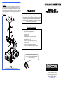
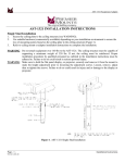
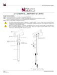
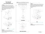
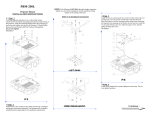
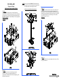
SP-CEIL-003
Projector Mount
INSTALLATION INSTRUCTIONS
q Step 1
Invert the projector and place it on a soft and flat surface.
Locate the four (4) 6 (mm) mounting points found on the bottom
of the projector (C). Align and secure the mounting bracket (B)
using the six (6) 8 (mm) x 10 (mm) Phillip screws (A) (supplied).
Do not over tighten!
See Figure 1
NOTE: If the (Optional) SP-LTMT-EXT Adjustable height
suspension adapter is a part of the installation, securely install
the ceiling adapter to the ceiling at this time.
(Refer to its Installation Instructions)
q Step 3
Install the two (2) conical spacers (J) and two (2) flat washers (K) two
(2) hinge pin screws (L) loosely on both sides of the base box (H).
Raise the projector with the mounting bracket attached and slip though
the hinge pin slots openings on the bracket into the base box. Install the
two (2) angle locking screws (I) adjust the angle, lock it, and then
tighten the hinge pin screws (L).
See Figure 2
q Step 4
Check all the hardware for proper tightness and security. Do not
over tighten hardware.
q Step 2
Install the base box securely to the ceiling structure in
accordance with proper commercial standards. Use
(commercially available) suitable hardware depending on the
installation requirements.
q Step 5
Install the two (2) conical spacers (J) and two (2) flat washers (K) two
(2) hinge pin screws (L) loosely on both sides of the base box (H).
Raise the projector with the mounting bracket attached and slip though
the hinge pin slots openings on the bracket into the base box. Install the
two (2) angle locking screws (I) adjust the angle, lock it, and then
tighten the hinge pin screws (L).
See Figure 3
The ceiling should be capable of supporting a weight of
at least five (5) times the weight of 45 Lbs. If it cannot, the
ceiling must be reinforced. Proper installation procedure
by qualified personnel as outlined in the installation
instructions must be adhered to. Failure to do so could
result in serious personal injury.
DESCRIPTION/HARDWARE
A. 8 (mm) x 10 (mm) Phillip Screws (6ea)
B. SP-CEIL-003 Mounting Bracket (1ea)
C. Projector (Not Supplied)
D. Projector’s Feet
E. Projector Lens
F. Suitable Hardware (Commercially Available)
G. Ceiling Structure (See Warning Label)
H. Base Box/Jam Nut (1ea)
I. 6 (mm) x 12 (mm) Angle Locking Screws (2ea)
J. Conical Spacers (2ea)
K. Flat Washers (2ea)
L. 6 (mm) x 12 (mm) Hinge Pin Screws (2ea)
M. SP-LTMT-EXT Adjustable Suspension Adapter
N. Suspension Adapter Adjustable Pins (2ea)
For further information or ordering assistance
contact us at the phone/address number shown
on the front of this page.
Check all hardware for proper tighten and security.
27700B S.W. Parkway Ave.
Wilsonville, Oregon 97070-9215
Phone 1-800-294-6400 Fax
www.infocus.com