1
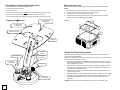
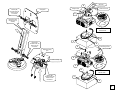
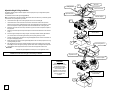
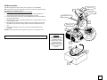
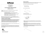
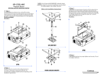
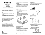
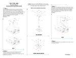
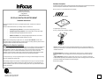
Hardware description The Digital Projector Mount utilizes the following hardware. Note that the letters associated with the hardware on this list correspond to the letters listed in the instructions for each installation method. A. Four (4) 6 (mm) x 10 (mm) Phillips head screws (supplied) 27700B S.W. Parkway Ave. Wilsonville, Oregon 97070-9215 1-800-294-6400 www.infocus.com SP-CEIL-010 DIGITAL PROJECTOR MOUNT B. One (1) mounting bracket (supplied) Installation Instructions These are the installation instructions for your Digital Projector Mount. Included are four methods of installation. Select the method that works best for your viewing situation. The methods are: ° Fixed Height Ceiling Installation— best for short ceilings, eight (8’) or lower ° Adjustable Height Ceiling Installation—best for high ceilings, nine (9’) feet or higher ° SP-LTMT-EXTP-S height adjustable extension is required. ° Wall Mount Installation—for installing the Digital Projector Mount on a rear wall the C. Digital Projector (not included) D. One (1) Litemount Plus® assembly (supplied) SP-LTMT-EXTP-S height adjustable extension is required. NOTE: If the required height range is greater than 12½", the optional SP-LTMT-EXTP could be used to extend the length of the suspension adapter. For further information or ordering assistance, please contact us at the phone number and address listed at the top of this column. Before You Start the Installation The wall or ceiling where you want to install the digital projector must be capable of supporting a weight that is five (5) times the weight of 7lbs the projector you are installing. Consult the projector’s documentation for weight specifications. If the wall, ceiling, tabletop, shelf, or floor is not strong enough to handle five (5) times the weight of 7lbs, then you must reinforce the installation environment. If you are unsure about the installation environment, please consider having it reinforced and having the projector installed by qualified personnel. Failure to do so could result in serious personal injury and damage to the projector. To avoid personal injury, use only an approved projector mount. Using an unauthorized projector mount may lead to poor ventilation and projector failure. When installing the projector mount, keep in mind that the projector’s focus ring is not squarely in the center of the front of the projector, but offset by several inches. Make sure that when you mount the projector you offset the installation to match the amount of inches that the projector’s focus ring is offset from the center of the front of the projector. R NOTE: Hardware item (E) is what secures the Digital Projector Mount to your ceiling, wall, tabletop, floor. Make sure you consult with your local hardware store staff for the type of hardware that works best for your installation environment. E. SINGLE WOOD STUD: If mounting on a single wood stud use three (3) #14 x 2" Lag bolts (minimum) commercially available. Use the mounting points on the center of the plate as indicated in the assembly diagram. ° SOLID STRUCTURE: If mounting to a solid structure use four (4) 5/16" x 2" Lag bolts or commercially available hardware (depending on the installation requirements). Use the mounting points found on the outer points of the mounting plate as indicated in the assembly diagram. F. Allen wrench (supplied) LISTED E176225 Copyright by InFocus Corporation Wilsonville, OR. All rights reserved 1 Tools Needed for Installing the Digital Projector Mount Getting the projector ready You need the following tools to install the Digital Projector Mount: Before you start the installation process, prepare your Digital Projector by performing the following steps (FIGURE 1). • Phillips head screwdriver (not included) • Allen wrench (included) 1. Turn the projector (C) upside down and place it on a clean flat surface, preferably on a towel. • Drill (for installation environment only - do not use a drill on the Digital Projector or the Digital Projector Mount) and drill bit to match the hardware for your installation environment (not included) 2. Locate the mounting bracket (B) and align it over the holes on the projector. 3. Locate the four (4) 6 (mm) x 10 (mm) Phillips head screws (A). 4. Use the Phillips head screwdriver to secure the mounting bracket (B) to the projector via the three • The commercially available hardware (E) that is required by your installation environment (not included) (3) Phillips head screws (A). Do not over-tighten the screws. Lightmount Plus® Overview (3) Single wood stud mounting points FIGURE 1 (4) Solid structure mounting points A B (2) Cable access points C Ceiling plate Adjustable extension (2) Tension knobs Screen side (Yellow indicator) Safety knobs (Red indicator) (Optional) Fixed Height Ceiling Installation Complete the following steps to install the projector mount and projector on your ceiling. This installation works best with low ceilings (FIGURE 2). Note: Look at the bottom of the mount assembly (D) and locate the arrow. Make sure you install the projector mount with the arrow pointing toward your screen. 1. Remove the upper plate from the assembly (D) secure to the ceiling structure using the commercially available hardware (E) suitable for your environment. Be sure that the mount assembly screen indicator arrow is pointing toward your screen. 2. Replace the mount assembly with the upper plate and fully raise the safety knob and tension knobs all the way. Carefully raise the projector (C) with the mounting bracket (B) attached and insert it into the bottom of the mount assembly (D) by its tabs. 3. Rotate the projector (C) with the mounting bracket (B) attached 180º so that the projector’s focus ring is pointing toward your screen. 4. Align the safety knob on the mount assembly (D) with the end of the arrow-shaped slot on the mounting bracket (B) and screw it through the opening to prevent further rotation. Hand-tighten the safety knob. 5. Hand-tighten the remaining two tension knobs to secure the mounting bracket (B) to the mount assembly (D). Clamp plate Lower assembly CAUTION: Check all of the hardware for proper tightness and security. Do not over-tighten the screws. 2 Wood stud E Ceiling structure Center of wood stud Ceiling plate Remove (M8) Hex head screws, flat washers and star lock washers D Remove the center extension from the assembly Insert and rotate 180° and lock down B C Remove (M8) Hex head screws, flat washers and star lock washers A Solid ceiling structure E Replace the ceiling plate D Bottom assembly C B Replace (M8) Hex head screws, flat washers and star lock washers Insert and rotate 180° and lock down C A 3 Wood stud E Ceiling structure Center of wood stud Adjustable Height Ceiling Installation Complete the following steps to install the projector mount and projector on your ceiling with the optional suspension adapter. D Adjustable screws This installation works best with high ceilings (FIGURE 3). Extension adapter Note: Look at the bottom of the upper assembly (D) and locate the arrow. Make sure you install the projector mount with the arrow pointing toward your screen. 6. Use the Allen wrench (F) to remove the upper plate from the mount assembly (D). 7. Use the Allen wrench to remove the two screws from the enclosed end of the of the suspension adapter, and place it into the slotted extension on the upper plate (E). Make sure that the two (2) outer holes on the suspension adapter align with the holes on the slotted extension on the upper plate. 8. Replace the two screws removed in step 2 into the two (2) holes to secure the suspension adapter to the upper plate. 9. Attach the mount assembly to the suspension adapter and secure them with the two screws removed in step 1. 10. Secure the upper assembly to the ceiling using the commercially available hardware (E) suitable for your environment. Be sure that the upper assembly arrow is pointing toward your screen. 11. Carefully raise the projector (C) with the mounting bracket (B) attached and insert it into the bottom of the upper assembly (D) by its tabs. 12. Rotate the projector (C) with the mounting bracket (B) attached 180º so that the projector’s focus ring is pointing toward your screen. 13. Align the safety knob on the mount assembly with the end of the arrow-shaped slot on the mounting bracket (B) and screw it through the opening to prevent further rotation. Hand-tighten the safety knob. 14. Hand-tighten the remaining two tension knobs to secure the mounting bracket to the amount C Insert and rotate 180° and lock down B C A Solid ceiling structure D SEEassembly. FIGURE 3 CAUTION: Check all of the hardware for proper tightness and security. Do not over-tighten the screws. NOTE: Use the Allen wrench key (F) for the following modification E Adjustable screws Extension adapter WARNING C When using the optional extension adapters and making a height adjustment while secured to the wall or ceiling do not remove the screws completely from the extension. Failure to do so could result in injury and damage to the projector. Insert and rotate 180° and lock down B C 4 A Wall Mount Installation Wall wood stud Complete the following steps to install the projector mount and projector to your wall. (FIGURE 4) Note: Look at the bottom of the upper assembly (D) and locate the arrow. Make sure you install the projector mount with the arrow pointing toward your screen. D Wall structure NOTE: Follow step 3 to secure the extension to the mount assembly. 15. Secure the upper plate to the wall using the commercially available hardware (E) suitable for your environment. Be sure that the screen indicator arrow is pointing toward your screen. 16. Carefully raise the projector (C) with the mounting bracket (B) attached and insert it into the bottom of the mount assembly by its tabs. 17. Rotate the projector (C) with the mounting bracket (B) attached 180º so that the projector’s focus rings is pointing toward your screen. 18. Align the safety knob on the mount assembly with the end of the arrow-shaped slot on the mounting bracket (B) and screw it through the opening to prevent further rotation. Hand-tighten the securing knob. 19. Adjustable extension E Adjustable screws Hand-tighten the remaining two tension knobs to secure the mounting bracket (B) to the mount assembly (D). B CAUTION: Check all of the hardware for proper tightness and security. Do not over-tighten the screws. SEE FIGURE 4 NOTE: Use the Allen wrench key (F) for the following modification WARNING When using the optional extension adapters and making a height adjustment while secured to the wall or ceiling do not remove the screws completely from the extension. Failure to do so could result in injury and damage to the projector. C B A C 5