1
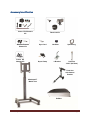
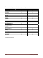
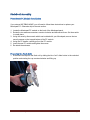
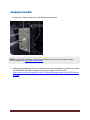
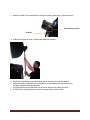
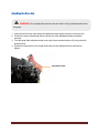
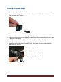
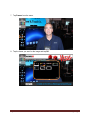
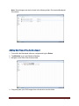
PhotoBooth Setup Guide 009-1420-00 *009-1420-00* IMPORTANT NOTES PhotoBooth is a combination of various manufacturer items, such as the camera and light. Please read all manufacturer documentation BEFORE following these instructions. Pay particular attention to all safety and regulatory information contained therein. InFocus is not liable for damage or injury caused by improperly using these items. Trademark information Apple, Mac and Facetime are trademarks or registered trademarks of Apple, Inc. Microsoft, Windows, PowerPoint, Excel and Word are trademarks or registered trademarks of Microsoft Corporation. The SDXC logo is a trademark of SD-3C, LLC. Canon and Rebel are trademarks or registered trademarks of Canon Inc. D-Lite It and Elinchrom are trademarks or registered trademarks of Elinchrom LTD. Kaiser is a trademark or registered trademark of Kaiser Fototechnik GmbH & Co.KG. Chimera is a trademark or registered trademark of Chimera Lighting. Avenger and Manfrotto are trademarks or registered trademarks of Lino Manfrotto + co. Spa. Lowel is a trademark or registered trademark of Lowel Light Manufacturing. Vello, Freewave, and Impact are trademarks or registered trademarks of Gradus Group LLC. InFocus, In Focus, INFOCUS (stylized) and Mondopad are either registered trademarks or trademarks of InFocus Corporation in the United States and other countries. All other trademarks are the property of their respective owners. Any other trademarks, service marks, personal names or product names are assumed to be the property of their respective owners and are used only for reference. There is no implied sponsorship, affiliation, certification, approval or endorsement if we use one of these terms. Contents IMPORTANT NOTES ............................................................................................................................................ 1 Trademark information ...................................................................................................................................... 1 Contents ............................................................................................................................................................ 2 Accessory Identification ..................................................................................................................................... 3 PhotoBooth Assembly ........................................................................................................................................ 5 PhotoBooth PC Module Installation .......................................................................................................................... 5 Preparing the Flash Unit ............................................................................................................................................ 5 Attaching the Flash Unit ............................................................................................................................................ 8 Attaching the Pivot Arm .......................................................................................................................................... 10 Preparing the Camera ............................................................................................................................................. 11 Preparing the Wireless Trigger ................................................................................................................................ 13 Taking a PhotoBooth Photo ............................................................................................................................... 14 Framing Images ................................................................................................................................................. 15 Adding New Frame Files to Mondopad .............................................................................................................. 18 Accessing additional documentation ................................................................................................................. 20 Troubleshooting ................................................................................................................................................ 21 Accessory Identification Canon® EOS Camera Kit Wireless Remote Shutter Kit Canon® AC Adapter Kit Flash Unit Kit Sync Cord Super Clamp Hot Shoe L-Bracket Speed Ring Half Pole 18-30” (46-74cm) Pivot Arm with Camera Bracket Mondopad™ Mobile Cart Softbox Accessory Identification Page 3 The accessories which you receive depend upon the part number you ordered: INF-5520-PB-C INF-PBKit-NOMP AC Adapter Kit X X Camera Kit X X Flash Unit Kit X X Half Pole X X Hot Shoe X X L-Bracket X X Pivot Arm X X Mondopad** X Mondopad Mobile Cart X Mondopad PC with Photobooth Software installed** X X Remote Shutter Kit X X Softbox X X Speed Ring X X Super Clamp X X Sync Cord X X ** Not shown on previous page. Page 4 Accessory Identification PhotoBooth Assembly PhotoBooth PC Module Installation If you ordered INF-PBKit-NOMP, you will need to follow these instructions to replace your Mondopad PC. Otherwise skip to the next section. 1. Locate the Mondopad PC module on the back of the Mondopad panel. 2. Rotate the two antenna connectors counter-clockwise and disconnect them. Set them aside in a safe place. 3. Using the security allen wrench which was included with your Mondopad, remove the two security screws on the top and bottom of the PC module. 4. Using the PC handle, carefully pull out the PC module. 5. Insert the new PC module and tighten the screws. 6. Re-attach the antennas. Preparing the Flash Unit 1. Disconnect the cap from the flash unit by sliding the blue “lock” slider button to the unlocked position and rotating the cap counterclockwise and lifting up. PhotoBooth Assembly Page 5 2. Attach the speed ring to the flash unit by aligning the slots of the speed ring to the front of the flash unit and turning clockwise until it is fully attached. Move the blue “lock” slider button to the locked position. 3. Route the cables into each corner of the softbox. Page 6 PhotoBooth Assembly 4. Insert the cable ends into the speed ring. 5. Secure the Velcro at each corner of the softbox to complete its rectangle shape. PhotoBooth Assembly Page 7 Attaching the Flash Unit 1. Attach the L-bracket to the back of the Mondopad mobile cart. NOTE: If your mobile cart does not have holes drilled into it as per below, please contact InFocus Support at: www.infocus.com/support. 2. Attach the Mondopad panel to the mobile cart as per the manufacturer’s instructions and the INF-MOBCART addendum located on the InFocus Support site (Direct link: https://portal.infocus.com/support/Product%20Pages/downloads.aspx?mic=INF5520&on=do wnloads). Page 8 PhotoBooth Assembly 3. Attach the flash unit to the half pole using the knurled clamp screw. Tighten securely. Knurled Clamp Screw Tilt Head 4. Slide the half pole onto the L-bracket and adjust as needed. 5. Adjust the half pole above the Mondopad panel, allowing room for the camera. 6. Adjust the angle of the flash unit and softbox to accommodate the camera and your situation, using the flash unit tilt head. 7. Plug the power cord into the flash unit and route through the mobile cart post. 8. Plug the other end of the power cord into a power strip or power outlet. PhotoBooth Assembly Page 9 Attaching the Pivot Arm WARNING: Do not attach the camera to the arm until it is fully positioned and locked into place. 1. Insert the stud into the super clamp and attach the super clamp securely to the pivot arm. 2. Position the super clamp along the top vertical bar of the Mondopad frame and tighten securely. 3. Turn the large black adjustment knob on the pivot arm counterclockwise. All pivot points will become loose. 4. Position the arm similar to the image below and turn the adjustment knob clockwise to tighten. Adjustment Knob Page 10 PhotoBooth Assembly Preparing the Camera Note: For this section, you will need the Canon AC adapter kit, the Canon camera, camera lens and an SD card (required). Mode Dial Power Switch Lens Focus Mode Switch SD Slot Battery Door 1. Insert a SD card (not included) into the camera’s SD slot on the right-hand side of the camera, being careful to align the SD card appropriately. 2. Attach the lens, by aligning the dots and turning the lens clockwise until an audible click is heard. 3. Set the Lens Focus Mode Switch located on the lens to AF. 4. Using the Canon adapter kit, plug the AC adapter into the DC coupler. AC Power Cord AC Adapter DC Coupler 5. Open the battery door located on the bottom of the camera and insert the DC coupler into the battery slot. 6. Close the battery door, being careful to route the AC adapter cable through the slot in the door. PhotoBooth Assembly Page 11 7. Attach the camera to the pivot arm securely. 8. Carefully loosen the pivot arm adjustment knob to make final adjustments to the camera’s position, being very careful of the camera. WARNING: Turning the adjustment knob will release the arm pivot points. Damage to the camera could occur, if the camera is allowed to fall. 9. Connect the AC adapter to the AC power cord. 10. Plug the other end of the AC power cord to a power strip or power outlet. Page 12 PhotoBooth Assembly Preparing the Wireless Trigger 1. Slide the battery door off. 2. Insert a 12V battery into the wireless receiver, being careful of the battery orientation, and slide the battery door back on. 3. Slide the wireless receiver onto the bottom of the hot shoe. 4. Slide the hot shoe to the camera. Note: The receiver can also be attached using Velcro tape to the back of Mondopad. 5. Attach the sync cable from the sync socket on the back of the flash unit to the hot shoe. Note: Secure excess cable to avoid tripping hazard. 6. Attach the receiver cable to the Remote Control Terminal on the camera and attach the other end to the receiver. Hot Shoe & Receiver Sync Cable (to Flash Unit) Receiver Cable (to Receiver) PhotoBooth Assembly Page 13 Taking a PhotoBooth Photo Cell Button Power Switch 1. 2. 3. 4. Turn Mondopad ON. Turn the camera’s power switch to ON and the Mode Dial to M (“Manual”). Turn the flash unit’s power switch to the ON position. Verify that the Cell button LED is off. If the Cell button LED is lit, press the Cell button to turn it off. 5. Press the receiver’s power button and slide the slider from Hold to Ready. 6. Slide the wireless transmitter button to Single/Bulb. 7. When ready, click the transmitter button. The image will be saved on the SD card and in the View & Share > PhotoBooth folder. Page 14 PhotoBooth Assembly Framing Images 1. From the Mondopad home page, navigate to View & Share. 2. Open an image file. Note: Images created with PhotoBooth appear in the PhotoBooth folder. 3. Tap Annotations. Framing Images Page 15 7. Tap Frames from the menu. 8. Tap the frame you want for the image and tap OK. Page 16 Framing Images 9. To save the image, tap Save JPG. 10. Type a name in the File Name field and tap Save. 11. Saved images can be viewed in the View and Share folder. Framing Images Page 17 Note: Saved images can also be found in the following folder: Documents>Mondopad Documents. Adding New Frame Files to Mondopad 1. From within the Mondopad software, navigate and login to Extras. 2. Tap Minimize to go to the Windows Desktop. 3. Navigate to the Zoos>Files>Frames folder. 4. Copy and paste your PNG images from a thumb drive into this folder. Page 18 Framing Images Note: For best results, PNG images should be the same resolution as the Mondopad (1920 x 1080) and have transparent centers. Framing Images Page 19 Accessing additional documentation To complete the setup of this product and the Mondopad Collaboration software, please download the Installer’s Guide located at www.infocus.com/INF5520docs. Page 20 Accessing additional documentation Troubleshooting The following table is meant to assist you with troubleshooting your PhotoBooth. It is not a comprehensive list. For the best troubleshooting advice, we recommend reviewing the manufacturer’s documentation associated with each part. The flash unit is not turning on The flash unit is at the wrong angle The wireless transmitter is not triggering the flash unit to flash The PhotoBooth images are not being saved in the View & Share>PhotoBooth folder. Troubleshooting Verify that the modeling lamp mode is not set to OFF. Verify that the power switch on the back of the light is turned on. Verify that the power cord is properly connected. Unplug the light and check the main fuse (standard type 5 x 20mm, use only tempered fuse 8 AT (p/n 19022) on the back of the light located near the power cord. If needed, replace the fuse using the spare fuse in the handle. See manufacturer’s documentation for fuse replacement instructions. Unplug the light and check the modeling lamp fuse (fast type 5x20mm, 2.5AF (p/n 19035)). See manufacturer’s documentation for fuse replacement instructions. Check the flash tube. Check the modeling lamp (Modeling lamp 110V 100W (p/n 23006)). Verify that the power outlet is good. An error code is displayed on the D-Lite LCD screen. Refer to the manufacturer’s instructions. Use the tilt head to adjust the angle of the Flash Unit. Verify that the transmitter is on (the LED will be on). Check to see if the receiver is connected properly to the camera. If the transmitter or receiver’s Status LED is off or displaying a dim light, replace the battery. Follow manufacturer instructions. Verify that both the transmitter and receiver have good batteries which are properly installed and in the correct orientation. Decrease your distance between the transmitter and receiver. Extend the antenna on the transmitter. Verify that the camera’s lens cap has been removed. Page 21 The camera turned off. The camera LCD monitor is displaying an error message. Verify that the camera power switch is turned on. Turn the camera off and on again. Verify that the camera’s SD memory card is not full. Verify that the camera’s SD memory card is properly installed and that the card cover is closed. Verify that the SD memory card writeprotect switch is set to the upward position to enable writing and erasing. Verify the AC adapter is properly connected. If using the camera’s battery pack, verify that the battery is fully charged and in the correct orientation. Verify that the battery cover is closed. Verify that the power outlet is good. If the camera’s LCD monitor displays an error, refer to the camera manufacturer’s reference guide. Press the Disp. Button on the camera. (Note: The camera will turn off after 30 minutes of inactivity unless this feature is deactivated. See the camera manufacturer’s reference guide for more information. Refer to the camera manufacturer’s reference guide. For additional troubleshooting support, please refer to the original manufacturer’s documentation or contact: InFocus Corporation Technical Support 6am-5pm PST 877-388-8385 www.infocus.com/support Page 22 Troubleshooting