1
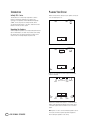
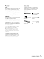
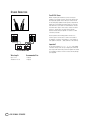
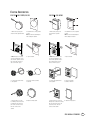
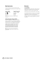
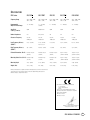
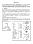
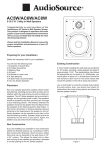
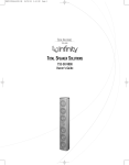
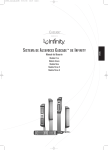
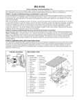
™
TOTAL SPEAKER SOLUTIONS
ERS 110II
ERS 110DT
ERS 210II
ERS 310
ERS HV250
Owner’s Guide
INTRODUCTION
PLANNING YOUR SYSTEM
Infinity ERS™ Series
Before deciding where to best place your speakers, survey your
room and study Figures 1–3.
The ERS Series of in-wall/ceiling loudspeakers continues
Infinity’s longstanding commitment to accurate sound
reproduction. Our patented Ceramic Metal Matrix Diaphragm
(CMMD™) drivers and precision dividing networks deliver
uncompromised performance in any stereo, multichannel home
theater or whole-house music system.
Right
Front
Channel
Left
Front
Channel
Infinity Subwoofer
(optional)
Unpacking the Speakers
Carefully unpack the speakers. If you suspect damage from transit,
report it immediately to your dealer and/or delivery service. Keep
the shipping carton and packing materials for future use. All
models include a mounting template and paint shield.
Couch
Figure 1.
Right Infinity Subwoofer
(optional)
Front
Channel
Left
Front
Channel
Center
Channel
Couch
Left
Surround
Channel
Right
Surround
Channel
Figure 2. This overhead view shows a typical home theater
system arrangement.
Left
Front
Channel
Center
Channel
(above or below TV)
Right
Front
Subwoofer
Channel
Couch
Left
Surround
Channel
Left
Rear
Channel
Center
Rear
Channel
Right
Rear
Channel
Right
Surround
Channel
Figure 3.This overhead view shows a 6- or 7-channel home
theater system arrangement. Left/right rear channels are for
a 7-channel system. Center rear channel is for a 6-channel
system.
2
ERS IN-WALL SPEAKERS
Note: Figures 1, 2 and 3 show recommended speaker locations.
You may also follow these general placement suggestions
when installing the speakers in the ceiling.
PLACEMENT
INSTALLATION
Stereo
The ERS Series in-wall speakers were designed to be easily
installed. However, if you are unsure of your ability to properly
install these loudspeakers, please contact your dealer or a
qualified installer.
Before deciding where to place your ERS Series speakers, survey
your room and think about placement, keeping the following
points in mind, and using Figure 1, on previous page, as a guide:
• For best results, place the speakers 6'–8' apart.
• When installing in the wall, position each speaker so that the
tweeter is as close to ear level as practical.
• Refer to “Home Theater” below if you also plan to use the
speakers in a home theater system.
Tools Needed
Pencil
Phillips #2 screwdriver
Measuring tape
Utility knife
Carpenter’s level
Awl
Home Theater
For front-channel use, place one speaker on the left and another
on the right along either side of the television.
A center channel speaker should go directly above or below the
television and can be an in-wall or freestanding center channel.
For left and right surround channels, place one speaker on the
left and another on the right, to the side of or slightly behind the
listening area.The surround speakers should be mounted at a
height of between 4 feet and 7 feet.
In 6- or 7-channel configurations, place the rear channel(s)
behind the listening position, as shown in Figure 3.
Note: An Infinity powered subwoofer will add impact and
realism to both music and film soundtracks. Contact your
Infinity dealer for recommendations on subwoofer models for
your application.
Proper placement of the speakers is an important step
in obtaining the most realistic soundstage possible.These
recommendations are for the optimal placement of the loudspeakers. Use these placement recommendations as a guide.
Slight variations will not diminish your listening pleasure.
ERS IN-WALL SPEAKERS
3
SPEAKER CONNECTIONS
Turn Off All Power
Before completing the installation, you must connect your
speakers to your system. First, turn off all audio-system power.
Use high-quality speaker wire to make your connections. Use
at least #16-gauge speaker wire with polarity coding. Heavier
gauge wire is recommended for larger distances. Consult the
chart below left or your dealer for recommendations.The side
of the wire with a ridge or other coding is usually considered
positive (+) polarity. Also, consult the owner’s manuals
that were included with your amplifier or receiver to confirm
connection procedures.
Figure 4.
Observe polarities when making speaker connections, as
shown in Figure 4. Connect each + terminal on the back of
the amplifier or receiver to the respective + (red) terminal on
each speaker. Connect the – (black) terminals in the same way.
Important!
Do not reverse polarities (i.e., + to – , or – to +) when making
connections. Doing so will cause poor imaging and diminished
bass response. Be certain that positive and negative wire strands
are completely isolated to avoid short circuits that may damage
your equipment.
4
Wire Length
Recommended Size
Up to 100 ft.
Greater than 100 ft.
16-gauge
12-gauge
ERS IN-WALL SPEAKERS
EXISTING CONSTRUCTION
ERS 110II, ERS 110DT, ERS 310
ERS 210II, ERS HV250
1. Remove the plastic paint
shield from the speaker frame.
1. Remove the plastic paint
shield from the speaker
frame.
2. Determine the correct speaker
location.
Note: Use the included template
when cutting the drywall.
2. Determine the correct speaker
location.
Note: Use the included template
when cutting the drywall.
≥1/2"
≥1/2"
≥1/2"
≥1/2"
≥1/2"
≥1/2"
3. Note: Always allow at least
one-half inch between a wall
stud and the speaker cutout or
the locking tabs will not be
able to swivel into place.
4. Cut the drywall.
3. Note: Always allow at least
one-half inch between a wall
stud and the speaker cutout or
the locking tabs will not be
able to swivel into place.
4. Cut the drywall.
5. Connect the speaker wires
to the speaker.
6. Place the frame assembly
in the wall.
5. Connect the speaker wires
to the speaker.
6. Place the speaker
assembly in the wall.
7. Screw down each of the
four Phillips head screws.The
locking tabs will swivel into
place and secure the unit to
the rear surface of the
drywall.
8. Attach the metal grille.
7. Screw down each of the six
Phillips head screws.The locking
tabs will swivel into place and
secure the unit to the rear
surface of the drywall.
8. Attach the metal grille.
ERS IN-WALL SPEAKERS
5
NEW CONSTRUCTION
OPERATION
If you wish to preinstall a rough-in frame before the drywall
is installed, you will need to purchase the correct rough-in-frame
kit for your model:
Surround Modes
Speaker Model
Rough-In-Frame Kit
ERS 110II, ERS 110DT
ERS 210II
ERS 310
ERS HV250
ERS 110RIF or IW6R RIF
ERS 210RIF
IW8R RIF
IW55 RIF
Detailed installation instructions are supplied with the
rough-in kit.
Painting the Speaker Frame and Grille
ERS Series loudspeakers can be painted to match any décor.
If you wish to change their color, the satin finish on the grille
and frame will function as a primer coat. Before painting, install
the paint shield (inner section of template in the assembly kit)
securely into the recess in the baffle.This will protect the
speaker components and baffle from paint residue. Use a
high-quality spray paint, and apply a thin coat of color.
Be certain the grille perforations remain free of paint.
Filling them with paint will diminish the sound quality.
Note: Gently remove the acoustical foam blanket from
the grille before painting. Reattach the blanket after the
paint has dried.
6
ERS IN-WALL SPEAKERS
When using the system in a Dolby* Digital or DTS® home theater
system, make sure all speakers are set to “Small.” When using
the ERS Series in a Dolby Pro Logic* home theater system,
make sure the receiver’s center channel mode is set to “Normal.”
Some Dolby Digital-equipped receivers/processors offer different
setup options for each source or surround mode: e.g., CD-stereo,
videotape, Dolby or Pro Logic. In each case, follow your
equipment’s instructions to ensure that the subwoofer (if you have
one) output is turned on and that the speakers are set to “Small”
in each mode.
SPECIFICATIONS
ERS Series
ERS 110II
ERS 110DT
ERS 310
ERS 210II
ERS HV250
Frequency Range
47Hz – 22kHz (±3dB)
35Hz (–10dB)
47Hz – 22kHz (±3dB)
35Hz (–10dB)
45Hz – 22kHz (±3dB)
29Hz (–10dB)
47Hz – 22kHz (±3dB)
35Hz (–10dB)
45Hz – 22kHz (±3dB)
38Hz (–10dB)
Recommended
Amplifier Power Range
10 – 125 Watts
10 – 130 Watts
(65 WPC)
10 – 135 Watts
10 – 125 Watts
10 – 125 Watts
Sensitivity
(2.83V @ 1 meter)
89dB
88dB/Channel
89dB
89dB
89dB
Nominal Impedance
8Ω
8 Ω /Channel
8Ω
8Ω
8Ω
Crossover Frequency
2,300Hz;
24dB/Octave
2,400Hz;
12dB/Octave
2,300Hz;
12dB/Octave
2,300Hz;
24dB/Octave
2,600Hz;
12dB/Octave
Low-Frequency Driver(s)
(CMMD™)
6-1/2" (165mm)
6-1/2" (165mm)
Dual voice coil
8" (200mm)
6-1/2" (165mm)
Dual 5" (130mm)
High-Frequency Driver(s)
(CMMD™)
3/4" (19mm)
Dual 3/4" (19mm)
1" (25mm)
3/4" (19mm)
3/4" (19mm)
External Dimensions (W x H)
Diameter: 9-3/16"
(233mm)
Diameter: 9-3/16"
(233mm)
Diameter: 10-7/8"
(276mm)
8-3/4" x 12-3/4"
(222mm x 324mm)
15-3/8" x 7-1/2"
(391mm x 191mm)
Mounting Cutout Size (W x H)
Diameter: 7-7/8"
(200mm)
Diameter: 7-7/8"
(200mm)
Diameter: 9-1/2"
(241mm)
7-5/8" x 11-3/8"
(194mm x 289mm)
13-7/8" x 6-3/16"
(352mm x 157mm)
Mounting Depth
3-1/2" (89mm)
3-1/2" (89mm)
4-1/4" (108mm)
3-1/4" (83mm)
3-7/8" (98mm)
Weight (Net)
3.1 lb (1.4kg)
4 lb (1.8kg)
5.6 lb (2.5kg)
3.5 lb (1.6kg)
5.7 lb (2.6kg)
Infinity continually strives to update and improve existing products, as well as create new ones.
The specifications and construction details in this and related Infinity publications are
therefore subject to change without notice.
Declaration of Conformity
We, Harman Consumer Group International
2, route de Tours
72500 Chateau-du-Loir
France
declare in own responsibility that the products
described in this owner’s manual are in compliance
with technical standards:
EN 61000-6-3:2001
EN 61000-6-1:2001
Laurent Rault
Harman Consumer Group International
Chateau-du-Loir, France 1/05
ERS IN-WALL SPEAKERS
7
© 2005 Harman International Industries, Incorporated
Infinity Systems, 250 Crossways Park Drive, Woodbury, NY 11797 USA 516.674.4INF (USA only) www.infinitysystems.com
* Trademarks of Dolby Laboratories. DTS is a registered trademark of Digital Theater Systems, Inc.
Infinity is a registered trademark, and ERS and CMMD (patent nos. 6,327,372 and 6,404,897) are trademarks, of Harman International Industries, Incorporated. Part No. 406-000-05203 1/05