1
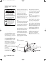
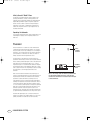
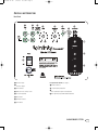
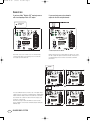
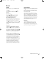
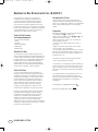
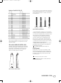
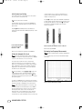
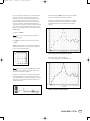
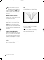
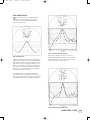
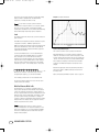
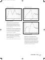
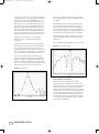
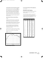
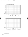
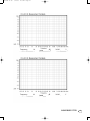
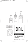
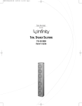
Cascade 15 OM
9/14/05
2:35 PM
Page 1
C ASCADE
™
Compact Powered Subwoofer
CASCADE MODEL FIFTEEN
™
Owner’s Guide
(120V)
Cascade 15 OM
9/14/05
2:35 PM
Page 2
IMPORTANT SAFETY PRECAUTIONS
Read First!
CAUTION
RISK OF ELECTRIC SHOCK
DO NOT OPEN
CAUTION: To reduce the risk of electric shock,
do not remove cover (or back).
No user-serviceable parts inside.
Refer servicing to qualified service personnel.
CAUTION: To prevent electric shock,
do not use this (polarized) plug with
an extension cord, receptacle or other outlet
unless the blades can be fully inserted to
prevent blade exposure.
The lightning flash with arrowhead symbol,
within an equilateral triangle, is intended to
alert the user to the presence of uninsulated
“dangerous voltage” within the product’s
enclosure that may be of sufficient magnitude to constitute
a risk of electric shock to persons.
The exclamation point within an equilateral
triangle is intended to alert the user to the
presence of important operating and
maintenance (servicing) instructions in the
literature accompanying the appliance.
1. Read these instructions.
2. Keep these instructions.
3. Heed all warnings.
4. Follow all instructions.
5. Do not use this apparatus near water.
6. Clean only with a dry cloth.
7. Do not block any ventilation openings. Install in
accordance with the manufacturer’s instructions.
8. Do not install near any heat sources such as
radiators, heat registers, stoves or other apparatus
(including amplifiers) that produce heat.
9. Do not defeat the safety purpose of the
polarized or grounding-type plug. A polarized plug
has two blades with one wider than the other. A
grounding-type plug has two blades and a third
grounding prong.The wide blade or the third
prong are provided for your safety. If the provided
plug does not fit into your outlet, consult an
electrician for replacement of the obsolete outlet.
10. Protect the power cord from being walked on
or pinched, particularly at plugs, convenience
receptacles and the point where they exit from the
apparatus.
11. Only use attachments/accessories specified by
the manufacturer.
12. Use only with the cart, stand,
tripod, bracket or table specified
by the manufacturer or sold with
the apparatus. When a cart is
ii
CASCADE MODEL FIFTEEN
used, use caution when moving the cart/apparatus
combination to avoid injury from tip-over.
13. Unplug this apparatus during lightning storms
or when unused for long periods of time.
14. Refer all servicing to qualified service
personnel. Servicing is required when the
apparatus has been damaged in any way, such
as power-supply cord or plug is damaged, liquid
has been spilled or objects have fallen into the
apparatus, the apparatus has been exposed to rain
or moisture, does not operate normally, or has
been dropped.
15. Do not use attachments not recommended by
the product manufacturer, as they may cause
hazards.
16. This product should be operated only from the
type of power source indicated on the marking
label. If you are not sure of the type of power
supply to your home, consult your product dealer
or local power company. For products intended to
operate from battery power, or other sources,
refer to the operating instructions.
17. If an outside antenna or cable system is
connected to the product, be sure the antenna or
cable system is grounded so as to provide some
protection against voltage surges and built-up
static charges. Article 810 of the National
Electrical Code, ANSI/NFPA 70, provides
information with regard to proper grounding of
the mast and supporting structure, grounding of
the lead-in wire to an antenna discharge unit, size
of grounding conductors, location of antenna
discharge unit, connection to grounding
electrodes, and requirements for the grounding
electrode. See Figure A.
Figure A.
Example of Antenna Grounding as per
National Electrical Code ANSI/NFPA 70
18. An outside antenna system should not be
located in the vicinity of overhead power lines
or other electric light or power circuits, or where
it can fall into such power lines or circuits. When
installing an outside antenna system, extreme
care should be taken to keep from touching such
power lines or circuits, as contact with them
might be fatal.
19. Do not overload wall outlets, extension cords,
or integral convenience receptacles, as this can
result in a risk of fire or electric shock.
20. Never push objects of any kind into this
product through openings, as they may touch
dangerous voltage points or short-out parts that
could result in a fire or electric shock. Never
spill liquid of any kind on the product.
21. Do not attempt to service this product
yourself, as opening or removing covers may
expose you to dangerous voltage or other hazards.
Refer all servicing to qualified service personnel.
22. When replacement parts are required, be sure
the service technician has used replacement
parts specified by the manufacturer or that have
the same characteristics as the original part.
Unauthorized substitutions may result in fire,
electric shock or other hazards.
23. Upon completion of any service or repairs
to this product, ask the service technician to
perform safety checks to determine that the
product is in proper operating condition.
24. The product should be mounted to a wall or
ceiling only as recommended by the manufacturer.
Cascade 15 OM
9/14/05
2:35 PM
Page 3
CASCADE MODEL FIFTEEN OWNER’S GUIDE
Table of Contents
ii
Important Safety Precautions
1
Unpacking the Subwoofer
1
Placement
2
Controls and Connections
3
Connections
4
Operation
5
Room Adaptive Bass Optimization System™ (R.A.B.O.S.™)
6
Contents of the R.A.B.O.S.Test CD
6
The R.A.B.O.S. Sound-Level Meter (RSLM)
6
RSLM Placement
7
Initial System-Level Setting
7
Setting the Subwoofer Test Level
7
Performing Low-Frequency Measurements
9
What Does a Parametric Equalizer Do?
9
Completing the Measurement Template
10
Using the Width Selector
11
Level
11
What You Measure, What to Do
14
Adjusting the R.A.B.O.S. Equalizer
15
Final System Balance
16
Maintenance and Service
17
R.A.B.O.S. Measurement Templates
19
Specifications
CASCADE MODEL FIFTEEN
iii
Cascade 15 OM
9/14/05
2:35 PM
Page 4
Infinity Cascade™ Model Fifteen
The Infinity Cascade Model Fifteen continues Infinity’s longstanding commitment to accurate sound reproduction. Our
advanced drivers, high-powered amplifier and proprietary Room
Adaptive Bass Optimization System,™ along with a rigid, wellbraced enclosure, combine to deliver uncompromising bass
performance in any stereo or multichannel home theater. In
addition, the slim profile allows for easy integration into any
residential environment.
Unpacking the Subwoofer
If you suspect damage from transit, report it immediately to your
dealer. Keep the shipping carton and packing materials for
future use.
PLACEMENT
Since the installation of a subwoofer can be somewhat more
complicated than installing full-range speakers, it is essential
that you read this section very carefully prior to connecting the
subwoofer to your system. Should you have questions relating to
your installation, it is advisable to call either your dealer or
Infinity’s Customer Service Department for advice.
The performance of the subwoofer is directly related to its
placement in the listening room and how you align the subwoofer
with its satellite speakers. Setting the volume of the subwoofer in
relationship to the left and right speakers is also of critical
importance because it is essential that the subwoofer integrate
smoothly with the entire system. Setting the subwoofer’s volume
level too high will result in an overpowering, boomy bass. Setting
the volume level too low will negate the benefits of the
subwoofer.
Here are several additional installation facts that may prove
useful. It is generally believed by most audio authorities that low
frequencies (below 125Hz) are nondirectional and, therefore,
placement of a subwoofer within any listening room is not
critical. While in theory it is true that the larger wavelengths of
extremely low frequencies are basically nondirectional, the fact
is that, when installing a subwoofer within the limited confines
of a room, reflections, standing waves and absorptions generated
within the room will strongly influence the performance of any
subwoofer system. As a result, the specific location of the
subwoofer becomes important, and we strongly recommend that
you experiment with placement before choosing a final location.
Placement will depend upon your room and the amount and
quality of bass required (for example, whether or not your room
permits placement of the subwoofer near either satellite).
1
CASCADE MODEL FIFTEEN
SUB
RIGHTCHANNEL
SPEAKER
PRIMARY
LISTENING
AREA
Figure 1.This example shows the subwoofer positioned behind
the right-channel satellite speaker to re-create the actual
location of bass instruments in an orchestra and/or add impact
to movie soundtracks.
Cascade 15 OM
9/14/05
2:35 PM
Page 5
CONTROLS AND CONNECTIONS
Rear Panel
¡
™
£
¢
∞
ª
§
¶
‚
⁄
•
B
¡ Line-Level Inputs
Bass Optimization Controls (see page 5)
™ Line-Level Outputs
ª R.A.B.O.S. Selector
£ Power Indicator
‚ Center-Frequency Adjustment
¢ Subwoofer Level (Volume) Control
⁄ Bass Optimization System Level Adjustment
∞ Crossover Adjustment
B Bass Optimization System Bandwidth Adjustment
§ Phase Switch
¶ Normal/LFE Selector
• Power Switch
CASCADE MODEL FIFTEEN
2
Cascade 15 OM
9/14/05
2:35 PM
Page 6
CONNECTIONS
If you have a Dolby® Digital or DTS® receiver/processor
with a low-frequency-effects (LFE) output:
If your receiver/processor has subwoofer
outputs for the left and right channels:
SUBWOOFER OR
LFE OUTPUT
• Set Normal/LFE Switch to LFE.
• Set Normal/LFE Switch to Normal.
NOTE: In this case, you do not need to use a Y-connector. Simply
connect the LFE output on your receiver/processor to either the
left or right input on the subwoofer.
NOTE: Some receivers have a single subwoofer output (do not confuse
this with a single LFE output as described to the left). In that case, it is
recommended that you use a Y-connector (not included) to maximize
performance.
SUBWOOFER OR
LFE OUTPUT
OR
The Cascade Model Fifteen also includes a set of line outputs.These
outputs allow you to “daisy-chain” one Model Fifteen to multiple Model
Fifteen subwoofers. Simply connect the first subwoofer as described
above and then run a subwoofer cable from the line output(s) to the
line input(s) on the next sub.
NOTE: This line output is before the R.A.B.O.S. circuit. Each subwoofer’s R.A.B.O.S. controls must be individually adjusted during the
R.A.B.O.S. setup.
3
CASCADE MODEL FIFTEEN
Cascade 15 OM
9/14/05
2:35 PM
Page 7
OPERATION
Power On
Crossover Adjustments
Plug your subwoofer’s AC cord into a wall outlet. Do not use the
outlets on the back of the receiver.
Initially set the Subwoofer Level (Volume) Control ¢ to the
“min” position.
Turn on your sub by pressing the Power Switch • on the
rear panel.
NOTE: This control will have no effect if the Normal/LFE Selector
Switch ¶ is set to “LFE.” If you have a Dolby Digital or DTS
processor/receiver, the Crossover Frequency is set by the
processor/receiver. Consult your owner’s manual to learn how
to view or change this setting.
Auto On/Standby
With the Power Switch • in the ON position, the Power
Indicator LED £ will remain backlit in red or green to
indicate the On/Standby mode of the subwoofer.
RED = STANDBY (No signal detected, Amp Off)
GREEN = ON (Signal detected, Amp On)
The subwoofer will automatically enter the Standby mode after
approximately 10 minutes when no signal is detected from your
system.The subwoofer will then power ON instantly when a
signal is detected. During periods of normal use, the Power
Switch • can be left on.You may turn off the Power Switch •
for extended periods of nonoperation, e.g., when you are away
on vacation.
Adjust Level
The Crossover Adjustment Control ∞ determines the highest
frequency at which the subwoofer reproduces sounds. If your main
speakers can comfortably reproduce some low-frequency sounds,
set this control to a lower frequency setting, between 50Hz
and 100Hz.This will concentrate the subwoofer’s efforts on the
ultradeep bass sounds required by today’s films and music. If you
are using smaller bookshelf speakers that do not extend to the
lower bass frequencies, set the Crossover Adjustment Control to
a higher setting, between 120Hz and 150Hz.
Phase Control
The Phase Switch § determines whether the subwoofer
speaker’s pistonlike action moves in and out with the main
speakers (0˚) or opposite the main speakers (180˚). Proper
phase adjustment depends on several variables such as room
size, subwoofer placement and listener position. Adjust the Phase
Switch to maximize bass output at the listening position.
Turn on your entire audio system and start a CD or movie
soundtrack at a moderate level.Turn up the Subwoofer Level
(Volume) Control ¢ about halfway. If no sound emanates from
the subwoofer, check the AC-line cord and input cables. Are the
connectors on the cables making proper contact? Is the AC
plug connected to a “live” receptacle? Has the Power Switch •
been pressed to the ON position? Once you have confirmed that
the subwoofer is active, proceed by playing a CD, record or
cassette. Use a selection that has ample bass information.
Set the overall volume control of the preamplifier or stereo to a
comfortable level. Adjust the Subwoofer Level (Volume) Control ¢
until you obtain a pleasing blend of bass. Bass response should
not overpower the room but rather be adjusted so there is a
harmonious blend across the entire musical range. Many users
have a tendency to set the subwoofer volume too loud,
adhering to the belief that a subwoofer is there to produce lots
of bass.This is not entirely true. A subwoofer is there to enhance
bass, extending the response of the entire system so the bass
can be felt as well as heard. However, overall balance must
be maintained or the music will not sound natural. An
experienced listener will set the volume of the subwoofer so
its impact on bass response is always there but never obtrusive.
CASCADE MODEL FIFTEEN
4
Cascade 15 OM
9/14/05
2:35 PM
Page 8
ROOM ADAPTIVE BASS OPTIMIZATION SYSTEM™ (R.A.B.O.S.™)
Infinity’s R.A.B.O.S. is a simple-to-use, yet sophisticated,
low-frequency calibration system. It is designed to work in
conjunction with the Cascade Model Fifteen self-amplified
subwoofer.The subwoofer contains a parametric equalizer
that you will adjust as indicated by the R.A.B.O.S. test results.
Following these instructions, you will optimize the Cascade Model
Fifteen’s response characteristics to complement its environment.
This will dramatically improve the sound of your system.The
optimization process takes less than 30 minutes.
The R.A.B.O.S. Kit Includes
the Following Components:
• Specialized Sound-Level Meter
• Test CD
• Instructions
• Measurement Templates
• Width Selector
• Adjustment “Key”
What R.A.B.O.S. Does
The Test CD provides specially designed signals you will use
while performing measurements.The Sound-Level Meter provided
is used to “acquire” the information needed for adjustments.You
will create a response plot on the Measurement Template. Using
the Width Selector, you will then determine the appropriate
equalizer settings.The “Key” is used to adjust the parametric
equalizer built into the Cascade Model Fifteen. After adjustment,
the test sequence is repeated to confirm your settings.
The R.A.B.O.S. Goal
It is a fact of audio that what we hear at low frequencies is
determined as much or more by the listening room than by the
loudspeaker itself. Placement of the loudspeakers and listeners
and the acoustical characteristics of the room surfaces are all
important determinants of bass quantity and quality. In most
practical situations, there is little that can be done about this,
except for patient trial-and-error repositioning of the loudspeakers and listeners. Usually, the practical constraints of
a living space and the impracticality of massive acoustical
treatment mean that equalization is the only practical solution.
Professional sound engineers routinely employ sophisticated
measurement systems and equalizers to optimize speakers to
the installation.This has never been practical for the home
audiophile.This is why R.A.B.O.S. was created. R.A.B.O.S.
enables you to identify the dominant low-frequency response
characteristic of your room. Once you know the problem,
R.A.B.O.S. provides the tools needed to optimize the low-frequency
characteristics of the speakers to the room they are in, exactly as
the professional sound engineers do it.
5
CASCADE MODEL FIFTEEN
Performing R.A.B.O.S.Tests
These instructions assume you have already installed your
subwoofer according to the information provided in the Owner’s
Guide. It is also assumed that all equipment in your entertainment
system is interconnected properly and is in good operating
condition.
Preparations
Before beginning R.A.B.O.S. tests, please check the following:
• Set R.A.B.O.S. Switch ª to the ON position.
• Make sure all three R.A.B.O.S. controls, ‚, ⁄ and B, on the
subwoofer are turned fully clockwise.
• Make sure the loudness contour (if any) on your receiver/
processor/preamp is turned off.
• Set the tone controls (Bass and Treble) to their center or
flat positions.
• Bypass all surround and effects features of your receiver/
processor/preamp or set to “Stereo Bypass.”
• If you are using a multichannel surround processor or receiver,
make sure all bass-management features are properly set.The
Audio channels should all be set to “Small” or “High-Pass,” and
the subwoofer set to “On.”
You must have a CD player in the system. A CD player remote
control is quite convenient but not essential.
For best results, it is recommended that all major furnishings are
in place and that all doors and windows in the listening area are
in their normal positions.That is, if you normally listen to music
with all doors closed, then this is how they should be during this
procedure.
Try to minimize ambient noise while running tests.Turn off all
major appliances and any air conditioning or furnace fans.
These can create significant subsonic noise that may be barely
perceptible but which can wreak havoc on low-frequency
measurements.
Critical information is highlighted with this mark:
Helpful hints are marked with this symbol:
Cascade 15 OM
9/14/05
2:35 PM
Page 9
Contents of the R.A.B.O.S.Test CD
Track
1
2
3
4
5
6
7
8
9
10
11
12
13
14
15
16
17
18
19
20
21
22
23
24
25
26
27
28
29
30
31
Title
Welcome
Set System Test Level
Set Subwoofer Test Level
100Hz Test
95Hz Test
90Hz Test
85Hz Test
80Hz Test
77Hz Test
72Hz Test
66Hz Test
63Hz Test
56Hz Test
52Hz Test
49Hz Test
46Hz Test
43Hz Test
40Hz Test
38Hz Test
35Hz Test
30Hz Test
26Hz Test
24Hz Test
22Hz Test
21Hz Test
20Hz Test
Intro to Quick Retest
Quick Retest 100Hz
Quick Retest 95Hz
Quick Retest 90Hz
Quick Retest 85Hz
Track
32
33
34
35
36
37
38
39
40
41
42
43
44
45
46
47
48
49
50
51
52
53
54
55
56
57
58
59
60
61
62
Title
Quick Retest 80Hz
Quick Retest 77Hz
Quick Retest 72Hz
Quick Retest 66Hz
Quick Retest 63Hz
Quick Retest 56Hz
Quick Retest 52Hz
Quick Retest 49Hz
Quick Retest 46Hz
Quick Retest 43Hz
Quick Retest 40Hz
Quick Retest 38Hz
Quick Retest 35Hz
Quick Retest 30Hz
Quick Retest 26Hz
Quick Retest 24Hz
Quick Retest 22Hz
Quick Retest 21Hz
Quick Retest 20Hz
Final System Level Adjustment
Final Subwoofer Level Adjustment
Wide Band Pink Noise, Left
Wide Band Pink Noise, L+R
Wide Band Pink Noise, Right
Wide Band Pink Noise, L-R
Wide Band Pink Noise, Uncorrelated
1 to 4kHz Pink Noise, Left
1 to 4kHz Pink Noise, L+R
1 to 4kHz Pink Noise, Right
1 to 4kHz Pink Noise, Left-R
1 to 4kHz Pink Noise, Uncorrelated
Tracks 53–62 of the R.A.B.O.S.Test CD are test tones that can be
used for general diagnostics of your system.They are not used
for R.A.B.O.S. settings.
THE R.A.B.O.S. SOUND-LEVEL METER (RSLM)
The RSLM is a battery-operated, handheld, acoustic measurement
device specifically designed for Infinity R.A.B.O.S. On the face of
the instrument is a light-emitting diode (LED) bar graph that
indicates relative sound level.There are also indicators for
power-on, out-of-range signals and a low battery.
-1
-2
-3
-4
-5
-6
-7
-8
-9
-10
-11
-13
-15
-18
Power is switched on or off by pressing the button directly below
the bar-graph window. When the unit is on, one or more LEDs will
always be illuminated.The function of the LEDs is described in
the following section.
Power-On/ Measurement Over-Range
In-Range
Under-Range
Low
Battery
Figure 3. RSLM bar-graph indications
• Power-On/Under-Range (Low Signal): This is indicated by the
illumination of any LED on the bar graph. If the sound level in the
room is below the measurement range of the instrument, a green
LED near the bottom of the bar graph will be illuminated.
• Measurement In-Range (Normal Measurements): When the
sound level is within the range of the RSLM, the green LED
will be off and one of the red LEDs in the bar graph will be
illuminated, indicating the relative sound level, in decibels (dB).
• Over-Range: If the sound level exceeds the range of the meter,
0dB through –5dB will all light simultaneously.
• Low Battery: When the battery voltage is too low for accurate
measurements, an LED at the bottom of the bar graph will be
illuminated. Replace the battery.
Do not attempt measurements when this light is on.
RSLM Placement
Determine where in the room you are most likely to sit when
listening to music or watching a movie.This is where you will
want to hold the RSLM during measurements.The RSLM should
be oriented so it can be easily read and held at your seated
ear level during tests.
You must use this same position for all tests.
The RSLM can be mounted on a standard camera tripod.
This will ensure the best results.
U-R
Batt
Power
Figure 2. R.A.B.O.S. Sound-Level Meter
CASCADE MODEL FIFTEEN
6
Cascade 15 OM
9/14/05
2:35 PM
Page 10
Initial System-Level Setting
The following steps will set the playback level of the system to
the correct level for all tests that follow.
Turn the system volume to minimum.
Cue the R.A.B.O.S.Test CD to Track 2 and press Pause II.This
track will produce band-limited pink noise in both the left and
right channels.
or rattle during this test, it is highly recommended that you
locate the source and eliminate its effects.This is actually a
valuable room-diagnostic tool.
Press Play ›. As Track 3 plays, watch the RSLM carefully. Watch
for peak readings.The peak reading may be no more than a brief
flash. Readjust the subwoofer’s Level control ¢ until the peak
level observed is 0dB without triggering the over-range
indication. See Figure 5.
Press Play ›. With the RSLM positioned as described above,
increase the system volume until the RSLM display indicates –10dB.
See Figure 4.
Figure 4. RSLM indicating the
correct system level to
begin tests (–10dB)
When finished, press Pause II.
When you have completed this adjustment, press Pause II.
Performing Low-Frequency Measurements
Setting the Subwoofer Test Level
Each of the following test tracks is about one minute
long.This is normally much longer than required. Press Pause II
or advance to the next test as soon as you are ready.
Figure 5. Adjusting the subwoofer levels for a 0dB peak
Read the following instructions fully before beginning tests.
For the following steps, you will need a Measurement Template
and a pencil.
This step will set the subwoofer levels for measurement
purposes.The objective is to scale the subwoofer’s output to
make full use of the RSLM indicator range. Scaling is optimum
when a 0dB reading is observed on the highest peak without
triggering the over-range indication. Later, you will rebalance
the subwoofer to the main speakers.
The three R.A.B.O.S. controls, ‚, ⁄ and B, should be set
to fully clockwise positions, and all measurements should be
conducted with their level controls in this position. Confirm this
setting before you begin this test.The Level control ¢ should be
set to the mid position.
Cue Track 3 and Pause II.Track 3 continuously steps through all
subwoofer test tones for approximately one minute. Each tone will
play just long enough for the RSLM to give a stable reading.
To get accurate measurements, it is necessary to play
the subwoofer quite loud.The 0dB indication is about 94dB. At
this level, frequencies below 100Hz can cause doors, windows,
furnishings and other objects in the room to vibrate.This
frequently results in clearly audible buzzes and/or rattles that
come and go as each test tone plays. Strong buzzes not only
sound bad; they can cause measurement errors. If you hear a buzz
7
CASCADE MODEL FIFTEEN
Figure 6. R.A.B.O.S. Measurement Template
Cascade 15 OM
9/14/05
2:35 PM
Page 11
Each of the following tracks produces a low-frequency test tone.
The range of these tests is from 100Hz down to 20Hz.The
frequency of each test is announced before it begins.The first
test is the highest frequency (100Hz); therefore, you will be
marking the template from right to left. Each frequency point is
listed across the bottom of the Measurement Template (this is
called the X-axis). See Figure 6 on the previous page.The vertical
scale on the left side of the template indicates relative level, in
dBs (the Y-axis).The template’s vertical scale matches that of the
RSLM bar graph.
When finished, press Skip ››I to advance to the next test. Repeat
the process described above for Tracks 5 through 26.
When you have completed the 23 measurements, you are ready to
analyze the data and make corrective adjustments.The completed
Measurement Template will look something like the example in
Figure 9.
Cue Track 4 and Pause II.
From now on, you will want to keep your CD player’s
remote control handy.
Press Play ›. As Track 4 plays, observe the level indicated on
the RSLM.
EXAMPLE:The test frequency is 100Hz and the level indicated is
–2dB. Find the intersection of 100Hz (X-axis) and –2dB (Y-axis).
Place a dot at that point. See Figure 7.
Figure 9. Completed R.A.B.O.S. Measurement Template
Now connect the dots as shown in Figure 10.
This will make interpretation of the data much easier.
Figure 7. Locating a test point
It takes a few seconds for the RSLM reading to stabilize,
especially at very low frequencies. Don’t rush. Give each test
adequate time for the meter to stabilize.
At the bottom of the bar graph is a green “ON” LED.This LED is
illuminated whenever the sound level is below the measuring
range of the RSLM. If this occurs during a test, place a dot at the
intersection of the test frequency and the bottom frame of the
template. See Figure 8.
Figure 10.Test example with dots connected
2
Figure 8. Indicating an under-range test
CASCADE MODEL FIFTEEN
8
Cascade 15 OM
9/14/05
2:35 PM
Page 12
At this point, you may simply enter the data you just
measured into the R.A.B.O.S. calculator, found on the
Infinity Web site at www.infinitysystems.com. After
entering the data, this R.A.B.O.S. wizard will return the correct
settings for all three R.A.B.O.S. controls: ‚, ⁄ and B. Skip
to page 14 and adjust these controls as described, and finish
the R.A.B.O.S. setup. If you would like to manually calculate the
R.A.B.O.S. settings, simply continue following the instructions
from this point.
STOP
Width
The frequency range of the R.A.B.O.S. equalizer may be set from
5% to 50% of an octave in 21 steps.This setting defines how
much of the Cascade Model Fifteen’s output will be equalized.
What Does a Parametric Equalizer Do?
The R.A.B.O.S. system uses one band of parametric equalization
for response correction. Parametric equalizers are the most
versatile class of filters.The effect an equalizer will have on the
signal is dependent on three parameters:
Frequency: The equalizer will have maximum effect at one
frequency, usually described as the center frequency.
Level: This refers to the amount of cut (in dBs) the equalizer
is set for.
Bandwidth: Defines the range of frequencies over which the
equalizer will have an effect. On the Cascade Model Fifteen, this
adjustment is abbreviated as “Width.”
Only parametric equalizers allow independent adjustment of all
three parameters.
Width is expressed as a percentage of an octave. For example, a
width setting of 25% means the equalizer will affect a frequency
band of 1/4 of an octave; 1/8 of an octave above and 1/8 of an
octave below the center frequency.
Completing the Measurement Template
The octave is a logarithmic expression. From any point
in the spectrum, one octave above or below that point is always
double or half the frequency.Therefore, one octave above 100Hz
would be 200Hz. One octave below 100Hz is 50Hz.
Along the bottom of the Measurement Template are three fields
where you will enter the equalizer settings needed to complete
system optimization.
In the section that follows, we will discuss the use of the
Width Selector.
These will be explained more fully in the sections that follow.
These instructions are based on the example in Figure 11. Use
this tutorial to become familiar with the process. Strategies for
several other test results will be presented later. After you have
completed these three entry fields, you will be ready to perform
the adjustments, completing R.A.B.O.S. optimization.
Frequency
The frequency of the R.A.B.O.S. equalizer may be adjusted to
any one of nineteen frequencies from 20Hz to 80Hz.This defines
where you are going to apply equalization.
9
Figure 11. Effect of adjustable width
CASCADE MODEL FIFTEEN
Cascade 15 OM
9/14/05
2:35 PM
Page 13
Using the Width Selector
Read the following instructions carefully.The example
presented may not look like the graph you just created.
Focus on the concepts and techniques presented. Specific
cases will be discussed later.
Figure 13. Placement of the Width Selector
Figure 12. Width Selector
You will use the Measurement Template just completed and the
Width Selector to determine the correct width setting.The Width
Selector graphically depicts a single resonant peak.The peak
looks similar to a slice of a pie. See Figure 12. At the top of the
Selector is a pull tab. When you slide the tab up and down, the
width of the pie slice becomes narrower and wider, respectively.
The pointers on the sides of the button point to the bandwidth
that corresponds to the width of the slice.
Apply pressure to the upper- and lower-left corners of the
Selector using the thumb and forefinger of your left hand. Now
gently slide the tab up or down until the adjustable slice most
closely fits the response data. See Figure 14.
Place the Width Selector over the Measurement Template,
positioning the center rivet of the Selector over the response
peak, as shown in Figure 13. Be sure to align the horizontal lines
of the Width Selector with those of the Measurement Template.
Figure 14. Selector adjusted for the “best fit”
CASCADE MODEL FIFTEEN
10
Cascade 15 OM
9/14/05
2:35 PM
Page 14
The pointer on the slider will indicate the correct width setting.
Enter this number in the Width field of the Measurement
Template. In our example, the width is 12.5%.
Example 1. Single Dominant Peak
It is not realistic to expect a perfect fit. Acoustic
measurements encompass the behavior of not only the speakers
but of the room and its contents as well. Reflected energy,
standing waves and ambient noise all add their part. Determining
the best width setting nearly always requires compromise.
Level
This setting will define the amount (level) you want to reduce the
peak, in decibels.
The R.A.B.O.S. level adjustment is limited to attenuation only, and
is adjustable from 0dB to –14dB. After optimization, the
R.A.B.O.S. equalizer will eliminate the largest low-frequency peak;
therefore, the broadband bass level can be increased without
overpowering the midrange frequencies. R.A.B.O.S. applies this
compensation automatically.
This is the most common result of speaker/room interaction.
You will use the Width Selector as an aid in determining the
correct level setting. Place the Width Selector as described
above and adjust it to the correct width. Observe the first
frequency point on the high-frequency side of the peak that no
longer follows the slope of the Width Selector. In this example,
this point is 56Hz. Calculate the average level of the readings
from 56Hz up to 100Hz – in this example, that’s 10 data points.
Apply the Width Selector as described in Figure 13. Align the
center line of the Selector over the center of the peak, as shown
in Figure 14. Now adjust the Selector until you have achieved the
“best fit.”The slider now points to the correct bandwidth setting.
In this example, the frequency is 43Hz and the best-fit width is
12.5%. Fill in the Width and Frequency fields provided on the
template.
56Hz 63Hz 66Hz
–9 –10 –8
72Hz 77Hz 80Hz 85Hz 90Hz 95Hz 100Hz
–9 –10
–9
–8 –10 –10
–9
– 92 ÷ 10 = –9.2
Whenever your answer has a remainder, always round down
(disregarding the negative [–]) to the next whole number.
In our example, you would enter “9” in the attenuation field.
This may not be the best method in all cases.The next section
contains several other examples.
What You Measure, What to Do
As stated earlier, it is not possible to anticipate the effect of
every possible listening environment. However, most residential
sound rooms share many characteristics, and their dimensions
fall into a range that make some response irregularities far more
likely than others. On the following pages are examples of what
you may encounter. Following each example is a strategy for
correction. Compare your measurement results with the following
examples. Find the one that best fits your graph and follow the
instructions presented for that scenario.
Remember, when looking for a match, look at the
descriptive characteristics, not any specific frequency or level.
Each of these examples can occur at any frequency, bandwidth
and level. It is unlikely that your test results will be exactly as
depicted in these examples.
11
CASCADE MODEL FIFTEEN
Figure 15. Single dominant peak
Determine the appropriate level using the technique described
earlier. In this example, –9dB would be best. Enter the level in
the field provided.
Skip to the “Adjusting the R.A.B.O.S. Equalizer” section on page 14.
Cascade 15 OM
9/14/05
2:35 PM
Page 15
Example 2. Two Response Peaks
Example 3. Peak Adjacent to a Dip
Figure 16.Two response peaks
Characterized by two response peaks, approximately equal in
amplitude and width.This requires that you make a choice
between the two peaks. In situations like this, the higherfrequency peak will always be more audible and objectionable.
Response peaks below 45Hz, unless extreme, can actually be
beneficial toward achieving visceral impact. Perform corrections
on the upper-frequency peak.
Apply the Width Selector as described previously. Align the center
line of the Selector over the center of the higher-frequency peak.
Now adjust the Selector until you have achieved the “best fit.”The
slider now points to the correct width setting. In this example,
this is at 52Hz.The best-fit width is 28%. Fill in the Width and
Frequency fields provided on the template.
Determine the appropriate level using the technique described
earlier.This calculation will indicate a –8dB setting. However, this
peak does not reach the 0dB level as the lower peak does.
Therefore, a –8dB setting would be excessive.The 52Hz peak
stops at –2dB. Subtracting 2 from 8 yields the correct setting,
–6dB. Enter –6 in the Level field.
Skip to the “Adjusting the R.A.B.O.S. Equalizer”section on page 14.
Figure 17. Dip above or below peak
Response dips can occur at any frequency, sometimes
immediately adjacent to the peak you want to correct.Two
examples are shown, one immediately above and one immediately
below the peak. Deep response dips such as these are caused
by destructive wave interference. Destructive interference dips
occur only in one spot within the room. It is not uncommon to
completely eliminate the effect by moving the RSLM to a different
location. Note that this does not eliminate the dips. We have simply
moved away from them. Sometimes only a few inches are required.
Do not attempt to correct this condition with equalization. If you
encounter dips like this, take the following steps:
CASCADE MODEL FIFTEEN
12
Cascade 15 OM
9/14/05
2:35 PM
Page 16
1. Select a new test position: Cue the test track corresponding to
the center frequency of the dip. In the first example in Figure 18,
you would play Track 13 (56Hz). Press Play ›.You will see a
reading very close to what you had before. Now slowly move the
RSLM around the area, if possible remaining within about a foot
of the original test point. As you move the RSLM, watch the bar
graph.You will observe large level fluctuations. Find a position
that restores the level to approximately that of the adjacent test
points.You may find it helpful to move the RSLM vertically. Dips
can be oriented in any axis.The position that restores the level to
about that of the adjacent test points is your new test position.
2. Reset the test level: Return to the section “Setting the
Subwoofer Test Level” on page 7. Perform the procedure
as described.
Although it looks as though this system is quite bass-deficient,
this is actually indicative of a single, very narrow peak in excess
of 10dB high.
Apply the Width Selector as described earlier. Align the center
line of the Selector over the center of the peak, as shown in
Figure 13. Now adjust the Selector until you have achieved the
“best fit.”The slider now points to the correct width setting. In
this example, the frequency is 40Hz and the best-fit width is 10%.
Fill in the Width and Frequency fields provided on the template.
Determine the appropriate level using the technique described
earlier. In this example, –13dB is indicated. Enter “13” in the
field provided.
Skip to the “Adjusting the R.A.B.O.S. Equalizer”section on page 14.
3. Repeat the measurements: Now that you are familiar with the
measurement process, you can go much faster by using Tracks
27–50.These tracks contain all the test tones necessary for
measurement. However, each test is only about three seconds, and
there is no frequency announcement.The first test is 100Hz. Just
place each test mark in order until finished. Connect the dots.
Example 5. One or More Narrow Dips
Your second measurement will no longer exhibit the deep
response dip. However, the peak will still be evident. Without the
influence of the response dip, the amplitude and center of the
peak may have changed. Compare your new data to the examples
given in this section of the manual. Follow the instructions for the
example that most closely matches your new measurement.
Example 4. Narrow Response
Figure 19. Example of two narrow dips
Response dips can occur at any frequency, sometimes
immediately adjacent to the peak you want to correct. In this
example, there are two such dips on either side of the peak. Deep
response dips such as these are caused by destructive wave
interference. Destructive interference dips occur only in one spot
within the room. It is not uncommon to completely eliminate their
effect by moving the RSLM to a different location. Note that this
does not eliminate the dips. We have simply moved away from
them. Sometimes only a few inches are required. Do not attempt
to correct this condition with equalization. If you encounter dips
like this, take the following steps:
Figure 18. Narrow response
13
CASCADE MODEL FIFTEEN
Cascade 15 OM
9/14/05
2:35 PM
Page 17
1. Select a new test position: Cue the test track corresponding to
the center frequency of the dip. In the example in Figure 19 you
would play Tracks 14 (52Hz) and 18 (40Hz). Press Play ›. You
will see a reading very close to what you had before. Now slowly
move the RSLM around the area, if possible remaining within
about a foot of the original test point. As you move the RSLM,
watch the bar graph.You will observe large level fluctuations.
Find a location for the subwoofer or a test location that raises
the response at these frequencies.You may find it helpful to move
the RSLM vertically. Dips can be oriented in any axis.The position
that restores the level to about that of the adjacent test points is
your new test position.
2. Reset the test level: Return to the section “Setting the
Subwoofer Test Level” on page 7. Perform the procedure as
described.
If your test data looks similar to the example in Figure 20, you
have a very favorable setup. Skip to the “Final System Balance”
section on page 15.
Adjusting the R.A.B.O.S. Equalizer
Now that you have performed the measurements and interpreted
the data, you have the information needed to adjust the
subwoofer’s equalizer.
There are three equalizer adjustments on the subwoofer. Left
to right, they are marked Frequency, Level and Width. Each
control has 21 positions.These are numbered from left to right.
Therefore, Position 1 is the full counterclockwise position.The
following table illustrates all switch positions.
Position
3. Repeat the measurements: Now that you are familiar with the
measurement process, you can go much faster by using Tracks
27–50.These tracks contain all the test tones necessary for
measurement. However, each test is only about three seconds, and
there is no frequency announcement.The first test is 100Hz. Just
place each test mark in order until finished. Connect the dots.
Your second measurement will no longer exhibit the deep
response dips. However, the peak will still be evident. Without
the influence of the response dips, the amplitude and center
of the peak may have changed.
4. Interpret the new data: Compare your new data to the examples
given in this section of the manual. Follow the instructions for the
example that most closely matches your new measurement.
Example 6. Ideal Response
1 CCW
2
3
4
5
6
7
8
9
10
11
12
13
14
15
16
17
18
19
20
21 CW
F (Hz)
L (dB)
W
20
20
20
21
22
24
26
30
35
38
40
43
46
49
52
56
63
66
72
77
80
–14.1
4.5%
5%
7.5%
10%
12.5%
16.5%
20.5%
23%
26%
28%
29.5%
31%
34%
39%
41.5%
43.5%
45%
46.5%
48%
49%
49.5%
–13.9
–13.5
–13.1
–12.7
–11.7
–11.0
–10.2
–9.5
–8.9
–8.3
–7.9
–6.4
–4.4
–2.9
–1.9
–1.1
–0.5
0.0
0.0
0.0
Figure 20. Ideal response, no EQ needed
CASCADE MODEL FIFTEEN
14
Cascade 15 OM
9/14/05
2:35 PM
Page 18
If using more than one subwoofer, always adjust both subwoofers
together. Adjust the controls as indicated by the Measurement
Template. Each value shown in the table is represented by detents
in the R.A.B.O.S. controls. Simply count the number of detents
necessary, indicated by the results of your R.A.B.O.S.Test.
Final System Balance
Cue Track 51 of the R.A.B.O.S.Test CD. Press Play ›. Increase
the system volume until the RSLM indicates –10dB. Now play
Track 52. Adjust the subwoofer gain control until –10dB
is indicated on the RSLM. Of course, you may fine-tune the
subwoofer gain control to your listening preference.
Cascade Model Fifteen R.A.B.O.S. Controls
This concludes the R.A.B.O.S. process. It is recommended that
you remove the battery from the RSLM. Store the Test CD, Width
Selector, Adjustment Key and the RSLM together.
After performing these adjustments, you may skip forward to
the “Final System Balance” section. It is recommended that you
perform a second measurement to confirm that the settings
are correct.
If you are going to retest the system after EQ adjustments,
repeat the “Setting the Subwoofer Test Level” section on page 7.
Retesting the system will go much faster if you use
Tracks 27–50.These tracks contain all the same test tones you
just used. However, each tone plays for only a few seconds and
there is no frequency announcement. If you are uncomfortable
operating at this pace, you may, of course, perform measurements with the original test tracks.
Your first interpretation of the data and choice of settings may
not be optimum.You can repeat the test-adjust-test cycle as often
as needed to get the desired results.To do this, return to “Setting
the Subwoofer Test Level”on page 7.You may prefer to retest
using the same template. Doing so makes it easy to evaluate the
improvement.
When you are satisfied with the results, go to “Final System
Balance.”
15
CASCADE MODEL FIFTEEN
Cascade 15 OM
9/14/05
2:35 PM
Page 19
MAINTENANCE AND SERVICE
The enclosure may be cleaned using a soft cloth to remove
fingerprints or to wipe off dust.
All wiring connections should be inspected and cleaned or
remade periodically.The frequency of maintenance depends on
the metals involved in the connections, atmospheric conditions,
and other factors, but once per year is the minimum.
If a problem occurs, make sure that all connections are properly
made and clean. If a problem exists in one loudspeaker, reverse
the connection wires to the left and right system. If the problem
remains in the same speaker, then the fault is with the loudspeaker. If the problem appears in the opposite speaker, the cause
is in another component or cable. In the event that your
subwoofer ever needs service, contact your local Infinity dealer
or distributor, or visit www.infinitysystems.com to find a service
center near you.
IMPORTANT: Please attach your sales receipt to this manual and
store it in a safe place. In the event that your Infinity speaker
requires warranty service, you will need to provide your sales
receipt.
CASCADE MODEL FIFTEEN
16
Cascade 15 OM
17
9/14/05
2:35 PM
Page 20
Frequency
Hz
dB
Width
%
Frequency
Hz
dB
Width
%
CASCADE MODEL FIFTEEN
Cascade 15 OM
9/14/05
2:35 PM
Page 21
Frequency
Hz
dB
Width
%
Frequency
Hz
dB
Width
%
CASCADE MODEL FIFTEEN
18
Cascade 15 OM
9/14/05
2:35 PM
Page 22
SPECIFICATIONS
Cascade Model Fifteen
Frequency Response
32Hz – 150Hz (–3dB)
29Hz – 150Hz (–6dB)
Maximum Amplifier Output
800 Watts RMS (20Hz – 150Hz with
no more than 0.1% THD)
Crossover Frequency
50Hz – 150Hz, 24dB/octave,
continuously variable (Normal/LFE switch set to “Normal”)
Drivers
Four 6" x 6" (152mm x 152mm)
Dimensions (H x W x D)
13" x 37" x 8-1/2"
(330mm x 940mm x 216mm)
Weight
98 lb (44.5kg)
Infinity continually strives to update and improve existing products, as well as create new ones.The specifications and construction details in this and related Infinity
publications are therefore subject to change without notice.
19
CASCADE MODEL FIFTEEN
Cascade 15 OM
9/14/05
NOTES
2:35 PM
Page 23
Cascade 15 OM
9/14/05
2:35 PM
Page 24
Infinity Systems, 250 Crossways Park Drive, Woodbury, NY 11797 USA 516.674.4INF (4463) (USA only)
www.infinitysystems.com
Infinity and Harman International are registered trademarks, and Cascade, Room Adaptive Bass Optimization System
and R.A.B.O.S. are trademarks, of Harman International Industries, Incorporated.
Dolby is a registered trademark of Dolby Laboratories.
DTS is a registered trademark of DTS, Inc.
Part No. 819001082002
© 2005 Harman International Industries, Incorporated. All rights reserved.