1
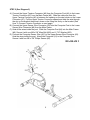
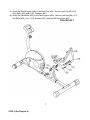
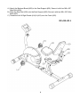
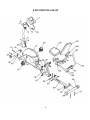
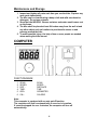
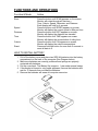
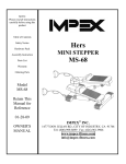
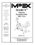
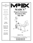
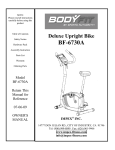
NOTE:
Please read all instructions
carefully before using this
product
Table of Contents
Safety Notice
MARCY RECUMBENT BIKE
PL-01012RP
Hardware Identifier
Assembly Instruction
Parts List
Warranty
Ordering Parts
Model
PL-01012RP
Retain This
Manual for
Reference
08-29-02
OWNER'S
MANUAL
IMPEX FITNESS PRODUCTS
14777 DON JULIAN RD., CITY OF INDUSTRY, CA 91746
Tel: (800) 999-8899 Fax: (626) 961-9966
www.impex-fitness.com
[email protected]
TABLE OF CONTENTS
BEFORE YOU BEGIN...................................................................................….
IMPORTANT SAFETY NOTICES..................................................................….
HARDWARE IDENTIFIER.....…....................................................................….
ASSEMBLY INSTRUCTIONS........................................................................….
EXPLODED DIAGRAM……………………………………………………………….
PARTS LIST...................................................................................................….
COMPUTER................................................................................................……
WARRANTY.................................................................................................….
ORDERING PARTS.......................................................................................…
1
2
3
4
9
10
11
13
13
BEFORE YOU BEGIN
Thank you for selecting the MARCY Recumbent Bike PL-01012RP by
IMPEX FITNESS PRODUCTS. For your safety and benefit, read this
manual carefully before using the machine. As a manufacturer, we are
committed to provide you complete customer satisfaction. If you have any
questions, or find there are missing or damaged parts, we guarantee you
complete satisfaction through direct assistance from our factory. To avoid
unnecessary delays, please call our TOLL-FREE customer service number.
Our Customer Service Agents will provide immediate assistance to you.
Toll-Free Customer Service Number
1-800-999-8899
Mon. - Fri. 9 a.m. - 5 p.m. PST
www.impex-fitness.com
[email protected]
1
IMPORTANT SAFETY NOTICE
PRECAUTIONS
This exercise machine is built for optimum safety. However, certain precautions apply
whenever you operate a piece of exercise equipment. Be sure to read the entire manual
before you assemble or operate your machine. In particular, note the following safety
precautions:
1. Keep children and pets away from the machine at all times. DO NOT leave
children unattended in the same room with the machine.
2. Only one person at a time should use the machine.
3. If the user experiences dizziness, nausea, chest pain, or any other abnormal
symptoms, STOP the workout at once. CONSULT A PHYSICIAN IMMEDIATELY.
4. Position the machine on a clear, leveled surface. DO NOT use the machine near water
or outdoors.
5. Keep hands away from all moving parts.
6. Always wear appropriate workout clothing when exercising. DO NOT wear robes or
other clothing that could become caught in the machine. Running or aerobic shoes are
also required when using the machine.
7. Use the machine only for its intended use as described in this manual. DO NOT use
attachments not recommended by the manufacturer.
8. Do not place any sharp object around the machine.
9. Disabled person should not use the machine without a qualified person or physician in
attendance.
10. Before using the machine to exercise, always do stretching exercises to properly warm
up.
11. Never operate the machine if the machine is not functioning properly.
12. The Maximum Weight Capacity is 300 lbs.
13. Read all warnings posted on the exercise bike.
14. Inspect the exercise bike for worn or loose component prior to use. Tighten/replace
any loose or wore components prior to use.
15. Care should be taken in mounting or dismounting the exercise bike.
16. This exercise bike is only for consumer use only.
WARNING: BEFORE BEGINNING ANY EXERCISE PROGRAM, CONSULT YOUR
PHYSICIAN. THIS IS ESPECIALLY IMPORTANT FOR INDIVIDUALS OVER THE AGE
OF 35 OR PERSONS WITH PRE-EXISTING HEALTH PROBLEMS. READ ALL
INSTRUCTIONS BEFORE USING ANY FITNESS EQUIPMENT. IMPEX INC. ASSUMES
NO RESPONSIBILITY FOR PERSONAL INJURY OR PROPERTY DAMAGE
SUSTAINED BY OR THROUGH THE USE OF THIS PRODUCT.
SAVE THESE INSTRUCTIONS.
2
3
ASSEMBLY INSTRUCTION
Tools Required Assembling the Machine: Two Adjustable Wrenches and Allen
Wrenches
NOTE: It is strongly recommended two or more people assembling this machine to
avoid possible injury.
STEP 1 (See Diagram1)
A.) Attach the Front Stabilizer (#10) to the Main Frame (#9). Secure it with two M10 x 3
1/8” Carriage Bolts (#11), ∅ 1” Bent Washers (#13), and M10 Acorn Nuts (#12).
B.) Slide the Seat Post (#16) onto the Rear Base (#23). Insert the Seat Adjustment Bolt
(#17) from the bottom through the open slot to hold the desired Seat position and
secure with a ∅ 7/8” Washer (#19) and Seat Adjustment Knob (#18).
C.) Attach the Rear Base (#23) to the Main Frame (#9). Secure it with six M8x 5/8” Allen
Bolts (#20) and ∅ 5/8” Washers (#21).
D.) Attach the Rear Stabilizer (#24) to the Rear Base (#23). Secure it with two M10 x 3
1/8” Carriage Bolts (#11), ∅ 1” Bent Washers (#13), and M10 Acorn Nuts (#12).
E.) Turn the End Caps on the Rear Base (#23) to adjust the stability of the Bases.
Diagram 1
4
STEP 2 (See Diagram 2)
A.) Connect the Upper Tension Connector (#6) from the Computer Post (#4) to the Lower
Tension Connector (#7) from the Main Frame (#9). Slide the cable wire from the
Upper Tension Connector (#6) in between the opening on the wire holder on the Lower
Connector (#7). Pull the Upper Tension Connector upward and slide the wire through
the slot on the bracket then drop it down so the fitting sits firmly on the bracket (See
How To Connect Tension Connector on next page).
B.) Connect the Upper Sensor Wire Connector (#3) from the Computer Post to the Lower
Sensor Wire Connector (#8) from the Main Frame.
C.) Hide all the wires inside the post. Slide the Computer Post (#4) into the Main Frame
(#9). Secure it with one M8 x 5/8” Allen Bolt (#20) and ∅ 7/8” Washer (#22).
D.) Connect the Computer Sensor Wire (#31) to the Upper Sensor Wire Connector (#3).
Hide the wires inside the post. Attach the Computer (#1) to the Computer Post.
Secure it with four M5 x 3/8” Philips Screws (#2).
DIAGRAM 2
5
HOW TO CONNECT TENSION CONNECTOR
Slide the Cable wire from the
Upper Tension Connector in
between the opening on the
wire holder on the Lower
Tension Connector.
Pull the Upper Tension
Connector upward
and slide the wire
through the slot on the
bracket.
Drop down the Connector
so the fitting sits firmly
on top of the bracket.
6
STEP 3 (See Diagram 3)
A.) Attach the Seat Support (#28) to the Seat Post (#16). Secure it with five M8 x 5/8”
Allen Bolts (#20) and ∅ 5/8” Washers (#21).
B.) Attach the Handlebar (#25) to the Seat Support (#28). Secure it with two M8 x 2 ¾”
Hex Bolts (#26), four ∅ 5/8” Washers (#21) and two M8 Nylon Nuts (#27).
DIAGRAM 3
7
STEP 4 (See Diagram 4)
A.) Attach the Backrest Board (#29) to the Seat Support (#28). Secure it with four M8 x 5/8”
Allen Bolts (#20).
B.) Place the Seat Pad (#30) onto the Seat Support (#28). Secure it with two M8 x 5/8” Allen
Bolts (#20).
C.) Thread the Left & Right Pedals (#14) & (#15) onto the Crank (#32).
DIAGRAM 4
8
EXPLODED DIAGRAM
9
PARTS LIST
KEY NO.
DESCRIPTION
1
2
3
4
5
6
7
8
9
10
11
12
13
14
15
16
17
18
19
20
21
22
23
24
25
26
27
28
29
30
31
32
33
34
Computer
M5 x 3/8” Philips Screw
Upper Sensor Wire Connector
Computer Post
Tension Adjustment Knob
Upper Tension Connector
Lower Tension Connector
Lower Sensor Wire Connector
Main Frame
Front Stabilizer
M10 x 3 1/8” Carriage Bolt
M10 Acorn Nut
∅ 1” Bent Washer
Left Pedal
Right Pedal
Seat Post
Seat Adjustment Bolt
Seat Adjustment Knob
∅ 7/8” Washer
M8 x 5/8” Allen Bolt
∅ 5/8” Washer
∅ 7/8” Bent Washer
Rear Base
Rear Stabilizer
Handlebar
M8 x 2 ¾” Hex Bolt
M8 Nylon Nut
Seat Support
Backrest Board
Seat Pad
Computer Sensor Wire
Crank
Front Roller Cap
Rear Stabilizer End Cap
10
QUANTITY
1
4
1
1
1
1
1
1
1
1
4
4
4
1
1
1
1
1
1
20
15
1
1
1
1
2
2
1
1
1
1
1
2
2
Maintenance and Storage
1. Inspect and tighten all parts each time you use the bike. Replace any
worn parts immediately.
2. The bike can be cleaned using a damp cloth and mild non-abrasive
detergent. Do not use solvents.
3. Store the bike INDOOR. Excess moisture and water would cause rust
on the frame.
4. The bike shall be placed at least 24 inches away from the wall or/and
any other object such as furniture to provide safe access to and
passage around the bike.
5. To avoid possible injury, the help of two or more people are needed
when moving the bike around.
COMPUTER
FUNCTION MARK
1.
2.
3.
4.
5.
6.
SCAN:
SPEED:
DIST.:
TIME:
ODO:
CAL.:
SCAN
SPEED
DISTANCE
TIME
ODOMETER
CALORIE
Note:
This computer is equipped with an auto on/off function.
The computer will turn on automatically if exercise is in motion.
If exercise stopped for over 4 minutes, the computer will turn off
automatically.
11
FUNCTIONS AND OPERATIONS
Function & Mode
Action
Scan
Press the button until SCAN appears on the screen.
Monitor will rotate through all functions –
Time, Calorie, Speed, Odometer, and Distance.
Each display will hold for 4 seconds.
Press the button until SPEED appears on screen.
Monitor will display the current speed in Mile per Hour.
Press the button until DIST appears on screen.
Monitor will display the distance has traveled.
Press the button until TIME appears on screen.
Monitor will display the accumulation of riding time.
Press the button until CAL appears on screen.
Monitor will display the calorie consumptions.
Press and hold the button for more than 2 seconds to
reset all data to 0.
Speed
Distance
Time
Calorie
Reset
HOW TO INSTALL BATTERY
1. Pull off the battery cover and place two SIZE-AA batteries into the battery
compartment on the back of the computer (See Diagram below).
2. Make sure batteries are correctly positioned and springs are properly
contacted with batteries.
3. Put the cover back. The Battery life is approx. 1 year under normal usage.
4. If the display is blurred or only partial appeared, remove the batteries and
wait for 15 seconds then re-install the batteries.
5. Remove the batteries will erase all computer memories.
12
IMPEX INC.
LIMITED WARRANTY
IMPEX Inc. ("IMPEX") warrants this product to be free from defects in workmanship and material,
under normal use and service conditions, for a period of two years on the Frame from the date of
purchase. This warranty extends only to the original purchaser. IMPEX's obligation under this
Warranty is limited to replacing or repairing, at IMPEX's option.
All returns must be pre-authorized by IMPEX. Pre-authorization may be obtained by calling IMPEX
Customer Service Department at 1-800-999-8899. All freights on products returned to IMPEX must
be prepaid by the customer. This warranty does not extend to any product or damage to a product
caused by or attributable to freight damage, abuse, misuse, improper or abnormal usage or repairs
not provided by an IMPEX authorized service center or for products used for commercial or rental
purposes. No other warranty beyond that specifically set forth above is authorized by IMPEX.
IMPEX is not responsible or liable for indirect, special or consequential damages arising out of or in
connection with the use or performance of the product or other damages with respect to any
economic loss, loss of property, loss of revenues or profits, loss of enjoyments or use, costs of
removal, installation or other consequential damages or whatsoever natures. Some states do not
allow the exclusion or limitation of incidental or consequential damages. Accordingly, the above
limitation may not apply to you.
The warranty extended hereunder is in lieu of any and all other warranties and any implied
warranties of merchantability or fitness for a particular purpose is limited in its scope and duration to
the terms set forth herein. Some states do not allow limitations on how long an implied warranty
lasts. Accordingly, the above limitation may not apply to you.
This warranty gives you specific legal right.
to state. Register
You may also have other rights which vary from state
on-line www.impex-fitness.com
IMPEX INC.
14777 Don Julian
City of Industry, CA 91746
ORDERING REPLACEMENT PARTS
Replacement parts can be ordered by calling our Customer Service Department toll-free at 1-800999-8899 during our regular business hours: Monday through Friday, 9 am until 5 pm Pacific
standard time.
[email protected]
When ordering replacement parts, always give the following information.
1.
2.
3.
4.
Model
Description of Parts
Part Number
Date of Purchase
13