1
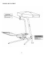
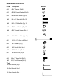
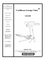
NOTE:
Please read all instructions
carefully before using this
product
Caribbean Lounge Chair
®
Table of Contents
Safety Notice
GD-800
Hardware Pack
Assembly Instruction
Parts List
Warranty
Ordering Parts
Model
GD-800
Retain This
Manual for
Reference
11-21-06
OWNER'S
MANUAL
IMPEX® INC.
14777 DON JULIAN RD., CITY OF INDUSTRY, CA 91746
Tel: (800) 999-8899 Fax: (626) 961-9966
www.impex-fitness.com
[email protected]
TABLE OF CONTENTS
BEFORE YOU BEGIN......................................................................................
IMPORTANT SAFETY NOTICES.....................................................................
HARDWARE IDENTIFIER……......…...............................................................
ASSEMBLY INSTRUCTIONS...........................................................................
OPERATION………………………………………………………………………….
EXPLODED DIAGRAM.........................................................................……….
PARTS LIST......................................................................................................
WARRANTY.................................................................................................….
ORDERING PARTS.......................................................................................…
1
2
3
5
19
20
21
22
22
BEFORE YOU BEGIN
Thank you for selecting the Caribbean Lounge Chair GD-800 by IMPEX®. For
your safety and benefit, read this manual carefully before using the machine.
As a manufacturer, we are committed to provide you complete customer
satisfaction. If you have any questions, or find there are missing or damaged
parts, we guarantee you complete satisfaction through direct assistance from
our factory. DO NOT RETURN THE UNIT TO THE STORE! To avoid
unnecessary delays, please call our TOLL-FREE customer service number.
Our Customer Service Agents will provide immediate assistance to you.
Toll-Free Customer Service Number
1-800-999-8899
Mon. – Fri. 9 a.m. – 5 p.m. PST
www.impex-fitness.com
[email protected]
1
IMPORTANT SAFETY NOTICE
Please read the entire manual before assembling or operating the equipment. In particular,
note the following safety precautions to reduce the likelihood of injury.
1. Children must be supervised at all times and never left unattended with the unit.
2. Make sure the surfaces are free of objects that may cause tipping over.
3. Place the equipment on level ground, not less than 6 ft (1.8 m) from any structure or
obstruction such as fence, garage, house, overhanging branches, laundry lines, or
electrical wires.
4. Lock the Caribbean Lounge Chair with the Cables when not in use.
5. Make sure bystanders are at least 5 feet away from the equipment while it is in motion. No
one should be allowed to walk close to, in front of, behind, or between moving items.
6. Keeps hands away from the pivot area.
7. Do not stand on the Caribbean Lounge Chair. This could cause the bed to tip over and
result in injury.
8. The Caribbean Lounge Chair is not designed to use by children or handicap persons.
9. Maximum user’s weight capacity 300 lbs.
10. Only one person should be using the Caribbean Lounge Chair at a time.
Care and Maintenance
1. Periodically inspect all parts. Check all nuts and bolts twice monthly during the usage
season for tightness and tighten as required. It is particularly important that this procedure
be followed at the beginning of each season.
2. Replace any worn and damaged part immediately. Check all coverings for bolts and sharp
edges twice monthly during usage season to be certain they are in place. Replace when
necessary. It is especially important to do this at the beginning of each new season.
3. Use mild household spray cleaners and/or a damp rag to wipe clean. Do not use harsh
cleaning chemicals.
4. Sand rusted areas on tubular members and repaint using a nonlead-based paint meeting
the requirements of Title 16 CFR Part 1303.
5. Disposal Instructions – The equipment can be safely disassembled and disposed without
unreasonable hazards. Call your local recycle agency regarding details of recycling.
6. Inspect before and periodically during use for frayed ropes and torn seam. Call the
customer service department if any defects were found.
7. Inspect before and periodically during use for excessive rust, integrity of the welds, and
twist in hanging hardware. Call the customer service department if any defects were
found.
SAVE THESE INSTRUCTIONS.
2
WARNING LABEL PLACEMENT
3
HARDWARE IDENTIFIER
Part#
Description
#12
Ø ¾” Washer (Qty 6)
#13
Ø 5/8” Curved Washer (Qty 8)
#14
Ø 5/8” Lock Washer (Qty 8)
#15
M8 x ¾” Allen Bolt (Qty 12)
#16
M10 x ¾” Allen Bolt (Qty 12)
#17
Ø ¾” Lock Washer (Qty 12)
#18
Ø ¾” Curved Washer (Qty 6)
#20
Ø 1 1/8” Cover Cap (Qty 14)
#21
M12 x 4 ½” Allen Bolt (Qty 4)
#22
Ø1” Washer (Qty 8)
#23
M12 Aircraft Nut (Qty 4)
#27
Ø 5/8” Washer (Qty 4)
#31
M8 Aircraft Nut (Qty 4)
#42
M6 x ½” Allen Bolt (Qty 6)
#43
Ø ½” Lock Washer (Qty 6)
Identifier
Tools:
4# Allen Wrench (Qty 1)
6# Allen Wrench (Qty 1)
8# Allen Wrench (Qty 1)
4
ASSEMBLY INSTRUCTION
Tools Required Assembling the Machine: Two Adjustable Wrenches and Allen Wrench
NOTE: It is strongly recommended two or more people assembling this machine to avoid
possible injury.
STEP 1-1 (See Diagram 1-1)
A.) Attach the Left & Right Main Post Support (#25 & #26) to the Main Post (#24) from each side.
B.) Align the holes and securely tighten them together with four M12 x 4 ½” Allen Bolts (#21), eight Ø 1”
Washers (#22), and four M12 Aircraft Nuts (#23).
C.) Cover all Bolts and Nuts with eight Ø 1 1/8” Cover Caps (#20). See Note on next page.
DIAGRAM 1-1
5
Note:
When installed the Ø 1” Washer, make sure the lip of the washer faces outside, away from the
frame. The groove inside the Plastic Cover should clip onto the lip of the Washer.
6
Step 1-2 (See Diagram 1-2)
A.) Insert the Upper Frame (#8) into the opening on the Main Post (#24).
B.) Securely tighten them together with six M10 x ¾” Allen Bolts (#16), Ø ¾” Lock Washers (#17),
and Ø ¾” Washers (#12).
C.) Cover all Bolts with six Ø 1 1/8” Cover Caps (#20).
DIAGRAM 1-2
7
Step 2-1 (See Diagram 2-1)
A.) Insert the Lower Cantilever (#28) into the Upper Cantilever (#9).
B.) Securely tighten them together with six M10 x ¾” Allen Bolts (#16), Ø ¾” Lock Washers (#17),
and Ø ¾” Curved Washers (#18).
DIAGRAM 2-1
8
Step 2-2 (See Diagram 2-2)
A.) Attach the Right & Left Connecting Tube (#10 & #11) onto the Upper Cantilever (#9) from
each side.
B.) Insert one Lounge Chair Side Frame (#32) into the Right Connecting Tube (#10).
C.) Slide the right sleeve on the Nylon Sheet (#35) onto the Lounge Chair Side Frame and all the
way up to position A shown in the diagram.
D.) Slide the left sleeve on the Nylon Sheet onto the Left Connect Tube (#11) to position B shown
in the diagram.
E.) Pull back the right sleeve on the Nylon Sheet to position C shown in diagram. Make sure the
rivet holes on the Nylon Sheet are parallel to the Right & Left Connecting Tubes.
DIAGRAM 2-2
9
Step 2-3 (See Diagram 2-3)
A.) Insert the other Lounge Chair Side Frame (#32) through the left sleeve on the Nylon Sheet
(#35) all the way into the Left Connect Tube (#11).
B.) Insert the Lounge Chair End Frame (#33) into the two Lounge Chair Side Frames (#32).
DIAGRAM 2-3
10
Step 2-4 (See Diagram 2-4)
A.) Secure the Lounge Chair Side Frames (#32) to the Connecting Tubes (#10 and 11) with two
M8 x ¾” Allen Bolts (#15), Ø 5/8” Lock Washers (#14), and Ø 5/8” Curved Washers (#13).
B.) Secure the Lounge Chair End Frame (#33) to the two Lounge Chair Side Frames with two M8
x ¾” Allen Bolts (#15), Ø 5/8” Lock Washers (#14), and Ø 5/8” Curved Washers (#13).
DIAGRAM 2-4
11
Step 2-5 (See Diagram 2-5)
A.) Attach the Lounge Chair Support (#30) to the two Lounge Chair Side Frames (#32).
B.) Secure it with four M8 x ¾” Allen Bolts (#15), Ø 5/8” Lock Washers (#14), and Ø 5/8” Curved
Washers (#13).
DIAGRAM 2-5
12
Step 2-6 (See Diagram 2-6)
A.) Attach the Lounge Chair Support (#30) onto the bracket on the Lower Cantilever (#28).
B.) Secure it with four M8 x ¾” Allen Bolts (#15), one Bracket (#29), four Ø 5/8” Washers (#27),
and four M8 Aircraft Nuts (#31).
DIAGRAM 2-6
13
Step 3-1 (See Diagram 3-1)
A.) Insert four Support Tubes (#3) that are in diagonal direction to each other into the holes on the
Canopy Support Frame (#5).
B.) Secure each Support Tube with one M6 x ½” Allen Bolt (#42) and Ø ½” Lock Washer (#43).
C.) Insert the other two Tubes into the Canopy Support Frame (#35) without tightening them.
DIAGRAM 3-1
14
Step 3-2 (See Diagram 3-2)
A.) Insert the end of the Tubes (#3) into the pockets on the Canopy (#1).
DIAGRAM 3-2
15
Step 3-3 (See Diagram 3-3)
A.) Push out the two Support Tubes (#3) that were not tightened in step 3-2 above, away from the
center.
B.) Secure each Support Tube to the Canopy Support Frame with one M6 x ½” Allen Bolt (#42)
and Ø ½” Lock Washer (#43).
DIAGRAM 3-3
16
Step 4-1 (See Diagram 4-1)
A.) Hang the Cantilever Hook (#40) onto the Upper Frame Hook (#41).
B.) Attach two Cables (#19) to the hook underneath the Upper Cantilever (#9).
DIAGRAM 4-1
17
Step 4-2 (See Diagram 4-2)
A.) Use the Nylon Sheet String (#34) to secure the Nylon Sheet to the Lounge Chair End Frame
(#33). Use the String (#37) to secure the Sheet to the Connecting Tubes.
B.) Place the Pillow (#36) onto the Nylon Sheet. Secure it with the Velcro strap.
C.) Insert the tube on the Canopy Support Frame (#5) into the pivot on the Upper Frame (#8).
Secure it with a Lock Knob (#6).
D.) To adjust the Canopy position, loosen and pull the Lock Knob. Then turn the Canopy Support
Frame to obtain the desired position.
E.) Attach the other end of the two Cables (#19) to the hooks on the Left & Right Main Post
Support (#25 & #26) to lock the Lounge Chair when not in use.
DIAGRAM 4-2
18
OPERATION
1. The chair can be used with or without the bottom cables attached. It is recommended to use the
cables attached until you are familiar with the motion of the lounge chair.
2. Only sit on the bed from the mid section of the bed with both hands holding onto the bed frames.
DO NOT sit on the edge or the end of the bed. That would cause the bed to tilt over and cause
injury.
3. When you first sit on the bed, the bed will rock back and forth. That is normal. It takes a little
time to get used to the motion.
4. Only lay on the bed with your head on the pillow.
5. The Canopy can be swing away by simply turn and pull the Knob on the pivot.
19
EXPLODED DIAGRAM
20
Parts list
KEY NO.
DESCRIPTION
Q’ty
1
2
3
4
5
6
7
8
9
10
11
12
13
14
15
16
17
18
19
20
21
22
23
24
25
26
27
28
29
30
31
32
33
34
35
36
37
38
39
40
41
42
43
44
Canopy
Support Tube End Cap
Support Tube
Cone-shaped Canopy Support End Cap
Canopy Support Frame
Lock Knob
M6 Allen Screw
Upper Frame
Upper Cantilever
Right Connecting Tube
Left Connecting Tube
Ø ¾” Washer
Ø 5/8” Curved Washer
Ø 5/8” Lock Washer
M8 x ¾” Allen Bolt
M10 x ¾” Allen Bolt
Ø ¾” Lock Washer
Ø ¾” Curved Washer
Cable
Ø 1 1/8” Cover Cap
M12 x 4 ½” Allen Bolt
Ø 1” Washer
M12 Aircraft Nut
Main Post
Left Main Post Support
Right Main Post Support
Ø 5/8” Washer
Lower Cantilever
Bracket
Lounge Chair Support
M8 Aircraft Nut
Lounge Chair Side Frame
Lounge Chair End Frame
Nylon Sheet String
Nylon Sheet
Pillow
Pillow String
Ø 1” Hook End Cap
M12 Hook Lock Nut
Cantilever Hook
Upper Frame Hook
M6 x ½” Allen Bolt
Ø ½” Lock Washer
Ø 1” End Cap
1
6
6
6
1
1
2
1
1
1
1
6
8
8
12
12
12
6
2
14
4
8
4
1
1
1
4
1
1
1
4
2
1
1
1
1
1
1
2
1
1
6
6
1
21
®
IMPEX INC.
LIMITED WARRANTY
®
IMPEX INC ("IMPEX ") warrants this product to be free from defects in workmanship and material, under
normal use and service conditions, for a period of 2 YEARS from the date of purchase. This warranty extends
only to the original purchaser. IMPEX's obligation under this Warranty is limited to replacing or repairing, at
IMPEX's option.
All returns must be pre-authorized by IMPEX. Pre-authorization may be obtained by calling IMPEX Customer
Service Department at 1-800-999-8899. All freights on products returned to IMPEX must be prepaid by the
customer. This warranty does not extend to any product or damage to a product caused by or attributable to
freight damage, abuse, misuse, improper or abnormal usage or repairs not provided by an IMPEX authorized
service center or for products used for heavy commercial or rental purposes. No other warranty beyond that
specifically set forth above is authorized by IMPEX.
IMPEX is not responsible or liable for indirect, special or consequential damages arising out of or in connection
with the use or performance of the product or other damages with respect to any economic loss, loss of
property, loss of revenues or profits, loss of enjoyments or use, costs of removal, installation or other
consequential damages or whatsoever natures.
Some states do not allow the exclusion or limitation of
incidental or consequential damages. Accordingly, the above limitation may not apply to you.
The warranty extended hereunder is in lieu of any and all other warranties and any implied warranties of
merchantability or fitness for a particular purpose is limited in its scope and duration to the terms set forth herein.
Some states do not allow limitations on how long an implied warranty lasts. Accordingly, the above limitation
may not apply to you.
This warranty gives you specific legal right.
You may also have other rights which vary from state to state.
Register on-line at www.impex-fitness.com
®
IMPEX INC.
14777 Don Julian Rd.,
City of Industry, CA 91746
ORDERING REPLACEMENT PARTS
Replacement parts can be ordered by calling our Customer Service Department toll-free at 1-800-999-8899
during our regular business hours: Monday through Friday, 9 am until 5 pm Pacific standard time.
[email protected]
When ordering replacement parts, always give the following information.
1. Model
2. Description of Part
3. Part Number
4. Date of Purchase
22