1
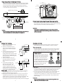
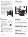
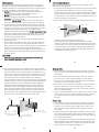
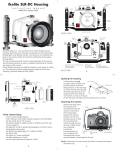
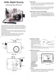
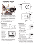
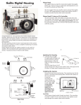
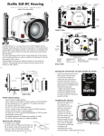
Ikelite Digital Housing
i n s t r u c t i o n
m a n u a l
Shutter
Release
Off
Continous
Flash
Pop-Up Flash
Mode
Quick Release
Button
#6140.05 for Canon PowerShot S5 IS
Zoom
Macro/
Manual
Focus
Lens Port
Rubber
Handles
Lid
Snap
Lid
Snap
Tray
Base
FRONT VIEW
O'ring
Congratulations on your purchase of an Ikelite Digital Camera
Housing. Ikelite has over 30 years of experience in the underwater
photographic and lighting market. Our products are designed and
built in the USA by Ikelite for both the professional and amateur
photographer.
The clear housing permits instant visual inspection of the camera
and all sealing surfaces as well as complete monitoring of controls
and camera LCD screens.
Ikelite Digital Housings are slightly negative in salt water for
stability. This housing has been water pressure tested at the
factory. Housing is pressure tested to 200’ (60m).
Shutter
Release
TTL
Sync Cord
Connector
Mode
Shortcut
Function
ISO
Display
Lid
Omni
Selector
Movie
Set
Lid
Menu
Snap
Snap
BACK VIEW
2
Opening the Housing
Zoom
Lens Port
Shutter
Release
Macro/
Manual Focus
Continous
Pop-Up Flash
Off
Flash
Installing the Camera
Mode
TTL Sync Cord
Connector
Mode
TOP VIEW
3
Push Forward
1. Lid Snaps have a Lock.
To open, push Lid Snap Lock
Lid Snap Lock
forward and lift as shown.
Keep pressure on the Lid
Snap so it does not fly open
quickly.
Lift
Some lid snaps have a lot of
spring tension once they go over center, have a firm grip on the
lid snap. Lid Snaps may be opened one at a time.
1. Remove the back from
O' Ring
Lid
the housing. The
Hook
Housing Back
mounting tray for the
camera is secured to
the housing back.
Position the camera on
the tray and secure it
with the mounting bolt
which threads into the
camera’s tripod socket.
Use a coin or flat
bladed screwdriver to
Mounting
Mounting
Tray
tighten the mounting
Bolt
bolt so the camera is
flat against the tray.
CAUTION:
Some camera tripod socket threads are plastic. The mounting
tray bolt is metal. Do not cross thread or over tighten as you
may damage the camera tripod socket threads.
2. Pull out on each housing control until it stops. This will get the
controls out of the way for installing the camera.
4
Flash Connection for External Strobes
When using an external strobe connect the housings Hot Shoe
Connector. Slide the connector into the hot shoe of the camera
from the back of the camera as shown. Slide the connector
forward until it stops. This should be done before the camera
is secured with the mounting bolt.
Silver
Mounting Bracket
Top Edge
of Housing
Hot Shoe
External Strobe Connector
Waterproof Cap (see caution)
O’ring
Housing Back
Silver
Mounting
Bracket
Hot Shoe
Connector
Camera
Caution:
Do not remove the External Strobe Connector’s waterproof cap
unless an external sync cord is going to be plugged in.
If you are not using the External Flash Connection
Store the hot-shoe by sliding it into the silver bracket located on
the inside back of the camera housing as shown. This can be done
after the camera is mounted to the mounting tray.
CAUTION
Only remove the WaterProof cap from the external strobe
connector on the back of the housing when an external strobe
will be connected.
5
Closing the Housing
housing back
1. Place housing face down in your
lap or on a flat surface.
2. Check to see that there is an
o’ring on the housing back and
that it is clean and in its proper
location.
3. Guide the back onto the housing.
o’ring
The o’ring should touch the
housing all the way around. There
housing
should be an even gap all the way
around between the housing and
the housing back.
4. Lift the lid snaps so they are
housing back
extended and place the lid snap
into the hook on the housing
back.
5. To close the housing push
even gap
all 4 sides
down on the lid snaps until
they snap into place . Lid
snaps on opposite sides of the
o’ring
housing should be closed at the
housing
same time. Be sure they are down
far enough to engage the lock.
Double check - Once the housing is closed, check the o’ring seal.
Check the gap between the housing back and the housing, it
should be even all the way around.
Look through the clear plastic back at the o’ring. You should see
a darkened area where the o’ring is compressed against the
housing back. If you do not see an even black compression seal
all the way around the back, open the lid snaps, reseat the
housing back and close the lid snaps. Visually check the seal again.
7
6
Checking Controls
Once the housing has been closed, push the controls back into
place. Make sure they line up with the camera’s controls.
Turn Camera On
Turn the camera on and operate each of the housing controls
to get a feel for using the camera in the housing. Take a few
pictures above water with the camera in the housing.
Zoom Control
(NOTE:) After you have used the
housing's zoom control it must be
returned to the center position to
disengage. If the housing zoom
control is pushing the zoom lever
in either direction you may not
be able to take a picture or access
any other function as the camera
is receiving a signal from the
engaged zoom control.
Lubricants
-
+
Zoom control
engaged
-
+
Zoom control
disengaged
(centered)
1. Ikelite provides silicone lubricant with the housing. We recommend
you use only Ikelite lubricant on Ikelite products as some other
brands may cause the o’ring to swell and not seal properly.
2. Use only enough lubricant to lightly cover control shafts and
o’rings. Wipe off any excess lubricant with a clean cloth.
Lubricant is not a sealant, it is used to reduce friction. Excessive
lubricant can collect sand and dirt which may interfere with
proper sealing.
CAUTION
Never use spray lubricants as the propellant ingredient can
cause the plastic housing to crack.
8
Lens Port
The Lens Port is factory sealed, do not remove.
Treat the glass in the lens port as a camera lens. After use, rinse
and gently dry the lens port to avoid water spotting. To clean
use a mild soap solution or lens cleaner.
Do not use alcohol or window cleaner on the Lens Port.
The Lens Port is threaded so that accessory lenses can be
screwed onto the port. The threads are very fine, take care not
to cross thread accessory lenses.
The housing port has a 67mm thread which accepts the optional
#6420 Ikelite W-20 Wide-Angle Lens and other manufacturers
(67mm) screw thread style lenses. These lenses can be screwed
onto the lens port above or below water. These lenses are
designed to have water between the front of the port and the
accessory lens. Make sure no air bubbles are trapped between
the port and the accessory lens. There may be slight vignetting
when these wide angle lenses are installed. Any vignetting that
occurs can be eliminated
Wide Angle Lens
by zooming the camera
lens slightly. To properly
light subjects when using
a wide angle lens an
external strobe should
be used. Due to the wide
coverage of the wide
angle lenses, the DS125
Substrobe is recommended
or two DS51 Substrobes.
9
To install the diffuser or deflector
spread the port clamp at the
spring end and slide over the lens
port. The white plastic should be
placed in front of the camera flash.
The port clamp should be pushed back
against the front of the housing.
Diffuser
Diffuser & Deflector Installation
Diffuser
10
Housing shown with
diffuser installed.
Using TTL Flash Exposure with
External Ikelite DS Substrobes (Recommended)
Diffuser/Deflector
material
+
+
Port Clamp
Spring
Spread to Install
The deflector should be installed when using an external strobe
such as the DS51 or DS125 Substrobe and DS Sensor. The
deflector is required when using the camera’s built-in flash to
trigger the EV Controller. The deflector will redirect the
camera’s flash to the DS Sensor or EV Controller which controls
the external strobe.
11
If you do not have an external flash the camera’s built-in flash
can be used. See Diffuser instructions.
Using External Strobes
The diffuser should be installed when using the camera’s built
in flash. When shooting with the camera’s built-in flash at
approximately 2 feet (0.6 m) or less, zoom the lens to
maximum telephoto. The lens port on the housing blocks a
portion of the light from the camera’s built-in flash when
shooting close up. If you do not zoom to maximum telephoto,
a shadow may appear in the lower left corner of close-up
photographs. (You can test this above water)
Deflector
Using the Camera’s Built-in Flash.
Housing shown with
accessory wide angle lens.
Diffuser and Deflector cont.
A diffuser and deflector are
included with the housing. The
diffuser is white transparent
plastic. The deflector is also
white but is not transparent.
Using Flash
This housing has Conversion Circuitry built into the housing.
When used with current model Ikelite DS Substrobes the
Conversion Circuitry provides Canon eTTL flash exposure. In the
TTL mode the camera controls the light output of the external
strobe(s) to obtain properly exposed images. The Conversion
Circuitry is powered by the Ikelite DS Substrobe when
connected to the housing with the #4103.51 single or #4103.52
dual sync cords with a blue band. See page 13 for DS Substrobe
compatibility with Conversion Circuitry.
Using Manual Exposure with External DS Substrobes
Any Ikelite DS Substrobe(s) can be used in the manual mode
when connected with the #4103.51 single or #4103.52 dual sync
cord with a blue band. In the manual mode different power
settings on the DS Substrobe can be selected to obtain a
properly exposed image.
Using Ikelite Non-DS Substrobes (Substrobes 50 , 100 A,
200, 400) with this housing.
The Conversion Circuitry is automatically disabled when used
with a Non-DS Substrobe. These Substrobes can be used in their
manual mode utilizing any power settings provided on the
Substrobe.
Using Non Ikelite Strobes with this Housing
The Conversion Circuitry is automatically disabled when used
with a Non Ikelite strobe. These strobes can be used in their
manual mode utilizing any power settings provided on the strobe.
12
NOTE: DS Substrobe Up-date may be required.
DS50 Substrobes
• DS50 SubStrobes with a Serial Number below 63,850 can not be
updated to operate with the Conversion Circuitry.
• DS50 SubStrobes with a Serial Number between 63,850 and
69,999 operate with the Conversion Circuitry, but require update
to provide optimum performance.
• DS50 Substrobe with a Serial Number of 70,000 or higher or
with one of the two following labels in the battery compartment
provide optimum performance with the Conversion Circuitry.
DS125 Substrobes
• DS125 Substrobes with a Serial Number below 2,500 must be
updated to operate correctly with the Conversion Circuitry.
• DS125 Substrobes with a Serial Number between 2,501 and
4,900 operate with the Conversion Circuitry but require update
to provide optimum performance.
• DS125 Substrobe with a Serial Number of 5,000 or higher or
with one of the two following labels in the battery compartment
provide optimum performance with the Conversion Circuitry.
Optional Accessories
Substrobe
DS51
Substrobe DS51 Packages
Package #3944.45
Includes:
DS51 Digital Substrobe
Ikelite TTL Sync Cord
Strobe Arm Is #4075.1
Package #3944.51
Includes:
Sync
DS51 Digital Substrobe
Cord
Ikelite TTL Sync Cord
Strobe Arm #4086.61 (ball socket arm)
Strobe
Arm
The DS51 Digital Substrobe is equally
suited for general and wide-angle
photography, covering up to 80° with
the diffuser. Powered by four AA-size batteries, the compact
size of the DS51 makes it ideal for macro photography.
Ikelite Photocase
Waterproof equipment carrying case featuring die-cut foam
openings to accommodate the camera housing, strobes,
mounting arms, etc.
Photocase #3940 .4 with die-cut foam.
For Substrobe Up-Date:
Contact Ikelite for information.
ikelite
Substrobe
MOD-NC
serial number
13
serial number
Optional Accessories, cont.
Substrobe DS125 Packages
Substrobe
DS125
Package #3944.75
Includes:
DS125 Digital Substrobe
1.5-hour Smart Charger 110/240V
Ikelite TTL Sync Cord
Strobe Arm #4086.61 (ball socket arm)
The Ikelite DS125 digital Substrobe
combines high intensity output and
wide 100° angle of coverage with
Strobe
the diffuser, in a compact, versatile Arm
design. The easily interchangeable
and rechargeable NiMH battery
pack recycles in 1.0 second. Built-in
modeling light / night diving light.
14
Optional Accessories
Back O’ring #0132.59
O’rings last for several years if properly maintained. (See
maintenance) Always carry a spare.
UR/Pro Filter (Blue Water) #6441.41
The UR/Pro underwater color correcting filter is designed to
restore some of the warm colors filtered out by the water. For
available light use only, not recommended for use with flash.
Green Water Filter #6441.81
Sync
Cord
Enhances contrast and alters the color of green water to give
our subject a rich, natural tone. For available light only, not
recommended for use with flash.
Use the EV Controller with a DS Substrobe
The EV Controller provides 10 manual power settings in 1/2 stop
increments for the DS51 or DS125 Substrobes. The EV Controller has
a built-in slave which can be triggered by the camera’s built-in flash.
Ikelite W-20 Wide-Angle Lens #6420
Wide-Angle lenses allow you to capture more of the scene and
get closer to your subject which results in clearer images and
more vivid color. Can be installed or removed underwater for
maximum versatility. (Note: some housings may require an
adapter, see instructions.)
Substrobe Packages available
15
Ikelite Ball Arm Systems are provided with these packages
#3944.45 SubStrobe DS51 with Sync Cord & Strobe Arm
#3944.51 SubStrobe DS51 with Sync Cord & Ball Socket Arm
#3944.75 SubStrobe DS125 with Sync Cord & Ball Socket Arm
16
Maintenance
The Ikelite Digital Housing should be given the same care and
attention as your other photographic equipment. In addition to
normal maintenance we recommend that the housing be returned
to Ikelite periodically to be checked and pressure tested.
1. Do Not leave the camera and housing in direct sunlight for
prolonged periods. Heat may damage the camera.
2. Do Not ship the camera in the housing.
3. Before using the housing, always check the tightness of the
set screw in each control knob.
Check each control gland to make sure they are tight. There
is a slight chance that either could vibrate loose during travel.
4. Keep the back o’ring clean and lightly lubricated. To lubricate
remove the o’ring from the back. Put a small amount of lkelite
lubricant on your fingers. Draw the o’ring through your fingers
to apply a light coating of lubricant. Only apply enough
lubricant to make the o’ring feel slick. Do Not stretch the o’ring.
This light coating of lubricant will help to keep the o’ring from
drying out and will help to show a dark sealing line when the
housing back is properly sealed.
5. Keep the area where the o’ring fits and the sealing surface of
the housing clean.
6. Rinse the housing exterior in fresh water after each salt water
use. Dry with a soft cloth. Dry lens port to eliminate spotting.
After several uses in salt water soak the housing in a mild soap
solution, rinse and dry before storage. When storing the
housing, remove the back o’ring, lightly lubricate and place in a
plastic bag. Place the plastic bag with o’ring inside the housing
for safe keeping.
Control Maintenance
Ikelite controls are designed to provide years of reliable service
with minimal maintenance.
1. Push button controls require no maintenance other than rinsing
in fresh water after saltwater use. If a push button control
becomes difficult to push or if it sticks when depressed, soak the
housing in luke warm fresh water. After a few minutes operate
the push button. If this does not correct the problem, return the
housing to Ikelite for maintenance.
2. Some of the controls have long shafts. These controls can be
lubricate shaft
housing
pull out to
expose shaft
pulled out, exposing the shaft (see drawing).
To lubricate the control, gently pull on the knob until the
stainless steel shaft is exposed. Lightly lubricate the shaft, then
move the shaft in and out several times. This will lubricate the
x’ring in the Ikelite control gland. This should be done before
using the housing after a prolonged storage period, or once a
week when the housing is in use.
CAUTION
Never use spray lubricants as the propellant ingredient can
cause the plastic housing to crack.
17
3. Some of the controls have a short shaft and cannot be pulled
out exposing the shaft for lubrication. In the unlikely event one
of these controls sticks or becomes difficult to operate you can
remove the control from the housing and lubricate it, or return
the housing to Ikelite for maintenance. To remove the control,
loosen the set screw in the knob (allen wrench required);
remove the knob. If there is salt or dirt build-up on the exposed
control shaft, clean the shaft. Open the housing and gently slide
the control shaft out of the control gland. Clean and lightly
lubricate the shaft, including the end of the shaft. Slide the
shaft back into the control gland and gently slide it back and
forth a few times without fully removing the shaft from the
gland. Replace the knob, NOTE the flat area on the shaft, the
set screw in the knob should tighten down against the flat area
on the control so the knob does not turn on the shaft.
control
shaft
Flat
Tighten set screw down
against this area when
replacing the knob.
housing
Loosen set screw
(allen wrench required)
19
General Tips
1. Due to the power required to operate the camera, flash, and
LCD screen it is a good idea to start each dive with a fresh set
of batteries.
2. Some cameras reset their flash to AUTO when the camera is
turned on. If you prefer another setting be sure to select it.
3. As soon as you enter the water, take a moment and check the
housing to see that it is properly sealed.
4. Next, check to see if there are any bubbles on the face of the
lens port. If there are, take your finger and remove them. If
there are bubbles on the lens port they can produce soft focus
spots in your photographs.
5. If you use the housing Zoom control, make sure to move it back
to the center position. If the housing Zoom control is pushing
the camera zoom lever to either side the camera will not
function.
Photo Tips
gland
Lubricate end of shaft
before reinserting into
gland
18
1. The number one rule in underwater photography is eliminate
as much water between camera and subject as possible. Get
as close as you can to the subject, then use the zoom. If you
are using flash, subjects beyond 6 feet (1.8m)will not have
much color.
2. Digital cameras have a slight lag time between when you press
the shutter release button and the camera actually takes the
picture. Hold the camera steady a second or two after pressing
the shutter release button.
3. Do not shoot down on subjects as they will quite often blend
into the background and be difficult to see in the photograph.
Shoot subjects straight on or shoot up at a slight angle using
the blue water as a contrasting background.
20
Photo Tips Cont.
4. Underwater flash is used to restore the warmer colors filtered
out by the water as well as to illuminate the subject. When
photographing underwater, set the camera to use flash on
every shot. If the camera’s flash is set to AUTO and the sun is
behind your subject, the camera may see enough light that it
does not fire the flash. With the sun behind the subject the
subject is shaded (dark) and needs flash for a good exposure.
5. Since opinions vary on what is the correct exposure you may
want to adjust your camera for what you like exposure wise.
Many cameras allow you to adjust both available light and flash
exposure with an EV control.
6. Many photographers transfer their images to the computer
where they can fine tune the appearance of the image. Many
of the image manipulation programs make you think you can
magically correct any image taken and make a good picture.
One thing to remember when using image manipulation
programs, if the image is overexposed much of the color is
missing. If the color is missing you cannot adjust it. If images
are underexposed some color and detail may be there, it is just
dark and you can adjust it to some degree. So if you error in
exposure it is better to have the image slightly underexposed
than over exposed.
Notes:
____________________________________________________________________
____________________________________________________________________
____________________________________________________________________
____________________________________________________________________
____________________________________________________________________
____________________________________________________________________
____________________________________________________________________
____________________________________________________________________
____________________________________________________________________
____________________________________________________________________
____________________________________________________________________
____________________________________________________________________
____________________________________________________________________
____________________________________________________________________
____________________________________________________________________
____________________________________________________________________
____________________________________________________________________
_________________________________________________________________ .
22
21
Notes:
____________________________________________________________________
____________________________________________________________________
____________________________________________________________________
____________________________________________________________________
____________________________________________________________________
____________________________________________________________________
____________________________________________________________________
____________________________________________________________________
____________________________________________________________________
____________________________________________________________________
____________________________________________________________________
____________________________________________________________________
____________________________________________________________________
____________________________________________________________________
____________________________________________________________________
____________________________________________________________________
____________________________________________________________________
Ikelite Limited Warranty
All Ikelite products are warranted against any manufacturing
defects for a period of one year from the date of purchase.
Defective products should be returned prepaid to Ikelite. Ikelite
will, at its discretion, repair or replace such products, and will
return to customer prepaid. All other claims, of any nature,
including but not limited to bulb failure are not covered. Except
as mentioned above, no other warranty expressed or implied,
applies to this Ikelite product.
Returning Products for Service
Ikelite is most interested in preforming any service to assure that
all products perform as intended. For repair or service, return the
product to the address below with your name, address, phone
number and a brief description of the problem. Evidence of
purchase date must be provided to obtain warranty service.
Ikelite Underwater Systems
50 W 33rd Street
Indianapolis, IN 4620 8 USA
317-923-4523
email: [email protected]
www.ikelite.com
_________________________________________________________________ .
23
Digital 6140 .05-01-0 80 7