1
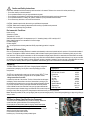
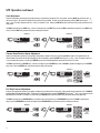
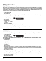
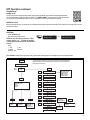
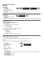
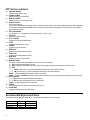
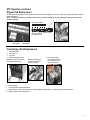
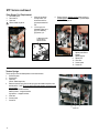
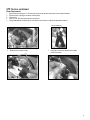
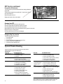
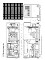
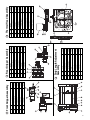
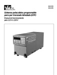
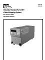
#45-930
#45-935
Shielded Twisted Pair (STP)
Cable Stripping System
For 115V or 230V
Operation Manual
Shielded Twisted Pair (STP) Cable Stripping System
Table of Contents
Introduction .....................................................................
Caution and Safety Instructions .......................................
Environmental Conditions ...............................................
Warranty & Service Policy ...............................................
Unpacking........................................................................
STP Service Setup ...........................................................
Electrical Connection Requirements ...............................
Air Connection Requirements ..........................................
System Controls ..............................................................
Heat Adjustment .........................................................
Thermal Head Rotation Speed Adjustment..................
Pull Grip Pressure Adjustment ...................................
Strip Length Adjustment.............................................
STP Operation
Head Adjustment ........................................................
Thermal head Rotation Speed Adjustment ..................
Pull Grip Pressure Adjustment ...................................
Strip length Adjustment..............................................
Cycle Mode ................................................................
Slug Removal ............................................................
2
3
3
3
3
3
4
4
4
4
5
5
5
6
6
6
7
7
8
Program Mode................................................................. 9
Set Mode .........................................................................10
STP Service .....................................................................11
Batching...........................................................................11
Recommended Spare Parts ..............................................12
Parts Replacement
Gripper Pad Replacement ...........................................13
Front Gripper Pad Replacement..................................13
Rear Gripper Pad Replacement ...................................14
Tension Springs .........................................................14
Blade Replacement ...............................................15-16
CPU Module Replacement..........................................17
Power Module Replacement .......................................17
Maintenance ....................................................................18
Changing Slug Tray Location ..........................................18
Trouble Shooting .............................................................18
Machine Schematic & Parts List ................................19-21
Electrical Schematic.........................................................22
Introduction
The IDEAL Shielded Twisted Pair Cable Stripping System (STP) is a programmable bench top machine that accurately removes the outside jacket from
shielded twisted pair cable. The STP addresses occupational ergonomic needs by offering an alternative to manual stripping methods which are known
to have contributed to cumulative tissue trauma.
The STP system automatically adjusts to the size of the cable being stripped up to a maximum diameter of 0.3125 inches. Cable strip length is
programmable by inches or millimeters. The strip length is adjusted in preset increments from a minimum of 1-1/4 inches to a maximum of
6.00 inches. A strip operation cycle can be completed in as little as five seconds.
The large, easy-to-read display shows the operating function status and facilitates program entry. A memory module stores up to 500 user defined
“batch” programs and incorporates a battery back-up system. A service machine message can be programmed for display when the machine completes
a preset amount of operations. All operating parameters can be secured from unauthorized modifications by a programmable security code. The
intuitive front panel keypad provides tactile feedback and is highly resistant to harsh industrial environments.
The STP stripping system consistently produces quality levels achieved in the aerospace industry. With its wide array of powerful features, the IDEAL
STP is extremely flexible, simple to program and easy to use.
2
Caution and Safety Instructions
Please read, understand and follow the warnings and instructions in this manual. Failure to do so can result in serious personal injury.
• Do not alter, modify or misuse the machine.
• Do not operate the machine using an ungrounded electrical system.
• Do not perform any maintenance on the machine unless both the electrical power and air supply are disconnected.
• Do not operate the machine in a damp, wet, gaseous, hazardous or poorly ventilated work environment.
• Do not obstruct any ventilation or air flow around the machine.
CAUTION – Hazardous parts inside, refer servicing to qualified service personnel.
CAUTION – Blade area can create high temperatures; refer servicing to qualified service personnel.
CAUTION – Use proper heavy lifting procedures.
Environmental Conditions
Indoor use only
Altitude up to 2,000m
Temperature 5°C to 40°C
Maximum relative humidity 80% for temperatures up to 31° decreasing linearly to 50% humidity at 40°C
Mains voltage fluctuations not to exceed±10% of normal voltage
Insulation Category II
Pollution degree 2
Unit can produce sound levels greater than 85 dB, proper hearing protection is required.
Warranty & Service Policy
Each unit is warranted to be free from defects in materials and workmanship under normal use and service for a period of 12 months after the date of
purchase. The obligations of IDEAL under this warranty shall be limited to repairing at the Sycamore, Illinois manufacturing facility any unit which
shall, within the 12 month period, be returned to us with the transportation charges prepaid, and with our examination shall disclosed to our satisfaction to have been defective. This warranty shall not aply to any model which has been altered or repaired outside the factory in any way so as to affect
its operation nor which has been subject to misuse, negligence, accident or installed or operated in any other way than in accordance with our instructions, nor shall this warranty extend to repairs or replacement made necessary by the use of accessories not recommended by IDEAL.
Unpacking
The IDEAL Shielded Twisted Pair (STP) Cable Stripping System is shipped in
protective foam packaging. You may wish to save this packaging for future
transportation.
Description
Cat. No.
STP, 115 VAC, 60 Hz 4A
STP, 230 VAC, 50 Hz 2A
Power Cord
T®-Cutter Lite
Air Hose
Slug Tray
Air Regulator
Operation Manual
Security keys
IDEAL Key Chain
45-930
45-935
K-6773
45-260
K-6865
IA-3124
45-906
ND-3514
1301.012
99-020
The STP unit is equipped with a power cord, air hose, slug tray, IDEAL T®-Cutter
Lite wire cutter, keys, key chain, air regulator kit and an operation manual.
Lifting Instructions for the STP
Locate the front and rear of the machine. The front of the machine has the keypad
and display. Position the machine so the front of the machine is pointing to your
left and the rear of the machine is to your right. Also position the machine as close
to your body as possible. Place your left hand underneath the bottom plate and
center it between the two front rubber feet. Place your right hand underneath the
bottom plate and center it between the two rear rubber feet. Pull the machine up and
toward your body. When carrying the STP, always keep the machine as close to your body as possible.
Note: Where ever possible, lift with your legs slightly bent and your back straight (vertical). Lift the load by straightening your legs not by pulling up
with your arms.
STP Service Setup (Qualified Service Personnel)
The STP front cover is secured with two (2) screws for shipping. Remove the
screws from lower right and left sides of cover before opening lid.
Gripper pad pins are secured with plates for shipping. Remove these plates
from both front and rear gripper pad housings before machine use.
NOTE: Do not invert the unit after shipping plates have been removed. Gripper
retaining pins will fall out when inverted.
Close cover and replace screws removed.
Install slug tray - Insert the long screws provided, tighten.
Rear
Front
3
STP Service Setup Continued
Electrical Connection Requirements
Voltage Selection
The STP operates on either 115V/230V AC; 45-930, 115V AC 4A 60 Hz ; 45-935, 230V AC 2A 50 Hz. Proper voltage will be preset at the factory.
Fuse Replacement
Disconnect power cord and remove the fuse cartridge using a small blade screwdriver or similar tool. Replace two fuses with recommended fuses.
45-930, 4AT 250V, 1/4” x 1-1/4”; 45-935, 2AT 250V, 5 mm x 20 mm, insert the fuse cartridge back into the unit making certain the proper voltage is
selected.
On-Off Switch — Located on the back of the unit, the on/off switch controls the main
electrical power supply.
Air Connection Requirements
Connect 1/4" coiled air hose to the air inlet fitting located on the back of the unit. This is a reusable compression type fitting.
To connect air hose:
1. Disconnect electrical power supply.
2. Connect the air hose by inserting it firmly into compression fitting.
Air must be clean, dry and pressure regulated to 100 PSI.
The STP consumes approximately 50 cubic inches (about .03 cubic feet) of compressed air per cycle. Total air volume consumed depends on frequency
of operation.
To disconnect air hose;
1. Disconnect electrical power supply.
2. Disconnect air supply.
3. Depress the red ring and pull on the air hose.
STP Operating Principles and Terms
The following section describes the basic principles of operation of the 45-930, STP.
The STP uses a combination of four variables to perform each strip. It is important to
understand each of these four control parameters and how they interrelate to obtain
the desired stripping results. The four variables are HEAT, SPEED, PRESSURE
and STRIP LENGTH. Each variable is described in terms of settings, ranges and
effects on stripping. The individual variable settings may affect the other variables
and the final stripping results. Please refer to the “Electrical Controls” section for
instructions on how to regulate each setting via the control panel.
HEA T
SPEED
PRES SURE
STRIP
LENG TH
PRGM.
COUNT
HIGH
CLEAR
BA TCH
ENTER
HEAT: Thermal Blade
The HEAT setting controls the level of power (heat) directed to the blades during the thermal cutting phase of the stripping cycle, with 10% being
lowest heat and 100% highest. The STP may also be operated with a heat setting of 0%, which runs the unit through a complete cycle without using
the blades. This is intended to pull off a slug that has already been cut either by the STP or manual methods.
Since the STP is a thermal stripper, heat plays a very important role in the stripping process. Insulation materials have a wide variety of melting
temperatures, requiring the STP to produce a full range of blade HEAT settings. The melting temperature of an insulation material, high or low, must be
consistently matched by the STP blade heat setting for a successful stripping operation.
Another important factor is the rate at which the blade heat penetrates the insulation material. A tendency may be to strip at the highest blade heat available. This produces two undesirable results. First, the higher blade HEAT setting is inversely proportional to blade life. Second, the blade may
displace the insulation material too quickly, producing an excessive amount of contact with the inner shield. For these reasons it is important to
correlate the blade HEAT setting with the blade rotation SPEED setting.
4
STP Operating Principles and Terms (continued)
SPEED: Thermal Head Rotation
SPEED refers to the rate of rotation by the Thermal Head of the STP. This is the rate at which the blades are rotated about the wire being stripped. The
slowest speed is 1 and 10 the highest.
Running at a faster speed requires a higher blade heat setting which may shorten the blade life. A superior strip quality is obtained at lower blade HEAT
and SPEED settings. However, the various types and thicknesses of insulation material requires a wide variety of HEAT and SPEED setting
combinations (to avoid touching the inner braid).
PRESSURE: Rear Grip Mechanism
The PRESSURE setting regulates the air pressure delivered to the internal, rear grip mechanism. This mechanism is used to pull the stripped slug off
the wire. Based on a line pressure of 100 PSI, which is required for operation of the unit, the internal rear grip can be set to operate from 5 PSI to
100 PSI in increments of 5 PSI. Various insulation materials and shield types require varying grip pressures to obtain optimal slug removal results.
The rest of the machine runs on a constant 100 PSI line pressure.
Having air pressure controlled electronically allows the STP to use a variable amount of grip force to hold the insulation slug while trying to pull off the
slug. This is important for three reasons. First, various materials adhere to the braid differently and require more or less grip pressure to be pulled from
the shield. Excessive grip pressure increases internal friction between the slug and shield, preventing removal of the slug. Second, different materials
have varying coefficients of friction with the grip pads. This creates the need for a wide variety of grip PRESSURE settings. Finally, the strip length
affects the amount of grip pressure required.
STRIP LENGTH
The strip length range of the STP is from 1.25 to 6.00 inches (31 to 150 mm). It can be set in increments of .01 in. or 1 mm. The strip length
required for a given wire is a user-defined variable.
Longer or shorter strip lengths may require varying grip PRESSURE settings. Once the STP is set to strip 3.00 inches or longer the grip PRESSURE
setting remains fairly constant for a given wire type. However, when stripping less than 3.00 inches it may be necessary to increase the grip
PRESSURE setting. This is due to the fact that the internal, rear grip mechanism is about 4.00 inches long and consists of separate pressure points.
When less than 3.00 inches is to be removed, the grip mechanism is not fully utilized and may require a higher PRESSURE setting to accomplish the
task.
Any given wire may be successfully stripped over a range of setting combinations. It is important to look at all of the variables and resulting
performances in order to select the combination that best suits the specific stripping requirements.
IDEAL INDUSTRIES, INC. offers free application assistance... for immediate assistance, call our technical service hotline at 1-800-338-4495.
STP Operation
When the machine is turned on, the software version is briefly displayed followed by
the machine initializing.
Example: Ready Mode Display
Then the Machine Status display appears showing the present settings. During
operation there are three different status displays: READY MODE, “ENTER VALUE”
(a value is being entered or the machine is adjusting to a new value) and “CYCLE IN
PROGRESS” (the machine is in a strip cycle).
At this point, you can proceed stripping wire, enter new values or retrieve a preset batch
with different settings.
Use the following procedures to change the machine settings via the
control panel keeping in mind the “Operating Principles and Terms”
described on page 4, while selecting process variables.
HEA T
SPEED
PRES SURE
STRIP
LENG TH
PRGM.
COUNT
HIGH
CLEAR
BA TCH
ENTER
All control settings can be set by either using the arrow keys or setting
discrete values on numeric key pad.
5
STP Operation continued
Heat Adjustment
Heat can be adjusted by pressing [0] through [9] producing corresponding heat values of 0% through 90%. Pressing HIGH sets the heat at 100%. If
the heat is set at 0%, the machine completes the cycle without using the blades. The heat can also be adjusted by pressing HEAT and using the [ ↑ ]
and [ ] keys. The heat is adjusted from 0% to 100% in increments of 10%. Pressing the ENTER key exits from the heat entry mode and returns to the
ready mode.
↑
If CLEAR is pressed during a HEAT entry, it returns to the beginning of the HEAT entry mode. If CLEAR is pressed at the beginning of the HEAT entry
mode, it exits the HEAT entry mode and the previous settings are returned.
Example 1
HEAT
20%
10
40
3.10
ENTER VALUE
Press
Example 2
ENTER
Press
HEAT Field will Flash
HEAT
20%
10
40
3.10
PRGM.
HIGH
ENTER VALUE
or
Press
Press
Or Press for
100% Heat
HEAT Field will Flash
Press To
Enter Single
Digit Value
BA TC H
ENTER
Thermal Head Rotation Speed Adjustment
Speed can be adjusted by pressing [1] through [9] corresponding to speeds 1 through 9, and pressing HIGH for speed 10.The speed at which the
thermal blades rotate around the wire being stripped can also be adjusted by pressing SPEED and using the [ ↑ ] and [ ] keys. The speed is set from 1
to 10, the fastest setting being 10. Pressing the ENTER key exits from the speed adjustment mode and returns to the run mode.
↑
If CLEAR is pressed during a SPEED entry, it returns to the beginning of the SPEED entry mode. If CLEAR is pressed at the beginning of the SPEED
entry mode, it exits the SPEED entry mode and the previous settings are returned.
Example 1
SPEED
20%
10
40
Example 2
3.10
ENTER
SPEED
20%
10
40
3.10
PRGM.
HIGH
ENTER VA LU E
ENTER VA LU E
Press
Press
or
Press
Press
Or Press for
Speed 10
SPEED Field will Flash
SPEED Field will Flash
Press To
Enter Single
Digit Value
BA TC H
ENTER
Pull Grip Pressure Adjustment
Pressure can be adjusted by pressing the numbers corresponding to pressures 05% through 95%, pressing HIGH sets the pressure at 100%. EXAMPLE:
press [4] then [5] to get pressure at 45%. The pressure can also be adjusted by pressing PRESSURE and using the [ ↑ ] and [ ] keys. Pressure can be
adjusted from 5 to 100 PSI in increments of 5 PSI. Pressing the ENTER key exits from the pressure entry mode and returns to the ready mode.
↑
If CLEAR is pressed during a PRESSURE entry, the display returns to the beginning of the PRESSURE entry mode. If CLEAR is pressed at the
beginning of the PRESSURE entry mode, the display exits the PRESSURE entry mode and the previous settings are returned.
Example 1
PRESSURE
20% 10
40
Example 2
3.10
ENTER VALUE
Press
PRESSURE Field will Flash
ENTER
Press
PRESSURE
20% 10
45
3.10
HIGH
or
Press
Press
Or Press for
100%
Pressure
PRESSURE Field will Flash
Press To
Enter Single
Digit Value
6
PRGM.
ENTER VALUE
BA TC H
ENTER
STP Operation continued
Strip Length Adjustment, by Discrete Value
For Example Enter Value of 75 mm:
METRIC LENGTH MODE (31 mm to 152 mm)
• Press STRIP LENGTH.
• The strip length display will blink.
• Enter the strip length and then press ENTER.
A strip length is automatically entered after a third digit is pressed.
20% 10
STRIP
LENGTH
ENTER
40
0
ENTER
VALUE
Press
Press Numbers
7 Then 5
Digit Will Blink
Press
ENGLISH LENGTH MODE (1-1/4 inches to 6.00 inches)
• Press STRIP LENGTH.
• The first digit will blink. Press the appropriate number key and it will be entered.
• Press the decimal point.
• The tenths digit will blink, press the appropriate number key.
• Next the hundredth position will blink, press the appropriate number key.
• After typing the hundredth position, the new strip length is set.
If at any time during the strip length entry ENTER is pressed, the current strip length will be set. If CLEAR is pressed during a strip length entry, it
returns to the beginning of the strip length entry mode. If CLEAR is pressed at the beginning of the strip length entry mode, it exits the strip length
entry mode and the previous settings are returned.
For Example Enter Value 3.25 Inches:
STRIP
LENGTH
20% 10
ENTER
40
0.00
BATCH
VALUE
Press
20% 10
40
20% 10
3.00
Press 3
Press
3.20
Press 2
Second Digit Will Blink
First Digit Will Blink
40
ENTER VALUE
ENTER VALUE
Press 5
Third Digit Will Blink
Strip Length Adjustment By Increment
While in the ready mode, the strip length can be changed up or down by increments using the [ ↑ ] and [ ] keys. Programming the increment is
explained in the Set section of Program.
↑
In either of the strip length entry methods, the strip length is checked. If the strip length is invalid, an appropriate message appears and the previous
strip length is displayed.
Cycle Mode
NORMAL STRIP CYCLE
• To select a new cycle mode, press Program/High
Press
• Enter in the 3-digit security code
Note: All units are factory preset to a 3-digit security code of “111.” To make any changes in the Program Mode the security
code must be entered.
PRGM.
HIGH
• The display will show
1 - Test
2 - Set
3 - Mode
Clear_Esc
•
•
•
•
•
•
Select [3] for Mode
Select [1] NORMAL CYCLE MODE
Press count/clear on your key pad
Self Check - Press enter and hold to display batch number and selected cycle mode.
Insert wire for normal cycle mode
Remove wire when cycle is completed
7
STP Operation continued
TWO STAGE CYCLE
The TWO STAGE CYCLE is intended to break the STP’s stripping cycle into two separate stages; stage one is for cutting, stage two is removal. When the
cable is inserted, the first stage will thermally cut the insulation. When this stage is completed and the cable is removed, the cable can be inspected for a
complete cut, or the cable can be flexed to insure a complete cut has been achieved. When the cable is re-inserted into the STP, the slug is removed thus
completing stage two. Some insulations will require all material to be separated prior to the removal stage. Between the two stages the display will show
that the cable must be re-inserted to complete the cycle or the cycle may be terminated by pressing clear.
• To select a new cycle mode
Press PROGRAM/HIGH
Enter in the 3-digit security code
Note: All units are factory preset to a 3-digit security code of “111.” To make any changes in the Program Mode the security
code must be entered.
• The display will show
ENTER IN 3-DIGIT
1 - Test
2 - Set
SECURITY CODE
—
3 - Mode
Clear_Esc
Press
• Press [3] for mode
• The display will show
[1] - Normal
[2] - Two Stage
[3] - Double Cut
Select [2] for Two Stage Mode
• Self Check - Press enter and hold to display batch number and selected cycle mode.
• Insert wire into wire port. Note: This stage will cut only the outer insulation.
• Remove cable from unit, inspect and possibly flex to insure all material has been separated to complete the cut.
• Re-insert wire into port to complete second stage. Note: Slug is removed in this stage.
• Remove wire from port.
PRGM.
HIGH
DOUBLE CUT CYCLE
The DOUBLE CUT CYCLE is designed to make two cuts in the jacket and then remove the outer most slug while leaving the inner most slug in place to
protect the braid. The length of the inner slug can be selected. The total of the two slug sections is equal to the overall strip length value.
• To select a new cycle mode
ENTER IN 3-DIGIT
Press PROGRAM/HIGH
SECURITY CODE
—
Press
Enter in the 3-digit security code
Note: All units are factory preset to a 3-digit security code of “111.” To make any changes in the Program Mode the security
code must be entered.
• The display will show
1 - Test
2 - Set
3 - Mode
Clear_Esc
• Press [3] for Mode
• The display will show
[1] - Normal
[2] - Two Stage
[3] - Double Cut
Select [3] for Double Cut
• Set Slug length for Double Cut 0.00 in. - The tenths digit will be blinking, when this value is entered, the hundredths place will blink. After the
hundredths place is entered the value is automatically entered. Due to the nature of the double cut cycle, some combinations of strip lengths and
slug lengths cannot be performed.
• Press Count/Clear on your key pad
• Self Check - Press enter and hold to display batch number and selected cycle mode.
Note: Slug length too long for strip length - This message appears on the screen when the cycle is triggered. The cycle will not run. When the
system receives a trigger, an audible tone will beep and the above message will continue to be displayed on the screen for two seconds. The system
then returns to the ready mode. In order to get a Double Cut cycle to run, one must increase the strip length or decrease the slug length until an
acceptable combination is reached. Min. 1.25 strip length.
• Insert wire for double cut cycle mode
• Remove wire when cycle is complete.
PRGM.
HIGH
8
STP Operation continued
Slug Removal
SINGLE CYCLE
The STP can be used to remove the slug without applying heat to the blades, if the insulation has already been severed.
This is accomplished by pressing “0” when the unit is in the “READY MODE”. The next cycle will run with zero heat and
act only as a slug removal machine. When this cycle is completed, the STP returns to the previous settings.
BATCH
ENTER
REPEATING CYCLE
When the heat value is set to “0” percent the unit will perform the slug removal cycle when activated. The unit remains in this mode until a non zero
heat value is selected.
Set Mode
• Press PROGRAM/HIGH
• Enter in the 3-digit security code
NOTE: All units are factory preset to a 3-digit
security code of “111”. To make any changes
in the Program Mode the security code must be
entered.
• Press
1 - Test
2 - Set
3 - Mode
Clear_Esc
• Select [2] - Set
PRGM.
HIGH
Press
ENTER IN 3-DIGIT
SECURITY CODE
—
PRESS FOR CHOICE
Press
1-TEST 2-SET CLR-ESC
When CLEAR is pressed during any branch of the program mode, the display returns to the beginning and no changes are made.
This flow chart shows the sequence of functions in the program mode indicating the keys to
press and the display screens with available options. The test mode shows the options for
testing sensors and solenoids.
Program
Enter Security Code
Main
Menu
1 Key
1-Test
2-Set
0 Key
0-Test the sensors
Up
Dow n
1 Key
1-Air blast
2 Key
2 Key
1-Set strip length increment
2-Set security code
3-Units
4-Lock out
5-Count
3 Key
1- English
2- Metric
4 Key
1- Lock on
2- Lock off
5 Key
1-Warning on
2-Warning off
3-Set limit
4-Clear count
Up
Dow n
2-Pull cylinder
Up
3 Key
Dow n
3-Chute
4 Key
Dow n Up
4-Trigger
Up
Dow n
5 Key
5-Rear grip
6 Key
Dow n Up
6-Front gri p
7 Key
1-Blade home
2-Grip home sensor
3-Grip back sensor
4-Trigger sensor
5-Wire out sensor
6-Sensor test off
Up
Down
7-Wire gate
Dow n Up
8 Key
8-Blade rotation
9 Key
Dow n Up
9-Strip position
Dow n Up
10-Beeper
1-Full cycle
2-Half cycle
3-Step manually
3 Key
-Counter clockwise
-Clockwise
-Back
-Forward
Dow n Up
11-Blade heat
9
STP Operation continued
Set Mode
1—INCR 2—CODE 3—UNIT
4—LOCK OUT 5—COUNT
1 — STRIP LENGTH INCREMENT
SET STRIPLENGTH
SET STRIPLENGTH
INCREMENT 0.00 IN
INCREMENT
0 MM
This allows programming the strip length in increments by using the arrow keys to increase or decrease the length appearing on the display.
ENGLISH LENGTH MODE - (0.01 in. to 0.99 in.) The tenths position begins blinking. After the tenths digit is entered, the hundredth position blinks.
After the hundredth digit is entered the unit will automatically return to ready mode.
METRIC LENGTH MODE - (1 mm to 99 mm) Enter the increment length, 1mm to 9 mm, and press ENTER. Increment lengths of 10 mm to 99 mm
are automatically entered after being typed in.
2 — SECURITY CODE
ENTER NEW CODE
NEW CODE
=
Enter the new 3-digit code. CLEAR can be pressed any time during this process and the current 3-digit code is restored.
3 — SELECT UNITS (IN/MM)
SELECT
1—ENGLISH 2—METRIC
This allows the selection of English or metric units. Press [1] for English or [2] for metric.
4 — KEYBOARD LOCKOUT
LOCK OUT
1—LOCK ON 2—LOCK OFF
This allows locking out everything on the keyboard except for calling up batches and adjusting the strip length. Press [1] for lock on or [2] for lock off.
5 — COUNTS
There is an 8-digit counter that starts at 0 when the machine is built and counts every cycle. This counter is nonresettable. There is a 6-digit
counter that counts every cycle and is resettable.
[1] (Warning On) activates the “SERVICE MACHINE” warning
1—WARN ON 2—WARN OFF
that appears at the end of a cycle if the resettable count is equal to or
3—SET LIM 4—CLR CNT
above the limit that has been set.
[2] (Warning Off) disables the “SERVICE MACHINE” warning.
[3] (Set Service Limit) allows setting the limit of cycles to when the warning should go off (from 0 to 999999). This also is a reminder to
reset the count.
[4] (Clear Service Count) resets the count.
When the service count is reached a warning is flashed at the end of every cycle if the “warning on” is set.
The counts can be displayed during the ready mode by pressing and holding down COUNT. When the COUNT key is released, the display returns to
the ready to strip mode.
10
STP Operation continued
Batching
Storing a Batch
ENTER IN 3-DIGIT
• Press BATCH
SECURITY CODE
• Press PROGRAM
Press
Press
• Enter the 3-digit security code
• Enter in the batch number for storage
• Press ENTER
All of the current inputs are then stored in this batch. Press CLEAR to exit to the ready mode.
ENTER IN BATCHING
PRGM.
BATCH
HIGH
—
NUMBER
ENTER
0
Press
Retrieving a Batch
ENTER IN BATCHING
• Press BATCH
NUMBER
0
Press
Press
• Enter in the batch number to be retrieved.
• Press ENTER
If the batch number is valid, tehe values of that batch are put in as the new setting and the machine resets itself. Press CLEAR to exit to the ready mode.
BATCH
ENTER
Batch Number Identification
From the ready mode depress and hold down the enter button.
On the top line the batch number will be displayed.
The display will read either:
BATCH #NNN (where NNN = the actual bach number)
or if batch is not currently running:
NO BATCH IS RUNNING
On the second line of the display the type of operating cycle is displayed.
One of the following three cycle types will be displayed.
NORMAL CYCLE
TWO STAGE CYCLE
DOUBLE CUT CYCLE
This status screen will be displayed until the enter button is released.
STP Service (Qualified personnel only)
The quantities listed are replacement parts needed per unit. The quantities needed depend upon machine usage.
Test Mode
This mode is used to test the systems sensor functional components. Each option is explained in next section.
• To select test mode
Press PROGRAM/HIGH
Enter in the 3-digit security code
• Display will show
1 - Test
2 - Set
3 - Mode
Clear_Esc
Press [0] to review the six options
Press [1] for test
Press
USE UP AND DOWN KEYS
or
0—TESTS THE SENSORS
0 — TEST THE SENSORS
This option tests any of the five sensors. Each of six options may be selected in the same manner as before. The six options are listed below.
1 — BLADE HOME SENSOR
(senses if the thermal blades are at home)
2 — GRIP HOME SENSOR
(senses if the pull cylinder is forward)
11
STP Service continued
3 — GRIP BACK SENSOR
(senses if the pull cylinder is back)
4 — TRIGGER SENSOR
(senses if the trigger is being pressed)
5 — WIRE OUT SENSOR
(senses if the wire is out of the insertion hole)
6 — SENSOR TEST OFF
(turns all sensor tests off)
If a sensor test is enabled a tone sounds when the test conditions are present. When a sensor test is enabled all other sensor tests are disabled.
To return back to the test mode, press CLEAR. The sensor test will remain enabled when returning back to the test mode, but will be disabled
once the test mode is exited.
0 — TEST THE SENSORS
A list of options, 0 to 11, will appear on the display by using the [ ↑ ] and [ ] keys.
1 — AIR BLAST
(toggles the air blast on and off)
2 — PULL CYLINDER
(toggles the pull cylinder forward and back)
3 — CHUTE
(toggles the chute opened and closed)
4 — TRIGGER
(toggles the trigger up and down)
5 — REAR GRIP
(toggles the pull clamp opened and closed)
6 — FRONT GRIP
(toggles the front clamp opened and closed)
7 — WIRE GATE
(toggles the entry hole open and closed)
8 — BLADE ROTATION
This routine is used rotate the thermal blades around. This can be done in three ways.
1 — FULL (rotates the thermal blades a full cycle)
2 — HALF (rotates the thermal blades a half cycle around the wire and when the decimal point is pressed it will finish the cycle)
3 — STEP
[ ↑ ] — CCW (by pressing the [ ↑ ] key the thermal blades rotate around in the counter clockwise direction)
[ ] — CW (by pressing the [ ] key the thermal blades rotate around in the clockwise direction)
CLEAR — (the thermal blades are rotated back to home, one level back)
CLEAR — (pressing the CLEAR key a second time brings the thermal blades into a full home position and the program back to the test mode)
9 — STRIP POSITION
[ ↑ ] — BK (moves the set plate toward the back of the machine)
[ ] — FWD (moves the set plate toward the front of the machine)
CLEAR — (brings the program back to the test mode)
10 — BEEPER
(turns the beeper on and off. This will not work with a sensor test on)
11 — BLADE HEAT
(toggles the blade heat to the current heat setting)
↑
↑
↑
↑
Recommended Replacement Parts
The quantities listed are spare parts needed per unit. The quantities needed depend upon machine usage.
Name
Blade Set
Front Grip Pad
Rear Grip Pad
12
Part No.
K-7763
LA2408
LA2414
Quantity Per Unit
1
2
6
STP Operation continued
Gripper Pad Replacement
The STP has two sets of grippers. The front grippers hold the wire while the rear grippers pull off the slug. Both sets of grippers have pads that require
periodic replacement.
NOTE: To replace pads press caps firmly in place, then use a small screwdriver to pop up the tops so they catch on the inner
shoulder of gripper.
REAR GRIP PAD ASSEMBLY
FLAT TABS MUST ALIGN
WITH GRIPPER PIN HOLE.
FRONT GRIPPER
GRIPPER PIN HOLE
REAR GRIPPER
Front Gripper Pad Replacement
1.
2.
3.
4.
Disconnect power
Disconnect air
Open case
Remove screw and top plate
NOTE: Open case by removing screws,
pressing buttons and lifting lid.
6.
7.
8.
9.
NOTE: When closing the lid,
make sure all wires and air
hoses do not interfere.
5. Pull out the 2 gripper
pins. Remove screw and
pull plate and up to the
right to remove plate.
Remove grippers.
Pull off old pads and replace with new set.
Replace grippers. Install left gripper pad on to cylinder adapter and replace grip pin. Locate right gripper and replace grip pin.
Replace top plate, screw and gripper pins.
13
STP Service continued
Rear Gripper Pad Replacement
1.
2.
3.
Disconnect power
Disconnect air
Open case
4.
Caution blades may be hot.
5.
Move pull cylinder all
the way forward. This
allows removal of the
gripper pads toward the
rear.
*Pull out grip pins.
Moveable gripper has 3
grip pins. Stationary
gripper has 1 pin.
6.
Remove grippers. Stationary gripper slides straight out.
Movable gripper must be removed from cylinder adapter
and then slid straight out.
A NEEDLE-NOSE PLIER
MAY BE USED TO
REMOVE THE PINS.
7.
MOVE TO RIGHT, THEN TO REAR
Replace pads. Refer to
diagram.
8. Replace grippers.
9. Replace pins.
10. Close case
11. Connect power
12. Connect air
Tension Springs
Tension springs control the blade pressure on the cable insulation.
1. Disconnect power
2. Disconnect air
3. Open case
Caution: Blades may be hot.
4. Remove one end of spring from current spring post with needle nose pliers to the
desired position. Note: Be sure to rotate thermal head assembly area to adjust both
springs equally.
Low position – extruded insulation
Medium position – wrapped insulation
High position – wrapped insulation
5. Close case
6. Connect power
7. Connect air
Gripper Pins
14
STP Service continued
Blade Replacement
1.
2.
3.
4.
5.
Electronically set strip length to 6". This moves the stop bar all the way back allowing more room to replace the blades.
Disconnect power. (rear gripper will retract all the way back).
Disconnect air.
Open lid. Note: Open lid by pressing button and lifting lid.
Unplug blade electrical connection and cut off connector (a new connector is supplied with replacement blade set).
CUT OFF CONNECTOR
6.
Remove the two hold-down clamps.
7.
Unplug the wire connection between the two blades
(inside silicone tube).
15
STP Service continued
Blade Replacement
9.
Remove the four #4-40
socket head screws
positioning blades.
11. Reverse the process by feeding the new blade wires through the holes and
silicone tubes.
12. Replace the four #4-40 socket head screws for positioning blades.
13. Connect the two short leads inside silicone tube.
14. Pass the two long leads through the long silicone tube and plug into its electrical connection. NOTE: alignment of connector pin.
15. Check blade assembly to make sure it has free blade movement.
16. Close lid making sure all wires and air hoses do not interfere.
17. Connect air and power.
10. Pull elements guiding
lead wire through
holes.
SILICONE TUBE NOT
SHOWN FOR CLARITY.
Blade Set K-7763
Connector
and socket
orientation
Replacement Blade set consists of:
1. Long lead top element
2. Short lead bottom element
3. Long silicone tube
4. Short silicone tube
5. Connector
3 - Long silicone tube
4 - Short silicone tube
5 - Connector
1 - Long lead-top element
2 - Short lead-bottom element
4
Pass tube
over lever
5
3
1
2
Front View
16
Rear View
Place tube
over lever
STP Service continued
CPU Module Replacement
CPU MODULE
The CPU Module (Central Processing Unit) and the Power Module are not field
repairable, they must be returned to IDEAL for service.
The CPU is located behind the faceplate on the inside of front lid.
1. Disconnect power.
2. Disconnect air.
3. Open front lid all the way so that it rests on top of rear cover.
4. Remove the six #8-32 button head screws from faceplate.
POWER MODULE
NOTE: When closing the lid, make sure
all wires and air hoses do not interfere.
5.
Lay module flat and remove the four screws from the
back of the CPU and lift cover off.
7.
Replace cover and return entire module to IDEAL for
service.
Reverse process to replace module.
8.
6.
Disconnect ribbon cable, 2 wire cable and
pull wires out of cover.
TWO WIRE CABLE
RIBBON CABLE
Power Module Replacement
The Power Module is attached to the top of rear cover.
1. Disconnect power.
2. Disconnect air.
3. Remove the five #8-32 button head screws from the rear panel
and remove rear panel.
4. Open lid and support Power Module while removing the four
#6-32 button head screws from top of rear cover.
REMOVE 4 SCREWS
5.
Slide ribbon cable to side and remove module while disconnecting the five plug-in electrical connections
6.
7.
Return entire module to IDEAL for service.
Reverse process to replace module.
17
STP Service continued
Preventative Maintenance
The STP requires very little maintenance aside from changing blades and
gripper pads.
Visually inspect threaded rods and guide rods. If they look dry, lubricate
with a light machine oil.
Remove slug debris from unit.
Replace nylon cable chains (2) as required.
OIL RODS WHEN DRY
Cleaning Your STP
Note: Disconnect power and air when cleaning the unit.
Clean front gripper pads and holder with rubber roller cleaner.
Clean rear gripper pads and holder with rubber roller cleaner.
Remove debrise from both front and the backside of the entry gate with a clean cloth.
Empty the lsug tray in a timely manner.
Clean the outside case of the STP with mild detergent.
Changing Slug Tray Location
The STP slug tray may be repositioned:
1. Disconnect power.
2. Disconnect air.
3. Do not invert machine or gripper pins might fall out.
4. Remove screw, move to opposite side.
5. Secure slug tray by replacing screw.
Tips and Trouble Shooting
Always disconnect power and air when servicing the unit. Please read the
Operation Manual thoroughly before attempting to
operate the STP.
SYMPTOM
RECOMMENDATIONS
• Unit does not turn on. ✔ Check electrical connections.
✔ Check electrical supply.
✔ Check fuses.
• Unit does not cycle.
✔ Make sure unit is in ready mode.
✔ Check air supply and connections.
✔ Make sure cable is making contact with trigger.
• Unit does not strip wire. ✔ Straighten wire to hit trigger.
✔ Check for proper control settings.
✔ Consult IDEAL for wire applications.
✔ Check blade for proper heating.
• Slug does not pull off. ✔ Check for proper PRESSURE setting.
✔ Check air supply. Set at 100 PSI.
✔ Check rear grip for slug debris.
✔ Check rear grip pads. Replace if worn.
✔ Check for proper strip length.
✔ Axial cut of insulation may be required.
Consult IDEAL for wire application support.
18
SYMPTOM
RECOMMENDATIONS
• Wire not cut completely. ✔ Check for proper HEAT setting.
✔ Check for proper SPEED setting.
✔ Check for proper blade movement.
✔ Check condition of blades. Replace if necessary.
✔ Check for proper. blade connections.
✔ Consult IDEAL for wire applications.
• Wire slips further into ✔ Check for proper PRESSURE setting.
machine when gripper ✔ Check front grip pads. Replace if worn.
attempts to pull off
✔ Axial cut of insulation may be required.
slug.
Consult IDEAL for wire application support.
• Unit cycles repeatedly. ✔ Make sure slugs are not in contact with trigger
block.
✔ Check for obstruction at trigger.
✔ Check and empty slug tray.
✔ Make sure slug is not in contact with trigger.
• Wire will not fit into unit. ✔ Straighten excessive curl in wire.
✔ Make sure unit is in ready mode.
✔ Check for obstruction in wire path.
✔ Check all grip pads for proper fit.
All of the cylinders, solenoids and sensors may be tested individually. Please
refer to the TEST section on page 10. Operate each individual component to
determine the status. Repair and or replace components as required.
19
*Refer to Sub Assemblies with their own parts lists on pages 16 and 17.
STP Machine Assembly
Item
1
2
3
4
5
6
7
8
9
10
11
12
13
14
15
16
17
18
19
20
21
22
23
24
Strip
Length
Count
Clear
Pragm.
High
Speed
Heat
Pressure
8
LEN
PSI
SPD
90
Enter
Name
Assy, Control Module
Assy, Front Gripper
Assy, Thermal Head
Assy, Case
Assy, Rear Gripper
Assy, Strip Length Adj.
Assy, Power Module
Cylinder
Coupling, Sleeve
Assy, Stepper Motor
Assy, Top Shelf
Assy, Power Input Module
Fan
Assy, Air Solenoid Valve
Coupling, Hub
Latch
Assy, Heat Transformer
Assy, PC Transformer
Assy, AC Wiring Board
Voltage Bridge Rectifier
Cylinder
Assy, Board Wire Sensor
Switch, Leaf Roller
Slug Tray
HEAT
Qty
1
1
1
1
1
1
1
1
1
1
1
1
1
1
2
2
1
1
1
1
1
1
1
1
•
Batch
Part No.
H-2794
*
*
H-3360
*
*
H-2810
391.09
152.002
K-7794
*
K-8913
742.006
K-7613RP
152.001
1301.012
IA-4918
IA-4917
K-7628
741.047
391.007
LA2702
596.033
IA-4912
5
2
3
20
Item
1
2
3
4
5
Qty
1
1
1
1
1
Name
Assy, Interface Board
Assy, Pressure Regulator
Air Solenoid
Assy, Power Supply
Air Reservoir
Top Shelf Assembly
Part No.
K-7468
K-7749
392.002
IA3273
392.005
1
4
4
1
Qty
6 ft
6 ft
3
1
Item
1
2
3
4
1
1
2
Name
Tubing .250" O.D. (Red)
Tubing .125" O.D. (Red)
Tubing Coiled .125" O.D.
(2 hole) (Black)
Air Hose
Air Tubing
3
K-6865
543.052
Part No.
543.048
543.044
2
2
1
21
10
9
7
Qty
2
1
1
2
1
2
1
2
3
7
11
4
3
6
4
Name
Front Grip Block
Wire Entry Guide
Cylinder Adapter
Spacer, Stop
Sensor Plate
Front Grip Pad
Cylinder
Pin, Gripper
5
1
5
2
6
12
8
8
2
Part No.
LA2381
LA2382
LA2394
LA2397
LA2406
LA2408
391.008
LA2729
Front Gripper Assembly
Item
1
2
3
4
5
6
7
8
2
1
4
Item
1
2
3
4
5
6
7
8
9
10
11
12
6
8
9
2
7
Name
Rear Grip Block
Trigger Block
Cylinder Adapter
Rear Grip Pad
Switch Trigger
Cylinder
Cylinder
Pin, Gripper
Spring Pin
6
4
5
Qty
2
1
1
1
1
2
4
2
2
1
2
2
Name
Rod Support Bar
Cylinder Bar
Stop Bar
Motor Driver Rod
Follower Rod
Rod
Bearing
Fiber Bushing
Sprocket
Cable Chain
Acme Nut
Bumper
Part No.
K-7554
K-7555
K-7556
K-7560
K-7561
K-7562
21.059
24.049
123.049
124.005
379.026
81.017
1
Part No.
LA2388
LA2389
LA2411
LA2414
LA2422
391.007
391.010
LA2729
281.124
Strip Length Adjustment
Assembly
3
Qty
2
1
3
6
1
2
3
4
2
Rear Gripper Assembly
Item
1
2
3
4
5
6
7
8
9
5
6
6
7
13
12
11
10
Item
1
2
3
4
5
6
7
8
9
10
11
12
13
14
3
1
5
Qty
1
2
1
1
3
4
4
4
1
1
1
1
1
2
4 8
3 8
Name
Assy, Blade Set
Element Support Block
Pin, Short
Pin, Long
Wheel, Head
Screw 4-40 X .38 SCHS
Threaded, Standoff
Retaining Ring
Assy, Switch
Assy, Stepper Motor
Sprocket
Cable Chain
Spring, Compression
Spring, Extension
2
Part No.
K-7763
LA2395
LA2402
LA2403
LA2409
113.098
1339.035
482.061
K-7743
K-7794
124.003
123.005
88.005
89.005
Thermal Head Assembly
9
14
22`
5
WIRE ENTRY
GATE SENSOR
CHASSIS GROUND
CONNECTION
120/240 VAC
INPUT
15
1
2
3
H1
1
2
3
27
POWER INPUT
MODULE
17
STRIP LENGTH
STOP
SENSOR
1
4
3
2
14
1
13
25
TRANSPORT
HOME
SENSOR
16
3
1
2
1
2
3
4
H5
1
2
H5
1
2
3
4
H1
BLADE
HOME
SENSOR
AC
WIRING
BOARD
ASSEMBLY
1
2
3
4
11
H2
1
2
3
4
H4
1
2
3
4
H3
8
CPU PCB ASSEMBLY
1
2
3
4
1
2
3
4
1
2
3
4
21
21
1
2
3
4
5
6
7
8
9
10
11
12
13
14
15
16
17
18
19
20
21
22
23
24
25
26
27
28
29
30
31
32
33
34
H4
REAR GRIP
SOLENOID
BLADE TRANSFORMER
-48 VOLT SUPPLY
TRANSFORMER
-5V LOGIC
POWER
SUPPLY
12 3 4 5 6 789
11 1
123 4 56 78 90 12
H1
KEYBOARD
DISPLAY
Electrical Wiring Diagram
-
26
28
1
2
3
4
5
6
7
8
9
10
11
12
13
14
15
16
17
18
19
20
21
22
23
24
25
26
27
28
29
30
31
32
33
34
+
WIRE ENTRY
SOLENOID
9
7
H1
H5
1
2
3
4
5
6
1
2
H6
1
2
3
4
5
6
7
8
9
10
11
12
13
14
15
16
17
18
19
20
21
22
23
24
25
26
27
28
29
30
31
32
33
34
1
2
3
H7
1
2
3
H6
1
2
3
H5
H4
1
2
3
1
2
3
H3
1
2
H11
FRONT
GRIP
SOLENOID
1
2
3
1
2
3
1
2
3
1
2
3
1
2
3
1
2
29
12
1
2
3
4
5
6
1
2
1
2
3
4
5
6
7
8
9
10
11
12
13
14
15
16
17
18
19
20
21
22
23
24
25
26
27
28
29
30
31
32
33
34
10
INTERFACE
BOARD
ASSEMBLY
TRIGGER
SOLENOID
2
H8
1
2
3
1
2
3
1
2
3
4
5
6
7
8
9
10
11
12
13
14
15
16
17
18
19
20
TRANSPORT
SOLENOID
24
H10
1
2
3
H2
H1
1
2
3
1
2
3
4
5
6
7
8
9
10
11
12
13
14
15
16
17
18
19
20
H9
H2
POWER PCB ASSEMBLY
WIRE
SUPPORT
SOLENOID
1111111
6543210987654321
1111111987654321
6543210
+5V LOGIC
POWER
SUPPLY
4
22
1
2
AIR BLAST
SOLENOID
1
2
21
23
12345678911111111112
0123456789 0
11111111112
1234567890123456789 0
1
2
3
4
H7
1
2
3
4
H4
1
2
3
4
H3
1
2
3
4
1
2
3
4
1
2
3
4
AIR OUT
TO REAR
GRIP
SOLENOID
PRESSURE
REGULATOR
ASSEMBLY
ORG
YEL
BRN
RED
AIR
INPUT
THERMAL HEAD
MOTOR
ORG
YEL
BRN
RED
TRANSPORT MOTOR
18
20
19
Item Qty Name
Part No.
Assy, Control
1
1 Module
H-2794
Assy,
H-2810
2
1 Power Module
Assy, AC
3
1 Wiring Board
K-7628
Assy,
4
1 Interface Board
K-7468
Assy, Board
5
1 Wire Sensor
LA2702
6
1 RS-232 Cable
K-7559
Assy, Power
8
1 Supply
IA3273
Assy, PC
9
1 Transformer
IA3275
Assy,
10 1 Alarm-Audio
K-7226
Assy, Heat
11 1 Transformer
IA3276
Voltage Bridge
12 1 Rectifier
741.047
Assy, Wiring
13 1 Power Input
IA3274
Module
Switch,
14 1 Leaf Roller
596.033
Assy, Power
15 1 Input Module
K-8913
16 1 Fan Harness
K-7742
17 1 Fan
742.006
18 1 Assy,
K-7794
Stepper Motor
19 1 Assy,
K-7793
Stepper Motor
Assy, Pressure
20 1 Regulator
K-7749
Assy,
21 1 Flat Cable (20)
K-7759
Assy, Blade
22 1 Harness
K-7744
23 1 Assy, Blade Set
K-7763
Assy, Air
24 1 Solenoid Wiring K-7748
Assy,
25 3 Switch Wiring
K-7743
Assy, Trigger
26 1
K-7747
Harness
Assy, Wire
27 1 Out Harness
K-7746
28 1 Switch Trigger
LA2422
Assy, Heat
29 1 Power Harness
K-7745
Warranty limited solely to repair or replacement; no warranty of merchantability, fitness for a particular purpose or consequential damages.
1000 Park Avenue, Sycamore, IL 60178 – Manufacturing Facility
Form No. ND 3514-1
©2002 IDEAL INDUSTRIES, INC.
IDEAL INDUSTRIES, INC.
Becker Place, Sycamore, IL 60178 – 800-435-0705 in U.S.A.
Ajax, Ontario, L1S 2E1, Canada – 800-527-9105 in Canada
Warrington, Cheshire WA5 5TN, England – 44 1925 444.446
www.idealindustries.com
Rev. 4/02
Printed in U.S.A.