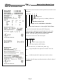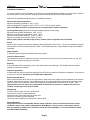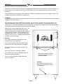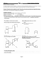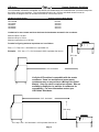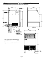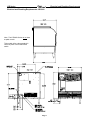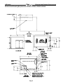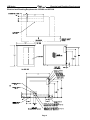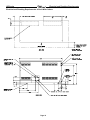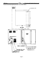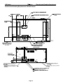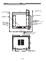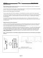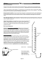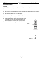
1
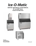
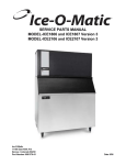
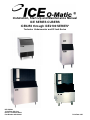
Installation, Start-Up and Maintenance Manual
ICE SERIES CUBERS
ICE0250 through ICE2100 SERIES*
*Includes Undercounter and 22 Inch Series
ICE-O-Matic
11100 East 45th Ave
Denver, Colorado 80239
Part Number 9081264-01
Print Date 3/05
ICE Series
Forward
How To Use This Manual
ICE-O-Matic provides this manual as an aid to the service technician in installation and maintenance of the ICE
Series (electro-mechanical) cube ice machines. Do not attempt to perform installation, start-up or maintenance
unless you have read and fully understand this manual.
If at any time you encounter conditions that are not addressed in this manual, call, E-mail or write the ICE-O-Matic
Service Department:
ICE-O-Matic
11100 E. 45th Ave.
Denver, Co. 80239
Attn: Technical Service Department
E-Mail: [email protected]
Telephone Numbers
800-423-3367
All Departments
888-349-4423
Technical Assistance Only (After Hours Only)
Any Service communication must include:
• Model Number
• Serial number
• A detailed explanation of the problem
Keep this manual for future reference.
The ICE Series Service Parts Manuals are available separately.
ICE-O-Matic icemakers and dispensers are not approved for outdoor installation.
WARNING: Always disconnect electrical power and shut off water supply whenever maintenance or
repairs are performed on the ice machine and related equipment.
CAUTION: Always wear protective eyewear whenever maintenance or repairs are performed on the ice
machine and related equipment
Page i
ICE Series
Table of Contents
Forward
Page i
Table of Contents
Page ii
Freight Claim Procedure
Page iii
Warranty
Page iv
Model Number and Serial Number Format
Page 1
Installation Guidelines
Page 2
Remote Condenser Guidelines
Page 4
Electrical and Plumbing Requirements
Page 6
How the Machine Works
Page 12
Start-Up Procedure
Page 13
General Maintenance
Page15
Cleaning Procedure
Page 16
Cabinet Care
Page 17
Winterizing Procedure
Page 18
Maintenance Record
Page 19
Page ii
ICE Series
Freight Claim Procedure
Freight Claims Important!
Inspect Promptly
This merchandise has been carefully inspected and packed in accordance with the carrier’s packing specifications.
Responsibility for safe delivery has been assumed by the carrier, if loss or damage occurs, you as the consignee must
file a claim with the carrier and hold container for carrier’s inspection.
Visible Loss or Damage
Any external evidence of loss or damage must be fully described and noted on your freight bill or express receipt and
signed by the carrier’s agent. Claim should be filed on a form available from the carrier.
Concealed Loss or Damage
If loss or damage does not appear until merchandise has been unpacked, make a written request for inspection by the
carrier within 15 days of the delivery date. Then file a claim on a form from the carrier.
File Claim Without Delay
Do Not Return Damaged Merchandise to ICE-O-Matic
Page iii
ICE Series
Warranty
ICE-O-MATIC
Parts and Labor
Domestic & International Warranty
Mile High Equipment Company (the “Company”) warrants Ice-O-Matic brand ice machines, ice dispensers, remote condensers, and
ice storage bins to the original user customer against defects in material and factory workmanship for a period of thirty-six(36)
months on cube ice machines and twenty-four (24) months on flake ice machines, “compressed ice” ice machines, ice dispensers,
remote condensers, and ice storage bins from the original date of installation on all parts. The Company will also pay straight time
labor, based upon regional norms, to correct said defects for a period of thirty-six (36) months on cube ice machines and twentyfour (24) months on flake ice machines, “compressed ice” ice machines, ice dispensers, and ice storage bins. An additional twentyfour (24) month warranty on parts (excluding labor) will be extended to all cube ice and flake ice machine compressors and cube ice
machine evaporator plates from the date of original installation. Ice/beverage dispensers will be warranted for twelve (12) months on
parts only. The company will replace F.O.B the Company plant or, R.O.B the Company authorized distributor, without cost to the
Customer, that part of any such machine that becomes defective. In the event that the Warranty Registration Card indicating the
installation date has not been returned to the Company, it shall be assumed the unit was installed three (3) months after the date of
shipment from the factory. Irrespective of the actual installation date, product will be warranted a maximum of seventy-two (72)
months from date of shipment from the Company.
No replacement will be made for any part or assembly which (I) has been subject to an alteration or accident; (II) was used in any
way which, in the Company’s opinion, adversely affects the performance; (III) is from a machine on which the serial number has
been altered or removed; or, (IV) uses any replacement part not purchased from the company. This warranty does not apply to
destruction or damage caused by unauthorized service, using other than Ice-O-Matic authorized replacements, risks of
transportation, damage resulting from adverse environmental or water conditions, accidents, misuse, abuse, improper drainage,
interruption in the electrical or water supply, charges related to the replacement of non-defective parts or components, damage by
fire, flood, or acts of God. This warranty is valid only when installation, service, and preventive maintenance are performed by a
Company-authorized distributor, a Company-authorized service agency, or a Company Regional Manager. The Company reserves
the right to refuse claims made for ice machines or bins used in more than one location. Ice bills, normal maintenance, and cleaning
are not covered.
Limitation of Implied Warranty
This warranty is valid only for products produced and shipped from the Company after September 30, 2002. A product produced or
installed before that date shall be covered by the Limited Warranty in effect at the date of its shipment
The liability of the Company for breach of this warranty shall, in any case, be limited to the cost of a new part to replace any part
which proves to be defective. The Company makes no representations or warranties of any character as to accessories or auxiliary
equipment not manufactured by the Company.
REPAIR OR REPLACEMENT AS PROVIDED UNDER THIS WARRANTY IS THE EXCLUSIVE REMEDY OF THECUSTOMER.
MILE HIGH EQUIPMENT SHALL NOT BE LIABLE FOR ANY INCIDENTAL OR CONSEQUENTIALDAMAGES FOR BREACH OF
ANY EXPRESS OR IMPLIED WARRANTY ON THIS PRODUCT. EXCEPT TO THE EXTENTPROHIBITED BY APPLICABLE LAW,
ANY IMPLIED WARRANTY OR MERCHANTABILITY OR FITNESS FOR APARTICULAR PURPOSE ON THIS PRODUC T IS
LIMITED IN DURATION TO THE LENGTH OF THIS WARRANTY.
Filing a Claim
All claims for reimbursement must be received at the factory within 90 days from date of service to be eligible for credit. All claims
outside this time period will be disallowed. The model, the serial number and, if necessary, proof of installation, must be included in
the claim. Claims for labor to replace defective parts must be included with the part claim to receive consideration. Payment on
claims for labor will be limited to the published labor time allowance hours in effect at the time of repair. The Company may elect to
require the return of components to validate a claim. Any defective part returned must be shipped to the Company, transportation
charges pre-paid, and properly sealed and tagged.
The Company does not assume any responsibility for any expenses incurred in the field incidental to the repair of equipment
covered by this warranty. The decision of the Company with respect to repair or replacement of a part shall be final.
No person is authorized to give any other warranties or to assume any other liability on the Company’s behalf unless done in writing
by an officer of the Company.
Mile High Equipment Company, 11100 East 45th Avenue, Denver, Colorado 80239 (303) 371-3737
September 30, 2002
Page iv
ICE Series
Model and Serial Number Format
Model and Serial Number Format
The serial number format and machine specifics are detailed on the
data plate.
ICE 040 0
H A
2
Design Level
Condenser Type: A=Air, W=Water, R=Remote
Cube Size: H=Half, F=Full
Voltage: 0=115V, 6=230V/60Hz. 5=240V/50Hz.
Approximate Production in 24 hours @70°FAir/50°FWater
Series: Environmental Cuber (Uses HFC Refrigerant)
This format is 14 characters long and begins with a date code
followed by the ICE-O-Matic identifier, and then a sequential
number. This is an entirely numerical serial number.
The serial number will look like the example.
0407 1280 010077
010077 is the serial identifier.
1280 is the identifier. (ICE-O-Matic)
0407 is the date code, in YYMM format. (2004 July)
Large data plate will be placed on the back of the unit.
Small data plate will be placed by the service valves.
The date code will change monthly and yearly to reflect the date of
manufacture.
Page 1
ICE Series
Installation Guidelines
Installation Guidelines
For proper operation of the ICE-O-Matic ice machine, the following installation guidelines must be followed. Failure to
do so may result in loss of production capacity, premature part failures, and may void all warranties.
Reference the installation parameters prior to installing the machine:
Ambient Operating Temperatures
Minimum Operating Temperature: 50°F (10°C)
Maximum Operating Temperature 100°F (38°C), 110°F (43°C) on 50 Hz. Models.
Note: ICE-O-Matic icemakers and dispensers are not approved for outdoor installation.
Incoming Water Supply (See Electrical and Plumbing Diagrams for line sizing)
Minimum incoming water temperature: 40°F (4.5°C)
Maximum incoming water temperature: 100°F (38°C)
Minimum incoming water pressure: 20 psi (1.4 bar)
Maximum incoming water pressure: 60 psi (4.1 bar)
Note: If water pressure exceeds 60 psi (4.1 bar), a water pressure regulator must be installed.
Drains
Route bin drain, purge drain and water condenser drain individually to a floor drain. The use of condensate pumps for
draining water is not recommended by ICE-O-Matic. ICE-O-Matic assumes no responsibility for improperly installed
equipment.
Water Filtration
A water filter system should be installed with the ice machine.
Clearance Requirements
Self contained air cooled ice machines must have a minimum of 6 inches (15cm) of clearance at the rear, top, and
sides of the ice machine for proper air circulation.
Stacking
If the ice machines are to be stacked, refer to the instructions in the stacking kit. ICE-O-Matic does not endorse
stacking air-cooled ice machines.
Dispenser Application
A thermostatic bin control kit should be installed if the ICE Series ice machine is placed on a dispenser. A bin top may
or may not be required. (Exception is the CD400 Series Dispenser)
Electrical Specifications
Refer to the serial plate at the rear of the ice machine to make sure proper voltage and circuit breaker size have been
supplied. Make sure the machine is on a dedicated circuit. European installations require that the electrical supply
fixed wiring must be provided with a disconnect means having a separation of at least 3mm in all poles. The
Undercounter series ice makers are supplied with an electrical cord, all other ice makers will need to be
installed and wired per local electrical codes.
Adjustments
Level the machine within 1/8 inch in all directions.
Check the bin control for proper adjustment.
Check the water in the water trough for proper level.
Check the ice bridge for proper thickness.
Check the water regulating valve adjustment if water cooled.
Remote Machines
Verify the ICE machine is compatible with the remote condenser. Some ice machines and some remote
condensers may or may not have a Mixing Valve (Head Master). Only one valve is required per system.
Kits are available to modify the ice machine or condenser for compatibility. For more information contact
your ICE-O-Matic Distributor.
Page 2
ICE Series
Installation Guidelines
Secure the machine on top of the bin or dispenser.
Attach the ice machine to the bin with the mounting straps provided with the bin or dispenser. If the ice machine is to
be mounted on a bin or dispenser other than an ICE-O-Matic, refer to the manufactures instructions for machine
mounting.
If the ice machine is to be stacked on top of another ice machine, a stacking kit will need to be installed. Refer to the
installation instructions included with the stacking kit.
Important!
A water filtration system should be installed with all ice machines. Check the filter manufactures instructions for proper
installation of the filter system.
All water supply lines must be installed per local codes. Use 1/4 inch O.D. minimum on air cooled machines. On
water cooled machines 3/8 inch O.D. minimum tubing must be run to the condenser. The water supply for the ice
making can “T” off from the condenser line using 1/4 inch O.D. minimum tubing. Make 2 coils of extra tubing so that
the machine can be pulled away from the wall if service is needed.
All drain lines must be installed per local codes. The
purge drain should be a minimum of 5/8 inch O.D.
tubing. Condenser drain on water cooled units should
be 3/8 inch O.D. minimum. Drain line fittings on ICEO-Matic bins are 3/4 FPT. The bin drain should be a
minimum of 3/4 inch O.D. Cold water drains should be
insulated to prevent sweating.
Warning!
Do not apply heat directly to the back of bin as
damage may occur to plastic parts.
Connect power supply to the terminal block in the
control box or at the rear junction box if equipped.
Ensure the machine is level within 1/8 inch in all
directions.
Remove any shipping or packaging material.
If the machine has a remote condenser, reference
Remote Condenser Installation.
Attach the ice machine to the bin
or dispenser with the provided
mounting hardware.
Once the machine has been installed follow the
start-up procedures.
Warning!
Do not apply heat directly to the
back of bin as damage may occur
to plastic parts.
Page 3
ICE Series
Remote Condenser Guidelines
Remote Condenser Installation
For proper operation of the ICE-O-Matic ice machine, the following installation guidelines must be followed. Failure to
do so may result in loss of production capacity, premature part failure, and may void all warranties.
Remote condensers must be installed per local building codes. A two to four inch diameter roof penetration will be
needed for refrigerant lines and electrical conduit. The penetration should be within two feet of where the condenser
will be located. A roof jack must be installed at the penetration.
Installation Guidelines
Ambient operating temperatures: -20°F (-28.9°C) to 120°F (48.9°C)
Maximum refrigerant line length: 60 ft. (18.29 Meters)
Maximum vertical rise:
16 ft. (4.88 Meters)
Minimum condenser height:
ICE Series ice machine remote condensers must not be installed more than 6 feet
(1.3 meters) below the refrigerant line quick connects at the rear of the ice machine. No part of the refrigerant lines,
between the ice machine and the remote condenser, should fall below this point. Condensers must have a
vertical airflow.
Air Flow
Page 4
ICE Series
Remote Condenser Guidelines
The ICE0500R3, ICE0606R3, ICE806R3, ICE1006R3, ICE1606HR3 and ICE1506R2 Remote ice makers incorporate
the mixing valve in the condenser. This configuration allows up to a 100 foot calculated remote line set run.
Reference the diagram below to calculate the maximum 100 foot line set run.
ICE Machine Model Number
ICE1606HR3
ICE1506HR2
ICE1006R3
ICE806R3
ICE0606R3
ICE0500R3
Remote Condenser Model Number
LRC2661
LRC2661
VRC2061
VRC2061
VRC1061
VRC1001
Limitations for new remote machines that have the headmaster mounted in the condenser.
Maximum Rise is 35 feet.
Maximum Drop is 15 feet.
Maximum equivalent run is 100 feet.
Formula for figuring maximum equivalent run is as follows:
Rise x 1.7 + Drop x 6.6 + horizontal run = equivalent run.
Examples:
35 ft. rise x 1.7 + 40 ft. horizontal = 99.5 equivalent feet line run
35 ft. rise
40 ft. horizontal
Verify the ICE machine is compatible with the remote
condenser. Some ice machines and some remote
condensers may or may not have a Mixing Valve (Head
Master). Only one valve is required per system. Kits are
available to modify the ice machine or condenser for
compatibility. For more information contact your
ICE-O-Matic Distributor.
34 ft. horizontal
10 ft. drop
10 ft. drop x 6.6 + 34 ft horizontal = 100 equivalent feet line run
Page 5
ICE Series
Electrical and Plumbing Requirements
Electrical and Plumbing Requirements: ICEU150, 220, 225 and 226
Note: The ICEU150, 220, 225 and 226 do not
have a splash curtain.
These models utilize a thermostatic bin control
in place of a mechanical bin switch.
Page 6
ICE Series
Electrical and Plumbing Requirements
Electrical and Plumbing Requirements: ICEU300
Note: The ICEU300 Series do not have
a splash curtain.
This models utilize a thermostatic bin
control in place of a mechanical bin
switch
Page 7
ICE Series
Electrical and Plumbing Requirements
Electrical and Plumbing Requirements: ICE0250, ICE0400, ICE0500 ICE0600
Page 8
ICE Series
Electrical and Plumbing Requirements
Electrical and Plumbing Requirements: ICE0806 and ICE1006
Page 9
ICE Series
Electrical and Plumbing Requirements
Electrical and Plumbing Requirements: 48 Inch Wide Cubers
Page 10
ICE Series
Electrical and Plumbing Requirements
Electrical and Plumbing Requirements: 22 Inch Wide Cubers
Page 11
ICE Series
Electrical and Plumbing Requirement
Electrical and Plumbing Requirements: ICE1606 Remote
Page 12
ICE Series
Electrical and Plumbing Requirements
Electrical and Plumbing Requirements: ICE1506 Remote
Page 13
ICE Series
How the ICE Machine Works
How the ICE Machine Works
A general description of how the ICE Series cubers work is given below. With the ICE/OFF/WASH switch in the ICE
position, the compressor, water pump and condenser fan motor (when applicable) will energize starting the freeze
cycle.
During the freeze cycle, water is circulated over the evaporator(s) where the ice cubes are formed. When the suction
pressure has pulled down to the proper cut-in pressure of the timer initiate (pressure control), the contacts will close
and energize the time delay module (timer). At this time the cubes will be close to completion.
The remaining portion of the freeze cycle is determined by the timer setting. The timer is pre-set at the factory to
achieve the proper ice bridge thickness but may need to be adjusted upon initial start-up, see Page 15 for timer
adjustment.
Once the amount of time on the timer has passed, the control relay will be energized and the machine will enter
harvest. Power is now supplied to the water purge valve, hot gas valve, and the harvest motor.
The water purge valve opens, and allows the water pump to purge the water remaining in the water trough, removing
impurities and sediment. This allows the machine to produce clear ice cubes and keep mineral build up at a minimum.
The hot gas solenoid opens allowing hot gas to go directly to the evaporator, heating the evaporator and breaking the
bond between the evaporator and the ice slab.
The harvest assist motor, which is also energized during harvest, turns a slip clutch, which pushes a probe against the
back of the ice slab. Once the evaporator has reached approximately 40°F (4.5°F) in temperature, the slip clutch
overcomes the bonding of the ice to the evaporator and pushes the slab of ice off of the evaporator and into the
storage bin.
The clutch also actuates a switch that rides on the outer edge of the clutch. When the clutch completes one
revolution, the switch is tripped and the machine enters the next freeze cycle.
When ice drops into a full bin during harvest, the splash curtain is held open which activates a bin switch shutting the
machine off. When ice is removed from the bin, the splash curtain will close and the machine will come back on.
Note: The ICEU150, 220, 225, 226, ICEU300 and 305 do not have a splash curtain. These models utilize a
thermostatic bin control in place of a mechanical bin switch.
Page 14
ICE Series
Start-Up Procedure
Start-Up Procedure
Before starting the machine, make sure the machine is level within 1/8 inch in all directions, the bin or dispenser leg
height can be adjusted by rotating the leg foot.
Check the water level in the water trough. It should be approximately ½ inch above the top of the water pump impeller
housing. The water level can be adjusted by bending the float arm.
Move the ICE-OFF-WASH switch to the ICE position.
Check for proper water flow over the evaporator(s). There should be an even flow of water over the evaporator(s).
Check the water regulating valve (water cooled machine) for proper adjustment by measuring the water temperature at
the outlet of the condenser. It should be between 100°F and 110°F (38°C and 43°C). Adjust the water regulating
valve as required.
As ice begins to form on the evaporators, check the freeze pattern of the ice. Ice should form evenly across the
evaporator. Models ICE0800, 1000, 1800 and 2100 machines will have a slight variance from the top to the bottom of
the evaporator(s).
Bridge Thickness and Timer Adjustment
Once the ice drops off the evaporator(s) during harvest, check the bridge thickness of the ice slab. The bridge should
be 3/16 of an inch on Undercounter, ICE0250 and ICE0305 units. The bridge should be 1/8 of an inch on all other
units. If the bridge thickness is incorrect, the timer will need adjustment.
The ice bridge thickness is controlled by the freeze timer located in the control box. To check the timer setting add the
seconds of each dipswitch turned to the “ON” position. The number beside the each dipswitch represents seconds.
To increase the bridge thickness, increase the timer setting. To decrease the bridge thickness, decrease the timer
setting. The freeze timer can be adjusted by sliding one or more switches to either the “ON” or “OFF” position to
obtain the desired setting.
Note: The right hand timer on the ICE1400, 1800 and 2100 units should be set at 4 seconds only, do not adjust
this timer.
Bridge Thickness
Combine time in seconds
Timer shown is set for 31 seconds
Page 15
ICE Series
Start-Up Procedure
Bin Control Operation
The bin control is used to shut the machine off when the bin fills with ice. The bin control must be checked upon
installation or initial start-up and when performing maintenance. Adjustments are not covered under warranty.
There is one bin switch for each evaporator. The actuator arm or of the bin switch comes in contact with the splash
curtain. When the bin is full of ice, the splash curtain is held open when ice drops off of the evaporator. This releases
the pressure of the bin switch actuator arm allowing the switch to open.
Single evaporator machines: If the bin switch opens during freeze, or the first part of harvest, relay 2 bypasses the
bin switch and the machine will continue running. If the bin switch is opened during harvest, when the cam switch is
lifted onto the high part of the cam, the machine will shut off. When the bin switch closes again, the machine will
restart.
Dual evaporator machines: If either bin switch opens during the freeze cycle, the machine will shut off. Relay 1 and
relay 2 will bypass the bin switches during defrost. If either bin switch is open when the machine returns to the freeze
cycle, the machine will shut off.
Undercounter machines: A thermostatic bin control is used on the undercounter
models. The bin thermostat is located in the control box with a capillary tube,
which is in a brass thermo-well mounted to the water trough. When ice comes in
contact with the capillary tube thermo-well, the bin thermostat opens and the
machine will shut off.
Bin Control Adjustment
All Models (Except Undercounter Models): Check the bin switch for proper
adjustment by swinging the bottom of the curtain away from the evaporator.
Slowly bring the curtain towards the evaporator. The switch should close when
the bottom edge of the curtain is even with the outer edge of the water trough.
Adjust the switch by loosening the nuts that hold the switch in place. Move the
switch to the proper position and retighten the nuts. Recheck the adjustment.
Adjustments are not covered under warranty.
Undercounter Models
Turn the machine to the ICE or WASH position. Hold ice against the brass
thermal-well mounted to the water trough making sure the ice is in contact with
at least 6 inches (15 cm) of the thermal-well. The machine should shut off in
approximately 1 minute, remove the ice, the machine should restart in
approximately 3 minutes. If a major adjustment is required, turn the adjustment
screw counterclockwise (warmer) until it stops then turn the adjustment screw
clockwise (colder) 1/8 of a turn. This should put the control close to the proper
adjustment, recheck and make a minor adjustment if needed. If a minor
adjustment is required, turn the adjustment screw clockwise (colder) or
counterclockwise (warmer). Adjustments are not covered under warranty.
Splash Curtain
Adjustment Nuts
The bin switch contacts
must be closed when the
bottom edge of the
curtain is flush with the
edge of the water trough
Page 16
Evaporator
ICE Series
General Maintenance
Electrical shock and/or injury from moving parts inside this machine can cause serious injury. Disconnect electrical
supply to machine prior to performing any adjustments or repairs.
Failure to perform the required maintenance at the frequency specified will void warranty coverage in the event of a
related failure. To insure economical, trouble free operation of the machine, the following maintenance is required
every 6 months.
General Maintenance Procedure
To insure economical, trouble free operation of your machine, it is recommended that the following maintenance be
performed every 6 months.
1. Clean the ice-making section per the instructions below. Cleaning should be performed a minimum of every 6
months. Local water conditions may require that cleaning be performed more often.
2. Check ice bridge thickness. See page 15 for proper thickness and adjustment procedure.
3. Check water level in trough. See page 15 for proper water level and adjustment.
4. Clean the condenser (air-cooled machines) to insure unobstructed air flow.
5. Check for leaks of any kind: Water, Refrigerant, Oil, Etc.
6. Check the bin control switch for proper adjustment. See page 16 for bin switch adjustment.
7. Check the water valve (water-cooled machines) for proper adjustment by measuring the water temperature at the
outlet of the condenser. It should be between 100°F and 110°F. (38°C and 43°C)
8. Check all electrical connections.
9. Oil the fan motor if the motor has an oil fitting. (Self contained air-cooled models only)
10. Check the water filter (if applicable) and replace if dirty or restricted.
11. Inspect the evaporator water distribution tube to insure even water distribution of water across the face of the
evaporator.
Page 17
ICE Series
Cleaning Procedure
Ice Machine Cleaning and Sanitizing Instructions
1. Remove the ice machine front panel.
2. Make sure that all the ice is off of the evaporator. If ice is being made, wait for cycle completion, then turn the
machine “OFF” at the ICE/OFF/WASH selector switch.
3. Remove or melt all ice in the storage bin.
4. Add recommended amount of approved nickel safe ice machine cleaner to the water trough according to label
instructions on the container.
5. Initiate the wash cycle at the ICE/OFF/WASH switch by placing the switch in the “WASH” position. Allow the
cleaner to circulate for approximately 15 minutes to remove mineral deposits.
6. Depress the purge switch and hold until the ice machine cleaner has been flushed down the drain and diluted by
fresh incoming water.
7. Terminate the wash cycle at the ICE/OFF/WASH switch by placing the switch in the “OFF” position. Remove the
splash curtain and inspect the evaporator and water spillway to assure all mineral residue has been removed.
8. If necessary, wipe the evaporator, spillway and other water transport surfaces with a clean soft cloth to remove any
remaining residue. If necessary, remove the water distribution tube, disassemble and clean with a bottlebrush.
Reassemble all components and repeat steps 4 through 7 as required to remove residue.
9. Turn OFF ice machine water supply and clean the water trough thoroughly to remove all scale or slime build-up. If
necessary, remove the water trough to reach all splash areas and float.
10. Prepare 1½ to 2 gallons (5.7 to 7.5 liters) of approved (EPA/FDA) sodium hypochloride food equipment sanitizer to
form a solution with 100 to 200 max. ppm free chlorine yield.
11. Add enough sanitizing solution to fill the water trough to overflowing and place the ICE/OFF/WASH switch to the
“WASH” position and allow circulation to occur for 10 minutes and inspect all disassembled fittings for leaks.
During this time, wipe down all other ice machine splash areas, plus the interior surfaces of the bin, deflector and
door with the remaining sanitizing solution. Inspect to insure that all functional parts, fasteners, thermostat bulbs (if
used), etc. are in correct position.
12. Depress the purge switch and hold until sanitizer has been flushed down the drain. Turn ON the ice machine
water supply and continue to purge to the diluted sanitizing solution for another 1 to 2 minutes.
13. Place the ICE/OFF/WASH switch to the “ICE” position and replace the front panel.
14. Discard the first two ice harvests.
Page 18
ICE Series
Cabinet Care
Cleaning stainless steel
Commercial grades of stainless steel are susceptible to rusting if not properly maintained. It is important that you
properly care for the stainless steel surfaces of your ice machine and bin to avoid the possibility of rust or corrosion.
Use the following recommended guidelines for keeping your stainless steel looking like new:
1. Clean the stainless steel thoroughly once a week. Clean frequently to avoid build-up of hard, stubborn stains.
Also, hard water stains left to sit can weaken the steel's corrosion resistance and lead to rust. Use a nonabrasive cloth
or sponge, working with, not across, the grain.
2. Don't use abrasive tools to clean the steel surface. Do not use steel wool, abrasive sponge pads, wire brushes
or scrapers to clean the steel. Such tools can break through the "passivation" layer - the thin layer on the surface of
stainless steel that protects it from corrosion.
3. Don't use cleaners that use chlorine or chlorides. Don't use chlorine bleach or products like Comet to clean the
steel. Chlorides break down the passivation layer and can cause rusting.
4. Rinse with clean water. If chlorinated cleansers are used, you must thoroughly rinse the surface with clean water
and wipe dry immediately.
5. Use the right cleaning agent. The table below lists the recommended cleaning agents for common stainless steel
cleaning problems:
Cleaning Activity
Cleaning Agent
Method of Application
Routine cleaning
Soap, Ammonia, Windex, or
detergent with water.
Fantastik, 409, Spic’nSpan
Liquid are also approve for
Stainless Steel.
Apply with a clean cloth
or sponge. Rinse with
clean water and wipe dry.
Removing grease or
fatty acids
Easy-Off or similar oven
cleaners.
Apply generously, allow
to stand for 15-20 minutes.
Rinse with clean water.
Repeat as required.
Removing hard water spots
and scale.
Vinegar
Swab or wipe with clean cloth.
Rinse with clean water and dry.
Page 19
ICE Series
Winterizing Procedure
Winterizing Procedures
Important!
Whenever the ice machine is taken out of operation during the winter months, the procedure below must be
performed. Failure to do so may cause serious damage and will void all warranties.
1. Turn off water to machine.
2. Make sure all ice is off of the evaporator(s). If ice is being made, initiate harvest or wait for cycle completion.
3. Place the ICE/OFF/WASH switch to the “OFF” position.
4. Disconnect the tubing between the water pump discharge and water distribution tube.
5. Drain the water system completely.
6. On water cooled machines, hold the water regulating valve open by
prying upward on the water valve spring with a screwdriver while
using compressed air to blow all the water out of the condenser.
7. Remove all of the ice in the storage bin and discard.
Page 20
ICE Series
Service History
Service History
Model Number__________________Serial Number__________________Date Installed__________
__________________________________________________________________________________________
__________________________________________________________________________________________
__________________________________________________________________________________________
__________________________________________________________________________________________
__________________________________________________________________________________________
__________________________________________________________________________________________
__________________________________________________________________________________________
__________________________________________________________________________________________
__________________________________________________________________________________________
__________________________________________________________________________________________
__________________________________________________________________________________________
__________________________________________________________________________________________
__________________________________________________________________________________________
__________________________________________________________________________________________
__________________________________________________________________________________________
__________________________________________________________________________________________
__________________________________________________________________________________________
__________________________________________________________________________________________
__________________________________________________________________________________________
__________________________________________________________________________________________
__________________________________________________________________________________________
__________________________________________________________________________________________
__________________________________________________________________________________________
__________________________________________________________________________________________
__________________________________________________________________________________________
__________________________________________________________________________________________
__________________________________________________________________________________________
__________________________________________________________________________________________
__________________________________________________________________________________________
__________________________________________________________________________________________
__________________________________________________________________________________________
__________________________________________________________________________________________
__________________________________________________________________________________________
__________________________________________________________________________________________
__________________________________________________________________________________________
__________________________________________________________________________________________
__________________________________________________________________________________________
__________________________________________________________________________________________
__________________________________________________________________________________________
__________________________________________________________________________________________
__________________________________________________________________________________________
__________________________________________________________________________________________
__________________________________________________________________________________________
__________________________________________________________________________________________
__________________________________________________________________________________________
__________________________________________________________________________________________
__________________________________________________________________________________________
__________________________________________________________________________________________
__________________________________________________________________________________________
__________________________________________________________________________________________
__________________________________________________________________________________________
__________________________________________________________________________________________
Page 21