1
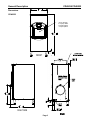
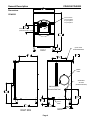
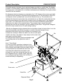
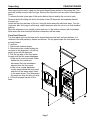
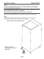
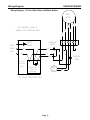
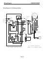
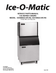
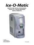
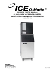
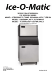
SERVICE/INSTALLATION MANUAL
HOTEL DISPENSER
MODEL CD40030 and CD40022
Ice-O-Matic
11100 East 45th Ave
Denver, Colorado 80239
Part Number 9081317-01
Print Date 10/08
SERVICE PARTS MANUAL
22 INCH WIDE ICE SERIES CUBERS
MODEL-ICE0320, ICE0520
Includes 50Hz. Units
ICE-O-Matic
11100 East 45th Ave
Denver, Colorado 80239
Part Number 9081297-01
PD04/02
Rev1/05
Introduction
CD40030/CD40022
To the owner or user: This product manual is a source of information about the installation,
start up, cleaning, maintenance and repair of the product.
Table of Contents
Introduction
Page 1
General Description and Warranty Information
Page 2
Specification/Limitations
Page 5
Product Description
Page 6
Unpacking
Page 7
Installation-Plumbing
Page 8
Installation-Electrical and Ice Machine Assembly
Page 9
Final Check List/Initial Start Up
Page 10
Dispenser Use
Page 11
General Care and Cleaning
Page 12
Maintenance
Page 14
Adjustments
Page 15
Service Diagnosis
Page 16
Wiring Diagram-115 volt 60Hz. Basic and Water Station
Page 17
Wiring Diagram-Coin Mechanism
Page 18
Wiring Diagram-230 volt, 50HZ basic
Page 19
Ice-O-Matic
11100 E. 45th Ave.
Denver, Co. 80239
800-423-3367
The CD400 Service Parts Manual is available separately, Part Number 9081317-02
Page 1
General Description
CD40030/CD40022
The CD40022 is a 22 inch wide hotel/motel cubed ice dispenser. It is designed to use an
Ice-O-Matic ICE0320 or ICE0520 cube ice machine as the source for ice.
The CD40030* is a 30 inch wide version of the CD40022 and is designed to use Ice-O-Matic
ICE0250 through ICE0500 cubers as its source of ice. Note: 22 inch wide ice machines
are not for use on the 30 inch wide dispensers.
*Higher capacity cubers, ICE0606, ICE0806 and ICE1006 may also be used, but they require
230-volt power.
Ice from the cuber falls into the insulated hopper, where it is stored until needed. When a
user pushes the dispense chute a rotating wheel scoops the ice up to the top front of the
hopper where there is an outlet to the ice chute. Ice is directed into the users container.
Flaked or nugget ice should not be used in these dispensers.
Do not double stack cubers on these dispensers.
Condensate drain pumps are not recommended for drainage.
This is not a waterglass style dispenser.
Basic Specifications
Model
Dimensions
Electrical
Model Description
Bin Storage
WxHxD
Capacity ARI
With 6” Legs
CD40022
22 x 53 x 33½
115/60/1
Basic 22” Model 60 Hz.
120 Lbs.
CD40522
22 x 53 x 33½
230/50/1
Basic 22” Model 50 Hz.
120 Lbs.
Note: The factory installed Water Dispenser and Coin /Token features are not available on the
22-inch wide Basic Push Button dispenser and are not available as a field installed kits.
CD40030
30 x 53 x33½
115/60/1
Basic 30” Model 60 Hz
180 Lbs.
CD40130
30 x 53 x33½
115/60/1
Basic 30” / Water Filler
180 Lbs.
CD40230
30 x 53 x33½
115/60/1
Coin/Token
180 Lbs.
CD40530
30 x 53 x33½
230/50/1
Basic 30” Model 50 Hz.
180 Lbs.
Note: The factory installed Water Dispenser is only available on the 30-inch wide Basic Push
Button dispenser and is not available as a field installed kit. The Coin/Token model is not
available with a Water Filler and is not available as a field installed Water Filler Kit.
Basic models dispense ice when their chute is pushed and will continue to dispense ice until
the chute is released or the bin is emptied. Coin/Token models require a coin or token first.
Tokens are available from Ice-O-Matic, the part number for 500 tokens is TKNS. Water
Dispenser models are basic models with a factory installed separate water dispenser.
Bin Thermostats
Bin Thermostats are not required in ICE series cubers on CD400 Series Dispensers.
Warranty
The CD40030 and CD40022 have a 3 year parts and labor warranty from date of install.
Page 2
General Description
Dimensions
CD40030/CD40022
558.8
22"
CD40022
ICE FILL STATION
8 3/4 [221.5] HIEGHT
13 1/2 [342.9] WIDTH
8 1/2 [215.9] DEPTH
1351.3
53 1/4"
152.4
6"
FRONT
650.6
25 5/8"
850.1
33 1/2"
RIGHT SIDE
Page 3
General Description
Dimensions
CD40030/CD40022
762.4
30"
CD40030
ICE FILL STATION
8 3/4 [221.5] HIEGHT
13 1/2 [342.9] WIDTH
8 1/2 [215.9] DEPTH
254.8
10"
WATER VALVE HEIGHT
(WATER FILLER ONLY - Optional)
1351.3
53 1/4"
152.4
6"
FRONT
609.6
24"
(2) 5/16-18 UNC
ICE HEAD MOUNTING
24.1
1"
451.1
17 3/4"
POWER
CORD
WATER INLET
3/8 FLARE
(WATER FILLER ONLY)
Machine Support
Screwed to Back Panel
650.5
25 5/8"
444.4
17 1/2"
179.1
7"
849.4
33 1/2"
3/4 FPT
DRAIN
189.4
7 1/2"
BACK
RIGHT SIDE
Page 4
189.7
7 1/2"
Specification & Limitations
CD40030/CD40022
This dispenser is designed to be installed and operated indoors, in a controlled
environment. It’s minimum and maximum operating temperature limits are the same as
those for the ice machine.
Minimum
Maximum
100oF
Air Temp
50oF
Water Pressure* 20 psi
60 psi * for water dispenser model
Check the dispenser nameplate, located on the back of the cabinet for specific information.
Ice-O-Matic reserves the right to make design changes and/or improvements at any time.
Specifications and designs are subject to change without notice.
Ice-O-Matic assumes no liability or responsibility of any kind for products manufactured by
Ice-O-Matic that have been altered in any way, including the use of any parts and/or other
components not specifically approved by Ice-O-Matic.
Models
There are three versions of the CD40030 dispensers: Basic, Coin/token and Water
Dispenser. The Basic version is constructed to deliver ice when the ice chute is pushed in,
and it continues to vend ice as long as the ice chute is held in or until the bin is empty.
The Coin/token version is designed to deliver ice after a coin or token is inserted into the coin
slot and then the ice chute is pushed in. Ice vending is limited to a preset time per coin or
token use. Coins or tokens are collected in a coin box at the bottom of the dispenser. A keyed
door allows access to the coin box without removing the front panel.
The Water Dispenser version is a Basic version with a mechanical water faucet added to the
left of the ice chute. Water is dispensed whenever the faucet lever is pushed back. The
CD40030 is available in all versions; the CD40022 is only available as a Basic model.
The Basic models of the CD40022 and CD40030 are available in 230 volt 50 Hz electrical for
those countries with that type of electrical service.
Kits: Bin tops and bin thermostats are not required. No other kits are available.
Warranty If, during the warranty period, customer uses a part for this Ice-O-Matic equipment
other than that an unmodified new part purchased directly from Ice-O-Matic, Ice-O-Matic
Distributors, or any of its authorized service agents and/or the part being used is modified
from its original configuration, this warranty will be void. Further, Ice-O-Matic and its affiliates
will not be liable for any claims, damages or expenses incurred by customer which arises
directly or indirectly, in whole or in part, due to the installation of any modified part and/or part
received from an unauthorized service center. Adjustments are not covered under warranty.
Warranty Procedure If the customer is using a part that results in a voided warranty and an
Ice-O-Matic authorized representative travels to the installation address to perform warranty
service, the service representative will advise customer the warranty is void. Such service
call will be billed to the customer at the authorized service center’s then-applicable time and
material rates.
Page 5
Product Description
CD40030/CD40022
All models consist of a plastic lined, insulated hopper mounted to a metal base. The hopper
contains a 15 blade plastic dispense wheel and a stainless steel sweep arm. The top front of
the hopper has a removable door to facilitate maintenance and cleaning of the hopper without
removal of the ice machine.
The dispense wheel and sweep arm rotate when the ¼ HP dispense drive motor is actuated.
The drive motor’s actuation is controlled by the agitation timer or the vend switch. When the
ice dispense chute is pushed back it moves the actuation lever up. The actuation lever
releases the chute door and pushes the vend switch arm up. When the vend switch arm has
moved a preset distance the vend switch contacts close, providing power to the dispense
drive motor. Ice is delivered to the top end of the ice chute by the dispense wheel and it
slides down the chute to the container below. The container rests on a grill, the grill’s
openings are over the ice catch pan, and any spilled ice goes there. The grill has a flange at
the front to help contain the ice if it spills during vending.
After the ice dispense chute is released, the ice chute door closes to stop ice flow. Ice in the
chute will eventually melt. Melted ice water is routed to the drain through a hose
attached to the bottom of the chute. Spilled ice is contained in an
insulated ice catch pan. Melted ice water from the ice catch pan is
Bin
routed to the drain. User debris is kept away from the drain in the
catch pan by a slotted shield.
The side and front exterior panels are stainless steel.
The vending area and top panel are made of
plastic.
Coin / Token Model
The coin op model’s operation is identical to the
basic operation described above with the exception
that no power is provided to the vend switch until the
coin mechanism has activated the vend timer. The
vend timer then allows the vend switch to be
activated for a set time, during that time the user
must dispense the ice. A green “ready” light over
the vending area will glow when the vend timer is
armed and ready for dispensing.
Chute
Drive motor
Catch Pan
Dispense Wheel
Page 6
Unpacking
CD40030/CD40022
After removing the carton, check for the loose-shipped parts packed in the storage bin. The
parts will include a carton with four legs. Remove the leg carton and any other loose-shipped
items.
To remove the skid, place part of the carton behind the unit and tip the unit on its back.
Remove the bolts holding the skid to the base of the CD dispenser and separate the skid
from the unit.
Install the legs into the base of the unit, using the holes where the skid bolts were. Turn the
leg leveler part of the legs in all the way, adjust them later after the unit is in its final installed
position.
Move the dispenser to an upright position and set it in the location where it will be installed.
Note where the drain lines and electrical connections will be made.
Front Panel Removal
The front panel rests on the base and is located with pins that stick up from the base. It is
retained to the side panels by strikes and latches. The top panel keeps the front panel from
moving forward.
To remove:
1. Disconnect electrical power.
2. Remove the two screws holding the
top panel to the dispenser. Lift the top
panel up and off the dispenser.
3. Pull the top edge of the front panel
forward until the two snaps disengage.
•If the unit is a coin op model, reach
behind the front panel and
disconnect the coin mechanism
harness from the front panel.
•If the unit is a water dispenser
model, reach behind the front panel
and shut off the water supply valve
to the water faucet. Then disconnect
the water line from the shut off valve.
4. Lift the front panel up and off the
base.
Page 7
Installation - Plumbing
CD40030/CD40022
Drain:
All models of the dispenser have a 3/4" FPT drain fitting at the bottom of the back panel.
Connect 3/4" rigid tubing to this connection, a vent is recommended for most installations.
Route the drain tubing to the building drain.
Note: Drain fitting material is plastic. If using copper, sweat the copper tube to copper
fitting together before installing on the dispenser.
Note: Keep PVC solvent away from all plastic parts of the dispenser.
Follow all applicable plumbing codes.
Because the drain tubing will be very cold, insulation is recommenced for the tubing.
Water:
CD40030 water dispenser models must be connected to a source of potable water.
Flush the water supply line before connecting it to the dispenser.
Follow All Local, State and National Codes
Caution: Do not use a
condensate pump in place of
a floor drain.
Page 8
Installation – Continued
CD40030/CD40022
The dispenser is supplied with a power cord. Do not use with an extension cord. The unit
must be plugged into a properly grounded outlet.
The dispenser must be installed so that it is a separate piece of equipment from the ice
machine. The drains and electrical supply must be separate.
Follow All Local, State and National Codes
Ice Machine
All models: Place the dispenser in the location where it will be
used. Level the top edge of the dispenser front to back and left to
right.
Sanitize the dispenser bin with a locally approved sanitizer.
See page 12.
Place the ice machine on the dispenser and secure it to the
dispenser with the hardware and bracket from the dispenser.
Install it according to the instructions in the manual included with
the ice machine.
Caution: Do not use
a condensate pump
in place of a floor
drain.
Route drains separately to a floor drain.
Rear View of Typical Installation
Page 9
Final Check List
CD40030/CD40022
1. Check that electrical power has been supplied.
2. Check that a drain, separate from the ice
machine, insulated and made of rigid tubing,
has been connected to the dispenser.
3. Check that the ice machine has been properly
installed per the ice machines installation
directions. This includes the machine support
included with the dispenser.
4. Check that the ice machine/dispenser
assembly is level front to back and left to right.
5. Check that the coin box access key, if used, is
available.
To Start:
1. Connect electrical power. The dispensing
system will cycle on for a few seconds.
2. Go thru ice machine start up procedures.
Let the ice machine make two harvests.
3. Push the ice chute in.
4. Dispense wheel turns.
5. Ice will be dispensed from ice chute.
6. Fill out the warranty registration form and place
it in the mail.
7. Give the operator any keys and the instructions
on the operation and maintenance of the
product.
Check that the operator knows who to call for
service, and has the product/service manuals for the
machines.
Electrical Sequence
Pushing the ice chute closes a contact to the
gear motor.
The gearmotor will have power and the dispenser will
continue to operate as long as the ice chute is pushed
in. This model also has an agitation cycle of 3
seconds every 6 hours. Since the ice chute is not
pushed in during agitation no ice is dispensed.
Page 10
Dispenser Use
CD40030/CD40022
Basic Model
After the ice machine has operated for a few hours, the CD dispenser can be used. Pushing
the ice chute back will activate the dispense mechanism and ice will drop out of the chute into
the user’s container.
Coin/Token Model Operation
Without activation the dispenser
will not dispense ice when the ice
chute is depressed.
To activate the dispense system,
the user must insert a quarter or a
token in the coin mechanism. If the
quarter or token is accepted, the
Ready Light above the ice chute
glows green, indicating that ice can
now be dispensed. The dispense
system will allow ice vending for a
pre-set time. Once activated,
pushing the chute in (like the basic
model) causes the ice to vend. At
the end of the pre-set time vending
stops.
Free Vend: There is a free vend
switch inside the unit, switch it to
ON to bypass the coin mechanism
and vend ice anytime the chute is
pushed back.
When switched to Free Vend the
Ready light will be ON.
When switching from Free Vend to
Coin / Token operation the Ready
light will be ON for a few seconds.
Water Dispenser Model
In addition to dispensing ice like
the Basic model, the water
dispenser model has a water faucet
located to the left of the ice chute.
The water’s temperature is not
affected by the dispenser. Pushing
in on the faucet lever opens the valve
and water flows out into the users container.
Page 11
General Care and Cleaning
CD40030/CD40022
Periodically inspect and clean the ice dispenser to keep it operating at peak performance.
Wash the outside of the dispenser with warm water and soap. Rinse off and wipe dry.
Cleaning and Sanitizing of the Ice Storage Bin:
The minerals, chlorine and other impurities in the water are rejected from the water during the
freeze cycle of the ice machine. These minerals will collect in the storage bin. The ice storage
bin should be cleaned and sanitized every 90 days.
1. Remove all of the ice stored inside the dispenser bin and shut off the ice maker.
2. Disconnect electrical power to the dispenser.
3. Remove top front panel (in front of ice machine).
Access Door
4. Remove the front panel.
5. Remove the deflector (30 inch wide
only).
6. Lift up and remove the access door at
the front of the bin
7. Reach into the opening, locate the hair
pin and pull it out of the drive shaft.
(Ref. Page 13)
8. Pull the sweep arm off the drive shaft
and remove it from the dispenser.
9. Pull the dispense wheel off the drive
shaft and remove it from the dispenser.
10. Mix a solution of 5 ounces of ice
machine cleaner to 1 gallon of warm
(95oF-115oF) water. Wash the entire bin
area and the delivery area. Use a clean
brush or cloth.
Page 12
General Care and Cleaning
CD40030/CD40022
10. Rinse all areas washed with clean, fresh water
11. Using the ice machine cleaning solution, clean the ice grill, sink, sweep arm and dispense
wheel. Rinse these parts with clean fresh water.
12. To sanitize: Use a locally approved sanitizer per label instruction. Wash all interior
surfaces, the sweep arm and dispense wheel with the sanitizer solution. Use a clean
cloth.
13. Allow the parts to air dry.
Hair Pin
14. Reassemble wheel and sweep arm onto
drive shaft. Be sure to reinsert hairpin.
15. Replace all panels.
16. Reconnect power, be sure ice machine is
switched back on.
Dispense Wheel
Page 13
Maintenance
CD40030/CD40022
Spilled ice and user debris will collect in the ice catch pan, located just below the sink grill.
Occasionally the debris will need to be removed and the drain flushed out to prevent water
back ups.
Note: Failure to clean out the ice catch pan will likely result in a water leak, one that is NOT
covered by warranty.
To clean out the ice catch pan:
1. Disconnect electrical power.
2. Remove the two screws holding the top panel to the
dispenser. Lift the top panel up and off the dispenser.
3. Pull the top edge of the front panel forward until
the two snaps disengage.
If the unit is a coin op model, reach
behind the front panel and disconnect the
coin mechanism harness from the front
panel.
If the unit is a water dispenser model,
reach behind the front panel and shut off
the water supply valve to the water faucet.
Then disconnect the water line from the
shut off valve.
4. Remove the front panel.
5. Pull the ice catch pan forward a few
inches until the drain hose can be
reached.
6. Pull the drain hose from the ice catch pan.
7. Slide the ice catch pan out of the ice
dispenser and clear it of any debris. Wash
out the drain.
8. Return the ice catch pan to its normal
position.
9. Re-attach the drain hose.
10. Reassemble and connect
power.
Page 14
Adjustments
CD40030/CD40022
The dispenser is preset at the factory. Adjustments are rarely needed.
Agitation Time Recommandations:
The standard time is 3 seconds on every
6 hours. Adjust to agitate more frequently
if the unit is installed in a low
temperature environment. However, if
the ice being dispensed is in small
crushed pieces, adjust to agitate less
frequently.
Coin or Token Operation
The standard time for vending is pre set at
20 seconds on the Vend Ready Timer.
This includes time allowed for vending and
customer activation. If necessary, adjust
this timer to a higher number to deliver
more ice, or a smaller number for less ice.
Water Filler
The water faucet can be adjusted for
flow. There is a screw adjustment in the
top of the valve body. Loosen the
locknut and rotate the screw CW for less
water flow. Be sure to re-tighten the
lock-nut or a water leak may develop.
Page 15
Service Diagnosis
CD40030/CD40022
Symptom
Probable Cause
Possible Fix
No ice is dispensed
Basic Model
No power to dispenser.
Check for proper power.
Is dispenser plugged in?
No ice.
Check ice machine.
Vend switch does not close.
Check vend switch.
Check chute for proper motion.
Interlock switch open.
Check interlock switch, be sure
top panel is in place.
Drive motor windings open.
Check drive motor.
Drive gears failed.
Check gear reducer.
Same as above plus coin
switch does not close
Check coin switch.
Vend timer does not work.
Connect power to post 6 of
coin mech timer, timer should
activate, ready light should be
ON and pushing the chute
should start the gear motor,
If not replace the vend timer.
Only dispenser small
amounts of ice.
Sweep arm damaged.
Check/replace sweep arm.
No water dispensed,
Water Dispenser model
Water shut off.
Check water supply to unit,
check shutoff valve inside
cabinet.
Water leak
Drain is plugged
Check drain for restriction
Ice catch pan has overfilled
Remove excess ice.
No ice is dispensed
Coin Op Model
Ice catch pan screened plugged Clean screen
Water drip from spout
Seal between ice machine
And dispenser leaking
Remove ice machine and
replace gasket tape.
Some dripping is normal,
but if severe:
Check spout drain for
restriction.
Page 16
Wiring Diagram
CD40030/CD40022
Wiring Diagram, 115 volt, 60Hz. Basic and Water Station
17-2956-01
GEAR
MOTOR
W O
BN
ALL CONTROLS SHOWN IN
NORMAL ICE DISPENSING MODE
R
BK
BU
6
BK
BK
W W
NO
COM
BU
3
2
3
2
1
INTERLOCK
SWITCH
1
RUN
CAP
6 HOURS OFF
3 SEC. ON
ADJUSTABLE
USE COPPER CONDUCTORS ONLY
Page 17
O
R
W
W
OFF CYCLE
AGITATION
TIMER
4
DISPENSING
SWITCH
EARTH
GROUND
INLET
POWER
CORD
5
BN
Wiring Diagram
CD40030/CD40022
Wiring Diagram for Coin Mechanism Model
17-2967-01
FREE VEND
SWITCH
INLET
POWER
CORD
DISPENSING
SWITCH
R/W
EARTH
GROUND
GEAR
MOTOR
COM
BK
BK
R
BK
R
W
W
W O
BN
NO
BU
BU
3
1
2
W/BU
4
2
3
1
O
COIN MECH.
INDICATOR
LIGHT
R/W
ADJ. COIN
MECHANISM
TIMER
5
W W
OFF CYCLE AGITATION
TIMER: 3 SEC. ON
6 HRS. OFF (ADJ.)
BK
6
(2) 15K OHM
2 WATT
RESISTOR
Y
INTERLOCK
SWITCH
BK/W
6
W/BU
1
2
COIN MECH.
SWITCH
3
BN
RUN
CAP
O
USE COPPER CONDUCTORS ONLY
Page 18
ALL CONTROLS SHOWN IN
NORMAL ICE DISPENSING MODE
Wiring Diagram
CD40030/CD40022
Wiring Diagram 230 volt, 50 Hz. Basic
17-2987-01
GEAR
MOTOR
O
BU
R
BK
ALL CONTROLS SHOWN IN
NORMAL ICE DISPENSING MODE
W
BN
DISPENSING
SWITCH
EARTH
GROUND
INLET
POWER
CORD
BK
BN
R
3
2
1
RUN
CAP
6 HOURS OFF
3 SEC. ON
ADJUSTABLE
O
INTERLOCK
SWITCH
BK/W
BU
BU
OFF CYCLE
AGITATION
TIMER
NO
COM
USE COPPER CONDUCTORS ONLY
Page 19
BK
BN