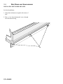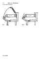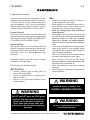
1
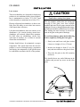
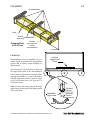
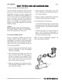
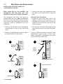
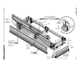
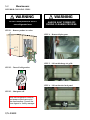
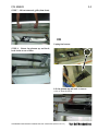
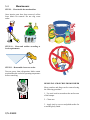
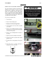
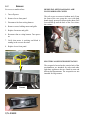
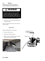
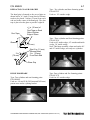
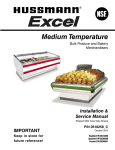
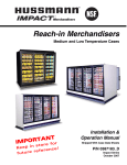
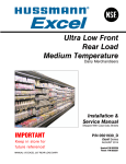
Merchandisers
Euro Deli
Service Merchandisers
Delicatessen Merchandisers
(Includes Wedge Installation)
e
nc
!
T e re
N re f
A
e
Installation &
RTutur
f
Operation Manual
PO
r
o
Shipped With Case Data Sheets
IM re f
e
Ke
p
in
st
o
P/N 406928.
Impact Series
April 2001
P/N 406928
iii
TABLE OF CONTENTS
INSTALLATION
Location . . . . . . . . . . . . . . . . . . . . . . . . . . 1-1
Front Glass Caution . . . . . . . . . . . . . . . . . 1-1
Shipping Damage . . . . . . . . . . . . . . . . . . . 1-2
Exterior Loading . . . . . . . . . . . . . . . . . . . . 1-2
Merchandisers Shipped with End Installed 1-2
Shipping Braces . . . . . . . . . . . . . . . . . . . . 1-2
Shipping Rider . . . . . . . . . . . . . . . . . . . . . 1-2
Leveling . . . . . . . . . . . . . . . . . . . . . . . . . . 1-3
Joining Instructions . . . . . . . . . . . . . . . . . . 1-4
REFRIGERATION / ELECTRICAL
Refrigerant . . . . . . . . . . . . . . . . . . . . . . . . 2-1
Refrigerant Piping . . . . . . . . . . . . . . . . . . . 2-1
Insulation . . . . . . . . . . . . . . . . . . . . . . . . . 2-2
Suction Line . . . . . . . . . . . . . . . . . . . . . . . 2-2
Liquid Line . . . . . . . . . . . . . . . . . . . . . . . . 2-2
Control Settings . . . . . . . . . . . . . . . . . . . . 2-3
Refrigeration Thermostat . . . . . . . . . . . . . . 2-3
Defrost Termination Thermostat . . . . . . . . 2-3
Merchandiser Electrical Data . . . . . . . . . . 2-4
Electrical Connections . . . . . . . . . . . . . . . . 2-4
Field Wiring . . . . . . . . . . . . . . . . . . . . . . . 2-4
Identification of Wiring . . . . . . . . . . . . . . . 2-4
DRIP PIPING AND SPLASHGUARDS
Waste Outlet and Water Seal . . . . . . . . . . . 3-1
Installing Drip Piping . . . . . . . . . . . . . . . . 3-1
Installing Splashguard and
Lower Front Panel . . . . . . . . . . . . . . . . . 3-2
Installing Bottom Rear Panel . . . . . . . . . . . 3-4
START UP / OPERATION
Start Up . . . . . . . . . . . . . . . . . . . . . . . . . . 4-1
Stocking . . . . . . . . . . . . . . . . . . . . . . . . . . 4-1
Load Limits . . . . . . . . . . . . . . . . . . . . . . . 4-1
Load Limit Profiles . . . . . . . . . . . . . . . . . . 4-2
MAINTENANCE
Care and Cleaning . . . . . . . . . . . . . . . . . . . 5-1
Interior Cleaning Steps . . . . . . . . . . . . . . . 5-2
Removable Parts . . . . . . . . . . . . . . . . . . . 5-3
Fan Plenum . . . . . . . . . . . . . . . . . . . . . . 5-3
Cleaning . . . . . . . . . . . . . . . . . . . . . . . . . 5-4
Removing Scratches from Bumper . . . . . . 5-4
SERVICE
Replacing Fan Motors and Blades . . . . . . . 6-1
Removing Polycarbonate Lamp Covers . . . 6-2
Electrical Service Receptacles . . . . . . . . . . 6-2
Replacing Fluorescent Lamps . . . . . . . . . . 6-3
Replacing Lamp Holders and End Caps . . 6-3
Replacing Electronic Ballast . . . . . . . . . . . 6-4
Replacing Cylinders —
Single Pane Glass . . . . . . . . . . . . . . . . . . 6-5
Replacing Single Pane Front Glass . . . . . . 6-6
Replacing Glass Hand Grip . . . . . . . . . . . . 6-7
Hinge Hardware . . . . . . . . . . . . . . . . . . . . 6-7
Repairing Aluminum Coils . . . . . . . . . . . . 6-8
WARRANTY
GARANTIA
IMPORTANT
KEEP IN STORE FOR FUTURE REFERENCE
Quality that sets industry standards.
This merchandiser conforms to the
Commercial Refrigerator Manufacturers Association
Health and Sanitation Standard
CRS-S1-96.
®
12999 St. Charles Rock Road • Bridgeton, MO 63044 U.S.A. • (314) 291-2000 • FAX (314) 298-4767
P/N 406928
1-1
INSTALLATION
LOCATION
!
These merchandisers are designed for displaying
products in air conditioned stores where temperature is maintained at or below 75°F (24°C) and
relative humidity is maintained at or below 55%.
Placing refrigerated merchandisers in direct sunlight, near hot tables or near other heat sources
could impair their efficiency.
Like other merchandisers, these are sensitive to air
disturbances. Air currents passing around merchandisers will seriously impair their operation.
Do NOT allow air conditioning, electric fans,
open doors or windows, etc. to create air currents
around the merchandisers.
Product should always be maintained at proper
temperature. This means that from the time the
product is received, through storage, preparation
and display, the temperature of the product must
be controlled to maximize the life of the product.
CAUTION
Read before raising front glass.
The top cylinders, which allow the raising and
lowering of this glass, have been carefully
installed and tested for the proper tension before
shipment. However, during shipment and storage,
the lubricant inside the cylinders may have settled.
This settling can cause excessive or uneven tension on the glass to the point of breakage.
To avoid any damage, please do the following
before completely raising the front glass.
1. Slowly raise and lower each glass section
6 times to a height of 6 in. (152 mm).
2. Increase the height to about 12 in. (305
mm) and raise and lower the glass 6 times.
3. Then raise the glass to the full extension
and lower.
This should release any settled lubricant in the
cylinders and prevent any stress on the front
glass.
6 in.
(152 mm)
HUSSMANN CORPORATION • BRIDGETON, MO 63044-2483 (Printed in U.S.A.)
Euro Deli Merchandisers
1-2
INSTALLATION
!
WARNING
Do NOT remove shipping braces until
the merchandisers are
positioned for installation.
SHIPPING DAMAGE
All equipment should be thoroughly examined for
shipping damage before and during unloading.
This equipment has been carefully inspected at
our factory. Any claim for loss or damage must be
made to the carrier. The carrier will provide any
necessary inspection reports and/or claim forms.
Apparent Loss Or Damage
If there is an obvious loss or damage, it must be
noted on the freight bill or express receipt and
signed by the carrier’s agent; otherwise, carrier
may refuse claim.
Concealed Loss Or Damage
When loss or damage is not apparent until after
equipment is uncrated, retain all packing materials
and submit a written request to the carrier for
inspection, within 15 days.
!
CAUTION
Do not walk or put heavy objects on case.
EXTERIOR LOADING
Do NOT walk on top of merchandisers or
damage to the merchandisers and serious personal
injury could occur. Merchandisers ARE NOT
STRUCTURALLY DESIGNED TO SUPPORT EXCESSIVE
EXTERNAL LOADING such as the weight of a
person. Do not place heavy objects on the case.
P/N 406928
MERCHANDISERS SHIPPED
WITH END INSTALLED
If the case was shipped with the end installed, two
long bolts were used to hold the shipping brace to
the end. If the shipping bolts are reinserted after
removing the brace, they will extend into the
product area. Therefore, be sure to replace these
bolts with the shorter bolts provided. Refer to the
detailed information provided in the separate
End Kit Instruction shipped with each end.
Note: Be careful not to damage the factory
installed end while moving the case. Make sure
that tools are positioned past the end and beneath
the merchandiser’s support bar.
SHIPPING BRACES
Move the fixture as close as possible to its permanent location and then remove all packaging and
shipping braces. Check for damage before discarding packaging. Remove all separately packed
accessories such as kits, and shelves.
Remove all nut retainers used with shipping
braces.
SHIPPING RIDER
Each case is shipped on a rider to protect factoryinstalled legs, and to make positioning the case
easier. Remove the rider after the case has been
positioned.
Note: Once the rider is removed, the case must
be lifted –NOT PUSHED– to reposition.
To remove the rider, remove screws attaching
each leg to rider. Remove screws holding rider
cross-members, then slide cross-members out
from between sides. Once cross-members are out,
slide the sides out.
P/N 406928
1-3
Cross-Members
Sides
Screws
(each leg)
Shipping Rider
for 8 ft Case
Screws
(two each end
of each
cross-member)
Leg
U
LEVELING
Merchandisers must be installed level to
ensure proper operation of the refrigeration
system and to ensure proper drainage of
defrost water.
Level on
Upper Front
Panel
Set a long level (4 ft [1220 mm] or more) on
the upper front panel of the merchandiser.
Use an open-end wrench to turn leg levelers
until the merchandiser is level from end to
end and from front to back. Check all 6 legs
on 8 ft (2438 mm) cases, or 8 legs on 12 ft
(3658 mm) cases.
Note: To avoid removing concrete flooring,
begin lineup leveling from the highest point
of the store floor.
MINIMUM
HEIGHT
Adjustable
Leg Leveler
Raise
HUSSMANN CORPORATION • BRIDGETON, MO 63044-2483 (Printed in U.S.A.)
MAXIMUM
HEIGHT
Lower
Euro Deli Merchandisers
1-4
INSTALLATION
JOINING INSTRUCTIONS
Sectional construction means that two or more
merchandisers may be joined in line yielding one
long continuous display requiring only one pair
of ends.
All joints must be air-tight to prevent formation
of ice or condensation.
Refer to the detailed information provided in the
separate Joining Instruction shipped with each
case.
P/N 420057
P/N 406928
2-1
REFRIGERATION / ELECTRICAL
REFRIGERANT
The correct type of refrigerant will be stamped on
each merchandiser’s serial plate. The case refrigeration piping is factory sealed, pressurized and
leak tested. Before making refrigeration hookups,
depress universal line valve to ensure that coils
have maintained pressure during shipment.
!
Display Pan
WARNING
Fan
Refrigeration lines are under pressure
and should be depressurized before
attempting to make any connections.
Coil
Piping Location
REFRIGERANT PIPING
Connection Location
The refrigerant line connections are at the righthand end of the merchandiser (as viewed from the
front) beneath the display pans. A sticker marks
the location of the connection “pod.” The installer
must saw a hole through the pod to exit the case.
After connections have been made, seal this outlet
thoroughly. Seal both the inside and the outside.
We recommend using an expanding polyurethane
foam insulation.
Multiplexing
Piping of merchandisers operating on the same
refrigeration system may be run from merchandiser to merchandiser. DO NOT RUN REFRIGERANT
LINES THROUGH MERCHANDISERS THAT ARE NOT
ON THE SAME REFRIGERATION SYSTEM BRANCH as
this may result in poor refrigeration control and
compressor failure.
Interconnecting piping inside the merchandiser
must be located as shown below to allow room for
lifting the hinged fan plenums and for clearance
beneath the display pans. The interconnecting
piping may be run outside the case.
Line Sizing
Refrigerant lines should be sized as shown on the
refrigeration legend that is furnished for the store
or according to ASHRAE guidelines. Refer to the
information on the next page for branch line
piping of Hussmann Equipment.
Oil Traps
P-traps (oil traps) must be installed at the base of
all suction line vertical risers.
Pressure Drop
Pressure drop can rob the system of capacity. To
keep the pressure drop to a minimum, keep the
refrigerant line run as short as possible using a
minimum number of elbows. Where elbows are
required, USE LONG RADIUS ELBOWS ONLY.
!
CAUTION
When brazing pipes be sure to use the
insulation blanket shipped with the
merchandiser to prevent damage to the
plastic case bottom.
HUSSMANN CORPORATION • BRIDGETON, MO 63044-2483 (Printed in U.S.A.)
Euro Deli Merchandisers
2-2
REFRIGERATION / ELECTRICAL
INSULATION
LIQUID LINE
The suction and liquid lines should be clamped or
taped together and insulated for a minimum of
30 ft (9144 mm) from the merchandiser.
Additional insulation for the balance of the liquid
and suction lines is recommended wherever
condensation drippage is objectionable or lines
are exposed to ambient conditions.
•
May be reduced by one size after one half the
case run load. Do not reduce below the case
liquid line connection size.
•
Take-offs to case liquid lines should exit the
bottom of the branch liquid line. Provide an
expansion loop for each evaporator take-off.
(Minimum 3 in. [76 mm] loop.)
SUCTION LINE
•
Pitch in direction of flow.
•
May be reduced by one size at one third of
case run load and again after the second third.
Do not reduce below the case suction line
size.
Minimum Loop
3-in. (76 mm)
Liquid Line Take Off
•
Case suction lines should enter at the top of
the branch line.
Suction Line Return
Offtime Defrost
8 Ft Case
(2438 mm)
12 Ft Case
(3658 mm)
8 Ft Case
(2438 mm)
12 Ft Case
(3658 mm)
Liquid Line
Suction Line
P/N 406928
P/N 406928
2-3
CONTROL SETTINGS
REFRIGERATION THERMOSTAT
Merchandiser data sheets are shipped with this
manual. The data sheets provide case control
settings and defrost data.
The bulb for the optional refrigeration thermostat
is located in the discharge air of the evaporator.
The optional refrigeration thermostat is located
behind the exterior rear panel.
An evaporator pressure regulator or EPR
(primary control) and a 3 – 5ºF (1.7 – 2.7ºC)
differential thermostat (secondary control) must
control refrigeration temperature. The EPR must
be set to maintain the proper saturated evaporator
temperature as listed in the data sheets. The
thermostat must be set a couple degrees colder
than the discharge air temperature specified in the
data sheets. The thermostat will prevent product
freezing should the EPR temperature drift downward during reduced load periods (lights off,
lower ambient). The thermostat will be wired to
control the compressor motor contactor (single
compressor) or a liquid line solenoid valve
(parallel compressor systems).
DEFROST TERMINATION THERMOSTAT
The standard disc type defrost termination
thermostat is not adjustable. This thermostat
is clamped to the inlet of the coil on the lefthand (facing front) end of the merchandiser.
Defrost is Off Time. Defrost control settings are
listed in the data sheets. When these merchandisers are connected to parallel compressor systems,
a suction stop valve must be used to isolate the
evaporator during defrost periods.
Standard Defrost
Termination
Thermostat
HUSSMANN CORPORATION • BRIDGETON, MO 63044-2483 (Printed in U.S.A.)
Euro Deli Merchandisers
2-4
REFRIGERATION / ELECTRICAL
MERCHANDISER ELECTRICAL DATA
FIELD WIRING
Merchandiser data sheets are shipped with this
manual. The data sheets provide case electrical
data, electrical schematics, parts lists and
performance data. Refer to the merchandiser data
sheets and case serial plate for electrical information.
Field wiring must be sized for component
amperes stamped on the serial plate. Actual
ampere draw may be less than specified. Field
wiring from the refrigeration control panel to the
merchandisers is required for defrost termination
thermostats and for optional refrigeration thermostats. When multiple merchandisers are on the
same defrost circuit, the defrost termination
thermostats are wired in series. ALWAYS CHECK
THE SERIAL PLATE FOR COMPONENT AMPERES.
ELECTRICAL CONNECTIONS
All wiring must be in compliance with NEC and
local codes. All electrical connections are to be
made in the electrical raceway or Handy Box.
IDENTIFICATION OF WIRING
Leads for all electrical circuits are identified by
colored plastic bands. These bands correspond to
the color code sticker (shown below) located
inside the merchandiser’s raceway.
WIRING COLOR CODE
Leads for all electrical circuits are identified by a colored plastic band: neutral
wire for each circuit has either White insulation or a White plastic sleeve in
addition to the color band.
PINK ............REFRIG. THERMOSTAT LOW TEMP.
ORANGE OR
LIGHT BLUE ..REFRIG. THERMOSTAT NORM TEMP.
TAN ..........LIGHTS
DARK BLUE ..DEFROST TERM. THERMOSTAT
MAROON...RECEPTACLES
PURPLE........CONDENSATE HEATERS
YELLOW ....DEFROST HEATERS 120V
RED ........DEFROST HEATERS 208V
BROWN ........FAN MOTORS
GREEN* .......GROUND
*EITHER COLORED SLEEVE OR COLORED INSULATION
ELECTRICIAN NOTE: Use copper conductor wire only.
CASE MUST BE GROUNDED
P/N 406928
P/N 406928
3-1
DRIP PIPING AND SPLASHGUARDS
WASTE OUTLET AND WATER SEAL
The waste outlet is located in front of the fan
plenum 6 ft (1829 mm) from the left-hand of the
merchandiser (facing case front) allowing drip
piping to be run under the fixture lengthwise. A
11/2 in. (38 mm) water seal is supplied with each
fixture. The water seal must be installed to
prevent air leakage and insect entrance into the
fixture. A tee, adapter, ell, and plug have been
shipped to allow field installation to determine
direction of drain.
NOTES:
Water seal outlet must clear front skid rail.
PVC–DWV solvent cement is recommended.
Follow the manufacturer’s instructions.
INSTALLING DRIP PIPING
Poorly or improperly installed drip pipes can
seriously interfere with the operation of these
merchandisers, and result in costly maintenance
and product losses. Please follow the recommendations listed below when installing drip pipes to
ensure proper installation.
4. Avoid long runs of drip piping. Long runs
make it impossible to provide the pitch necessary for good drainage.
5. Provide a suitable air break between flood rim
of the floor drain and outlet of drip pipe.
6. Prevent drip pipes from freezing:
A. Do NOT install drip pipes in contact with
uninsulated suction lines. Suction lines should
be insulated with a non-absorbent insulation
material.
B. Where drip pipes are located in dead air
spaces, such as between merchandisers or
between a merchandiser and a store wall, provide means to prevent freezing.
Note: To prevent condensation problems, the
water seal should be insulated.
1. Never use drip piping smaller than the nominal
diameter of the pipe or water seal supplied
with the merchandiser.
2. When connecting drip piping, the water seal
must be used as part of the drip piping to
prevent air leakage or insect entrance. Never
use two water seals in series in any one drip
pipe. Double water seals in series will cause
an air lock and prevent draining.
3. Pitch the drip piping in the direction of flow.
There should be a minimum pitch of 1/8 in. per
foot (3 mm per 300 mm).
HUSSMANN CORPORATION • BRIDGETON, MO 63044-2483 (Printed in U.S.A.)
Euro Deli Merchandisers
3-2
DRIP PIPING
AND
SPLASHGUARDS
INSTALLING SPLASHGUARD AND
LOWER FRONT PANEL
Make certain that the end assemblies, end
splashguards and end panels have been
installed according to the End Kit instruction.
3. Push the lower edge of the splashguard toward
the bottom of hte bracket until it snaps into
place.
The splashguard and lower front panel are
shipped inside each case. After merchandisers
have been leveled and joined, and all drip piping, electrical and refrigeration work has been
completed, install the splashguard and lower
front panel.
To Install Lower Front Panel
1. Position the lower front panel with the top
angled as shown in the illustration. Tabs
extending from the upper front assembly are
designed to fit into the slots on the top of the
lower front panel.
1. At front of merchandiser, attach a splashguard
retainer/bracket to each leg with sheet metal
screws.
2. Once the top is positioned, lift the panel up and
drop it into the groove at the top of the splashguard.
2. Position top of splashguard over the top edge of
the retainer/bracket as shown below.
Do not use additional fasteners or sealant to hold
splashguards or panels in place. To meet cleanability requirements, splashguards and panels
must be removable without tools.
1
Leg of
Case
1
Tab
Retainer/
Bracket
Lower
Front
Panel
2
Leg of
Case
Leg of
Case
Splashguard
2
3
Splashguard
P/N 406928
Leg of
Case
Lower Front Panel
Leg of
Case
P/N 406928
HUSSMANN CORPORATION • BRIDGETON, MO 63044-2483 (Printed in U.S.A.)
Front Splashguard
Retainer / Bracket
3 for 8 ft — 4 for 12 ft
LH-End
Panel
LH-End
Splashguard
Skid
Base
Detail
Leg
Leveler
Screws
Leg
Assembly
End
Rail
End
Bracket
End
Retainer
Lower
Front
Panel
RH
End
Panel
Front
Splashguard
Part of
End Kit
RH End
Splashguard
and Corners
3-3
Euro Deli Merchandisers
Lower Front
Panel Tab
3 for 8 ft
4 for 12 ft
Leg
Leveler
3-4
DRIP PIPING
AND
SPLASHGUARDS
INSTALLING BOTTOM REAR PANEL
For fixed installation:
1. Align slots in bottom rear panel with center of
legs.
2. Drive a hex head sheetmetal screw through
each slot into each leg.
P/N 406928
P/N 406928
4-1
START UP / OPERATION
START UP
STOCKING
See the specific merchandiser's Data Sheet Set for
refrigerant settings and defrost requirements.
Bring merchandisers down to the operating
temperatures listed on the data sheet.
Product should NOT be placed in merchandisers
until case is at proper operating temperature.
Each 4 ft (1219 mm) section has its own evaporator coil and pre-set non-adjustable thermostatic
expansion valve (TEV). No adjustment is
required. DO NOT REMOVE THE CAP ON THE
TEVS. This cap is to be removed only for valve
disassembly.
!
CAUTION
Removal of the TEV cap will result in
refrigerant loss unless the system is first
isolated and the refrigerant recovered.
Proper rotation of product during stocking is necessary to prevent product loss.
AIR DISCHARGE AND RETURN FLUES MUST REMAIN
OPEN AND FREE OF OBSTRUCTION AT ALL TIMES to
provide proper refrigeration and air curtain
performance. Do not allow product, packages,
signs, etc. to block these grilles. Do not use
non-approved shelving, baskets, display racks, or
any accessory that could hamper air curtain
performance.
LOAD LIMITS
Each merchandiser has a load limit decal.
The TEV has been factory set to provide the
recommended performance settings as specified
on the merchandiser data sheets.
LOAD LIMIT
Recommended load limit profiles are shown on
the next page.
Shelf life of perishables will be short if load limit
is violated. Overstocking will adversely affect
product temperature and merchandiser efficiency.
!
WARNING
At no time should merchandisers be
stocked beyond the load limits indicated.
DO NOT BLOCK AIR GRILLE.
HUSSMANN CORPORATION • BRIDGETON, MO 63044-2483 (Printed in U.S.A.)
Euro Deli Merchandisers
4-2
START
UP
/ OPERATION
LOAD LIMIT PROFILES
Load Limit
Load Limit
ED1
P/N 406928
EDS1
P/N 406928
5-1
MAINTENANCE
CARE AND CLEANING
Long life and satisfactory performance of any
equipment is dependent upon the care it receives.
To ensure long life, proper sanitation and minimum maintenance costs, these merchandisers
should be thoroughly cleaned, all debris removed
and the interiors washed down, at least weekly.
Do:
•
•
•
Exterior Surfaces
The exterior surfaces must be cleaned with a mild
detergent and warm water to protect and maintain
their attractive finish. NEVER USE ABRASIVE
CLEANSERS OR SCOURING PADS.
Interior Surfaces
The interior surfaces may be cleaned with most
domestic detergents, ammonia based cleaners and
sanitizing solutions with no harm to the surface.
Removable parts are labeled REMOVE FOR
CLEANING.
•
•
•
Removable stainless steel parts may be cleaned
and sanitized in dishwasher.
•
See next page for detailed direction.
•
Do Not Use:
•
•
•
•
Abrasive cleansers and scouring pads, as
these will mar the finish.
A hose on lighted shelves or submerge the
shelves in water.
Solvent, oil or acidic based cleaners on any
interior surfaces.
Remove the product and all loose debris to
avoid clogging the waste outlet.
Store product in a refrigerated area such as a
cooler. Remove only as much product as can
be taken to the cooler in a timely manner.
Turn off refrigeration, then disconnect
electrical power.
Thoroughly clean all surfaces with soap and
hot water. DO NOT USE STEAM OR HIGH WATER
PRESSURE HOSES TO WASH THE INTERIOR.
THESE WILL DESTROY THE MERCHANDISER’S
SEALING CAUSING LEAKS AND POOR PERFORMANCE.
Lift or remove fan plenum for cleaning. Hook
chain in rear panel to secure plenum during
cleaning. Be sure to reposition the fan plenum
after cleaning merchandiser.
Take care to minimize direct contact between
fan motors and cleaning or rinse water.
Rinse with hot water, but do NOT flood.
NEVER INTRODUCE WATER FASTER THAN THE
WASTE OUTLET CAN REMOVE IT.
Allow merchandisers to dry before resuming
operation.
After cleaning is completed, turn on power to
the merchandiser.
!
WARNING
ALWAYS SHUT POWER OFF
DURING CLEANING PROCESS.
!
WARNING
Do NOT use HOT water on COLD glass
surfaces. This can cause the glass to
shatter and could result in personal
injury. Allow glass fronts, ends, and
service doors to warm before applying
hot water.
!
WARNING
Do NOT allow product to sit in a
non-refrigerated area.
HUSSMANN CORPORATION • BRIDGETON, MO 63044-2483 (Printed in U.S.A.)
Euro Deli Merchandisers
5-2
MAINTENANCE
INTERIOR CLEANING STEPS
!
WARNING
Do NOT allow product to sit in a
non-refrigerated area.
!
WARNING
ALWAYS SHUT POWER OFF
DURING CLEANING PROCESS.
STEP 1 – Remove product to cooler.
STEP 4 – Remove display pans.
41°F
(5°C)
STEP 5 – Lift out discharge air grille.
STEP 2 – Turn off refrigeration.
STEP 6 – Lift out interior back panel.
STEP 3 – Shut power off.
Note that refrigeration controls
and power controls are not in
the merchandiser. Consult the
store legend or facility manager.
P/N 406928
P/N 406928
5-3
STEP 7 – Lift out return air grille (from front).
OR
Unplug fan harness.
STEP 8 – Rotate fan plenum up and back;
hook chain at rear of liner.
Lift fan plenum up and back to remove.
(view is from the back)
HUSSMANN CORPORATION • BRIDGETON, MO 63044-2483 (Printed in U.S.A.)
Euro Deli Merchandisers
5-4
MAINTENANCE
STEP 9 – Clean inside the merchandiser.
Once interior parts have been removed, collect
loose debris for removal. Do not clog waste
outlet.
STEP 10 – Clean and sanitize according to
local requirements.
STEP 11 – Reassemble in reverse order.
Turn on power, then refrigeration. Make certain
merchandiser has cooled to operating temperature
before restocking.
REMOVING SCRATCHES FROM BUMPER
Most scratches and dings can be removed using
the following procedure.
1. Use steel wool to smooth out the surface area
of the bumper.
2. Clean area.
3. Apply vinyl or car wax and polish surface for
a smooth glossy finish.
P/N 406928
P/N 406928
6-1
SERVICE
REPLACING FAN MOTORS AND BLADES
See cross section for location of evaporator fans.
Should it ever be necessary to service or replace
the fan motors or blades be certain that the fan
blades are re-installed correctly. THE BLADES
MUST BE INSTALLED WITH RAISED EMBOSSING
(PART NUMBER ON PLASTIC BLADES) POSITIONED
AS INDICATED ON THE PARTS LIST. (Refer to the
case data sheet for each model.)
!
WARNING
Always disconnect the electrical power
at the main disconnect when servicing
or replacing any electrical component.
This includes, but is not limited to,
such items as fans, heaters,
thermostats and lights.
For access to evaporator fans:
1. Turn off power
3
2. Remove bottom display pans.
3. Disconnect fan from wiring harness.
4. Lift fan plenum out of case. Place on stable
work surface.
5. Remove screws holding fan basket to plenum.
Fan blade may be removed after fan assembly
is removed from plenum.
4
6. Remove screws holding bottom of motor to
fan basket.
7. Replace fan motor and blade in fan basket.
8. Reinstall fan basket in plenum and reinstall
plenum in case.
9. Reconnect fan to wiring harness. Turn power
on.
10. Verify that motor is working and blade is
turning in the correct direction.
5
HUSSMANN CORPORATION • BRIDGETON, MO 63044-2483 (Printed in U.S.A.)
Euro Deli Merchandisers
6-2
SERVICE
For access to ambient fans:
REMOVING OPTIONAL RAIL LAMP
POLYCARBONATE COVER
1. Turn off power.
2. Remove lower front panel.
3. Disconnect fan from wiring harness.
The rail covers are removed without tools. From
the front of the case, grasp the cover with both
hands. Apply pressure as shown in the photo. Pull
forward and up until the back of the cover clears
the retainer.
4. Remove screws holding motor and grille.
5. Replace fan motor and grille.
6. Reconnect fan to wiring harness. Turn power
on.
7. Verify that motor is working and blade is
turning in the correct direction.
8. Replace lower front panel.
ELECTRICAL SERVICE RECEPTACLES
The receptacles located on the exterior back of the
merchandisers are intended for scales and other
light duty appliances that are found in meat and
delicatessen departments. The receptacles are not
intended for large motors.
Screws
P/N 406928
P/N 406928
6-3
REPLACING FLUORESCENT LAMPS
Fluorescent lamps are furnished with moisture
resistant lamp holders and end caps. Lamps on
lighted shelves have plastic shields. Whenever a
fluorescent lamp is replaced, be certain to reinstall the plastic shields and end caps.
REPLACING LAMP HOLDERS AND
END CAPS
The Hussmann Impact lamp holder is designed to
snap into the sheet metal of the case. The lamp
holder has a locking ‘nub’ which fits inside the
groove of specially designed end caps.
Hussmann
Impact
End-Cap
Groove
Plastic Shield
Fluorescent
Lamp
Nub
End Cap
Hussmann
Impact
Lamp Holder
IMPORTANT!
Always replace lamp holders and end caps with
Hussmann lamp holders and end caps.
Use of non-Hussmann parts may result in poor
electrical contact and short lamp life.
HUSSMANN CORPORATION • BRIDGETON, MO 63044-2483 (Printed in U.S.A.)
Euro Deli Merchandisers
6-4
SERVICE
REPLACING ELECTRONIC BALLAST
Lamp Ballast
The lamp ballast are located in the raceway,
behind the back lower panel at the left-hand end
of the merchandiser (facing rear of case). NOTE:
The switch for the lamp is located in this panel.
To gain access:
1. Disconnect the electrical power to the merchandiser.
!
WARNING
Always disconnect the electrical power
at the main disconnect when servicing
or replacing any electrical component.
This includes, but is not limited to,
such items as fans, heaters,
thermostats and lights.
2. Remove the left lower rear panel.
3. Service or replace ballast as required.
Reassemble items as they were originally
installed.
4. Reconnect the electrical power.
Remove Screws Holding Panel in Place
Ballast Located
Behind This Panel
Light Switch Below
P/N 406928
P/N 406928
6-5
REPLACING CYLINDERS —
SINGLE PANE GLASS
1. Raise the front glass to open completely.
!
WARNING
Glass is heavy and can cause
bodily damage. Check support
cylinders for periodic maintenance.
!
CAUTION
Cylinders are a wear item.
They are designed:
• to support the glass when fully open.
• to allow the glass to come down
(or close) slowly.
Have your Service Contractor replace the
cylinders when required.
!
2. Use special hand tool, shown in photo, to
compress and remove cylinder.
Note: Cylinders cannot be removed without
special hand tool.
Cylinder
Removal
Tool
P/N 0425326
WARNING
Once cylinders are removed,
front glass will have NO support
to maintain it in a raised position.
Support the front glass at all times
until cylinder is replaced
or the glass is lowered.
When cylinders need to be replaced, the lifting
force of the cylinder must be known. The lifting
force can be determined by the data printed on the
cylinder being replaced. The following shows the
part number for the 300N and 400N cylinders.
300N Cylinder – P/N 0412539
400N Cylinder – P/N 0406925
Removing a Cylinder
!
CAUTION
Cylinder rods must point down so
oil will lubricate the rod and seals. Failure to
lubricate will severely shorten cylinder life.
HUSSMANN CORPORATION • BRIDGETON, MO 63044-2483 (Printed in U.S.A.)
Euro Deli Merchandisers
6-6
SERVICE
REPLACING SINGLE PANE FRONT
GLASS (Requires more than one person.)
!
WARNING
Once set screws are loose, the glass
and glass clamp have NO support or
retainers. Support the front glass at all
times until the top glass clamp and set
screws are secured, or glass is removed.
1. Raise the front glass to open completely.
2. Loosen all set screws along the inside bottom
of the glass clamp.
Note: All cylinders do not have to be removed to
remove the glass
IMPORTANT
When reinstalling glass, be certain that:
1. Gasket is on glass evenly.
Fully Engage Glass
in Clamp
2. Glass bottom is fully in retainer.
3. When set screws are tightened, glass is firmly
held in place by the glass clamps.
Set Screw Locations
P/N 406928
Gasket
P/N 406928
6-7
REPLACING GLASS HAND GRIP
The hand grip is fastened to the curved glass as
shown below. A 2 inch (51 mm) bead of silicone
needs to be placed 3 inches (76 mm) from each
end and in the center of the hand grip. The duct
tape is placed on the glass to provide a tight fit.
Type: Two cylinders and three fastening points.
P/N 0407352
Used on: 30° outside wedge.
3/
8
in. (10 mm) of
Duct Tape on Each
Side of Bottom
Edge of Glass
Duct Tape
Glass
3/
8
in. (10 mm)
3 in.
(76 mm)
Start 2 in. (51 mm)
Silicone Bead
3 in. (76 mm)
From Each End
Type: Three cylinders and four fastening points.
P/N 0412538
Used on 90° inside wedge, 45° outside and inside
wedge, 30° inside wedge.
Note: This hinge assembly, when used on the 90°
and 45° inside wedge, uses only two cylinders.
Glass Grip
HINGE HARDWARE
Type: Two cylinders and one fastening point.
P/N 0401884
Used on: 8 ft and 12 ft (2438 mm and 3658 mm)
parent cases and as a joining bracket.
Type: Four cylinders and five fastening points.
P/N 0413170
Used On: 90° outside wedge.
HUSSMANN CORPORATION • BRIDGETON, MO 63044-2483 (Printed in U.S.A.)
Euro Deli Merchandisers
6-8
SERVICE
REPAIRING ALUMINUM COIL
The aluminum coils used in Hussmann merchandisers may be easily repaired in the field.
Materials are available from local refrigeration
wholesalers.
Technique:
1. Locate Leak.
Hussmann recommends the following solders and
technique:
3. Brush area UNDER HEAT.
Solders
Aladdin Welding Products Inc.
P.O. Box 7188
1300 Burton St.
Grand Rapids, MI 49507
Phone: 1-800-645-3413
Fax:
1-800-645-3414
X-Ergon
1570 E. Northgate
P.O. Box 2102
Irving, TX 75062
Phone: 1-800-527-9916
2. REMOVE ALL PRESSURE.
4. Use PRESTOLITE TORCH ONLY.
Number 6 tip.
5. Maintain separate set of stainless steel
brushes and USE ONLY ON ALUMINUM.
6. Tin surface around area.
7. Brush tinned surface UNDER HEAT,
thoroughly filling the open pores around leak.
8. Repair leak. Let aluminum melt solder, NOT
the torch.
9. Don't repair for looks. Go for thickness.
10. Perform a leak check.
NOTE:
Hussmann Aluminum melts at 1125°F (607°C)
Aladdin 3-in-1 rod at
732°F (389°C)
X-Ergon Acid core at
455°F (235°C)
P/N 406928
11. Wash with water.
12. Cover with a good flexible sealant.
®
The full product warranty is available from our website,
www.hussmann.com
To obtain additional information or other support,
contact your Hussmann representative.
Please include the model and serial number of the product.
Hussmann Corporation, Corporate Headquarters: Bridgeton, Missouri, U.S.A. 63044-2483
01 July 2005