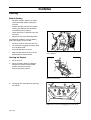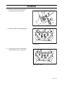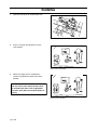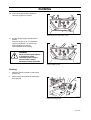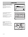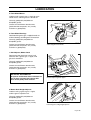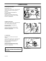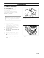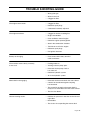
1
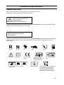
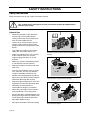
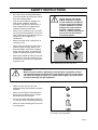
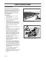
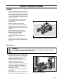
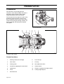
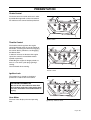
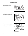
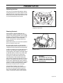
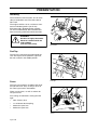
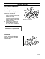
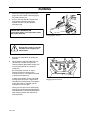
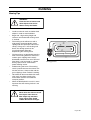
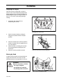
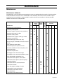
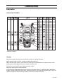
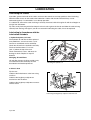
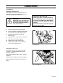
Operator´s manual
ZTH
Please read these instructions carefully and make sure
you understand them before using the machine.
English
OPERATOR’S MANUAL
RIDER
ZTH
Contents
Contents ..................................................................1
Introduction ............................................................3
Congratulations....................................................3
General ................................................................3
Driving and Transport on Public Roads ...............3
Towing .................................................................3
Operating .............................................................3
Good Service .......................................................4
Manufacturing Number ........................................4
Symbols and Decals ..............................................5
Safety Instructions .................................................6
General Use.........................................................6
Driving on Slopes.................................................8
Children................................................................9
Maintenance ........................................................9
Transport............................................................11
Presentation .........................................................12
Control Locations ...............................................12
Choke Control ....................................................13
Throttle Control ..................................................13
Ignition Lock.......................................................13
Hour Meter .........................................................13
Engaging the Mower Deck.................................14
Parking Brake ....................................................14
Seat Locking Device ..........................................14
Adjusting the Seat..............................................15
Steering Controls ...............................................15
Refueling............................................................16
Fuel Tap.............................................................16
Fuses .................................................................16
Lifting Lever for the Mower Deck .......................17
Accessories........................................................17
Running .................................................................18
Before Starting ...................................................18
Starting the Engine ............................................18
Running..............................................................21
Mowing Tips.......................................................23
Stopping the Engine...........................................24
Moving by Hand .................................................24
Maintenance .........................................................25
Maintenance Schedule ......................................25
Ignition System ..................................................27
Checking the Safety System..............................27
Checking the Engine's Cooling Air Intake ......... 29
Checking and Adjusting the Choke Cable......... 29
Replacing the Air Filter...................................... 30
Replacing the Fuel Filter ................................... 31
Checking the Fuel Pump’s Air Filter.................. 31
Checking Tire Pressures................................... 31
Checking the Parking Brake.............................. 32
Checking the Blades ......................................... 32
Adjusting the Mower Deck ................................ 32
Cleaning and Washing ...................................... 32
Lubrication ........................................................... 33
Lubrication Schedule......................................... 33
General ............................................................. 33
Lubricating the Cables ...................................... 34
Lubricating in Accordance with the Lubrication
Schedule ........................................................... 34
Trouble Shooting Guide ..................................... 40
Storage ................................................................. 43
Winter Storage .................................................. 43
Service .............................................................. 43
Technical Data ..................................................... 44
Meas., Weights, Etc. ZTH5223 ZTH6125 ......... 44
Engine ............................................................... 44
Noise Emissions and Cutting Width .................. 45
Electrical System............................................... 45
Transmission..................................................... 45
Mower Deck ...................................................... 45
Accessories....................................................... 45
Service Journal ................................................... 46
Delivery Service ................................................ 46
After the First 8 Hours ....................................... 47
25-Hour Service ................................................ 48
50-Hour Service ................................................ 49
100-Hour Service .............................................. 50
300-Hour Service .............................................. 51
At Least Once Each Year.................................. 52
English-1
English-2
INTRODUCTION
Introduction
Congratulations
Thank you for purchasing a Husqvarna ride-on mower. This machine is built for the greatest efficiency and
rapid mowing primarily of large areas. Controls in one place and a hydrostatic transmission regulated by
steering controls also contribute to the machine’s performance.
This manual is a valuable document. Following the instructions (use, service, maintenance, etc.)
can considerably increase the lifespan of your machine and even increase its resale value.
If you sell your machine, be sure to give the operator’s manual to the new owner.
The final chapter of this operator’s manual comprises a Service Journal. Ensure that service and repair
work is documented. A well kept service journal reduces service costs for the season-based maintenance
and affects the machine’s resale value. Take the operator’s manual along when the machine is left to the
workshop for service.
General
In this operator’s manual, left and right, backward and forward are used in relation to the machine’s normal
driving direction.
Driving and Transport on Public Roads
Check applicable road traffic regulations before driving and transport on public roads. If the machine is
transported, you shall always use approved fastening equipment and ensure that the machine is well
anchored.
Towing
When your machine is equipped with a hydrostatic transmission you should, if necessary, only tow the
machine over short distances and at a low speed, otherwise there is a risk of damaging the transmission.
Operating
This machine is constructed only for mowing grass on lawns and other free and even ground without
obstacles such as stones, tree stubs, etc. The machine can also be used for other tasks when equipped
with special accessories provided by the manufacturer, for which the operating instructions are provided in
conjunction with delivery. All other types of use are incorrect. The manufacturer’s directions concerning
operation, maintenance, and repairs must be carefully followed.
The machine must only be operated, maintained, and repaired by persons that are familiar with the
machine’s special characteristics and who are well versed in the safety instructions.
Accident prevention regulations, other general safety regulations, occupational safety rules, and traffic
regulations must be followed without fail.
Unauthorized modifications to the design of the machine may absolve the manufacturer from liability for any
resulting personal injury or property damage.
English-3
INTRODUCTION
Good Service
Husqvarna’s products are sold all over the world and only in specialized retail trade with complete service.
This ensures that you as a customer receive only the best support and service. Before the product is
delivered, the machine has, for example, been inspected and adjusted by your retailer, see the certificate
in the Service Journal in this operator’s manual.
When you need spare parts or support in service questions, guarantee issues, etc., please consult
the following professional:
This Operator’s Manual belongs to the
machine with manufacturing number:
Engine
Transmission
Manufacturing Number
The machine’s manufacturing number can be found on the printed plate affixed behind the battery under
the seat. Stated on the plate, from the top are:
•
The machine’s type designation (I.D.).
•
The manufacturer's type number (Model).
•
The machine’s serial number (Serial no.)
Please state the type designation and serial number when ordering spare parts.
The engine’s manufacturing number is stated on a barcode decal. This is placed on the left side of the
crankcase, in front of the start motor. The plate states:
•
The engine’s serial number (E/NO).
•
The engine’s type designation (Code).
Please state these when ordering spare parts.
The hydraulic pump’s manufacturing number is stated on a barcode decal affixed to the left side of the
pump housing. The plate states:
•
The pump’s type designation.
•
The pump’s serial number.
The hydraulic motor’s manufacturing number is stated on a round metal plate. This is placed on the gable
inside the motor. The plate states:
•
The hydraulic motor’s type designation and design version.
•
The hydraulic motor’s serial number.
English-4
SYMBOLS AND DECALS
Symbols and Decals
These symbols are found on the machine and in the operator’s manual.
Study them carefully so that you know what they mean.
WARNING!
Xxxxxxx xxxx xxxxxxxx xxx x
Xxxxx xxxxxx xx.
xx xxxxxxxx xxxxx xxx xx.
Used in this publication to notify the reader of a risk of personal injury, particularly if the reader should
neglect to follow instructions given in the manual.
IMPORTANT INFORMATION
Xxxxxxx xxxx xxxxxxxx xxx xxx
xxxx xxxxxx xx.
Used in this publication to notify the reader of a risk of material damage, particularly if the reader should
neglect to follow instructions given in the manual. Used also when there is a potential for misuse or
misassembly.
Reverse
Warning!
Neutral
Parking brake
Fast
Slow
CE
conformity
marking
Battery acid is corrosive, explosive,
and flammable
Choke
Warning! Rotating
blades, keep away from
the discharge deck
Do not stand here
Fuel
Do not touch rotating
parts
Noise emissions to the surroundings
in accordance with the European
Union’s directive. The machine’s
emission is stated in the chapter
TECHNICAL DATA and on the decals.
English-5
SAFETY INSTRUCTIONS
Safety Instructions
These instructions are for your safety. Read them carefully.
WARNING!
This symbol means that important safety instructions need to be emphasized. It
concerns your safety.
General Use
•
Read all instructions in this operator’s
manual and on the machine before
starting it. Ensure that you understand
them and then abide by them.
•
Learn how to use the machine and its
controls safely and learn how to stop
quickly. Also learn to recognize the safety
decals.
•
Only allow the machine to be used by
adults who are familiar with its use.
•
Make sure nobody else is in the vicinity
of the machine when you start the
engine, engage the drive, or run the
machine.
•
Make sure animals and people maintain
a safe distance from the machine.
•
Stop the machine if someone enters the
work area.
•
Clear the area of objects such as stones,
toys, steel wire, etc. that may become
caught in the blades and thrown out.
•
Beware of the discharge deck and do not
point it at any one. Do not use the machine
without the discharge deck in place.
•
Stop the engine and prevent it from starting before you clean the discharge deck.
•
Remember that the operator is
responsible for dangers or accidents.
•
Never take passengers. The machine is
only intended for use by one person.
•
Always look down and behind before and
during reversing maneuvers. Keep a look
out for both large and small obstacles.
•
Slow down before turning.
•
Shut down the blades when not mowing.
8011-512
Read the operator’s manual before starting the
machine
8011-513
Clear the area of objects before mowing
8011-520
Never take passengers
English-6
SAFETY INSTRUCTIONS
•
Be careful when rounding fixed objects,
so that the blades do not hit them. Never
drive over foreign objects.
•
Only use the machine in daylight or in
other well-lit conditions. Keep the
machine a safe distance from holes or
other irregularities in the ground. Pay
attention to other possible risks.
•
Never use the machine if you are tired, if
you have consumed alcohol, or if you are
taking other drugs or medication that can
affect your vision, judgment, or
coordination.
•
Beware of traffic when working near or
crossing a road.
•
Never leave the machine unsupervised
with the engine running. Always shut
down the blades, pull back the parking
brake, stop the engine, and remove the
ignition key before leaving the machine.
•
Never allow children or other persons not
trained in the use of the machine to use
or service it. Local laws may regulate the
age of the user.
•
WARNING!
Engine exhaust and certain
vehicle components contain
or emit chemicals considered
to cause cancer, birth defects,
or other reproductive system
damage. The engine exhaust
contains carbon monoxide,
which is a colorless, poisonous
gas. Do not use the machine
in enclosed spaces.
8011-518
Keep children away from the work area
WARNING!
When using the machine, approved personal protective equipment shall be
used. Personal protective equipment cannot eliminate the risk of injury but it
will reduce the degree of injury if an accident does happen. Ask your retailer
for help in choosing the right equipment.
•
Make sure that you have first aid
equipment close at hand when using the
machine.
•
Never use the machine when barefoot.
Always wear protective shoes or boots,
preferably with steel toecaps.
•
Always wear approved protective glasses
or a full visor when assembling or driving.
•
Never wear loose clothing that can fasten
in moving parts.
8011-292
Personal protective equipment
English-7
SAFETY INSTRUCTIONS
Driving on Slopes
Driving on slopes is one of the operations
where the risk is greatest that the driver will
lose control or the machine will tip over, which
can result in serious injury or death. All
slopes require extra caution. If you cannot
reverse up a slope or if you feel unsure,
do not mow the slope.
Do as follows
•
Remove obstacles such as stones,
tree branches, etc.
•
Mow up and down, not side-to-side.
•
Never drive the rider on terrain that
slopes more than 15°.
•
Avoid starting or stopping on a slope. If
the tires begin to slip, shut down the
blades and drive slowly down the slope.
•
Always drive evenly and slowly on
slopes.
•
Make no sudden changes in speed or
direction.
•
Avoid unnecessary turns on slopes, and
if it proves necessary, turn slowly and
gradually downward, if possible.
•
Watch out for and avoid driving over
furrows, holes, and bumps. On uneven
terrain, the machine can tip more easily.
Long grass can hide obstacles.
•
Drive slowly. Use small movements of
the steering controls.
•
Be extra cautious with any additional
equipment, which can alter the
machine’s stability.
•
Do not mow near verges, ditches, or
banks. The machine can suddenly spin
around if a wheel goes over the edge of a
drop or ditch, or if an edge gives way.
•
Do not mow wet grass. It is slippery, and
the tires can lose their grip, so that the
machine slides.
•
Try not to stabilize the machine by
putting a foot on the ground.
•
When cleaning the chassis, the machine
may never be driven near verges or
ditches.
6003-004
English-8
Mow up and down, not side-to-side
8011-519
Be extra cautious when driving on slopes
SAFETY INSTRUCTIONS
Children
•
Serious accidents may occur if you fail to
be on guard for children in the vicinity of
the machine. Children are often attracted
to the machine and mowing work. Never
assume that children will stay put where
you last saw them.
•
Keep children away from the mowing
area and under close supervision by
another adult.
•
Keep an eye out and shut off the
machine if children enter the work area.
•
Before and during a reversing maneuver,
look backward and downward for small
children.
•
Never allow a child to ride with you.
They can fall off and injure themselves
seriously or prevent risk-free
maneuvering of the machine.
•
Never allow children to operate the
machine.
•
Be particularly cautious near corners,
bushes, trees, or other objects that block
your view.
8011-517
Never allow children to operate the machine
Maintenance
WARNING!
The engine must not be started when the driver’s floor plate or any protective plate
for the mower deck’s drive belt is removed.
•
Stop the engine. Prevent the engine from
starting by removing the spark plug cables
from the spark plugs or by removing the
ignition key before making any
adjustments or performing maintenance.
•
Never fill the fuel tank indoors.
•
Gasoline and gasoline fumes are
poisonous and extremely flammable. Be
especially cautious when handling
gasoline, as carelessness can result in
personal injury or fire.
•
Only store fuel in containers approved for
the purpose.
•
Never remove the fuel tank cap and never
fill the fuel tank while the engine is running.
8011-516
Never fill the fuel tank indoors
English-9
SAFETY INSTRUCTIONS
•
Allow the engine to cool before refueling.
Do not smoke. Do not fill fuel in the
vicinity of sparks or open flames.
•
If leaks arise in the fuel system, the
engine must not be started until the
problem has been resolved.
•
Store the machine and fuel in such a way
that there is no risk of leaking fuel or fuel
vapor leading to damages.
•
Check the fuel level before each use and
leave space for the fuel to expand,
because the heat from the engine and
the sun may otherwise cause the fuel to
expand and overflow.
•
Avoid overfilling. If you spill gasoline on
the machine, wipe up the spill and wait
until it has evaporated before starting the
engine. If you have spilled gasoline on
your clothing, change your clothing.
•
Allow the machine to cool before taking
any actions in the engine room.
•
Be very careful when handling battery
acid. Acid on skin can cause serious
corrosive burns. If you spill battery acid
on your skin, rinse immediately with
water.
•
Acid in the eyes can cause blindness,
contact a doctor immediately.
•
Be careful when servicing the battery.
Explosive gases form in the battery. Never
perform maintenance on the battery when
smoking or near open flames or sparks.
The battery can explode and cause
serious injury/damage.
•
Ensure that nuts and bolts, especially the
fastening bolts for the blade attachments,
are properly tightened and that the
equipment is in good condition.
•
Do not modify safety equipment. Check
regularly to be sure it works properly. The
machine must not be driven with
defective or unmounted protective plates,
protective cowlings, safety switches, or
other protective devices.
•
Do not change the settings of governors
and avoid running the engine with overly
high engine speeds. If you run the
engine too fast, you risk damaging the
machine components.
English-10
WARNING!
The engine, the exhaust system,
and the hydraulic system’s
components become very warm
during operation.
Risk for burns if touched.
WARNING!
The battery contains lead and
lead compounds, chemicals that
are considered to cause cancer,
birth defects, and other
reproductive system damage.
Wash your hands after touching
the battery.
6003-009
Do not smoke when performing maintenance on the
battery. The battery can explode and cause serious
injury/damage
SAFETY INSTRUCTIONS
•
Never use the machine indoors or in
spaces lacking proper ventilation. The
exhaust fumes contain carbon monoxide,
an odorless, poisonous, and lethal gas.
•
Stop and inspect the equipment if you
run over or into anything. If necessary,
make repairs before starting.
•
Never make adjustments with the engine
running.
•
The machine is tested and approved only
with the equipment originally provided or
recommended by the manufacturer.
•
The blades are sharp and can cause
cuts and gashes. Wrap the blades or use
protective gloves when handling them.
•
Check the parking brake’s functionality
regularly. Adjust and service as
necessary.
•
The BioClip deck shall only be used
when higher quality mowing is desired in
familiar areas.
•
Reduce the risk of fire by removing
grass, leaves, and other debris that may
have fastened in the machine. Allow the
machine to cool before putting it in
storage.
8011-515
Never drive the machine in an enclosed space
Transport
•
•
•
The machine is heavy and can cause
serious crushing injuries. Be extra
cautious when it is loaded on or
unloaded from a vehicle or trailer.
Use an approved trailer to transport the
machine. Activate the parking brake, turn
off the fuel supply, and fasten the
machine with approved fastening
devices, such as bands, chains, or ropes,
when transporting.
Check and abide by local traffic
regulations before transporting or driving
the machine on any road.
8011-514
Clean the machine regularly
IMPORTANT INFORMATION
The parking brake is not sufficient to lock
the machine in place during transport.
Ensure that the machine is well fastened
to the transport vehicle. Reverse the
machine onto the transport vehicle to
avoid tipping it over.
English-11
PRESENTATION
Presentation
This operator’s manual describes the
Husqvarna Lever-Steered Rider. The rider is
fitted with a Kawasaki four-stroke V-Twin
engine developing 23/25 horse power.
Transmission from the engine is made via two
belt-driven hydraulic pumps, which in turn
drive a hydraulic motor for each drive wheel.
Using the left and right steering controls, the
flow is regulated and thereby the direction
and speed.
8011-583
Lever-Steered Rider
8011-602
Locations of the controls
Control Locations
1.
Steering control, left and right
8.
Fuel tank cap
2.
Hour meter
9.
Fuel tap
3.
Parking brake
10.
Seat adjustment lever
4.
Control for engaging the mower deck
11.
Choke control
5.
Ignition lock
12.
Throttle - regulates the engine speed
6.
Fuses
13.
Cutting height adjuster
7.
Seat lock lever
English-12
PRESENTATION
Choke Control
The choke control is used for cold starts in order
to provide the engine with a richer fuel mixture.
For cold starts the control shall be pulled out.
8011-508
Choke control
Throttle Control
The throttle control regulates the engine
speed and thereby even the rate of rotation of
the blades, assuming the control for engaging
the mower deck is pulled out, see Engaging
the Mower Deck.
In order to increase or decrease the engine
speed, the control is moved downward or
upward respectively.
Avoid idling the engine for longer periods, as
there is a risk of the spark plugs gaining a
coating.
Use full throttle when mowing.
8011-509
Throttle control
Ignition Lock
The ignition key is placed on the driver’s
panel and is used to start the machine.
IMPORTANT INFORMATION
Do not run the start motor for more than
five seconds each time. If the engine does
not start, wait about 10 seconds before retrying.
Hour Meter
The hour meter displays the total operating
time.
8011-521
Ignition key and hour meter
English-13
PRESENTATION
Engaging the Mower Deck
In order to engage the mower deck, pull the
button out; the mower deck is disengaged
when the button is depressed.
8011-510
Engaging the mower deck
Parking Brake
The parking brake is found on the left of the
machine. Pull the lever backward to activate
the brake and forward to release it.
8011-511
Parking brake not activated
Seat Locking Device
To the left behind the seat is a locking device
that locks the seat into its folded position. The
seat has a linked fixture at the front edge and
can be folded forward when the locking
device is moved aside.
8011-523
The seat’s locking device
English-14
PRESENTATION
Adjusting the Seat
The seat can be adjusted lengthways. When
making adjustments, the lever under the front
edge of the seat is moved to the left (as seen
by the driver in the seat), after which the seat
can be moved backward or forward.
8011-562
Lengthways adjustment
Steering Controls
The machine’s speed and direction are
continuously variable using the two steering
controls. The steering controls can be moved
forward or backward about a neutral position.
Furthermore, there is a neutral position,
which is locked if the steering controls are
moved outward.
When both controls are in the neutral position
(N), the machine stands still.
By moving both controls an equal amount
forward or backward, the machine moves in a
straight line forward or backward respectively.
8011-522
In order, for example, to turn right while moving
forward, move the right control towards the
neutral position. The rotation of the right wheel
is reduced and the machine turns to the right.
Turning on the spot can be achieved by
moving one control backward (behind the
neutral position) and carefully moving the
other steering control forward from its neutral
position. The rotation direction when turning
on the spot is determined by which steering
control is moved backward behind the neutral
position. If the left steering control is pulled
backward, the machine turns to the left.
Steering controls
WARNING!
The machine can turn very
rapidly if one steering control
is moved much further forward
than the other.
If the steering controls are in uneven
positions when standing still or do not fit in
the slots for moving the controls outward,
they can be adjusted using the adjustment
screws, not the link system, for the controls.
English-15
PRESENTATION
Refueling
The machine has two fuel tanks, one on each
side just behind the seat. The tanks take 22
liters each.
The engine shall be run on a minimum of 87octane unleaded gasoline (no oil mix).
Environmentally adapted alkylate gasoline
can be used beneficially. See also Technical
Data concerning methanol and ethanol fuels.
WARNING!
Gasoline is highly flammable.
Observe caution and fill the
tank outdoors
(see the safety rules).
8011-524
Fuel tanks
Fuel Tap
The fuel tap is placed to the right behind the
seat. The tap has three positions; right tank,
left tank, and off in the middle position.
8011-506
Fuses
Fuel tap
The fuses are located in a holder to the left of
the hydraulic tank. They are flat pin fuses of
the same type used in automobiles.
There are two fuses, as well as sockets for
two spare fuses.
Fuse ratings and functions moving from the
right:
•
20 A, Primary fuse.
•
7.5 A, Mower deck coupling.
•
Socket for spare fuse.
•
Socket for spare fuse.
8011-596
Fuses
English-16
PRESENTATION
Lifting Lever for the Mower Deck
The lifting lever is used to place the mower
deck in the transport position or one of the 17
different cutting height positions.
The cutting height is set by placing a peg in
the hole for the desired cutting height and the
peg is then locked on the inside (hidden in the
illustration) with the supplied pin.
1.
Pull the lever backward to the locked
position to engage the transport position.
The deck is then raised.
2.
Depress the lock handle, counter hold,
and move the lifting lever forward toward
the peg to engage the set cutting height.
The deck is then lowered.
3.
8011-525
The mower deck’s lifting lever
The lifting lever can also be used to
temporarily adjust the cutting height,
such as when passing a minor bump in
the lawn.
IMPORTANT INFORMATION
In order to obtain an even cutting height it
is important that the air pressure in all
four tires is the same (1 bar).
Accessories
For mulching, there is a BioClip attachment
available. This is mounted underneath the
mower deck and comprises control plates
and BioClip blades.
8011-566
BioClip attachment
English-17
RUNNING
Running
Before Starting
•
Read the sections Safety Instructions
and Presentation before starting the
machine.
•
Perform the daily maintenance before
starting (see Maintenance Schedule
in the Maintenance section).
•
Check that there is sufficient fuel in the
fuel tanks.
•
Adjust the seat to the desired position.
The following conditions must be fulfilled
before the engine can be started:
•
the driver must be seated on the seat,
•
the control for engaging the mower deck
must be depressed,
•
the parking brake must be on,
•
both steering controls must be in the
locked (outer) neutral position.
8011-527
Start conditions
Starting the Engine
1.
Sit on the seat.
2.
Raise the mower deck by pulling the
lifting lever backward to the locked
position (transport position).
Activate the parking brake.
8011-552
Raise the mower deck
3.
Disengage the mower deck by pressing
the control.
8011-510
Depress the control for disengaging the mower deck
English-18
RUNNING
4.
Move the steering controls outward to
the locked (outer) neutral position.
8011-526
Steering controls in the outward, locked neutral position
5.
Move the throttle to the middle position.
8011-509
Set the throttle
6.
If the engine is cold, the choke control
shall be pulled out to its end position.
8011-508
Set the choke control
English-19
RUNNING
7.
Open the fuel tap for the selected fuel tank.
8011-506
Open the fuel tap
8.
Press in and turn the ignition key to the
start position.
8011-559
Turn to the start position
9.
When the engine starts, immediately
release the ignition key back to the drive
position.
IMPORTANT INFORMATION
Do not run the start motor for more than
5 seconds each time. If the engine does
not start, wait about 10 seconds before retrying.
8011-560
Return to drive position
English-20
RUNNING
10. Press the choke control in gradually
when the engine has started.
8011-508
Gradually press in the choke control
11. Set the desired engine speed with the
throttle.
Allow the engine to run at a moderate
speed, ”half throttle”, for 3-5 minutes
before loading it too heavily.
Use full throttle when mowing.
WARNING!
Never run the engine indoors,
in enclosed or poorly
ventilated spaces. Engine
exhaust fumes contain
poisonous carbon monoxide.
8011-509
Set the engine speed
Running
1.
Move the steering controls to the neutral
position (N).
2.
Release the parking brake by moving the
lever forward.
8011-511
Released parking brake
English-21
RUNNING
3.
Select the cutting height by placing the
peg in one of the holes. Lock the peg on
the inside with the pin.
4.
Press in the stop handle, counter hold,
and carefully move the lifting lever
forward from the transport position
toward the peg.
IMPORTANT INFORMATION
The mower deck’s anti-scalp rollers shall
be evenly adjusted.
8011-561
Cutting height selection
WARNING!
Ensure that no one is near the
machine when engaging the
mower deck.
5.
Engage the mower deck by pulling out
the lever.
6.
The machine’s speed and direction are
continuously variable using the two
steering controls. When both controls are
in the neutral position, the machine
stands still.
By moving both controls an equal
amount forward or backward, the
machine moves in a straight line forward
or backward respectively.
In order, for example, to turn right while
moving forward, move the right control
towards the neutral position. The rotation
of the right wheel is reduced and the
machine turns to the right.
Turning on the spot can be achieved by
moving one control backward (behind the
neutral position) and carefully moving the
other steering control forward from its
neutral position.
English-22
8011-510
Engaging the mower deck
RUNNING
Mowing Tips
WARNING!
Clear the lawn of stones and
other objects that can be
thrown out by the blades.
•
Localise and mark rocks and other fixed
objects in order to avoid collisions.
•
Begin with a high cutting height and
reduce it until the desired mowing result
is attained.
•
The mowing result will be best with a
high engine speed (the blades rotate
rapidly) and low speed (the rider moves
slowly). If the grass is not too long and
dense, the driving speed can be
increased without noticeably
depreciating the mowing result.
•
The finest lawns are obtained by mowing
often. The mowing becomes more even
and the grass clippings more evenly
distributed over the mown area. The total
time taken is not increased as a higher
driving speed can be used without
poorer mowing results.
•
Avoid mowing wet lawns. The mowing
result is poorer because the wheels sink
into the soft lawn, clumps build, and the
grass clippings fasten under the cowling.
•
Hose beneath the mower deck with water
after each use. When cleaning, the
mower deck shall be raised into the
transport position.
•
When the BioClip deck is used, it is extra
important that the mowing interval is not
too long.
8011-603
Mowing patterns
WARNING!
Never drive the rider on terrain
that slopes more than 15°.
Mow slopes up and down,
never side-to-side. Avoid
sudden directional changes.
English-23
RUNNING
Stopping the Engine
Feel free to let the engine idle a minute in
order to attain normal operating temperature
before stopping it if it has been worked hard.
Avoid idling the engine for longer periods, as
there is a risk of the spark plugs gaining a
coating.
1.
Disengage the mower deck by
depressing the control.
8011-510
Disengage the mower deck
2.
Raise the mower deck by pulling the
lifting lever backward to the transport
position.
3.
Move the throttle to the minimum position
(tortoise symbol). Turn the ignition key to
the stop position.
4.
When the rider is standing still, activate
the parking brake by pulling the lever
backward.
5.
Move the steering controls outward.
8011-552
Raise the mower deck with the lifting lever
Moving by Hand
In order for the machine to be moved with the
engine turned off, the vent screws on both
hydraulic pumps must be opened 1/4-1/2 turn.
WARNING!
Make no adjustments without:
- the engine stopped,
- the ignition key removed,
- the parking brake activated.
8011-507
Vent screw on the hydraulic pump
English-24
MAINTENANCE
Maintenance
Maintenance Schedule
The following is a list of maintenance procedures that must be performed on the machine. For those points
not described in this manual, visit an authorized service workshop. An annual service carried out by an
authorized service workshop is recommended in order to maintain your machine in the best possible
condition and to ensure safe operation.
Daily
maintenance
Maintenance
Weekly At
mainte- least
nance once
each
Page Before After
year
-
❍
Check the parking brake
32
●
Check the engine’s oil level (every refueling)
35
●
Check the fuel pump’s air filter
31
Check the safety system
27
Check/clean the engine’s cooling air intake
29
●
Check the mower deck
32
●
Check fastenings (screws, nuts, etc.)
-
❍
Start the engine and blades, listen for unusual
sounds
Clean under the mower deck
-
❍
32
●
Check the hydraulic system’s oil level
34
Check for fuel and oil leakages
25
Check for damage
-
❍
●
31
Thoroughly clean around the engine
-
❍
Thoroughly clean around the hydraulic system
-
❍
Clean around belts, belt pulleys, etc.
-
❍
Lubricate the belt adjuster, mower deck
37
●
Lubricate the belt adjuster, hydraulic pumps
39
●
Lubricate all cables
36
●
Lubricate the driver’s seat mechanism
34
●
Lubricate the throttle
36
●
Clean the engine’s cooling air intake
29
Lubricate the front wheel mounts
(every 200 hours)
Lubricate the front wheel bearings
37
37
300
●
❍
-
100
●
-
Lubricate links in the mower deck
50
●
Check the condition of belts, belt pulleys, etc.
Check the tire pressures
Maintenance interval
in hours
●
●
❍
●
●
English-25
MAINTENANCE
Weekly At
mainte- least
nance once
each
Page Before After
year
Daily
maintenance
Maintenance
Maintenance interval
in hours
25
50
Lubricate the steering control shafts
38
●
Lubricate the mower deck’s struts
38
●
Lubricate the mower deck’s cutting height adjuster
37
●
100
300
-
❍
Clean the air cleaner’s pre-filter (Oil-foam)
30
●
Clean the air cleaner’s filter cartridge 2)
(paper filter)
30
●
Change the engine oil 1)
Change the hydraulic oil (every 300 hours)
35
●
-
❍
Replace the engine oil filter (every 200 hours)
39
●
●
Clean/replace the spark plugs
27
●
●
Replace the fuel filter
31
●
●
Clean the cooling fins
-
❍
❍
Check the play in the engine valves 4)
Replace the air cleaner’s pre-filter (Oil-foam)
-
❍
❍
30
●
●
Replace the air filter (paper filter) 2)
(every 200 hours)
30
●
Perform the 300-hour service 4)
Check/adjust the parking brake
51
❍
-
❍
Check/adjust the cutting height
1)
●
●
●
❍
●
❍
❍
First change after 8 hours. When operating with a heavy load or at high ambient temperatures, replace every 50 hours. 2) In dusty conditions, cleaning
and replacement are required more often. 3) For daily use, the machine shall be lubricated twice weekly. 4) Performed by authorized service workshop.
● = Described in this manual
❍ = Not described in this manual
WARNING!
No adjustments or maintenance to be carried out unless:
• The engine is stopped.
• The ignition key has been removed.
• The parking brake is on.
English-26
MAINTENANCE
Ignition System
The engine is equipped with an electronic ignition system. Only the spark plugs require maintenance.
For recommended spark plugs, see Technical Data.
1.
Remove the ignition cable shoe and
clean around the spark plug.
2.
Remove the spark plug with a 13/16"
(21 mm) spark plug socket wrench.
3.
Check the spark plug. Replace the spark
plug if the electrodes are burned or if the
insulation is cracked or damaged. Clean
the spark plug with a steel brush if it is to
be reused.
4.
Measure the electrode gap with a gapping tool. The gap shall be 0.75 mm. Adjust as necessary by
bending the side electrode.
5.
Reinsert the spark plug, turning by hand to avoid damaging the threads.
6.
After the spark plug is seated, tighten it using a spark plug wrench so that the washer is compressed.
A used spark plug should be turned 1/8–1/4 of a turn from the seated position. A new spark plug
should be turned 1/2 a turn from the seated position.
7.
Replace the ignition cable shoe.
IMPORTANT INFORMATION
Fitting the wrong spark plug type can
damage the engine.
Inadequately tightened spark plugs can
cause overheating and damage the
engine. Tightening the spark plugs too
hard can damage the threads in the
cylinder head.
Checking the Safety System
The machine is equipped with a safety
system that prevents starting or driving under
the following conditions.
The engine can only be started when:
1.
The mower deck is disengaged.
2.
The steering controls are in the outer,
locked neutral position.
3.
The driver is sitting in the driver’s seat.
4.
The parking brake is on.
Make daily inspections to ensure that the
safety system works by attempting to start the
engine when one of the conditions is not met.
Change the conditions and try again.
If the machine starts when one of these
conditions is not met, turn the machine off
and repair the safety system before using the
machine again.
Check that the engine stops if one, after
having released the parking brake,
temporarily stands from the driver’s seat
(whether the mower deck is engaged or not).
8011-527
Conditions for starting
IMPORTANT INFORMATION
In order to be able to drive, the driver
must sit in the seat and release the
parking brake before the steering
controls can be moved into the neutral
position, otherwise the engine will stop.
Check that the engine stops if the mower deck is engaged and one temporarily stands up.
English-27
MAINTENANCE
Start motor
Ignition system
Works
Does not work
8011-553
Safety system
English-28
MAINTENANCE
Checking the Engine's Cooling Air Intake
Check that the engine’s cooling air intake is
free from leaves, grass, and dirt.
If the cooling air intake is clogged, engine
cooling deteriorates, which can lead to
engine damage.
8011-625
Checking and Adjusting
the Throttle Cable
Check and clean the cooling air intake
Check that the engine responds to throttle
increases and that a good engine speed is
attained at full throttle.
If doubts arise, contact the service workshop.
If adjustments are necessary, they can be
made as follows for the lower cable:
1.
Loosen the clamping screw for the
cable’s outer casing and move the
throttle to the full throttle position.
2.
Check that the throttle cable is mounted
in the correct hole in the lower lever, see
illustration.
3.
Push the throttle cable’s outer casing as
far to the left as possible and tighten the
clamping screw.
8011-554
Adjusting the throttle cable
Checking and Adjusting the Choke
Cable
If the engine produces black smoke or is
difficult to start, this can be because the choke
cable is incorrectly adjusted (upper cable).
If doubts arise, contact the service workshop.
If adjustments are necessary, they can be
made as follows:
1.
Loosen the clamping screw for the
cable’s outer casing and move the choke
lever to the full choke position.
2.
Check that the choke cable is mounted in
the upper lever, see illustration. Push the
choke cable’s outer casing as far to the
right as possible and tighten the
clamping screw.
8011-555
Adjusting the choke cable
English-29
MAINTENANCE
Replacing the Air Filter
If the engine seems weak or runs unevenly,
the air filter may be clogged. If run with a
soiled air filter, the spark plugs can obtain a
coating that disrupts operation.
For this reason, it is important to replace the air
filter regularly (see the heading Maintenance
Schedule for the proper service interval).
Cleaning/replacing the air filter is carried out
as follows:
8011-556
Remove the air filter cowling
WARNING!
Allow the exhaust system to
cool before performing
service. Risk for burns.
1.
Remove the two plastic fasteners on the
top of the air filter cowling and remove
the air filter cowling.
2.
Remove the foam rubber pre-filter and
clean using a mild detergent.
Squeeze it dry with a clean cloth.
8011-557
Remove the pre-filter
3.
Remove the wing nuts for the air filter
and remove the paper filter. Tap the
paper filter against a fixed surface to
remove dust. If the paper filter is still
dirty, it must be replaced.
IMPORTANT INFORMATION
Do not used compressed air to clean the
air filter.
Do not wash the paper filter.
Do not oil the paper filter.
4.
8011-558
Remove the paper filter
Refit the air filter as follows:
Check that the seal on the bottom of the
paper filter is whole.
Mount the paper filter in the air filter
housing and tighten the wing nuts.
5.
Refit the pre-filter on the paper filter.
6.
Replace the cowling over the air filter
housing. Do not over tighten the plastic
fasteners.
English-30
8009-181
Remove dust
MAINTENANCE
Replacing the Fuel Filter
Replace the line-mounted fuel filter every
100 hours (once per season) or more
regularly if it is clogged.
Replace the filter as follows:
1.
Move the hose clamps away from the
filter. Use flat-nosed pliers.
2.
Pull the filter loose from the hose ends.
3.
Push the new filter into the hose ends.
Position the filter with the ”FLOW” arrow
pointing up toward the fuel pump. If
necessary, a soap solution can be
applied to the filter ends to ease
mounting.
4.
8009-146
Fuel filter
Move the hose clamps back toward the
filter.
Checking the Fuel Pump’s Air Filter
Regularly check that the fuel pump’s air filter
is free from dirt.
Remove the screws and open the pump, no
hoses need be removed.
The filter can be cleaned with a brush if
necessary.
Replace the filter on the console.
8009-147
The fuel pump’s air filter
Checking Tire Pressures
All four tires shall have a pressure of 1 bar.
8011-564
Tire pressures
English-31
MAINTENANCE
Checking the Parking Brake
Visually check that no damage is found on
the lever, links, or switch belonging to the
parking brake. Perform a test drive and check
that there is a braking effect.
To adjust the handbrake, contact the service
workshop.
8011-511
The parking brake in the disengaged position
Checking the Blades
In order to attain the best mowing effect, it is
important that the blades are well sharpened
and not damaged.
Bent or cracked blades or blades with large
nicks in shall be replaced.
Check the blade mounts.
IMPORTANT INFORMATION
The replacement or sharpening of blades
ought to be carried out by an authorized
service workshop.
8011-604
Check the blades
Damaged blades should be replaced when
hitting obstacles that result in a breakdown.
Let the service workshop decide whether the
blade can be repaired/ground or must be
discarded.
Adjusting the Mower Deck
Contact an authorized service workshop.
Cleaning and Washing
Regular cleaning and washing, especially
under the mower deck, will increase the
machine’s lifespan. Make it a habit to clean
the machine directly after use, before the dirt
sticks.
8011-514
Cleaning
English-32
LUBRICATION
Lubrication
Lubrication Schedule
(2x)
(2x)
( )
(2x)
(2x)
(2x)
8011-620
Lubrication schedule
General
Remove the ignition key to prevent unintentional movements during lubrication.
When lubricating with an oilcan, it ought to be filled with engine oil.
When lubricating with grease, unless otherwise stated, grease 503 98 96-01 or another chassis or ball
bearing grease offering good corrosion protection shall be used.
For daily use, the machine shall be lubricated twice weekly.
Wipe away excess grease after lubrication.
It is important to avoid getting lubricant on the belts or the drive surfaces on the belt pulleys. Should this
happen, attempt to clean them with spirits. If the belt continues to slip after cleaning with spirits, it must be
replaced. Gasoline or other petroleum products must not be used to clean belts.
English-33
LUBRICATION
Lubricating the Cables
If possible, grease both ends of the cables and move the controls to end stop positions when lubricating.
Refit the rubber covers on the cables after lubrication. Cables with sheaths will bind if they are not
lubricated regularly. If a cable binds, it can disrupt operation.
If a cable binds, remove the cable and hang it vertically. Lubricate it with thin engine oil until the oil begins to
escape from the bottom.
Tip: Fill a small plastic bag with oil and tape it so that it seals against the sheath and allow the cable to hang
vertically from the bag overnight. If you do not succeed in lubricating the cable, it must be replaced.
Lubricating in Accordance with the
Lubrication Schedule
1. Hydraulic System, Oil Level
The hydraulic oil and filter shall be replaced
every 300 hours, and at least once a year.
Contact an authorized service workshop.
Check the oil level in the hydraulic tank daily.
The level shall be about 19 - 25 mm
(3/4"-1") below the top of the tank.
Check connections, hoses, and tubes for
damage or leaks. Replace or repair if
doubtful.
Changing Oil and Filters
Oil and filter changes shall be carried out by
an authorized service workshop and are
described in the Workshop Manual.
8011-565
Checking the hydraulic oil
2. Driver’s Seat
Tip the seat.
Lubricate the linked mount at the front using
an oilcan.
Lubricate the lengthways adjustment
mechanism with the oilcan.
Lubricate the lengthways adjustment runners
with the oilcan.
8011-571
Lubricating the lengthways adjuster under the seat
English-34
LUBRICATION
3. Engine Oil
Changing the Engine Oil
The engine oil shall be changed for the first
time after 8 hours of operation. Thereafter, it
shall be changed every 100 hours.
WARNING!
Engine oil can be very hot if it is
drained directly after stopping
the engine. Allow the engine to
cool somewhat first.
1.
Place the machine on a flat surface.
2.
Place a container under the engine where
the hose from the oil drainage tap exits.
3.
Remove the dipstick and open the
drainage tap.
4.
Allow the oil to run out into the container.
5.
Then close the oil drainage tap.
6.
Replace the oil filter if necessary.
7.
Fill with new engine oil in accordance
with Checking the Oil Level.
IMPORTANT INFORMATION
Used engine oil is a health hazard and
must not be disposed of on the ground or
in nature; it should always be disposed
of at a workshop or appropriate disposal
location.
Avoid skin contact; wash with soap and
water in case of spills.
8011-572
Oil drainage tap
Checking the Oil Level
Check the oil level in the engine when the
machine is standing horizontally and the
engine is stopped.
Remove the dipstick, wipe it clean, and then
replace it.
The dipstick shall not be screwed into place.
Take the dipstick out again and read the oil
level.
8011-569
Remove the dipstick
English-35
LUBRICATION
The oil level shall lie between the markings
on the dipstick. If the level is approaching the
”ADD” mark, top up the oil to the ”FULL” mark
on the dipstick.
ADD
Never fill to above the ”FULL” mark.
FULL
The oil is topped up through the hole the
dipstick sits in.
ADD
FULL
8009-159
The dipstick markings
Use engine oil SAE 30 or SAE 10W-30 or,
alternately, 10W/40, class SC–SH
(over 0 °C/+32 °F).
-20 C
-10 C
0C
10 C
20 C
40 C
SAE40
Over +20 °C/+68 °F SAE 40 can be used.
SAE30
Use engine oil SAE 5W-20, class SC–SH
(under 0 °C/+32 °F).
The engine holds 1.5 liters of oil excluding
the filter (including filter 1.7 liters).
30 C
SAE10W-30/SAE10W-40
SAE5W-20
-4 F
14 F
32 F
50 F
68 F
86 F
104 F
8009-140
Engine oils
4. Throttle and Choke Cables, Lever
Bearings
Lubricate the cable ends by the carburetor
with the oilcan. Move the controls to the end
points and lubricate again.
The throttle cable is also lubricated by the
control when the control console is removed.
8011-605
Throttle and choke cables by the carburetor
English-36
LUBRICATION
5. Front Wheel Mount
Lubricate with a grease gun, 1 nipple for each
wheel mount, until the grease is forced out.
Use only good quality molybdenum
disulphide grease.
Grease from well-known brand names
(petrochemical companies, etc.) usually
maintains a good quality.
6. Front Wheel Bearings
Lubricate with a grease gun, 1 nipple for each set
of wheel bearings, until the grease is forced out.
Use only good quality molybdenum
disulphide grease.
8011-573
Grease from well-known brand names
(petrochemical companies, etc.) usually
maintains a good quality.
Lubricating the front wheels
7. Belt Adjuster, Mower Deck
Remove the foot plate (two screws) and
lubricate with a grease gun, 1 nipple, until
grease is forced out.
Use only good quality molybdenum
disulphide grease.
Grease from well-known brand names
(petrochemical companies, etc.) usually
maintains a good quality.
IMPORTANT INFORMATION
Be spartan and remove excess lubricant so
that is does not come into contact with
belts or belt pulley drive surfaces.
8011-576
The belt adjuster grease nipple
8. Mower Deck Height Adjuster
Lubricate using a grease gun, 1 nipple,
until the grease squeezes out.
Use only good quality molybdenum
disulphide grease.
Grease from well-known brand names
(petrochemical companies, etc.) usually
maintains a good quality.
8011-574
Lubricating the cutting height adjuster
English-37
LUBRICATION
9. Steering Control Shafts
Tip the driver’s seat.
Lubricate with a grease gun, 1 nipple for each
steering control shaft, until the grease is
forced out.
Use only good quality molybdenum
disulphide grease.
Grease from well-known brand names
(petrochemical companies, etc.) usually
maintains a good quality.
8011-578
Lubricating the steering control shafts
10. Mower Deck Struts
Lubricate with a grease gun, 1 nipple for each
strut, until the grease is forced out.
Use only good quality molybdenum
disulphide grease.
Grease from well-known brand names
(petrochemical companies, etc.) usually
maintains a good quality.
8011-577
Lubricating struts
11. Brake Arms
Remove one rear wheel at a time (four
screws).
Lubricate with a grease gun, 1 nipple for each
brake arm, until the grease is forced out.
Use only good quality molybdenum
disulphide grease.
Grease from well-known brand names
(petrochemical companies, etc.) usually
maintains a good quality.
IMPORTANT INFORMATION
Be spartan and remove excess lubricant so
that is does not come into contact with the
brake band.
English-38
8011-579
Lubricating brake arms
LUBRICATION
12. Belt Adjuster, Hydraulic Pumps
Lubricate using a grease gun, 1 nipple, until
the grease squeezes out.
Use only good quality molybdenum
disulphide grease.
Grease from well-known brand names
(petrochemical companies, etc.) usually
maintains a good quality.
IMPORTANT INFORMATION
Be spartan and remove excess lubricant so
that is does not come into contact with
belts or belt pulley drive surfaces.
8011-575
Lubricating the belt adjuster
13. Changing the Oil Filter
1.
Drain the engine oil in accordance with
the work description under the heading
Engine Oil/Change Engine Oil.
2.
Disassemble the oil filter. If necessary,
use a filter remover.
3.
Wipe new, clean engine oil onto the seal
for the new filter.
4.
Mount the filter by hand with + 3/4 turn.
5.
Run the engine warm, then check that
there are no leaks around the oil filter
seal.
6.
Check the oil level in the engine, top up
if necessary. The oil filter holds 0.2 liters
of oil.
8011-570
Changing the oil filter
English-39
TROUBLE SHOOTING GUIDE
Trouble Shooting Guide
Problem
Cause
The engine will not start.
•
The control for engaging the mower deck is
not depressed.
•
The steering controls are not locked in the
neutral position.
•
The driver is not sitting in the driver’s seat.
•
The parking brake is not activated.
•
The battery is dead.
•
Contamination in the carburetor or fuel line.
•
The fuel supply is closed or the tap
for the fuel tanks is in the wrong position.
•
Clogged fuel filter or fuel line.
•
Dead battery.
•
Poor contacts on the battery terminal
cable connections.
•
Fuse blown.
•
Ignition system faulty.
•
Fault in the starter motor safety circuit.
See Safety system on page 28.
•
Faulty carburetor.
•
The choke control is pulled out with a warm engine.
•
Defective valves.
•
Defective piston, cylinder, piston ring, or
cylinder head seal.
•
The cylinder head bolts are loose.
•
Clogged fuel filter or jet.
•
Clogged ventilation valve on the fuel cap.
•
Fuel tank empty.
•
Defective spark plugs.
•
The spark plugs are loose.
•
Defective ignition cable.
•
Defective spark plug electrode.
•
Defective spark plug connection.
•
Rich fuel mixture or fuel-air mixture.
The starter motor does not turn the engine over.
The engine runs unevenly.
English-40
TROUBLE SHOOTING GUIDE
•
Wrong fuel type.
•
Water in the fuel.
•
Clogged air filter.
•
Clogged air filter.
•
Defective spark plugs.
•
Carburetor incorrectly adjusted.
•
Clogged air intake or cooling fins.
•
Engine overloaded.
•
Poor ventilation around engine.
•
Defective engine speed regulator.
•
Soot in the combustion chamber.
•
Too little or no oil in the engine.
•
Defective spark plugs.
•
Pre-ignition incorrect.
Battery not charging.
•
Poor contact with battery terminal
cable connectors.
The machine moves slowly, unevenly,
•
Parking brake on.
or not at all.
•
Venting valve on pump open.
•
Drive belt for the pump slack or
has come off.
•
Defective hydraulic system.
•
Air in the hydraulic system.
•
Drive belt for the mower deck has come loose.
•
Contact for the electromagnetic coupling
has loosened.
•
The control for engaging the mower deck is
faulty or has come loose from the cable contact.
•
The fuse has blown.
•
Different air pressure in the tires on the left and
right sides.
•
Bent blades.
•
The chains for suspending the mower deck
The engine seems weak.
The engine overheats.
Mower deck not engaging.
Uneven mowing results.
English-41
TROUBLE SHOOTING GUIDE
are uneven.
The machine vibrates.
English-42
•
The chain fixture has come loose.
•
The blades are blunt.
•
Driving speed too high.
•
The grass is too long.
•
Grass collected under the mower deck.
•
The blades are loose.
•
The blades are incorrectly balanced.
•
The engine is loose.
STORAGE
Storage
To ready the machine for storage, follow these
steps:
Winter Storage
1.
Thoroughly clean the machine, especially
under the mower deck. Touch up damage to
the paint and spray a thin layer of oil on the
underside of the mower deck in order to avoid
corrosion.
2.
Inspect the machine for worn or damaged
parts and tighten any nuts or screws that may
have become loose.
3.
Change the engine oil; dispose of properly.
4.
Empty the fuel tanks or add a fuel stabilizer.
Start the engine and allow it to run until even
the carburetor is drained of fuel or the
stabilizer has reached the carburetor.
5.
Remove the spark plugs and pour about a
tablespoon of engine oil into each cylinder.
Turn over the engine so that the oil is evenly
distributed and then refit the spark plugs.
6.
Lubricate all grease nipples, joints, and axles.
7.
Remove the battery. Clean, charge, and store
the battery in a cool place, but protect it from
direct cold.
8.
Store the machine in a clean, dry place and
cover it for extra protection.
At the end of the mowing season, the machine
should be readied for storage (or if it will not be in
use for longer than 30 days). Fuel allowed to
stand for long periods of time (30 days or more)
can leave sticky residues that can plug the
carburetor and disrupt engine function.
Fuel stabilizers are an acceptable option as
regards sticky residues during storage. If alkylate
gasoline (Aspen) is used, stabilizers are
unnecessary because this fuel is stable. However,
you should avoid switching between regular and
alkylate gasoline as sensitive rubber components
can harden. Add stabilizer to the fuel in the tank or
in the storage container. Always use the mixing
ratios specified by the manufacturer of the
stabilizer. Run the engine for at least 10 minutes
after adding the stabilizer so that it reaches the
carburetor. Do not empty the fuel tank and the
carburetor if you have added stabilizer.
WARNING!
Never store an engine with fuel
in the tank indoors or in poorly
ventilated spaces where fuel
vapor can come in contact with
open flames, sparks, or a pilot
light such as in a boiler, hot
water tank, clothes drier, etc.
Handle the fuel with care. It is
very flammable and careless
use can cause serious personal
injury and property damage.
Drain the fuel into an approved
container outdoors and far
away from open flame. Never
use gasoline for cleaning. Use
a degreaser and warm water
instead.
Service
When ordering spare parts, please specify the
purchase year, model, type, and serial number.
Always use genuine Husqvarna spare parts.
An annual check-up at an authorized service
workshop is a good way to ensure that your
machine performs its best the following season.
English-43
TECHNICAL DATA
Technical Data
Meas., Weights, Etc.
ZTH5223
ZTH6125
Length
2,057 mm (81 in.)
2,057 mm (81 in.)
Width (lowered discharge deck)
1,600 mm (63 in.)
1,829 mm (72 in.)
Width (raised discharge deck)
1,346 mm (53 in.)
1,575 mm (62 in.)
Height
1,073 mm (42.25 in.)
1,073 mm (42.25 in.)
Weight
464.5 kg (1,024 lbs)
464.5 kg (1,024 lbs)
Air pressure, front and rear
1 bar (15 psi)
1 bar (15 psi)
Tires, front
Carlisle 13” x 5.00 - 6
tubeless
Carlisle 13” x 5.00 - 6
tubeless
Tires, rear
Carlisle 24” x 12.00 - 12
tubeless
Carlisle 24” x 12.00 - 12
tubeless
Driver’s seat
Adjustable lengthways
with arm rests
Adjustable lengthways
with arm rests
Speed, forward
Variable; max. 12.9 km/h (8 mph)
Variable; max. 12.9 km/h (8 mph)
Speed, backward
Variable; max. 3.23 km/h (2 mph)
Variable; max. 3.23 km/h (2 mph)
Manufacturer
Kawasaki
Kawasaki
Model
FH680V-AS15
FHV721V-AS04
Power
23 hp
25 hp
Cylinder volume
675 cm3 (41.19 cu. in.)
675 cm3 (41.19 cu. in.)
Max. engine speed
2,950 rpm
2,950 rpm
Idle speed
1,550 rpm
1,550 rpm
Fuel tanks
2 @ 22 liters each (11.4 Gal.)
2 @ 22 liters each (11.4 Gal.)
Nominal action time
11 hours
11 hours
Fuel
Min. 87 octane unleaded (Max.
methanol 5%, max. ethanol 10%,
max. MTBE 15%)
Min. 87 octane unleaded (Max.
methanol 5%, max. ethanol 10%,
max. MTBE 15%)
Oil
SAE 30 or SAE 10W/30,
SAE 10W/40 class SC -SH
SAE 30 or SAE 10W/30,
SAE 10W/40 class SC -SH
Oil volume
1.5 liters / 1.6 US qt
1.5 liters / 1.6 US qt
Oil volume incl. filter
1.7 liters / 1.8 US qt
1.7 liters / 1.8 US qt
Start
Electric start
Electric start
Engine
English-44
TECHNICAL DATA
Noise Emissions and Cutting Width
Measured noise level
104 dB(A)
104 dB(A)
Guaranteed noise level
105 dB(A)
105 dB(A)
Cutting width
1,321 mm (52 in.)
1,549 mm (61 in.)
Electrical System
Type
12 V, negative earth
12 V, negative earth
Battery
12 V, maintenance-free
12 V, maintenance-free
Primary fuse
Flat pin 20 A
Flat pin 20 A
Spark plug
NGK BPR4ES
NGK BRR1550
Coupling, mower deck
Electromagnetic
Electromagnetic
Hydrostatic drive
2 axial piston pumps with
Parker Ross wheel motors
2 axial piston pumps with
Parker Ross wheel motors
Hydraulic oil, volume
1.9 liters (2 qt.)
1.9 liters (2 qt.)
Hydraulic oil, type
15W-50 Synthetic
15W-50 Synthetic
Cutting width
1,321 mm (52 in.)
1,549 mm (61 in.)
Cutting height
Adjustable 38 - 152 mm
in 6.4 mm steps
Adjustable 38 - 152 mm
in 6.4 mm steps
Blade length
457.2 mm (18 in.)
533,4 mm (21 in.)
Anti-scalp rollers
Adjustable, 6
Adjustable, 6
Transmission
Mower Deck
Accessories
BioClip attachment
Foot operated mower deck (ZTH5223)
Tip protector
When this product is worn out and no longer used, it shall be returned to the reseller or other party for
recycling.
In order to implement improvements, specifications and designs can be altered without prior
notification.
Note that no legal demands can be placed based on the information contained in these
instructions.
Use only original parts for repairs. The use of other parts voids the guarantee.
English-45
SERVICE JOURNAL
Service Journal
Action
Delivery Service
1. Charge the battery.
2. Mount the rear wheels.
3. Adjust the tire pressure of all wheels to 1 bar (15 PSI).
4. Mount the steering controls in the normal position.
5. Connect the lever to the seat stop.
6. Connect the contact box to the cable for the seat’s
safety switch.
7. Mount the arm rests on the seat’s back support.
8. Check that the right amount of oil is in the engine.
9. Check that the right amount of oil is in the hydraulic tank.
10. Adjust the position of the steering controls.
11. Fill with fuel and open the fuel tap.
12. Connect the exhaust fumes extractor.
13. Start the engine.
14. Check that there is drive to both wheels.
15. Vent the hydraulic system if necessary.
16. Check the mower deck adjustment.
17. Check:
The safety switch for the parking brake.
The safety switch for the mower deck.
The safety switch in the seat.
The safety switch in the steering controls.
Parking brake functionality.
Driving forward.
Driving backward.
Engaging the blades.
18. Check the idle speed 1550±50 rpm.
19. Check the engine speed 2950±75 rpm
English-46
Date, mtr reading, stamp, sign
SERVICE JOURNAL
Action
Date, mtr reading, stamp, sign
20. Inform the customer about:
Delivery service has been carried
out.
The need and advantages of following the service schedule.
The need and advantages of leaving the machine
for service every 300 hours.
No remaining notes.
Certified:
The effects of service and maintaining a service journal on
the machine’s resale value.
Application areas for BioClip.
21. Fill in the sales papers, etc.
After the First 8 Hours
1.
Change engine oil.
English-47
SERVICE JOURNAL
Action
25-Hour Service
1.
Check the fuel pump’s air filter.
2.
Check the hydraulic system’s oil level.
3.
Check the tire pressures.
4.
Lubricate the belt adjuster, mower deck.
5.
Lubricate the belt adjuster, hydraulic pumps.
6.
Check/clean the engine’s cooling air intake.
7.
Clean the air cleaner’s pre-filter (Oil-foam).
English-48
Date, mtr reading, stamp, sign
SERVICE JOURNAL
Action
Date, mtr reading, stamp, sign
50-Hour Service
1.
Perform the 25-hour service.
2.
Clean/replace the air cleaner’s filter cartridge (paper filter)
(shorter intervals for dusty operating conditions).
3.
Lubricate the front wheel bearings.
4.
Lubricate the steering control shafts.
5.
Lubricate the mower deck struts.
6.
Lubricate the cutting height adjuster.
7.
Check/adjust the parking brake.
English-49
SERVICE JOURNAL
Action
100-Hour Service
1.
Perform the 25-hour service.
2.
Perform the 50-hour service.
3.
Change engine oil.
4.
Check whether the hydraulic oil needs changing
(every 300 hours).
5.
Check whether the engine oil filter needs changing
(every 200 hours).
6.
Clean/replace the spark plugs.
7.
Replace the fuel filter.
8.
Clean the cooling fins on the engine and transmission.
9.
Clean and check the need to change the air filter’s
paper cartridge (every 200 hours).
English-50
Date, mtr reading, stamp, sign
SERVICE JOURNAL
Action
Date, mtr reading, stamp, sign
300-Hour Service
1.
Inspect the machine. Come to agreement with the customer
as to which additional work is to be carried out.
2.
Perform the 25-hour service.
3.
Perform the 50-hour service.
4.
Perform the 100-hour service.
5.
Change the oil and filter in the hydraulic system.
6.
Clean the combustion chamber and grind the valve seats.
7.
Check the play in the engine valves.
8.
Replace the air cleaner’s pre-filter (Oil-foam).
English-51
SERVICE JOURNAL
Action
At Least Once Each Year
1.
Clean the engine’s cooling air intake (25 hours).
2.
Replace the air cleaner’s pre-filter (Oil-foam) (300 hours).
3.
Replace the air filter’s paper cartridge (200 hours).
4.
Change the engine oil (100 hours).
5.
Replace the engine oil filter (200 hours).
6.
Change the oil and filter in the hydraulic system (300 hours).
7.
Check/adjust the cutting height.
8.
Check/adjust the parking brake (50 hours).
9.
Clean/Change the spark plugs (100 hours).
10. Change the fuel filter (100 hours).
11. Clean the cooling fins (100 hours).
12. Check the play in the engine valves (300 hours).
13. Perform the 300-hour service at an authorized service workshop.
English-52
Date, mtr reading, stamp, sign
SERVICE JOURNAL
Action
Date, mtr reading, stamp, sign
English-53
SERVICE JOURNAL
Action
English-54
Date, mtr reading, stamp, sign
SERVICE JOURNAL
Action
Date, mtr reading, stamp, sign
English-55
´+H(h¶6'¨
114 00 87-26
´+H(h¶6'¨
2002W14