1
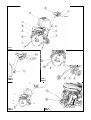
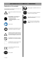
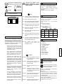
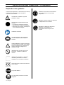
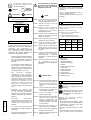
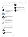
EN
Operator’s manual
FR
Manuel d’utilisation et d’entretien
ES
Manual de explicaciones
FS305
FS309
HUSQVARNA CONSTRUCTION PRODUCTS
DECLARATION
DE
CONFORMITE
DIRECTIVES EUROPEENNES
AUX
HUSQVARNA CONSTRUCTION PRODUCTS, 433 81
Gothenburg, Sweden, déclare que la machine FS305, FS309
est conforme aux dispositions des DIRECTIVES :
•
•
•
•
•
"MACHINES" modifiées (89/392/CEE)
"BASSE TENSION" modifiées (73/23/CEE)
"CEM” (89/336/CEE)
”BRUITS” (2000/14/CEE)
” DECHETS
D’EQUIPEMENTS
ELECTRIQUES
ELECTRONIQUES (DEEE) ” (2002/96/CE)
EG-RICHTLIENIEN
ERKLÄRUNG
WITH
HUSQVARNA CONSTRUCTION PRODUCTS, 433 81
Gothenburg, Sweden, herewith declares that the machine
FS305, FS309 conforms to the DIRECTIVES :
•
•
•
•
•
"MACHINES" modified (89/392/CEE)
"LOW VOLTAGE" modified (73/23/CEE)
"EMC” (89/336/CEE)
”NOISE” (2000/14/CEE)
” WASTE ELECTRICAL AND ELECTRNIC EQUIPEMENT
(WEEE) ” (2002/96/EC)
KONFORMITÄTS-
DECLARACIÓN DE CONFORMIDAD CON LAS
DIRECTIVAS EUROPEAS
HUSQVARNA CONSTRUCTION PRODUCTS, 433 81
Gothenburg, Sweden, erklärt hiermit, daß die machine
FS305, FS309 konform ist, mit der :
HUSQVARNA CONSTRUCTION PRODUCTS, 433 81
Gothenburg, Sweden, dclara que la máquina FS305, FS309
es conforme a las disposiciones de las DIRECTIVAS :
•
•
•
•
•
–
ET
DECLARATION
OF
CONFORMITY
EUROPEAN DIRECTIVES
"MACHINENBAURICHTLINIE" in Änderungs-fassung
(89/392/CEE)
"NIEDERSPANNUNGSRICHTLINIE"
in
Änderungsfassung (73/23/CEE)
Linie
"ELEKTROMAGNETISCHESTÖR-SICHERHEIT”
(89/336/CEE)
”LÄRMSCHUTZRICHTLINIE” (2000/14/CEE)
” ELEKTRO-UND ELEKTRONIK-ALTQERATE“(2002/96/EG)
DICHIARAZIONE DI
DIRETTIVE EUROPEE
"MÁQUINAS" modifiées (89/392/CEE)
"BAJA TENSION" modifiées (73/23/CEE)
"CEM” (89/336/CEE)
”RUIDOS” (2000/14/CEE)
”RESIDUOS
DE
APARATOS
ELECTRICOS
ELECTRONICOS” (2002/96/CE)
Y
ALLE
VERKLARING VAN CONFORMITEIT MET DE
EUROPESE RICHTLIJNEN:
HUSQVARNA CONSTRUCTION PRODUCTS, 433 81
Gothenburg, Sweden, dichiara che la macchina FS305,
FS309 est conforme e conforme alle disposizioni della
DIRETTIVA :
HUSQVARNA CONSTRUCTION PRODUCTS, 433 81
Gothenburg, Sweden, verklaart dat de machine FS305,
FS309 voldoet aan de eisen van de volgende
RICHTLIJNEN:
•
•
•
•
•
CONFORMITA'
•
•
•
•
•
"MACCHINE" modificata (89/392/CEE)
"BASSA TENSIONE" modificata (73/23/CEE)
"CEM” (89/336/CEE)
”RUMORI” (2000/14/CEE)
”DI
APPARECCHIATURE
ELETTRICHE
ELETTRONICHE (RAEE) ” (2002/96/CE)
ED
•
•
•
•
•
"MACHINES", gewijzigd (89/392/EEC)
"LAAGSPANNING", gewijzigd (73/23/EEC)
"CEM” (89/336/EEC)
”GELUID” (2000/14/EEC)
” AFGEDANKTE ELEKTRISCHE EN ELEKTRONISCHE
APPARATUUR (AEEA) ” (2002/96/EG)
FÖRSÄKRAN
OM
ÖVERENSSTÄMMELSE
ENLIGT EU-DIREKTIVEN:
DECLARAÇÃO DE CONFORMIDADE COM AS
DIRECTIVAS EUROPEIAS:
HUSQVARNA CONSTRUCTION PRODUCTS, 433 81
Gothenburg, Sweden, intygar härmed att maskinen FS305,
FS309 uppfyller villkoren i följande DIREKTIV:
HUSQVARNA CONSTRUCTION PRODUCTS, 433 81
Gothenburg, Sweden, declara que a máquina FS305, FS309
está em conformidade com as disposições das
DIRECTIVAS:
•
•
•
•
•
"MASKINER" och senare ändringar (89/392/CEE)
"LÅGSPÄNNINGAR" och senare ändringar (73/23/CEE)
"ELEKTROMAGNETISK
KOMPATIBILITET"
(89/336/CEE)
"BULLER" (2000/14/CEE)
”ELEKTRISKA
ELLER
ELEKTRONISKA
PRODUKTER
(WEEE) ” (2002/96/EG)
•
•
•
•
•
"MÁQUINAS" modificadas (89/392/CEE)
"BAIXA TENSÃO" modificadas (73/23/CEE)
"CEM” (89/336/CEE)
”RUÍDOS” (2000/14/CEE)
” RESIDUOS DE EQUIPAMENTOS ELECTRICOS
ELECTRONICOS (REEE) ” (2002/96/CE)
Christer Carlberg, Operations Manager
Husqvarna Construction Products
E
FIG. 1
ABB. 1
FIG. 2
ABB. 2
FIG. 4
ABB. 4
FIG. 3
ABB. 3
FIG. 5
ABB. 5
EXPLANATION OF SYMBOLS – WARNINGS
Explanation of the symbols
Safety goggles or eyeshade must be worn.
Use of pictograms on the machines (in color) and in the
manual indicate safety warnings
WATCH OUT! DANGER! General danger
signal.
REQUIREMENT. The following must
always be used with the machine:
• certified safety helmet
• certified ear protection
• certified safety goggles or certified
eyeshade.
Loud noise in environment as defined by
European Community directive.
Disk rotation must stop when moving the
machine at the work site.
Disk must be removed during slinging,
loading, unloading and transport at the
worksite.
Read manual.
Carefully READ and assimilate the user’s
manual before operating the machine.
WARNING. Triangle and black marking on
yellow background. Danger if instructions
are ignored. Risk of injury to user or third
party. Risk of damage to machine or tool.
PROHIBITED. Red circle with or without
diagonal bar. Use or presence forbidden.
INFORMATION or specific instructions on
how to use or check the machine.
This machine complies with the EC
directive in force.
STOP symbol.
6 - English
This symbol indicates that the
machine is in conformance with
the applicable European directive.
MANDATORY
INDICATION
INFORMATION
INSTRUCTION
WARNING
PROHIBITION
FAILURE TO COMPLY WITH
THESE WARNINGS COULD
RESULT IN DEATH OR SERIOUS
BODILY INJURY.
DO carefully read and understand all the
instructions before operating the saw.
MANUFACTURER
N° SERIE
SERIAL
FABRICATION
YEAR
ANNEE DE
FABRICATION
WEIGHT
MASSE UTILE
Kg
MAXI TOOL
Ø MAXI OUTIL.
mm
PLAGE DE
TENSION
BORE
Ø ALESAGE
mm
FREQUENCE
SPEED
T/MN - RPM
PUISSANCE
INT. UTIL.
kW
V
Hz
A
• Utilisation : sawing with sprinkling of
fresh, old or coated (asphalt) concrete.
DO
Instruction plate
TYPE
Use
• T o o l s : Water-cooled diamondimpregnated discs - Øx350 mm - bore
25.4 mm.
(Details from your usual supplier).
These signs give advice
concerning your safety
TYPE
1
FREQUENCY
INTENSITY
Technical specifications
• Depth of cut : Ø 350: 120 mm
DO always keep all guards in place.
• Nominal weight (unladen) : 48 to 52 kg
(depending on version)
DO aways wear safety approved hearing,
eye, head and respiratory protection.
• Service weight : 52 to 70 kg (including
tank)
POWER
VOLTAGE
2
DO keep all parts of your body away from
the blade and all other moving parts.
DO know how to stop the saw quickly in
case of an emergency.
• Dimensions (LxWxH) :
- 860 x 505 x 990 mm
• Speed of spindle rotation :
- 2450-2680 rpm
(depending on version)
POWER
LEVEL
PRESSURE
LEVEL
VIBRATION
LEVEL
Lwa (dB)
EN ISO 3744
Lpa (dB)
EN ISO 4871
G ENV
25349
HONDA
GX160
108
84
1.3
ROBIN
EY20
102
88
1.3
MODEL
DO shut off the engine and allow it to cool
before refueling.
DO inspect the blade, flanges and shafts
for damage before installing the
blade.
SPECIAL INSTRUCTIONS
DO use caution and follow the
instructions when loading and
unloading the saw.
• Perfect technical condition (use for
the purpose for which it is intended
and taking into account any risks, and
correction of any malfunction
detrimental to safety).
• Use a diamond disk for cutting with
water (sawing new or old concrete,
tarmac or asphalt). No other type of
disk is allowed (abrasive, saw, etc...).
• Competent staff (qualifications, age,
training) who have read and
understood the manual in detail
before starting work: any electrical,
mechanical or other problem should
be investigated by a qualified
maintenance engineer (electrician,
maintenance manager, approved
dealer, etc . . .).
3
11.
12.
13.
14.
15.
16.
17.
18.
19.
10.
11.
12.
Description of the machine [FIG. 1]
Handle
Motor stop
Lowering handwheel
Graduated scale
Engine
Engine oil drain
Front guide
Belt cover
Disk casing
Service spanner
Water intake tap
Tank (17 litres)
English
The disc cutter is designed to provide safe
and reliable service in operating conditions
corresponding with the instructions, but it
can present dangers for the user and risks
of damage, consequently regular on site
inspection is necessary to ensure :
DO use only blades marked with a
maximum operating speed greater
than the blade shaft speed.
DO NOT
DO NOT
allow other persons to be near
the saw when starting, refueling
or when cutting.
4
Handling - Transport
DO NOT
operate gasoline engines in an
enclosed area unless it is
properly vented.
Switch off the disk prior to moving
the machine on jobsite.
DO NOT
use damaged equipment or
blades.
Remove the disk prior to hoisting,
loading, unloading and transporting
the machine on jobsite.
DO NOT
operate the saw in areas of
combustible material. Sparks
from the saw could cause a fire
or an explosion.
Height of adjustable
(unscrew the lever (M))
[ SEE FIG. 2].
DO NOT
allow blade exposure from the
guard to be over 180 degrees.
• The ground-saw only needs pushing to
move it into position on the site. It is easy
to move on its four wheels, without
starting the motor.
• Respect of the maintenance intervals
and periodical checks recommended.
DO NOT
leave the saw unattended with
the motor running.
• The handwheel (K) locks the machine
itself in the high position.
• That only genuine spare parts are
used for repairs.
DO NOT
operate the saw while under the
influence of drugs or alcohol.
• That the warnings and instructions
marked on the machine are followed
(adequate personal protection,
correct use, general safety
instructions, etc).
• That no modification, transformation
or addition is detrimental to safety
and that it is carried out without prior
authorization from the manufacturer.
handlebars
• Light weight, compact, transportable in a
vehicle by one person.
7
5
Check before starting
• Firmly tighten the screw (D) with the
spanner provided with the machine,
holding the disc steady by hand.
Please read the instructions for
use prior to operating the
machine for the first time.
• Replace the protective guard (if this is not
replaced the casing safety switch will
prevent the saw being started).
Motor off.
• Reconnect the water hose (mains with
valve or tank).
The working area must be
completely cleared, well lit and
all safety hazards removed (no
water or dangerous objects in
the vicinity)
• Tighten the nut (E).
The holding screw (D) of the disc
has a right-hand thread.
8
Stopping the machine
Motor off
• Turn the handwheel (K) to free the
disk from the groove [ SEE FIG. 4]
.
• No need to lock the saw up by
releasing the handwheel (K).
• Turn off the water supply (G).
• Allow the motor to run idle.
• Switch off the motor (refere to the motor
maintenance manual).
The operator must wear
protective
clothing
appropriate to the work he
is doing. We recommend
that this includes both eye
and ear protection
Emergency stop
Operate the switch (J) in front
of the engine.
The use of ear protection is
mandatory.
Any persons not involved in the
work should leave the working
area
Use only blades marked with a
maximum operating speed
greater than blade shaft speed
9
7
Always pay extreme care and
attention to the preparation of
the machine before starting up
Take into account the working
conditions from health and safety
point of wiew.
• Model with petrol motor (refer to the
motor maintenance manual).
■ Make sure the fuel is topped up.
■ Check the oil level; as the motor often
English
works at an angle, check it frequently in
the horizontal position that the oil level
is never below the second line on the
gauge.
■ To start up, refer to the motor
instructions.
Remove all adjustment tools and
wrenches from floor and
machine
Always keep blade guard in
place
Fitting the blade
• Place the machine in an high position.
• Make sure the engine is switched off.
.
• Unscrew the nuts (E) from the guard
housing [ SEE FIG. 3].
• Remove the guard housing (A).
• Fit the diamond impregnated disc.
8
Note the direction of rotation
indicated by an arrow on one
side of the disc (direction of
rotation shown on the outside of
the guard housing).
Check the state of cleanliness of
the disc support faces of the
adaptor plates (B and C) and of
the spindle.
• In all case, disengage the disc from the
groove and give the machine a complete
check-over.
Entrust repairs to authorised
dealer only
• Mark out a line on the ground where a cut
has to be made.
• Position the machine so that the lowered
front guide (F) and the disc are aligned
with the line marked out (disc visble on
the belt side of the housing).
• Allow the motor to warm up.
• Turn on the water supply tap (G) (from
the mains or the water tank).
Motor off
• There may be several causes responsible
for arresting the disc in the sawing groove
or stopping the machine:
■ Belt tension.
■ Lack of fuel.
■ Advance or lowering too fast, etc.
• Turn off the water tap (G) (from the mains
or from the tank in order to fill it) [ SEE
FIG.x4].
• Start up the motor : refer to the motor
manufacturer’s instructions in the service
manual.
6
Incidents during sawing
Starting up
10
Maintenance (with the
engine stopped)
"Engine Maintenance" : refer to
the engine maintenance booklet.
• After use, clean the machine.
• Increase the motor speed to full.
• Hold the saw, turn the handwheel (K)
and position the disk in contact with the
floor.
• Lower to the depth of cut required, and
bearing in mind that each graduation of
the scale corresponds to a depth of 1cm.
Lower slowly to prevent the engine
stalling.
• Gently move the machine forward
ensuring that the front guide and the disc
are always aligned with the line marked
out.
• Lubrication : apply a moderate amount of
bearing lubricant to the nipples in the
depth adjustment chassis (depending on
the frequency of use).
OIL
• Check the engine oil everyday. Refer to
the engine manual for oil change
schedule. Use :
■ SAE 10W30 motor oil with API class
MS, SD, SE or better for PETROL
engines.
■ API class CD or CE for Hatz diesel.
Ensure that the water supply is
abundant, when cutting wet.
Dispose of the old oil as laid
down by the regulations in force.
• To change the oil, remove the disk, lower
the saw to the lowest position and then
place the tray by the drain outlet (L) [SEE
FIG. 4].
Store in a safe place, out of
reach of children
Maintain tools carefully
12
Important advice
13
• Periodically, tighten the nuts and bolts
and particularly after the first few hours of
use.
Repairs
S
A
V
• Check belt tensions, tighten them without
overdoing it.
We carry out all repairs in the
shortest possible time and at the
most economical prices (see
overleaf for our address).
• When garaged, it is recommended the
disc be removed and suitably stored.
AIR FILTER
• Make sure the disc is correctly tightened.
• Read engine owners manual for
maintenance intervals. For extremely
dusty conditions you may have to clean
the air filter element 2 to 3 times a day.
• Make sure the disc supports surfaces, the
adaptor plates and the spindle are kept
clean.
• Replace any damaged filters or gaskets.
Store in a safe place out ot reach
of children.
Remove all adjustment tools and
wrenches
Store diamond tool in a safe
place so it cannot be bent or
damaged.
The manufacturer declines all
responsibility for loss or damage
resulting from misuse or any
modification, alteration or
powering that does not conform
to the manufacturer's original
specifications.
At the work station, the sound
pressure level may exceed
85xdbx(A)
14
Spare parts
For quick supply of spare parts and to
avoid any lost time it is essential to quote
the data on the manufacturer's plate fixed
to the machine and the part number of the
part to be replaced with every order.
00000000
(0)
Item number
Quantity
See exploded view
In this case individual protection
measures must be taken.
Engine belt tension
It may be necessary after using a few times
to retension the belts, without overtightening them. To do this :
• loosen the 2 nuts (S) fixing the motor to
the chassis, without removing them
[ SEE FIG. 5];
• tighten the tensioning nuts (N), these
screws pull the motor up.
.
15
Scrapping
In the event of deterioration and
scrapping of the machine, the
following items must be
disposed of in accordance with
the requirements of the
legislation in force.
• Main materials :
• Motor : Aluminium (AL), Steel (AC),
Motor : Copper (CU), Polyamide (PA)
• Machine : Steel sheet (AC),
■ Machine : Cast iron (FT)
■ Machine : Aluminium (AL)
• at normal tension, tighten the motor
fixing nuts (S).
The instructions for use and spare parts
found in this document are for information
only and are not binding.
As part of our product quality improvement
policy, we reserve the right to make any
and all technical modifications without prior
notice.
English
11
When working in a limited or
closed area, make sure that the
ventilation is adequate. The
exhaust gases contain carbon
monoxide (exposure to this toxic
gas can cause loss of
consciousness and can be fatal).
9
EXPLICATION DES SYMBOLES – CONSIGNES
Explication des symboles
L'emploi de pictogrammes sur les machines (en couleur)
et dans le manuel indiqueront des conseils qui
concernent votre sécurité.
Emissions sonores dans l’environnement
selon la directive de la Communauté
européenne.
ATTENTION ! DANGER ! Symbole
général de danger.
Obligation d'arrêt de rotation du disque lors
du déplacement sur le chantier.
OBLIGATION. Toujours utiliser avec la
machine :
• un casque de protection homologué
• des protections d’oreilles homologuées
• des lunettes de protection homologuées
ou une visière homologuée.
Veuillez lire le manuel.
LIRE attentivement et bien assimiler le
manuel d’utilisation avant d’utiliser la
machine.
AVERTISSEMENT. Triangle et marquage
noir sur fond jaune : danger si non respect.
Risque de blessures pour l’utilisateur ou
des tiers. Risques de dégâts sur la
machine ou l’outil.
INTERDICTION. Cercle rouge avec ou
sans barre : utilisation ou présence
interdite.
INDICATION. Information – Instruction :
indications particulières concernant
l’utilisation ou le contrôle de la machine.
Cette machine est conforme à la directive
CE en vigueur.
Le symbole ARRET.
Port de lunettes protectrices ou visière
obligatoire.
10 - Français
Obligation de démonter le disque lors
d'élingage, de chargement, de
déchargement et de transport sur le
chantier.
Ce symbole signifie que la
machine est conforme à la
directive européenne.
INDICATION
INFORMATION
INSTRUCTION
OBLIGATION
AVERTISSEMENT
LE NON-RESPECT DE CES MISES
EN GARDE PEUT ENTRAINER LA
MORT OU DES BLESSURES
CORPORELLES GRAVES
INTERDICTION
FAIRE
Ces signes vous indiqueront les conseils
qui concernent votre sécurité
Plaque signalétique
FAIRE toujours maintenir toutes les
protections en place.
LE FABRICANT
TYPE
N° SERIE
ANNEE DE
FABRICATION
MASSE UTILE
Kg
Ø MAXI OUTIL.
mm
PLAGE DE
TENSION
Ø ALESAGE
mm
FREQUENCE
T/MN - RPM
PUISSANCE
INT. UTIL.
FAIRE lire attentivement et bien vérifier
que l'on a compris toutes les
instructions avant d'utiliser la scie.
kW
V
Hz
A
FAIRE toujours porter les sécurités
auditives et/ou occulaires, le
protège-tête et la protection
respiratoire approuvés.
FAIRE toujours se tenir à distance du
disque et de toutes les autres
pièces en mouvement.
FAIRE savoir comment arrêter la scie
rapidement en cas d'urgence.
CONSIGNES PARTICULIERES
Conçue pour assurer un service sûr et
fiable dans des conditions d'utilisation
conformes
aux
instructions,
la
tronçonneuse peut présenter des dangers
pour l'utilisateur et des risques de
détérioration, des contrôles réguliers sur le
chantier sont nécessaires, s'assurer :
• de l'état technique parfait (utilisation
suivant affectation en tenant compte
des risques éventuels, suppression
de toute malfonction nuisible à la
sécurité),
• de l'usage d'un disque diamant pour
tronçonnage à l'eau (sciage des
bétons frais ou anciens et enrobés,
asphalte), utilisation interdite de tout
autre disque (abrasif, scie, etc...),
• d'un
personnel
compétent
(qualification, âge, formation,
instruction) ayant pris connaissance
dans le détail du manuel avant de
commencer le travail ; toute anomalie
électrique, mécanique ou d'autre
origine sera contrôlée par une
personne habilitée à intervenir
(électricien,
responsable
de
l'entretien, agent revendeur agréé,
etc...),
Français
• s'assurer
du
respect
des
avertissements et directives marqués
sur la machine (protections
adéquates personnelles), utilisation
conforme, instructions de sécurité en
général...),
11
• qu'aucune
modification,
transformation ou complément soit
nuisible à la sécurité et ne sera pas
réalisée sans l'autorisation du
fabricant,
• du respect des fréquences de
vérifications et contrôles périodiques
préconisés,
• de la garantie de pièces de rechange
d'origine lors de réparations.
1
Emploi
• Utilisation : sciage avec arrosage des
bétons frais ou anciens et enrobés
(asphalte).
• Outils : Disques Diamantés à Eau - Ø
350xmm - alésage 25,4 mm.
(Renseignements auprès du fournisseur
habituel).
2
Caractéristiques techniques
• Profondeur de coupe : Ø 350 : 120 mm
• Masse nominale (à vide) : 48 à 52 kg
(selon version)
• Masse en service : 52 à 70 kg
• Dimensions (L x l x H)(Emballage) :
- 860 x 505 x 990 mm
• Vitesse de rotation de la broche :
- 2450 - 2680 tr/mn (selon version)
PUISSANCE
ACOUSTIQUE
PRESSION
ACOUSTIQUE
NIVEAU DE
VIBRATION
Lwa (dB)
EN ISO 3744
Lpa (dB)
EN ISO 4871
G ENV
25349
HONDA
GX160
108
84
1.3
ROBIN
EY20
102
88
1.3
MODELE
FAIRE couper le moteur et le laisser
refroidir avant de refaire le plein.
FAIRE vérifier le disque, les brides et les
arbres afin de voir s'ils ne sont
pas endommagés avant d'installer
le disque.
FAIRE n'utiliser que des disques portant
l'indication d'une vitesse de
fonctionnement
maximale
supérieure à la vitesse de l'arbre
de disque.
FAIRE preuve de prudence et respecter
les
instructions
lors
du
chargement et du déchargement
de la scie.
NE PAS FAIRE
NE PAS permettre à d'autres personnes
de se trouver à proximité de sa
mise en service, du plein en
carburant ou des travaux de
coupe.
NE PAS faire fonctionner des moteurs à
essence dans un espace clos,
sauf ventilation appropriée.
NE PAS utiliser un matériel ou des
disques endommagés.
NE PAS faire fonctionner la scie dans des
espaces où se trouvent des
produits combustibles. Les
étincelles projetées par la scie
peuvent provoquer un incendie
ou une explosion.
NE PAS autoriser une protection du
disque inférieure à 180 degrés.
NE PAS laisser la scie sans surveillance
alors que le moteur tourne.
NE PAS utiliser la scie sous l'influence de
drogue ou d'alcool.
3
Description de la machine [FIG. 1]
11. Brancard
12. Stop moteur
13. Volant de plongée
14. Indicateur de plongée
15. Moteur
16. Sortie de vidange moteur
17. Guide avant
18. Carter de courroie
19. Carter de disque
10. Clé de service
11. Robinet d'arrivée d'eau
12. Réservoir (17 L)
4
Manutention - Transport
Obligation d'arrêt de rotation du
disque lors du déplacement sur le
chantier.
Obligation de démonter le disque
lors d'élingage, de chargement, de
déchargement et de transport sur
le chantier.
Hauteur
du
brancard
(desserrage des leviers (M))
[ VOIR FIG. 2].
réglable
• Pour la mise en place sur chantier, il suffit
de pousser la scie à sols. Elle se déplace
facilement sur ses quatre roues, sans
mise en route du moteur.
• Blocage en position haute par le volant
(K).
• D'un poids léger, compacte, transportable
dans un véhicule par une personne.
5
Vérification avant mise en service
Avant toute mise en service, lire
attentivement la notice, et se
familiariser avec la machine.
• Bloquer fermement la vis (D) à l'aide de
la clé fournie avec la machine en
immobilisant le disque avec la main.
• Remettre le carter de protection
(obligatoire pour la sécurité carter, sinon
démarrage impossible).
• Raccorder le flexible à eau (réseau avec
vanne ou réservoir).
Arrêt moteur
Le champ de travail doit être
parfaitement en ordre, bien éclairé,
et ne doit présenter aucun risque
(ni-humidité, ni produits dangereux
à proximité).
• Serrer les écrous (E).
La vis de serrage (D) du disque
possède un filetage avec un pas
à droite
L'opérateur doit porter des
protections appropriées au
travail.
Obligation
antibruit.
port
du
8
Arrêt
Arrêt moteur.
• Manoeuvrer le volant de plongée (K), pour
dégager le disque de la rainure [ VOIR
FIG.x4].
• Aucun blocage n'est nécessaire, la machine reste en position haute.
• Fermer l'arrivée d'eau (G).
• Laisser tourner le moteur au ralenti.
• Arrêter le moteur (se reporter au livret
d'entretien moteur).
L'interrupteur (J) se trouve à
l'avant droit de la machine,
sur le moteur thermique.
casque
Toute personne étrangère doit être
écartée du champ de travail.
N'utiliser que des disques
marqués d'une vitesse maximale
de travail supérieure à la vitesse
effective de la broche
9
7
Mise en service
Rester toujours attentif.
Tenir compte des conditions
ambiantes (santé et sécurité).
• Machine à moteur essence (se reporter
au livret d'entretien moteur)
■ S'assurer du plein de carburant.
Avant la mise en service, enlever
les clés et outils de réglage du
sol ou de la machine.
Incident en cours de sciage
• Plusieurs causes peuvent être
responsables de l'arrêt du disque dans la
rainure de sciage ou de la machine :
■ Tension des courroies,
■ Défaut de carburant,
■ Avance ou plongée trop rapide, etc.
• Dans tous les cas, dégager le disque de
la rainure et faire un contrôle complet de
la machine.
Maintenir le carter de protection
en place pendant toute la durée
du travail.
Faire réparer par une personne
qualifiée.
■ Vérifier le niveau d'huile: le moteur
■ Pour le démarrage, se reporter à la
notice des moteurs.
• Fermer le robinet d'eau (G) (du réseau ou
du réservoir pour le remplir) [ VOIR
FIG.x4].
• Tirer "au bleu" un trait sur le sol, à
l'emplacement à tronçonner.
• Positionner la machine de telle façon que
le guide avant rabattu (F) et le disque
coïncident avec le tracé (disque visible
côté carter de courroies).
• Procéder à la mise en marche du moteur:
se reporter aux instructions du manuel de
service du constructeur.
6
Montage du disque
• Laisser chauffer le moteur.
• Ouvrir le robinet d'arrivée d'eau (G) (du
réseau ou du réservoir).
Arrêt moteur
• Mettre la machine en position haute.
• S'assurer que le moteur est bien à
l'arrêt (Bouton stop (J) en position "O").
• Desserrer les écrous (E) du carter
[VOIR FIG.x3].
• Basculer la partie avant du carter (A).
• Monter le disque diamanté.
• Augmenter la vitesse du moteur à plein
régime.
• Maintenir la machine, actionner le volant
(K) et amener le disque en contact avec
le sol.
• Procéder à la descente jusqu'à la
profondeur de coupe désirée à l'aide du
volant. Sur l'indicateur de plongée, une
graduation correspond à une plongée
de 1cm. Une descente lente est conseillée
pour éviter de caler le moteur.
Tenir compte de son sens de
rotation repéré par une flèche
sur l'une de ses faces (sens de
rotation sur le flanc droit du
carter).
• Faire avancer doucement la machine en
s'assurant que le guide avant et le disque
coïncident toujours bien avec le tracé.
Vérifier l'état de propreté des
faces d'appui du disque, des
flasques (B et C) et de la broche.
Arrosage abondant =
longévité assurée du disque
10
Entretien (arrêt obligatoire du moteur)
"Entretien moteur" : se reporter
au livret d'entretien moteur.
• Après chaque usage, nettoyer la
machine.
• Graissage : alimenter modérément les
graisseurs du châssis de réglage de
profondeur avec de la graisse à
roulement (suivant la fréquence
d'utilisation).
HUILE
• Vérifier l'huile moteur quotidiennement.
Se référer au manuel du moteur pour les
intervalles de remplacement de l'huile.
Utiliser :
• Une huile moteur SAE 10W30 avec
classe API MS, SD, SE ou supérieure
pour les moteurs à essence.
• Une huile classe API CD ou CE pour
les moteurs diesels.
Le lubrifiant sera éliminé
conformément aux modalités
prescrites par la législation en
vigueur.
Français
travaillant souvent incliné, vérifier
fréquemment, en position horizontale,
que son niveau d'huile ne soit jamais
inférieur au deuxième trait de la jauge.
12
• Pour vidanger le moteur, démonter le
disque, descendre la machine en position
basse maximum, puis présenter le bac à
la sortie de vidange (L) [ VOIR FIG. 4].
Stocker dans un endroit sûr,
hors de portée des enfants
Entretenir soigneusement les
outils
12
Recommandations importantes
• Périodiquement, resserrer la boulonnerie,
et tout spécialement après les premières
heures de fonctionnement.
• Effectuer un serrage correct du disque.
• Veiller à la propreté des surfaces d'appui
du disque, des flasques et de la broche.
11
Tension de la courroie moteur
Après quelque temps d'utilisation, il peut
être nécessaire de retendre, sans
exagération, les courroies. Pour cela :
■ Débloquer les 2 écrous (S) fixant le
moteur au châssis, sans les enlever
[ VOIR FIG. 5].
■ Visser les écrous de tension (N), ces
écrous poussent le moteur vers le haut.
Vous adresser à votre fournisseur
qui est à votre entière disposition
pour vous assurer toute réparation
dans les délais les plus réduits et
aux meilleurs prix.
• En position garage, il est recommandé
d'enlever le disque et de le stocker
convenablement.
• Se référer au manuel du moteur pour les
intervalles d'entretien. Pour des
conditions extrêmement poussiéreuses, il
faudra parfois nettoyer l'élément filtrant 2
à 3 fois par jour.
Remiser les produits dans un
endroit sûr, hors de portée des
enfants.
Enlever tous les outils de
réglage et les clés.
Remiser l'outil diamanté à un
endroit où il ne pourra pas être
faussé ou endommagé.
Réparation
S
A
V
• Vérifier la tension des courroies, les
tendre sans exagération.
FILTRE A AIR
• Remplacer tous les filtres ou garnitures
d'étanchéité endommagés.
13
Le fabricant décline toute
responsabilité résultant d'un
emploi inadapté, de toute
modification, adaptation ou
motorisation non conforme à la
définition d'origine prévue par le
constructeur.
14
Pour une livraison rapide des pièces de
rechange et afin d'éviter toute perte de temps,
il est nécessaire de rappeler à votre
fournisseur lors de chaque commande les
indications qui figurent sur la plaque
signalétique de la machine, ainsi que la
référence de la pièce à remplacer.
00000000
Au poste de travail, la puissance
sonore peut dépasser 85 db (A).
Dans ce cas, des mesures
individuelles de protection
doivent être prises.
Dans le cas de travail dans un
endroit restreint ou fermé,
assurez-vous d'une ventilation
adéquate,
les
gaz
d'échappement contenant de
l'oxyde de carbone (une
exposition à ce gaz toxique peut
provoquer une perte de
conscience et être mortelle).
Pièces de rechange
(0)
Code
Quantité
Voir vue éclatée
15
Mise au rebut
En cas de détérioration et de casse
de la machine, ceux-ci seront
éliminés conformément aux
modalités prescrites par la
législation en vigueur.
• Matériaux principaux :
• Moteur : Aluminium (AL) - Acier (AC)
n Moteur : Cuivre (CU) - Polyamide (PA)
• Machine : Tôle acier (AC) - Fonte (FT)
n Machine : Aluminium (AL)
■ A tension normale, bloquer les écrous
Français
de serrage (S) du moteur.
13
Les conseils d'utilisation et pièces détachées
figurant sur ce document sont donnés à titre
d'information et non d'engagement.
Soucieux de la qualité de nos produits, nous nous
réservons le droit d'effectuer, sans préavis, toutes
modifications techniques en vue de leur
amélioration.
EXPLICACIÓN DE LOS SÍMBOLOS – CONSIGNAS
Explicación de los símbolos
Emisiones sonoras en el entorno según la
directiva de la Comunidad Europea.
El empleo de pictogramas en las máquinas (de color) y
el manual indicarán consejos relativos a la seguridad.
¡ATENCIÓN! ¡PELIGRO! Símbolo general
de peligro.
OBLIGACIÓN. Utilizar siempre con la
máquina:
• un casco de protección homologado
• protecciones auriculares homologadas
• gafas protectoras homologadas o una
visera homologada.
Lea el manual
LEER atentamente y comprender bien el
manual de utilización antes de usar la
máquina.
ADVERTENCIA. Triángulo y marcado
negro en fondo amarillo: peligro si no se
respeta. Riesgo de herida para el usuario o
algún tercero. Riesgos de daños en la
máquina o la herramienta.
PROHIBICIÓN. Círculo rojo con o sin
barra: utilización o presencia prohibida.
INDICACIÓN. Información – Instrucción:
indicaciones especiales relativas a la
utilización o el control de la máquina.
Esta máquina está en conformidad con la
directiva CE vigente.
Símbolo PARADA.
Obligación llevar gafas protectoras o
visera.
14 - Español
Obligación detener la rotación del disco
durante el desplazamiento en la obra.
Obligación de desmontar el disco en caso
de eslingado, carga, descarga y transporte
en la obra.
5
Verificación antes de la
puesta en marcha
• Mantener el disco inmóvil con la mano y
apretar bien el tornillo (D) utilizando la
llave suministrada con la máquina.
Antes de la puesta en marcha, leer
detenidamente las instrucciones y
familiarizarse con la máquina.
• Poner el cárter de protección (obligatorio
para la seguridad cárter; de lo contrario el
arranque es imposible).
Parada del motor.
• Conectar la manguera de agua (grifo de
distribución o depósito).
• Apretar la tuerca (E).
El campo de trabajo debe estar
perfectamente en orden, bien
iluminado y no debe presentar
ningún riesgo o peligro. (Ni
humedad,
ni
productos
peligrosos cerca)
El tornillo de sujeción (D) del
disco tiene rosca a derechas.
8
Parada
Parada del motor.
• Levantar la perilla (K) y tirar hacia sí
para liberar el disco de la ranura [ VEASE
FIG. 4].
• Bloquear la máquina en posición alta
soltando la palanca (K).
• Cierre la alimentación de agua (G).
• Deje funcionar el motor en régimen
mínimo.
• Pare el motor (véase el folleto de
instrucciones de mantenimiento).
Llevar las protecciones
propias de su trabajo
Parada de urgencia
Bascular el interruptor (J)
.
Es obligatorio el uso del caso
antiruidos.
Alejar a toda persona, ajena a la
obra.
Usar unicamente discos con una
velocidad norminal superior a la
del eje del disco.
9
7
Puesta en marcha
Este siempre atento
• Máquina con motor de gasolina (véase
el folleto de mantenimiento del motor).
• Comprobar si el depósito de
combustible está lleno.
• Medir el nivel de aceite. Como el motor
funciona a menudo inclinado,
asegurarse frecuentemente de que el
aceite alcanza como mínimo la
segunda marca de la varilla.
• Véase el folleto de instrucciones de
cada motor para la puesta en marcha.
Antes de la puesta en marcha,
quitar las llaves y útiles de
reglaje
Montaje del disco
• Ponga la máquina en posición alta.
• Comprobar si pare el motor.
.
• Afloje las tuercas (E) del cárter
[VEASE FIG.x3].
• Retire el cárter (A).
• Monte el disco de diamante.
Reparar la máquina por una
persona cualificada
• Cierre el grifo de agua (G) (distribución o
para llenar el depósito) [VEASE FIG. 4].
• Haga un trazo en el suelo donde debe
cortar.
• Coloque la máquina en la posición
apropiada: con la guía frontal (F) y el
disco sobre el trazo (disco visible por el
cárter de las correas).
• Deje calentar el motor.
• Abra el grifo de aspersión de agua (G)
(distribución o depósito).
Parada del motor.
• En este caso, retire el disco de la ranura
y haga una inspección completa de la
máquina.
Tener siempre colocados los
protectores
• Ponga el motor en marcha de acuerdo
con las instrucciones de servicio del
fabricante.
6
• Algunas irregularidades pueden provocar
el bloqueo de la máquina o del disco en la
ranura :
• Tensión de las correas.
• Falta de combustible.
• Velocidad excesiva de penetración o
avance, etc..
• Acelere el motor a régimen máximo.
• Sujetar la máquina, levantar la perilla
(K) con el pie y desplazar el disco hasta
que se ponga en contacto con el suelo.
• Efectuar la bajada hasta la profundidad
de corte deseada (hasta escuchar un
clic), teniendo en cuenta que cada
muesca de la perilla corresponde a una
profundidad de 1 cm. Se recomienda
proceder lentamente para evitar que el
motor se cale.
Montar el disco de modo que la
flecha de dirección de rotación
(en una cara del disco) coincida
con la flecha en el costado
derecho del cárter.
• Haga avanzar la máquina lentamente,
manteniendo el disco y la guía frontal
sobre el trazo de corte.
Comprobar si las superficies de
contacto del disco, de los
soportes (B y C) y del eje están
limpias.
La duración de su disco dependera
mucho de su refrigeración que
debe ser muy abundante
10
Mantenimiento
"Mantenimiento
motor":
remitirse
al
manual
de
mantenimiento del motor.
• Consiste principalmente en un limpiado
de la máquina después de cada uso.
• Engrase : alimentar con moderación los
engrasadores del chasis de ajuste de
profundidad con grasa para rodamientos
(según la frecuencia de utilización).
Español
Tome en cuenta las condiciones de
trabajo desde el punto de vista de la
salud la seguridad.
Incidentes durante el corte
ACEITE
• Verificar el aceite motor diariamente.
Remitirse al manual del motor para los
intervalos de cambio de aceite. Utilizar :
• aceite de motor SAE 10W30 con API
clase MS, SD, SE, o mejor para
motores de GASOLINA.
• API clase CD o CE para motor diesel
Hatz.
El lubricante se eliminará de
conformidad
con
las
modalidades prescritas por la
legislación vigente.
15
• Para vaciar el motor, desmontar el disco,
poner la máquina en la posición baja
máxima y, después, poner el depósito en
la salida de vaciado (L) [ VEASE FIG. 4].
Guardar fuera del alcanze de los
niños
Mantener
cuidadas
herramientas
las
FILTRO DE AIRE
• Lea el manual del usuario para conocer
los intervalos de mantenimiento. Para
condiciones
extremadamente
polvorientas, deberá limpiar el filtro de
aire 2 a 3 veces al dia.
• Reemplace
cualquier
empaquetadura dañada.
filtro
o
Guarde la máqulna en un lugar
seguro y fuera del alcance de
los niños.
Retire todas las herramientas y
llaves de ajuste.
Guarde
la
herramienta
diamantada en un sitio seguro
en donde no pueda curvarse o
dañarse.
11
Tensión de las correas del motor
Tal vez sea necesario tensar nuevamente
las correas, de forma moderada, después
de algún tiempo de trabajo. Siga estas
instrucciones.
• Afloje las 2 tuercas (S) que
aseguran el motor al bastidor (no las
quite) [ VEASE FIG. 5].
• Apriete las tuercas en el tuerca tensor
(N) para tirar el motor hacia atrás.
Recomendaciones importantes
13
• Apretar periódicamente las tuercas y los
tornillos, especialmente después de las
primeras horas de servicio.
Reparaciones
S
A
V
• Comprobar la tensión de las correas y de
ser necesario tensarlas de forma
moderada.
Estamos a su entera disposición
para asegurarle todas las
reparaciones en el plazo más
breve posible, y a los mejores
precios (ver dirección al reverso).
• En posición de inmovilización, se
aconseja desmontar el disco y guardarlo
con las debidas precauciones.
• Apretar correctamente el disco.
• Comprobar si las superficies de contacto
del disco, de los soportes y del eje están
limpias.
El
fabricante
no
se
responsabiliza de los daños
causados en caso de utilización
inadaptada,
modificación,
adaptación o motorización no
conforme a la definición de
origen prevista por el fabricante.
14
Para una entrega rápida de las piezas de
recambio, y con el fin de evitar cualquier
contratiempo, es necesario especificar en
cada pedido las indicaciones que figuran
en la placa que contiene la descripción de
la máquina, aso como la referencia de la
pieza que se va a reemplazar.
00000000
En el puesto de trabajo, el nivel
de intensidad acústica no debe
pasar los 85 db (A).
En este caso, se deberán utilizar
medidas
individuales
de
protección.
En un lugar de trabajo cerrado,
asegurese una ventilación
adecuada, ya que el gas
resultante contiene oxido de
carbono. Una fuerte exposición a
esta gas podría provocar la
pérdida de consciencia e incluso
la muerte.
Piezas de recambio
(0)
Codigo
Cantidad
Ver despiece
15
Desecho
En caso de deterioro y de rotura
de la máquina, ésta deberá ser
eliminada de conformidad con
las modalidades prescritas por
la legislación vigente.
• Materiales principales :
• Motor : Aluminio (AL) - Acero (AC) Motor : Cobre (CU) - Poliamida (PA).
• Máquina : Chapa de acero (AC) Máquina : Fundición (FT) Máquina : Aluminio (AL)
Español
• Después de obtener la tensión
apropiada, apriete las tuercas de
sujeción del motor (S).
12
16
Los consejos de utilización y repuestos que
se encuentran sobre este documento son
dados para su informatión y no como
promesa.
Preocupados por la calidad de nuestros
productos, nos reservamos el derecho de
efectuar, sin previo aviso, todas las
modificaciones tecnicas en fig. de su
mejoramiento.
www.husqvarnacp.com
115 03 83-30
2007-06-15