1
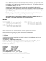
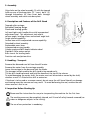
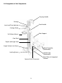
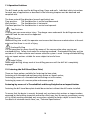
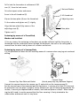
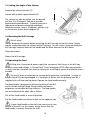
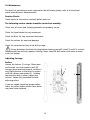
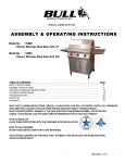
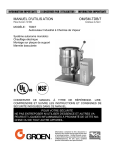
DS160C
Manuel d’utilisation et d’entretien
Foreuse de chantier
Manuale di Istruzioni
Trapanatrice da cantiere
Manual de Instrucciones
Taladradora de obra
Operating Instructions
Drilling Machine
Betriebs-und Wartungsanleitung
Baustellen-Bohrmaschine
Gebruiksaanwijzing
Verplaatsbare Boormachine
Manual de Instrucoes
Perfuradora de obra
Bruksanvisning och Underhallsmanual
Borrmaskin
P/N 541404170
8/2006
1
2
WARNING
Some dust created by power sanding, sawing, grinding, drilling and other
construction activities contains chemicals known to cause cancer, birth defects
or other reproductive harm. Some examples of these chemicals are:
·Lead from lead-base paints,
·Crystalline silica from bricks and cement and other masonry
products and
·Arsenic and Chromium from chemically treated lumber.
Your risk from these exposure varies, depending on how often you do this type
of work. To reduce your exposure to these chemicals: work in a well ventilated
area and work with approved safety equipment, such as those dust masks that
are specially designed to filter out microscopic particles.
·REFER TO MANUAL·
3
PREFACE TO THE MANUAL
These operating instructions apply exclusively to drill stand, type DS 160 C. Please also read
the operating instructions that accompany your drill motor to verify their compatibility and
not to exceed the limitations of the DS 160 C drill stand.
Usage to the Intended Purpose
The drill stand is designed exclusively for core drilling in concrete, asphalt, brickwork or similar
building materials. Details of the maximum permissible drill bit diameter can be found under
“Technical Specifications”. Any use above and beyond the intended purpose endangers both
user and machine and is not permitted.
Before commencing drilling, always ensure that;
there is no danger of drilling through electric cables, gas, oil or other pipes,
the drilled holes do not undermine the stability of the structure,
you do not drill into or through any steel girders,
when drilling through walls, you cannot cause any damage at the drill exit point.
Strict care must be taken when drilling in areas where people or general public
are present. Local codes dictate proper protocol and must be observed.
Improper Usage
The drill stand must not be used for any kind of stirring, e.g. paint or similar;
drilling holes in soil, e.g. to drill holes for posts.
The drill stand must be mounted via anchor bolt or vacuum, do not attempt to
drill hand held or standing on base plate.
This drill stand incorporates the expertise of decades of experience in the field of concrete
drilling.
Before leaving our factory every machine passes an inspection program in which everything is
checked completely.
Following the instructions will ensure that your machine gives long service, in normal
operating conditions.
The user advice and spare parts mentioned in this document are given as an indication and
do not constitute an undertaking. No warranty will be granted in the event of errors or
omissions or for damage occurring during delivery or caused by the design or use of this
machine. We are very concerned about the quality of our products and we serve the right to
make any technical modifications to improve them without warning.
This document will assist the user particularly in:
·Information about the machine
·Information about its possible uses
4
·Prevent accidents due to unsuitable use, by an untrained person, during maintenance,
repairs, overhauls, handling or transport
·Improve the reliability and durability of the machine
·Ensuring correct use, regular maintenance and rapid repair in order to reduce stoppage
times and repair cost.
The manual should always be available at the place of work.
It should be read and used by any person installing or using the machine.
The obligatory technical regulations in force in the county where the machine is used
must also be adhered to for maximum safety.
GENERAL SAFETY INSTRUCTIONS
The use of symbols on the drill stands and in the manual identify advice concerning your
safety.
This symbol indicates that the machine is in conformance with the applicable European
directive.
WARNING
MANDATORY
PROHIBITED
INFORMATION
These signs give advice concerning your safety.
SPECIAL INSTRUCTIONS
·The drill stand is designed to provide safe and reliable service in operating conditions
corresponding with the instructions, but it can present dangers for the user and risks of
damage, consequently regular on site inspection is necessary to ensure:
·Perfect technical condition (use for the purpose for which it is intended and taking into
account any risks and correction of any malfunction detrimental to safety).
5
·Use of a diamond core bit for water lubricated cutting of concrete, asphalt, marble, stone,
granite, brick and facings (porcelain, glazed tiles, ceramics, etc). The use of any other core
bit is forbidden (abrasive, saw, etc).
·Competent staff (qualifications, age, training) who have read and understood the
manual in detail before starting work: any electrical, mechanical or other problem should
be investigated by a qualified maintenance engineer (electrician, maintenance manager,
approved dealer, etc).
·That the warnings and instructions marked on the machine are followed (adequate
personal protection, correct use, general safety instructions, etc).
·That no modification, transformation or addition is detrimental to safety and that it is
carried out without prior authorization from the manufacturer.
MOTORS:
DIMAS: DM 225D with motor support collar
DM 225 with motor support collar
WEKA: DK 12 with motor support collar
DK 13 with motor support collar
DK 14 with motor support collar
CARDI: Talpa T0 with motor support collar
Talpa T1 with motor support collar
Motor characteristics: see the manufacturer’s manual supplied with the motor.
Please contact us regarding any other frame/motor combination.
1. Delivery
On delivery, carry out an immediate visual check for signs of physical damage and that no
components are missing.
The contents of the package should include:
Drill Stand - Base, Column, Carriage, Crank, Wheel Assembly, Vacuum Cap Plate, Vacuum
Gasket and Back Support, Operating Instructions and Ordered Accessories.
2. Technical Specifications
Base length
15.50 in / 394 mm
Base width
9.50 in / 241 mm
Height
32 in / 813 mm
Weight
30 lbs / 14 kg
Motor rating up to max. 3.5 hp / 2.4 kW
Drill bit diameter up to max.
6 in / 152 mm
Impact anchor; minimum tensile force 5.7 kN with M12 Fastener
6
3. Assembly
Align holes on the wheel assembly (1) with the tapped
holes on rear of the base plate (2). Insert bolts (3)
through lockwashers (4), then insert bolts through
wheel assembly and screw onto base plate.
4. Description and Features of the Drill Stand
Tapered roller carriage.
Sealed ball bearing design.
Plumb and leveling guides.
Left and right crank handle drive with incorporated
adjustment tool. This adjustment tool adjusts
column angle, leveling screws and column angle lock.
Angle column capability.
Anchor base with incorporated vacuum capability.
Detachable wheel assembly.
Replaceable wear items.
Incorporated carrying handle.
Column angle and drill depth indicator decal.
Rigid drill collar motor mount.
Brass inserts for leveling bolts.
Precision rack and pinion drive.
1
3
4
2
5. Handling - Transport
Remove the diamond core bit from the drill motor.
Remove the motor from the carriage assembly.
Lower the carriage to the base and lock the brake.
The transport wheels enable the drill stand to be moved easily.
Tilt the drill stand backwards and hold the handle at the top of the column.
To avoid damaging the motor shaft, the motor must not be carried or moved by the shaft,
whether or not it is fitted with a drill or extension.
If the base is to be used as a vacuum mount, do not move the drill stand laterally or damage
and tearing away the vacuum seal may result. To avoid deforming the seal, remove the seal
when vacuum is not in use.
6. Inspection Before Starting Up
Please read the instructions for use prior to operating the machine for the first time.
The working area must be completely cleared, well lit and all safety hazards removed (no
water or dangerous objects in the vicinity).
The use of ear protection is mandatory.
7
The operator must wear protective clothing appropriate to the work he is doing. We
recommend that this includes both eye and ear protection.
Any person not involved in the work should leave the working area.
Use core bits which are suitable for the work to be done.
7. Fitting and Removing the Motor
Unplug the motor from the outlet.
Always remove the core bit before fitting or removing the motor.
Engage the carriage brake. The motor is mounted on the frame by means of a support collar.
8. Electrical Connection
ELECTRICAL SAFETY:
Operate this machine only on a supply equipped with a 30 mA grounded currentlimiting circuit breaker.
The Ground Fault Circuit Interrupter (GFCI) must be used correctly, including testing it
regularly. For tools supplied with an integral GFCI in the cable or in the main plug, if
the cable or plug has been damaged, repairs must be carried out by the manufacturer, one of his agents or by a qualified repair workshop to avoid any risks resulting
from errors.
Use single phase 2 pole plus grounded sockets for the appropriate voltage.
Make sure that the main voltage is the same as that on the manufacturer’s plate.
Extension cables, type HO7 RNF, should have an adequate cross section for the power:
3 x 2.5 mm2 up to 50 m or double for longer cables.
9. Mounting Methods
There are three options available for fastening the base plate of your drill stand. Fastening
with threaded rod and heavy-duty anchor, expanding anchor or vacuum.
8
10. Designation of the Components
Carrying Handle
Carriage
Feed Handle
Level and Plum Indicator
Carriage Brake
Back Support
Drill Motor Mount
Gear Rack
Depth and Angle Scale
Angle Column Lock Screw
Wheel Assembly
(Removable)
Leveling Screws
Vacuum Cap
(Removable)
Vacuum Quick Disconnect
9
Base Plate w/ Integrated
Vacuum
11. Operation Positions
The drill stand can be used for drilling ceilings, floors and walls. Individual safety instructions
for each area of applications as described in the following chapters must be observed and
complied with.
The three main drilling directions (area of application) are:
Floor position:
The feed direction is vertical and downward.
Wall position:
The feed direction is horizontal.
Overhead position:The feed direction is vertical and upwards.
Floor Positions
A falling core can cause serious injury. The danger zone underneath the drilling area must be
sealed off and the core must be supported.
Wall Position
Before drilling into a wall, the operator must ensure that there are no obstructions at the exit
point and that there is no risk of injury.
Overhead Drilling
It is not permitted to secure the drill by means of the vacuum plate when carrying out
overhead drilling. Follow local codes for anchoring overhead. Overhead drilling may only be
carried out if a water collector and vacuum collection system is used. During overhead drilling,
only use impact anchors suitable for zones subject to tensile force.
Angle Drilling
When angle drilling, always work at low drilling pressure until the drill bit is completely
engaged.
12. Fastening the Drill Stand (Base Plate)
There are three options available for fastening the base plate;
Fastening with threaded rod and heavy-duty anchor or impact anchor;
Fastening by means of a threaded rod and locking nut with washer;
Fastening by means of a vacuum plate and vacuum pump.
Fastening by means of a Threaded Rod and Heavy-Duty Anchor or Impact Anchor
Fastening the drill stand base plate should be carried out without the drill motor installed.
To ensure that the device is securely fastened, only use heavy-duty anchors or impact anchors
approved by the building inspection authorities which may vary by country, providence, county
or city. When working overhead, only use anchors suitable for zones subject to tensile force.
For details of minimum tensile force, see, “Technical Specifications”.
10
Drill a hole for the anchor at a distance of 292
mm ( X ) from the hole center.
1 Nut and Washer
Drive the impact anchor and secure.
Screw in the all thread rod (2).
2 All thread rod
Slip on the base plate (4) over the thread rod.
3 Adjusting screw
Fit the washer and tighten nut (1) slightly.
Align the base plate (4) by means of the
adjusting screw (3).
4 Base plate
Tighten nut (1).
X
Fastening by means of a Thread Rod,
Washer and Lock Nut
If, for any reason, the anchoring surface does not provide sufficient hold for the anchor, a
thread rod must be used which passes through the brickwork, the wall or the ceiling and is
secured from the other side by means of a washer and locknut.
Fastening by means of a Vacuum Plate
It is not permitted to fasten the drill stand by means of a vacuum when carrying out overhead
drilling.
1
2
Vacuum Pump
(Actual pump may vary between Regions)
Vacuum Cap, Base Plate and Gasket
Connect the vacuum hose to the vacuum cap (1) and switch on the vacuum pump (2).
Set the vacuum base at the measured position and prime. A vacuum of at least 25 in.Hg must
be reached or until the plate is properly secure. Because this type of fastening depends on the
surface, it can only be implemented on smooth, level and non-porous surfaces. When fastening the drill stand, it must be ensured that the floor covering is firmly attached to the
undersurface and cannot work its way loose.
11
13. Setting the Angle of the Column
Remove the column lock bolt (1)
1
Loosen bolt on back support bracket (2).
The column can now be pulled into the desired
position, 0 to 45 degrees. Side decal provides
approximate measurements. If greater precision is
required use alternate measuring techniques.
Maximum column range is 45 degrees. Indictor strip
on the column shows various degrees (3).
3
2
14. Mounting the Drill Carriage
Risk of injury!
Always disconnect the power before mounting the drill carriage to the drill motor. Fingers
may be crushed between the column and drill carriage. For this reason, when mounting the
drill carriage, keep one hand on the handle and the other hand on the drill motor.
Align the column.
Mount the drill carriage.
15. Operating the Feed
Drilling into a live external power supply line can cause a fatal injury as the drill may
conduct current and voltage. A Ground Fault Circuit Interrupter (GFCI) offers no protection
in such situations, therefore care must be taken prior to drilling to ensure that electrocution is
avoided.
The use of levers or extensions to increase drilling pressure is prohibited. In order to
prevent the drill bit being damaged, it is important to ensure that the diamond core bit is
supplied with sufficient cooling water. Operate the feed handle manually.
The feed handle is designed to facilitate handling of the drill
and its flexible left/right hand fitting enables convenient
adaptation to individual drilling situations. The feed handle
can be switched to the other side as follows:
Pull off the feed handle in an axial direction.
Slip the feed handle onto the axle shaft on the opposite side.
A loose feed handle on the shaft may cause you to lose
control of the drill. For this reason, always ensure that the
feed handle is securely fitted on the shaft.
12
16. Maintenance
For details of maintenance work required for the drill motor, please refer to the enclosed
motor manufacturer’s documentation.
Routine Checks
Check electrical connections routinely before each use.
The following routine checks should be carried out monthly:
Check that all screws and fastening elements are properly secure.
Check the feed handle for easy movement.
Check the drive for easy movement and noise.
Check the column for wear and damage.
Check for movement or play in the drill carriage.
Always disconnect the electrical plug before cleaning your drill stand. The drill is virtually
maintenance-free and only requires cleaning. Never clean the drill motor with water or excessively wet clothes.
Adjusting Carriage
Rollers
Loosen the locknut (1) using a 19mm open
end wrench, turn the eccentric shaft (2)
using an 8mm open end wrench, so there is
only slight pressure of the roller in contact
with the column wear plates (3). Holding
the eccentric shaft in place, tighten the
locknut. Follow this procedure for both
adjusting rollers.
1
2
3
If you are unable to achieve proper adjustment, the rollers and/or column wear plates
may need to be replaced.
13
Wear Cylinders
Using a 4mm allen wrench, turn each of the 4 setscrews (4) clockwise until the nylatron wear
cylinders (5) are in slight contact with the column.
Side Cleaning Plates
Loosen each of the 4 cleaning plate capscrews (6) using a 3mm allen wrench and slide the
cleaning plate (7) so it is in contact with the column wear plates. Tighten the capscrews.
7
6
5
5
4
5
7
4
6
17. Spare Parts
Stocking Spare Parts
In order to gain maximum usage of your drill stand, it is necessary to ensure that an on-site
stock of the most important spare parts and those parts subject to wear are always ready and
on-hand.
The fitting and/or use of spare parts that we have not supplied or authorized may change the
technical configuration of the drill stand; thus impairing active and/or passive operational
safety. The manufacturer accepts no liability for damage due to the use of non-original spare
parts.
Ordering Spare Parts
The following spare parts lists with diagrams are designed to assist you when ordering spare
parts. When ordering spare parts, have the model number and part number ready.
14
1
2
4
5
6
3
29
23
28
10
24 25 26 27
7
8
9
11
12
13
14
15
30
22
21
16
20 19 18
17
15
31
Drill Stand Parts
Item
1
2
3
4
5
6
7
8
9
10
11
12
13
14
15
16
17
18
19
20
21
22
23
24
25
26
27
28
29
30
31
32
Description
Part Number
M4x16 Socket Head Capscrew
541404147
Handle Top Decal
541404097
Column Handle
541404781
T-Washer
541404078
Angle Support Bolt
541404079
Angle Support Assembly
541404109
M10x25 Socket Head Capscrew
541404155
M10 Lockwasher
541404148
Wheel Assembly
541404113
M6 Acorn Nut
541404141
M8x10 Socket Head Shoulder Screw
541404139
Leveling Screw Cap
541404084
M4 Washer
541404146
M4x16 Socket Head Capscrew
541404147
Gasket
541404083
M12 Acorn Nut
541404142
M12 Lockwasher
541404143
Drill Column Assembly
541404107
Column Spacer
541404081
M8x90 Socket Head Capscrew
541404151
M6x25 Socket Head Capscrew
541404136
Carriage Stop
541404053
Drill Carriage Assembly
541404782
Drill Base Casting
541404783
M16x70 Socket Head Shoulder Screw
541404144
Drill Operating Instruction Decal
541404098
Vacuum Cap Assembly
541404786
M10x1.5 Nut
541404145
Leveling Screw
541404080
Serial Number Decal
541404099
Husqvarna Decal
542190734
M6 Allen Wrench
541404153
16
Qty
4
1
1
1
1
1
2
2
1
2
2
4
4
4
1
1
1
1
1
1
1
1
1
1
1
1
1
4
4
1
1
1
Comments
Complete
Complete
Complete
Complete
Complete
Complete
Not Shown
15 16 17
10
12 13
1
9
18
11
5
8
19
18
6*
2
14
16
3
20 21
5
7*
4
22
23
6.2
*6.1
6.3
6.4
6.5
*7.1
7.2
17
7.3 7.4
7.5
Item
1
2
3
4
5
6
6.1
6.2
6.3
6.4
6.5
7
7.1
7.2
7.3
7.4
7.5
8
9
10
11
12
13
14
15
16
17
18
19
20
21
22
23
Description
Drill Carriage
Adaptor Plate
Drill Collar
Key
M8x25 Socket Head Capscrew
Locking Mechanism
Knob
Pin Retainer
Compression Spring
Pin
Spring Pin 2mmx16mm
Travel Lever Assembly
Travel Lever
Travel Lever Drive Hub
Stainless Steel Ball Plunger
Hex Nut M8x1.25
Travel Lever Knob
Carriage Drive Shaft
Bearing 17mmIDx35mmODx10mm Width
External Retaining Ring
Level Bubble
M4x10 Socket Head Capscrew
Side Cleaning Plate
M8x35 Socket Head Capscrew
Eccentric Shaft
Spacer
M12x1.75 Nut
Roller Assembly
Straight Shaft
M8x8 Socket Set Screw-Cup Point
Wear Cylinder
M8x35 Socket Head Capscrew
M8 Lock Nut
18
Part Number
Qty
541404784
541404029
541404030
541404031
541404126
541404114
541404087
541404085
541404089
541404086
541404088
541404101
541404043
541404044
541404133
541404132
541404045
541404040
541404033
541404042
541404049
541404130
541404035
541404152
541404039
541404036
541404131
541404102
541404038
541404129
541404032
541404152
541404154
1
1
1
1
3
1
1
1
1
1
2
1
1
1
1
1
2
1
2
2
1
4
4
2
2
6
2
4
2
4
4
1
1
Comments
Complete
Complete
1
2
3
4
5
6
7
8
9
10
11
Item
1
2
3
4
5
6
7
8
9
10
11
Description
Column
M3x8 Socket Head, Flat Head Screw
Depth Measurement Decal
Angle Measurement Decal
Wear Plate
Rack
M4x8 Socket Head Capscrew
Carriage Stop
M6x25 Socket Head Capscrew
Column Spacer
M8x90 Socket Head Capscrew
19
Part Number
541404050
541404137
541404054
541404055
541404052
541404051
541404135
541404053
541404136
541404081
541404151
Qty
1
24
2
2
4
1
6
1
1
1
1
Comments
1
Item
1
2
3
Description
Roller
Spacer
Bearing 12mmI.D.x24mmO.D.x6mm
20
Part Number
541404037
541404036
541404034
Qty
1
1
2
2
3
Comments
1
6
3
5
2
Item
1
2
3
4
5
6
4
Description
Angle Support Member
Angle Support Spacer
T-Washer Retainer
M6x20 Flat Socket Head Screw
M8 Socket Head Shoulder Screw
Angle Support Bushing
Part Number
541404062
541404064
541404065
541404138
541404139
541404063
21
Qty
2
1
1
2
2
2
Comments
1
2
3
4
5
Item
1
2
3
4
5
Description
Knob w/Stud
1/8 NPT Male Fitting
Ball Detent
Vacuum Cap
Vacuum Cap Gasket
Part Number
541404073
541404071
541404072
541404785
541404070
22
Qty
1
1
2
1
1
Comments
HUSQVARNA CONSTRUCTION PRODUCTS
Product Limited Warranty
Equipment manufactured by Husqvarna Construction Products is warranted to be free
from defects in material and workmanship if operated properly, without abuse or negligence in
normal service applications for a period of two (2) years from date of purchase by the
original consumer purchaser.
Keep all payment records (bill of sale/delivery slip). The date on these records establishes
the warranty period. Should warranty service be required, you must show proof of purchase. If
proof of purchase cannot be supplied, the warranty period will determined from the date of
manufacture of the product.
All warranty claims will be determined after inspection at a designated facility. Write or
call Husqvarna at 17400 W. 119th Street, Olathe, KS 66061, 800-365-5040, for instructions. The
customer must prepay the freight and absorb any labor expense required to return or replace a
product submitted to Husqvarna for warranty consideration. Husqvarna will pay return shipping
expenses for repaired or approved replacement products. Under no circumstances will
Husqvarna be responsible for incidental or consequential damages.
The responsibility of Husqvarna under this warranty is limited to the repair or replacement, at our option, of defective parts and assemblies at its plant in Olathe, KS and Torrance, CA
and does not cover engines, motors, pumps, transmissions and other trade accessories sold with,
attached to, or operated with Husqvarna products. Such components, parts and accessories are
subject to the original manufacturer’s warranty policy and procedures. Normal wear items, such
as filters, V-belts and wheels are not covered under this warranty.
The Husqvarna warranty does not apply to defects caused by abuse, modifications, low
voltage, acts of God, unreasonable use, faulty repairs made by others or damage or loss caused
by failure to provide reasonable maintenance. All warranties are void if the equipment or any
of its components are altered or modified by the purchased, or if the product is used in a
manner or with a blade not recommended by the manufacture.
The foregoing express warranties are in lieu of all other warranties. HUSQVARNA
EXPRESSLY DISCLAIMS ALL OTHER WARRANTIES, INCLUDING, WITHOUT LIMITATION, THE
IMPLIED WARRANTIES OF MERCHANTABILITY AND FITNESS FOR A PARTICULAR PURPOSE.
Some states do not allow exclusion of warranties or limitations of damages, so the
limitations and exclusions contained in this warranty may not apply to you. This warranty gives
you specific legal rights. You many have additional rights, which vary from state to state.
23