1
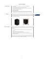
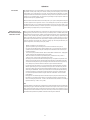
Cinema S5 Dipole3x
Owners Manual
IMPORTANT SAFETY INSTRUCTIONS
CAUTION!
RISK OF ELECTRIC SHOCK
DO NOT OPEN
USE IN DRY LOCATIONS ONLY
The lighting flash with arrowhead
symbol, within an equilateral triangle, is
intended to alert the user to the presence
of uninsulated "dangerous voltage"
within the product's enclosure that may
be of sufficient magnitude to constitute a
risk of electric shock to persons.
1.
1.
2.
3.
4.
5.
6.
7.
8.
9.
10.
11.
12.
13.
14.
15.
16.
17.
18.
19.
20.
CAUTION:
TO PREVENT THE RISK OF ELECTRIC
SHOCK, DO NOT REMOVE COVER
(OR BACK). NO USER SERVICEABLE
PARTS INSIDE. REFER SERVICING TO
QUALIFIED SERVICE PERSONNEL.
The exclamation point symbol, within
an equilateral triangle, is intended
to alert the user to the presence of
important operating and maintenance
(servicing) instructions in the literature
accompanying the product.
READ INSTRUCTIONS - All safety and operating instructions should be read before this product is operated.
RETAIN INSTRUCTIONS - The safety and operating instructions should be retained for future reference.
HEED WARNINGS - All warnings on this product and in the operating instructions should be adhered to.
FOLLOW INSTRUCTIONS - All operating and use instructions should be followed.
WATER & MOISTURE - Do not use this produt near water - for example, near a bathtub, washbowl, kitchen sink,
laundry, tub, in a wet basement, near a swimming pool, or the like.
ATTACHMENTS - Do not use any attachments not reccommended by the product manufacturer as they may
cause hazards.
ACCESSORIES - Do not place this product on an unstable cart, stand, tripod, bracket, or table. The product may
fall, causing serious injury to a child or adult, and serious damage to the product. Use only with accessories
reccommended by the manufacturer.
WALL or CEILING MOUNTING - This product should be mounted to a wall or ceiling only as recommended by the
manufacturer.
VENTILATION - This product should be situated so that its location or position does not interfere with its proper
ventilation. For example, this product should not be situated on a bed, sofa, rug, or similar surface that may block
the ventilation openings; or placed in a built-in installation such as a bookcase or cabinet that may impede the
flow of air through the ventilation openings.
HEAT - This product should be situated away from heat sources such as radiators, heat registers, stoves, or
other equipment that produce heat.
POWER SOURCE - This product should be operated only from the type of power source indicated on the marking label.
If you are unsure of the type of power supply to your home, consult your product dealer or local power company.
POWER CORD PROTECTION - Power-supply cords should be routed so that they are not likely to be walked on
or pinched by items placed upon or against them, paying particular attention to cords at plugs, convenience
receptacles, and the point at which they exit from the subwoofer.
CAUTION: To prevent electric shock, match wide blade of power plug to wide slot of receoptacle and fully insert.
OVERLOADING - Do not overload wall outlets, extension cords, or integral convenience receptacles as this can
result in a risk of fire or electric shock.
CLEANING - This product should be cleaned only as recommended by the manufacturer.
NONUSE PERIODS - The power cord of the subwoofer should be unplugged from the outlet when left unused for
a long period of time.
OBJECT & LIQUID ENTRY - Care should be taken so that objects do not fall and liquids are not spilled onto the enclosure.
DAMAGE REQUIRING SERVICE - The subwoofer should be serviced by qualified service personnel when:
a. The power-supply cord or plug has been damaged.
b. Objects have fallen or liquid has been spilled into the subwoofer.
c. The subwoofer has been exposed to rain.
d. The subwoofer does not appear to operate normally or exhibits a marked change in performance.
e. The subwoofer has been dropped or damaged.
SERVICING - Do not attempt to service the product yourself, beyond what is described in these operating instructions.
REPLACEMENT PARTS - When replacement parts are required, be sure the service technician has used replacement
parts specified by the manufacturer or have the same characteristics as the original part. Unauthorized substitutions
may result in fire, electric shock, or other hazards.
SAFETY CHECK - Upon completion of any service or service of repairs to this product, ask the service technician to
perform safety checks to determine that the product is in proper operating condition. All other servicing should
be referred to qualified service personnel.
2
CONTENTS
Introduction...................................................................... 4
About XTZ......................................................................... 4
Product information......................................................... 5
Installation....................................................................... 6
Calibration........................................................................ 9
Care of your speaker...................................................... 11
Troubleshooting and service......................................... 11
Technical specifications................................................. 12
Service & support.......................................................... 13
3
Introduction
Introduction
Congratulations on your purchase of XTZ loudspeakers. This product represents the state of the art in
loudspeaker performance and will provide you with years of listening pleasure when properly setup
and cared for. We strongly urge you to read this owner’s manual and follow the instructions provided
to help you attain maximum system performance.
If you have no previous experience of these kinds of installations, or if you have any questions, feel
free to contact our free of charge support and we will help you. (See further under the heading of
Support on the last page of this manual).
Prior to installation
Please unpack the system carefully. Use caution when lifting or moving to avoid injury. Save the carton
and all packaging materials for future use. Packing this unit in any other carton may result in damage
when shipping that is not covered by the warranty. Fill out and return the warranty card to complete
your product registration and record the serial number and purchase information in the space provided for your own records.
Operating environment
Operating environment temperature 40°F to 95°F (4°C to 35°C) with less than 85% relative humidity.
Do not install this product in a poorly ventilated area, or in locations exposed to high humidity, direct
sunlight, or strong artificial light.
Warning!
This equipment is not waterproof. To prevent a fire or shock hazard, do not expose this equipment
to rain, moisture or any liquids. Do not place a container filled with liquid on or near this equipment
(such as a drink or flower vase). To prevent a fire hazard, do not place an open flame (such as a lighted
candle) on this product. Please observe all warnings on the equipment itself. There are no user serviceable parts inside. Please refer all service questions to your authorized dealer.
About XTZ
Philosophy
Our reference and starting point is to recreate a natural sound, but also in respect to the fact that
acoustics and sound always is a matter of taste.
XTZ Goals
To provide the optimal relation between price, performance and quality on the market.
Our concept:
- To produce the perfect compromise.
- Cost-effective manufacturing at a large scale.
- The quality of our products is more important than the marketing.
- Reduce the number of middlemen.
Contact us
Website: www.xtz.se / www.xtzsound.com
E-mail: [email protected]
4
Product information
Product features
----------
3-way speaker with dipole or dipole 3X option for the ultimate suddound experience
One 4” woofer
Two 3” full range drivers mounted as dipole, one left and one right
Two 1” softdome tweeters in a Dual-tweeter configuration for highest SPL and low distortion
Optimized cabinet size with non parallel walls
Separate left & right speaker
Twisted pair internal cabling
Can be placed on stands (e.g. Cinema Stand), or wall mounted (e.g. with special flush mount).
The cloth grill and logos are fixed with magnets which gives several “looks” for your own taste.
Grill & logo
The cloth grill can be chosen to have fixed to the speaker if you want to hide the drivers or taken of if you
want a rougher but still a clean look. This due to there are magnets hidden in front baffle of the speaker
and on the cloth grill. The logos work the same way and and can be placed either on top of the speaker
or at the front beside the front baffle..
Before you begin
Your new loudspeaker provides for a number of installation options. Read all the installation information
contained within this manual in order to determine which installation option is best for your system
configuration.
-- Select appropriate cable with connector type (banana plug, fork/spade or bare) to match your
equipment
-- Determine optimum loudspeaker mounting location
-- Obtain any appropriate mounting hardware (i.e. matching stand or wall mounts)
-- Determine system configuration (e.g. music or surround sound system type for proper equipment settings & calibration)
NOTE: Remember to make all equipment connections with system power disconnected to reduce
the risk of personal shock or damage to equipment. Consult your dealer or [email protected] for optional
accessories that may be required to properly complete your system installation.
5
Installation
Cables
When installing your new loudspeakers you should use speaker cables of cross sectional area of
minimum 2.5 mm2 or 14 AWG. It is possible to use banana plug or fork/spade as connectors, or simply
bare wire. Keep in mind that if you use the loudspeakers as surrounds or back channel larger guage
cable may be necessary beacuse the signal path is longer. Keep the length of cables as short as possible.
Placement
These loudspeakers cover a broad range of frequencies and have unique dispersion characteristics
that will ease setup in achieving an excellent sounding system. The S5 has three sound options; front
firing (e.g. normal speaker), dipole with the two side drivers creating a more diffuse sound stage
and dipople 3X which is combination of front firing and dipole.With that said, please keep in mind that
loudspeaker placement will influence the frequency response, sound stage and imaging as the room
has a significant impact on the sound. Placing the loudspeakers in the wrong location may degrade
sound quality, frequency response and substantially reducing your overall listening pleasure. Many
rooms often end up with non-optimal placement, depending on the size and location of the furnishings
within your room. Finding the optimal location usually requres some experimentation to determine
what sounds best in your room, from your listening position(s). We suggest you read the general
guidelines below and place the loudspeakers in one of the suggested locations. We also recommend
keeping the speaker’s distance to the listening position as similar as possible for all channels, then as
a fine tune, use your AV Receiver/pre to adjust delays of each channel individually.
Proceed to listen to the loudspeakers multiple times, trying a few different locations before settling on
the final location. To do this, perform basic setup and listen to a familiar music track or movie scene.
Then move the loudspeakers to an alternate location & repeat listening to the same music track or
movie scene. If you have a test CD and SPL meter or preferably one of our measurement systems
(Room Analyzer II / II Pro), performing a basic frequency response test can help you determine
which location provides the best frequency response.
General guidelines
The S5’s are intended to use as surrounds or back channel speakers. It can of course also be used in the
front as Left, Right and Center speaker. They are made in left and right version that is just mirrored. The
speakers should be placed with the center of the tweeter array at ear height and the speakers directed
towards the listening position, as the figures below shows. Some experimentation with speaker “toe-in”
will yield improvements in sound stage, imaging and tonal quality. The speakers can be placed either
on stands (Cinema Stand) or mounted on the wall with the integrated wall mount (Flush Mount).
The speakers can be used in the setup of your choice (2, 3,5 or 7 channels). Our recommendation
for home cinema is to use them with a dedicated subwoofer(s) (SUB1x12, SUB2x12, or SUB3x12) to
properly handle the lowest frequencies and improve the overall dynamic range. If your choice is a five
channel (5.1) setup you can experiment with the placement for your surrounds channel speakers as
shown in the figure to the left. If your choice is a seven channel (7.1) setup you can experiment with
the placement for your surround and back channel speakers as shown in the figure to the right. If the
listening position is against the back wall our recommendation is to go for five channel setup with the
speakers placed beside the listening position as the figure to the left shows or mounted on the back
wall with the speakers tilted in towards the listening position.
6
Caution!
-- Do not place the loudspeaker next to heat sources, such as furnace registers, radiators, etc.
-- Do not place the loudspeaker near sources of excessive moisture, such as evaporative coolers,
humidifiers, etc.
Installation
The connections for the loudspeakers are located on the rear of the unit. The figure down to the right
illustrates the input terminals of the loudspeaker with only normal single wire cable as an option.
Connecting the speaker
We recommend to use normal single wire cable due the speaker is equipped with a single connection.
For the use as a front firing speaker connect the same wire of the cable from + on the amplifier to the
+ on the speaker marked 3 and - on the amplifier to - on the speaker marked as 2. No jumpers should
be attached.
For the dipole mode connect to the cable to the lower pair of connector markes 1 and 2, no jumpers
should be attached.
If you want use the dipole 3X sound mode use the lower pair of connectors and install jumpers
between 3 & 4
Wall mounting
The S5 has one key-hole type wall mount integrated in the back baffle, see the figure below to the left.
It also has three sets of threaded inserts to attach the mounting bracket of your your choice, all with
a distance of 76 mm (3”) which are inted to be used with our Flush Mount Brackets, see figure here to
the right. This spacing is also widely compatible with many aftermarket mounting brackets. To the right
below is an figure illustrating how an S5 speaker looks mounted on a wall.
Note:
There are 2 sets(4pcs x2mm thick, 4pcs x6mm thick) of rubber spacers included with the M6. These can
be placed on the back of the speaker to prevent scratching the wall and allow for space to run speaker
wires. Choose the spacer thickness according to how far you need the speaker away from the wall.
7
On stands
You can use our matching stand (Cinema Stand) with integral cable chamber to route and hide the cable
inside the stand. The stand includes a bracket to mount the speaker securely, see the figure below to the
right. This macthing stand has the indentical matte black finish as the speaker and places the tweeter
arrary at the recommended listening height. The S5 can be placed standing up as surround back left
and right speaker back channel left and right speaker.
8
Calibration
Introduction
For optimal performance, you should calibrate your system to ensure proper level matching between
all speakers and the proper setting of all controls (including crossover frequency, phase, and any
channel delays your receiver/processor may offer). This procedure will vary depending on system
configuration and the information below is provided as a basic guide to assist you. Refer to the owner’s
manual for your receiver/processor for information on performing the steps required to enter their
setup mode and adjust any applicable settings.
After all connections have been made, turn on the AC power to your system, starting with the first piece
of source equipment in the signal chain (such as a CD or DVD player), then power on any dedicated
equalizer, then power on your receiver/processor/amplifier(s), and last but not least, power on the
subwoofer. You will need to enter your receiver’s/processor’s setup mode and adjust any applicable
speaker settings to properly match your system configuration
Receiver/Processor
With Automated Setup &
Calibration Function
After you have verified all speakers are connected and you have measured distances of each to the
listening position, perform the auto-setup routine on your receiver/processor (if available). Many newer
home theater receivers/processors combine a measurement microphone and an automated setup
routine to assist you with proper setting of speaker levels, crossover frequency, speaker delay and
phase. Consult the owner’s manual for your receiver/processor for further instructions on how to
perform the setup routine. After the auto-setup routine is complete, verify the final settings the receiver/
processor selected to ensure there are no erroneous settings (e.g. the settings should match your
system configuration). Some settings to verify may include:
-- Number of speakers (e.g. 7.1 or 5.1 system, etc.)
-- Type/size of speakers (e.g. small or large front/surround and subwoofer set to yes/on)
-- Crossover point should be similar for identical speakers (e.g. if your system using 3 of the samespeakers for all front channels, verify the receiver/processor selected the same crossover point
for all these channels)
-- Crossover frequency should be selected. We recommend 80Hz for the M6 to start. Slighly higher
or lower xover point may yield better results in your system.
-- Note: some receivers do not have an adjustable frequency, instead there is only a choice of
“small” or “large”. In this case, we recommed choosing “small”.
-- Gain settings for each channel should be reasonably close (e.g. if the speakers are placed at even
distances, the gain setting for each channel should typically be within a couple dB from channel to
channel). If the receiver/processor gain trim setting for the subwoofer channel is a large value (e.g.
+12 or -12dB) you may need to increase the subwoofer’s gain to achieve a better match
-- Low subwoofer gain/trim settings (on your receiver/processor) effect the operation of the “AUTO
ON/OFF” signal sensing circuit. If your receiver/processor gain is set to a low values (e.g. attenuating the signal -6dB or more) this reduces the signal available to properly “turn on” the subwoofer
when using the “AUTO ON/OFF” feature. If your subwoofer turns off unexpectedly when watching
movies at low volumes, you may wish to increase the receiver’s/processor’s subwoofer gain
trim, and manually reduce the volume using the subwoofer’s “BASS LEVEL” control to maintain
proper balance.
-- Polarity/phase; This should be adjusted for smoothest frequency response near the xover point.
-- EQ settings; if your receiver/processor allows you to see the eq settings for each channel, verify
that it is not adding any extra “limiter”, or “HPF” to the subwoofer channel, and that it is not adding a
high level of boost (e.g. >+3dB) or cut (e.g. -10db).
NOTE:
In some installations, automated room eq algorithms may make undesired changes to the subwoofer
signal settings trying to obtain what they believe is the best room response curve. In some systems
these changes have been known to degrade the overall sound quality of the subwoofer. If using a
receiver/processor with automated room eq function, we advise you listen to the system first with the
eq disabled, then again with the eq enabled, to determine if the changes are beneficial.
9
Receiver/Pre-amp Without
Automated Setup
Older receivers and/or music preamps may not provide an automated setup function. With these sytems,
optimal calibration usually requires some type of test equipment be utilized to provide test tones and
take measurements to properly calibrate your system. Some equipment you may use for this includes:
-- One of our measurement systems Room Analyzer II / II Pro. They are excellent tools to use
when optimizing and setting up a subwoofer or multiple subwoofers in a system.
-- Test signal source; pink noise and/or sine wave of various frequencies (CD, DVD, your receiver/preamp, or external measurment equipment)
-- SPL meter (low cost handheld versions can be purchased online)
-- RTA or other frequency response measurment tool (optional)
-- Start with a quiet room free of excess background noise (e.g. people talking, kids playing, dogs
barking, etc.).
-- Verify that subwoofer control settings match illustrations for your type of system configuration
-- Set any receiver/pre-amp speaker settings at an appropriate starting point (e.g. crossover). We
recommend 80Hz xover as a good starting point.
-- Start playing a test signal with energy in the subwoofer crossover region (e.g. full bandwidth pink
noise) through all speakers
-- While observing an SPL meter (or listening to the mid-bass level), have an assistant adjust the
“VARIABLE PHASE” knob from 0° to 180° and observe any change in mid-bass level near the xover
frequency. Set the control to the position with the greatest amount of bass.
-- Play a test signal (e.g. pink noise) through only 1 speaker at a time. If using your receiver, you may
need to enter it’s setup mode to perform this function.
-- Place an SPL meter in your typical listening position, approximately at ear height (use of a tripod
may be required), and set to “C” weighting and “Slow” response (if those settings are available)
-- Adjust volume to a modest level -typically 75-85dB (loud enough to clearly hear, but not excessively
loud)
-- Adjust controls as necessary to play the same test tone through each speaker and subwoofers(s)
in the system, 1 speaker at a time.
-- Adjust the individual channel gain/trim of your equipment to obtain the same SPL reading from
each speaker as you measured from the first speaker
A home theater receiver may walk you through portions of this procedure. Follow any instructions
from your receiver’s owner’s manual as applicable to your system setup. Once finished, listen to some
familiar music and movie tracks. Minor adjustment of the levels may be desired. Do not be afraid to
experiment with adjustments and try different EQ settings to find what may improve the sound in
your system and room the best!
NOTE:
There are limitations on how well the bass management works in a receiver/processor. The settings
for the subwoofer(s) might need to be adjusted manually either on the subwoofer(s) OR preferably in
the receiver/processor. For some cases when having only one “SUBWOOFER” output jack and multiple
subwoofers and the subwoofers are not placed symmetrically in the room (e.g. having an opening on
one side of the room) you might need to apply different settings for the “VARIABLE PHASE”, “BASS LEVEL”
and EQ setting on the subwoofers. There is also the option to use one of our measurement systems
Room Analyzer II / II Pro. They are excellent tools when optimizing and setting up a subwoofer or
multiple subwoofers in a system. Do not be afraid to experiment with slight adjustments to find what
may improve the sound in your system and room the best!
Do not hesitate to contact us at [email protected] for questions about settings. We are happy to assist you
in optimizing your system!
10
Care of your speaker
Your new speakers does not require any regular maintenance or calibration. Normal dusting or cleaning
of the surface for appearance purposes is all that is required.
Cabinet and baffle
Avoid using harsh detergents or chemicals when cleaning the cabinet. Abrasives, detergents, or
cleaning solutions may damage the finish on the cabinet. We recommend using only a damp cloth or
automotive grade “quick detailer” designed for painted surfaces, plastic & metal trim, to clean the cabinet.
Grill
The cloth grill may be carefully cleaned using a vacuum. Animal hair can be removed using masking
tape or similar. Avoid using brushes with stiff bristles that may damage the grill cloth.
Woofer/Tweeter
DO NOT use liquids, brushes or a vacuum to clean the drive units. Avoid touching the tweeter dome as
this could result in permanent damage.
Troubleshooting and service
If you should experience a problem with the operation of your speaker, here is a quick trouble shooting
guide to help:
PROBLEM: Speaker has no -- Check to insure the speaker wire is connected securely at both the amp and speaker connections
-- Make sure the binding posts are snug
output
-- If only using 1 set of wires (no bi-wire), make sure the gold plated jumpers are properly connecting
HF to LF for both + and - connections. The binding posts should be snug to the jumper.
-- Verify the source is working (try connecting to a speaker you know is working)
-- In some cases the source material may not play all 5.1 or 7.1 speakers all of the time (ie, 2 channel
stereo will not have any output at the center channel)
PROBLEM: Speaker has -- Check to insure the speakers wire is connected with correct polarity (+ to +, - to -)
minimal bass or image is poor -- If only using 1 set of wires (no bi-wire), make sure the gold plated jumpers are properly connecting
HF to LF for both + and - connections. The binding posts should be snug to the jumper.
PROBLEM: Intermittent sound -- Check for loose, frayed or shorted speaker wire. It is possible for frayed wire to touch the other
terminal creating a short or intermittent short
-- Make sure the binding posts and jumpers are snug
PROBLEM: Sound coming from -- Both HF and LF inputs must be connected. Typically, you will use the included jumpers for this.
If you are Bi-wiring, check that all wires are connected securely at both the amp and speaker
woofer or tweeter only
connections
-- If only using 1 set of wires (no bi-wire), make sure the gold plated jumpers are properly connecting
HF to LF for both + and - connections. The binding posts should be snug to the jumper.
-- Make sure the binding posts are snug
The following conditions -- The unit has been exposed to excessive liquid.
require service by a qualified -- The speaker sounds is abnormal and there is a “burned” smell .
-- You dropped the speaker and you hear something is loose inside.In this case if you use it its risk of
technician:
burn the amplifier.
-- Part of the cabinet, drivers, or electronics have been physically damaged.
11
Technical specifications
Construction type
Enclosure
3-way, Dipole, Dipole 3X
Sealed
Anechoic frequency range
80 Hz - 30 kHz, +/- 3 dB
In-room frequency range
70 Hz - 30 kHz, +/- 3 dB
Crossover frequencies
400 Hz, 1.2 kHz
Sensitivity
87 dB, 2.83 V/1 m
Impedance
4 ohm nominal
Recommended hi-pass
Recommeded amp-power
Binding posts
Color
Warranty
80 - 120 Hz, 24 dB/oct.
50 - 150 W RMS
Gold-plated / Banana plug / Spade / Bare wire
Matte black, piano black baffle
Five years
Dimensions (HxWxD)
11.1 x 8.0 x 8.9”
282 x 203 x 225 mm
Weight
16.5 lbs. (7.5 kg) / pcs
Specifations subject to change without notice.
12
Service & support
”Do It Yourself” - service
We apply “do-it-yourself” service on all XTZ products. If you by yourself are able to find out what part
of the loudspeaker is defective, you are fully allowed to unmount that part (which would normally be a
driver, a filter or the amplifier) and send it back to us for exchange.
IMPORTANT!
Always contact your dealer or us before taking the loudspeaker apart. It can also help you finding
the fault.
You can of course always choose to return the whole loudspeaker; therefore you should save the original package.
If something is broken
Where to send the product
for a warranty repair
If you cause additional defects by yourself when unmount the defective part, the warranty still applies
if it is obvious that the part had a manufacturing defect. In other cases however, the warranty does not
apply if you cause other defects on the loudspeaker
For service we refer to your retailer.
For questions regarding service, contact us by email: [email protected]
Website: www.xtz.se / www.xtzsound.com
Support
To aid service, XTZ products are constructed and produced using common technology, so that basically
most people are able to “unscrew”
the loudspeaker using common
tools..
Please contact our free of charge support if you need installation advice, or if any problem occurs
during the installation.
Contact us by e-mail [email protected] and include your phone number if you wish verbal help, and
we will call you back.
Thanks for your purchase!
13
ALWAYS pack the product / part very
carefully. Unfortunately damages
during transportation are very
common. If the package is weak,
the transporting company does
not compensate damages. Always
enclose a copy of the receipt and a
description of the defect.
14