1
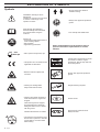
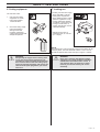
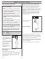
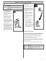
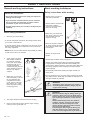
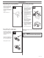
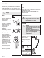
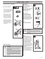
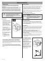
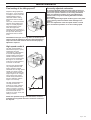
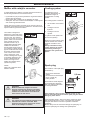
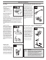
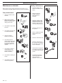
322E 325E-X
Operator's Manual
Read through the Operator‘s manual carefully and
understand the content before using the machine.
101 89 75-26
EXPLANATION OF SYMBOLS
Symbols
• Arrows which show limits for
handle mounting.
WARNING! The edger can be
dangerous!
Careless or incorrect use can result
in serious or fatal injury to the
operator or others.
Read through the Operator's
Manual carefully and understand
the content before using the
machine.
Always use:
• A protective helmet where there is
a risk of falling objects.
• Ear protection
• Approved eye protection
max
10000 rpm
• Always wear approved protective
gloves.
• Use anti-slip and stable boots.
Other symbols/decals on the machine refer to
special certification requirements for certain
markets.
• Max. speed of output axle, rpm
• This product is in accordance with
applicable CE directives.
Checks and/or maintenance should
be carried out with the engine
switched off, with the stop switch in
the STOP position.
• Beware of thrown objects and
ricochets.
Always wear approved protective
gloves.
• Warning for rotating blade.
Keep hands and feet clear.
Regular cleaning required.
• Warning! The blade continues to
rotate even after the engine has
stopped.
Ocular control.
When the engine has stopped,
stop the blade from rotating by
letting the blade come in contact
with the ground.
Indicates the direction of rotation.
15 m
50FT
2 – English
15 m
50FT
• The operator of the machine must
ensure that no persons or animals
comes within a 15 metre radius
while working.
Approved eye protection must
always be used.
CONTENTS
List of Contents
Husqvarna AB has a policy of continuous product development
and therefore reserves the right to modify the design and
appearance of products without prior notice.
EXPLANATION OF SYMBOLS
Symbols ............................................................................... 2
CONTENTS
List of Contents ................................................................... 3
!
WARNING!
Under no circumstances may the design of
the machine be modified without the
permission of the manufacturer. Always
use genuine accessories. Non authorised
modifications and/or accessories can result
in serious personal injury or the death of
the operator or others.
SAFETY INSTRUCTIONS
Personal protective equipment ............................................ 4
The machine's safety equipment ......................................... 4
Control, maintenance and service of the
machine's safety equipment ................................................ 6
General safety instructions .................................................. 8
General working instructions ............................................. 10
Basic working techniques .................................................. 10
WHAT IS WHAT?
What is what on the edger? ............................................... 12
ASSEMBLY
Assembling the loop handlebar ......................................... 13
Assembling the angle gear ................................................ 13
Assembling the blade ........................................................ 13
FUEL HANDLING
Fuel mixture ....................................................................... 14
Fuelling .............................................................................. 14
START AND STOP
Checks before starting ...................................................... 15
Start and stop .................................................................... 15
MAINTENANCE
Carburettor ........................................................................ 16
Muffler and catalytic converter .......................................... 18
Cooling system .................................................................. 18
Spark plug ......................................................................... 18
Air filter .............................................................................. 19
Angle gear ......................................................................... 19
Lubricating the flexible drive shaft ..................................... 19
Adjusting the edger's cutting depth ................................... 19
Maintenance schedule ...................................................... 20
TECHNICAL DATA
322E .................................................................................. 22
325E-X .............................................................................. 22
English –
3
SAFETY INSTRUCTIONS
Personal protective equipment
IMPORTANT INFORMATION
• An edger used incorrectly or carelessly can become a
dangerous tool, that can cause serious or fatal injury to
the operator or others. It is extremely important that
you read and understand the content of this manual.
• When using an edger, personal protective equipment
approved by the appropriate authorities must be used.
Personal protective equipment does not eliminate the
risk of accidents, however, it can reduce the effects of
an injury in the event of an accident. Ask your dealer
for help when choosing protective equipment.
!
WARNING!
Remove your hearing protection as soon as
you stop the engine, so that you can hear any
noises or warning signals.
GLOVES
Gloves should be worn when
necessary, e.g., when assembling cutting equipment.
EAR PROTECTION
Ear protection offering sufficient dampening effect should
be used.
EYE PROTECTION
Blows from branches or
objects thrown by the rotating
cutting equipment can damage
the eyes.
The machine’s safety equipment
This section describes the machine’s safety equipment, its
function and how checks and maintenance are carried out to
ensure that it operates correctly. (See the chapter “What is
what” to locate where this equipment is positioned on your
machine.)
!
WARNING!
Never use a machine with defective safety
equipment. Follow the control, maintenance
and service instructions described in this
section.
1. Throttle trigger
lock
The throttle trigger lock is
designed to prevent the throttle
from accidentally being
engaged. When the trigger
lock (A) is pressed into the
handle (= when you hold the
handle) the throttle (B) is
released.
When the grip on the handle is
released the throttle and the
throttle trigger lock return to
their original positions. This
takes place via two independent return spring systems. This
means that the throttle is
automatically locked in the
“idling” position.
A
B
2. Stop switch
The stop switch should be
used to stop the engine.
"
BOOTS
Use anti-slip and stable boots.
CLOTHING
Wear clothes made of a strong
fabric and avoid loose clothing
that can catch on shrubs and
branches. Always wear heavyduty long pants. Do not wear
jewellery, shorts, sandals or go
barefoot. Secure hair so it is
above shoulder level.
FIRST AID KIT
A first aid kit should be carried
by operators of the edger.
4 – English
3. Cutting attachment
guard
This guard is intended to
prevent objects from being
thrown towards the operator
and to protect the operator
from unintentionel contact with
the cutting attachment.
SAFETY INSTRUCTIONS
4. Vibration damping
system
Your machine is equipped with
a vibration damping system,
which is designed to give as
vibration-free and comfortable
use as possible.
The use of incorrect cutting
equipment increases the level
of vibration.
The machine’s vibration
damping system reduces the
transfer of vibrations between
the engine unit/cutting equipment and the machine’s
handle unit.
!
WARNING!
Over exposure to vibrations can result in
blood-vessel or nerve injury to persons
suffering with blood circulation problems.
Seek medical attention if you experience
physical symptoms that can be related to
over exposure to vibrations. Examples of
such symptoms are “numbness”, lack of
feeling, “tickling”, “pricking”, “pain”, lack of
or a reduction in normal strength, changes in
the colour of the skin or its surfaces. These
symptoms normally appear in the fingers,
hands or wrists.
5. Muffler
The muffler is designed to give
the lowest possible noise level
and to direct the engine’s
exhaust fumes away from the
operator. Mufflers equipped
with a catalytic converter are
also designed to reduce the
hazardous substances in the
exhaust fumes.
In countries that have a warm
and dry climate the risk of fire
is obvious. We have therefore
fitted certain mufflers with a
spark arrest screen. Make sure
that your muffler is fitted with
this kind of screen.
It is extremely important that
the instructions for checking,
maintaining and servicing the
muffler are followed. (See the
section “Control, maintenance
and service of the machine's
safety equipment”).
!
WARNING!
The exhaust fumes from the engine are hot
and may contain sparks which can start a fire.
Never start the machine indoors or near
combustible material!
!
WARNING!
Mufflers fitted with catalytic converters
become extremely hot during use and after
stopping. This also applies at idling speeds.
Contact can result in burns to the skin. Be
observant to the risk of fire!
6. Cutting equipment
The blade is designed and
processed to withstand loads
that edging of a lawn involves.
7. Locking nut
The locking nut secures
the cutting equipment on
the output shaft.
English –
5
SAFETY INSTRUCTIONS
Control, maintenance and service of
the machine’s safety equipment
3. Cutting attachment
guard
• Ensure that the guard is
undamaged and is not
cracked.
IMPORTANT INFORMATION
• All service and repairs to the machine require special
training.
• This applies especially to the machine’s safety
equipment. If the machine does not meet any of the
controls listed below you should contact your
service workshop.
• The purchase of one of our products guarantees that
professional repair and servicing will be carried out
on it. If the point of purchase is not one of our
servicing dealers, please ask for details of the
closest service workshop.
1. Throttle trigger lock
• Replace the guard if it has
been exposed to impact or is
cracked.
• Always use the prescribed
blade and guard combination,
see chapter "Technical data".
4. Vibration damping
system
• Check that the throttle is
locked in the “idling position”
when the throttle trigger lock
is in its original position.
• Check the vibration damping
element regularly for material
cracks and distortion.
• Check that the vibration
damping element is
undamaged and securely
attached.
• Press in the throttle trigger
lock and make sure it returns
to its original position when
released.
• Ensure that the throttle and
throttle trigger lock move
easily and that their return
spring systems function.
5. Muffler
• See section "Start". Start the
machine and apply full
throttle. Release the throttle
and check that the cutting
equipment stops and remains
at a standstill. If the cutting
equipment rotates with the
throttle in the idling position
then the carburettor’s idling
setting must be checked. See
chapter “Maintenance”.
#
2. Stop switch
• Start the engine and make
sure that the engine stops
when the stop switch is
moved to the stop position.
6 – English
1.
Never use a machine that
has a defective muffler.
2.
Check regularly that the
muffler is secure.
3.
If your muffler is fitted with
a spark arrest screen then
it should be cleaned
regularly. A blocked
screen leads to the engine
overheating with serious
damage as a result. Never
use a muffler with a
detective spark arrest
screen.
SAFETY INSTRUCTIONS
6. Cutting equipment
7. Locking nut
The two basic rules:
• Protect your hand from injury
when assembling, use the
blade guard as protection
when tightening with a socket
spanner. Tighten the nut by
turning against the direction
of rotation. Loosen the nut by
turning in the direction of
rotation. (NOTE! the nut has
a left-hand thread).
1.
Only use the cutting
equipment we recommend! See chapter
“Technical data”.
2.
Check the cutting equipment with regard to
damage and crack
formation. Damaged
cutting equipment should
always be replaced.
• Tighten the nut using a
socket spanner, 35 - 50 Nm
(3.5 - 5 kpm).
NOTE!
The locking nut’s nylon lock must not be so worn that it can be
turned by hand. The lock shall hold at least 1.5 Nm. The nut
should be replaced after it has been put on approx. 10 times.
!
WARNING!
Always stop the engine before starting work
on any part of the cutting equipment. This
continues to rotate even after the throttle has
been released. Ensure that the cutting equipment has stopped completely and remove the
cable from the spark plug before you start to
work on it.
!
WARNING!
Never use a machine with defective safety
equipment. The safety equipment should be
maintained as described in this section. If
your machine does not meet any of these
controls you should contact your service
workshop.
English –
7
SAFETY INSTRUCTIONS
General safety instructions
IMPORTANT INFORMATION
• The machine is only designed for cutting the edges of
lawns.
• The only accessories to be used with the engine unit
as a drive source are the cutting units we recommend
in the chapter “Technical data”.
• The operator is responsible for accidents and the risk
people and property are exposed to.
Safety instructions before starting work
• Inspect the working area. Remove any objects, such as
stones, broken glass, nails, steel wire, string, etc. that can be
thrown or can wrap around the blade or blade guard.
• Keep others at a safe distance. Children, animals, onlookers
and helpers should stand outside of the safety zone of 15 m
(50 feet). Stop the machine immediately if any one should
approach.
• Check the entire machine before starting work. Replace
damaged parts. Check for fuel leakage and that all safety
guards and covers are complete and fastened securely.
Check all nuts and bolts
• Never use the machine if you are tired, if you have
consumed alcohol, or if you are taking medicines that
can affect your sight, your judgement or the control of
your body.
• Do not operate when it's dark.
• Use personal protective equipment. See the section
“Personal protective equipment”.
• Check the blade for cracks or
any other damage.
• Never use a machine that has been modified so that it
no longer corresponds with the original design.
• Never use a machine that is faulty. Follow the maintenance, control and service instructions in this Operator’s Manual. Some maintenance and service actions
should be carried out by trained and qualified specialists. See the chapter “Maintenance”.
• Ensure the blade guard is
mounted and not damaged.
• All covers and guards must be fitted before starting
the machine. Check that the spark plug cap and HT
lead are not damaged, otherwise you could get an
electric shock.
!
WARNING!
Faulty cutting equipment increases the risk
of accidents.
• Check that the blade and blade guard are correctly secured.
Personal protection
• When adjusting the carburettor make sure the blade is held
against the ground and that no one is in the immediate vicinity.
• Always wear boots and other
equipment described in the
section “Personal protective
equipment”.
• Make sure the blade does not rotate when idling.
• Always wear working clothes
and heavy-duty long trousers.
• Never wear loose sitting
clothes or jewellery.
• Persons with long hair
should, for personal safety,
put their hair up.
Safety instructions regarding the
surroundings
• Never allow children to use the machine.
• Ensure no one comes closer than 15 metres when working.
• Never allow anyone else to use the machine without first
ensuring that they have understood the contents of the
Operator’s Manual.
8 – English
• Make sure the handle and safety features are in order. Never
use a machine that has parts missing or has been changed in
relation to the specification.
• Only use the machine for the purpose it was intended for.
SAFETY INSTRUCTIONS
Start
!
Fuel safety
WARNING!
When the engine starts with the choke lever
in the choke or starter throttle position the
cutting tool (blade or trimmer) starts to rotate
immediately.
• The complete clutch cover
with shaft must be fitted
before the machine is
started, otherwise the clutch
can become loose and cause
personal injury.
• Never start the machine
indoors. Bear in mind the
dangers of inhaling the
engine’s exhaust fumes.
• Observe your surroundings
and make sure that there is
no risk of people or animals
coming into contact with the
cutting equipment.
• Place the machine on the
ground, make sure the blade
is free from branches and
stones. Press the machine
body against the ground
using your left hand (NOTE!
Do not use your foot). Grip
the starter handle with your
right hand and pull the starter
cord.
• Always use a fuel container
with an anti-spill valve.
• Never fill the machine while
the engine is running. Stop
the engine and allow it to cool
for a few minutes before
refuelling.
• Provide good ventilation
when filling or mixing fuel
(petrol and 2-stroke oil).
• Move the machine at least
3 m from the filling position
before starting.
• Never start the machine:
a)
If you have spilt fuel on it.
Wipe up all spillage.
b)
If you have spilt fuel on
yourself or your clothes.
Change your clothes.
c)
If there is a fuel leak. Make
regular checks for leakage
from the fuel cap and the
fuel supply pipes.
Transport and storage
• Store and transport the machine and fuel so that any leakage
or fumes do not risk coming into contact with sparks or naked
flames. For example, electric machines, electric motors,
electrical switches/power switches, heaters or the like.
• When storing or transporting fuel, approved containers
intended for this purpose must be used.
• When storing the machine for long periods the fuel tank must
be emptied. Contact your local petrol station to find out how to
dispose of excess fuel.
• The engine must be cooling off before storage or packaging.
!
WARNING!
Exercise great care when handling fuel. Bear
in mind the risk of fire, explosions and
inhaling fumes.
English –
9
SAFETY INSTRUCTIONS
General working instructions
IMPORTANT INFORMATION
• This section takes up the basic safety precautions for
working with the edger.
• If you encounter a situation where you are uncertain
how to proceed you should ask an expert. Contact
your dealer or your service workshop.
• Avoid all usage which you consider to be beyond your
capability.
Basic safety precautions
1.
Observe your surroundings:
Basic working techniques
Safety instructions while working
• Always ensure you have a
safe and firm foothold.
• Always hold the machine with
both hands. Hold the
machine of the right-hand
side your the body.
• Make sure your hands and
feet do not come into contact
with the blade when the
engine is running.
• To ensure that people, animals or other things cannot affect
your control of the machine.
• To ensure that the above mentioned do not come into contact
with the cutting equipment or objects that can be thrown by
the cutting equipment.
• When the engine is switched
off, keep your hands and feet
away from the blade until it
has stopped.
• NOTE! Never use a machine without the possibility of calling
for help in the event of an accident.
• Always cut edges at full
throttle.
2.
3.
Avoid usage in unfavourable weather conditions.
For example, thick fog,
heavy rain, strong winds
or extreme cold, etc. To
work in bad weather
conditions is tiring and can
create dangerous circumstances, e.g. slippery
surfaces.
Make sure you can walk
and stand safely. Look out
for any obstacles with
unexpected movement
(roots, stones, branches,
pits, ditches, etc.). Take
great care when working
on sloping ground.
• Always keep the blade close to the ground.
• Always drop to idling speed after each working operation.
Longer periods running at full throttle without loading the
engine (that is without resistance, which the engine feels from
the cutting equipment when trimming) can lead to serious
engine damage.
• Be especially careful when pulling the edger towards you
during work.
• If heavy vibrations occur, stop the engine. Remove the spark
plug cable from the spark plug. Check that the machine is not
damaged. Repair any damage.
!
!
4.
The engine should be switched off before moving.
5.
Never put the machine down with the engine running
unless you have good sight of it.
10 – English
WARNING!
Sometimes grass and stones can collect in
the blade guard and blade. Always stop the
engine when cleaning.
WARNING!
Beware of thrown objects. Always wear eye
protection. Never lean over the blade guard.
Stones rubbish etc. can be thrown up into the
eyes resulting in blindness or other serious
injury.
Keep unauthorised persons at a distance.
Children, animals, onlookers and helpers
should be outside the safety zone of 15
meters (50 feet). Stop the machine immediately if anyone approaches.
The bevel gear unit can get hot during use
and may remain so for a while afterwards.
There is a risk of slight burns if you touch it.
SAFETY INSTRUCTIONS
Safety instructions after completing work
• Ensure the blade has
stopped before cleaning,
carrying out repairs or an
inspection. Remove the spark
plug cable from the spark
plug.
• Wear heavy-duty gloves
when carrying out repairs on
the edger.
• Store the machine out of
reach of children.
• Only use original spare parts
with repair.
English –
11
WHAT IS WHAT?
1
4
21
4
20
1
26
24
What is what on the edger?
1.
Blade
14. Air purge
2.
Grease filler cap
15. Air filter cover
3.
Angle gear
16. Clutch cover
4.
Blade guard
17. Handlebar adjustment
5.
Shaft
18. Locking nut
6.
Loop handlebar
19. Support flange
7.
Throttle
20. Drive disc
8.
Stop switch
21. Locking handle
9.
Throttle trigger lock
22. Socket spanner
10. Cylinder cover
23. Operator's Manual
11. Starter handle
24. Locking pin
12. Fuel tank
25. Allen key
13. Choke
26. Carburettor screwdriver
12 – English
ASSEMBLY
Assembling the loop handlebar
• Position the handle on the
shaft. Note that the handle
must be mounted below the
arrow on the shaft.
Assembling the blade
Fit the blade as follows:
1.
Fit the drive disc (A) on the
outgoing shaft. Make sure
that the edge that fits in
the hole of the blade is
facing outward.
2.
Block the blade rotation by
inserting locking pin in the
hole behind the blade
guard engaging it in the
corresponding hole in the
drive disc.
3.
Fit the blade (B) on the
drive disc.
4.
Fit the support
flange (C). The support
flange must be fitted with
its outer edge hard up
against the blade.
• Fit the bolt, securing plate
and wing nut as shown in the
diagram.
• Tighten the wing nut.
Assembling the angle gear
• Assemble the angle gear
back on the supporting tube.
Turn the blade so that the
drive shaft engages in the
angle gear.
5.
Fit the locknut (D). NOTE!
The locknut has left-hand
threads. The tightening
torque of the locknut is 35
– 50 Nm.
6.
Remove the locking pin.
A
B
C
D
NOTE! Do not forget to remove the locking pin before using
the machine.
!
WARNING!
Under no circumstances may the edge cutter
blade be used without the blade guard fitted.
• Position the angle gear so
that its slot is aligned with the
line on the supporting tube.
• Firmly tighten the screw.
English –
13
FUEL HANDLING
Fuel mixture
NOTE!
The edger is fitted with two-stroke engines and must always be
run on a mixture of petrol and two-stroke oil. To ensure the
correct mixture proportions it is important to measure the
quantity of oil accurately. When mixing small amounts of fuel
small discrepancies in the amount of oil have a great bearing on
the proportions of the fuel mixture.
!
WARNING!
Always provide good ventilation when
handling fuel.
Petrol
• Always use unleaded, oil
mixed, quality petrol! (at least
90 octane). Leaded petrol will
destroy the catalytic
converter and it will no longer
serve its purpose.
• The lowest recommended
octane rating is 90. If you run
the engine on a petrol with a
lower octane rating than 90
so-called “knocking” can
occur. This leads to an
increased engine
temperature, which can result
in a serious engine
breakdown.
Mixture
• Always mix petrol and oil in a clean container intended for
petrol.
• Always start by filling half the quantity of petrol required. Then
add the entire oil quantity. Mix (shake) the fuel mixture. Fill the
remaining quantity of petrol.
• Mix (shake) the fuel mixture carefully before filling in the
machine’s fuel tank.
• Do not mix fuel for more than max. one month's supply of fuel.
• If the edger is not used for a long period of time, the fuel tank
should be emptied and cleaned.
!
Fuelling
!
• When working at continuous
high revs a higher octane
rating is recommended.
Two-stroke oil
• For the best results use
HUSQVARNA two stroke oil,
which has been specially
developed for 2-stroke
engines. Mixing ratio 1:50
(2%).
• If HUSQVARNA two stroke
oil is not available you can
use a high quality two-stroke
oil intended for air cooled
engines. Contact your dealer
when selecting an oil. Mixing
ratio: 1:33 (3%).
• Never use two-stroke oil
intended for water cooled
outboard motors, so-called
outboard motor oil.
• Never use oil intended for
four-stroke engines.
WARNING!
The catalytic converter muffler becomes very
hot during and after use. This also applies
during idling. Be aware of the fire hazard,
especially when handling the saw near
flammable substances or vapours.
WARNING!
The following precautions reduce the risk of
fire:
Do not smoke or place any sources of heat in
the vicinity of the fuel.
Never refuel when the engine is running.
Always stop the engine and let it cool for a
few minutes before refuelling.
Open the fuel cap slowly when fuelling so that
any over pressure is released slowly.
Tighten the fuel cap carefully after refuelling.
Always move the machine from the fuelling
area before starting.
• Clean around the fuel cap.
Contamination in the tank can
disrupt operations.
• Ensure that the fuel is well
mixed by shaking the
container before filling the
tank.
Gasolin
Benzin
Essence
Gasolina
Lit.
5
10
15
20
Oil • Öl
Huile • Aceite
Lit.
US
gallon
1
2 1/2
5
14 – English
3% (1:33)
0,15
0,30
0,45
0,60
2% (1:50)
0,10
0,20
0,30
0,40
US
fl. oz.
2% (1:50)
2 1/2
6 1/2
12 7/8
3% (1:33)
3 3/4
9 3/4
19 1/4
START AND STOP
Control before starting
For reasons of safety follow
these recommendations!
• Check that the support flange
is not cracked due to fatigue
or due to being tightened too
much. Discard the support
flange if it is cracked.
• Ensure that the nut has not
lost its tightening capacity.
The nut lock shall have a
locking torque of at least l.5
Nm. The nut’s tightening
torque shall be 35-50 Nm.
• Check that the blade and
blade guard are not damaged
or cracked. Replace the
blade or blade guard if it has
been exposed to impact or if
it is cracked.
Cold engine
IGNITION: Set the stop switch
to the start position.
CHOKE: Set the choke control
in the choke position.
AIR PURGE:
Press the air purge diaphragm
repeatedly until fuel begins to
fill the diaphragm. The
diaphragm need not be
completely filled.
Warm engine
Use the same starting
procedure as for the cold
engine, but do not set the
choke control in the choke
position. The start throttle
position is obtained by setting
the choke lever in the choke
position and then returning it
to its original position.
Stop
The engine is stopped by
switching off the ignition.
!
WARNING!
When the engine is started with the choke
lever in either the choke- or start throttle
position the cutting equipment starts to rotate
immediately.
Start
Start and stop
!
WARNING !
The complete clutch cover with shaft must be
fitted before the machine is started, otherwise
the clutch can become loose and cause
personal injury.
Always move the machine from the filling
position before starting. Place the machine on
a flat surface. Make sure the blade cannot
come into contact with any object. Make sure
that no unauthorised persons are in the
working area, otherwise there is a risk of
serious personal injury. The safety distance is
15 metres.
Press the machine body
against the ground using your
left hand (NOTE! Not your
foot). Grip the starter handle,
slowly pull out the cord with
your right hand until you feel
some resistance (the starter
pawls grip), now quickly and
powerfully pull the cord.
Reset the choke control as
soon as the engine fires and
repeat until the engine starts.
When the engine starts quickly
apply full throttle and the start
throttle will automatically
disengage.
NOTE! Do not pull the starter
cord out completely and do not
release the starter cord from
the fully extended position.
This can damage the machine.
English –
15
MAINTENANCE
Carburettor
Your Husqvarna product has been designed and
manufactured to specifications that reduce harmful
emissions.
After your unit has been run 8-10 tanks of fuel the engine
has broken in. To ensure that your unit is at peak
performance and producing the least amount of harmful
emissions after break in, have your authorized servicing
dealer, who has a revolution counter at his disposal, to
adjust your carburettor for optimum operating conditions.
!
WARNING!
The complete clutch cover with shaft must
be fitted before the machine is started,
otherwise the clutch can become loose and
cause personal injury.
Operation
• The carburettor governs
the engine’s speed via the
throttle. Air/fuel is mixed in
the carburettor. The air/fuel
mixture is adjustable. To
take advantage of the
engine’s optimal output the
adjustment must be correct.
• The setting of the
carburettor means that the
engine is adapted to local
conditions, for example, the
climate, altitude, petrol and
the type of 2-stroke oil.
• The carburettor is equipped
with three adjustment
possibilities:
L = Low speed needle
H= High speed needle
T = Idle speed adjuster
screw
Basic setting
• The carburettor is set to its basic setting when test run at the
factory. The basic setting is richer than the optimal setting and
should be kept during the machine’s first working hours.
Thereafter the carburettor should be finely adjusted. Fine
adjustment should be carried out by a skilled technician.
NOTE! If the blade rotates while the engine is idling the T screw
should be turned anticlockwise until the cutting attachment
stops.
Rec. idling speed: 2 700 rpm.
Rec. max speed: See ”Technical data”.
!
WARNING!
If the idling speed cannot be adjusted so that
the cutting attachment stops, contact your
service workshop. Do not use the machine
until it has been correctly adjusted or
repaired.
Fine adjustment
• When the machine has been ”run-in” the carburettor should
be finely adjusted. The fine adjustment should be carried
out by qualified person. First adjust the L-jet, then the idling
screw T and then the H-jet.
Conditions
• Before any adjustments are made the air filter should be clean
and the air filter cover fitted. Adjusting the carburettor while a
dirty air filter is in use will result in a leaner mixture when the
filter is finally cleaned. This can give rise to serious engine
damage.
• Turn the L and H needles carefully to the middle point
between fully screwed in and fully screwed out.
• Do not attempt to adjust the needles beyond the stops as
damage can occur.
• Now start the machine as set out in the start instructions and
run it warm for 10 minutes.
NOTE! If the cutting equipment rotates/moves while idling the
T screw should be turned anticlockwise until the cutting
equipment stops.
Low speed needle L
• The fuel quantity in relation to the air flow permitted by the
throttle opening is adjusted using the L and H-needles.
Turning the needles clockwise gives a leaner fuel mixture
(less fuel) and turning them anticlockwise gives a richer fuel
mixture (more fuel). A leaner mixture gives high revs while a
richer mixture give less revs.
• The T-screw regulates the position of the throttle while the
engine is idling. Turning the screw clockwise gives a higher
idling speed while turning it anticlockwise gives a lower idling
speed.
Try to find the highest idling
speed, turning the low speed
needle L clockwise
respectively counterclockwise. When the highest
speed has been found, turn
the low speed needle L 1/4
turn counter-clockwise.
NOTE! If the cutting
attachment rotates/moves in
the idling position, turn the
idling speed screw T counterclockwise until the cutting
attachment stops.
+ 1/4
L
16 – English
MAINTENANCE
Final setting of the idling speed T
Correctly adjusted carburettor
A correctly adjusted carburettor means that the machine
accelerates without hesitation and the machine 4-cycles a
little at max speed. Furthermore, the cutting attachment
must not rotate/move at idling. A too lean adjusted low
speed needle L may cause starting difficulties and bad
acceleration.
A too lean adjusted high speed needle H gives lower power
= less capacity, bad acceleration and/or damage to the
engine.
A too rich adjustment of the two speed needles L and H
gives acceleration problems or too low working speed.
Adjust the idling speed with
the screw T, if it is necessary
to readjust. First turn the idle
speed adjusting screw T
clockwise until the cutting
attachment starts to rotate/
move.
Then turn, counter-clockwise
until the cutting attachment
stops. A correctly adjusted
idle speed setting occurs
when the engine runs
smoothly in every position. It
should also be good margin to
the rpm when the cutting
attachment starts to rotate/
move.
CAUTION! Contact your servicing dealer, if the idle speed
setting cannot be adjusted so that the cutting attachment
stops. Do not use the machine until it has been properly
adjusted or repaired.
High speed needle H
The high speed needle H
influences the power, speed,
temperature and fuel
consumption of the machine.
A too lean adjusted high
speed needle H (high speed
needle H closed too much)
gives overrevs and damages
the engine. Do not let the
machine run at full speed for
more than 10 seconds.
Turn the high speed needle
very slowly clockwise until
engine speed is reduced.
Thereafter turn the high speed
needle very slowly counterclockwise and stop when the
engine begins to run roughly.
Then turn the high speed
needle slowly the minimum
amount clockwise until the
engine runs smoothly.
The high speed needle H is
correctly set when the
machine ”4-cycles” a little. If
the machine ”whistles” the
setting is too lean. If there is
too much smoky exhaust gas
at the same time as the
machine ”4-cycles” much, the
setting is too rich.
H
NOTE! For optimum setting of the carburettor, contact a
qualified servicing dealer who has a revolution counter at
his disposal.
English –
17
MAINTENANCE
Muffler with catalytic converter
Cooling system
A muffler fitted with a catalytic converter reduces the extent of
the following substances in the exhaust fumes:
To maintain as low an
operating temperature as
possible the engine is
equipped with a cooling
system.
• Hydrocarbons (HC). Some hydrocarbons in gasoline and the
exhaust are carcinogenic.
• Nitric oxides (NO). Irritating for the breathing air-ways.
• Aldehydes. The most common formaldehyde, is carcinogenic
and causes hypersensitiveness.
NOTE! The level of carbon monoxide is not reduced. This is an
odourless and extremely poisonous substance. Therefore avoid
exposure without good air circulation.
The muffler is designed to
dampen the noise level and to
direct the exhaust fumes away
from the user. The exhaust
fumes are hot and can contain
sparks, which can result in fire
if the exhaust fumes are
directed towards a dry or
inflammable material. Some
mufflers are fitted with a
special spark arrest screen. If
your machine is fitted with this
type of muffler then the screen
should be cleaned at least
once a week. This is done
using a wire brush. If the
screen is damaged in anyway
it should be replaced. If the
screen is blocked this will
result in the engine overheating and damage to the
cylinder and piston,
NOTE!
Never use a machine with a
defective muffler.
The cooling system consists of:
1.
An air intake on the starter
unit.
2.
Cooling fins on the
flywheel.
3.
Cooling fins on the
cylinder
!
!
18 – English
WARNING!
The coating on/in the catalytic element can be
hazardous to health if consumed. Wear
protective gloves when carrying out service
work on the catalytic converter.
3
2
1
4. Cylinder cover (leads cold
air onto the cylinder).
Clean the cooling system using
a brush at least once a week,
in difficult conditions more
often.
A dirty or blocked cooling
system leads to the engine
overheating resulting in
damage to the cylinder and
piston.
Spark plug
The condition of the spark plug
is affected by:
• An incorrect carburettor
setting.
• An incorrect fuel mixture (too
much or faulty oil).
• A dirty air filter.
WARNING!
Mufflers fitted with catalytic converters
become extremely hot during use and after
stopping. This also applies at idling speeds.
Contact can result in burns to the skin. Be
observant to the risk of fire!
4
0,5 mm
These factors cause deposits
on the spark plug electrode
that may result in malfunction
or starting difficulties.
If the machine is low on power, difficult to start or runs
poorly while idling always check the spark plug first before
taking any other action.
If the spark plug is dirty, clean it and at the same time check
that the electrode gap is 0.5 mm. The spark plug should be
changed after about one month of operation or earlier if
necessary.
NOTE! Always use the recommended type of spark plug. An
incorrect spark plug can damage the cylinder/piston.
MAINTENANCE
Air filter
Lubricating the flexible drive axle
The air filter should be cleaned
regularly removing dust and
dirt to avoid:
• carburettor malfunction
• starting problems
• reduced engine power
• unnecessary wear to engine
parts
• abnormal fuel consumption
Inside the edger‘s drive shaft
is a flexible drive axle. The
flexible drive axle should be
regularly lubricated after 30
hours of operation. Loosen the
two screws on the angle gear
and remove it. The flexible
drive axle is easily removed
from the shaft by taking a firm
grip on the axle end. Lubricate
the flexible drive axle over its
entire length and reinsert it in
the shaft. Turn the axle while
inserting it so that it correctly
engages in the clutch. Replace
the angle gear on the drive
axle shaft and tighten the two
screws.
Clean the filter after every 25
hours or more regularly if
operating conditions are
exceptionally dusty.
Cleaning the air filter
Dismantle the air filter cover and remove the air filter. Wash in
clean, warm soapy water. Ensure that the filter is dry before
refitting. An air filter used for a long period of time can never be
cleaned completely. Therefore it is necessary to replace the
filter from time to time with a new filter. A damaged air filter
must always be replaced.
If the machine is used in dusty conditions the air filter
should be soaked in oil, see the section on “Oiling the air
filter“.
Oiling the air filter
Always use HUSQVARNA
filter oil, order no. 503 47 7301. The filter oil contains a
solvent to make it spread
evenly through the filter. You
should therefore avoid skin
contact. Put the filter in a
plastic bag and the pour the
filter oil over it. Knead the
plastic bag to distribute the
oil. Squeeze the excess oil
out of the filter inside the
plastic bag and pour off the
excess before fitting the filter
on the machine. Never use
common engine oil. This
would drain through the filter
quite quickly and collect in the
bottom.
Adjusting the edger's cutting depth
The cutting depth should be
adjusted before starting work.
• Loosen the locking handle
(A) and rotate the guard by
moving the locking knob
forwards or backwards. If the
locking handle is moved
forwards (from the machine)
the cutting depth is
increased. If the locking
handle is moved backwards
(towards the machine) the
cutting depth is reduced.
A
• Adjust the cutting depth.
• Lock the locking handle.
Angle gear
The angle gear is filled
a sufficient quantity of grease
at the factory. However, before
using the machine you should
check that the angle gear is
filled to 3/4 with grease. Use
HUSQVARNA special grease.
Normally, the grease does not
need to be changed except
when repairs are carried out.
!
WARNING!
Always bear the machine on the right side of
the body. Always wear protective glasses,
long trousers and heavy-duty shoes when
using the machine. Observe your
surroundings, ensure people and animals do
not come in the immediate vicinity or can be
hit by thrown objects. Apply full throttle
before the blade starts to work on the soil.
English –
19
MAINTENANCE
Maintenance schedule
Weekly maintenance
Below follows some general maintenance instructions. If you
need further information please contact your service workshop.
1.
Check the starter, the
starter cord and the return
spring.
2.
Make sure that the
vibration damping
elements are not
damaged.
1
Daily maintenance
1.
Clean the outside of the
machine.
2.
Make sure the throttle
trigger lock and the throttle
function correctly from a
safety point of view.
3.
4.
5.
6.
7.
1
3
2
3.
Check that the blade is
undamaged and not
cracked. Replace the
blade if necessary.
8.
Check that the locking nut
is tight.
9.
Check that all nuts and
screws are tightened.
20 – English
4
4.
Clean the cooling fins on
the flywheel.
5.
Clean or replace the spark
arrest screen on the
muffler.
5
4
Clean the air filter.
Replace if necessary.
Check the guard for
damage and ensure that it
is not cracked. Replace
the guard if it has been
exposed to impact or is
cracked.
Clean the outside of the
spark plug. Remove and
check the electrode gap.
Adjust the gap to 0.5 mm
or change the spark plug.
0,5 mm
3
Check that the stop switch
functions.
Check that the blade does
not rotate while idling.
2
5
6.
Clean the carburettor area.
7.
Clean the cooling fins on
the cylinder and check that
the air intake in the starter
unit is not blocked.
8.
Check that the angle gear
is 3/4 filled with grease. Fill
if necessary using special
grease.
9.
The flexible drive shaft
must be lubricated after
every 30 hours in
operation or more often.
6
7
6
7
8
9
8
9
MAINTENANCE
Monthly maintenance
I.
Clean the fuel tank using
petrol.
2.
Clean the outside of the
carburettor and the area
surrounding it.
3.
4.
Clean the fan wheel and
the area around it.
1
2
3
Check the fuel filter and
the fuel pipe, replace if
necessary.
5.
Check all cables and
connections.
6.
Check the clutch, clutch
springs and the clutch
drum with regard to wear.
Replace if necessary.
7.
Change the spark plug.
4
5
6
7
English –
21
TECHNICAL DATA
Technical data
322E
325E-X
1,33/21,7
1,26/32
1,06/27
11 000-11 700
2 700
8 300
0,7 kW/9 000 rpm
Yes
Yes
1,50/24,5
1,34/34
1,06/27
11 000-11 700
2 700
8 300
0,9 kW/9 000 rpm
Yes
Yes
Walbro MB 21
Champion RCJ 7Y
0,02/0,5
Walbro MB 21
Champion RCJ 7Y
0,02/0,5
Zama C1Q
1,06/0,5
Zama C1Q
1,06/0,5
11,0/5,0
11,2/5,1
96
96
102
102
2,0/3,5
5,7/6,0
1,4/2,6
6,0/4,4
531 00 40-44
503 84 65-01
531 00 40-44
503 84 65-01
Engine
Cylinder capacity, cu. in/cm3
Cylinder bore, inch/mm
Stroke length, inch/mm
Recommended max. speed, rpm
Idling speed, rpm
Speed of output axle, rpm
Max. engine output acc. to ISO 8893
Catalytic converter muffler
Speed-regulated ignition system
Ignition system
Manufacturer/type of ignition system
Spark plug
Electrode gap, inch/mm
Fuel lubrication system
Manufacturer/type of carburettor
Fuel tank capacity US pint/litres
Weight
Weight without fuel, cutting tool, Lbs/kg
Noise levels
Equivalent noise pressure levels at the user’s
ear, measured according to prEN 31806 and
ISO 7917, dB(A).
Blade:
Equivalent noise power levels measured
according to prEN 31806 and ISO 10884,
dB(A).
Blade:
Vibration level
Vibration levels on the handles measured
according to prEN 31806 and ISO 7916, m/s2
Blade, idling, rear/front handles:
Blade, max. rear/front handles:
Cutting equipment
Blade
Blade guard
22 – English
´*2£T¶6N¨
EU declaration of conformity (Only applies to Europe)
(Directive 98/37/EC, Annex II, A)
We, Husqvarna AB, S-561 82 Huskvarna, Sweden, tel. +46 36-146500, declare under sole responsibility that the edger
Husqvarna 322E and 325-X from the serial numbers of 1999 and onwards (the year is clearly stated in plain text on the
type plate with subsequent serial number), is in conformity with the following standards or other normative documents
following the provisions in the COUNCIL’S DIRECTIVES:
- of June 22 1998“relating to machinery” 98/37/EC and applicable supplements.
- of May 3 1989 “relating to electromagnetic compatibility” 89/336/EEC, and applicable supplements.
The following standards have been applied: EN292-2, CISPR 12:1997, ISO 11789.
SMP Svensk Maskinprovning AB, Fyrisborgsgatan 3, S-754 50 Uppsala, Sweden, has carried out voluntary type
approval for Husqvarna AB. The certificate is numbered: SEC/99/676 – 322E, SEC/99/677 – 325E-X.
Huskvarna August 29, 1999
Bo Andréasson, Development manager.
English –
23
´*2£T¶6N¨
1999W37