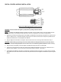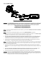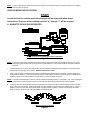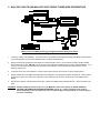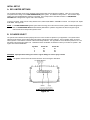
1
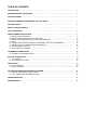
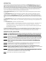
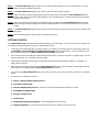
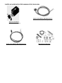
STRIP ANNIHILATOR
Ignition System
Part Number 800-200
Installation Instructions
and Troubleshooting Manual
One or more of the following items may be required to complete the installation of this kit.
820-200 LaserShot Street Ignition Coil
820-100 LaserShot Pro Ignition Coil
820-300 LaserShot ProStrip Ignition Coil
820-101 LaserShot 500 Ignition Coil
821-1 GM HEI Coil In-Cap Adapter Kit
870-400 Tach Signal Amplifier
830-100 Spark Plug Wire Set, 180º Boot
830-110 Spark Plug Wire Set, 90º Boot
830-120 Spark Plug Wire Set, 45º Boot
851-1 HEI External Coil harness
851-3 HEI Bypass harness
NOTE:
These instructions must be read and fully understood before beginning
installation. If this manual is not fully understood, installation should not be
attempted.
Page 1
TABLE OF CONTENTS:
INTRODUCTION .......................................................................................................................................
3
WARNINGS, NOTES, AND NOTICES ......................................................................................................
3
GETTING STARTED .................................................................................................................................
4
PARTS INCLUDED WITH STRIP ANNIHILATOR, P/N 800-200 ............................................................…
5
OPTIONAL PARTS ...................................................................................................................................
6
DIGITAL CONTROL MODULE .................................................................................................................
7
COIL CONNECTIONS ..............................................................................................................................
8
VEHICLE WIRING INSTALLATIONS ........................................................................................................
A. Magnetic Pickup In Distributor ..........................................................................................................
B. Magnetic Pickup Used With Crank Trigger Wheel .............................................................................
C. Mallory Unilite and Mallory Electronic Three Wire Distributors ...........................................................
D. Points ...............................................................................................................................................
E. GM HEI (vacuum advance distributors) and GM HEI (7 wire coil-in-cap distributors) ........................
F. GM HEI (computer controlled external coil distributors) .....................................................................
G. Ford Duraspark and Ford TFI ..........................................................................................................
H. Chrysler Electronic Distributor ...........................................................................................................
9
9
10
12
13
14
15
16
17
TACHOMETER CONNECTIONS ...............................................................................................................
A. Installation of Tach Signal Amplifier ..................................................................................................
18
18
BATTERY CONNECTIONS ........................................................................................................................
A. 12 Volt Parallel .................................................................................................................................
B. 24 Volt Series Connections ...............................................................................................................
19
19
19
INITIAL SETUP .........................................................................................................................................
A. Rev Limit Settings .............................................................................................................................
B. Cylinder Selections ...........................................................................................................................
20
20
20
SETTING THE TIMING AND DISTRIBUTOR PHASING ............................................................................
A. Distributor with Magnetic Pickup or Points .........................................................................................
B. Crank Trigger Wheels With Magnetic Pickup ....................................................................................
21
21
21
TROUBLESHOOTING ...............................................................................................................................
23
SPECIFICATIONS .....................................................................................................................................
24
INTRODUCTION
Holley Performance Products has written this manual for the installation of the STRIP ANNIHILATOR ignition system. This
manual contains all the information needed to install this system. Please read all the WARNINGS, NOTICES, NOTES and
TIPS, they contain valuable information that can save you time and money. It is our intent to provide the best possible products
for our customer; products that perform properly and satisfy your expectations. Should you need information or parts assistance,
please do not return the unit to the store without first contacting technical service at 1-270-781-9741, Monday through Friday, 7
a.m. to 5 p.m. Central Time. By using this number, you may obtain any information and/or parts assistance that you may
require. Please have the part number of the product you purchased when you call.
The Holley STRIP ANNIHILATOR ignition system is a digitally controlled capacitive discharge ignition system that utilizes a
microprocessor.
The STRIP ANNIHILATOR ignition system holds energy on a capacitor, until the correct time to make a spark. They are
“capacitive discharge” or CD type ignitions, not “inductive” ignitions. It is for this reason a capacitive discharge ignition coil
should be used with the STRIP ANNIHILATOR ignition system. Holley LaserShot ignition coils are designed to achieve the
highest currents and fastest voltage rise times at the spark plug gap, because they are “fast” low inductance and low resistance
coils.
The STRIP ANNIHILATOR ignition system is equipped with advanced features that allow you to program rev limiters (3), RPM
activated switches (2), number of cylinders, 2 or 4 cycle operation, pickup type and retard timing on start up adjustable from 0 to
20 degrees.
The STRIP ANNIHILATOR is comprised of two individual modules;
The Digital Control Module – contains the capacitor, the transformer, and the microprocessor. It generates 135 mJ of
output energy and 525 volts. Can be mounted under the hood, in the passenger compartment, or in the trunk.
The QUICKSHOT Programmer – adjust all settings of the system through the detachable handheld programmer with
LED readout and five foot cable.
The detachable QUICKSHOT Programmer, by way of a two digit LED display, shows the various options which can be
programmed. Scrolling through and changing any of the options is fast and easy and is done in “real time”, meaning changes
made to overrevs or control features are instantaneous, so you can realize the difference the instant you make them.
WARNINGS, NOTES, AND NOTICES:
WARNING! The STRIP ANNIHILATOR ignition system is designed and recommended for automotive and marine use
only. Holley Performance Products disapproves the application of this product in any installation other
than automotive and marine. This product was not designed and must not be used in aircraft systems.
WARNING! As with all electronic devices, when welding on the vehicle, always remove both the positive and negative
leads of the STRIP ANNIHILATOR ignition system from the battery, and remove the Digital Control Module
from the vehicle. This will help prevent possible damage to the ignition system electronic control units.
WARNING! Always turn the ignition switch “off” before connecting or disconnecting the control Module wiring
harness. Failure to turn the switched power “off” may result in damage to the STRIP ANNIHILATOR
ignition system.
WARNING! The ignition system is not waterproof. Do not submerge, splash, or otherwise have the unit come in
contact with water or damage to the STRIP ANNIHILATOR or vehicle may result.
WARNING! Do not use any non- Holley devices that alter the pickup signal to the STRIP ANNIHILATOR ignition
system, (i.e. timing retard Modules, external over-rev Modules, etc.). Use of any non-Holley device with the
STRIP ANNIHILATOR ignition system may result in damage to the ignition system.
WARNING! If you are unsure of the history of your distributor, Holley recommends that the distributor be rebuilt by a
qualified technician or replaced before installing the STRIP ANNIHILATOR ignition system. Failure to use
a properly functioning distributor can result in severe engine damage.
NOTE: Verify the timing of your engine before you begin the installation.
NOTE: The STRIP ANNIHILATOR ignition system will not work with odd-fire engines, such as the GM odd fire V-6 or rotary
engines, such as the Mazda rotary engine.
NOTE: The STRIP ANNIHILATOR ignition system will not work with magneto ignition systems.
NOTE: Holley recommends that the original spark plug type and heat range be used with the STRIP ANNIHILATOR ignition
system. Holley also recommends a spark plug gap of .045” as a starting place. Read the spark plugs before making
changes to your vehicle.
NOTE: Holley recommends that only spiral-wound spark plug wires be used with the STRIP ANNIHILATOR ignition system.
Holley offers high quality spark plug wire sets for 8 cylinder applications. Part numbers are listed on the cover of this
manual.
NOTE: The STRIP ANNIHILATOR ignition system will work with most brands of throttle stops, timers, electronic solenoids, and
delay boxes.
NOTE: Label existing wiring before disconnecting, including all accessories!
GETTING STARTED:
The STRIP ANNIHILATOR is the most advanced ignition system on the market today. So, here are some steps to follow to get
you started in the right direction and to help you understand this manual.
1.
Locate the type of vehicle application you will be needing. For example, if you will be firing from a crank trigger wheel, use
the MAGNETIC PICKUP USED WITH A CRANK TRIGGER WHEEL section of this manual. You will not need any of the
other installations listed under VEHICLE WIRING INSTALLATIONS in the manual.
2.
Get to know the system by reading the manual, determine what options you will be using and if any optional parts, such as a
capacitive discharge coil or spark plug wires are needed.
3.
Label existing wiring before disconnecting, including all accessories! Disconnect both the negative (-) and positive (+)
battery cables at this time.
4.
Never install a crank trigger wheel before the STRIP ANNIHILATOR ignition system is installed. A crank trigger wheel will
be the last item you will install with the STRIP ANNIHILATOR ignition system.
5.
As you install the STRIP ANNIHILATOR, tape off the wires you will not use, this will save some confusion as you install the
system.
6.
The sequence for installing this system is:
A. DIGITAL CONTROL MODULE INSTALLATION
B. COIL WIRE CONNECTIONS
C. VEHICLE WIRING INSTALLATIONS: Choose the one vehicle application that matches your vehicle.
D. TACHOMETER CONNECTIONS
E. BATTERY CONNECTIONS
F. INITIAL SETUP
G. TIMING AND DISTRIBUTOR PHASING: Choose the application for your vehicle
H. TROUBLE SHOOTING: This section will help you solve any minor problems you may encounter.
PARTS INCLUDED WITH STRIP ANNIHILATOR, P/N 800-200:
Digital Control Module 6 Wire Main Harness
P/N 850-100 (Harness Only)
Digital Control Module
P/N 810-110 (Module Only)
Digital Control Module 2 Wire Power Harness
P/N 850-150 (Harness Only)
Miscellaneous Small Parts
OPTIONAL PARTS:
LASERSHOT PRO Coil
P/N 820-100
LASERSHOT PROSTRIP Coil
P/N 820-300
GM HEI Module By-pass Harness
P/N 851-3
LASERSHOT 500 Coil
P/N 820-101
GM HEI Coil-in-cap Adapter Kit
P/N 821-1 P/N
Tach Signal Amplifier
P/N 870-400
LASERSHOT STREET Coil
P/N 820-200
ANNIHILATOR 8mm Plug Wire Set
830-100, P/N 830-110, P/N 830-120
GM HEI External Coil Harness
P/N 851-1
DIGITAL CONTROL MODULE INSTALLATION
Digital Control Module wiring harness and connections
Figure 1
WARNING! Disconnect both the negative (-) and positive (+) battery cables at this time.
NOTE: The Digital Control Module should be mounted in the vehicle, close to a battery source, such as the starter solenoid,
starter relay, or main battery terminal strip fed by a minimum of 8 gauge wire, for maximum energy transfer.
1.
Determine and locate the mounting position of the Digital Control Module in the passenger compartment or under the hood
close to a battery source. Position the Module so that access to the harness connector and end panel is possible and in a
position that will allow air to cool the Digital Control Module.
2.
Using the Digital Control Module as a template, mark and drill 4 holes at the mounting location determined in Step 1.
WARNING! Before drilling or punching a hole in the firewall, make sure that you know what is on the other side to
avoid puncturing equipment such as heater cores, air-conditioning system equipment, hoses, or wiring.
3.
Using four bolts (not supplied), mount the Digital Control Module through the holes in the base plate.
4.
Connect the 4 wire harness and six wire main harness to the Digital Control Module. Be sure to use a liberal amount of
dielectric grease supplied. Do not connect the two wire power harness at this time. See Figure 1.
5.
If the Digital Control Module is mounted in the passenger compartment locate an opening in or create a hole in the firewall
that will allow the six wire main harness and the two wire power harness from the Digital Control Module to pass through the
firewall.
COIL CONNECTIONS
Ground wire connection for coil using Ford style connector
Figure 4
WARNING! The STRIP ANNIHILATOR ignition system requires a capacitive discharge type ignition coil. Failure to use
a capacitive discharge type ignition coil will result in poor performance, coil failure and possible ignition
system or vehicle damage. The following coils are recommended for use with this ignition system:
LaserShot Street Coil, Holley Part Number 820-200
LaserShot Pro Coil, Holley Part Number 820-100
LaserShot ProStrip Coil, Holley Part Number 820-300
LaserShot 500 Coil, Holley Part Number 820-101
NOTE: If you are using a GM HEI distributor with vacuum advance, go to the section, GM HEI (vacuum advance distributor)
in this manual.
NOTE: If you are using a Ford Duraspark distributor, go to the section FORD DURASPARK in this manual.
1.
Locate and route the orange and black twisted wire pair of the Digital Control Module to the ignition coil. DO NOT separate
these wires. This helps prevent the chance of outside interference to the ignition system.
2.
Cut to length and crimp a wire terminal (supplied) on the orange wire appropriate for the type coil you will be using. If you
are using the Holley LaserShot Street or Pro coil you will be using a “Ford Style” connector. If you are using the Holley
LaserShot 500 or Pro Strip coil you will be using ring terminals. The correct connectors are supplied with each coil.
3.
The black wire and a short green wire (included in the kit) should be crimped together in one terminal at the coil end as
shown in Figure 4. A ring terminal should be crimped to the other end of the short green wire.
NOTE: The “Ford Style” connector and the coil end are mated and will snap together in one direction only. When inserting the
wires into each of the plug ends be sure that one side of the plug is positive and the other is negative so the plug and
the coil will mate together correctly.
4.
Connect the combined ends of the orange wire of the Digital Control Module and the short green wire to the negative (-)
terminal of the coil. If you are using the “Ford Style” connector insert the wire terminal into the “Ford Style” connector. See
Figure 4.
5.
Connect the orange wire of the Digital Control Module to the positive (+) terminal of the coil. If you are using the “Ford
Style” connector insert the wire terminal into the “Ford Style” connector and insert the connector on to the coil.
6.
Connect the ring terminal end of the short green (16 gauge) wire to a good chassis or engine ground.
WARNING! If your coil is not grounded through the mount to a good chassis ground, such as in a fiberglass body, a
ground wire must be installed from the coil housing to a good chassis ground. Failure to ground the coil
housing could result in an electric shock causing personal injury.
NOTE: In order to get maximum performance from the system, it is important that there is a good connection to the negative
side of the coil and ground.
VEHICLE WIRING INSTALLATIONS:
STOP!
Locate and find the vehicle application that you will be using and follow those
instructions. Only one of the outlined sections “A” through “I” will be required.
A. MAGNETIC PICKUP IN DISTRIBUTOR
Wiring Connections for a Magnetic Pickup in Distributor
Figure 5
NOTE: Follow these instructions for distributors manufactured by companies with an internal magnetic pickup, or if you will
remove the ignition module from the Ford, GM or Chrysler distributor. Holley recommends the computer module be
removed.
1.
Locate and route the violet and green twisted wire pair of the Digital Control Module to the distributor. Keep these wires
routed away from spark plug and coil wires. DO NOT separate these wires.
2.
Cut the violet and green twisted wire pair to length and install the provided female wire terminals. Insert the female wire
terminal with the positive (+) violet wire into the #1 side of the male plastic connector and the female wire terminal with the
negative (-) green wire into the #2 side of the male plastic connector as shown in Figure 6.
NOTE: The male and female plastic connector ends are mated and will snap together in one direction only. When inserting the
wires into each of the plug ends be sure that one side of the plug ends is positive and the other is negative.
3.
Locate the wires from the magnetic pickup in the distributor (see page 10 for a list of common magnetic pickups and their
wiring codes) and cut to length. Install the provided male wire terminals to the wires from the magnetic pickup. Insert the
positive (+) wire into the #1 side of the female plastic connector and the negative (-) wire into the #2 side of the female
plastic connector. Snap the male and female plastic connectors together.
Male and Female Connectors
Figure 6
The following is a list of common magnetic pickups with their wire colors and polarity:
MSD Distributor
Mallory Comp Dist.
GM HEI (Module Removed)
Ford Duraspark (Module Removed)
Chrysler Electronic (Module Removed)
Positive(+)
Orange
Orange
White
Orange
Orange
Negative(-)
Violet
Violet
Green
Violet
Black
NOTE: If your distributor is not listed, the following test can be performed to verify which lead is positive and which is negative.
After completing the installation and programming of the entire system, start the vehicle. Check the ignition timing with
a timing light and note position of the timing marks. Shut the vehicle off and reverse the wires of the magnetic pickup.
Start the vehicle and check the ignition timing. The ignition timing will change by approximately 30º. Connect the
pickup wires to correspond to the ignition timing in the most retarded position. This will be the correct polarity.
4.
Locate and route the red wire of the Digital Control Module to a switched power source. Cut to length and install suitable
wire terminal. Connect the red wire to the switched power source.
5.
Heat shrink or tape the 18 ga. white wire of the Digital Control Module harness. This wire will not be used.
WARNING! DO NOT attempt to start the engine now, you MUST first refer to the sections on INTIAL SETUP and
SETTING THE TIMING AND DISTRIBUTOR PHASING section “A”. Failure to read these two sections
before attempting to start the engine may result in engine damage, property damage, or personal injury in
the event of a backfire.
B. MAGNETIC PICKUP USED WITH A CRANK TRIGGER WHEEL
Magnetic Pickup used with a Crank Trigger Wheel Wiring Connections
Figure 7
NOTE: The Crank Trigger Wheel should be installed AFTER all wiring connections have been made to the Vehicle.
1.
Locate and route the violet and green twisted wire pair of the Digital Control Module to the distributor. Keep these wires
routed away from spark plug and coil wires. DO NOT separate these wires.
2.
Cut the violet and green twisted wire pair to length and install the provided female wire terminals. Insert the female wire
terminal with the positive (+) violet wire into the #1 side of the male plastic connector and the female wire terminal with the
negative (-) green wire into the #2 side of the male plastic connector as shown in Figure 8.
NOTE: The male and female plastic connector ends are mated and will snap together in one direction only. When inserting the
wires into each of the plug ends be sure that one side of the plug ends is positive and the other is negative.
3.
Locate the wires from the magnetic pickup in the distributor (see this page for a list of common magnetic pickups and their
wiring codes) cut to length. Install the provided male wire terminals to the wires from the magnetic pickup. Insert the
positive (+) wire into the #1 side of the female plastic connector and the negative (-) wire into the #2 side of the female
plastic connector. Snap the male and female plastic connectors together.
NOTE: If you have a Holley LASERSTRIKE MAG pickup, the plastic female plug end is already installed and step 3 is not
required.
Male and Female Connectors
Figure 8
The following is a list of common crank trigger magnetic pickups with their wire colors and polarity:
Holley Laserstrike (early model)
Holley Laserstrike (late model)
MSD Crank Trigger
MSD Crank Trigger (old)
Mallory Crank Trigger
FirePower
Moroso
Positive (+)
Black
Violet
Violet
Orange
Violet
Gray or Orange
Black
Negative(-)
White
Green
Green
Black
Green
Black
White
NOTE: If your crank trigger is not listed, the following test can be performed to verify which lead is positive and which is
negative. After completing the installation and programming of the entire system, start the vehicle. Check the ignition
timing with a timing light and note position of the timing marks. Shut the vehicle off and reverse the wires of the
magnetic pickup. Start the vehicle and check the ignition timing. The ignition timing will change by approximately 30º.
Connect the pickup wires to correspond to the ignition timing in the most retarded position. This will be the correct
polarity.
4.
Locate and route the red wire of the Digital Control Module to a switched power source. Cut to length and install suitable
wire terminals. Connect the red wire to the switched power source.
5.
Heat shrink or tape the 18 ga. white wire of the Digital Control Module harness. This wire will not be used.
WARNING! DO NOT attempt to start the engine now, you MUST first refer to the sections on INTIAL SETUP and
SETTING THE TIMING AND DISTRIBUTOR PHASING section “B”. Failure to read these two sections
before attempting to start the engine may result in engine damage, property damage, or personal injury in
the event of a backfire.
C. MALLORY UNILITE AND MALLORY ELECTRONIC THREE WIRE DISTRIBUTORS
Mallory Unilite and Mallory Electronic Three Wire Distributor Wiring Connections
Figure 9
1.
Locate the red wire of the distributor. Connect this wire to any Mallory recommended and approved ballast resistor between
your switched ignition source and the distributor using 12 gauge automotive wire.
2.
Route the red wire of the Digital Control Module to a switched ignition source, cut the red wire to length, install a suitable
wire terminal and connect. DO NOT connect this wire in-line between the ballast resistor in step 1 and the distributor. If you
choose to use the same wire lead that was connected to the distributor, connect between the ballast resistor and the
switched power source.
3.
Locate the brown wire of the distributor. Install a ring terminal to this wire and connect to a good chassis ground.
4.
Route the white wire of the Digital Control Module to the distributor, cut to length and install a wire terminal. Install a mating
terminal to the green wire of the points output lead on the distributor and connect to the white wire of the Digital Control
Module.
5.
Heat shrink or tape the violet and green twisted pair of wires of the Digital Control Module harness. These wires will not be
used.
WARNING! DO NOT attempt to start the engine now, you MUST first refer to the sections on INTIAL SETUP and
SETTING THE TIMING AND DISTRIBUTOR PHASING section “A”. Failure to read these two sections
before attempting to start the engine may result in engine damage, property damage, or personal injury in
the event of a backfire.
D. POINTS
Points Wiring Connections
Figure 10
PERFORMANCE TIP:
Holley highly recommends the use of a LASERSTRIKE MAG CRANK TRIGGER to take full
advantage of the accuracy of the microprocessor in all the ANNIHILATOR IGNITION SYSTEMS.
Use of points will result in poor timing and performance.
1.
Remove the condenser from the distributor.
2.
Remove the resistor wire or ballast resistor between your switched ignition source and the positive (+) side of coil. See
Figure 11 for ballast resistor identification.
3.
Locate and route the red wire of the Digital Control Module to a switched power source. Cut to length and install suitable
wire terminals. Connect the red wire to the switched power source.
Ballast Resistor Identification
Figure 11
4.
Route the white wire of the Digital Control Module to the distributor, cut to length and install a wire terminal. Install a mating
terminal to the points output lead on the distributor and connect to the white wire of the Digital Control Module.
5.
Heat shrink or tape the violet and green twisted pair of wires of the Digital Control Module harness. These wires will not be
used.
WARNING! DO NOT attempt to start the engine now, you MUST first refer to the sections on INTIAL SETUP and
SETTING THE TIMING AND DISTRIBUTOR PHASING section “A”. Failure to read these two sections
before attempting to start the engine may result in engine damage, property damage, or personal injury in
the event of a backfire.
E. GM HEI (Vacuum Advance Distributor) AND GM HEI (7 Wire Coil-in-Cap Distributors)
GM HEI Vacuum Advance Distributor
GM HEI 7 Wire Coil-in-Cap Distributor
GM HEI Vacuum Advance Distributor and GM HEI 7 Wire Coil-in-Cap Wiring Connections
Figure 12
WARNING! To use this Capacitive Discharge ignition system, the GM HEI coil in-cap must be removed. A Holley GM
HEI Coil In-Cap Adapter Kit, Part Number 821-1 must be used with a remote mounted capacitive discharge
coil. These instructions are for the use of an external capacitive discharge coil. Holley does not
recommend the use of the stock inductive coil.
NOTE: Follow these instructions if you will retain the HEI module. You must retain the HEI module to utilize the factory
computer timing control. Refer to section MAGNETIC PICKUP IN DISTRIBUTOR, if you will remove the HEI module.
Holley recommends the computer module be removed.
1.
Remove the GM HEI Coil in Cap and install Holley GM HEI Coil In-Cap Adapter Kit, Part Number 821-1. Follow the
instructions provided. After installation there should only be a black, pink and brown wire remaining on the distributor.
2.
Keep the O.E. 4 wire connector connected to the vehicle wiring harness on GM HEI 7 wire Coil-in-Cap distributor.
3.
Route the white wire of the Digital Control Module to the distributor, cut to length and install a wire terminal. Install the
mating terminal to the brown wire of the HEI distributor and connect to the white wire of the Digital Control Module.
4.
Route the red wire of the Digital Control Module to the GM HEI distributor, cut to length and install a wire terminal. Install
the mating terminal to the dark red or pink wire of the HEI distributor and connect to the red wire of the Digital Control
Module.
5.
Locate the black wire of the HEI distributor. Cut to length and install a suitable wire terminal. Connect the black wire to a
good chassis ground.
6.
Heat shrink or tape the violet and green twisted wire pair of the Digital Control Module harness. These wires will not be
used.
WARNING! DO NOT attempt to start the engine now, you MUST first refer to the sections on INTIAL SETUP and
SETTING THE TIMING AND DISTRIBUTOR PHASING section “A”. Failure to read these two sections
before attempting to start the engine may result in engine damage, property damage, or personal injury in
the event of a backfire.
F. GM HEI (Computer Controlled External Coil Distributor)
GM HEI Computer Controlled External Coil Distributor
GM HEI Computer Controlled External Coil Wiring Connections
Figure 13
NOTE: To use this Capacitive Discharge ignition system with a GM computer controlled external coil distributor the Holley GM
External Coil Harness Kit P/N 851-1 must be used. Holley does not recommend the use of the stock inductive coil.
1.
Install Holley GM External Coil Harness Kit P/N 851-1. Follow the instructions provided.
2.
Route the red wire of the Digital Control Module to the adapter harness (P/N 851-1), cut the red wire to length and install a
wire terminal. Install the mating terminal to the red wire of the adapter harness (P/N 851-1) and connect to the red wire of
the Digital Control Module. See Figure 13.
3.
Route the white wire of the Digital Control Module to the white wire of the adapter harness (P/N 851-1), cut to length and
install a wire terminal. Install the mating terminal to the white wire of the adapter harness (P/N 851-1) and connect to the
white wire of the Digital Control Module. See Figure 13.
4.
Heat shrink or tape the violet and green twisted wire pair of the Digital Control Module harness. These wires will not be
used.
WARNING! DO NOT attempt to start the engine now, you MUST first refer to the sections on INTIAL SETUP and
SETTING THE TIMING AND DISTRIBUTOR PHASING section “A”. Failure to read these two sections
before attempting to start the engine may result in engine damage, property damage, or personal injury in
the event of a backfire.
G. FORD DURASPARK AND FORD TFI
Ford Duraspark
Ford TFI Distributor
Wiring Connection for Ford Duraspark and Ford TFI
Figure 14
NOTE: Follow these instructions if you will retain the ignition module for the Ford Duraspark. You must retain the ignition
module to utilize the factory computer timing control. Refer to section MAGNETIC PICKUP IN DISTRIBUTOR if you
will remove the ignition module. Holley recommends the ignition module be removed.
1.
Locate the old “Ford Style” coil connector that was on the O.E. coil. Cut the coil connector from wiring harness of vehicle.
One of the wires should be dark green/yellow and one should be red/light green. The third wire, if used, is for the tach. If
your wire colors are different, consult a service manual for the correct positive and negative polarity. See Figure 14.
2.
Route the white wire of the Digital Control Module to the O.E. coil wire harness, cut to length and install a wire terminal.
Install the mating terminal to the dark green/yellow wire of the O.E. coil harness and connect to the white wire of the Digital
Control Module. See Figure 14.
3.
Route the red wire of the Digital Control Module to the O.E. coil harness, cut to length and install a wire terminal. Install the
mating wire terminal to the red/light green wire of the O.E. coil harness and connect to the red wire of Digital Control
Module. See Figure 14.
4.
Heat shrink or tape the violet and green twisted pair of wires of the Digital Control module harness. These wires will not be
used.
WARNING!
DO NOT attempt to start the engine now, you MUST first refer to the sections on INTIAL SETUP and
SETTING THE TIMING AND DISTRIBUTOR PHASING section “A”. Failure to read these two sections
before attempting to start the engine may result in engine damage, property damage, or personal injury in
the event of a backfire.
H. CHRYSLER ELECTRONIC DISTRIBUTOR
Chrysler Electronic Distributor
Wiring Connections for Chrysler Electronic Distributor
Figure 15
NOTE: Follow these instructions if you will retain the ignition module. You must retain the ignition module to utilize the factory
computer timing control. Refer to section MAGNETIC PICKUP IN DISTRIBUTOR, if you will remove the ignition
module. Holley recommends the ignition module be removed.
1.
Locate the coil connector that was connected to the O.E. coil. Cut the coil connector from the wiring harness of the vehicle.
One of the wires should be black/yellow and one should be brown as shown in Figure 15. The third wire, if used, is for the
tach. If your wire colors are different, consult a service manual for the correct positive and negative polarity.
2.
Route the white wire of the Digital Control Module to the O.E. coil wire harness, cut to length and install a wire terminal.
Install the mating terminal to the black/yellow wire of the O.E. coil wire harness and connect to the white wire of the Digital
Control Module. See Figure 15.
3.
Route the red wire of the Digital Control Module to the O.E. coil wire harness, cut to length and install a wire terminal. Install
the mating wire terminal to the brown wire of the O.E. coil wire harness and connect to the red wire of Digital Control
Module. See Figure 15.
4.
Heat shrink or tape the violet and green twisted pair of wires of the Digital Control Module harness. These wires will not be
used.
NOTE: If your vehicle is equipped with a ballast resistor, you must by-pass the resistor by using a jumper wire or wire between
the connected terminals.
WARNING! DO NOT attempt to start the engine now, you MUST first refer to the sections on INTIAL SETUP and
SETTING THE TIMING AND DISTRIBUTOR PHASING section “A”. Failure to read these two sections
before attempting to start the engine may result in engine damage, property damage, or personal injury in
the event of a backfire.
Ballast Resistor Identification
Figure 16
TACHOMETER CONNECTIONS
The brown wire of the Digital Control Module wiring harness is a tachometer output wire. The tachometer output is a 12 volt
square wave signal . Make sure your tach uses this type of input signal. Most tachometers manufactured by Autometer,
Mallory, Moroso and VDO use this input type. G.M. and Ford offer some aftermarket tachometers which will work with a 12 volt
square wave input type signal. The remaining tachometer connections must be made in accordance with the tachometer
manufacturers instructions.
If your tachometer does not operate after connecting the tach input lead to the brown wire of the Digital Control Module wiring
harness, and after all other connections are made, your tach signal may not be compatible with the signal from the STRIP
ANNIHILATOR. In this case a Tach Signal Amplifier must be used.
WARNING! DO NOT connect a voltage triggered fuel injection system to a capacitive discharge coil. Connection to a
capacitive discharge coil may result in vehicle electrical system damage.
NOTE: A voltage triggered fuel injection system must be connected to the tach wire of the Digital Control Module. If the fuel
injection system does not operate properly when connected to the Digital Control Module, a tach signal amplifier will
correct the operation of most voltage triggered fuel injection systems that do not work directly off the tach output wire of
the STRIP ANNIHILATOR Digital Control Module.
1.
Route the brown wire of the Digital Control Module to the tachometer, cut to length and install a wire terminal. Install a mating
terminal to the tachometer wire and connect to the brown wire of the Digital Control Module.
NOTE: Most factory-installed tachometers require a Tach Signal Amplifier.
WARNING! DO NOT connect the tach wire of the vehicle to anything other than the yellow tach output lead of the
Digital Control Module harness. Failure to wire the tach properly may result in vehicle electrical system
damage.
A. INSTALLATION OF THE TACH SIGNAL AMPLIFIER
Wiring Connections For Tach Signal Amplifier
Figure 19
1.
Locate the tachometer wire that was disconnected from your vehicle wiring harness or the wire coming from your
aftermarket tachometer. See a service manual if you are unsure of which wire is the tachometer connection.
2.
Connect the violet tach input wire of the tach signal amplifier to the brown wire of the Digital Control Module.
3.
Connect the gray tachometer wire to the aftermarket or factory tachometer lead.
4.
Connect the red wire to a switched power source.
5.
Connect the black wire to a good chassis ground.
BATTERY CONNECTIONS
1.
Route the 12 gauge red and black twisted wire pair of the Digital Control Module harness to the battery. These wires should
go directly to the battery or good battery source for maximum performance.
NOTE: DO NOT untwist the wire pair except for the minimum amount needed for connection to the battery. This helps prevent
the chance of outside interference to the ignition system.
NOTE: The main power connection should be made after the master disconnect switch. If a master disconnect switch is used
always connect the red positive (+) power wire through the switch.
2.
Cut to length the black ground wire (12 gauge) of the twisted wire pair, properly strip the wire and, using an appropriate connector,
connect the wire to the negative (-) side of the battery.
3.
Cut to length the red power wire (12 gauge) of the twisted wire pair, properly strip the wire and, using an appropriate connector,
connect the wire to the positive (+) side of the battery.
NOTE: The STRIP ANNIHILATOR system will operate with 12V to 24V electrical systems. No “Pull Down” switch is required,
see Figures 20 and 21.
A. 12 VOLT PARALLEL CONNECTIONS
1.
Connect the positive (+) battery posts of batteries #1 and #2 together.
2.
Connect the negative (-) battery posts of batteries #1 and #2 together.
3.
Connect the positive (+) vehicle lead to the positive (+) post of battery #2 and the negative (-) vehicle lead to the negative (-)
post of battery #2.
Parallel Connected Batteries
Figure 20
B. 24 VOLT SERIES CONNECTIONS
1.
Connect the positive (+) vehicle lead to the positive (+) post of battery #1.
2.
Connect the negative (-) vehicle lead to the negative (-) post of battery #2.
3.
Connect the negative (-) post of battery #1 to the positive (+) post of battery #2
Series Connected Batteries
Figure 21
INITIAL SETUP
A. REV LIMITER SETTINGS
The rev limiter provides control of the maximum engine speed under various operating conditions. There is on e rev limiter
incorporated in the design of the STRIP ANNIHILATOR ignition system. This feature is always active. The rev limiter drops
sparks when the specified RPM is reached or exceeded. This microprocessor controlled rev limiter is a SEQUENTIAL
PATTERN and is designed for engines under 700 horsepower.
To set the rev limiter, simply turn the rotary switches from 1,000 to 9,900 RPM in 100 RPM increments. For example: “66” equals
6,600 RPM. See Figure 35.
NOTE: The STRIP ANNIHILATOR ignition system will count firings, and in the event the same cylinder would be dropped each
time, the STRIP ANNIHILATOR will automatically alternate the cylinders’ drop pattern to allow the engine to ignite
unburned fuel and to keep all the cylinders clean.
B. CYLINDER SELECT
The cylinder select switches must be properly set for the correct number of cylinders in your application. The cylinder select
switches insure that the overrev switch setting will engage at the proper overrev settings. The four position switch is used to
select cylinders. This switch is to the left of the overrev rotary switches. The up position is on and the down position is off. The
left switch is #2 and the right switch is #1. Listed below is the combination of switches to select your number of cylinders. See
Figure 35 for switch identification.
Cylinders
4
6
8
Switch #1
Off
On
Off
Switch #2
On
On
Off
WARNING! Improper switch setting can result in engine damage or serious injury or death.
NOTE:
The ignition must be turned off and then turned on for the changes to take effect.
STRIP Annihilator Switches
Figure 35
SETTING THE TIMING AND DISTRIBUTOR PHASING
To maximize the accuracy of the STRIP ANNIHILATOR ignition system, Holley recommends triggering the STRIP
ANNIHILATOR ignition system from a magnetic crank trigger wheel. The distributor must be locked out and phased when using
a crank trigger wheel. Locking the advance can be accomplished in a number of ways. Some aftermarket distributors are
designed with a lock out feature. Other distributors may need to have a lock out plate installed or, in extreme cases, the
mechanism can be welded in place. The rotor must be phased to the cap and the magnetic pickup phased to the reluctor. This
may require relocating the magnetic pickup in the distributor housing.
WARNING! Failure to properly modify the distributor may lead to poor performance, damage to the STRIP
ANNIHILATOR ignition system, vehicle and/or engine damage.
WARNING! If you are unsure of the history of your distributor, Holley recommends that a qualified technician rebuild
the distributor before installation. Failure to use a properly functioning distributor can result in severe
engine damage.
A. DISTRIBUTOR WITH MAGNETIC PICKUP OR POINTS
1.
Start the engine.
2.
Using a timing light check the ignition timing with the engine at full advance. DO NOT operate the engine beyond the point
where full advance is reached. If you wish to run a higher degree of advance, loosen the distributor bolt and rotate the
distributor to the advanced timing you intended to use.
3.
Without moving the Distributor, tighten the distributor hold down bracket to complete the timing.
B. CRANK TRIGGER WHEELS WITH MAGNETIC PICKUP
Distributor Phasing
Figure 36
1.
Disconnect the cable between the Digital Control Module and the Magnetic Pickup. This will disable all spark.
2.
Turn the engine over until the distributor and the crank are set at 0° top dead center for the #1 engine cylinder.
3.
Make a mark on the distributor and the engine manifold or block in relation to the rotor pickup. This will allow you to insert
the distributor back to the original location keeping housing in relation to the rotor and the engines cam.
4.
Remove the distributor hold down bolt and remove the distributor to perform the lockout procedures for mechanical
advance, both centrifugal and vacuum. This should be done in the most advanced position.
5.
Insert the distributor back into the motor, be certain that the #1 cylinder top dead center is lined up with the same marks as it
was removed. Tighten distributor bolt.
6.
Using a breaker bar with a socket to match your crank pulley turn the engine over backwards to the most advanced timing
position that you intend to use. For example, if the maximum advance is to be 34 degrees, rotate the engine until the zero
position timing tab lines up with the 34 degree BTDC mark on your balancer. Many aftermarket balancers are engraved
with accurate timing marks. If yours is not, Holley recommends the use of either a degree wheel used in camshaft
installations or a timing tape displaying the degree marks made specifically for your balancer.
7.
Install the block bracket and the crank trigger wheel according to the manufacturer instructions.
8.
With the engine at its most advanced timing position, loosen the distributor bolt and rotate the distributor until the leading
edge of the rotor is aligned with the leading edge of the cap post #1 as shown in Figure 36. Reverse picture for a reverse
rotating distributor. Some racers will drill a small hole, usually 3/8”, in the distributor cap or use a clear distributor cap to
make phasing easier. If you drill a small hole in the cap, plug the hole with a grommet or seal upon completion of phasing.
9.
Adjust the magnetic pickup sensor to align with one of the magnets, on the trigger wheel. Recheck the air gap as per
manufacturers instructions.
10. Re-connect the cable between the Digital Control Module and the Magnetic Pickup. This will enable all spark.
11. Start engine.
12. With the engine at its most advanced timing position, use a timing light and observe the rotor. The rotor should be timed to
match the leading edge of cap post #1 as shown in Figure 36. If required loosen distributor bolt and rotate until it matches
Figure 36. This completes the phasing portion.
13. Check the ignition timing with the engine at full advance. DO NOT operate the engine beyond the point where full advance
is reached. The timing should match the intended timing use. If a slight adjustment is necessary, loosen the sensor bracket
and adjust until the value you intended to use is correct. Any adjustments should be made with the engine off. Recheck the
air gap each time you move the magnetic pickup sensor.
WARNING! Do not attempt to change the position of the magnetic pickup to adjust the ignition timing while the engine
is running. Always shut the engine off while making any adjustments to the location of the magnetic
pickup. Failure to shut the engine off during adjustment may result in vehicle damage, serious injury, or
death!
TROUBLESHOOTING
Problem: System on, but no Spark
Cause:
~ Check connection to coil.
~ Defective Coil - Replace Coil
~ Coil ground defective or poor - Correct ground
~ Poor spark plug ground - ground cylinder heads
~ Low voltage during cranking. Should be greater than 10 volts. Possible causes are excessive timing, defective starter, or
defective or low battery.
~ Weak magnetic pick-up signal. Replace magnetic pickup or adjust air gap to .030”.
~ Defective Digital Control Module. Replace
Problem: Engine starts when key is released from “crank” position
Cause:
~ Low voltage during cranking. Should be greater than 10 volts. Possible causes are excessive timing, effective starter,
or defective or low battery.
~ Defective ignition switch. Replace
Problem: Engine Misfires
Cause:
~ Plug wires not installed on correct spark plugs. Check firing order and repair as necessary.
~ Ignition timing incorrect. Check ignition timing and adjust.
~ Loose connector on wiring harnesses. Check and tighten.
~ Poor connection at battery. Clean connection and reconnect.
~ Improper routing of pick up and coil wires. (wires too close). Re-route wires away from coil wires.
~ See Problem: Engine Misses at high RPM or won’t go over a certain speed.
Problem: Spark Timing too Advanced / Bad Distributor Phasing
Cause:
~ Pickup wires reversed. Reverse pickup wires and recheck timing. If timing retards, leave the pickup wires reversed. If
the timing advances, wire the pickup wires in the previous retarded position.
~ Recheck ignition timing.
~ In crank trigger applications, check distributor phasing.
Problem: Rough Idle / Timing Jumps Around
Cause:
~ Vacuum leak(s). Check and repair all vacuum leaks.
~ Check pickup input wire to make sure that is isolated from black and orange coil wires. Re-route pickup wires away from
coil wires.
~ A/F mixture incorrect. Adjust mixture.
~ Spark plug wire to spark plug connection poor. Check connections and repair as necessary.
~ Defective plug wire. Replace.
~ Spark plug gap incorrect. A good starting gap is .045”. If idle is rough, increase gap in .005” increments until the idle
smoothes.
~ Noise on input. Isolate wiring from other wire noise sources such as plug wires.
~ Poor ground. Clean and reconnect ground.
~ Pick up air gap should be a maximum of .030”.
~ Incorrect phasing on crank trigger wheel. Refer to SETTING THE TIMING AND DISTRIBUTOR PHASING section “B” of
this manual.
~ Defective Digital Control Module. Replace.
Problem: Tachometer not functioning
Cause:
~ Tach output is a 12 volt square wave. Make sure your tach uses this type of input signal. Some tachs require higher
voltages. If your vehicle uses a higher voltage tach input a Tach Signal Amplifier must be used.
~ Check power to tach. Repair.
~ Check tach ground. Clean and reconnect.
~ Check connection between brown tach wire and tachometer input. Repair.
~ Most tachometers manufactured by Autometer, Mallory, Moroso, and VDO do not require a Tach Signal Amplifier.
~ G.M. and Ford offer tachs that do not require a Tach Signal Amplifier.
~ Most factory installed tachs require a Tach Signal Amplifier.
~ Most aftermarket fuel injection systems that connect to the negative side of an inductive coil will require a Tach Signal
Amplifier. Connect only to a tach output wire on a capacitive discharge ignition system.
Problem: Points won’t fire system
Cause:
~ Condenser not removed from circuit. Remove condenser.
~ Defective points. Replace points.
~ Ballast resistor or resistor wire not removed. Remove ballast resistor or resistor wire and replace with 16 gauge
automotive wire.
~ Point gap too large - Adjust to factory specifications.
Problem: Engine runs hot
Cause:
~ Check for correct timing. Adjust if necessary.
~ A/F ratio lean. Adjust mixture.
Problem: Engine misses at high RPM or won’t go over a certain speed
Cause:
~ Check rev limits. Adjust if necessary.
~ Spark plug gap incorrect. Use .045” gap as a starting point. If engine misses at high RPM, decrease gap in .005”
increments.
~ Defective coil. Replace.
~ Battery wiring connections loose or corroded. Clean and tighten.
Problem: Motor loses power during acceleration
Cause:
~ Incorrect timing. Verify timing and adjust if necessary.
~ check distributor for malfunction.
Problem: Ignition system dies unexpectedly
Cause:
~ Switched power interrupted. Check switched power connections.
Problem: Radio noise
Cause:
~ Defective plug wires
SPECIFICATIONS
Multiple sparks/restrikes
Input Voltage:
Average Current Draw:
Maximum Current Draw:
Operating Range:
Output Voltage:
Output Energy:
Tach Output:
Switch Power:
Cylinders
Cycles
Up to 3,000 RPM, 22 1/2 degrees crank rotation
10 - 24 volts DC (negative chassis)
6 amps @ 6000 RPM
40 amps peak
16,000 RPM using 13.8 volt battery
525 volts
135 mJ / spark
12 VDC Square wave
12 to 24 VDC
3,4,6, or 8 (except GM odd fire V-6 and rotary engines)
4
Trigger Inputs:
Magnetic - south pole sensitive negative edge triggered sinusoidal waveform
HEI / Points - zero to 12v square wave
Physical Dimensions:
Mounting bracket holes (center line to center line):
Digital Control Module
L 7.65” X W 2.35”
Housing:
Digital Control Module
L 6.20” X W 4.20” X H 2.55”
Weight:
Digital Control Module
4.55 lbs.
NOTES:
NOTES:
Printed in U.S.A.
Holley
Copyright © 2000
Performance Products Inc
199R-9950
5-8-00
Date: