1
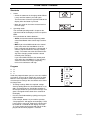
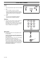
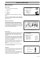
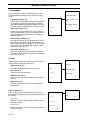
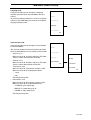
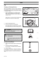
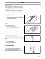
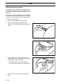
Operator’s Manual
Auto Mower
Please read the Operator’s Manual carefully and make sure you
understand the instructions before using the machine
English
Operator’s Manual for
Auto Mower
Contents
Introduction ................................................ 4
Congratulations .........................................4
Symbols ...................................................... 5
Symbols on Auto Mower ..........................5
Symbols in the Operator’s Manual ............6
Safety instructions...................................... 7
Use ...........................................................7
Transport...................................................8
Maintenance .............................................8
Presentation ................................................ 9
Function Auto Mower ..............................10
Capacity .................................................12
Installation .................................................13
A. Preparations ......................................13
Auto Mower, what is what? ....................14
B. Planning the installation .....................15
C. Placement of the charging station .....20
D. Charging the battery ..........................22
E. Laying out the boundary wire .............22
F. Connecting the boundary wire ...........23
G. Checking the installation ...................25
H. Linking the Auto Mower to the charging
station......................................................25
Control panel .............................................26
Shortcuts .................................................27
Program ................................................27
Section ...................................................28
Numbers .................................................28
Main switch ............................................28
Menu functions ..........................................29
Main menu .............................................29
1. Commands .........................................30
2. Timer ..................................................30
3. Installation ..........................................32
4. Settings ..............................................35
Use .............................................................40
Charging a discharged battery ...............40
Starting the Auto Mower ........................40
Using the timer .......................................41
Stopping the Auto Mower .......................41
Restart ...................................................41
Turning off the Auto Mower ....................41
Adjusting the cutting height ....................42
Maintenance ..............................................43
Battery ....................................................43
Winter Storage .......................................43
Cleaning .................................................44
Replacing the blade units .......................45
Trouble shooting ......................................46
Fault messages ......................................46
Trouble shooting chart ............................48
Technical data............................................49
EU declaration of conformity....................50
Auto Mower Helpdesk
Telephone number: 020 - 77 77 22
Monday - Friday: 8.00 - 20.00
Saturday - Sunday: 12.00 - 16.00
English-3
INTRODUCTION
Introduction
Congratulations
Thank you for purchasing a Husqvarna Auto Mower. The Husqvarna Auto Mower is designed to offer user
friendliness, high operating safety and a long service life. Auto Mower has been built to mow areas that
contain slopes and confined passages as well as many trees and bushes. Using only a minimum of
supervision and maintenance you can have a well-kept lawn throughout the season.
This Operator’s Manual is a valuable document. By following its contents (use, maintenance, etc) you can
contribute towards a long life for the mower and enhance its trade-in value. Read through the Operator's
Manual carefully before you start to install and use your Auto Mower.
Save the Operator’s Manual and, if you sell your Auto Mower, make sure you hand it over to the new owner.
Husqvarna Auto Mower is designed to mow the grass on ordinary lawns free from stones, large branches
and the like. All other types of use are incorrect. The manufacturer’s instructions with regard to driving,
maintenance, and repair must be followed precisely.
WARNING!
Under no circumstances may the original design of the Auto Mower be modified
without the expressed permission of the manufacturer.
Unauthorized modifications and/or components can result in serious disruptions
and the risk of personal injuries.
Always use original spare parts.
English-4
SYMBOLS
Symbols
Symbols on the Auto Mower
These symbols can be found on the lawn mower.
Study them carefully so you understand their significance.
IMPORTANT INFORMATION
Read through the Operator’s Manual carefully
and understand the content before using the
Auto Mower.
1001-003
WARNING
Auto Mower can be dangerous if used
incorrectly.
•
The warnings and safety instructions in the Operator’s Manual must be followed carefully for the
mower to be used safely and efficiently.
1001-002
•
Keep your hands and feet away from the rotating
blades. Never put your hands or feet close to or
under the body of the Auto Mower while it is running.
3012-274
•
Never use the Auto Mower if people, especially children, or pets are nearby.
3012-273
•
This product conforms to the applicable EU Directives.
6001-024
English-5
SYMBOLS
Symbols in the Operator’s Manual
These symbols can be found in the Operator’s Manual.
Study them carefully so you understand their significance.
•
Inspection and/or maintenance should be carried
out with the main switch set to ”OFF”.
OFF
3012-288
•
Always wear protective gloves when working with
the mower’s underframe.
3012-272
•
Never use a high-pressure washer or even running
water to clean the Auto Mower.
3012-271
•
•
The warning box warns of the risk of personal
injury, especially if the instructions are not followed.
The information box indicates the risk of material
damage, especially if the instructions are not followed. The box is also used where there is a risk of
user error.
English-6
WARNING
Xxxx xxxxx xxxx xxxx xxx xxx.
Xxxx xxxxx xxxx xxx xxx xxxx.
IMPORTANT INFORMATION
Xxxxxx xxx xxxx xxxxxxx xxx
xxxx xxxx xxxxx xxx.
SAFETY INSTRUCTIONS
Safety Instructions
Use
•
Read through the Operator’s Manual carefully and
understand the content before using the Auto
Mower.
1001-003
•
Check that there are no stones, branches, tools,
toys or other objects on the lawn that can damage
the blades and cause the mower to stop.
3012-275
•
Start the Auto Mower according to the instructions.
When the main switch is in the ”ON” position; make
sure you keep your hands and feet away from the
rotating blades. Never put your hands and feet
under the mower.
•
Never lift up the Auto Mower or carry it around
when it is running.
•
Do not let persons who do not know how the Auto
Mower works and behaves use the mower.
•
Do not put anything on top of the Auto Mower or its
charging station.
•
Do not allow the Auto Mower to be used with a
defective blade disc or body. Neither should it be
used with defective blades, screws, nuts or cables.
•
Do not use the Auto Mower if the main switch does
not work.
•
Always switch off the Auto Mower using the main
switch when you do not intend to use the mower.
•
The Auto Mower must never be used at the same
time as a sprinkler. In this case use the timer function, see ”2. Timer” on page 30, so the mower and
sprinkler never run simultaneously.
3012-274
English-7
SAFETY INSTRUCTIONS
Transport
The original packaging should be used when transporting the Auto Mower over long distances.
To safely move from or within the working area:
1.
Press the STOP button to stop the mower.
If the stop protection, (see page 36) used as to
prevent theft, has been activated enter the first
number of the PIN-code.
You select the four digit PIN code when you start
the mower for the first time, see page 25.
3012-247
2.
Switch off the main switch if the mower is to be
moved outside of the working area.
3.
Carry the mower by the handle at the rear under
the mower. Carry the mower with the top against
your body.
Maintenance
WARNING
When the mower is turned upside down
the main switch must always be set to
the OFF position.
The main switch should be set to the
OFF position with all work on the
mower’s underframe, such as cleaning
or replacing the blades.
The beeps (5 beeps in 5 seconds) warn
that the blade disc is about to start, if the
beeps are not audible the Auto Mower is
set to sound off.
•
Inspect the Auto Mower each week and replace any
damaged or worn parts.
Check especially that the blades and blade disc are
not damaged. Replace all blade units at the same
time if necessary so that the rotating parts are balanced, see ”Maintenance” on page 43.
English-8
3012-261
ON
OFF
3012-250
PRESENTATION
Presentation
Congratulations on your choice of an exceptionally
high quality product.
To get the best from your Auto Mower requires knowledge of its function. This chapter contains information
you should be aware of when planning the installation.
Installation of the Husqvarna Auto Mower includes four
main components:
Auto Mower, an automatic lawn mower that mows the
lawn by moving in essentially an irregular pattern. The
mower is powered by a maintenance free battery
3012-278
Charging station, where your Auto Mower returns
when the charge level in the battery becomes too low.
The charging station has three functions:
•
To send control signals along the boundary wire.
•
To send out signals so the Auto Mower finds the
charging station.
•
To charge the Auto Mower battery.
3012-216
Transformer, which is connected between the charging station and a 230 V wall socket. The transformer is
connected to the wall socket via an integrated power
cord and to the charging station via a 20 m long low
voltage cable. The length of the low voltage cable must
not be changed.
3012-220
Boundary wire, laid in a loop around the Auto Mower’s
working area. The wire is laid around the edges of the
lawn and around objects and plants that the mower
must not run into.
The length of boundary wire needed in an installation
is the circumference of the working area plus a few
extra metres to lay around ”islands”, objects and
plants. A few extra metres are also required for any
subsequent adjustments. The boundary wire supplied
for the installation is 250 m long. If this is not sufficient
more wire can be purchased, with a connector, and
spliced onto the existing wire.
3012-221
English-9
PRESENTATION
Function Auto Mower
Working method
The Auto Mower automatically mows the lawn. It continuously combines mowing and charging.
When the Auto Mower works on a lawn, it simultaneously stores information about how the garden is
shaped.
The charging station sends out a signal that the Auto
Mower can sense at a distance of 6 - 8 metres. The
mower starts to seek out the charging station when the
capacity of the battery becomes too low. The Auto
Mower does not mow when it is searching for the
charging station.
3012-233
When the battery is charged the mower reverses, turns
around and leaves the charging station in a randomly
selected direction within the exit sector 90°-270°. Both
the reversing length and exit direction can be set, see
”3. Installation” on page 32.
3012-225
When the Auto Mower body hits an obstacle, the
mower reverses and selects a new direction.
Two sensors, front and back on the Auto Mower, sense
when the mower approaches the boundary wire. The
Auto Mower overruns the wire by up to 27 centimetres
before it turns. The overrun length can be set, see
”Drive past wire (3-2)” on page 34.
3012-226
English-10
PRESENTATION
The STOP button on the top of Auto Mower is mainly
used to stop the mower when it’s running. When the
STOP button is pressed a cover opens, behind which
there is a control panel. The STOP button remains
depressed until the cover is closed again. This acts as
start inhibitor.
3012-247
The control panel on the top of the Auto Mower is
where you manage all the mower settings. The main
switch is also located on the control panel. Open the
control panel cover by pressing down the STOP button.
When the main switch is turned ON for the first time, a
start-up sequence begins which includes: selection of
the language, time format, date format and the four
digit PIN code as well as the setting of the time and
date, see page 25.
3012-283
The Auto Mower can enter a sleep mode to save
power. The display on the control panel is then completely dimmed.
The sleep mode is activated 25 minutes after the
STOP button has been pressed and then not reset to
the operating mode. Auto Mower is then activated by
switching the main switch off and on.
The sleep mode can also be activated in the event of a
fault occurring during mowing or charging and which is
not rectified within 25 minutes. The Auto Mower is then
activated by pressing the STOP button.
3012-297
English-11
PRESENTATION
Movement pattern
The mower’s movement pattern is irregular and is
determined by the Auto Mower itself. A movement pattern is never repeated. This mowing system means the
lawn is mown equally without any mowing lines.
3012-276
If the Auto Mower enters an area where it senses the
grass is longer than earlier, it can change the movement pattern. It can then mow in a square pattern to
cover the area of longer grass more systematically.
Thereafter the mower returns to the irregular movement pattern.
3012-277
Capacity
The Auto Mower is recommended for lawns up to
1800 m2.
Auto Mower mows about 75 m2 per hour. How large an
area is mown depends primarily on the condition of the
blades and the type of grass, growth rate and humidity.
The shape of the garden is also significant. If the garden mainly consists of open lawns, the Auto Mower
can mow more per hour than if the garden consists of
several small lawns separated by many trees, flower
beds and passages.
How long the Auto Mower mows respective charges
can vary depending on, among others, the ambient
temperature. Up to about 25°C a fully charged Auto
Mower mows for approximately 60 - 90 minutes,
depending on the age of the battery and the thickness
of the grass. The mower then charges for about 60
minutes. Above 25°C both the mowing and charging
times gradually drop.
English-12
INSTALLATION
Installation
This chapter describes how you install the Auto Mower.
Before starting the installation read the previous chapter ”Presentation” on page 9 to page 12.
The installation should be carried out according to
the following steps:
A.
Preparations.
B.
Planning the installation
C.
Placing the charging station.
D.
Charging the battery.
E.
Laying the boundary wire.
F.
Connecting the boundary wire.
G. Checking the installation
H. Linking the Auto Mower to the charging station.
The letters refer to the following headings.
A. Preparations
1.
If the lawn in the working area is longer than 15
cm mow it using a conventional lawn mower. Then
collect the clippings.
2.
Read carefully through all steps before the installation.
3.
Check that all parts for the installation are
included:
The numbers in brackets refer to the detail diagram ”Auto Mower, what is what?” on page 14.
• Operator’s Manual (22)
• Auto Mower
• Charging station (14)
3012-301
• Boundary wire in the right length (16)
• Transformer (17)
• Low voltage cable (18)
• Staples (19)
• Boundary wire connector (20)
• Boundary wire coupler (21)
During installation you will also need:
• Combination pliers
• Straight spade, if the boundary wire is to be buried
English-13
INSTALLATION
Auto Mower, what is what?
2
6
6
5
9
7
4
3
1
8
13
12
10
11
15
14
17
16
18
19
20
21
22
3012-224
The numbers in the picture corresponds to:
1.
Charging strip
12. Skid plate
2.
Cutting height adjustment cover
13. Blade disc
3.
Front wheel
14. Charging station
4.
Drive wheel
15. LED for operation check of the boundary wire
5.
Body
16. Boundary wire
6.
Stop button
17. Transformer with power cord
7.
Keypad
18. Low voltage cable
8.
Display
19. Staples
9.
Main switch
20. Boundary wire connector
10. Handle
21. Boundary wire coupler
11. Chassis box with electronics, battery and
motors
22. Operator’s Manual
English-14
INSTALLATION
B. Planning the installation
Charging station
First and foremost the charging station should be positioned:
•
Centrally in the main area, along the outer edge
and with a large free area in front of the station.
3012-233
•
In the shadow. The battery is spared if it charged in
the low possible ambient temperature.
•
On relatively level ground. The height difference
must not differ more than 10 cm between the front
and rear of the charging station.
Max 10 cm
Max 10 cm
3012-296
•
Close to a wall socket:
The charging station should be connected to a
230 V wall socket via the low voltage cable and
transformer.
The supplied low voltage cable is 20 metres long.
IMPORTANT INFORMATION
The length of the low voltage cable must not be
changed.
3012-220
3012-223
The transformer must be placed where it is well
ventilated and is not exposed to direct sunlight. It is
also beneficial if the transformer can be placed
under a roof.
It is recommended to use an earth fault-breaker
when connecting the transformer to the wall socket.
English-15
INSTALLATION
Plan the position of the charging station according to
the shape of your garden.
The Auto Mower can be set for one of three basic garden shapes (see page 34).
The Auto Mower works differently depending on the
garden shape the mower has been set to.
The available garden shapes are: open, complex 1 and
complex 2.
The following pictures are examples of the different
garden shapes. The pictures are also good examples
of appropriate charging station placement.
•
The open shape represents a lawn area with few
obstacles and no passages.
2,5
3012-290
3012-291
Example of the open garden shape. Lawn area 400 m2 and 1100 m2
•
Complex 1 is a large lawn area with an average
amount of obstacles and passages.
2,5
3012-292
3012-293
2
2
Example of complex 1 garden shape. Lawn area 900 m respective 1000 m
English-16
INSTALLATION
•
Complex 2 is a large lawn area with many obstacles
and passages.
3012-294
3012-295
2
2
Example of complex 2 garden shape. Lawn area 1500 m respective 800 m
Do not put the charging station in a corner or pocket in
the working area.
3012-235
If the garden consists of two large lawns joined by a
passage, it may be difficult for the Auto Mower to find
the entrance to the passage. Making it difficult to work
efficiently in both areas. One way to make the mower
effectively reach both areas is to position the charging
station in the middle of the passage.
When the charging station needs to be placed in a
passage, is it appropriate to manually set the exit
direction, see ”Charge exit settings (3-1)” on page 32.
This will ensure both areas are mown equally and the
grass close to the charging station will not appear
down trodden.
3012-237
English-17
INSTALLATION
Boundary wire
For a successful installation the placement of the
boundary wire should be planned carefully. Planning is
simplified if you make a sketch of the working area,
including all obstacles. Draw how the boundary wire
should be routed on the sketch.
The boundary wire should be laid so it:
•
Forms a loop around the working area for the Auto
Mower. Only Husqvarna boundary wire ought to be
used. This is tinned and has a high quality insulation
to withstand the dampness in the ground.
•
Is a maximum of 500 metres long.
•
Maintains a maximum distance of 35 metres from
Auto Mower in the entire working area.
•
Does not lie on a sharp incline. The Auto Mower
may find it difficult to reverse back, especially in
damp weather conditions, when there is a large risk
of skidding.
Include the possibility in the planning that adjustments
may need to be made to the loop. In doing so remember:
•
Leave a few extra metres of wire at the beginning
and end, close to the charging station.
•
Place a few extra metres of wire about every 30
metres around the entire loop.
All extra wire should be laid in tight, parallel loops If
staples are used, the parallel loops should be
placed under the same staple.
3012-138
IMPORTANT INFORMATION
Extra wire must not be placed in coils outside
the boundary wire. This can disrupt the Auto
Mower.
3012-281
English-18
INSTALLATION
Remember the following with regard to the working
area boundaries:
•
If a high obstacle, for example a wall or fence, borders the working area, the boundary wire should be
laid 35 cm from the obstacle. This will prevent the
Auto Mower from colliding with the obstacle and
reduce body wear.
35 cm
3012-229
•
If the working area borders against, for example,
pools of water the boundary wire should be supplemented with a fence or the like. The height must
then be at least 10 cm. This will prevent the Auto
Mower, under any circumstances, coming outside
of the working area.
•
If the working area borders against a small ditch, for
example, a flower bed or a small elevation, e.g. a
low verge (3-5 cm), the boundary wire should be
laid 30 cm inside the working area. This prevents
the wheels from driving into the ditch or up onto the
verge.
30cm
3012-228
•
If the working area borders against a flat path or the
like that lies level with the lawn, is it possible to
allow the Auto Mower to run a little over the path.
The boundary wire should then be laid 10 cm from
the edge of the path.
10 cm
3012-230
English-19
INSTALLATION
Remeber the following with regard to the working area
boundaries:
•
The Auto Mower can mow areas with a gradient of
up to 1: 3 (33 cm/m) inside the working area. Areas
that slope more must be demarcated by the boundary wire. If any part of the working area’s outer edge
has a gradient of 1: 5 (20 cm/m) or more, the wire
should be laid inside where the slope starts. The
Auto Mower may find it difficult to turn at the loop
where the ground slopes heavily.
•
Use the boundary wire to demarcate areas inside
the working area, for example, flower beds and
fountains. Lay the cable up to the area, around it
and then return along the same route. If staples are
used, the cable should be laid under the same staple on the return route.
Minimise
3012-108
•
Obstacles that can withstand a collision, for example, trees or bushes higher than 10 cm, do not need
to be demarcated by the boundary wire. The Auto
Mower will turn when it collides with this type of
obstacle.
However, for the most gentle and silent operation, it
is preferable to demarcatee all fixed objects in and
around the working area.
•
Obstacles that slope slightly, for example, stones or
large trees with raised roots, should be demarcated
or removed. The Auto Mower can slide up onto this
kind of obstacle causing the blades to be damaged.
3012-231
Remember the following with regard to secondary
areas and passages:
Secondary area
•
If there are secondary areas close to the main area
the boundary wire should be laid so that these
areas form an ”island” outside of the main area.
Secondary areas are working areas without the
charging station, but which are encircled by the
same boundary wire as the main area. The Auto
Mower must be moved manually between the main
and secondary areas.
If the garden consists of two areas where one area
is much smaller than the other and the areas are
only connected by a very long narrow passage, it
may be suitable to create a secondary area.
English-20
Main area
3012-279
INSTALLATION
•
In order for the loop system to work well, the wires
in passages where the Auto Mower is to run
through must not lie too close together.
Secondary
area
A passage should be at least 2 metres wide so the
Auto Mower can find it and make its way through it.
The minimum spacing between the wires in a passage is 130 cm.
Main area
2m
The transition between a large area and a passage
should be, if possible, designed like a ”funnel”, with
rounded corners, to make it easier for the Auto Mower
to enter the passage.
3012-232
C. Placing the charging station
1.
Place the charging station according to your plan.
2.
Connect the low voltage cable to the charging station.
Only Husqvarna original cable and transformer
may be used.
3012-263
3.
Connect the low voltage cable to the transformer.
The connectors may be a slightly difficult to connect, as they are moisture-proof.
3012-262
4.
Connect the transformer’s power cord to a 230V
wall socket. It is preferable to use an earth-fault
breaker as recommended.
English-21
INSTALLATION
D. Charging the battery
The Auto Mower is supplied with an uncharged battery.
As soon as the charging station is connected, it is possible to charge the mower.
1.
Place the Auto Mower in the charging station to
charge battery while you are laying the boundary
wire.
Charging starts irrespective of the position of the
main switch.
3012-238
From an uncharged state the battery takes about
1 1/2 to 2 1/2 hours until it is fully charged.
If the Auto Mower leaves the charging station
before the boundary wire is connected, the mower
will stop in front of the charging station and show
the fault message ”No loop signal”. This message
automatic clears once the boundary wire is connected.
E. Laying out the boundary wire
1.
Lay the boundary wire according to your plan, but
wait with the connection to the charging station.
Lay the cable by either:
• Securing the cable to the ground with staples.
After a few weeks the grass roots will have
grown over the cable so it is not visible.
It is important to secure the staples close
together. The boundary wire must generally lie
close to the ground so as not to be cut off before
the grass roots have grown over it.
If you intend to install more than one Auto Mower
in the same garden the different installations’
boundary wires can be laid edge to edge with
each other.
3012-221
or:
• Bury the cable at a depth of 2-5 cm (maximum
20 cm).
If the boundary wire is not long enough and
needs to be spliced: Use Husqvarna’s solderless
connector, part number 535 13 37-01. It is waterproof and gives a reliable electrical connection.
To splice: Insert both cable ends in the connector. Then press down the button on top of the
connector.
IMPORTANT INFORMATION
Twisted cables, or a screw terminal (”chockblock”), insulated with insulation tape is not a
satisfactory splice. Soil moisture will cause the
conductors to oxidise and after a while result in
a broken circuit.
English-22
3012-304
3012-305
INSTALLATION
F. Connecting the boundary wire
Connect the boundary wire to the charging station:
1.
Lift up the cover on the charging station:
• Grip under the edge of the cover with both
hands and pull straight out towards the sides.
• Now lift the cover straight up.
3012-268
3012-269
2.
Slide in the ends of the boundary wire in the lowermost holes on the charging station and catch
them in the uppermost holes.
The right hand wire end should be inserted in the
right hand hole and the left hand wire end in the
left hand hole.
3012-266
IMPORTANT INFORMATION
The boundary wire must not be crossed when
connecting to the charging station. Therefore
the right hand wire end must be connected to
the right hand connector on the charging station
and vice versa.
3012-303
English-23
INSTALLATION
3.
Place the cable ends in the connector:
• Open the connector.
• Place the wire in the connector grip.
3012-284
4.
Press the connector together using a pair of pliers.
Press until you hear a click.
3012-264
5.
Cut off any surplus boundary wire. Cut 1-2 cm
above respective connectors.
3012-265
6.
Press the connector onto the metal pin on the
charging station.
IMPORTANT INFORMATION
The right hand connector should be connected
on the right hand metal pin on the charging station and vice versa.
3012-267
English-24
INSTALLATION
7.
Refit the cover on the charging station. Ensure the
three guides on the charging station enter the right
holes in the cover.
3012-270
G. Checking the installation
Check the loop signal by looking to see what indication
the green LED on the charging station is giving.
•
Lit =
the signal is okay.
•
Single flashing every other second =
break in the loop and no signal found.
•
Double flashing every other second =
signal found, but the wire is probably damaged.
Check all wire connections.
3012-282
H. Linking the Auto Mower to the charging
station
1.
Open the control panel cover.
2.
Set the main switch to the ON position.
A start-up sequence begins when the Auto Mower
is started for the first time. The following is
requested: Language, time format, correct time,
date format and correct date.
3.
Place the Auto Mower in the charging station.
4.
State the four digit PIN code. All combinations
except 0000 are permitted.
If you own more than one Auto Mower and charging station in the same garden, each mower must
have its own PIN code.
If you have one Auto Mower for several gardens
with one boundary wire and charging station per
garden the mower can have the same code for all
gardens. The distance between the boundary wire
loops must be at least 20 cm.
When you have chosen a PIN code with the Auto
Mower placed in the charging station, the mower and
charging station are then linked to each other.
English-25
CONTROL PANEL
Control panel
On the top of the Auto Mower there is a control panel
under a cover. Open the cover by pressing the STOP
button. Close the cover by sliding it forward until a click
is heard. The click is heard when the STOP button
returns to the operating mode.
All forms of commands and settings for the Auto Mower
are made via the control panel. All functions are
accessed via a number of menus.
The control panel consists of a display and a keypad.
All information is shown on the display and all entry is
done using the buttons.
3012-283
Huvudmeny
Kommandon
Timer
Installation
Inställningar
3012-285
The main page shows the main menu, cursor, clock,
selected operating mode, number of mowing hours,
clock icon, program selection and battery status.
•
The main menu is the uppermost level in the entire
menu structure.
•
The cursor shows which menu has been selected
when the YES button is pressed.
•
The clock shows the current time.
•
The text AUTO or MAN shows which operating
mode has been selected.
•
The number of operating hours indicates the number of hours since the day of manufacture that the
Auto Mower has been in operation. The time that
the Auto Mower has spent mowing or looking for the
charging station is counted as operating time.
•
The clock icon shows when the Auto Mower should
be or is switched off by the timer, i.e. stands in the
charging station or is on its way to the charging station to switch off.
•
The program icon shows when one of the programs
under the buttons A, B or C is selected.
•
The battery status shows the remaining battery
charge.
The keypad consists of five groups of buttons: Shortcuts, program, selection, numbers and the main switch.
Main menu
Commands
Timer
Installation
Settings
3012-286
Huvudmeny
Kommandon
Timer
Installation
Inställningar
3012-239
English-26
CONTROL PANEL
Shortcuts
1.
Home:
1
• Sends the mower to the charging station. Where
it stays until the button is pressed again.
The house icon is lit on the right-hand side of the
display when the button is pressed.
• Move the cursor in the menu structure back to
the main page.
2.
2
Operating mode:
The selected operating mode is shown on the
right-hand side of the display as AUTO respective
MAN.
3012-240
Press the button to choose between:
• AUTO, the normal automatic operating mode
where Auto Mower mows and charges continuously.
• MAN. If you select MAN and close the control
panel cover when the Auto Mower is on the
lawn, it will mow until the battery is discharged. It
will then stop and show the message ”Battery
empty”. The mower must then be moved manually to the charging station and then started
manually after charging.
If you select MAN and close the control panel
cover when the Auto Mower is in the charging
station the mower will charge completely,
reverse 20 centimetres and stop.
Program
3. A
4. B
5. C
Under the program buttons you can save sets of different settings, to reuse or to simplify the use of an Auto
Mower in several gardens. Under respective buttons
are some preset settings. You can choose to use these
or change them.
•
•
To change settings: Make the required settings.
Save by holding down the selected button for 2 seconds, until two beeps are heard close together. If,
for example, button A is pressed the message ”Program A changed” will be shown for 2 seconds on
the display.
3
4
5
3012-241
Use the saved information by quickly pressing the
required button.
If, for example, button A is pressed the question
”Use program A?” will appear on the display. If YES
is pressed, the message ”Program A selected” will
be shown for 2 seconds on the display. The letter
”A” is then shown on the right-hand side of the display to indicate which program is selected.
English-27
CONTROL PANEL
Select
6.
Clr:
• Press to go back one step in the menu structure.
7.
YES
• Press to confirm an entry or selection.
• Press to start the mower if more than 10 seconds has elapsed since you last pressed a button and you want to close the control panel
cover.
8.
6
8
7
3012-242
Arrows
• Press any of the arrow buttons to browse
between menus or different selections.
Numbers
9.
Used in the menu structure to enter settings, for
example, PIN code, time or exit direction.
Also used to state a number series as a shortcut
to the different menus. See more about number
series in ”Number series” on page 29.
3012-243
Main switch
ON
10. Set the main switch in the ”ON” position to start
the Auto Mower.
Set the main switch in the ”OFF” position when
you are not using the mower or if you want to work
on the blade disc.
When the main switch is set in the ”OFF” position
the motors on the mower cannot start.
When the main switch is turned ON for the first
time, a start-up sequence begins which includes:
selection of the language, time format, date format
and four digit PIN code as well as setting of the
time and date, see page 25.
English-28
OFF
10
3012-244
MENU FUNCTIONS
Menu functions
Main menu
The main menu consists of four options:
1.
Commands
2.
Timer
3.
Installation
4.
Settings
Main menu
Commands
Timer
Installation
Settings
The numbers refer to the headings on the coming
pages.
3012-286
There are a number of submenus under each option.
You can access all the functions to set the Auto Mower
settings via these.
Browse between menus
Browse through the main menu and submenus with
the help of the arrow buttons. Enter values and the
time with the help of the numerical buttons and confirm
each selection with the YES button. Press the Clr-button to move one step back and press the Home button
to return directly to the main menu.
Huvudmeny
Kommandon
Timer
Installation
Inställningar
3012-285
Number series
The selection you have made in the main menu as well
as subsequent selections made in submenus are
shown as a number series in the right hand corner of
the display.
The first number in the series refers to the selection in
the main menu. The second number refers to the first
sub-menu, etc. The displayed number series can consist at most of three numbers.
Day timer
Reset all timers
Start time 1
Stop time 1
Start time 2
Stop time 2
You can use the number series as a shortcut to reach
a specific function directly. For example: Press 2 2 in
the main menu and the sub-menu ”Day timer” is
shown.
00:00
00:00
00:00
00:00
2-2-1
3012-287
The headings on following pages include respective
number series within brackets.
PIN code
Submenus
In some of the submenus there is a box to the right of
specific rows. When this box is checked with a tick it
means the function is selected.
In some of the submenus there is information to the
right of specific rows. This information indicates which
selection has been made for the function.
Time lock
Stop protection
Settings lock
4-13012-307
English-29
MENU FUNCTIONS
1. Commands
Charge then AUTO
Via this selection in the main menu you access the
main Auto Mower functions. Select among the submenus:
Show latest faults
Commands
•
in order for the Auto Mower to drive immediately to
the charging station, charge the battery and then
return to the automatic operating mode. Select the
function and press YES when the cursor is on ”Yes”.
•
factory
set-
Timer
Reset ABC settings
Installation
1-
Show latest faults (1-2)
to show the list of saved fault messages. Browse
with the arrow buttons. The list can contain up to 20
fault messages and each message is shown with
the date and time.
•
Make
tings
Charge then AUTO (1-1)
Settings
Reset factory settings (1-3)
to restore all settings to their original values. Everything except the language, PIN code and the settings under the buttons A, B and C are reset. Select
the function, state your PIN code and press YES
when the cursor is on ”Yes”.
•
Reset ABC settings (1-4)
to delete all programming made under the buttons
A, B and C. Select the function and press YES when
the cursor is on ”Yes”.
2. Timer
Via this option in the main menu you access the timer
settings. Select among the submenus:
•
Timer
Weekend timer
Installation
Week timer
Weekend timer (2-3)
to set the start and stop times for the days Friday Sunday.
•
Day timer
Day timer (2-2)
to set the start and stop times.
•
Commands
Timer override (2-1)
to temporarily disconnect the timer function.
•
Timer override
2-
Settings
Week Timer (2-4)
to select which days of the week the Auto Mower
should mow.
Timer override (2-1)
If you set the timer on your Auto Mower you can use
this function to temporarily get maximal operation from
the mower.
•
OFF
Day timer
ON (2-1-1)
Move the cursor to ”ON” and press YES to turn off
the timer function.
•
ON
Timer override
OFF (2-1-2)
Move the cursor to ”OFF” and press YES to turn on
the timer function.
English-30
Weekend timer
Week timer
2-1
2-1-
MENU FUNCTIONS
Day timer (2-2)
It is possible to set two different start and stop times for
each day. Enter the required time in hours and minutes.
•
Reset all timers (2-2-1)
To delete all set times: Select the function and
press YES when the cursor is on ”Yes”.
•
Start time 1 (2-2-2)
•
Stop time 1 (2-2-3)
•
Start time 2 (2-2-4)
•
Stop time 2 (2-2-5)
Reset all timers
Timer override
Start time 1
Day timer
Stop time 1
Weekend timer
Start time 2
Week timer
2-2
Stop time 2
2-2-
Weekend timer (2-3)
•
Reset all timers
Reset all timers (2-3-1)
To delete all set times: Select the function and
press YES when the cursor is on ”Yes”.
Timer override
•
Start time 1 (2-3-2)
Day timer
•
Stop time 1 (2-3-3)
•
Start time 2 (2-3-4)
•
Stop time 2 (2-3-5)
•
Copy from day timer (2-3-6)
Start time 1
Stop time 1
Weekend timer
Start time 2
Week timer
Stop time 2
Press YES when asked ”Copy?” to transfer all times
set in the day timer.
2-3
Copy from day timer
2-3-
Week Timer (2-4)
Use the YES button to select the days you would like
the Auto Mower to mow.
•
Mon (2-4-1)
•
Tue (2-4-2)
•
Wed (2-4-3)
•
Thu (2-4-4)
•
Fri (2-4-5)
•
Sat (2-4-6)
•
Sun (2-4-7)
•
Run all (2-4-8)
Move the cursor to ”Run all” and press YES. Then
press YES again to the question ”All ON”.
Timer override
Day timer
Mon
Fri
Tue
Sat
Wed
Sun
Thu
Run all
Weekend timer
Week timer
2-4
2-4-
English-31
MENU FUNCTIONS
3. Installation
Via this option in the main menu you access the driving
settings. Select among the submenus:
•
Timer
Charge exit settings (3-1)
to set how far the Auto Mower should reverse out of
the charging station before it turns and in what
direction the mower should leave the charging station.
•
Commands
Drive past wire (3-2)
Installation
Settings
Charge exit settings
Drive past wire
Garden shape
Check loop
3-
to set the distance over the boundary wire that the
Auto Mower should drive.
•
Garden shape (3-3)
to tell the Auto Mower which type of garden you
have.
•
Check loop (3-4)
to check that the loop is intact or exactly where in
the lawn the wire is.
Charge exit settings (3-1)
Normally the Auto Mower leaves the charging station in
a direction within the exit sector 90°-270°, where 90° is
called the begin angle and 270° is called the end angle.
By manually setting the exit direction you can control
how the Auto Mower should leave the charging station.
If the charging station is located in a passage you can
get the best access to all lawns by using this function.
Auto Mower can be set for one or two exit sectors.
3012-225
Use begin and end angle 1 in the menu ”Customized” if
you want to use one sector.
3012-245
English-32
MENU FUNCTIONS
Also use begin and end angle 2 in the menu ”Customized” if you want to use two sectors.
Use the function ”Proportion first” as well to state a
percentage to determine how often the Auto Mower
should leave the charging station in sector 1. For
example, the percentage 75% means the mower will
leave the charging station in sector 1, 75% of the time
and in sector 2, 25% of the time.
3012-246
•
Automatic (3-1-1)
In order for Auto Mower to follow the preselected
exit settings: Move the cursor to ”Automatic” and
press YES. Then press YES again to the question
”Reset to default?”.
Automatic
Charge exit settings
Customized
3-1-
Drive past wire
Garden shape
Check loop
3-1
•
Customized (3-1-2)
Reversing dist.
• Reversing dist.
State the number of centimetres you want the
Auto Mower to reverse before it turns to drive out
of the charging station.
Begin angle 1
Automatic
End angle 1
The default reversing distance is 60 cm.
• Begin angle 1
State in degrees where you want the sector/sector 1 to start.
• End angle 1
State in degrees where you want the sector/sector 1 to end.
Customized
3-1-2
Begin angle 2
End angle 2
Proportion first
• Begin angle 2
State in degrees where you want the sector/sector 2 to start.
• End angle 2
State in degrees where you want the sector/sector 2 to end.
• Proportion first
When you use two exit sectors: State a percentage to define on how many occasions the Auto
Mower should leave the charging station in sector 1.
English-33
MENU FUNCTIONS
Drive past wire (3-2)
Charge exit settings
The front of the Auto Mower always passes the boundary wire by a specific distance before the mower turns.
The default distance is 27 cm, but this can be changed
if required.
Drive past wire
•
Garden shape
To adjust the distance: Move the cursor to ”Drive
past wire” and press YES. Now state the number of
centimetres you want the Auto Mower to pass the
boundary wire.
__
Check loop
3-2
Garden shape (3-3)
The Auto Mower can be set according to three garden
shapes: open, complex 1 and complex 2. See examples of garden shapes on page 16. Many gardens can
be characterised as open, which is also the default setting on the Auto Mower.
•
Open
Drive past wire
Complex 1
Garden shape
Open (3-3-1)
Select ”Open” if your garden has an open lawn, few
obstacles and no passages.
•
Charge exit settings
Complex 2
Check loop
3-33-3
Complex 1 (3-3-2)
Select ”Complex 1” if your garden has an average
number of obstacles and/or passages.
•
Complex 2 (3-3-3)
Select ”Complex 2” if you garden has a large lawn
and many obstacles and/or passages.
Check loop (3-4)
This function allows you to check the mower’s signal
reception from the boundary wire, and to determine
exactly where in the lawn the boundary wire is routed.
The sensor used for this function sits concealed
directly under the catch button for the cutting height
adjustment cover. The sensor detects the position of
the Auto Mower in relation to the loop. ”Inside”, ”Outside” or ”No loop signal” are shown on the display. If
the mower is inside the loop, ”Inside” is shown, etc. If
the mower is set with sound on, a constant beep is also
heard when the mower is outside and a pulsating beep
when it cannot detect a signal. If the mower is inside
the loop no beep is heard.
To:
•
Check the signal reception: Move the cursor to
”Check loop” and press YES.
•
Find wire: Move the Auto Mower over the outer
edge of the working area and select ”Check loop”.
Repeat until you find the boundary between ”Inside”
and ”Outside”. You now know where the wire is.
English-34
Charge exit settings
Drive past wire
Garden shape
Check loop
3-4
MENU FUNCTIONS
4. Settings
Via this option in the main menu you access the available settings. Select among the submenus:
•
Security
Timer
Security (4-1)
to make settings concerning the PIN code, stop
protection, settings lock and alarms. The PIN code
must be stated for the ”Security” menu to be shown.
All security and theft protection functions must be
activated manually when Auto Mower is new.
•
Commands
Sounds
Installation
User info level
Settings
Sounds (4-2)
Language
to adjust the sound level for the functions blade
start-up, operation, charging, fault messages and
keypad.
•
Time and date
4-
User info level (4-3)
to determine the level of detailed for information
shown on the display when Auto Mower is operational.
•
Language (4-4)
to select the menu language.
•
Time and date (4-5)
to set the current time and day as well as the
require time and date format.
Security (4-1)
•
PIN code
PIN code (4-1-1)
Via this function you can change your PIN code at
any time.
• To change the PIN code: Move the cursor to
”PIN code” and press YES. Place the Auto
Mower in the charging station. Enter the new
PIN-code and press YES. Enter the same code
again to confirm and press YES.
When the PIN-code has been changed, the
message ”PIN-CODE CHANGED” is displayed
for a few seconds. The ”Security” menu will then
appear again.
Time lock
Security
Stop protection
Sounds
Settings lock
User info level
4-1-
Language
Time and date
4-1
English-35
MENU FUNCTIONS
•
Time lock (4-1-2)
This function partly involves the Auto Mower stopping to mow after a predetermined number of days
and not continuing until the correct PIN code has
been entered, and partly that the PIN-code must be
entered when the main switch is set to the ON position.
PIN code
Number of
days
Time lock
Stop protection
_ _ days
OFF
To:
• Activate: Move the cursor to ”Time lock” and
press YES. Now Move the cursor to ”Number of
days” and press YES. State how many days you
would like the Auto Mower to mow before it
requests the PIN-code. Finish by pressing YES.
Settings lock
4-1-2
When the chosen number of days have passed,
the Auto Mower completes its mowing, charges
the battery, reverses out of the charging station
and stops. The message ”Enter PIN code” is
shown on the display. You then enter your code
and press YES.
• Deactivate: Move the cursor to ”Time lock” and
press YES. Now move the cursor to ”OFF” and
press YES.
•
Stop protection (4-1-3)
This function entails the first number of the PINcode needing to be stated within 10 seconds after
the STOP button has been pressed. If the correct
number is not entered after three attempts, the
alarm sounds. The alarm can then be stopped by
entering the complete PIN-code.
PIN code
Time lock
ON
Stop protection
OFF
To:
• Activate: Move the cursor to ”Stop protection”
and press YES. Select ”ON” to activate and
press YES. Now respond to the question ”How
many minutes should the alarm sound?”, by stating the number of minutes.
Settings lock
4-1-3
• Deactivate: Move the cursor to ”Stop protection”
and press YES. Select ”OFF” to deactivate and
press YES.
When you select ”OFF”, the alarm function is
also deactivated.
•
Settings lock (4-1-4)
This function prevents any one who does not know
the PIN-code from making or changing any of the
settings. It also prevents the A, B or C programs
from being selected or saved.
To:
PIN code
Time lock
Stop protection
• Activate: Move the cursor to ”Settings lock” and
press YES. Now select ”On” to activate.
• Deactivate: Move the cursor to ”Settings lock”
and press YES. Now select ”Off” to deactivate
the function.
English-36
ON
Settings lock
4-1-4
OFF
_ _ _min
MENU FUNCTIONS
Sounds (4-2)
Default
A number of audio messages are used to indicate what
the Auto Mower is currently doing. The sound levels
are graduated from level 4 (highest) to OFF (completely quiet).
•
All quiet
Sounds
Default (4-2-1)
All high
where the sound level is OFF on all functions
except blade start-up and keypad where the sound
level is set to 2.
• Move the cursor to ”Default” and press YES.
Now press YES when asked ”Set default
sound?”.
•
Security
User info level
Customized
Language
4-2-
Time and date
4-2
All quiet (4-2-2)
means that the sound level for all functions is set to
OFF, except the keypad which is set to sound level
1.
• Move the cursor to ”All quiet” and press YES.
Now press YES to the question ”Set quiet
sound?”.
•
All high (4-2-3)
means all functions are set to sound level 3.
• Move the cursor to ”All high” and press YES.
Then press YES to the question ”Set high
sound?”.
•
Default
All quiet
Blade start-up
All high
Operation
Customized
Charging
Customized (4-2-4)
Use ”Customized” if you wish to set different sound
levels for the different functions.
• To customize: Move the cursor to ”Customized”
and press YES. Now select the respective function, press YES, move the cursor to the required
sound level and finish by pressing YES.
4-2-4
Fault messages
Keypad
When the Auto Mower is set to sounds on, an audio
message is heard according to what the mower is currently doing.
Sounds
Significance
2 beeps/10 seconds
Charging
1 beep/10 seconds
Mowing/searching
1 beep/second for 5 seconds
Starting blade
3 beeps/second
Fault message
On long beep
Blade disc blocked
Short click sound
A button on the keypad has been pressed
Short double beep
A change to the setting has been made
Muffled long beep
Incorrect input
English-37
MENU FUNCTIONS
User info level (4-3)
Selecting the user info level involves determining how
much information should be shown on the display
when the main switch is set in the ON position. The
basic user info level means less information on the display than in the advanced user info level.
Security
Sounds
Basic
User info level
To select:
•
Advanced
4-3-
Basic (4-3-1)
Language
• Move the cursor to ”Basic” and press YES.
•
Advanced (4-3-2)
Time and date
• Move the cursor to ”Advanced” and press YES.
4-3
The table below shows the information messages
shown on respective user info levels.
Information message
Basic user info
level
Advanced user
info level
STARTING
X
X
CHARGING
X
X
Charge time (min)
X
Current charge (mA)
X
MOWING
X
X
Mow time (min)
X
Cutting power
X
SEARCHING
X
X
Mow time (min)
X
Search time (min)
X
TIMER
X
X
FAULT (for example, ”No loop signal”)
X
X
STATE PIN to CANCEL ALARM
X
X
WAITING
X
X
English-38
MENU FUNCTIONS
Language (4-4)
Using this function you can change the language
selection you made when the Auto Mower was first
started.
To select the language: Move the cursor to ”Language”
and press YES. Now Move the cursor to the required
language and press YES.
Security
Sounds
User info level
Language
Time and date
4-4
Time and date (4-5)
Using this function you can change the time and date
on the Auto Mower.
Security
Sounds
You can also change the format selections you made
when the Auto Mower was first started via this function.
•
Set time, 4-5-1
Move the cursor to ”Set time” and press YES. Now
state the correct time and finish with YES.
•
Set time
Language
Set date
Set date, 4-5-2
Move the cursor to ”Set date” and press YES. Now
state the correct date and finish with YES.
•
User info level
Time and date
4-5
Time format
Time format, 4-5-3
Move the cursor to ”Time format” and press YES.
Move the cursor to the required time format:
Date format
4-5-
• 12h or
• 24h.
Finish by pressing YES.
•
Date format, 4-5-4
Move the cursor to ”Date format” and press YES.
Move the cursor to the required date format:
• YY-MM-DD (year-month-day),
• MM-DD-YY (month-day-year) or
• DD-MM-YY (day-month-year).
Finish by pressing YES.
English-39
USE
Use
Charging a discharged battery
When the Auto Mower is new or has been stored for a
long period the battery will not be charged and needs
to be charged before starting. Charging takes between
1 1/2 and 2 1/2 hours.
1.
Place the Auto Mower in the charging station.
Make sure the charging strips on the mower
makes good contact with the contact strips on the
charging station.
3012-238
Good contact is made when both charging strips
lie against the centre of the contact strips.
2.
Open the control panel cover.
3.
Set the main switch to the ON position.
Information about the charging process is shown
on the display during the entire charging process.
3012-299
WARNING
Read the safety instructions before you
start your Auto Mower.
1001-003
WARNING
Keep your hands and feet away from the
rotating blades.
Never put your hands or feet close to or
under the body when the motor is running.
Starting the Auto Mower
1.
Press the STOP button to open the control panel
cover.
2.
Set the main switch to the ON position.
If the time lock is activated: Enter the PIN-code.
3.
3012-274
ON
OFF
Close the cover.
The message ”STARTING” is shown on the display. If
the Auto Mower is set with the sound on you will also
hear 1 beep/second for 5 seconds when blade disc
starts.
3012-244
English-40
USE
Using the timer
Mow the lawn as much as you like when you like. Use
the timer function (see ”2. Timer” on page 30) to avoid
a down trodden lawn and to get the maximum life from
your Auto Mower.
For example, the quality of your lawn will improve if it is
mown every other day instead of 12 hours each day. In
addition, the grass benefits from resting completely
during at least a three day period once a month.
Stopping the Auto Mower
1.
Press the STOP button.
The Auto Mower stops, the blade motor stops and
the control panel cover opens.
3012-247
Restart
Restart within 10 seconds:
1.
Close the control panel cover.
The Auto Mower starts automatically.
3012-248
Restart after more than 10 seconds:
If more than 10 seconds has elapsed since the last
time the STOP button or the keypad was pressed it is
not possible to start the Auto Mower by just closing the
cover.
To start:
1.
Press the YES button.
2.
Close the control panel cover.
3012-302
Turn off Auto Mower
1.
Press the STOP button.
2.
Set the main switch to the OFF position.
Always switch off the Auto Mower using the main
switch if you intend to perform maintenance or move
the mower outside of the working area.
ON
OFF
3012-250
English-41
USE
Adjusting the cutting height
The cutting height is calculated as the distance from
the ground in centimetres. The cutting height can be
varied using 10 different positions from MIN (2 cm) to
MAX (6 cm).
If the grass is long it is appropriate to let Auto Mower
start mowing at the MAX cutting height. Once the grass
is shorter, you can gradually lower the cutting height.
To adjust the cutting height:
1.
Press the STOP button to stop the mower.
2.
Open the cutting height adjustment cover:
Slide the catch button forward and then open the
cover.
3012-251
3012-252
3.
Turn the knob to the required position. The
selected position is the marking on the knob that
aligns with the arrow on the body.
• Turn clockwise to raise the cutting height.
• Turn anticlockwise to lower the cutting height.
3012-253
4.
Close the cover. Ensure that the catch button
locks.
English-42
MAINTENANCE
Maintenance
Check and clean the Auto Mower regularly and replace
worn parts if necessary to improved operating reliability and to give a longer service life.
During the initial period of Auto Mower use the blade
disc, skid plate and blades should be checked once a
week. If the amount of wear during this period has
been low, the inspection interval can be increased.
It is important that the blade disc rotates easily. The
skid plate should rotate easily in relation to the blade
disc. The edges of the blades should not be damaged.
The service life of the blades depends on:
•
Operating time and size of the working area.
•
Type of grass.
•
Type of soil.
•
The presence of objects such as cones, windfalls,
toys, tools, stones, roots and the like.
The service life can vary greatly, but is normally 2-4
weeks of operation over areas larger than 1000 m2
longer in smaller areas.
Battery
The battery is maintenance free, but has a limited life
span of 1-3 years. The battery may only be replaced by
a dealer. Battery life is dependent on the length of the
season and how many hours per day the Auto Mower
is used. A long season or many hours of use per day,
means that the battery must be replaced more regularly.
Winter Storage
Auto Mower:
Clean the Auto Mower carefully and set the main
switch in the ”OFF” position. Store the mower indoors,
in the original packaging, standing on all four wheels.
Charging station:
If possible store the charging station, transformer and
low voltage cable indoors. Remember to protect the
ends of the boundary wire from moisture by placing
them, for example, in a tin with anhydrous grease.
If indoor storage is not possible the boundary wire
should remain connected. The charging station should
remain connected to the mains supply.
After winter storage:
Check whether the Auto Mower, contact strips or
charging strips need to be cleaned before using. If the
charging or contact stripes appear to be burnt, clean
them using fine grade emery cloth. Check that the
mower’s time and date are correct.
English-43
MAINTENANCE
Cleaning
Never use a high-pressure washer or even running
water to clean the Auto Mower.
We recommended a spray bottle with water.
3012-271
Underframe and blade disc
1.
Set the main switch to the OFF position.
2.
Wear protective gloves.
3.
Lift the Auto Mower onto its side.
4.
Clean the blade disc and underframe using, e.g. a
dish-brush.
OFF
3012-288
3012-272
3012-255
3012-256
Body
Use a damp, soft sponge or cloth to clean the body. If
the body is very dirty it may be necessary to use a
soap solution or washing-up liquid.
3012-254
English-44
MAINTENANCE
Replacing the blade units
WARNING
Always use original blade units when
replacing.
Only replacing the blade and reusing the
screw and washer, can result in the
screw wearing during mowing and
shearing off. The blade can then be
thrown causing serious injury.
There are three blade units on the blade disc. Each
unit consists of a screw, a blade and a lock washer.
Always replace all three blade units at the same time,
to obtain a balanced mowing system.
3012-259
1.
Set the main switch to the OFF position.
2.
Wear protective gloves.
OFF
3012-288
3012-272
3.
Turn the Auto Mower upside down.
4.
Rotate the skid plate so that its holes align over
the blade unit screws.
5.
Unscrew the blade unit.
Use a straight slot or cross-tip screwdriver.
3012-260
6.
Pry apart the skid plate and blade disc a little and
remove the blade unit.
7.
Fit the new balde unit.
English-45
TROUBLE SHOOTING
Trouble shooting
Fault messages
A number of fault messages are listed below that can
be shown on the display. If another message than
those listed is shown, contact your dealer.
Fault message
Cause
Action
Left wheel motor
blocked
Grass or other object may have
become wrapped around the drive
wheel.
Check the drive wheel and remove
the grass or other object.
Right wheel motor
blocked
Grass or other object may have
become wrapped around the drive
wheel.
Check the drive wheel and remove
the grass or other object.
Blade disc blocked
Grass or another object may have
become wrapped around the blade
disc.
Check the blade disc and remove the
grass or other object.
No loop signal
Wrong PIN code has been stated.
State the correct PIN code.
The transformer is not connected to
the mains supply or its miniature circuit-breaker has tripped.
Check the wall socket connection and
whether the miniature circuit-breaker
has tripped.
Reset the miniature circuit-breaker by
removing the transformer’s power
cord from the wall socket, wait 10
seconds and then reconnect the
power cord in the wall socket again.
Trapped
English-46
Boundary wire broken.
Check the signal given by the LED on
the charging station. If it flashes the
loop is damaged. Repair the broken
cable using Husqvarna’s waterproof
connector, part number 535 13 37-01.
If this occurs in isolated areas it may
be due to interference from metallic
objects (perimeter fence, reinforcement bar) or buried cables in the
vicinity.
Try to move the boundary wire.
If it occurs in the vicinity of an ”island”
it may be due to the boundary wire be
routed in the wrong direction around
”island” and thereby switching off the
signal.
Check that the boundary wire has
been routed correctly.
Auto Mower has become caught in
something.
Free the Auto Mower and rectify the
reason for it becoming trapped.
TROUBLE SHOOTING
Fault message
Cause
Action
Outside
If this occurs in isolated areas it may
be due to interference from metallic
objects (perimeter fence, reinforcement bar) or buried cables in the
vicinity.
Try to move the boundary wire.
The working area slopes too much.
Check that the boundary wire has
been routed correctly.
The boundary wire has been routed
the wrong way around an ”island”.
Check that the boundary wire has
been routed in accordance with the
installation instructions.
The boundary wire is too close to the
edge of the working area.
Check that the boundary wire has
been routed correctly.
Auto Mower cannot find the charging
station.
Change the position of the charging
station.
The battery is defective.
Contact your dealer to replace the
battery
Wrong PIN code
Wrong PIN code has been entered.
Three attempts are permitted, the
keypad is then blocked for five minutes.
State the correct PIN code.
No drive
Auto Mower has become caught in
something.
Free the mower and rectify the reason
for the lack of drive. If it is due to wet
grass, wait until the lawn has dried
before using the mower.
No contact in charging station
The Auto Mower makes poor contact
with the contact stripes in the charging station.
Check that the Auto Mower has
docked correctly in the charging station.
Charging station
blocked
The contact between the charging
strips and contact strips may be poor
and the Auto Mower has made a
number of charging attempts.
Place the Auto Mower in the charging
station and check that the charging
strips and contact strips make good
contact.
An object is obstructing the Auto
Mower
Remove the object.
Stuck in charging
station
An object is preventing the Auto
Mower from reversing out of the
charging station.
Remove the object.
Upside down
The Auto Mower leans too much or
has turned over.
Turn the mower the right way up.
Empty battery
The Auto Mower is set in MAN operating mode.
This behaviour is normal; no action
required.
Low battery voltage
English-47
TROUBLE SHOOTING
Trouble Shooting Guide
If your Auto Mower does not work correctly, follow the
trouble shooting guide below. If the fault persists; contact your dealer.
Symptom
Cause
Action
Uneven cutting
result
Auto Mower works too few hours per
day.
Increase the mowing time, see ”2.
Timer” on page 30.
Too large working area.
Try to limit the working area or extend
the working time, see ”2. Timer” on
page 30.
Dull blades.
Replace all the blade units so that the
rotating parts are balanced.
Long grass in relation to the set cutting height.
Increase the cutting height. At the
beginning of the season you may
need to mow the lawn the first time
with a conventional lawn mower
before the Auto Mower is put to work.
Grass accumulation by the blade disc
or around the motor shaft.
Check that the skid plate and blade
disc rotate easily. If not, the skid plate
and perhaps the blade disc must be
removed and the grass and foreign
objects removed.
The Auto Mower clock needs to be
set.
Set the clock, see ”4. Settings” on
page 35.
The start and stop times for mowing
are incorrect.
Adjust the start and stop time setting
for mowing, see ”2. Timer” on
page 30.
Auto Mower vibrates
Unbalanced blade disc or damaged
blades.
Inspect the blade units and replace
them if necessary.
Auto Mower runs, but
the blade disc does
not rotate
The Auto Mower is looking for the
charging station.
No action The blade disc does not
rotate when the mower is searching
for the charging station.
The mower mows for
shorter periods than
usual between
charges
Grass or a foreign object is blocking
the blade disc or skid plate.
Dismantle and clean the skid plate
and blade disc.
Both the mowing and
charge times are
shorter than usual
This behaviour is normal in high temperatures (gradually increasing above
25°C).
No action
Auto Mower runs at
the wrong time
English-48
TECHNICAL DATA
Technical Data
Data
Auto Mower
Dimensions
Length
71 cm
Width
56 cm
Height
30 cm
Weight
8.6 kg
Electrical system
Battery
Transformer
NiMH special battery 18V / 2,2 Ah (40 Wh)
230 V / 24 V
Noise emissions
Measured noise level
63 dB(A)
Guaranteed noise level
70 dB(A)
Mowing
Mowing system
Three, pivoted cutting knife blades
Cutting Height
2 -6 cm
Cutting width
22 cm
Working capacity
1800 m2
English-49
EU DECLARATION OF CONFORMITY
EU declaration of conformity
EU Declaration of Conformity (only applies to Europe)
We, Husqvarna AB, SE-561 82 Huskvarna, Sweden, tel: +46-36-146500, declares under sole responsibility that the automatic lawn mower Husqvarna Auto Mower from 2003’s serial numbers and onward
(the year is clearly stated in plain text on the rating plate with subsequent serial number), conforms with
the requirements of the COUNCIL’S DIRECTIVE:
-of June 22, 1998 ”relating to machinery” 98/37/EC, annex IIA.
-of May 3, 1989 ”relating to electromagnetic compatibility” 89/336/EEC, and applicable supplements.
-of May 8, 2000 ”relating to the emission of noise to surroundings” 2000/14/EC.
Information regarding noise emissions and the cutting width, see Technical Data.
The following standards have been applied: EN292-2.
The registered body 0404, SMP Svensk Maskinprovning AB, Fyristorgsgatan 3, SE-754 50 Uppsala,
Sweden, has issued the report with number 01/901/027 regarding the assessment of conformity
according to annex VI to the COUNCIL’S DIRECTIVE of May 8, 2000 ”relating to the emission of noise
to surroundings” 2000/14/EC.
Huskvarna March 6, 2003
Roger Andersson, Development manager
Serial number: ___________________________________
Personal code: ___________________________________
Dealer __________________________________________
Dealer’s telephone number: ________________________
English-50
´®z+H.r¶6]¨
114 01 48-26
´®z+H.r¶6]¨
2003W23