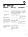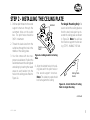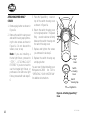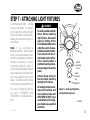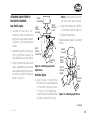
1
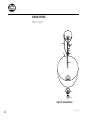
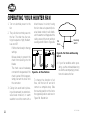
Ye a r - R o u n d C o m f o r t F o r t h e N e x t G e n e r a t i o n
®
Type X
41277-01 05/98
®
CONGRATULATIONS!
Hunter is proud to present the
Whisperwind 2000™ – year-round
comfort for the next generation. This
manual gives you complete instructions for installing and operating your
fan.
• The Speed Ring™ (patent pending) blade attachment system lets
you attach the entire blade assembly in a few simple steps – eliminating the need to attach each
blade to a hanging fan!
All Hunter ceiling fans will provide
comfort and performance in your
home or office for many years. The
Hunter Whisperwind 2000™ also
provides the following features:
• The AirMax™ (patent pending)
motor is quieter, provides better
air flow, and comes with a limited lifetime warranty.
• The new, Hands-Free™ (patent
pending) hanging system makes
wiring the fan even easier.
We at Hunter are proud of our work.
We appreciate the opportunity to
supply you with the best ceiling fan
available anywhere in the world - the
Whisperwind 2000™.
Before installing your fan, record the
following information for your
records and warranty assistance.
Please refer to the carton and the
Hunter nameplate (located on top
outside fan motor housing) for the
proper information.
Model Name __________________
Catalog No. ___________________
Serial No. _____________________
Date Purchased ________________
Where Purchased ______________
_____________________________
Please attach your Hardware Kit and
Parts Drawing to this manual for future reference.
Attach Your Receipt
or a Copy of
Your Receipt Here
© 1998 Hunter Fan Co.
2
41277-01 05/98
®
CONTENTS
Important Information ....................................................................................................................................... 4
Step 1 - Getting Ready ...................................................................................................................................... 5
Step 2 - Installing the Ceiling Plate .................................................................................................................... 7
Step 3 - Assembling the Fan .............................................................................................................................. 9
Step 4 - Wiring the Fan ................................................................................................................................... 11
Step 5 - Hanging the Fan ................................................................................................................................ 13
Step 6 - Attaching Blade Assembly .................................................................................................................. 14
Step 7 - Attaching Light Fixtures ..................................................................................................................... 17
Operating Your Hunter Fan ............................................................................................................................. 22
Troubleshooting .............................................................................................................................................. 23
41277-01 05/98
3
®
IMPORTANT INFORMATION
CAUTIONS
• Read entire booklet carefully before beginning installation.
• To reduce the risk of personal injury, attach the fan
directly to the support
structure of the building
according to these instructions, and use only the
hardware supplied.
• Save these instructions.
WARNINGS
• To avoid possible electrical
shock, before installing
your fan, disconnect the
power by turning off the
circuit breakers to the outlet box and associated wall
switch location. If you can-
4
not lock the circuit breakers in the off position, securely fasten a prominent
warning device, such as a
tag, to the service panel.
• All wiring must be in accordance with national and local electrical codes and
ANSI/NFPA 70- 1993. If you
are unfamiliar with wiring,
you should use a qualified
electrician.
• To reduce the risk of personal injury, do not bend
the Speed Ring™ blade attachment system when installing, balancing, or
cleaning the fan. Never insert foreign objects between rotating fan blades.
• To reduce the risk of fire,
electrical shock, or motor
damage, do not use a solidstate speed control with
this fan. Use only Hunter
speed controls.
DO YOU NEED HELP?
To install a ceiling fan, be sure you
can do the following:
• Locate ceiling joist or other suitable support in ceiling.
• Drill holes for and install wood
screws.
• Identify and connect electrical
wires.
• Lift 40 pounds.
If you need help installing the fan,
your Hunter fan dealer can direct you
to a licensed installer or electrician.
41277-01 05/98
®
STEP 1 - GETTING READY
GATHERING THE TOOLS
PREPARING THE FAN SITE
CHECKING YOUR FAN PARTS
You need the following tools to install the fan:
• Electric drill with 9/64" bit
• Standard screwdriver
• Phillips-head screwdriver
• Wrench or pliers
Reliable operation, efficiency, and
maximum energy savings depend
upon proper placement and attachment of the fan. For this reason, we
have included a separate booklet —
“Guide to Choosing and Preparing
a Ceiling Fan Site” — to help you
select the best location for your fan.
The booklet also provides information to ensure your fan support and
electric outlet box meet UL-approved
safety codes for ceiling fans.
Carefully unpack your fan parts to
avoid damage. Check for shipping
damage. If one of the fan blades is
damaged, return all blades for replacement.
OPTIONAL ACCESSORIES
Consider using Hunter’s optional accessories, such as a wall-mounted or
remote speed control. Follow the instructions for installation and use included with each Hunter accessory.
For quiet and optimum performance
of your Hunter fan, use only Hunter
speed controls.
The instructions in this installation
manual assume that you have used
the “Guide to Choosing and Preparing a Ceiling Fan Site” to pick the
fan location and make certain the
proper fan support and outlet box are
installed.
Hint: If installing more than one fan,
keep the fan blades in sets, as
shipped.
The fan packaging includes a separate diagram of all screws and other
small parts. Keep this diagram handy
during installation.
If any parts are missing or damaged,
contact your Hunter dealer or call the
Hunter Parts Department at 901/
745-9222.
continued
41277-01 05/98
5
®
INSTALLER’S CHOICE ®
This patented 3-position mounting
system gives you maximum flexibility and ease of installation. The steps
in this manual include specific instructions for the fan mounting
method of your choice. For a ceiling
8 feet or higher, standard mounting
is recommended.
Standard Mounting (Figure 1b)
hangs from the ceiling by a connector pipe (included), for ceilings 8 feet
or higher. For ceilings higher than 8
feet, you can also purchase Hunter
extension rods. All Hunter fans use
sturdy 3/4" inner diameter pipe to
assure stability and wobble-free performance.
Flush Mounting (Figure 1a) fits
close to the ceiling, for low ceilings
less than 8 feet high.
6
34° Max
Pitch
12
8
12"
10"
Figure 1a - Flush Mounting
Angle Mounting (Figure 1c) hangs
from a vaulted or angled ceiling.
Figure 1b - Standard Mounting
Figure 1c - Angle Mounting
41277-01 05/98
®
STEP 2 - INSTALLING THE CEILING PLATE
1. Drill two pilot holes into the wood
support structure through the
outermost holes on the outlet
box. The pilot holes should be
9/64" in diameter.
2. Thread the lead wires from the
outlet box through the hole in the
middle of the ceiling plate.
3. Your fan comes with two neoprene noise isolators. Position the
isolators between the ceiling plate
and ceiling by inserting the raised
areas on each isolator into the
holes in the ceiling plate. Refer to
Figure 2a.
Isolators
Ceiling
Plate
For Angle Mounting Only: Be
sure to orient the ceiling plate so
that the two hooks point up towards the ceiling peak as shown
in Figure 2b. Note: You will use
the hooks to support the fan during STEP 5 - WIRING THE FAN.
Figure 2a - Adding Isolators to Ceiling
Plate
4. Align the slotted holes in the ceiling plate with the pilot holes in
the wood support structure.
Note: The isolation pads should
be flush against the ceiling.
Ceiling Plate
Hooks
Figure 2b - Correct Position of Ceiling
Plate for Angle Mounting
continued
41277-01 05/98
7
®
5. Place a flat washer on each of the
two 3" screws and pass the
screws through the slotted holes
in the ceiling plate as shown in
Figure 2c.
6. Tighten the screws into the 9/64"
pilot holes; do not use lubricants
on the screws. Do not overtighten.
Ceiling Joist
2 x 4 Brace
Ceiling
Plate
Flat
Washer
Ceiling
Outlet Box
3" Wood
Screw
Figure 2c - Attaching Ceiling Plate to
2 x 4 Brace
8
41277-01 05/98
®
STEP 3 - ASSEMBLING THE FAN
Follow sub-step 1 below for all fans.
Then, use the additional instructions
for the type of mounting you have
selected: flush, standard, or angle.
ALL FANS
1. Position the fan housing over the
motor hanger adapter. Make sure
the tabs in the motor hanger
adapter fit into the notches in the
housing and that the pipe setscrew (for standard and angle
mounting) passes through the slot
in the housing as shown in Figure 3a.
Flush Mounting
(For Low Ceilings)
1. Fit the canopy over the motor
hanger adapter as shown in Figure 3b. Make sure the canopy fits
snugly against fan assembly with
no space between the pieces.
Assembly
Washer
2. Place the large assembly washer
included with the fan over the
adapter and canopy as shown in
Figure 3b.
3. Position the slots in the assembly
washer over the threaded holes
in the adapter as shown in Figure
3c.
Adapter
Threaded
Hole
Assembly
Washer
Canopy
Adapter
Top of Fan
Figure 3a - Motor Hanger Adapter
Tabs and Housing Notches
41277-01 05/98
Figure 3b - Placing Canopy and
Washer Over Adapter
Figure 3c - Positioning Assembly
Washer Slots Over Threaded Holes
9
®
4. Attach the canopy tightly to the
fan assembly with three #8-32 x
3/4" assembly screws and #8
lockwashers as shown in Figure
3d.
Note: Pipe, ball, and setscrew not
used for flush mounting.
Standard and Angle Mounting
(For 8-foot Ceilings and Higher)
1. Fasten the fan housing to the
motor hanger adapter with three
#8-32 x 3/4" assembly screws and
#8 lockwashers as shown in Figure 3e.
Figure 3d - Attaching Canopy to Fan
Assembly
10
41277-01 05/98
®
STEP 4 - WIRING THE FAN
1. Disconnect the power by turning
off the circuit breakers to the outlet box and associated wall switch
location.
2. Tilt and hang the assembled fan
from the ceiling plate hooks. Slip
two rectangular canopy slots over
ceiling plate hooks as shown in
Figures 4a and 4b.
Note: To hang the fan you must
tilt the canopy to an almost vertical position so the canopy slots
come down over the ceiling plate
hooks.
Ceiling
Plate
Figure 4a - Attaching Slots on Canopy
to Ceiling Plate Hooks
Figure 4b - Assembled Fan Hanging
from Ceiling Plate Hooks
3. You can use either one or two
wall switches to control the fan
and/or lights separately. Use connection 1 on page 12 to
• control the light with a wall
switch and the fan with a
chain pull (one wall switch required)
• control the light with a chain
pull and the fan with a wall
switch (one wall switch required)
• control the light with one wall
switch and the fan with another (two wall switches required)
Use connection 2 on page 12 if
there is no separate wall switch
power wire for the light kit.
Note: Wall switches not included.
continued
41277-01 05/98
11
®
4. Connect the wires as shown in
Figure 4c. To connect the wires,
twist the bare metal leads together. Place a wire nut over the
intertwined length of wire and
twist clockwise until tight as
shown.
Wall Switch Wire For
Separate Control of Light Kit (Note: Wall switch
must be acceptable
as a general-use
Black
Power
switch.)
Wires
In
White
Ceiling
Bare or Green
CAUTION
5. Separate the connected wires by
placing the green and white wires
on one side of the outlet box and
the black and the black/white
wires on the other side of the
outlet box.
6. Turn the connectors upward. Push
the wires gently into the outlet
box.
Outlet Box
2 x 4 Brace
Green Ground
Wire from Ceiling
Plate (present with
standard, angle, and
flush mounting)
Approved
Connectors
Green Ground
Wire from Hanger
Pipe (standard and
angle mounting only)
Ceiling
Plate
1
White
Black
Be sure no bare wire or wire
strands are visible after making connections.
2
Black/White
3 Wires
From Fan
Connections:
1 Connect Blk/Wht Wire from fan
to Wall Switch Wire for separate
control of light, or
2 Connect Blk/Wht Wire from fan
to Ceiling Black Wire if there
is no separate Wall Switch Wire
for the light kit.
Figure 4c - Wiring Diagram
12
41277-01 05/98
®
STEP 5 - HANGING THE FAN
Sub-steps 1 and 2 apply to Flush,
Standard, and Angle mounting. Substep 3 applies to Standard and Angle
mounting only.
1. Swing the fan up so as to align
the canopy screw holes with the
mounting holes on the ceiling
plate. Refer to Figure 5a.
Ceiling
Plate
Groove in
Hanger Ball
2. Install and tighten the two #1032 x 1/2" mounting screws.
3. For Standard and Angle
Mounting only: In addition to
sub-steps 1 and 2, lift the fan
housing towards the ceiling and
rotate the fan until each canopy
tab engages a groove in the
hanger ball as shown in Figure 5b.
Note: If the tabs are already engaged, do not rotate.
Groove in
Hanger
Ball
Canopy
Tab
Figure 5b - Canopy Tabs and Grooves
in Hanger Ball
WARNING
Canopy
Figure 5a - Attaching Canopy to
Ceiling Plate
41277-01 05/98
Failure to complete sub-steps
1 through 3 could cause fan to
fall. (Sub-step 3 not applicable
for flush mounting.)
continued
13
®
STEP 6 - ATTACHING BLADE ASSEMBLY
Hunter’s Speed Ring™ (patent pending) system makes installation easier
than ever by allowing you to put together the entire blade assembly on
your table or workbench, and then
attach it to the fan in just a few,
simple steps. This process eliminates
the need to attach the blades oneby-one to an already hanging fan.
ATTACHING FAN BLADES TO
SPEED RING™
1. Position the blade, medallion, and
Speed Ring™ and insert three #832 x 1/2” oval-head Phillips
screws as shown in Figure 6a.
(Hunter Fans use several types of
decorative medallions.)
Note: Some blades are reversible,
with two different finishes. Make
sure you have selected the preferred finish before proceeding.
14
2. Tighten the screws.
3. Repeat for all blades.
Screw
Decorative
Medallion
Fan Blade
Speed Ring™
(Positioned
Upside Down)
Figure 6a - Attaching Fan Blade to Speed Ring™ Using Decorative Medallion
(Speed Ring™ Positioned Upside Down)
41277-01 05/98
®
ATTACHING SPEED RING™ TO
MOTOR
CAUTION
Make sure that all Speed
Ring™ screws are securely
tightened. Loose screws could
cause noise, improper fan operation, damage to the fan, or
possible injury.
1. Position three grommets in the
cut-out slots in the Speed Ring™
as shown in Figure 6b.
Figure 6c - Attaching Speed Ring™ to
Motor
Figure 6b - Attaching Grommets to
Speed Ring™
2. Lift the Speed Ring™ to the underside of the motor. Align the
two grommet-and-screw combinations from the motor to the
keyhole slots on the Speed Ring™
as shown in Figures 6c and 6d.
3. Place the index finger from your
left hand and the thumb from
your right hand onto the heads
of the two grommet-and-screw
41277-01 05/98
combinations from the motor.
Turn the motor counterclockwise
using the two grommet-andscrew combinations while holding the Speed Ring™ in place as
shown in Figure 6d.
Note: After the screws are tightened, the Speed Ring™ may seem
loose. This is normal and is part
of the Speed Ring™ design to
reduce fan wobble.
Screw
Locations
Note: Make sure that the Speed
Ring™ is not resting on the screw
heads as this may cause some difficulty in turning the motor.
4. Insert and tighten three tapered
head screws as shown in Figure
6d.
Figure 6d - Turning Motor Counterclockwise
continued
15
®
ATTACHING SPEED RING™
COVER
1. Remove plug button as shown in
Figure 6e.
2. Remove the switch housing cover
and switch housing cap by removing the two screws as shown in
Figure 6e. Do not discard the
screws, cover, or cap.
Note: If you are installing a
Hunter light fixture, proceed to
“STEP 7 – ATTACHING LIGHT
FIXTURES.” If you do not wish to
use the integral light fixture, or
purchased a fan without a light
fixture, proceed with sub-steps 36.
3. Place the Speed Ring™ cover on
top of the switch housing cover
as shown in Figure 6e.
4. Return the switch housing cover
to its original position. The Speed
Ring™ cover should now sit firmly
between the switch housing and
the switch housing cover.
5. Replace and tighten the screws
you removed in sub-step 2.
6. Replace the switch housing cap
and plug button.
Speed
Ring™
Cover
You are now finished installing your
Whisperwind 2000™ fan. Turn to
“OPERATING YOUR HUNTER FAN”
for additional instructions.
Switch
Housing
Cover
Switch
Housing Cap
Plug Button
Figure 6e - Attaching Speed Ring™
Cover
16
41277-01 05/98
®
STEP 7 - ATTACHING LIGHT FIXTURES
Your Whisperwind 2000™ fan may
include a light fixture. You may enjoy the fan with or without the light
fixture. Information for wiring and installing all included Hunter light fixtures follows.
Note: If you purchased a
Whisperwind 2000™ without a light
fixture, you may purchase an accessory light kit separately. For best performance and beauty, use only
Hunter-brand light kits, Type A-Z.
Hunter light kits are designed, tested,
and UL approved for all Hunter fans,
and are available at most Hunter
dealers. To install the light kit, follow
the instructions included with the kit.
If you are not installing a light fixture, turn to “OPERATING YOUR
HUNTER FAN” for additional instructions.
41277-01 05/98
WARNINGS
• To avoid possible electrical
shock, before installing
light fixtures, disconnect
power by turning off the
circuit breakers both to the
outlet box and to its associated wall switch location.
If you cannot lock the circuit breakers in the off position, securely fasten a
prominent warning device,
such as a tag, to the service
panel.
• Connect house wiring to
the fan before attaching
the light kit to the fan.
• All wiring must be in accordance with national and
local electrical codes and
ANSI/NFPA 70-1993. If you
are unfamiliar with wiring,
you should use a qualified
electrician.
Switch
Housing
Cover
Switch
Housing
Cap
Plug Button
Figure 7a - Removing Plug Button
and Switch Housing Cover
continued
17
18
41277-01 05/98
®
ATTACHING LIGHT FITTER TO
FAN SWITCH HOUSING
Low-Profile Lights
1. Unscrew the two #6 x 1/2"
mounting screws to remove the
light fixture cover plate as shown
in Figure 7c. Do not discard the
screws.
2. Assemble the switch housing cover
to the light fixture housing. Use
the lockwasher and nut provided.
3. Using the mounting screws from
step 1, assemble the light fixture
cover plate and light fixture housing to the fan switch housing as
shown in Figure 7c.
Note: Be sure to push wire connections up into the switch housing.
Switch
Housing
Light
Fixture
Housing
Switch
Housing
Cover
2. Insert and tighten two #6-32 x
1 1/4" screws. Refer to Figure 7d.
3. Reattach plug button.
Additional steps follow for each light
fixture.
Light
Fixture
Cover Plate
Switch
Housing
Mounting
Screw
Figure 7c - Attaching Low-Profile
Light Fixture
All Other Lights
1. Align the slots in the light fitter
with the chain and reverse switch
on the switch housing as shown
in Figure 7d. The Speed Ring™
cover should sit firmly between the
light fitter and switch housing.
Speed
Ring™
Cover
Light
Fitter
Slot for
Reverse
Switch
Slot for
Chain
Screws
Figure 7d - Attaching Light Fixture
continued
41277-01 05/98
19
®
AURORA FIXTURES
Refer to Figure 7f.
Figure 7f - Aurora Fixtures
20
41277-01 05/98
®
LOW-PROFILE FIXTURES
Refer to Figure 7g.
1. Install bulbs.
2. Insert globe.
3. Install and tighten thumbscrews
manually. Do not overtighten.
Thumbscrew
Globe
Figure 7g - Low-Profile Fixtures
41277-01 05/98
21
®
OPERATING YOUR HUNTER FAN
1. Turn on electrical power to the
fan.
2. The pull chain controls power to
the fan. The chain has four settings in sequence: High, Medium,
Low and Off.
• Pull the chain slowly to change
settings.
• Release slowly to prevent the
chain from recoiling into the
blades.
• The chain uses a breakaway
connector that separates if the
chain is jerked. If this happens,
simply reinsert the chain into
the connector.
3. Ceiling fans work best by blowing air downward (counterclockwise blade rotation) in warm
weather to cool the room with a
22
direct breeze. In winter, having
the fan draw air upward (clockwise blade rotation) will distribute the warmer air trapped at the
ceiling around the room without
causing a draft. Refer to Figure 8a.
Pull
Chain
Reversing
Switch
Figure 8b - Pull Chain and Reversing
Switch
Figure 8a - Air Flow Patterns
4. If your fan wobbles when operating, use the enclosed balancing
kit and the accompanying instructions to balance the fan.
To change the direction of air
flow, turn the fan off and let it
come to a complete stop. Slide
the reversing switch on the fan to
the opposite position as shown in
Figure 8b. Restart fan.
41277-01 05/98
®
TROUBLESHOOTING
PROBLEM
PROBABLE CAUSE
SOLUTION
Nothing happens; fan does not move.
1. Power turned off, fuse blown, or
circuit breaker tripped.
1. Turn power on, replace fuse, or reset breaker.
2. Loose wire connections or wrong
connections.
2. Loosen canopy, check all connections
according to STEP 4 - WIRING THE
FAN (tur n power off before
checking).
3. Motor reversing switch not engaged.
3. Push switch firmly side to side.
4. Pull chain switch not “on.”
4. Pull the pull chain switch.
1. Blade screwed loosely to Speed
Ring™.
1. Tighten screws until snug.
2. Blade cracked.
2. Replace all blades.
3. Using non-approved speed control.
3. Change to approved speed control.
4. Globe screwed loosely to fitter.
4. Hand-tighten the light kit screws.
Ensure that rubber noise isolators
are installed.
Noisy operation.
41277-01 05/98
23
®
PROBLEM
PROBABLE CAUSE
SOLUTION
Excessive wobbling.
1. Unbalanced blades.
1. Use balancing kit included with fan.
Note: When switching from medium
to low speed, you may notice some fan
wobble. When the fan stabilizes at low
speed, wobble will disappear.
2. Loose blades, Speed Ring™, or
blade medallions.
2. Tighten all screws.
3. Fan not secure on hanger assembly.
3. Turn power off, support fan very
carefully, loosen canopy and hang
correctly.
4. Fan hanger ball not seated in
canopy tabs.
4. Turn power off, support the fan
very carefully, and check that the
hanger ball is properly seated.
If you have tried these troubleshooting solutions and still have trouble,
call 901/745-9222 or visit our Web site at http://www.hunterfan.com.
®
24
Hunter Fan Company
2500 Frisco Avenue
Memphis, TN 38114
41277-01 05/98