1
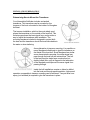
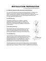
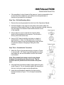
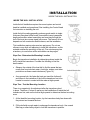
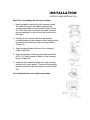
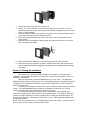
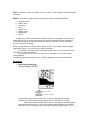
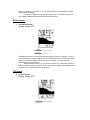
INSTALLATION PREPARATION
PARTS SUPPLIED
PARTS SUPPLIED
Before installing your new Humminbird fishfinder, please ensure the following
parts are included in the box:
•
•
•
•
•
Fishfinder
Transducer with 20’ (6m) of cable and mounting hardware kit
Mounting system and mounting hardware kit
6’ (2m) power cable
Publications kit
It any of these items is missing, call our Customer Support Hotline.
ACCESSORIES
Humminbird offers a wide assortment of accessories that complement and
expand the capability of your new fishfinder. These accessories are designed
with the same high standards and are backed by the same one-year warranty.
The Humminbird Accessory catalog included with your unit contains descriptions
of the many accessories available and ordering information. All Humminbird
accessories are available through your full-service Humminbird dealer or factory
direct through our number listed in the Customer Support section.
INSTALLATION OVERVIEW
Your Humminbird fishfinder consists of two primary components to install: the
control head and the transducer.
The control head contains the sonar transmit and receive circuitry, as well as the
user controls and display. It should be installed in a location that provides access
to the controls and visibility while in use. The control head mounts on a quick
disconnect mounting system that swivels and tilts providing flexibility for viewing
from almost anywhere on the boat.
The transducer converts electrical energy from the transmitter into mechanical
pulses or sound waves. The transducer also receives the reflected sound waves
and converts them back into electrical signals for display on the control head. It
should be installed in contact with the surface of the water in an area that has
smooth waterflow- usually on the transom of the boat. There are several
mounting options for the transducer. Review the following section to determine
the method that works for you and your boat.
INSTALLATION PREPARATION
INSTALLATION OVERVIEW
Determining How to Mount the Transducer
Your Humminbird fishfinder includes a standard
transducer. This transducer can be mounted on the
transom of the boat or bonded to the inside of a fiberglass
hull boat.
The transom installation, which is the most widely used,
places the transducer on the outside of the boat hull. This
technique produces the least signal loss, and provides a
way to adjust the transducer after installation. The
mounting hardware included is designed to protect both
the boat and the transducer should the boat strike debris in
the water or when trailering.
As an alternative to transom mounting, it is possible on
many fiberglass-hulled boats to glue the transducer on
the inside of the boat hull. Since fiberglass has similar
sonar characteristics as water, the sonar signal can
pass through the boat hull with minimal loss. The hull
of the boat must be single layer construction (not
double-hulled) Also, any air trapped in the lamination
of the fiberglass would prevent the sonar signal from
passing through.
Inside the hull installations require no holes be drilled
into the boat and through experimentation, high-speed
operation comparable to transom mounting can be achieved. Two-part slow cure
epoxy (not included) is required to glue the transducer in place.
INSTALLATION PREPARATION
ALTERNATE MOUNTING METHODS
ALTERNATE TRANSDUCERS AND MOUNTING METHODS
Your Humminbird fishfinder comes with everything necessary for installation and
operation on most boats. However, there are several situations which may
require a different type of transducer. Inboard boats, wood or metal hulls, and sail
boats create unique transducer mounting needs Alternate transducers and
mounting methods are detailed below.
Portable Mounting
The standard transducer can be adapted for portable
installations with a portable mounting kit available from
Humminbird. This accessory adapts your transducer to a
suction cup mount for temporary installation on the boat hull
or other surface.
Trolling Motor Mounting
The standard transducer can also be adapted to mount on
most trolling motors using a different accessory kit. This
accessory includes a bracket and hose clamp that allows
mounting the transducer to the body of most trolling motors.
Thru-Hull Mounting
Thru-hull transducers install through a hole drilled in the hull
of the boat. Larger boats or boats with inboard motors create
turbulence that make transom mounting ineffective. Also,
hulls that are very thick or are double layered, or made from
materials such as wood or metal, (which do not conduct
sonar signals) make inside the hull mounting inadvisable.
Thru-hull mounting may require the use of a fairing block to level the transducer
with the waterline. Also, since special tools and knowledge may be required to
perform this type of installation, it is best to refer to a qualified marine technician.
INSTALLATION PREPARATION
TRANSDUCER EXCHANGE
TRANSDUCER EXCHANGE
Other transducers are available as replacements for the standard transducer.
You may exchange your new and unassembled transducer for another type by
returning it to the address listed in Customer Support. Some transducers may
have additional cost. Refer to the Accessory catalog or call Customer Support for
information.
BEGINNING INSTALLATION
Now that you have determined the transducer mounting method you can begin
installation of your new Humminbird fishfinder. The installation guide included on
the next few pages provides detailed step by step instructions for installation of
the control head and transducer. For transom mount transducer installations you
will need the mounting template included with your manual.
In addition to the parts included you need the following for installation and
operation:
•
•
•
•
•
•
•
•
•
A powered hand drill and various drill bits
Philips and flat-head screwdrivers
A ruler or measuring tape
Pen or pencil
12 volt power source (your boat’s battery)
A 1-amp fuse
A fuse holder (if you are wiring directly to the boat’s battery)
Silicone sealant (for sealing drilled holes)
2-part, slow-cure epoxy (for inside the hull transducer installations)
INSTALLATION
TRANSOM INSTALLATION
Do not begin this transducer installation until you read the Installation
Preparation in the Operation Guide. This chapter contains information
critical to the correct installation of your transducer.
Due to the wide variety of boat hulls, only general instructions are
presented in the installation guide. Each boat hull represents a unique set
of requirements that should be evaluated prior to installation.
TRANSOM INSTALLATION
Step One - Determine Where to Mount the Transducer
Begin the transducer installation by determining where on the
transom to install the transducer. Consider the following to find
the best location:
•
It is very important to locate the transducer in an area which is
relatively free of turbulent water, As a boat moves through the
water, turbulence is generated by the weight of the boat, and
the thrust of the propeller(s). This turbulent water is normally
confined to areas immediately aft of ribs, strakes or rows of
rivets on the bottom of the boat, and in the immediate area of
the propeller(s) (Figure 1). On outboard or inboard/outboard
boats it is best to stay at least 15” (40cm) to the side of the
propeller(s).
•
If possible, viewing the transom of the boat while the boat is
moving will provide the best means of locating turbulence free
water. If maximum high-speed operation is a high priority, this
is the recommended method. If this is not possible, select a
location on the transom where the hull forward of this location
is smooth, flat, and free of protrusions or ribs.
•
The transducer when mounted should point straight down.
The design of the transducer will accommodate a wide range
of deadrises and remain ported straight down (Figure 2).
•
On boats with stepped hulls, it may be possible to mount the transducer on
the step. Never mount the transducer on the transom behind a step, as this
area of the transom will not be in contact with the water at high speed (Figure
3).
INSTALLATION
TRANSOM INSTALLATION
•
If the propeller(s) is (are) forward of the transom, it may be impossible to find
an area clear from turbulence, and a different mounting technique or
transducer type should be considered.
Step Two - Drill the Mounting Holes
1. Remove the mounting template from the front of the Operations Manual.
2. Hold the template on the transom of the boat in the location where the
transducer will be installed (Figure 4). Align the template vertically, ensuring
the lower edge of the transom meets with the bottom corner
of the template.
3. Using a pencil or punch, mark the two mounting holes
shown on the template onto the transom. Do not mark or
drill any other holes at this time.
4. Using a 5/32” (4mm) bit drill the two holes to a depth of
approximately 1" (3cm). On fiberglass hulls, it is best to
start with a smaller bit and use progressively larger drill bits
to reduce the chance of chipping or flaking the outer
coating.
Step Three - Assemble the Transducer
1. Attach the Pivot to the transducer body as shown in Figure
5, using the #8 – 3/8” (9mm) long allen headed pivot screw,
the headed pin, the two flat washers, and the two toothed
lock washers.
Note: The toothed lock washers must be positioned
between the transducer and the pivot ears. The flat
washers must be positioned to the outside at the pivot
ears.
2. Using the AIlen wrenches provided, loosely tighten the pivot
screw (Figure 6). Do not completely tighten the assembly at
this time, so the pivot angle can be adjusted later.
3. Insert the pivot/transducer assembly into the mounting
bracket as shown in Figure 7. Do not snap the assembly
closed.
INSTALLATION
TRANSOM INSTALLATION
Step Four - Mount the Transducer to the Transom
1. Apply silicone sealant to the mounting holes drilled into the transom.
2. Align the transducer assembly with the drilled holes in the transom (Figure 8).
3. Use either a flat head screwdriver, a 5/16" (8mm) hex driver, or a 5/16" (8mm)
socket to mount the assembly. Using the two #10 – 1”
(25mm) long slotted hex head screws, mount the transducer
assembly to the transom as shown. Do not fully tighten the
mounting screws in order to vertically adjust the transducer.
Snap the pivot down into place.
Step Five - Adjust the Running Position of the Transducer
The bracket allows height and tilt adjustment, the pivot screws
allow angular adjustment. Initially, adjust the transducer as
described in the following paragraphs. Further adjustment may
be necessary to refine the instillation after high speed testing.
1. First adjust the pivot angle of the transducer body so its
length is parallel with the length of hull of the boat. Then
pivot the transducer down so the rear is about 1/4 inch
(6mm) lower than the front (Figure 9).
2. Fully tighten the two pivot screws using the Allen wrenches.
It may be necessary to retighten the pivot screws after the
initial use as the plastics may still be seating to the lock
washers.
3. Adjust the height of the assembly so the face of the
transducer is 3/16" (4.5mm) beneath the lower edge of the
transom (Figure 10). Mark the position of the mounting
bracket on the transom with a pencil.
4. Force the pivot to the up position to gain access to the
mounting screws. Assure the transducer location has not
changed, then fully tighten the two mounting screws (Figure
11). Snap the pivot back down.
Confirm the pivot angle has not changed.
Note: A third screw location is provided for the
mounting bracket. Drill this hole and install the screw after final testing and
adjustments have been completed.
INSTALLATION
TRANSOM INSTALLATION
Step Six - Route the Cable
There are several ways to route the transducer cable to the to the area where the
control head will be installed. The most common procedure routes the cable
through the transom into the boat.
Inside the boat there is often a channel or conduit used for other
wiring that the cable can be routed along. Do not cut or shorten
the transducer cable and try not to damage the cable insulation.
Route the cable as far as practical from the VHF radio antenna
cables or tachometer cable to reduce the possibility of
interference.
If the cable is too short, extension cables are available to extend
the transducer cable up to a total of 50' (15 m). Call Humminbird
Customer Support for more information.
Follow these steps to route the cable through the transom:
1. Drill a 5/8” (16mm) hole above the water line. Route the
cable through the hole.
2. Fill the hole with silicone sealant.
3. Place the escutcheon plate over the hole and attach with the two #8 x 5/8”
(16mm) screws.
4. Secure the cable by attaching the cable camp to the transom using a #8 x
5/8” (16mm) screw.
Note: The transducer will pivot up to 90 degrees in the bracket. Allow
enough slack in the cable for this movement. It is best to route the cable to
the side of the transducer so the cable will not be damaged by the
transducer during movement.
INSTALLATION
INSIDE THE HULL INSTALLATION
INSIDE THE HULL INSTALLATION
Inside the hull installation requires the mount system and control
head be installed and operational. See Installing the Control Head
for instruction on installing the unit.
Inside the hull mounting generally produces good results in single
thickness fiberglass-hulled boats. Humminbird cannot guarantee
depth performance when transmitting and receiving through the
hull of the boat since some signal loss occurs. The amount of loss
depends on hull construction and thickness, and the installation.
This installation requires slow-cure two-part epoxy. Do not use
silicone or any other soft adhesive to install the transducer, as this
material reduces the sensitivity of the unit. Five minute epoxy has
a tendency to cure before all the air bubbles can be purged.
Step One - Determine the Mounting Location
Begin the transducer installation by determining where inside the
hull to install the transducer. Consider the following to find the
best location:
•
Observe the outside of the boat hull to find the areas that are
mostly free from turbulent water. Avoid ribs, strakes, and other
protrusions as these create turbulence (Figure 14).
•
As a general rule, the faster the boat can travel the further aft
and closer to the centerline of the hull the transducer has to be
located to remain in contact with the water at high speeds.
Step Two - Test the Mounting Location
There is no opportunity for adjustment after the transducer glued
in place. Therefore, it is best to perform a trial installation on inside the hull
transducers first, and run the boat at high speeds to determine the best mounting
area.
1. At the identified mounting location, lay the transducer body face down with
the pointed end towards the bow.
2. Fill the hull with enough water to submerge the transducer body. Use a sand
filled bag or other heavy object to hold the transducer in position.
The transducer cannot transmit through air. The water purges any air from
between the transducer and the hull and fills any voids in the coarse
fiberglass surface.
INSTALLATION
INSIDE THE HULL INSTALLATION
3. Power up the Control Head.
4. Run the boat at various speeds and water depths while observing the screen
on the Control Head. If the unit functions well at low speeds but begins to skip
or miss the bottom at higher speeds, the transducer needs to be moved. If
depth performance is required, test the fishfinder in water at the desired
depth. Test different locations in the hull until the optimum performance is
achieved.
Step Three - Permanently Mount the Transducer
1. Once the mounting location is determined, mark the position of the
transducer.
2. Remove the water from inside the hull and thoroughly dry the
mounting surface. If the surface is excessively rough, it may be
necessary to sand the area to provide a smooth mounting
surface.
Ensure the mounting area is clear and dry.
3. Mix an ample quantity of two-part slow-cure epoxy slowly and
thoroughly. Avoid trapping air bubbles.
4. Coat the face of the transducer and the inside of the hull (Figure
16).
5. Press the transducer into place with a slight twisting motion to
purge any trapped air from underneath, keeping the pointed end
of the transducer body pointed forward (Figure 17).
Note: Proper operation requires the pointed end of the
transducer body to face towards the bow.
6. Weight the transducer so it does not move while the epoxy is curing.
When the epoxy cures, no water is necessary inside the hull. Neither water,
spilled gasoline, or oil will affect the performance of the transducer.
INSTALLATION
CONTROL HEAD INSTALLATION
CONTROL HEAD INSTALLATION
Step One - Determine Where to Mount
Begin the installation by determining where to mount the control head. Consider
the following to determine best location:
•
The cables for power, transducer and temp/speed accessories (if applicable)
should be installed first and must reach the mounting location. Extension
cables are available.
•
There are two ways to route the cables to the unit: through a
hole in the mounting surface underneath the mounting bracket
or from a hole outside the mounting bracket. Routing the cables
down under the mount provides maximum weather protection;
however this is not always feasible if the area under the
fishfinder is inaccessible. In this case, route the cables through
a hole at another location and cover with the supplied hole
cover.
•
The mounting surface should be adequately supported to
protect the fishfinder from excessive wave shock and vibration,
and provide visibility while in operation.
•
The mounting area should allow sufficient room for the unit to
pivot and swivel freely, and for easy removal and installation
(Figures 18-19).
Step Two - Connect the Power Cable to the Boat
A 6’ (2m) long power cable is included to supply power to the
fishfinder. You may shorten or lengthen the cable using 18 gauge
multi-stranded copper wire.
CAUTION: Some boats have 24 or 36 volt electric systems. Be
sure your unit is connected to a 12 VDC power supply.
The Power can be connected to the boat's electrical system at two
places: a fuse panel, usually located near the console, or directly to the battery.
If a fuse terminal is available, use crimp-on type electrical connectors (not
included) that match the terminal on the fuse panel. Attach the black wire to
ground, and the red wire to 12 VDC power (Figure 20). Be sure to use a one amp
fuse in the connection. If you must wire the control head directly to a battery, be
sure to install an inline fuse holder
INSTALLATION
CONTROL HEAD INSTALLATION
and one amp fuse (not included) for the protection of the unit (Figure 21).
Humminbird is not responsible for over voltage or over current failures.
In order to minimize the potential for interference with other
marine electronics a separate power source (such as a
second battery) may be necessary.
Step Three - Drill the Mounting Holes
1. Set the mounting bracket in place on the mounting
surface. Mark the four mounting screw locations with a
pencil or punch.
2. Set the mounting bracket aside, and drill the four
mounting screw holes using a 9/64” (3.6mm) bit.
Step Four - Run the Cables
1. If the cables must pass through a hole underneath the
mounting surface, mark and drill a 1” (25mm) hole
centered between the four mounting holes (Figure 22).
Note: if the cables must pass through the mounting
surface at a different location, drill the 1" (25mm) hole at
that location and pass the cables through from
underneath. Also, you must break out the tabs on the
rear of the mounting base using needle nose pliers
(Figures 24-25).
2. Insert all cables through the 1” (25mm) hole from beneath
the mounting surface.
3. Pass the cables through the grommet (if the cable hole is
underneath the mounting bracket) then press the grommet
in place around the cables and into the 1” (25mm) hole.
4. Pass the cables through the mounting base, out the top of
the mounting bracket.
5. Place the mounting bracket on the mounting surface aligned with the drilled
holes. Insert the four flathead wood screws into the mounting holes and
tighten fully (Figure 23).
Optional: If the cables pass outside the mounting bracket, install the hole
cover over the hole and fasten in place using the two #8 x 7/8” (22mm)
wood screws (Figure 24).
INSTALLATION
CONTROL HEAD INSTALLATION
Step Five - Assembling the Connector Holder
1. Insert the cable connectors into the connector holder.
The cable connectors are labeled, and there are
corresponding labels on the connector holder (Figure
26). The slots for the connectors are keyed to prevent
reverse installation, so do not force the connector into
the holder.
2. Carefully pull the excess cable from beneath the mounting surface so the connector holder aligns with the
mounting holes on the front of the mounting bracket
(Figure 27).
3. Snap the support plate to the rear of the connector
holder (Figure 28).
4. Insert the connector holder into place and use the two
#6-32 x ¾” (9mm) screws to fasten it to the mounting
bracket (Figure 28).
5. Install the control head by sliding it onto the mounting
bracket until it is fully seated. To remove the unit simply
depress the latch on the rear of the unit and lift (Figure
29).
Your Humminbird is now ready for operation.
INSTALLATION
TEST THE INSTALLATION
TEST THE INSTALLATION
Testing should be performed with the boat in the water, however you can initially
confirm basic operation with the boat trailered.
Press POWER once to turn the unit on. There will be an audible chirp when any
button is pressed to confirm the button press. If the unit does not power-up,
ensure the unit is fully seated on the mount and that power is available.
The first screen provides four options: Start-up, Options, Simulator, and
Diagnostic. A message at the bottom of the screen indicates the transducer
connection. If no transducer is detected (or one is not connected), the message
will indicate this and the unit will go into simulator after the initial screen times
out.
Note: the transducer must be submerged in water for reliable transducer
detection.
If a transducer is detected, the unit will enter “Start Up” or normal operation
unless you choose another option. If you do not press any button before the timer
reaches “0”, the normal operation screen is displayed. If the boat is in water,
sonar data appears.
If the bottom is visible on screen with a digital depth readout, the unit is working
properly. Ensure the boat is in water greater than 2’ but less than the depth
capability of the unit and the transducer is fully submerged. Remember the sonar
signal cannot pass through air.
If the unit is working properly gradually increase the boat speed to test highspeed performance. If the unit-functions well at low speeds but begins to skip or
miss the bottom at higher speeds, the transducer requires adjustment. Refer to
the appropriate transducer installation section for more detail.
Note: it is often necessary to make several incremental transducer
adjustments before optimum high-speed performance is achieved.
Important: For Transom Mount transducer installations, install the third mounting
screw after the final transducer adjustments.
Humminbird • 3 Humminbird Lane • Eufaula, Alabama 36027
Installing the SeaScope ID600
Before mounting the SeaScope ID600, gather the parts you need; SeaScope ID600, gimball
mounting bracket, mounting hardware kit, power cable, and transducer cable. If the transducer
cable is not long enough for your installation, see “Accessories” earlier in the manual for
information on the EC-6 10’ extension cable.
Next, consider where to mount the SeaScope ID600. The Gimbal mount allows you to
mount the unit on top of your boat console, or to hang the unit from an overhead structure. Or, by
removing the back of the SeaScope ID600, you can mount the unit flush in a console or bullhead,
by drilling a standard 3-1/2” gauge opening. To choose the best location, consider the following.
• The mounting surface should be adequately supported to protect the SeaScope ID600
from excess wave shock and vibration.
• The mounting area should allow at least 2” clearance at back, sides, and top of the unit
for connection, air flow, and ease of removal.
• Any VHF radio you have may incur some degree of interference with the depth sounder.
SeaRanger depth sounders are designed to minimize this interference, although it is best
to route the transducer cable and antenna cable as far away from each other as possible,
for example, on opposite sides of the boat.
After you have determined the best location for your SeaScope ID600, proceed with the
instructions on the following page.
After installing the transducer, connect the power cable to a 12 VDC power source. It is best
to wire the SeaScope ID600 through your boat’s fuse panel, using a 1-amp fuse and fuse holder
(not included) in the positive wire, as shown on the following illustration. Do not connect
directly to the battery without a fuse. Attach the black lead to the negative (-) terminal, and
wire the red lead through the fuse to the positive (+) terminal. Route the power and transducer
cables to the area you intend to mount the unit, and proceed with the instruction applicable to the
mounting option you have chosen.
Gimbal Mount Installation
1.
2.
3.
4.
5.
6.
7.
Set the gimbal bracket on the mounting surface.
Mark 1/8” holes for the four mounting screws.
At least 3” behind the bracket, mark a 5/8” hole to run the cables through.
Set the gimbal mount aside and drill the holes as marked.
Mount the bracket, using the mounting hardware supplied with you SeaScope ID600.
Pull the transducer and power cables up through the 5/8” hole behind the gimbal brachet,
and connect them to the back of the SeaScope ID600.
Mount the unit on the Gimball and tighten the knobs.
Flush Mount Installation
1.
2.
Remove the bezel of the SeaScope ID600 by gently prying with a coin or scre-driver in
the slot on the bottom side.
Remove the four Phillips-head screws in the corners of the clear plastic lens.
3.
4.
5.
6.
7.
8.
9.
Remove the rear housing and store for future use.
Drill a 3 1/2 “ hole in the dash or console at the location you have chosen. This is a
standard gauge opening size, and hole saws are available at hardware stores, tool rental
stores, or marine dealers.
Place the SeaScope ID600 in the opening, and mark the four mounting holes from which
you removed the screws onto the mounting surface.
Remove the SeaScope ID600 and drill four 1/8” holes in the mounting surface at the
points marked.
Route the power and transducer cables through the opening from behind, and connect
them to the SeaScope ID600.
Fasten the SeaScope ID600 to the mounting surface with the screws provided.
Ensure that the rubber keypad is in position inside the front bezel, and snap the bezel
onto the SeaScope ID600 by engaging the top edge first, then snapping the lower edge
over the lip.
Section 3: Testing the Installation
After installing your SeaScope ID600, transducer, and cables, you should test the
installation. Testing should be performed on the water, since that is the only way to check you
transducer’s performance.
With your boat at idle, press the POWER button to turn the unit on. The SeaScope
ID600 performs a self-test on its electronics, then automatically selects the right depth range and
sensitivity level for conditions. Momentarily, you’ll see the reading start to “march” across the
screen from right to left.
Increase your boat speed to ensure that you get a continuous bottom reading as the boat
moves. Your SeaScopeID600 and its transducer are designed to operate at up to 75 mph.
However, exercise caution when operating any boat at high speed.
If the SeaScope ID600 performs well at idle or slow speeds, but the display is not
continuous at higher speeds, the transducer is not installed properly. Air bubbles or turbulence
from the boat hull are passing across the transducer face, blocking the transmitted signal. By
following the instructions in “Mounting the Transducer,” you can make simple adjustments that
should fix the problem.
NOTE: If the other problems occur, se “Troubleshooting” later in this manual. If you don’t find the
solution there, call our toll-free Customer Service Hotline.
Section 4: Using the SeaScope ID600
This section provides complete information on operating the SeaScope ID600 through its
front panel controls. You are encouraged to read this information completely as you first learn to
use the SeaScope ID600. Doing so will ensure you make the most if it many features and
functions.
The first part of this section explains the use of the built-in simulator, which you can use
to practice selecting functions through the front panel. The remaining instructions, which can be
followed while using the simulator or in actual operation, explain each function and are organized
according to the front panel layout.
Using the Built-In Simulator
The SeaScope ID600 includes a built-in simulator that helps you learn to use your new
equipment. The simulator displays a typical underwater scene, and lets you practive with the
controls.
The unit must be turned off before you start the simulator. To activate it, press down and
hold the POWER button until a chirping sound begins. Release the button, and the built-in
simulator begins displaying a typical SeaScope ID600 reading.
You can use the simulator to learn the functions explained in the following pages, just as
if you were getting actual on-the-water readings. To turn off the simulator, turn off the unit by
pressing the POWER button again.
Of course, the best way to learn the SeaScope ID600 is with actual use, expecially in
familiar waters. If you know what’s below and see it on screen, you’ll quickly become a
SeaScope ID600 expert.
Operating the SeaScope ID600
The SeaScope ID600 offers several functions that you can adjust with the front panel
buttons. (Note that to select something with a button, you must press it fully so that you hear a
“chirp” sound).
You can get acquainted with these features by actual operation, or when using the
simulator.
POWER: Press this once to turn the SeaScope ID600 on. Pressing it again turns the SeaScope
ID600 off. (Any adjustments you make with other front panel buttons are retained, as long as the
12-volt DC pwer supply remains connected). When the unit is off, keeping POWER pressed for
about 2 seconds starts the built-in simulator.
STOP: Press this to “freeze” the display so you can study it. Press it again to restart the display
movement.
SELECT: This button is used to access the following functions for further adjustments:
•
•
•
•
•
•
•
•
Sensitivity/Units
Bottom Alarm
Fish Alarm
Zoom
Bottom Lock
Display Speed
Depth Range
Fish ID
To adjust any of these, press SELECT until the function you want appears. Each function’s
display tells you how to use the arrow buttons and ON-OFF for adjustment; when first learning,
you should also refer tot eh following instructions. After you adjust any function, the display
returns to its full-screen reading.
NOTE: The last function you select remains “active”- that is, you can adjust it without having to
press SELECT again. You can use this to simplify operations.
For example, if the bottom alarm was the last function used, you can readjust the alarm
by pressing one of the arrow buttons.
Or if you often use Zoom, you can select it once, then switch it on and off by simply
pressing ON-OFF.
The following pages describe each funcion, in order of appearance as you first press SELECT.
Sensitivity
1.
Selecting Sensitivity/Units;
Factory setting; +0/FEET
The Sensitivity/Units function has two uses: Its lets you adjust SeaScope ID600
sensitivity and controls whether depth measurement is in feet, fathom, or meters.
The SeaScope ID600 automatically increases or decreases its sensitivity setting
when water conditions change. Ifyou want to manually adjust Sensitivity, select SENS
and press the Up or Down arrow button to adjust the automatic setting with a “+5” to “-5”
range. For example, if you set it at “+2”, Sensitivity remains 2 settings higher that the
normal automatic setting.
Pressing the ON-OFF button when the SENS menu is displayed switches the
unit of depth measurement between feet, fathoms and meters.
Bottom Alarm
2.
Using Bottom Alarm;
Factory setting; OFF
The Bottom Alarm lets you specify the minimum depth you want to maintain. To use it,
select B ALM; then, press the ON-OFF button to activate the alarm, and the Up or Down
arrow key to adjust the depth at which the alarm will sound. An alarm symbol is
displayed when this function is on.
When the Bottom Alarm is on, you’ll hear a continuous chirping sound when the
bottom is shallower than you defined. This is very handy for alerting you to shallow water
or helping you to maintain position over structure.
Fish Alarm
3.
Using Fish Alarm;
Factory setting; OFF
The Fish Alarm alerts you with a chirping sound whenever the SeaScope ID600 detects
fish (or another object not attached to the bottom). To activate it, select FISH ALM and
press the ON-OFF button. A fish symbol reminds you that the alarm is on.
Zoom
4.
Using Zoom;
Factory setting; OFF
Zoom provides an up-close view. To activate it, select Zoom and press ON-OFF. To
activate it, select Zoom and press ON-OFF. The Zoom view initially begins at the
surface; pressing the Up or Down arrow adjusts Zoom depth. The range of the display is
shown when Zoom is on.
The Zoom range depends on the current Depth Range: 3ft in the 6ft and 9ft
Depth Ranges, 5ft in the 15ft and 30ft Depth Ranges, and 10ft in the 45ft to 185ft Depth
Ranges. See Specifications on page 42 for specifications on fathom and meter ranges.
Remember: If Zoom is the last function selected, you can use the arrow button
to adjust the Zoom depth or ON-OFF to switch Zoom on and off without having to press
SELECT first.
Bottom Lock
5.
Using Bottom Lock;
Factory setting; OFF
Bottom-Lock provides an up-close view like Zoom, except that in this case the
zoomed view automatically moves up or down to stay on the bottom. To use this
feature, select BTM LOCK and press ON-OFF. The range of the display is
shown when the Bottom-Lock is on.
This is an ideal feature for finding structure or locating fish near the bottom.
Remember: If Bottom-Lock is the last function selected, you can use the ONOFF button to switch Bottom-Lock on and off without having to press SELECT first.
Display Speed
6.
Setting Display Speed;
Factory setting; One level below maximum
The SeaScope ID600 display is “updated” (advances across the screen)
as you move through the water. The speed at which the display is
updated depends on the Display Speed setting. To adjust it, select
SPEED, and press the Up arrow for a faster setting or the Down arrow for
a slower setting.
In general, higher Display Speed setting provide faster updates, while slower
Display Speeds provide more detailed information.
Depth Range
7.
Setting Depth Range;
Factory setting; On (Automatic)
When you turn the SeaScope ID600 on it finds the bottom, sets the ideal
depth range, and automatically adjusts the depth range (to as much as
480 ft) as the depth changes. In this “Auto Depth Range”mode, the
bottom is blacked-in for easy-to-understand readings.
If you prefer, you can turn Auto Depth Range off. Select RANGE, press ONOFF, and adjust the Depth Range with the UP or Down arrow key. You can set Depth
Range up to 600ft.
In this “Manual Depth Range” mode, the bottom is not blacked in. This lets you
see a “second return,” which is preferred by some fishermen because the width of the
second echo can indicate bottom hardness.
Fish ID
8.
Selecting Fish ID;
Factory setting; On (Automatic)
When you turn the SeaScope ID600 on, the unit automatically sets Fish ID to the On
position. To turn the ID feature off, and display fish with pixels instead of the ID icons,
press the ON-OFF button while within the Fish ID menu. Pressing the ON-OFF button
again reactivates the ID function.