1
HP DL380z Gen8 Virtual Workstation
User Guide
© Copyright 2014 Hewlett-Packard
Development Company, L.P.
The information contained herein is subject
to change without notice. The only
warranties for HP products and services are
set forth in the express warranty statements
accompanying such products and services.
Nothing herein should be construed as
constituting an additional warranty. HP shall
not be liable for technical or editorial errors
or omissions contained herein.
Part number: 768529-001
First Edition: April 2014
Table of contents
1 Abstract ............................................................................................................................................................. 1
2 Component identification .................................................................................................................................. 2
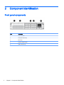
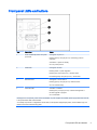
Front panel components ....................................................................................................................... 2
Front panel LEDs and buttons .............................................................................................................. 3
Access the Systems Insight Display ..................................................................................................... 4
Systems Insight Display LEDs ............................................................................................................. 4
Systems Insight Display LED combinations ......................................................................................... 5
Rear panel components ....................................................................................................................... 7
Rear panel LEDs and buttons .............................................................................................................. 8
Non-hot-plug PCI riser board slot definitions ........................................................................................ 8
System board components ................................................................................................................. 10
System maintenance switch .............................................................................................. 11
NMI functionality ................................................................................................................ 12
DIMM slot locations ........................................................................................................... 12
SAS and SATA device numbers ........................................................................................................ 13
Hot-plug drive LED definitions ............................................................................................................ 13
PCI riser cage LED ............................................................................................................................. 14
FBWC module LEDs (P420) .............................................................................................................. 15
Hot-plug fans ...................................................................................................................................... 16
3 Operations ...................................................................................................................................................... 18
Power up the server ........................................................................................................................... 18
Power down the server ....................................................................................................................... 18
Extend the server from the rack ......................................................................................................... 19
Remove the access panel .................................................................................................................. 20
Install the access panel ...................................................................................................................... 20
Access the product rear panel ............................................................................................................ 21
Opening the cable management arm ................................................................................ 21
Remove the hot-plug fan cage ........................................................................................................... 22
Remove the hot-plug fan .................................................................................................................... 23
Remove the full-length expansion board ............................................................................................ 24
Remove the PCI riser cage ................................................................................................................ 25
Install the PCI riser cage .................................................................................................................... 26
Secure the full-length expansion board retainer ................................................................................. 27
Remove the air baffle ......................................................................................................................... 28
iii
4 Setup ............................................................................................................................................................... 30
Optional installation services .............................................................................................................. 30
Optimum environment ........................................................................................................................ 31
Space and airflow requirements ........................................................................................ 31
Temperature requirements ................................................................................................ 32
Power requirements ........................................................................................................... 32
Electrical grounding requirements ..................................................................................... 32
Connecting a DC power cable to a DC power source ....................................................... 33
Rack warnings .................................................................................................................................... 34
Identifying the contents of the server shipping carton ........................................................................ 34
Installing hardware options ................................................................................................................. 34
Installing the server into the rack ........................................................................................................ 35
Installing the operating system ........................................................................................................... 37
Citrix XenServer ................................................................................................................. 37
VMware vSphere ............................................................................................................... 37
Powering on and selecting boot options ............................................................................................. 38
Registering the server ........................................................................................................................ 38
5 Hardware options installation .......................................................................................................................... 39
Introduction ......................................................................................................................................... 39
Memory options .................................................................................................................................. 39
HP SmartMemory .............................................................................................................. 40
Memory subsystem architecture ........................................................................................ 40
Single-, dual-, and quad-rank DIMMs ................................................................................ 41
DIMM identification ............................................................................................................ 41
Memory configurations ...................................................................................................... 42
Advanced ECC memory configuration .............................................................. 43
Online Spare memory configuration .................................................................. 43
Lockstep memory configuration ........................................................................ 43
General DIMM slot population guidelines .......................................................................... 44
Advanced ECC population guidelines ............................................................... 44
Online spare population .................................................................................... 44
Lockstep Memory population guidelines ........................................................... 45
Population order ................................................................................................ 45
Installing a DIMM ............................................................................................................... 45
Hot-plug hard drive options ................................................................................................................ 46
Installing a hot-plug SAS or SATA hard drive .................................................................... 47
Removing a hot-plug SAS or SATA hard drive .................................................................. 48
Controller options ............................................................................................................................... 48
Installing the flash-backed write cache module ................................................................. 49
Installing the flash-backed write cache capacitor pack ...................................................... 50
iv
Optical drive option ............................................................................................................................. 54
48V DC power supply option .............................................................................................................. 55
FlexibleLOM option ............................................................................................................................ 60
Expansion board options .................................................................................................................... 62
Removing the expansion slot blanks ................................................................................. 62
Installing a half-length expansion board ............................................................................ 64
Installing a full-length expansion board ............................................................................. 65
Secondary PCI riser cage option ........................................................................................................ 66
2U rack bezel option ........................................................................................................................... 69
HP Trusted Platform Module option ................................................................................................... 69
Installing the Trusted Platform Module board .................................................................... 70
Retaining the recovery key/password ................................................................................ 72
Enabling the Trusted Platform Module .............................................................................. 72
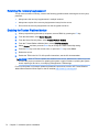
6 Cabling ............................................................................................................................................................ 73
SAS hard drive cabling ....................................................................................................................... 73
Optical drive cabling ........................................................................................................................... 74
FBWC cabling .................................................................................................................................... 75
Chipset SATA cable option ................................................................................................................ 76
PCIe power cable option .................................................................................................................... 79
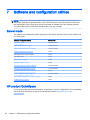
7 Software and configuration utilities ................................................................................................................. 80
Server mode ....................................................................................................................................... 80
HP product QuickSpecs ..................................................................................................................... 80
HP iLO Management Engine .............................................................................................................. 81
HP iLO ............................................................................................................................... 81
Active Health System ........................................................................................ 81
Integrated Management Log ............................................................................. 82
Intelligent Provisioning ....................................................................................................... 82
Erase Utility ....................................................................................................... 83
HP Insight Remote Support software ................................................................................ 83
Scripting Toolkit ................................................................................................................. 84
HP Service Pack for ProLiant ............................................................................................................. 85
HP Smart Update Manager ............................................................................................... 85
HP ROM-Based Setup Utility ............................................................................................................. 86
Using RBSU ....................................................................................................................... 86
Auto-configuration process ................................................................................................ 87
Boot options ....................................................................................................................... 87
Configuring AMP modes .................................................................................................... 87
Re-entering the server serial number and product ID ........................................................ 88
Utilities and features ........................................................................................................................... 88
v
Array Configuration Utility .................................................................................................. 88
HP Smart Storage Administrator ....................................................................................... 89
Option ROM Configuration for Arrays ................................................................................ 89
ROMPaq utility ................................................................................................................... 90
Automatic Server Recovery ............................................................................................... 90
USB support ...................................................................................................................... 91
Redundant ROM support ................................................................................................... 91
Safety and security benefits .............................................................................. 91
Keeping the system current ................................................................................................................ 91
Drivers ............................................................................................................................... 91
Software and firmware ....................................................................................................... 92
Version control ................................................................................................................... 92
HP operating systems and virtualization software support for ProLiant servers ................ 92
HP Technology Service Portfolio ....................................................................................... 92
Change control and proactive notification .......................................................................... 93
8 Troubleshooting .............................................................................................................................................. 94
Troubleshooting resources ................................................................................................................. 94
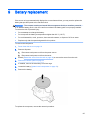
9 Battery replacement ........................................................................................................................................ 95
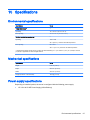
10 Specifications ................................................................................................................................................ 97
Environmental specifications .............................................................................................................. 97
Mechanical specifications ................................................................................................................... 97
Power supply specifications ............................................................................................................... 97
HP 1200 W CS HE Power Supply (94% efficiency) ........................................................... 98
11 Support and other resources ........................................................................................................................ 99
Before you contact HP ....................................................................................................................... 99
HP contact information ....................................................................................................................... 99
Customer Self Repair ....................................................................................................................... 100
12 Acronyms and abbreviations ....................................................................................................................... 101
13 Documentation feedback ............................................................................................................................ 103
Index ................................................................................................................................................................. 104
vi
1
Abstract
This document is for the person who installs, administers, and troubleshoots servers and storage
systems. HP assumes you are qualified in the servicing of computer equipment and trained in
recognizing hazards in products with hazardous energy levels.
While some of the documentation that supports this product contains the HP Proliant and the DL380p
Gen8 Server product names, most of the information in those documents is relevant to this
workstation product. Since this product is supported on VMware and Citrix operating systems only,
information specific to Microsoft Windows and Linux may not apply.
1
2
Component identification
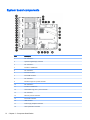
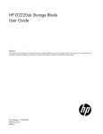
Front panel components
2
Item
Description
1
Video connector
2
SATA optical drive bay
3
Drive bays
4
Systems Insight Display
5
USB connectors (2)
Chapter 2 Component identification
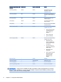
Front panel LEDs and buttons
Item
Description
Status
1
Power On/Standby button and system
power LED
Solid green = System on
Flashing green (1 Hz/cycle per sec) = Performing power on
sequence
Solid amber = System in standby
Off = No power present*
2
Health LED
Solid green = Normal
Flashing amber = System degraded
Flashing red (1 Hz/cycle per sec) = System critical
Fast-flashing red (4 Hz/cycles per sec) = Power fault**
3
NIC status LED
Solid green = Link to network
Flashing green (1 Hz/cycle per sec) = Network active
Off = No network activity
4
UID button/LED
Solid blue = Activated
Flashing blue (1 Hz/cycle per sec) = Remote management or
firmware upgrade in progress
Off = Deactivated
*Facility power is not present, power cord is not attached, no power supplies are installed, power supply failure has occurred,
or the power button cable is disconnected.
**To identify components in a degraded or critical state, see the Systems Insight Display LEDs, check iLO/BIOS logs, and
reference the server troubleshooting guide.
Front panel LEDs and buttons
3
Access the Systems Insight Display
To access a pop-out HP Systems Insight Display:
1.
Press and release the panel.
2.
After the display fully ejects, rotate the display downward to view the LEDs.
Systems Insight Display LEDs
The HP Systems Insight Display LEDs represent the system board layout. The display enables
diagnosis with the access panel installed.
4
Chapter 2 Component identification
Item
Description
Status
1
Power cap
Off = System is in standby, or no cap is set.
Solid green = Power cap applied
2
NIC link/activity
Off = No link to network. If the power is off, view the rear panel
RJ-45 LEDs for status ("Rear panel LEDs and buttons
on page 8).
Flashing green = Network link and activity
Solid green = Network link
3
AMP status
Off = AMP modes disabled
Solid green = AMP mode enabled
Solid amber = Failover
Flashing amber = Invalid configuration
4
Over temp
Off = Normal
Solid amber = High system temperature detected
—
All other LEDs
Off = Normal
Amber = Failure
For more information on the activation of these LEDs, see
"Systems Insight Display LED combinations on page 5."
Systems Insight Display LED combinations
When the health LED on the front panel illuminates either amber or red, the server is experiencing a
health event. Combinations of illuminated Systems Insight Display LEDs, the system power LED, and
the health LED indicate system status.
Systems Insight Display LED
and color
Health LED
System power LED
Status
Processor (amber)
Red
Amber
One or more of the following
conditions may exist:
●
Processor in socket X
has failed.
●
Processor X is not
installed in the socket.
●
Processor X is
unsupported.
●
ROM detects a failed
processor during POST.
Processor (amber)
Amber
Green
Processor in socket X is in a
pre-failure condition.
DIMM (amber)
Red
Green
One or more DIMMs have
failed.
DIMM (amber)
Amber
Green
DIMM in slot X is in a prefailure condition.
Systems Insight Display LED combinations
5
Systems Insight Display LED
and color
Health LED
System power LED
Status
Over temp (amber)
Amber
Green
The Health Driver has
detected a cautionary
temperature level.
Over temp (amber)
Red
Amber
The server has detected a
hardware critical temperature
level.
PCI riser (amber)
Red
Green
The PCI riser cage is not
seated properly.
Fan (amber)
Amber
Green
One fan has failed or has
been removed.
Fan (amber)
Red
Green
Two or more fans have failed
or been removed.
Power supply (amber)
Red
Amber
One or more of the following
conditions may exist:
Power supply (amber)
Amber
Green
●
Only one power supply
is installed and that
power supply is in
standby.
●
Power supply fault
●
System board fault
One or more of the following
conditions may exist:
●
Redundant power
supply is installed and
only one power supply
is functional.
●
AC power cord is not
plugged into redundant
power supply.
●
Redundant power
supply fault
●
Power supply mismatch
at POST or power
supply mismatch
through hot-plug
addition
Power cap (off)
—
Amber
Standby
Power cap (green)
—
Flashing green
Waiting for power
Power cap (green)
—
Green
Power is available.
Power cap (flashing amber)
—
Amber
Power is not available.
IMPORTANT: If more than one DIMM slot LED is illuminated, further troubleshooting is required.
Test each bank of DIMMs by removing all other DIMMs. Isolate the failed DIMM by replacing each
DIMM in a bank with a known working DIMM.
6
Chapter 2 Component identification
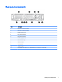
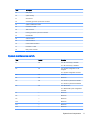
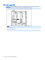
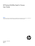
Rear panel components
Item
Description
1
PCIe slots 2–3 (top to bottom)
2
PCIe slots 4–5 (top to bottom)
3
Power supply 1 (PS1)
4
PS1 power connector
5
PS2 power connector
6
Power supply 2 (PS2)
7
USB connectors (4)
8
Video connector
9
iLO connector
10
Serial connector
11
FlexibleLOM ports (Shown: 4 x 1 Gb/Optional: 2 x 10 Gb); port 1 on right side
Rear panel components
7
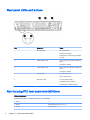
Rear panel LEDs and buttons
Item
Description
Status
1
UID LED/button
Off = Deactivated
Solid blue = Activated
Flashing blue = System being managed
remotely
2
Power supply 2 LED
Off = System is off or power supply has
failed.
Solid green = Normal
3
Power supply 1 LED
Off = System is off or power supply has
failed.
Solid green = Normal
4
NIC link LED
Off = No network link
Green = Network link
5
NIC activity LED
Off = No network activity
Solid green = Link to network
Flashing green = Network activity
Non-hot-plug PCI riser board slot definitions
PCIe slot descriptions
Primary riser connector - connected to processor 1 or southbridge
8
1 - FL/FH
—
2 - HL/FH
PCIe2 or PCIe3 x16 (16, 8, 4, 2, 1)
3 - HL/FH
PCIe2 x8 (4, 2, 1)*
Chapter 2 Component identification
Secondary riser connector - connected to processor 2 (processor 2 must be installed)
4 - FL/FH
PCIe2 or PCIe3 x16 (16, 8, 4, 2, 1)
5 - HL/FH
PCIe2 or PCIe3 x16 (16, 8, 4, 2, 1)
6 - HL/FH
—
FL/FH = full-length, full-height
HL/FH = half-length, full-height
For PCIe slot power capabilities, riser board installation instructions, and riser cage installation instructions, see the user
guide.
*PCIe slot 3 is connected to the southbridge, and runs at Gen2 signaling rate.
Notes:
●
"Primary" denotes the riser cage is installed in the primary riser connector.
●
"Secondary" denotes the riser cage is installed in the secondary riser connector.
●
Slots can generally run at 8 GT/s signaling rate in either PCIe2 or PCIe3 mode, depending on
the capability of the installed processor.
●
Installing the riser cages listed in the table above in either the primary or secondary riser
connectors determines the form factor of the PCI cards supported by those riser cages.
●
FL/FH denotes full-length, full-height. HL/FH denotes half-length, full-height. LP denotes low
profile.
Non-hot-plug PCI riser board slot definitions
9
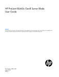
System board components
10
Item
Description
1
Fan connector 6
2
Systems Insight Display connector
3
Fan connector 5
4
Processor 1 DIMM slots
5
Fan connector 4
6
Front I/O connector
7
Front USB connector
8
Fan connector 3
9
First drive cage, box 2 power connector
10
Fan connector 2
11
Processor 2 DIMM slots
12
Second drive cage, box 1 power connector
13
Fan connector 1
14
Discovery services connector
15
Front video connector
16
USB connector
17
Power supply backplane connector
18
SATA optical drive connector
Chapter 2 Component identification
Item
Description
19
NMI jumper
20
System battery
21
SD card slot
22
Secondary (processor 2) PCI riser connector
23
System maintenance switch
24
Processor 2 socket
25
TPM connector
26
Primary (processor 1) PCI riser connector
27
FlexibleLOM
28
SAS connector 1
29
SAS connector 2
30
Cache module connector
31
Processor 1 socket
32
RDX power connector
System maintenance switch
Item
Default
Function
S1
Off
Off = HP iLO security is enabled.
On = HP iLO security is disabled.
S2
Off
Off = System configuration can be
changed.
On = System configuration is locked.
S3
Off
Reserved
S4
Off
Reserved
S5
Off
Off = Power-on password is enabled.
On = Power-on password is disabled.
S6
Off
Off = No function
On = ROM reads system configuration
as invalid.
S7
—
Reserved
S8
—
Reserved
S9
—
Reserved
S10
—
Reserved
S11
—
Reserved
S12
—
Reserved
System board components
11
To access the redundant ROM, set S1, S5, and S6 to on.
When the system maintenance switch position 6 is set to the On position, the system is prepared to
erase all system configuration settings from both CMOS and NVRAM.
CAUTION: Clearing CMOS and/or NVRAM deletes configuration information. Be sure to properly
configure the server or data loss could occur.
NMI functionality
An NMI crash dump enables administrators to create crash dump files when a system is hung and not
responding to traditional debug mechanisms.
Crash dump log analysis is an essential part of diagnosing reliability problems, such as hangs in
operating systems, device drivers, and applications. Many crashes freeze a system, and the only
available action for administrators is to cycle the system power. Resetting the system erases any
information that could support problem analysis, but the NMI feature preserves that information by
performing a memory dump before a hard reset.
To force the OS to invoke the NMI handler and generate a crash dump log, the administrator can use
the iLO Virtual NMI feature.
For more information, see the white paper on the HP website (http://h20000.www2.hp.com/bc/docs/
support/SupportManual/c00797875/c00797875.pdf).
DIMM slot locations
DIMM slots are numbered sequentially (1 through 12) for each processor. The supported AMP modes
use the letter assignments for population guidelines.
12
Chapter 2 Component identification
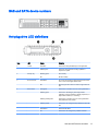
SAS and SATA device numbers
Hot-plug drive LED definitions
Item
LED
Status
Definition
1
Locate
Solid blue
The drive is being identified by a host application.
Flashing blue
The drive carrier firmware is being updated or
requires an update.
Rotating green
Drive activity
Off
No drive activity
Solid white
Do not remove the drive. Removing the drive causes
one or more of the logical drives to fail.
Off
Removing the drive does not cause a logical drive to
fail.
Solid green
The drive is a member of one or more logical drives.
Flashing green
The drive is rebuilding or performing a RAID
migration, strip size migration, capacity expansion, or
logical drive extension, or is erasing.
Flashing amber/green
The drive is a member of one or more logical drives
and predicts the drive will fail.
Flashing amber
The drive is not configured and predicts the drive will
fail.
Solid amber
The drive has failed.
Off
The drive is not configured by a RAID controller.
2
3
4
Activity ring
Do not remove
Drive status
SAS and SATA device numbers
13
PCI riser cage LED
CAUTION: To prevent damage to the server or expansion boards, power down the server and
remove all AC power cords before removing or installing the PCI riser cage.
Status
On = AC power is connected.
Off = AC power is disconnected.
14
Chapter 2 Component identification
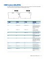
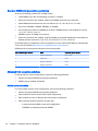
FBWC module LEDs (P420)
The FBWC module has three single-color LEDs (one amber and two green). The LEDs are duplicated
on the reverse side of the cache module to facilitate status viewing.
1 – Amber
2 - Green
3 - Green
Interpretation
Off
Off
Off
The cache module is not
powered.
Off
Flashing 0.5 Hz
Flashing 0.5 Hz
The cache microcontroller is
executing from within its boot
loader and receiving new
flash code from the host
controller.
Off
Flashing 1 Hz
Flashing 1 Hz
The cache module is
powering up, and the
capacitor pack is charging.
Off
Off
Flashing 1 Hz
The cache module is idle,
and the capacitor pack is
charging.
Off
Off
On
The cache module is idle,
and the capacitor pack is
charged.
Off
On
On
The cache module is idle, the
capacitor pack is charged,
and the cache contains data
that has not yet been written
to the drives.
Off
Flashing 1 Hz
Off
A backup is in progress.
Off
On
Off
The current backup is
complete with no errors.
Flashing 1 Hz
Flashing 1 Hz
Off
The current backup failed,
and data has been lost.
Flashing 1 Hz
Flashing 1 Hz
On
A power error occurred
during the previous or
current boot. Data may be
corrupt.
FBWC module LEDs (P420)
15
1 – Amber
2 - Green
3 - Green
Interpretation
Flashing 1 Hz
On
Off
An overtemperature
condition exists.
Flashing 2 Hz
Flashing 2 Hz
Off
The capacitor pack is not
attached.
Flashing 2 Hz
Flashing 2 Hz
On
The capacitor has been
charging for 10 minutes, but
has not reached sufficient
charge to perform a full
backup.
On
On
Off
The current backup is
complete, but power
fluctuations occurred during
the backup.
On
On
On
The cache module
microcontroller has failed.
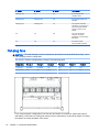
Hot-plug fans
CAUTION: To avoid damage to server components, fan blanks must be installed in fan bays 1 and
2 in a single-processor configuration.
The only two valid fan configurations are listed in the following table.
Configuration
Fan bay 1
Fan bay 2
Fan bay 3
Fan bay 4
Fan bay 5
Fan bay 6
1 processor
Fan blank
Fan blank
Fan
Fan
Fan
Fan
2 processors
Fan
Fan
Fan
Fan
Fan
Fan
For a single-processor configuration, four fans and two blanks are required in specific fan bays for
redundancy. A fan failure or missing fan causes a loss of redundancy. A second fan failure or missing
fan causes an orderly shutdown of the server.
16
Chapter 2 Component identification
Installing more than the required number of fans in a single-processor configuration is not a
supported configuration.
For a dual-processor configuration, six fans are required for redundancy. A fan failure or missing fan
causes a loss of redundancy. A second fan failure or missing fan causes an orderly shutdown of the
server.
The server supports variable fan speeds. The fans operate at minimum speed until a temperature
change requires a fan speed increase to cool the server. The server shuts down during the following
temperature-related scenarios:
●
At POST and in the OS, HP iLO performs an orderly shutdown if a cautionary temperature level
is detected. If the server hardware detects a critical temperature level before an orderly
shutdown occurs, the server performs an immediate shutdown.
●
When the Thermal Shutdown feature is disabled in RBSU, HP iLO does not perform an orderly
shutdown when a cautionary temperature level is detected. Disabling this feature does not
disable the server hardware from performing an immediate shutdown when a critical
temperature level is detected.
CAUTION: A thermal event can damage server components when the Thermal Shutdown
feature is disabled in RBSU.
Hot-plug fans
17
3
Operations
Power up the server
To power up the server, press the Power On/Standby button.
Power down the server
Before powering down the server for any upgrade or maintenance procedures, perform a backup of
critical server data and programs.
IMPORTANT:
system.
When the server is in standby mode, auxiliary power is still being provided to the
To power down the server, use one of the following methods:
●
Press and release the Power On/Standby button.
This method initiates a controlled shutdown of applications and the OS before the server enters
standby mode.
●
Press and hold the Power On/Standby button for more than 4 seconds to force the server to
enter standby mode.
This method forces the server to enter standby mode without properly exiting applications and
the OS. If an application stops responding, you can use this method to force a shutdown.
●
Use a virtual power button selection through HP iLO.
This method initiates a controlled remote shutdown of applications and the OS before the server
enters standby mode.
Before proceeding, verify the server is in standby mode by observing that the system power LED is
amber.
18
Chapter 3 Operations
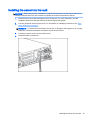
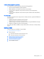
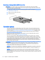
Extend the server from the rack
1.
Pull down the quick release levers on each side of the server.
2.
Extend the server from the rack.
WARNING! To reduce the risk of personal injury or equipment damage, be sure that the rack is
adequately stabilized before extending a component from the rack.
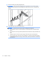
3.
After performing the installation or maintenance procedure, slide the server back into the rack,
and then press the server firmly into the rack to secure it in place.
WARNING! To reduce the risk of personal injury, be careful when pressing the server railrelease latches and sliding the server into the rack. The sliding rails could pinch your fingers.
Extend the server from the rack
19
Remove the access panel
WARNING! To reduce the risk of personal injury from hot surfaces, allow the drives and the internal
system components to cool before touching them.
CAUTION: Do not operate the server for long periods with the access panel open or removed.
Operating the server in this manner results in improper airflow and improper cooling that can lead to
thermal damage.
To remove the component:
1.
Power down the server on page 18.
2.
Extend the server from the rack on page 19.
3.
Open or unlock the locking latch, slide the access panel to the rear of the chassis, and remove
the access panel.
Install the access panel
20
1.
Place the access panel on top of the server with the hood latch open. Allow the panel to extend
past the rear of the server approximately 1.25 cm (0.5 in).
2.
Push down on the hood latch. The access panel slides to a closed position.
3.
Tighten the security screw on the hood latch.
Chapter 3 Operations
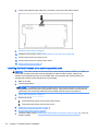
Access the product rear panel
Opening the cable management arm
To access the server rear panel:
1.
Release the cable management arm.
2.
Open the cable management arm. Note that the cable management arm can be right-mounted
or left-mounted.
Access the product rear panel
21
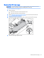
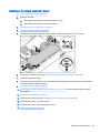
Remove the hot-plug fan cage
To remove the component:
1.
Power down the server on page 18.
2.
Remove all power:
a.
Disconnect each power cord from the power source.
b.
Disconnect each power cord from the server.
3.
Extend (Extend the server from the rack on page 19) or remove the server from the rack.
4.
Remove the access panel on page 20
5.
Remove the air baffle on page 28.
6.
Remove the fan cage.
CAUTION: Do not operate the server for long periods with the access panel open or removed.
Operating the server in this manner results in improper airflow and improper cooling that can lead to
thermal damage.
IMPORTANT: For optimum cooling, install fans in all primary fan locations. For more information,
refer to the fan locations table (Hot-plug fans on page 16).
To replace the component, reverse the removal procedure.
22
Chapter 3 Operations
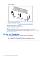
Remove the hot-plug fan
To remove the component:
1.
Extend or remove the server from the rack (Extend the server from the rack on page 19).
2.
Remove the access panel on page 20.
3.
Remove the fan.
CAUTION: Do not operate the server for long periods with the access panel open or removed.
Operating the server in this manner results in improper airflow and improper cooling that can lead to
thermal damage.
IMPORTANT: For optimum cooling, install fans in all primary fan locations. For more information,
refer to the fan locations table (Hot-plug fans on page 16).
To replace the component, reverse the removal procedure.
Remove the hot-plug fan
23
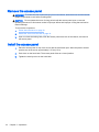
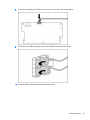
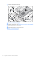
Remove the full-length expansion board
WARNING! To reduce the risk of personal injury, electric shock, or damage to the equipment,
remove the power cord to remove power from the server. The front panel Power On/Standby button
does not completely shut off system power. Portions of the power supply and some internal circuitry
remain active until AC power is removed.
To remove the component:
1.
Power down the server on page 18
2.
Remove all power:
a.
Disconnect each power cord from the power source.
b.
Disconnect each power cord from the server.
3.
Extend (Extend the server from the rack on page 19) or remove the server from the rack.
4.
Remove the access panel on page 20
5.
Disconnect any external cables that are connected to the expansion board.
6.
Disconnect any internal cables that are connected to the expansion board.
7.
Release the full-length expansion board retainer, and then remove the PCIe riser cage.
8.
Remove the full-length expansion board.
To replace the component, reverse the removal procedure.
24
Chapter 3 Operations
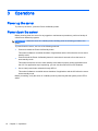
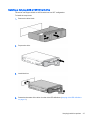
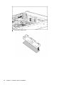
Remove the PCI riser cage
CAUTION: To prevent damage to the server or expansion boards, power down the server and
remove all AC power cords before removing or installing the PCI riser cage.
1.
Power down the server on page 18
2.
Remove all power:
a.
Disconnect each power cord from the power source.
b.
Disconnect each power cord from the server.
3.
Extend (Extend the server from the rack on page 19) or remove the server from the rack.
4.
Remove the access panel on page 20
5.
Release the full-length expansion board retainer, and then remove the PCI riser cage.
6.
Remove the full-length expansion board.
Remove the PCI riser cage
25
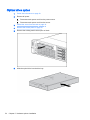
Install the PCI riser cage
WARNING! To reduce the risk of personal injury, electric shock, or damage to the equipment,
remove the power cord to remove power from the server. The front panel Power On/Standby button
does not completely shut off system power. Portions of the power supply and some internal circuitry
remain active until AC power is removed.
1.
Power down the server on page 18
2.
Remove all power:
a.
Disconnect each power cord from the power source.
b.
Disconnect each power cord from the server.
3.
Extend (Extend the server from the rack on page 19) or remove the server from the rack.
4.
Remove the access panel on page 20
5.
Install the PCI riser cage.
6.
Install the access panel on page 20.
7.
Install the server into the rack ("Installing the server into the rack" on page 37).
8.
Connect each power cord to the server.
9.
Connect each power cord to the power source.
10. Power down the server on page 18.
26
Chapter 3 Operations
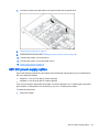
Secure the full-length expansion board retainer
1.
Power down the server on page 18
2.
Remove all power:
a.
Disconnect each power cord from the power source.
b.
Disconnect each power cord from the server.
3.
Extend (Extend the server from the rack on page 19) or remove the server from the rack.
4.
Remove the access panel on page 20
5.
Install a full-length expansion board (Installing a full-length expansion board on page 65).
6.
Install the PCI riser cage on page 26.
7.
Secure the full-length expansion board retainer.
8.
Install the access panel on page 20.
9.
Install the server into the rack (Installing the server into the rack on page 35).
10. Connect each power cord to the server.
11. Connect each power cord to the power source.
12. Power down the server on page 18.
Secure the full-length expansion board retainer
27
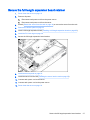
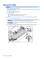
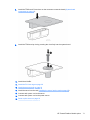
Remove the air baffle
CAUTION: For proper cooling, do not operate the server without the access panel, baffles,
expansion slot covers, or blanks installed. If the server supports hot-plug components, minimize the
amount of time the access panel is open.
To remove the component:
1.
Power down the server on page 18
2.
Remove all power:
a.
Disconnect each power cord from the power source.
b.
Disconnect each power cord from the server.
3.
Extend (Extend the server from the rack on page 19) or remove the server from the rack.
4.
Remove the access panel on page 20
CAUTION: Do not detach the cable that connects the battery pack to the cache module.
Detaching the cable causes any unsaved data in the cache module to be lost.
IMPORTANT: It is necessary to remove the PCI riser cage only if there is a full-length
expansion board installed.
5.
28
Release the full-length expansion board retainer, and then remove the PCI riser cage.
Chapter 3 Operations
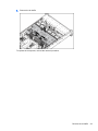
6.
Remove the air baffle.
To replace the component, reverse the removal procedure.
Remove the air baffle
29
4
Setup
Optional installation services
Delivered by experienced, certified engineers, HP Care Pack services help you keep your servers up
and running with support packages tailored specifically for HP ProLiant systems. HP Care Packs let
you integrate both hardware and software support into a single package. A number of service level
options are available to meet your needs.
HP Care Pack Services offer upgraded service levels to expand your standard product warranty with
easy-to-buy, easy-to-use support packages that help you make the most of your server investments.
Some of the Care Pack services are:
●
●
●
Hardware support
◦
Next Business Day Foundation Care
◦
4-Hour 24x7 Foundation Care
Software support
◦
HP ProLiant Essentials (HP SIM and RDP)
◦
VMware
Startup and implementation services for both hardware and software
For more information on HP Care Pack Services, see the HP website (http://www.hp.com/services/
carepack).
30
Chapter 4 Setup
Optimum environment
When installing the server in a rack, select a location that meets the environmental standards
described in this section.
Space and airflow requirements
To allow for servicing and adequate airflow, observe the following space and airflow requirements
when deciding where to install a rack:
●
Leave a minimum clearance of 63.5 cm (25 in) in front of the rack.
●
Leave a minimum clearance of 76.2 cm (30 in) behind the rack.
●
Leave a minimum clearance of 121.9 cm (48 in) from the back of the rack to the back of another
rack or row of racks.
HP servers draw in cool air through the front door and expel warm air through the rear door.
Therefore, the front and rear rack doors must be adequately ventilated to allow ambient room air to
enter the cabinet, and the rear door must be adequately ventilated to allow the warm air to escape
from the cabinet.
CAUTION:
openings.
To prevent improper cooling and damage to the equipment, do not block the ventilation
When vertical space in the rack is not filled by a server or rack component, the gaps between the
components cause changes in airflow through the rack and across the servers. Cover all gaps with
blanking panels to maintain proper airflow.
CAUTION: Always use blanking panels to fill empty vertical spaces in the rack. This arrangement
ensures proper airflow. Using a rack without blanking panels results in improper cooling that can lead
to thermal damage.
The 9000 and 10000 Series Racks provide proper server cooling from flow-through perforations in the
front and rear doors that provide 64 percent open area for ventilation.
CAUTION: When using a Compaq branded 7000 series rack, install the high airflow rack door insert
(PN 327281-B21 for 42U rack, PN 157847-B21 for 22U rack) to provide proper front-to-back airflow
and cooling.
CAUTION: If a third-party rack is used, observe the following additional requirements to ensure
adequate airflow and to prevent damage to the equipment:
●
Front and rear doors—If the 42U rack includes closing front and rear doors, you must allow
5,350 sq cm (830 sq in) of holes evenly distributed from top to bottom to permit adequate airflow
(equivalent to the required 64 percent open area for ventilation).
●
Side—The clearance between the installed rack component and the side panels of the rack must
be a minimum of 7 cm (2.75 in).
IMPORTANT: The HP ProLiant DL380p Gen8 Server cable management arm is not supported on
Compaq branded 7000 series racks.
Optimum environment
31
Temperature requirements
To ensure continued safe and reliable equipment operation, install or position the system in a wellventilated, climate-controlled environment.
The maximum recommended ambient operating temperature (TMRA) for most server products is 35°
C (95° F). The temperature in the room where the rack is located must not exceed 35° C (95° F).
CAUTION:
To reduce the risk of damage to the equipment when installing third-party options:
●
Do not permit optional equipment to impede airflow around the server or to increase the internal
rack temperature beyond the maximum allowable limits.
●
Do not exceed the manufacturer’s TMRA.
Power requirements
Installation of this equipment must comply with local and regional electrical regulations governing the
installation of information technology equipment by licensed electricians. This equipment is designed
to operate in installations covered by NFPA 70, 1999 Edition (National Electric Code) and NFPA-75,
1992 (code for Protection of Electronic Computer/Data Processing Equipment). For electrical power
ratings on options, refer to the product rating label or the user documentation supplied with that
option.
WARNING! To reduce the risk of personal injury, fire, or damage to the equipment, do not overload
the AC supply branch circuit that provides power to the rack. Consult the electrical authority having
jurisdiction over wiring and installation requirements of your facility.
CAUTION: Protect the server from power fluctuations and temporary interruptions with a regulating
uninterruptible power supply. This device protects the hardware from damage caused by power
surges and voltage spikes and keeps the system in operation during a power failure.
When installing more than one server, you may need to use additional power distribution devices to
safely provide power to all devices. Observe the following guidelines:
●
Balance the server power load between available AC supply branch circuits.
●
Do not allow the overall system AC current load to exceed 80% of the branch circuit AC current
rating.
●
Do not use common power outlet strips for this equipment.
●
Provide a separate electrical circuit for the server.
Electrical grounding requirements
The server must be grounded properly for proper operation and safety. In the United States, you must
install the equipment in accordance with NFPA 70, 1999 Edition (National Electric Code), Article 250,
as well as any local and regional building codes. In Canada, you must install the equipment in
accordance with Canadian Standards Association, CSA C22.1, Canadian Electrical Code. In all other
countries, you must install the equipment in accordance with any regional or national electrical wiring
codes, such as the International Electrotechnical Commission (IEC) Code 364, parts 1 through 7.
Furthermore, you must be sure that all power distribution devices used in the installation, such as
branch wiring and receptacles, are listed or certified grounding-type devices.
Because of the high ground-leakage currents associated with multiple servers connected to the same
power source, HP recommends the use of a PDU that is either permanently wired to the building’s
branch circuit or includes a nondetachable cord that is wired to an industrial-style plug. NEMA
32
Chapter 4 Setup
locking-style plugs or those complying with IEC 60309 are considered suitable for this purpose. Using
common power outlet strips for the server is not recommended.
Connecting a DC power cable to a DC power source
WARNING! To reduce the risk of electric shock or energy hazards:
●
This equipment must be installed by trained service personnel, as defined by the NEC and IEC
60950-1, Second Edition, the standard for Safety of Information Technology Equipment.
●
Connect the equipment to a reliably grounded SELV source. An SELV source is a secondary
circuit that is designed so normal and single fault conditions do not cause the voltages to exceed
a safe level (60 V direct current).
●
The branch circuit overcurrent protection must be rated 20A.
WARNING! When installing a DC power supply, the ground wire must be connected before the
positive or negative leads.
WARNING! Remove power from the power supply before performing any installation steps or
maintenance on the power supply.
CAUTION: The server equipment connects the earthed conductor of the DC supply circuit to the
earthing conductor at the equipment. For more information, see the HP 750W Common Slot -48V DC
Input Hot-Plug Power Supply Kit Installation Instructions.
CAUTION: If the DC connection exists between the earthed conductor of the DC supply circuit and
the earthing conductor at the server equipment, the following conditions must be met:
●
This equipment must be connected directly to the DC supply system earthing electrode
conductor or to a bonding jumper from an earthing terminal bar or bus to which the DC supply
system earthing electrode conductor is connected.
●
This equipment should be located in the same immediate area (such as adjacent cabinets) as
any other equipment that has a connection between the earthed conductor of the same DC
supply circuit and the earthing conductor, and also the point of earthing of the DC system. The
DC system should be earthed elsewhere.
●
The DC supply source is to be located within the same premises as the equipment.
●
Switching or disconnecting devices should not be in the earthed circuit conductor between the
DC source and the point of connection of the earthing electrode conductor.
To connect a DC power cable to a DC power source:
1.
Cut the DC power cord ends no shorter than 150 cm (59.06 in).
2.
If the power source requires ring tongues, use a crimping tool to install the ring tongues on the
power cord wires.
IMPORTANT:
The ring tongues must be UL approved and accommodate 12 gauge wires.
IMPORTANT: The minimum nominal thread diameter of a pillar or stud type terminal must be
3.5 mm (0.138 in); the diameter of a screw type terminal must be 4.0 mm (0.157 in).
3.
Stack each same-colored pair of wires and then attach them to the same power source. The
power cord consists of three wires (black, red, and green).
For more information, see the HP 750W Common Slot -48V DC Input Hot-Plug Power Supply
Installation Instructions.
Optimum environment
33
Rack warnings
WARNING! To reduce the risk of personal injury or damage to the equipment, be sure that:
●
The leveling jacks are extended to the floor.
●
The full weight of the rack rests on the leveling jacks.
●
The stabilizing feet are attached to the rack if it is a single-rack installation.
●
The racks are coupled together in multiple-rack installations.
●
Only one component is extended at a time. A rack may become unstable if more than one
component is extended for any reason.
WARNING! To reduce the risk of personal injury or equipment damage when unloading a rack:
●
At least two people are needed to safely unload the rack from the pallet. An empty 42U rack can
weigh as much as 115 kg (253 lb), can stand more than 2.1 m (7 ft) tall, and might become
unstable when being moved on its casters.
●
Never stand in front of the rack when it is rolling down the ramp from the pallet. Always handle
the rack from both sides.
Identifying the contents of the server shipping carton
Unpack the server shipping carton and locate the materials and documentation necessary for
installing the server. All the rack mounting hardware necessary for installing the server into the rack is
included with the rack or the server.
The contents of the server shipping carton include:
●
Server
●
Power cord
●
Hardware documentation, Documentation CD, and software products
●
Rack-mounting hardware
In addition to the supplied items, you might need:
●
Operating system or application software
●
Hardware options
Installing hardware options
Install any hardware options before initializing the server. For options installation information, refer to
the option documentation. For server-specific information, refer to "Hardware options installation
on page 39."
34
Chapter 4 Setup
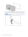
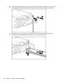
Installing the server into the rack
CAUTION: Always plan the rack installation so that the heaviest item is on the bottom of the rack.
Install the heaviest item first, and continue to populate the rack from the bottom to the top.
1.
Install the server and cable management arm into the rack. For more information, see the
installation instructions that ship with the 2U Quick Deploy Rail System.
2.
Connect peripheral devices to the server. For information on identifying connectors, see "Rear
panel components on page 7."
WARNING! To reduce the risk of electric shock, fire, or damage to the equipment, do not plug
telephone or telecommunications connectors into RJ-45 connectors.
3.
Connect the power cord to the rear of the server.
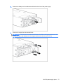
4.
Install the power cord anchors.
Installing the server into the rack
35
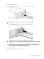
5.
Secure the cables to the cable management arm.
IMPORTANT: When using cable management arm components, be sure to leave enough
slack in each of the cables to prevent damage to the cables when the server is extended from
the rack.
6.
Connect the power cord to the AC power source.
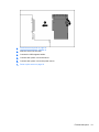
WARNING!
36
To reduce the risk of electric shock or damage to the equipment:
●
Do not disable the power cord grounding plug. The grounding plug is an important safety
feature.
●
Plug the power cord into a grounded (earthed) electrical outlet that is easily accessible at all
times.
●
Unplug the power cord from the power supply to disconnect power to the equipment.
●
Do not route the power cord where it can be walked on or pinched by items placed against
it. Pay particular attention to the plug, electrical outlet, and the point where the cord extends
from the server.
Chapter 4 Setup
Installing the operating system
As with other HP ProLiant servers, this DL380z server does not ship with provisioning media.
Everything needed to manage the installation of system software and firmware is preloaded on the
server.
You have a choice between two operating systems that can be installed on this HP DL380z server:
●
Citrix XenServer
●
VMware vSphere
Citrix XenServer
You may install Citrix XenServer using Intelligent Provisioning. Intelligent Provisioning is a singleserver deployment tool embedded in all HP ProLiant Gen8 servers, and it replaces the SmartStart
CDs and Smart Update Firmware DVD shipped with previous generation HP ProLiant servers. The
CDs and DVD do not ship with HP ProLiant Gen8 servers. To prepare for installing the system
software using Intelligent Provisioning, obtain a supported operating system on a DVD, CD, FTP
server, network, or USB drive. For more information about using Intelligent Provisioning, see the HP
Intelligent Provisioning User Guide (http://www.hp.com/go/intelligentprovisioning/docs).
To install Citrix XenServer on the DL380z with Intelligent Provisioning (local or remote), perform the
following steps:
NOTE:
An Internet connection is required to update the firmware and systems software.
1.
Connect the Ethernet cable between the network connector on the server and a network jack.
2.
Press the Power On/Standby button.
3.
During server POST, press the F10 key.
4.
Complete the initial Preferences and Registration.
5.
At the first Start screen, click the Configure and Install button.
6.
Follow the onscreen prompts to complete the installation.
VMware vSphere
To install VMware vSphere, you may use Insight Control server deployment for an automated
solution. For more information, see the HP Insight Control Server Deployment User Guide in the HP
Insight Software Information Library (http://www.hp.com/go/insightremotesupport/docs).
If HP Insight Remote Support 7.x is installed in the server environment, you need the following
information in order to complete registration:
●
Port number: default port number is 7906
●
IP address (or host name) of the HP Insight Remote Support hosting device
For more information, see the HP Insight Remote Support guides in the HP Insight Remote Support
Information Library (http://www.hp.com/go/insightremotesupport/docs).
Installing the operating system
37
Powering on and selecting boot options
1.
Connect the Ethernet cable.
2.
Press the Power On/Standby button.
3.
During the initial boot:
●
To modify the server configuration ROM default settings, press F9 when prompted from the
start up sequence to enter the RBSU. By default, RBSU runs in the English language.
●
If you do not need to modify the server configuration and are ready to install the system
software, press F10 to access Intelligent Provisioning.
NOTE: If an HP Smart Array controller has been added or is embedded in the system, the
controller defaults to a RAID configuration based on the size and number of hard drives
installed. For more information on modifying the controller default settings, see the
documentation on the Documentation CD.
For more information on automatic configuration, see the HP ROM-Based Setup Utility User Guide on
the Documentation CD or the iLO Management Engine Information Library (http://www.hp.com/go/
ilomgmtengine/docs).
Registering the server
To experience quicker service and more efficient support, register the product at the HP Product
Registration website (http://register.hp.com).
38
Chapter 4 Setup
5
Hardware options installation
Introduction
If more than one option is being installed, read the installation instructions for all the hardware options
and identify similar steps to streamline the installation process.
WARNING! To reduce the risk of personal injury from hot surfaces, allow the drives and the internal
system components to cool before touching them.
CAUTION: To prevent damage to electrical components, properly ground the server before
beginning any installation procedure. Improper grounding can cause electrostatic discharge.
Memory options
IMPORTANT: This server does not support mixing LRDIMMs, RDIMMs, UDIMMs, or HDIMMs.
Attempting to mix any combination of these DIMMs can cause the server to halt during BIOS
initialization.
The memory subsystem in this server can support LRDIMMs, RDIMMs, UDIMMs, or HDIMMs:
●
UDIMMs represent the most basic type of memory module and offer lower latency in one DIMM
per channel configurations and (relatively) low power consumption, but are limited in capacity.
●
RDIMMs offer larger capacities than UDIMMs and include address parity protection.
●
LRDIMMs support higher densities than single- and dual-rank RDIMMs, and higher speeds than
quad-rank RDIMMs. This support enables you to install more high capacity DIMMs, resulting in
higher system capacities and higher bandwidth.
●
HDIMMs provide faster speeds than other DIMMs. 12 DIMMs per processor are required with
HDIMMs.
All types are referred to as DIMMs when the information applies to all types. When specified as
LRDIMM, RDIMM, UDIMM, or HDIMM, the information applies to that type only. All memory installed
in the server must be the same type.
The server supports the following DIMM speeds:
●
Single- and dual-rank PC3-10600 (DDR3-1333) RDIMMs operating at up to 1333 MT/s
●
Single- and dual-rank PC3-12800 (DDR3-1600) RDIMMs operating at up to 1600 MT/s
●
Single- and dual-rank PC3-14900 (DDR3-1866) RDIMMs operating at up to 1866 MT/s
●
Single- and dual-rank PC3-10600 (DDR3-1333) UDIMMs operating at up to 1333 MT/s
●
Quad-rank PC3L-10600 (DDR3-1333) LRDIMMs, operating as dual-rank DIMMs, at up to 1333
MT/s
●
Quad-rank PC3L-14900 (DDR3-1866) LRDIMMs operating as dual-rank DIMMs at up to 1866
MT/s
For the latest memory configuration information, see the product QuickSpecs on the HP Product
Bulletin website (http://www.hp.com/go/productbulletin).
Introduction
39
HP SmartMemory
HP SmartMemory, introduced for Gen8 servers, authenticates and unlocks certain features available
only on HP Qualified memory and verifies whether installed memory has passed HP qualification and
test processes. Qualified memory is performance-tuned for HP ProLiant and BladeSystem servers
and provides future enhanced support through HP Active Health and manageability software.
Certain performance features are unique with HP SmartMemory. HP SmartMemory 1.35V
DDR3-1333 Registered memory is engineered to achieve the same performance level as 1.5V
memory. For example, while the industry supports DDR3-1333 RDIMM at 1.5V, this Gen8 server
supports DDR3-1333 RDIMM up to 3 DIMMs per channel at 1066 MT/s running at 1.35V. This
equates to up to 20% less power at the DIMM level with no performance penalty. In addition, the
industry supports UDIMM at 2 DIMMs per channel at 1066 MT/s. HP SmartMemory supports 2
DIMMs per channel at 1333 MT/s, or 25% greater bandwidth.
Memory subsystem architecture
The memory subsystem in this server is divided into channels. Each processor supports four
channels, and each channel supports three DIMM slots, as shown in the following table.
Channel
1
2
3
4
Population order
Slot number
A
12
E
11
I
10
B
9
F
8
J
7
C
1
G
2
K
3
D
4
H
5
L
6
For the location of the slot numbers, see "DIMM slot locations on page 12."
This multi-channel architecture provides enhanced performance in Advanced ECC mode. This
architecture also enables Lockstep and Online Spare Memory modes.
DIMM slots in this server are identified by number and by letter. Letters identify the population order.
Slot numbers indicate the DIMM slot ID for spare replacement.
40
Chapter 5 Hardware options installation
Single-, dual-, and quad-rank DIMMs
To understand and configure memory protection modes properly, an understanding of single-, dual-,
and quad-rank DIMMs is helpful. Some DIMM configuration requirements are based on these
classifications.
A single-rank DIMM has one set of memory chips that is accessed while writing to or reading from the
memory. A dual-rank DIMM is similar to having two single-rank DIMMs on the same module, with only
one rank accessible at a time. A quad-rank DIMM is, effectively, two dual-rank DIMMs on the same
module. Only one rank is accessible at a time. The server memory control subsystem selects the
proper rank within the DIMM when writing to or reading from the DIMM.
Dual- and quad-rank DIMMs provide the greatest capacity with the existing memory technology. For
example, if current DRAM technology supports 8-GB single-rank DIMMs, a dual-rank DIMM would be
16 GB, and a quad-rank DIMM would be 32 GB.
LRDIMMs are labeled as quad-rank DIMMs; however, they function more like dual-rank DIMMs.
There are four ranks of DRAM on the DIMM, but the LRDIMM buffer creates an abstraction that
allows the DIMM to appear as a dual-rank DIMM to the system. The LRDIMM buffer also isolates the
electrical loading of the DRAM from the system to allow for faster operation. These two changes allow
the system to support up to three LRDIMMs per memory channel, providing for up to 50% greater
memory capacity and higher memory operating speed compared to quad-rank RDIMMs.
DIMM identification
To determine DIMM characteristics, use the label attached to the DIMM and the following illustration
and table.
Item
Description
Definition
1
Size
—
2
Rank
1R = Single-rank
2R = Dual-rank
4R = Quad-rank
3
Data width
x4 = 4-bit
Memory options
41
Item
Description
Definition
x8 = 8-bit
4
Voltage rating
L = Low voltage (1.35v)
U = Ultra low voltage (1.25v)
Blank or omitted = Standard
5
Memory speed
12800 = 1600-MT/s
10600 = 1333-MT/s
8500 = 1066-MT/s
6
DIMM type
R = RDIMM (registered)
E = UDIMM (unbuffered with ECC)
L = LRDIMM (load reduced)
H = HDIMM (HyperCloud)
For the latest supported memory information, see the QuickSpecs on the HP website (http://
h18000.www1.hp.com/products/quickspecs/ProductBulletin.html). At the website, choose the
geographic region, and then locate the product by name or product category.
Memory configurations
To optimize server availability, the server supports the following AMP modes:
●
Advanced ECC—provides up to 4-bit error correction and enhanced performance over Lockstep
mode. This mode is the default option for this server.
●
Online spare memory—provides protection against failing or degraded DIMMs. Certain memory
is reserved as spare, and automatic failover to spare memory occurs when the system detects a
DIMM that is degrading. This allows DIMMs that have a higher probability of receiving an
uncorrectable memory error (which would result in system downtime) to be removed from
operation.
Advanced Memory Protection options are configured in RBSU. If the requested AMP mode is not
supported by the installed DIMM configuration, the server boots in Advanced ECC mode. For more
information, see "HP ROM-Based Setup Utility on page 86."
The server also can operate in independent channel mode or combined channel mode (lockstep).
When running in lockstep mode, you gain reliability in one of two ways:
●
If running with UDIMMs (built with x8 DRAM devices), the system can survive a complete DRAM
failure (SDDC). In independent channel mode, this failure would be an uncorrectable error.
●
If running with RDIMM (built with x4 DRAM devices), the system can survive the complete failure
of two DRAM devices (DDDC). Running in independent mode, the server can only survive the
complete failure of a single DRAM device (SDDC).
Table 5-1 Maximum capacity
42
DIMM type
DIMM rank
One processor
Two processors
RDIMM
Single-rank
96 GB
192 GB
RDIMM
Dual-rank
192 GB
384 GB
Chapter 5 Hardware options installation
Table 5-1 Maximum capacity (continued)
DIMM type
DIMM rank
One processor
Two processors
LRDIMM
Quad-rank
384 GB
768 GB
UDIMM
Single-rank
32 GB
64 GB
UDIMM
Dual-rank
64 GB
128 GB
HDIMM
Dual-rank
192 GB
384 GB
For the latest memory configuration information, see the QuickSpecs on the HP website
(http://www.hp.com).
Advanced ECC memory configuration
Advanced ECC memory is the default memory protection mode for this server. Standard ECC can
correct single-bit memory errors and detect multi-bit memory errors. When multi-bit errors are
detected using Standard ECC, the error is signaled to the server and causes the server to halt.
Advanced ECC protects the server against some multi-bit memory errors. Advanced ECC can correct
both single-bit memory errors and 4-bit memory errors if all failed bits are on the same DRAM device
on the DIMM.
Advanced ECC provides additional protection over Standard ECC because it is possible to correct
certain memory errors that would otherwise be uncorrected and result in a server failure. Using HP
Advanced Memory Error Detection technology, the server provides notification when a DIMM is
degrading and has a higher probability of uncorrectable memory error.
Online Spare memory configuration
Online spare memory provides protection against degraded DIMMs by reducing the likelihood of
uncorrected memory errors. This protection is available without any operating system support.
Online spare memory protection dedicates one rank of each memory channel for use as spare
memory. The remaining ranks are available for OS and application use. If correctable memory errors
occur at a rate higher than a specific threshold on any of the non-spare ranks, the server
automatically copies the memory contents of the degraded rank to the online spare rank. The server
then deactivates the failing rank and automatically switches over to the online spare rank.
Lockstep memory configuration
Lockstep mode provides protection against multi-bit memory errors that occur on the same DRAM
device. Lockstep mode can correct any single DRAM device failure on x4 and x8 DIMM types. The
DIMMs in each channel must have identical HP part numbers.
Memory options
43
General DIMM slot population guidelines
Observe the following guidelines for all AMP modes:
●
Install DIMMs only if the corresponding processor is installed.
●
When two processors are installed, balance the DIMMs across the two processors.
●
White DIMM slots denote the first slot of a channel (Ch 1-A, Ch 2-B, Ch 3-C, Ch 4-D).
●
Do not mix LRDIMMs, UDIMMs, RDIMMs, or HDIMMs.
●
Do not install more than two UDIMMs per channel. UDIMMs should not be installed in slots Ch
1-I, Ch 2-J, Ch 3-K, or Ch 4-L.
●
HDIMMs require 12 DIMMs per processor.
●
When two processors are installed, install the DIMMs in sequential alphabetical order balanced
between the two processors: P1-A, P2-A, P1-B, P2-B, P1-C, P2-C, and so on.
For detailed memory configuration rules and guidelines, use the Online DDR3 Memory Configuration
Tool on the HP website (http://www.hp.com/go/ddr3memory-configurator).
DIMM speeds are supported as indicated in the following table.
Populated slots (per channel)
Rank
Speeds supported (MT/s)
1
Single- or dual-rank
1333, 1600
1
Quad-rank
1333
2
Single- or dual-rank
1333
3
Single- or dual-rank
1066
Advanced ECC population guidelines
For Advanced ECC mode configurations, observe the following guidelines:
●
Observe the general DIMM slot population guidelines.
●
DIMMs may be installed individually.
Online spare population
For Online Spare memory mode configurations, observe the following guidelines:
44
●
Observe the general DIMM slot population guidelines.
●
Each channel must have a valid online spare configuration.
●
Each channel can have a different valid online spare configuration.
●
Each populated channel must have a spare rank:
◦
A single dual-rank DIMM is not a valid configuration.
◦
LRDIMMs are treated as dual-rank DIMMs.
Chapter 5 Hardware options installation
Lockstep Memory population guidelines
For Lockstep memory mode configurations, observe the following guidelines:
●
Observe the general DIMM slot population guidelines.
●
DIMM configuration on all channels of a processor must be identical.
●
In multi-processor configurations, each processor must have a valid Lockstep Memory
configuration.
●
In multi-processor configurations, each processor may have a different valid Lockstep Memory
configuration.
Population order
For memory configurations with a single processor or multiple processors, populate the DIMM slots in
the following order:
●
LRDIMM: Sequentially in alphabetical order (A through L)
●
RDIMM: Sequentially in alphabetical order (A through L)
●
UDIMM: A through H, sequentially in alphabetical order. Do not populate DIMM slots I through L.
●
HDIMM: All 12 DIMMs per processor must be populated.
After installing the DIMMs, use RBSU to configure Advanced ECC, online spare, or lockstep memory
support.
Installing a DIMM
The server supports up to 24 DIMMs. To install a DIMM:
1.
Power down the server on page 18.
2.
Remove all power:
a.
Disconnect each power cord from the power source.
b.
Disconnect each power cord from the server.
3.
Extend the server from the rack on page 19.
4.
Remove the access panel on page 20.
5.
Remove the air baffle on page 28.
6.
Open the DIMM slot latches.
Memory options
45
7.
Install the DIMM.
8.
Install the access panel on page 20.
9.
Install the server into the rack (Installing the server into the rack on page 35).
10. Connect each power cord to the server.
11. Connect each power cord to the power source.
12. Power up the server on page 18.
Use RBSU ("HP ROM-Based Setup Utility" on page 102) to configure the memory mode.
For more information about LEDs and troubleshooting failed DIMMs, see "Systems Insight Display
LED combinations on page 5."
Hot-plug hard drive options
When adding hard drives to the server, observe the following general guidelines:
46
●
The system automatically sets all device numbers.
●
If only one hard drive is used, install it in the bay with the lowest device number.
●
Drives should be the same capacity to provide the greatest storage space efficiency when drives
are grouped together into the same drive array.
Chapter 5 Hardware options installation
Installing a hot-plug SAS or SATA hard drive
The server can support 8 SAS or SATA hard drives in a SFF configuration.
To install the component:
1.
Remove the drive blank.
2.
Prepare the drive.
3.
Install the drive.
4.
Determine the status of the drive from the drive LED definitions (Hot-plug drive LED definitions
on page 13).
Hot-plug hard drive options
47
Removing a hot-plug SAS or SATA hard drive
CAUTION: For proper cooling, do not operate the server without the access panel, baffles,
expansion slot covers, or blanks installed. If the server supports hot-plug components, minimize the
amount of time the access panel is open.
1.
Determine the status of the drive from the hot-plug SAS drive LED combinations (Hot-plug drive
LED definitions on page 13).
2.
Back up all server data on the drive.
3.
Remove the drive.
Controller options
The server ships with an embedded Smart Array P420i controller. For more information about the
controller and its features, see the HP Smart Array Controllers for HP ProLiant Servers User Guide
on the HP website (http://www.hp.com/support/SAC_UG_ProLiantServers_en). To configure arrays,
see the Configuring Arrays on HP Smart Array Controllers Reference Guide on the HP website
(http://www.hp.com/support/CASAC_RG_en).
Upgrade options exist for the integrated array controller. For a list of supported options, see the
QuickSpecs on the HP website (http://www.hp.com/support).
The server supports FBWC. FBWC consists of a cache module and a capacitor pack. The DDR
cache module buffers and stores data being written by the controller. When the system is powered
on, the capacitor pack charges fully in about 5 minutes. In the event of a system power failure, a fully
charged capacitor pack provides power for up to 80 seconds. During that interval, the controller
transfers the cached data from DDR memory to flash memory, where the data remains indefinitely or
until a controller retrieves the data.
CAUTION: The cache module connector does not use the industry-standard DDR3 mini-DIMMs. Do
not use the controller with cache modules designed for other controller models, because the
controller can malfunction and you can lose data. Also, do not transfer this cache module to an
unsupported controller model, because you can lose data.
CAUTION: To prevent a server malfunction or damage to the equipment, do not add or remove the
battery pack while an array capacity expansion, RAID level migration, or stripe size migration is in
progress.
CAUTION: After the server is powered down, wait 15 seconds and then check the amber LED
before unplugging the cable from the cache module. If the amber LED blinks after 15 seconds, do not
remove the cable from the cache module. The cache module is backing up data, and data is lost if the
cable is detached.
48
Chapter 5 Hardware options installation
IMPORTANT: The battery pack might have a low charge when installed. In this case, a POST error
message is displayed when the server is powered up, indicating that the battery pack is temporarily
disabled. No action is necessary on your part. The internal circuitry automatically recharges the
batteries and enables the battery pack. This process might take up to four hours. During this time, the
cache module functions properly, but without the performance advantage of the battery pack.
NOTE: The data protection and the time limit also apply if a power outage occurs. When power is
restored to the system, an initialization process writes the preserved data to the hard drives.
Installing the flash-backed write cache module
CAUTION: The cache module connector does not use the industry-standard DDR3 mini-DIMMs. Do
not use the controller with cache modules designed for other controller models, because the
controller can malfunction and you can lose data. Also, do not transfer this cache module to an
unsupported controller model, because you can lose data.
1.
Back up all data.
2.
Close all applications.
CAUTION: In systems that use external data storage, be sure that the server is the first unit to
be powered down and the last to be powered back up. Taking this precaution ensures that the
system does not erroneously mark the drives as failed when the server is powered up.
3.
Power down the server on page 18.
4.
Remove all power:
a.
Disconnect each power cord from the power source.
b.
Disconnect each power cord from the server.
5.
Extend the server from the rack on page 19.
6.
Remove the access panel on page 20.
7.
Install the cache module.
Controller options
49
8.
Connect the capacitor pack cable to the connector on the top of the cache module.
9.
Install the access panel on page 20.
10. Install the server into the rack (Installing the server into the rack on page 35).
11. Connect each power cord to the server.
12. Connect each power cord to the power source.
13. Power up the server on page 18.
Installing the flash-backed write cache capacitor pack
CAUTION: The cache module connector does not use the industry-standard DDR3 mini-DIMMs. Do
not use the controller with cache modules designed for other controller models, because the
controller can malfunction and you can lose data. Also, do not transfer this cache module to an
unsupported controller model, because you can lose data.
1.
Back up all data.
2.
Close all applications.
CAUTION: In systems that use external data storage, be sure that the server is the first unit to
be powered down and the last to be powered back up. Taking this precaution ensures that the
system does not erroneously mark the drives as failed when the server is powered up.
50
3.
Power down the server on page 18.
4.
Remove all power:
a.
Disconnect each power cord from the power source.
b.
Disconnect each power cord from the server.
5.
Extend the server from the rack on page 19.
6.
Remove the access panel on page 20.
7.
Install the FBWC module (Installing the flash-backed write cache module on page 49), if it is not
already installed.
Chapter 5 Hardware options installation
8.
Connect the capacitor pack cable to the connector on the top of the cache module.
9.
Install one or two FBWC capacitor packs into the FBWC capacitor pack holder.
10. Install the FBWC capacitor pack holder into the server:
Controller options
51
a.
52
Remove the Velcro liner.
Chapter 5 Hardware options installation
b.
Install the FBWC capacitor pack holder into the server.
11. Install the access panel on page 20.
12. Install the server into the rack (Installing the server into the rack on page 35).
13. Connect each power cord to the server.
14. Connect each power cord to the power source.
15. Power up the server on page 18.
Controller options
53
Optical drive option
54
1.
Power down the server on page 18.
2.
Remove all power:
a.
Disconnect each power cord from the power source.
b.
Disconnect each power cord from the server.
3.
Extend the server from the rack on page 19.
4.
Remove the access panel on page 20.
5.
Remove the existing media drive option or blank.
6.
Slide the optical drive into the drive bay.
Chapter 5 Hardware options installation
7.
Connect the power and data cable to the system board and the optical drive.
8.
Install the access panel on page 20.
9.
Install the server into the rack (Installing the server into the rack on page 35).
10. Connect each power cord to the server.
11. Connect each power cord to the power source.
12. Power up the server on page 18.
48V DC power supply option
One of the following optional HP input cables with pre-fastened ring tongues may be purchased from
HP or an authorized reseller:
●
A5S97A—1.3-m (4.27-ft) 48V DC Power Cable Kit
●
A5S98A—2.5-m (8.20-ft) 48V DC Power Cable Kit
If you are not using an optional HP input cable, use an HP-approved 10 or 12 AWG green and yellow
ground cable, no shorter than 150 cm (59.06 in), and 10 or 12 AWG power cables.
To install the component:
1.
Remove the blank.
48V DC power supply option
55
2.
If you are not using an optional HP input cable, with the ground cable disconnected from the 48V
power source, crimp the ring tongues to the power and ground cables coming from the 48V
source.
IMPORTANT: The power supply uses two power ring tongues and one ground ring tongue.
They are not interchangeable.
56
Chapter 5 Hardware options installation
3.
Remove the safety cover from the terminal block on the front of the power supply.
4.
Remove the screws from the terminal block.
IMPORTANT: The minimum nominal thread diameter of a pillar or stud type terminal must be
3.5 mm (0.138 in); the diameter of a screw type terminal must be 4.0 mm (0.157 in).
48V DC power supply option
57
58
5.
Attach the ground (earthed) wire to the ground screw and washer and tighten to 1.47 N m (13 lbin) of torque. The ground wire must be connected before the positive or negative lead wires.
6.
Attach the power ring tongues to the terminal block, following the polarity label below the
terminal block, and then tighten the screws to 1.47 N m (13 lb-in) of torque.
Chapter 5 Hardware options installation
7.
Replace the safety cover.
8.
Insert the power supply into the power supply bay until it clicks into place.
9.
Route the power cord. Use best practices when routing power cords and other cables. A cable
management arm is available to help with routing. To obtain a cable management arm, contact
an HP authorized reseller.
10. Make sure the 48V DC power source is off or the PDU breaker is in the off position, and then
connect the power cord to the 48V DC power source or PDU.
11. Turn on the 48V power source or switch the PDU breaker to the on position to supply 48V to the
power supply.
12. Be sure that the green power supply LED is on.
48V DC power supply option
59
FlexibleLOM option
WARNING! To reduce the risk of personal injury, electric shock, or damage to the equipment,
remove the power cord to remove power from the server. The front panel Power On/Standby button
does not completely shut off system power. Portions of the power supply and some internal circuitry
remain active until AC power is removed.
1.
Power down the server on page 18.
2.
Remove all power:
a.
Disconnect each power cord from the power source.
b.
Disconnect each power cord from the server.
3.
Remove any attached network cables.
4.
Extend the server from the rack on page 19.
5.
Remove the access panel on page 20.
6.
Loosen the thumbscrew.
7.
Remove the existing FlexibleLOM.
To replace the component:
1.
60
Firmly seat the FlexibleLOM in the slot, and then tighten the thumbscrew.
Chapter 5 Hardware options installation
2.
Install the access panel on page 20.
3.
Slide the server into the rack.
4.
Connect the LAN segment cables.
5.
Connect each power cord to the server.
6.
Connect each power cord to the power source.
7.
Power up the server on page 18.
FlexibleLOM option
61
Expansion board options
The server supports PCI Express expansion boards. The server ships with PCIe riser boards and
expansion slots. PCIe expansion boards are supported with optional riser boards.
Removing the expansion slot blanks
WARNING! To reduce the risk of personal injury, electric shock, or damage to the equipment,
remove the power cord to remove power from the server. The front panel Power On/Standby button
does not completely shut off system power. Portions of the power supply and some internal circuitry
remain active until AC power is removed.
CAUTION: For proper cooling, do not operate the server without the access panel, baffles,
expansion slot covers, or blanks installed. If the server supports hot-plug components, minimize the
amount of time the access panel is open.
62
1.
Power down the server on page 18.
2.
Remove all power:
a.
Disconnect each power cord from the power source.
b.
Disconnect each power cord from the server.
3.
Extend (Extend the server from the rack on page 19) or remove the server from the rack.
4.
Remove the access panel on page 20.
5.
Disconnect any external cables that are connected to the expansion board.
6.
Disconnect any internal cables that are connected to the expansion board.
7.
Remove the primary PCIe riser cage (Remove the PCI riser cage on page 25).
8.
Remove the cage cover.
Chapter 5 Hardware options installation
9.
Remove the expansion slot blank.
To replace the component, reverse the removal procedure.
Expansion board options
63
Installing a half-length expansion board
1.
Power down the server on page 18.
2.
Remove all power:
a.
Disconnect each power cord from the power source.
b.
Disconnect each power cord from the server.
3.
Extend the server from the rack on page 19.
4.
Remove the access panel on page 20.
5.
Remove the PCI riser cage on page 25.
6.
Remove the expansion slot blank (Removing the expansion slot blanks on page 62).
7.
Install the expansion board.
8.
Connect any required internal or external cables to the expansion board. See the documentation
that ships with the expansion board.
9.
Install the PCI riser cage on page 26.
10. Install the access panel on page 20.
11. Install the server into the rack (Installing the server into the rack on page 35).
12. Connect each power cord to the server.
13. Connect each power cord to the power source.
14. Power up the server on page 18.
64
Chapter 5 Hardware options installation
Installing a full-length expansion board
1.
Power down the server on page 18.
2.
Remove all power:
a.
Disconnect each power cord from the power source.
b.
Disconnect each power cord from the server.
3.
Extend the server from the rack on page 19.
4.
Remove the access panel on page 20.
5.
Release the full-length expansion board retainer, and then remove the PCI riser cage.
6.
Remove the expansion slot cover (Removing the expansion slot blanks on page 62).
7.
Install the expansion board.
8.
Connect any required internal or external cables to the expansion board. See the documentation
that ships with the expansion board.
9.
Install the PCI riser cage on page 26.
10. Secure the full-length expansion board retainer on page 27 if any full-length expansion boards
are installed.
11. Install the access panel on page 20.
12. Install the server into the rack (Installing the server into the rack on page 35).
13. Connect each power cord to the server.
14. Connect each power cord to the power source.
15. Power up the server on page 18.
Expansion board options
65
Secondary PCI riser cage option
WARNING! To reduce the risk of personal injury, electric shock, or damage to the equipment,
remove the power cord to remove power from the server. The front panel Power On/Standby button
does not completely shut off system power. Portions of the power supply and some internal circuitry
remain active until AC power is removed.
CAUTION: To prevent improper cooling and thermal damage, do not operate the server unless all
PCI slots have either an expansion slot cover or an expansion board installed.
IMPORTANT:
The secondary PCI riser cage option requires both processors.
To install the component:
66
1.
Power down the server on page 18.
2.
Remove all power:
a.
Disconnect each power cord from the power source.
b.
Disconnect each power cord from the server.
3.
Extend the server from the rack on page 19.
4.
Remove the access panel on page 20.
5.
Remove the PCI riser blank.
Chapter 5 Hardware options installation
6.
Remove the secondary PCI riser cage.
7.
Remove the riser cage cover.
8.
Remove the blanks from the secondary PCI riser cage.
9.
Install an expansion board into the PCI riser cage.
10. Install the riser cage cover.
Secondary PCI riser cage option
67
11. Install the secondary PCI riser cage.
12. Install the access panel on page 20.
13. Install the server into the rack (Installing the server into the rack on page 35).
14. Connect each power cord to the server.
15. Connect each power cord to the power source.
16. Power up the server on page 18.
68
Chapter 5 Hardware options installation
2U rack bezel option
The 2U rack bezel helps prevent any unauthorized physical access to the server in the rack
configuration. To access the hard drive cage, you must unlock and open the 2U rack bezel.
To unlock the 2U rack bezel, use the key provided with the kit.
Install the 2U rack bezel into the chassis, and then lock the 2U rack bezel with the key.
HP Trusted Platform Module option
For more information about product features, specifications, options, configurations, and compatibility,
see the product QuickSpecs on the HP Product Bulletin website (http://www.hp.com/go/
productbulletin).
Use these instructions to install and enable a TPM on a supported server. This procedure includes
three sections:
1.
Installing the Trusted Platform Module board.
2.
Retaining the recovery key/password on page 72.
3.
Enabling the Trusted Platform Module on page 72.
Enabling the TPM requires accessing RBSU (HP ROM-Based Setup Utility on page 86). For
more information about RBSU, see the HP website (http://www.hp.com/go/ilomgmtengine/docs).
TPM installation requires the use of drive encryption technology.
CAUTION: Always observe the guidelines in this document. Failure to follow these guidelines can
cause hardware damage or halt data access.
When installing or replacing a TPM, observe the following guidelines:
●
Do not remove an installed TPM. Once installed, the TPM becomes a permanent part of the
system board.
●
When installing or replacing hardware, HP service providers cannot enable the TPM or the
encryption technology. For security reasons, only the customer can enable these features.
2U rack bezel option
69
●
When returning a system board for service replacement, do not remove the TPM from the
system board. When requested, HP Service provides a TPM with the spare system board.
●
Any attempt to remove an installed TPM from the system board breaks or disfigures the TPM
security rivet. Upon locating a broken or disfigured rivet on an installed TPM, administrators
should consider the system compromised and take appropriate measures to ensure the integrity
of the system data.
●
HP is not liable for blocked data access caused by improper TPM use. For operating
instructions, see the encryption technology feature documentation provided by the operating
system.
Installing the Trusted Platform Module board
WARNING! To reduce the risk of personal injury, electric shock, or damage to the equipment,
remove the power cord to remove power from the server. The front panel Power On/Standby button
does not completely shut off system power. Portions of the power supply and some internal circuitry
remain active until AC power is removed.
WARNING! To reduce the risk of personal injury from hot surfaces, allow the drives and the internal
system components to cool before touching them.
1.
Power down the server on page 18
2.
Remove all power:
a.
Disconnect each power cord from the power source.
b.
Disconnect each power cord from the server.
3.
Remove the server from the rack, if necessary.
4.
Place the server on a flat, level work surface.
5.
Remove the access panel on page 20
6.
Remove the PCI riser cage on page 25
7.
Remove the air baffle on page 28
CAUTION: Any attempt to remove an installed TPM from the system board breaks or
disfigures the TPM security rivet. Upon locating a broken or disfigured rivet on an installed TPM,
administrators should consider the system compromised and take appropriate measures to
ensure the integrity of the system data.
70
Chapter 5 Hardware options installation
8.
Install the TPM board. Press down on the connector to seat the board (System board
components on page 10).
9.
Install the TPM security rivet by pressing the rivet firmly into the system board.
10. Install the air baffle.
11. Install the PCI riser cage on page 26
12. Install the access panel on page 20
13. Install the server into the rack (Installing the server into the rack on page 35).
14. Connect each power cord to the server.
15. Connect each power cord to the power source.
16. Power up the server on page 18
HP Trusted Platform Module option
71
Retaining the recovery key/password
To help ensure maximum security, observe the following guidelines when retaining the recovery key/
password:
●
Always store the recovery key/password in multiple locations.
●
Always store copies of the recovery key/password away from the server.
●
Do not save the recovery key/password on the encrypted hard drive.
Enabling the Trusted Platform Module
1.
When prompted during the start-up sequence, access RBSU by pressing the F9 key.
2.
From the Main Menu, select Server Security.
3.
From the Server Security Menu, select Trusted Platform Module.
4.
From the Trusted Platform Module Menu, select TPM Functionality.
5.
Select Enable, and then press the Enter key to modify the TPM Functionality setting.
6.
Press the Esc key to exit the current menu, or press the F10 key to exit RBSU.
7.
Reboot the server.
8.
Enable the TPM in the OS. For OS-specific instructions, see the OS documentation.
CAUTION: When a TPM is installed and enabled on the server, data access is locked if you fail
to follow the proper procedures for updating the system or option firmware, replacing the system
board, replacing a hard drive, or modifying OS application TPM settings.
For more information on firmware updates and hardware procedures, see the HP Trusted Platform
Module Best Practices White Paper on the HP website (http://www.hp.com/support).
72
Chapter 5 Hardware options installation
6
Cabling
SAS hard drive cabling
●
SFF hard drive cabling
●
SFF cabling, with optional drive cage
SAS hard drive cabling
73
●
LFF hard drive cabling
Optical drive cabling
74
Chapter 6 Cabling
FBWC cabling
●
8 drive SFF
●
PCIe option
Depending on the server configuration, you may need to remove the primary PCI riser cage
(Remove the PCI riser cage on page 25) before cabling to a PCIe expansion board.
FBWC cabling
75
Chipset SATA cable option
With the chipset SATA cable option, the chipset SATA controller can be used with a single SATA
hard drive that is installed in one hard drive bay of the SFF or LFF hard drive cage.
●
●
When using the chipset SATA configuration, the following conditions apply:
◦
Only drive bay 5 is enabled. The remaining drive bays are disabled.
◦
The optical bay is disabled because the chipset SATA controller port on the system board
is redirected from the optical bay to the drive cage.
◦
Hard drive status LEDs are not supported.
◦
Hard drive thermal status monitoring is not supported.
◦
Hot-plug operation is not supported.
Because only one drive bay is enabled, all remaining drives can be removed.
For proper thermal cooling, install blanks in all bays that do not have a drive installed. Order a
sufficient number of 6.35-cm (2.5-in) or 8.89-cm (3.5-in) hard drive blank option kits from an HP
authorized reseller. For more information, see the server maintenance and service guide.
●
The standard SATA driver is included with supported operating systems. No additional driver is
required.
1.
Power down the server on page 18.
2.
Remove all power:
a.
Disconnect each power cord from the power source.
b.
Disconnect each power cord from the server.
3.
Extend the server from the rack on page 19.
4.
Remove the access panel on page 20.
WARNING! Eliminate the risk of electric shock by removing all AC power from the system
before installing or replacing any non-hot-plug hardware option. Disconnect all power cords to
completely remove power from the server.
WARNING! To reduce the risk of personal injury from hot surfaces, allow the drives and the
internal system components to cool before touching them.
IMPORTANT: It is necessary to remove the PCI riser cage only if there is a full-length
expansion board installed.
76
Chapter 6 Cabling
5.
Release the full-length expansion board retainer, and then remove the PCI riser cage.
6.
Remove the air baffle on page 28
7.
Remove the fan cage.
8.
Disconnect any SAS cables from the hard drive cage and either the embedded SAS controller or
an optional SAS controller. Do not disconnect the power cable.
Chipset SATA cable option
77
9.
Disconnect the SATA cable from the optical drive and the SATA connector on the system board.
The optical bay is disabled with the chipset SATA cable option.
10. Connect the chipset SATA cable:
a.
Connect the chipset SATA cable connector to the chipset SATA controller port on the
system board. The chipset SATA connector on the SATA cable is narrower than the chipset
SATA controller port header on the system board.
b.
Connect the remaining chipset SATA cable connector to the SATA header on the hard
drive cage.
11. Coil the cables behind the hard drive backplane to minimize airflow impact.
12. Install the fan cage.
13. Install the air baffle (Remove the air baffle on page 28).
14. Install the PCI riser cage on page 26, if removed.
78
Chapter 6 Cabling
15. Secure any full-length PCI expansion boards with the retaining latch on the air baffle (Secure the
full-length expansion board retainer on page 27).
16. Install the access panel on page 20
17. Install the server in the rack (Installing the server into the rack on page 35).
18. Remove any installed hard drives (Removing a hot-plug SAS or SATA hard drive on page 48).
19. Install a SATA hard drive (Installing a hot-plug SAS or SATA hard drive on page 47) in hard
drive bay 5.
20. Install hard drive blanks in any empty hard drive bays.
21. Connect each power cord to the server.
22. Connect each power cord to the power source.
23. Power up the server on page 18
24. Using the HP ROM-Based Setup Utility on page 86, disable the embedded HP Smart Array
P420i Controller, if necessary.
PCIe power cable option
CAUTION: CAUTION: To prevent damage to the server or expansion boards, power down the
server and remove all AC power cords before removing or installing the PCI expansion cage.
Connect the cable that was provided with the PCIe card.
PCIe power cable option
79
7
Software and configuration utilities
NOTE: While some of the documentation that supports this product contains the HP Proliant and
the DL380p Gen8 Server product names, most of the information in those documents is relevant to
this workstation product. Since this product is supported on VMware and Citrix operating systems
only, information specific to Microsoft Windows and Linux may not apply.
Server mode
The software and configuration utilities presented in this section operate in online mode, offline mode,
or in both modes.
Software or configuration utility
Server mode
HP iLO on page 81
Online and Offline
Active Health System on page 81
Online and Offline
Integrated Management Log on page 82
Online and Offline
Intelligent Provisioning on page 82
Offline
HP Insight Remote Support software
Online
HP Insight Online
Online
Erase Utility on page 83
Offline
Scripting Toolkit on page 84
Online
HP Service Pack for ProLiant on page 85
Online and Offline
HP Smart Update Manager on page 85
Online and Offline
HP ROM-Based Setup Utility on page 86
Offline
Array Configuration Utility on page 88
Online and Offline
Option ROM Configuration for Arrays on page 89
Offline
ROMPaq utility on page 90
Offline
HP product QuickSpecs
For more information about product features, specifications, options, configurations, and compatibility,
see the product QuickSpecs on the HP Product Bulletin website (http://www.hp.com/go/
productbulletin).
80
Chapter 7 Software and configuration utilities
HP iLO Management Engine
The HP iLO Management Engine is a set of embedded management features supporting the
complete lifecycle of the server, from initial deployment through ongoing management.
HP iLO
The HP iLO subsystem is a standard component of selected HP ProLiant servers that simplifies initial
server setup, server health monitoring, power and thermal optimization, and remote server
administration. The HP iLO subsystem includes an intelligent microprocessor, secure memory, and a
dedicated network interface. This design makes HP iLO independent of the host server and its
operating system.
HP iLO enables and manages the Active Health System on page 81 and also features Agentless
Management. All key internal subsystems are monitored by HP iLO. SNMP alerts are sent directly by
HP iLO regardless of the host operating system or even if no host operating system is installed.
HP Insight Remote Support software is also available in HP iLO with no operating system software,
drivers, or agents.
Using HP iLO, you can do the following:
●
Access a high-performance and secure Remote Console to the server from anywhere in the
world.
●
Use the shared HP iLO Remote Console to collaborate with up to six server administrators.
●
Remotely mount high-performance Virtual Media devices to the server.
●
Securely and remotely control the power state of the managed server.
●
Have true Agentless Management with SNMP alerts from HP iLO regardless of the state of the
host server.
●
Access Active Health System troubleshooting features through the HP iLO interface.
●
Subscribe to HP Insight Remote Support software without installing any drivers or agents.
For more information about HP iLO features (which may require an iLO Advanced Pack or iLO
Advanced for BladeSystem license), see the HP iLO documentation on the Documentation CD or on
the HP website (http://www.hp.com/go/ilo/docs).
Active Health System
HP Active Health System provides the following features:
●
Combined diagnostics tools/scanners
●
Always on, continuous monitoring for increased stability and shorter downtimes
●
Rich configuration history
●
Health and service alerts
●
Easy export and upload to Service and Support
The HP Active Health System monitors and records changes in the server hardware and system
configuration. The Active Health System assists in diagnosing problems and delivering rapid
resolution when server failures occur.
The Active Health System collects the following types of data:
HP iLO Management Engine
81
●
Server model
●
Serial number
●
Processor number and speed
●
Storage capacity and speed
●
Memory capacity and speed
●
Firmware/BIOS
HP Active Health System does not collect information about Active Health System users' operations,
finances, customers, employees, partners, or data center, such as IP addresses, host names, user
names, and passwords. HP Active Health System does not parse or change operating system data
from third-party error event log activities, such as content created or passed through by the operating
system.
The data that is collected is managed according to the HP Data Privacy policy. For more information
see the HP website (http://www.hp.com/go/privacy).
The Active Health System log, in conjunction with the system monitoring provided by Agentless
Management or SNMP Pass-thru, provides continuous monitoring of hardware and configuration
changes, system status, and service alerts for various server components.
The Agentless Management Service is available in the SPP, which is a disk image (.iso) that you can
download from the HP website (http://www.hp.com/go/spp/download). The Active Health System log
can be downloaded manually from HP iLO or HP Intelligent Provisioning and sent to HP. For more
information, see the HP iLO User Guide or HP Intelligent Provisioning User Guide on the HP website
(http://www.hp.com/go/ilo/docs).
Integrated Management Log
The IML records hundreds of events and stores them in an easy-to-view form. The IML timestamps
each event with 1-minute granularity.
You can view recorded events in the IML in several ways, including the following:
●
From within HP SIM
●
From within operating system-specific IML viewers
●
From within the HP iLO user interface
Intelligent Provisioning
Several packaging changes have taken place with HP ProLiant Gen8 servers: SmartStart CDs and
the Smart Update Firmware DVD will no longer ship with these new servers. Instead, the deployment
capability is embedded in the server as part of HP iLO Management Engine’s Intelligent Provisioning.
Intelligent Provisioning is an essential single-server deployment tool embedded in HP ProLiant Gen8
servers that simplifies HP ProLiant server setup, providing a reliable and consistent way to deploy HP
ProLiant server configurations.
●
82
Intelligent Provisioning assists with the OS installation process by preparing the system for
installing "off-the-shelf" versions of leading operating system software and automatically
integrating optimized HP ProLiant server support software from SPP. SPP is the installation
Chapter 7 Software and configuration utilities
package for operating system-specific bundles of HP ProLiant optimized drivers, utilities,
management agents, and system firmware.
●
Intelligent Provisioning provides maintenance-related tasks through Perform Maintenance
features.
●
Intelligent Provisioning provides installation help for VMware. For specific OS support, see the
HP Intelligent Provisioning Release Notes on the HP website (http://www.hp.com/go/
intelligentprovisioning/docs).
For more information about Intelligent Provisioning software, see the HP website
(http://www.hp.com/go/intelligentprovisioning). For more information about Intelligent Provisioning
drivers, firmware, and SPP, see the HP website (http://www.hp.com/go/spp/download).
Erase Utility
CAUTION: Perform a backup before running the System Erase Utility. The utility sets the system to
its original factory state, deletes the current hardware configuration information, including array setup
and disk partitioning, and erases all connected hard drives completely. Refer to the instructions for
using this utility.
Use the Erase Utility to erase hard drives and Active Health System logs, and to reset RBSU settings.
Run the Erase Utility if you must erase the system for the following reasons:
●
You want to install a new operating system on a server with an existing operating system.
●
You encounter an error when completing the steps of a factory-installed operating system
installation.
To access the Erase Utility, click the Perform Maintenance icon from the Intelligent Provisioning home
screen, and then select Erase.
Run the Erase utility to:
●
Do not erase — does not erase hard drive operations.
●
Reset — erases the master boot record for the hard drives so they are no longer bootable.
●
Secure erase —performs an overwrite pattern erase so no data is recoverable.
After selecting the appropriate option, click Erase Selected. A Confirm Erase window is displayed,
prompting you to confirm or cancel the Erase.
HP Insight Remote Support software
HP strongly recommends that you install HP Insight Remote Support software to complete the
installation or upgrade of your product and to enable enhanced delivery of your HP Warranty, HP
Care Pack Service, or HP contractual support agreement. HP Insight Remote Support supplements
your monitoring continuously to ensure maximum system availability by providing intelligent event
diagnosis, and automatic, secure submission of hardware event notifications to HP, which will initiate
a fast and accurate resolution, based on your product’s service level. Notifications may be sent to
your authorized HP Channel Partner for onsite service, if configured and available in your country.
For more information, see the HP website (http://www.hp.com/go/insightremotesupport). The HP
Insight Remote Support Release Notes detail the prerequisites, supported hardware, and associated
operating systems. The release notes are available on the HP website (http://www.hp.com/go/
insightremotesupport/docs). HP Insight Remote Support is included as part of HP Warranty, HP Care
Pack Service, or HP contractual support agreement.
HP iLO Management Engine
83
Scripting Toolkit
The Scripting Toolkit is a server deployment product that enables you to build an unattended
automated installation for high-volume server deployments. The Scripting Toolkit is designed to
support ProLiant BL, ML, DL, and SL servers. The toolkit includes a modular set of utilities and
important documentation that describes how to apply these tools to build an automated server
deployment process.
The Scripting Toolkit provides a flexible way to create standard server configuration scripts. These
scripts are used to automate many of the manual steps in the server configuration process. This
automated server configuration process cuts time from each deployment, making it possible to scale
rapid, high-volume server deployments.
For more information, and to download the Scripting Toolkit, see the HP website
(http://www.hp.com/go/ProLiantSTK).
84
Chapter 7 Software and configuration utilities
HP Service Pack for ProLiant
SPP is a release set that contains a comprehensive collection of firmware and system software
components, all tested together as a single solution stack for HP ProLiant servers, their options,
BladeSystem enclosures, and limited HP external storage.
SPP has several key features for updating HP ProLiant servers. Using HP SUM as the deployment
tool, SPP can be used in an offline mode where the server is booted to the ISO so that the server can
be updated automatically with no user interaction or updated in interactive mode.
For more information or to download SPP, see the HP website (http://www.hp.com/go/spp).
HP Smart Update Manager
HP SUM is included in many HP products for installing and updating firmware and software on HP
ProLiant servers. HP SUM provides a GUI and a command-line scriptable interface for deployment of
firmware and software for single or one-to-many HP ProLiant servers and network-based targets,
such as iLOs, OAs, and VC Ethernet and Fibre Channel modules.
Key features of HP SUM include:
●
Dependency checking, which ensures appropriate installation order and dependency checking
between components
●
Intelligent deployment of only required updates
●
Simultaneous firmware and software deployment for multiple remote targets in both GUI and CLI
modes
●
Improved deployment performance
●
Local online deployment of HP ProLiant servers and enclosures
●
Remote (one-to-many) online deployment of HP ProLiant servers and enclosures
●
Local offline firmware deployments with HP Support Pack for ProLiant deliverables
●
Remote offline deployment when used with the Scripting Toolkit (HP ProLiant Gen8 and later),
iLO Virtual Media, or PXE booted media
●
GUI or CLI scripts with extensive logging
●
Remote command-line deployment
●
Support for updating firmware on network-based targets such as the OA, iLO through the
Network Management Port, VC Ethernet and Fibre Channel modules, and 3Gb/6Gb SAS BL
Switch interconnects on HP ProLiant servers
For more information about HP SUM and to access the HP Smart Update Manager User Guide, see
the HP website (http://www.hp.com/go/hpsum/documentation).
HP Service Pack for ProLiant
85
HP ROM-Based Setup Utility
RBSU is a configuration utility embedded in HP ProLiant servers that performs a wide range of
configuration activities that can include the following:
●
Configuring system devices and installed options
●
Enabling and disabling system features
●
Displaying system information
●
Selecting the primary boot controller
●
Configuring memory options
●
Language selection
For more information on RBSU, see the HP ROM-Based Setup Utility User Guide on the
Documentation CD or the HP website (http://www.hp.com/support/rbsu).
Using RBSU
To use RBSU, use the following keys:
●
To access RBSU, press the F9 key during power-up when prompted.
●
To navigate the menu system, use the arrow keys.
●
To make selections, press the Enter key.
●
To access Help for a highlighted configuration option, press the F1 key.
IMPORTANT: RBSU automatically saves settings when you press the Enter key. The utility
does not prompt you for confirmation of settings before you exit the utility. To change a selected
setting, you must select a different setting and press the Enter key.
Default configuration settings are applied to the server at one of the following times:
●
Upon the first system power-up
●
After defaults have been restored
Default configuration settings are sufficient for proper typical server operation, but configuration
settings can be modified using RBSU. The system will prompt you for access to RBSU with each
power-up.
86
Chapter 7 Software and configuration utilities
Auto-configuration process
The auto-configuration process automatically runs when you boot the server for the first time. During
the power-up sequence, the system ROM automatically configures the entire system without needing
any intervention. During this process, the ORCA utility, in most cases, automatically configures the
array to a default setting based on the number of drives connected to the server.
NOTE: If the boot drive is not empty or has been written to in the past, ORCA does not
automatically configure the array. You must run ORCA to configure the array settings.
NOTE:
The server may not support all the following examples.
Drives installed
Drives used
RAID level
1
1
RAID 0
2
2
RAID 1
3, 4, 5, or 6
3, 4, 5, or 6
RAID 5
More than 6
0
None
To change any ORCA default settings and override the auto-configuration process, press the F8 key
when prompted.
For more information on RBSU, see the HP ROM-Based Setup Utility User Guide on the
Documentation CD or the HP website (http://www.hp.com/support/rbsu).
Boot options
Near the end of the boot process, the boot options screen is displayed. This screen is visible for
several seconds before the system attempts to boot from a supported boot device. During this time,
you can do the following:
●
Access RBSU by pressing the F9 key.
●
Access Intelligent Provisioning Maintenance Menu by pressing the F10 key.
●
Access the boot menu by pressing the F11 key.
●
Force a PXE Network boot by pressing the F12 key.
Configuring AMP modes
Not all HP ProLiant servers support all AMP modes. RBSU provides menu options only for the modes
supported by the server. Advanced memory protection within RBSU enables the following advanced
memory modes:
●
Advanced ECC Mode—Provides memory protection beyond Standard ECC. All single-bit
failures and some multi-bit failures can be corrected without resulting in system downtime.
●
Online Spare Mode—Provides protection against failing or degraded DIMMs. Certain memory is
set aside as spare, and automatic failover to spare memory occurs when the system detects a
degraded DIMM. DIMMs that are likely to receive a fatal or uncorrectable memory error are
removed from operation automatically, resulting in less system downtime.
For DIMM population requirements, see the server-specific user guide.
HP ROM-Based Setup Utility
87
Re-entering the server serial number and product ID
After you replace the system board, you must re-enter the server serial number and the product ID.
1.
During the server startup sequence, press the F9 key to access RBSU.
2.
Select the Advanced Options menu.
3.
Select Service Options.
4.
Select Serial Number. The following warnings appear:
WARNING! The serial number is loaded into the system during the manufacturing process and
should NOT be modified. This option should only be used by qualified service personnel. This
value should always match the serial number sticker located on the chassis.
The serial number should ONLY be modified by qualified service personnel. This value should
always match the serial number located on the chassis.
5.
Press the Enter key to clear the warning.
6.
Enter the serial number and press the Enter key.
7.
Select Product ID. The following warning appears:
WARNING! The Product ID should ONLY be modified by qualified service personnel. This
value should always match the Product ID on the chassis.
8.
Enter the product ID and press the Enter key.
9.
Press the Esc key to close the menu.
10. Press the Esc key to exit RBSU.
11. Press the F10 key to confirm exiting RBSU. The server automatically reboots.
Utilities and features
Array Configuration Utility
ACU is a utility with the following features:
88
●
Runs as a local application or remote service accessed through the HP System Management
Homepage
●
Supports online array capacity expansion, logical drive extension, assignment of online spares,
and RAID or stripe size migration
●
Suggests the optimum configuration for an unconfigured system
●
For supported controllers, provides access to licensed features, including:
◦
Moving and deleting individual logical volumes
◦
Advanced Capacity Expansion (SATA to SAS and SAS to SATA)
◦
Offline Split Mirror
◦
RAID 6 and RAID 60
◦
RAID 1 (ADM) and RAID 10 (ADM)
Chapter 7 Software and configuration utilities
◦
HP Drive Erase
◦
Video-On-Demand Advanced Controller Settings
●
Provides different operating modes, enabling faster configuration or greater control over the
configuration options
●
Remains available any time that the server is on
●
Displays on-screen tips for individual steps of a configuration procedure
●
Provides context-sensitive searchable help content
●
Provides diagnostic and SmartSSD Wear Gauge functionality on the Diagnostics tab
ACU is now available as an embedded utility, starting with HP ProLiant Gen8 servers. To access
ACU, use one of the following methods:
●
If an optional controller is not installed, press F10 during boot.
●
If an optional controller is installed, when the system recognizes the controller during POST,
press F5.
For optimum performance, the minimum display settings are 1024 × 768 resolution and 16-bit color.
For more information about the controller and its features, see the HP Smart Array Controllers for HP
ProLiant Servers User Guide on the HP website (http://www.hp.com/support/
SAC_UG_ProLiantServers_en). To configure arrays, see the Configuring Arrays on HP Smart Array
Controllers Reference Guide on the HP website (http://www.hp.com/support/CASAC_RG_en).
HP Smart Storage Administrator
HP SSA is a configuration and management tool for HP Smart Array controllers. Starting with HP
ProLiant Gen8 servers, HP SSA replaces ACU with an enhanced GUI and additional configuration
features.
HP SSA exists in three interface formats: the HP SSA GUI, the HP SSA CLI, and HP SSA Scripting.
Although all formats provide support for configuration tasks, some of the advanced tasks are
available in only one format.
Some HP SSA features include the following:
●
Supports online array capacity expansion, logical drive extension, assignment of online spares,
and RAID or stripe size migration
●
Suggests the optimal configuration for an unconfigured system
●
Provides diagnostic and SmartSSD Wear Gauge functionality on the Diagnostics tab
●
For supported controllers, provides access to additional features.
For more information about HP SSA, see the HP website (http://www.hp.com/go/hpssa).
Option ROM Configuration for Arrays
Before installing an operating system, you can use the ORCA utility to create the first logical drive,
assign RAID levels, and establish online spare configurations.
The utility also provides support for the following functions:
●
Reconfiguring one or more logical drives
●
Viewing the current logical drive configuration
Utilities and features
89
●
Deleting a logical drive configuration
●
Setting the controller to be the boot controller
●
Selecting the boot volume
If you do not use the utility, ORCA will default to the standard configuration.
For more information regarding the default configurations that ORCA uses, see the HP ROM-Based
Setup Utility User Guide on the Documentation CD or the HP website (http://www.hp.com/support/
rbsu).
For more information about the controller and its features, see the HP Smart Array Controllers for HP
ProLiant Servers User Guide on the HP website (http://www.hp.com/support/
SAC_UG_ProLiantServers_en). To configure arrays, see the Configuring Arrays on HP Smart Array
Controllers Reference Guide on the HP website (http://www.hp.com/support/CASAC_RG_en).
ROMPaq utility
The ROMPaq utility enables you to upgrade the system firmware (BIOS). To upgrade the firmware,
insert a ROMPaq USB Key into an available USB port and boot the system.
The ROMPaq utility checks the system and provides a choice (if more than one exists) of available
firmware revisions.
For more information, go to the HP website (http://www.hp.com/go/hpsc) and click on Drivers,
Software & Firmware. Then, enter your product name in the Find an HP product field and click Go.
Automatic Server Recovery
ASR is a feature that causes the system to restart when a catastrophic operating system error occurs,
such as a blue screen, ABEND (does not apply to HP ProLiant DL980 Servers), or panic. A system
fail-safe timer, the ASR timer, starts when the System Management driver, also known as the Health
Driver, is loaded. When the operating system is functioning properly, the system periodically resets
the timer. However, when the operating system fails, the timer expires and restarts the server.
ASR increases server availability by restarting the server within a specified time after a system hang.
At the same time, the HP SIM console notifies you by sending a message to a designated pager
number that ASR has restarted the system. You can disable ASR from the System Management
Homepage or through RBSU.
90
Chapter 7 Software and configuration utilities
USB support
HP provides both standard USB 2.0 support and legacy USB 2.0 support. Standard support is
provided by the OS through the appropriate USB device drivers. Before the OS loads, HP provides
support for USB devices through legacy USB support, which is enabled by default in the system
ROM.
Legacy USB support provides USB functionality in environments where USB support is not available
normally. Specifically, HP provides legacy USB functionality for the following:
●
POST
●
RBSU
●
Diagnostics
●
DOS
●
Operating environments which do not provide native USB support
Redundant ROM support
The server enables you to upgrade or configure the ROM safely with redundant ROM support. The
server has a single ROM that acts as two separate ROM images. In the standard implementation,
one side of the ROM contains the current ROM program version, while the other side of the ROM
contains a backup version.
NOTE:
The server ships with the same version programmed on each side of the ROM.
Safety and security benefits
When you flash the system ROM, ROMPaq writes over the backup ROM and saves the current ROM
as a backup, enabling you to switch easily to the alternate ROM version if the new ROM becomes
corrupted for any reason. This feature protects the existing ROM version, even if you experience a
power failure while flashing the ROM.
Keeping the system current
Drivers
IMPORTANT:
Always perform a backup before installing or updating device drivers.
The server includes new hardware that may not have driver support on all OS installation media.
If you are installing an Intelligent Provisioning-supported OS, use Intelligent Provisioning on page 82
and its Configure and Install feature to install the OS and latest supported drivers.
If you do not use Intelligent Provisioning to install an OS, drivers for some of the new hardware are
required. These drivers, as well as other option drivers, ROM images, and value-add software can be
downloaded as part of an SPP.
If you are installing drivers from SPP, be sure that you are using the latest SPP version that your
server supports. To verify that your server is using the latest supported version and for more
information about SPP, see the HP website (http://www.hp.com/go/spp/download).
To locate the drivers for a particular server, go to the HP website (http://www.hp.com/go/hpsc) and
click on Drivers, Software & Firmware. Then, enter your product name in the Find an HP product field
and click Go.
Keeping the system current
91
Software and firmware
Software and firmware should be updated before using the server for the first time, unless any
installed software or components require an older version. For system software and firmware
updates, download the SPP (HP Service Pack for ProLiant on page 85) from the HP website
(http://www.hp.com/go/spp).
Version control
The VCRM and VCA are web-enabled Insight Management Agents tools that HP SIM uses to
schedule software update tasks to the entire enterprise.
●
VCRM manages the repository for SPP. Administrators can view the SPP contents or configure
VCRM to automatically update the repository with internet downloads of the latest software and
firmware from HP.
●
VCA compares installed software versions on the node with updates available in the VCRM
managed repository. Administrators configure VCA to point to a repository managed by VCRM.
For more information about version control tools, see the HP Systems Insight Manager User Guide,
the HP Version Control Agent User Guide, and the HP Version Control Repository User Guide on the
HP website (http://www.hp.com/go/hpsim).
HP operating systems and virtualization software support for ProLiant servers
For information about specific versions of a supported operating system, see the HP website
(http://www.hp.com/go/ossupport).
HP Technology Service Portfolio
HP Technology Services offers a targeted set of consultancy, deployment, and service solutions to
meet the support needs of most business and IT environments.
Foundation Care services—Delivers scalable hardware and software support packages for HP
ProLiant server and industry-standard software. You can choose the type and level of service that is
most suitable for your business needs.
HP Collaborative Support—With a single call, HP addresses initial hardware and software support
needs and helps to quickly identify if a problem is related to hardware or software. If the problem is
related to hardware, HP resolves the problem according to service level commitments. If the reported
incident is related to an HP software product or a supported third-party software product and cannot
be resolved by applying known fixes, HP contacts the third-party vendor and creates a problem
incident on your behalf.
HP Proactive Care—For customers running business critical environments where downtime is not an
option, HP Proactive Care helps to deliver high levels of availability. Key to these service options is
the delivery of proactive service management tools to help you avoid the causes of downtime. If a
problem arises, then HP offers advanced technical response from critical system support specialists
for problem identification and resolution.
HP Support Center—For all service options, the HP Support Center delivers the information, tools,
and experts required to support HP business products.
HP Insight Remote Support—Provides 24x7 secure remote monitoring, diagnosis, and problem
resolution.
For more information, see one of the following websites:
92
Chapter 7 Software and configuration utilities
●
HP ProLiant Server Services website (http://www.hp.com/services/proliant)
●
HP BladeSystem Services website (http://www.hp.com/services/bladesystem)
Change control and proactive notification
HP offers Change Control and Proactive Notification to notify customers 30 to 60 days in advance of
upcoming hardware and software changes on HP commercial products.
For more information, refer to the HP website (http://www.hp.com/go/pcn).
Keeping the system current
93
8
Troubleshooting
Troubleshooting resources
The HP ProLiant Gen8 Troubleshooting Guide, Volume I: Troubleshooting provides procedures for
resolving common problems and comprehensive courses of action for fault isolation and identification,
issue resolution, and software maintenance on ProLiant servers and server blades. To view the
guide, select a language:
●
English (http://www.hp.com/support/ProLiant_TSG_v1_en)
●
French (http://www.hp.com/support/ProLiant_TSG_v1_fr)
●
Spanish (http://www.hp.com/support/ProLiant_TSG_v1_sp)
●
German (http://www.hp.com/support/ProLiant_TSG_v1_gr)
●
Japanese (http://www.hp.com/support/ProLiant_TSG_v1_jp)
●
Simplified Chinese (http://www.hp.com/support/ProLiant_TSG_v1_sc)
The HP ProLiant Gen8 Troubleshooting Guide, Volume II: Error Messages provides a list of error
messages and information to assist with interpreting and resolving error messages on ProLiant
servers and server blades. To view the guide, select a language:
94
●
English (http://www.hp.com/support/ProLiant_EMG_v1_en)
●
French (http://www.hp.com/support/ProLiant_EMG_v1_fr)
●
Spanish (http://www.hp.com/support/ProLiant_EMG_v1_sp)
●
German (http://www.hp.com/support/ProLiant_EMG_v1_gr)
●
Japanese (http://www.hp.com/support/ProLiant_EMG_v1_jp)
●
Simplified Chinese (http://www.hp.com/support/ProLiant_EMG_v1_sc)
Chapter 8 Troubleshooting
9
Battery replacement
If the server no longer automatically displays the correct date and time, you may need to replace the
battery that provides power to the real-time clock.
WARNING! The computer contains an internal lithium manganese dioxide, a vanadium pentoxide,
or an alkaline battery pack. A risk of fire and burns exists if the battery pack is not properly handled.
To reduce the risk of personal injury:
●
Do not attempt to recharge the battery.
●
Do not expose the battery to temperatures higher than 60° C (140° F).
●
Do not disassemble, crush, puncture, short external contacts, or dispose of in fire or water.
●
Replace only with the spare designated for this product.
To remove the component:
1.
Power down the server on page 18
2.
Remove all power.
a.
Disconnect each power cord from the power source.
b.
Disconnect each power cord from the server.
3.
Extend (Extend the server from the rack on page 19) or remove the server from the rack.
4.
Remove the access panel on page 20
5.
If installed, remove the secondary PCIe riser cage.
6.
Locate the battery (System board components on page 10).
7.
Remove the battery.
To replace the component, reverse the removal procedure.
95
For more information about battery replacement or proper disposal, contact an authorized reseller or
an authorized service provider.
96
Chapter 9 Battery replacement
10 Specifications
Environmental specifications
Specification
Value
Temperature range*
—
Operating
10° C to 35° C (50° F to 95° F)
Non-operating
-30° C to 60° C (-22° F to 140° F)
Relative humidity (noncondensing)
—
Operating
10% to 90%
28° C (82.4° F), maximum wet bulb temperature
Non-operating
5% to 95%
38.7° C (101.7° F), maximum wet bulb temperature
* All temperature ratings shown are for sea level. An altitude derating of 1° C per 304.8 m (1.8° F per 1,000 ft) to 3048 m
(10,000 ft) is applicable. No direct sunlight allowed.
Mechanical specifications
Specification
Value
Height
8.73 cm (3.44 in)
Depth
69.85 cm (27.54 in)
Width
44.54 cm (17.54 in)
Weight (minimum—one SFF drive)
18.59 kg (41.0 lb)
Power supply specifications
Depending on installed options, the server is configured with the following power supply:
●
HP 1200 W CS HE Power Supply (94% efficiency)
Environmental specifications
97
HP 1200 W CS HE Power Supply (94% efficiency)
Specification
Value
Input requirements
Rated input voltage
100 to 120 VAC, 200 to 240 VAC
Rated input frequency
50 Hz to 60 Hz
Rated input current
9.1 A at 100 VAC
6.7 A at 200 VAC
Maximum rated input power
897 W at 100V AC input
1321 W at 200V AC input
Btus per hour
3408 at 120V AC input
4433 at 200V to 240V AC input
Power supply output
Rated steady-state power
800 W at 100V AC input
900 W at 120V AC input
1200 W at 200V to 240V AC input
Maximum peak power
800 W at 100V AC input
900 W at 120V AC input
1200 W at 200V to 240V AC input
98
Chapter 10 Specifications
11 Support and other resources
NOTE: While some of the documentation that supports this product contains the HP Proliant and
the DL380p Gen8 Server product names, most of the information in those documents is relevant to
this workstation product. Since this product is supported on VMware and Citrix operating systems
only, information specific to Microsoft Windows and Linux may not apply.
Before you contact HP
Be sure to have the following information available before you call HP:
●
Active Health System log (HP ProLiant Gen8 or later products)
Download and have available an Active Health System log for 3 days before the failure was
detected. For more information, see the HP iLO 4 User Guide or HP Intelligent Provisioning User
Guide on the HP website (http://www.hp.com/go/ilo/docs).
●
Onboard Administrator SHOW ALL report (for HP BladeSystem products only)
For more information on obtaining the Onboard Administrator SHOW ALL report, see the HP
website (http://www.hp.com/go/OAlog).
●
Technical support registration number (if applicable)
●
Product serial number
●
Product model name and number
●
Product identification number
●
Applicable error messages
●
Add-on boards or hardware
●
Third-party hardware or software
●
Operating system type and revision level
HP contact information
For United States and worldwide contact information, see the Contact HP website
(http://www.hp.com/go/assistance).
In the United States:
●
To contact HP by phone, call 1-800-334-5144. For continuous quality improvement, calls may be
recorded or monitored.
●
If you have purchased a Care Pack (service upgrade), see the Support & Drivers website
(http://www8.hp.com/us/en/support-drivers.html). If the problem cannot be resolved at the
website, call 1-800-633-3600. For more information about Care Packs, see the HP website
(http://www.hp.com/go/cpc).
Before you contact HP
99
Customer Self Repair
HP products are designed with many Customer Self Repair (CSR) parts to minimize repair time and
allow for greater flexibility in performing defective parts replacement. If during the diagnosis period HP
(or HP service providers or service partners) identifies that the repair can be accomplished by the use
of a CSR part, HP will ship that part directly to you for replacement. There are two categories of CSR
parts:
●
Mandatory—Parts for which customer self repair is mandatory. If you request HP to replace
these parts, you will be charged for the travel and labor costs of this service.
●
Optional—Parts for which customer self repair is optional. These parts are also designed for
customer self repair. If, however, you require that HP replace them for you, there may or may
not be additional charges, depending on the type of warranty service designated for your
product.
NOTE: Some HP parts are not designed for customer self repair. In order to satisfy the customer
warranty, HP requires that an authorized service provider replace the part. These parts are identified
as "No" in the Illustrated Parts Catalog.
Based on availability and where geography permits, CSR parts will be shipped for next business day
delivery. Same day or four-hour delivery may be offered at an additional charge where geography
permits. If assistance is required, you can call the HP Technical Support Center and a technician will
help you over the telephone. HP specifies in the materials shipped with a replacement CSR part
whether a defective part must be returned to HP. In cases where it is required to return the defective
part to HP, you must ship the defective part back to HP within a defined period of time, normally five
(5) business days. The defective part must be returned with the associated documentation in the
provided shipping material. Failure to return the defective part may result in HP billing you for the
replacement. With a customer self repair, HP will pay all shipping and part return costs and determine
the courier/carrier to be used.
For more information about HP's Customer Self Repair program, contact your local service provider.
For the North American program, refer to the HP website (http://www.hp.com/go/selfrepair).
100 Chapter 11 Support and other resources
12 Acronyms and abbreviations
ABEND
abnormal end
ACU
Array Configuration Utility
AMP
Advanced Memory Protection
ASR
Automatic Server Recovery
CSA
Canadian Standards Association
CSR
Customer Self Repair
DDDC
Double Device Data Correction
DDR
double data rate
FBWC
Flash-Backed Write Cache
HDIMM
HyperCloud DIMM
IEC
International Electrotechnical Commission
iLo
Integrated Lights-Out
IML
Integrated Management Log
ISEE
Instant Support Enterprise Edition
LFF
large form factor
NMI
Non-Maskable Interrupt
NVRAM
non-volatile memory
ORCA
Option ROM Configuration for Arrays
PCIe
Peripheral Component Interconnect Express
POST
Power-On Self Test
PSP
HP ProLiant Support Pack
RBSU
ROM-Based Setup Utility
RDIMM
registered dual in-line memory module
RDP
Rapid Deployment Pack
SAS
Serial Attached SCSI
SATA
serial ATA
SDDC
Single Device Data Correction
SELV
separated extra low voltage
SFF
small form factor
SIM
Systems Insight Manager
SSA
HP Systems Insight Manager
TMRA
recommended ambient operating temperature
101
TPM
Trusted Platform Module
UDIMM
unregistered dual in-line memory module
UID
unit identification
UPS
uninterruptible power system
USB
Universal Serial Bus
VCA
Version Control Agent
102 Chapter 12 Acronyms and abbreviations
13 Documentation feedback
HP is committed to providing documentation that meets your needs. To help us improve the
documentation, send any errors, suggestions, or comments to Documentation Feedback
(mailto:[email protected]). Include the document title and part number, version number, or the
URL when submitting your feedback.
103
Index
A
abbreviations 101
AC power supply 98
access panel 20
acronyms 101
Advanced ECC memory 43, 44,
87
air baffle 28
Array Configuration Utility (ACU)
88
ASR (Automatic Server
Recovery) 90
authorized reseller 99
auto-configuration process 87
Automatic Server Recovery
(ASR) 90
B
battery 95
before you contact HP 99
BIOS upgrade 80, 90
blue screen event 12
boot options 38, 87
buttons 2
C
cable management arm 21, 34
cables 73
cabling 73, 74, 76, 79
capacitor pack 49, 50
Care Pack 30, 83, 92
Change Control 93
chipset data cable 76
components 2
components, identification 2
configuration of system 38, 80
connectors 2
contacting HP 99
controller 48
crash dump analysis 12
CSR (customer self repair) 100
customer self repair (CSR) 99,
100
104 Index
D
DC power supply 33, 55
default settings 43
diagnostic tools 80, 90
DIMM identification 41
DIMM population guidelines 44
DIMM slot locations 12
DIMMs 12, 41
DIMMs, installing 45
DIMMs, single- and dual-rank 41
drive LEDs 13
drivers 91
drives 13
E
electrical grounding
requirements 32
enabling the Trusted Platform
Module 72
environmental requirements 31
environmental specifications 97
Erase Utility 80, 83
error messages 94
expansion board options 62
expansion boards 62
expansion slot blanks 62
expansion slots 64, 65
extending server from rack 19
F
fan cage 22
FBWC cabling 75
FBWC module 15
features 2, 88
firmware 92
firmware update 85, 92
firmware, updating 85, 92
FlexibleLOM 60
front panel buttons 3
front panel components 2
front panel LEDs 3
full-length expansion board
27
FWBC module 49, 50
24,
G
grounding requirements
32
H
hard drive bays 2
hard drive LEDs 13
hard drives, determining status
of 13
hardware options installation 34,
39
health driver 90
health LEDs 3
help resources 99
hot-plug fans 16, 21, 23
hot-plug SAS hard drive options
46
HP Insight Remote Support
software 92
HP Service Pack for ProLiant 80,
85
HP Smart Update Manager
overview 80, 85
HP SmartMemory 40
HP technical support 92, 99
I
ILM (Integrated Management
Log) 80
iLO (Integrated Lights-Out) 80,
81, 82
IML (Integrated Management
Log) 82
Insight Diagnostics 91
installation services 30
installation, server options 34, 39
installing a hot-plug SAS hard
drive 47
installing hardware 39
installing the access panel 20
installing the full-length expansion
board retainer 26
installing the operating system 37
installing the server into the rack
35
installing the Trusted Platform
Module board 70
Integrated Lights-Out (iLO) 81,
82
Integrated Management Log
(IML) 82
Intelligent Provisioning 80, 82
L
LEDs 5, 13
LEDs, front panel 13
LEDs, hard drive 13
LEDs, SAS hard drive 13
LEDs, troubleshooting 14, 94
lockstep memory 43, 45
M
mechanical specifications 97
memory 39, 41, 43
memory configurations 42, 43
memory dump 12
memory subsystem architecture
40
memory, configuration
requirements 42, 45
memory, configuring 42, 43
memory, lockstep 43, 45
memory, online spare 43, 87
N
NMI header
12
O
online spare memory 43, 44, 87
operating system crash 12, 90
operating systems 92
optical drive 2, 54
optical drive cabling 74
optimum environment 31
Option ROM Configuration for
Arrays (ORCA) 80, 89
options installation 34, 39
ORCA (Option ROM Configuration
for Arrays 80, 89
P
PCI expansion slots 8
PCI riser cage 25, 26, 66
phone numbers 99
POST error messages 94
power cabling 79
power distribution unit (PDU) 32
Power On button 18, 38
power requirements 32
power supply 55
power supply LEDs 8
power supply specifications 98
powering down 18
powering up 18
preparation procedures 18
problem diagnosis 94
Q
QuickSpecs
80
R
rack bezel 69
rack installation 30, 34
rack mounting hardware 34
rack warnings 34
RAID configuration 88
RBSU (ROM-Based Setup
Utility) 80, 86, 87
rear panel buttons 8
rear panel components 7
rear panel LEDs 8
rear panel, accessing 21
redundant ROM 91
registering the server 38
removing a hot-plug SAS hard
drive 48
removing the access panel 20
retaining the recovery key/
password 72
ROM redundancy 91
ROMPaq Utility 80
ROMPaq utility 90, 91
S
safety considerations 34, 91
SAS and SATA device numbers
13
scripted installation 84
serial number 88
server features and options 39
server setup 30, 91
Service Packs 85
shipping carton contents 34
Smart Storage Administrator 89
space and airflow requirements
31
specifications 97, 98
specifications, environmental 97
specifications, mechanical 97
specifications, power 98
specifications, server 97
SPP 85
support 99
supported operating systems 92
switches 12
system battery 95
system board components 10
system components 2
system maintenance switch 11,
12
system power LED 3
Systems Insight Display 4, 5
Systems Insight Display LEDs 4,
5
T
technical support 92, 99
telephone numbers 99
temperature requirements 32
TPM (Trusted Platform Module)
69, 72
troubleshooting 94
U
UID LED 12
updating the system ROM 91
USB connector 2
USB support 91
utilities 80, 88
utilities, deployment 80, 84, 86
V
ventilation 31
Version Control 92
Video connector 2
W
warnings 34
website, HP 99
Index 105