1
HP R/T3000 G2 UPS
User Guide
Abstract
This document includes installation, configuration, and operation information for the HP R/T3000 G2 UPS. This document is for the person who
installs and maintains power products. HP assumes you are qualified in the servicing of high-voltage equipment and trained in recognizing hazards
in products with hazardous energy levels.
Part Number: 651176-002
June 2012
Edition: 2
© Copyright 2011, 2012 Hewlett-Packard Development Company, L.P.
The information contained herein is subject to change without notice. The only warranties for HP products and services are set forth in the express
warranty statements accompanying such products and services. Nothing herein should be construed as constituting an additional warranty. HP shall
not be liable for technical or editorial errors or omissions contained herein.
Microsoft®, Windows®, Windows Server®, and Windows Vista® are U.S. registered trademarks of Microsoft Corporation. Bluetooth® is a
trademark owned by its proprietor and used by Hewlett-Packard Company under license.
Contents
Component identification ............................................................................................................... 7
UPS R/T3000 G2 overview ........................................................................................................................ 7
UPS front panel ......................................................................................................................................... 7
UPS front panel controls ............................................................................................................................. 8
UPS front panel LED indicators .................................................................................................................... 8
HP UPS R/T3000 models ........................................................................................................................... 9
R/T3000 NA and R/T3000j JPN rear panel ................................................................................................ 9
R/T3000h NA and R/T3000h JPN rear panel ............................................................................................ 10
R/T3000 INT rear panel .......................................................................................................................... 11
REPO port .............................................................................................................................................. 11
ERM rear panel ....................................................................................................................................... 12
Installation ................................................................................................................................. 13
Precautions ............................................................................................................................................. 13
Preparing to install the hardware ............................................................................................................... 13
Tools and materials ........................................................................................................................ 13
Selecting a site .............................................................................................................................. 14
Readying the equipment ................................................................................................................. 14
Installing the mounting rails ...................................................................................................................... 14
Installing the UPS in a rack ....................................................................................................................... 17
Connecting the battery leads ........................................................................................................... 18
Attaching the UPS front bezel .......................................................................................................... 20
Connecting the host computer ......................................................................................................... 20
Connecting the REPO port .............................................................................................................. 21
Connecting the ground bonding cable ............................................................................................. 23
Connecting the UPS to utility power ................................................................................................. 24
Connecting devices to the UPS ........................................................................................................ 24
Connecting the UPS cord retention clips ........................................................................................... 25
Charging the UPS batteries ............................................................................................................. 25
Starting power to the load .............................................................................................................. 26
Installing the ERM in a rack ...................................................................................................................... 26
Connecting the battery leads ........................................................................................................... 27
Attaching the ERM front bezel ......................................................................................................... 28
Connecting the ERM to the UPS ....................................................................................................... 29
Switching on the ERM circuit breaker ............................................................................................... 30
Charging the ERM batteries ............................................................................................................ 30
Installing the optional UPS Network Module ............................................................................................... 31
Connecting the UPS Network Module .............................................................................................. 32
Installing the UPS as a tower ..................................................................................................................... 32
Connecting the battery leads ........................................................................................................... 33
Rotating the logo badge ................................................................................................................. 33
Attaching the UPS front bezel .......................................................................................................... 34
Attaching the tower conversion stands .............................................................................................. 34
Continuing the installation .............................................................................................................. 34
Installing the ERM as a tower .................................................................................................................... 35
Rotating the logo badge ................................................................................................................. 35
Attaching the ERM front bezel ......................................................................................................... 35
Contents
3
Attaching the tower conversion stands .............................................................................................. 35
Continuing the ERM installation ....................................................................................................... 37
Installing the extension bars (if included) .................................................................................................... 38
Connecting and securing the power cords .................................................................................................. 39
UPS operations ........................................................................................................................... 40
Modes of operation ................................................................................................................................. 40
Standby mode .............................................................................................................................. 40
Operate mode .............................................................................................................................. 40
Configure mode ............................................................................................................................ 41
Battery mode ................................................................................................................................ 41
Auto-Bypass mode ......................................................................................................................... 41
Operating the UPS front panel controls ...................................................................................................... 41
Configuring the UPS ................................................................................................................................ 42
Initiating a self-test ................................................................................................................................... 43
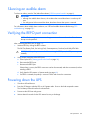
Silencing an audible alarm ....................................................................................................................... 44
Verifying the REPO port connection ........................................................................................................... 44
Powering down the UPS ........................................................................................................................... 44
Maintenance .............................................................................................................................. 45
Removing the UPS front bezel ................................................................................................................... 45
Removing the ERM front bezel................................................................................................................... 45
Replacing the batteries ............................................................................................................................. 45
Important battery safety information ................................................................................................. 46
Battery care and storage guidelines ................................................................................................. 46
Determining when to replace batteries.............................................................................................. 46
Obtaining new batteries ................................................................................................................. 47
UPS battery replacement procedure ................................................................................................. 47
Testing the new battery module ....................................................................................................... 48
Replacing the UPS ................................................................................................................................... 49
Replacing the ERM .................................................................................................................................. 49
Replacing the UPS option card .................................................................................................................. 49
Updating the UPS firmware ...................................................................................................................... 50
Configuring a USB to serial converter............................................................................................... 50
Reassigning the USB COM ports ..................................................................................................... 51
Power management .................................................................................................................... 53
Power Protector software .......................................................................................................................... 53
Troubleshooting .......................................................................................................................... 55
LED troubleshooting ................................................................................................................................. 55
UPS is in Auto-Bypass mode...................................................................................................................... 56
UPS is in Converter Off mode ................................................................................................................... 57
General alarm condition .......................................................................................................................... 57
Bypass is out of range.............................................................................................................................. 58
Battery condition ..................................................................................................................................... 58
UPS is on battery ..................................................................................................................................... 58
Input voltage is out of range ..................................................................................................................... 58
Overtemperature condition ....................................................................................................................... 59
Internal UPS fault condition ....................................................................................................................... 59
REPO condition ....................................................................................................................................... 59
Site wiring condition ................................................................................................................................ 59
Overload condition ................................................................................................................................. 59
Checksum failure error ............................................................................................................................. 60
UPS does not start ................................................................................................................................... 60
Contents
4
Low battery shutdowns ............................................................................................................................. 60
UPS does not provide the expected backup time ......................................................................................... 60
UPS frequently switches between utility and battery power ............................................................................ 60
Specifications ............................................................................................................................. 61
UPS physical specifications ....................................................................................................................... 61
ERM physical specifications ...................................................................................................................... 61
UPS input specifications ........................................................................................................................... 61
UPS output specifications .......................................................................................................................... 61
Power protection specifications ....................................................................................................... 62
Output tolerance specifications ........................................................................................................ 62
Output feature specifications ........................................................................................................... 62
Battery specifications ............................................................................................................................... 62
High-voltage UPS battery runtimes ............................................................................................................. 63
Low-voltage UPS battery runtimes .............................................................................................................. 63
Environmental specifications ..................................................................................................................... 63
REPO port specifications .......................................................................................................................... 63
Spares ....................................................................................................................................... 64
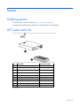
Ordering spares ...................................................................................................................................... 64
UPS spare parts list .................................................................................................................................. 64
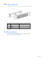
ERM spare parts list ................................................................................................................................. 65
Hardware options ................................................................................................................................... 65
Support and other resources ........................................................................................................ 66
Before you contact HP.............................................................................................................................. 66
HP contact information ............................................................................................................................. 66
Warranty information .................................................................................................................. 67
Limited warranty ..................................................................................................................................... 67
$250,000 Computer Load Protection Guarantee ......................................................................................... 67
Pre-Failure Battery Warranty ..................................................................................................................... 67
Recommended duration of use .................................................................................................................. 68
Regulatory compliance notices ..................................................................................................... 69
Regulatory compliance identification numbers ............................................................................................. 69
Federal Communications Commission notice ............................................................................................... 69
FCC rating label ............................................................................................................................ 69
FCC Notice, Class A Equipment ...................................................................................................... 69
FCC Notice, Class B Equipment ...................................................................................................... 69
Declaration of conformity for products marked with the FCC logo, United States only ....................................... 70
Modifications .......................................................................................................................................... 70
Cables ................................................................................................................................................... 70
Canadian notice (Avis Canadien) .............................................................................................................. 70
European Union regulatory notice ............................................................................................................. 71
Disposal of waste equipment by users in private households in the European Union ......................................... 71
Japanese notice ...................................................................................................................................... 72
BSMI notice ............................................................................................................................................ 72
Korean notice ......................................................................................................................................... 72
Chinese notice ........................................................................................................................................ 73
Battery replacement notice........................................................................................................................ 73
Taiwan battery recycling notice ................................................................................................................. 73
Power cord statement for Japan................................................................................................................. 74
Electrostatic discharge ................................................................................................................. 75
Contents
5
Preventing electrostatic discharge .............................................................................................................. 75
Grounding methods to prevent electrostatic discharge .................................................................................. 75
Acronyms and abbreviations ........................................................................................................ 76
Documentation feedback ............................................................................................................. 77
Index ......................................................................................................................................... 78
Contents
6
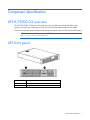
Component identification
UPS R/T3000 G2 overview
The HP UPS R/T3000 G2 features a 2U rack-mount with convertible tower design and offers power
protection for loads up to a maximum of 3300 VA/3000 W (these numbers might vary by model).
To benefit from the latest product enhancements, update to the latest versions of UPS firmware and software.
NOTE: To download the latest versions of UPS firmware and software, see the HP website
(http://www.hp.com/go/rackandpower).
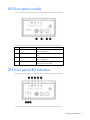
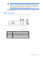
UPS front panel
Item
Description
1
Battery compartment
2
Front panel display
Component identification 7
UPS front panel controls
Item
Description
Function
1
Test/Alarm Reset button
Silences UPS alarms ("Silencing an audible
alarm" on page 44)
2
Off button
Places the UPS in Standby mode (on page
40)
3
On button
Powers up the UPS ("Starting power to the
load" on page 26)
4
Battery Start button
Starts the UPS on battery power when
pressed with the On button
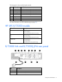
UPS front panel LED indicators
Component identification 8
The front panel is shown with the bezel removed.
Item
LED description
Load level
1
Self Test
On—The load level is greater than 10%.
2
Battery Fault
On—The load level is greater than 25%.
3
Site Wiring Fault
On—The load level is greater than 50%.
4
Overtemperature
On—The load level is greater than 75%.
5
Overload
On—The load level is greater than 100%.
6
On Bypass
7
On Battery
8
Utility
For more information, see "LED troubleshooting (on page 55)" .
HP UPS R/T3000 models
UPS model
Description
R/T3000 NA and R/T3000j JPN •
•
•
Domestic/Japanese
Low-voltage
Nondetachable NEMA L5-30 plug
R/T3000h NA and R/T3000h
JPN
•
•
•
Domestic
High-voltage
Nondetachable NEMA L6-20 plug
R/T3000 INT
•
•
•
International
High-voltage
Detachable country-specific plug
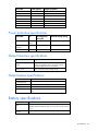
R/T3000 NA and R/T3000j JPN rear panel
Item
Description
1
UPS option card
2
USB communications port
3
Serial communications port
Component identification 9
Item
Description
4
Load segment circuit breaker
5
Load segment 1 (two NEMA 5-20R T-Slot receptacles)
6
Load segment circuit breaker
7
Load segment 2 (two NEMA 5-20R T-Slot receptacles)
8
PDU output (NEMA L5-30R) receptacle (load segment 1)
9
Cord retention clip attachment location
10
Cord retention clip attachment location
11
Ground bonding screw
12
Power cord with L5-30 plug
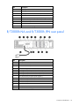
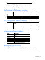
R/T3000h NA and R/T3000h JPN rear panel
Item
Description
1
UPS option card
2
USB communications port
3
Serial communications port
4
Ground bonding screw
5
Load segment 1 and 2 (one IEC-320-C19 receptacle)
6
Load segment 1 (three IEC-320-C13 receptacles)
7
Load segment 2 (three IEC-320-C13 receptacles)
8
PDU output (L6-20) receptacle (load segment 1)
9
Cord retention clip attachment location
10
Cord retention clip attachment location
11
Cord retention clip attachment location
12
Ground bonding screw
13
REPO port
14
Power cord with L6-20 plug
Component identification 10
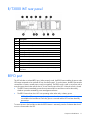
R/T3000 INT rear panel
Item
Description
1
UPS option card
2
USB communications port
3
Serial communications port
4
Ground bonding screw
5
Load segment 1 and 2 (one IEC-320-C19 receptacle)
6
Load segment 1 (three IEC-320-C13 receptacles)
7
Load segment 2 (three IEC-320-C13 receptacles)
8
Cord retention clip attachment location
9
Cord retention clip attachment location
10
Cord retention clip attachment location
11
Ground bonding screw
12
REPO port
13
Input power receptacle (IEC-320-C19) for country-specific plug
attachment
REPO port
The UPS includes an isolated REPO port. When properly wired, the REPO feature enables the power at the
UPS output receptacles to be switched off from a remote location. To use this feature, the REPO port must be
connected to a remote, normally-open switch (not supplied). The REPO switch is used in conjunction with a
main disconnect device that removes the AC source from the input of the UPS. When the switch is closed:
•
The REPO feature immediately powers down protected devices and does not utilize the orderly
shutdown procedure initiated by power management software.
•
The REPO feature shuts down UPS units operating under either utility or battery power.
NOTE: If the UPS was operating on battery power when the remote switch was closed, no power
is available to the load devices until utility power is restored and the UPS has been manually
powered up.
To restore power to the load devices after the REPO feature is activated, press the On button after the AC
source is reconnected to the UPS.
Component identification 11
IMPORTANT: Pressing and holding the On button without utility present normally initiates a
battery start and the UPS assumes the load. However, if the On button is pressed and a REPO is
detected, battery start is inhibited and the UPS is not able to assume the load. The electronics
module fan spins, and the Self Test, Battery Fault, Site Wiring Fault, and Overtemperature LEDs
and an audible alarm are active as long as the On button is held.
To power down the entire network in the event of an emergency, the REPO ports of multiple UPS units can be
connected to a single switch.
ERM rear panel
Item
Description
1
Circuit breaker
2
ERM output connector cable (to the UPS)
3
ERM input connector (from another ERM)
Component identification 12
Installation
Precautions
Save these instructions. This document contains important safety instructions that should be followed during
installation, operation, and maintenance of the UPS and batteries.
WARNING: A risk of personal injury from electric shock and hazardous energy levels exists. The
installation of options and routine maintenance and service of this product must be performed by
individuals who are knowledgeable about the procedures, precautions, and hazards associated
with AC power products.
37 kg
82 lb
45 kg
100 lb
This symbol indicates that the UPS exceeds the recommended weight for one individual
to handle safely.
WARNING: To reduce the risk of personal injury or damage to the equipment, observe
local occupational health and safety requirements and guidelines for manual material
handling.
This symbol indicates that the ERM exceeds the recommended weight for one individual
to handle safely.
WARNING: To reduce the risk of personal injury or damage to the equipment, observe
local occupational health and safety requirements and guidelines for manual material
handling.
WARNING: To prevent personal injury from earth conductor leakage current:
• Do not operate the UPS while disconnected from the utility power source.
• Disconnect load devices before disconnecting the UPS from the utility power source.
Preparing to install the hardware
Before installing the hardware:
1.
Be sure the necessary tools and materials (on page 13) are available.
2.
Select an installation site ("Selecting a site" on page 14).
3.
Prepare the equipment ("Readying the equipment" on page 14) for installation in the rack.
Tools and materials
The following tools are required for installation:
•
Phillips screwdriver
•
10-mm hex-nut driver
The following items are supplied with the rack:
•
Screws
Installation 13
•
Hex nuts
•
Cage nuts
•
Cage nut-fitting tool
Selecting a site
WARNING: To prevent fire or electric shock, install the unit in a temperature- and
humidity-controlled indoor environment, free of conductive contaminants.
When selecting a site, consider the following factors:
•
Elevated operating ambient temperature—If the equipment is installed in a closed or multi-unit rack
assembly, the operating ambient temperature of the rack environment might be greater than room
ambient temperature. Install the equipment in an environment compatible with the operating
temperature ("Environmental specifications" on page 63).
•
Reduced air flow—In the rack, the rate of air flow required for safe operation of the equipment must not
be compromised.
•
Circuit overloading—Consideration should be given to the connection of the equipment to the supply
circuit and the effect that overloading of the circuits might have on overcurrent protection and supply
wiring. Appropriate consideration of equipment nameplate ratings should be used when addressing
this concern.
•
Reliable earthing—Reliable earthing of rack-mounted equipment should be maintained. Particular
attention should be given to supply connections other than direct connections to the branch circuit, such
as the use of power strips.
•
Electrical requirements—All models require a dedicated (unshared) branch circuit, suitably rated for the
specific UPS as stated in "Input specifications ("UPS input specifications" on page 61)" .
Readying the equipment
1.
Check the battery recharge date specified on the label that is affixed to the shipping carton.
IMPORTANT: Do not use the battery if the recharge date has passed. If the date on the battery
recharge date label has passed without the battery being recharged, contact an HP authorized
service representative for directions.
2.
Transport the packaged unit to its installation location.
3.
Unpack the equipment near the rack where the unit will be assembled.
CAUTION: Always plan the rack installation so that the heaviest item is on the bottom of the rack.
Install the heaviest item first, and continue to populate the rack from the bottom to the top.
Installing the mounting rails
Installation 14
WARNING: To reduce the risk of personal injury or damage to the equipment, be sure that:
•
•
•
•
•
The leveling feet are extended to the floor.
The full weight of the rack rests on the leveling feet.
The stabilizing feet are attached to the rack if it is a single-rack installation.
The racks are coupled together in multiple-rack installations.
Only one component is extended at a time. A rack may become unstable if more than one
component is extended for any reason.
If preparing the rails for integrated shipping, follow the same instructions in "Installing the UPS in a rack (on
page 17)" or "Installing the UPS as a tower (on page 32)."
Mounting hardware for square- and round-holed racks is included in the UPS kit.
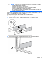
To install the mounting rails:
1.
Loosen the wing nuts or hex nuts, and then extend the brackets to the appropriate length.
2.
Insert screws through the rack into the mounting rail and the front of each mounting bracket.
Installation 15
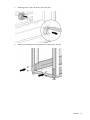
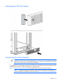
3.
Install cage nuts or clip nuts into the rear of the rack.
4.
Insert screws through the mounting rail into the cage nuts or clip nuts.
Installation 16
5.
Tighten the wing nuts or hex nuts.
6.
Install the rear stabilization bracket using wing nuts. Wait until the unit is installed and the brackets are
adjusted before tightening the nuts.
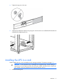
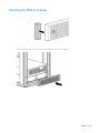
Installing the UPS in a rack
Before installing the unit, review and adhere to all warnings provided in "Precautions (on page 13)."
WARNING: A risk of personal injury or damage to the equipment exists. Uneven loading of
equipment in the rack might cause the rack to become unstable. Install the heavier components
first, and then continue to populate the rack from the bottom to the top.
1.
Install the mounting rails.
Installation 17
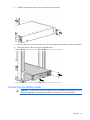
2.
Install the mounting ears on the chassis using the screws provided.
3.
With one person on each side, lift the chassis to rail level and slide the chassis on the mounting rails.
4.
Attach the chassis to the rack using the supplied screws.
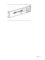
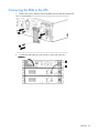
Connecting the battery leads
WARNING: To prevent personal injury from electric shock or damage to the equipment, remove
the battery lead labels, and verify that the ERM circuit breakers are in the Off position.
Installation 18
Installation 19
Attaching the UPS front bezel
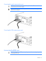
Connecting the host computer
CAUTION: Only one communications port can be connected to the host computer. Connecting
more than one will result in unexpected UPS behavior. If an option card is installed, the serial and
USB communications ports are automatically disabled.
Connect the UPS to a host computer using either the USB cable or the DB9 serial cable included with the UPS.
Install HP Power Protector on the host computer. See the HP website
(http://www.hp.com/go/rackandpower) to download the latest version of HP Power Protector.
NOTE: To install and configure the software, see the software user guide. The software user
guide is available for download from the HP website (http://www.hp.com/go/rackandpower).
Installation 20
Connecting the serial communications port
CAUTION: Use only the computer interface cable supplied with the UPS to connect the
communications port to the host computer.
IMPORTANT: Power protector software requires the communications port to be appropriately
cabled to the host computer.
Connecting the USB communications port
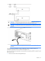
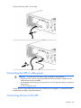
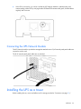
Connecting the REPO port
WARNING: The pins on the REPO port are polarity sensitive. Be sure to verify polarity while
connecting the REPO port.
Installation 21
WARNING: To meet the requirements stated in NEC (NFPA 70) Articles 645-10 and 645-11, a
UPS installed in a computer equipment room must be connected to a REPO circuit.
IMPORTANT: The remote switch must be in the Off (open) position to enable power to the output
receptacles.
NOTE: Wire the connector block using stranded, nonshielded wire (AWG #22 - #18, or
equivalent).
Separate wire pairs are attached to a single, normally-open contact in a parallel connection. HP
recommends using different colors for the positive and negative wires.
If a connector becomes disconnected and is reconnected with reversed polarity, a REPO is initiated. To avoid
REPO port disconnect:
•
Minimize wire strain while connecting the REPO port.
Installation 22
•
Avoid allowing the wires to hang in the rear of the UPS.
•
Use tie wraps and tie wrap blocks to secure the wires tightly to the rack and the rear of the UPS.
For more information about the REPO port, see "REPO port (on page 11)".
For information about verifying the REPO connection, see "Verifying the REPO port connection (on page
44)".
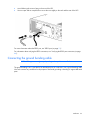
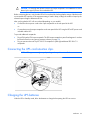
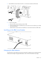
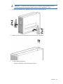
Connecting the ground bonding cable
NOTE: UPS appearance might vary depending on the specific unit installed.
The ground bonding screw is provided as an attachment point for conductors. Use a ground bonding cable
if the rack contains any conductors for the purpose of functional grounding or bonding of ungrounded metal
parts.
Installation 23
The ground bonding cable is not included.
Connecting the UPS to utility power
WARNING: To prevent injury from electric shock or damage to the equipment:
• Plug the input line cord into a grounded (earthed) electrical outlet that is installed near the
equipment and is easily accessible.
• Do not disable the grounding plug on the input line cord. The grounding plug is an important
safety feature.
• Do not use extension cords.
Connect the UPS to a grounded utility power outlet. When the UPS is plugged in, it automatically enters
Standby mode and begins charging the batteries.
Connecting devices to the UPS
Installation 24
CAUTION: Do not plug laser printers into the UPS output receptacles. The instantaneous current
drawn by this type of printer can overload the UPS.
Before connecting devices, verify that the UPS will not overload by checking that the ratings of the devices do
not exceed the UPS capacity. If the equipment rating is listed in amps, multiply the number of amps by the
selected output voltage to determine the VA.
After verifying that the UPS will not overload (depending on your model):
•
Connect the device power cords to the output receptacles on the rear panel of the UPS.
-or-
•
Connect devices to the output receptacles on the rear panel of the UPS using the IEC-to-IEC power cords
included with the UPS.
To provide additional receptacles:
•
Plug a PDU into the PDU output receptacle. The PDU output receptacle is part of load segment 1 and can
be turned off and on using power protector software (on page 53).
•
Plug an extension bar into any IEC-320-C19 receptacle to yield eight additional IEC-320-C13
receptacles.
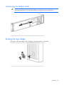
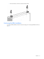
Connecting the UPS cord retention clips
NOTE: UPS appearance might vary depending on the specific unit installed.
Charging the UPS batteries
With the UPS in Standby mode, allow the batteries to charge before putting the UPS into service.
Installation 25
IMPORTANT: Charge the batteries for at least 24 hours before supplying backup power to
devices. The batteries charge to:
• 80 percent of their capacity within 3 hours
• 100 percent of their capacity within 48 hours
Starting power to the load
Start power to the load by placing the UPS in Operate mode (on page 40).
IMPORTANT: AC power must be available the first time the UPS is started.
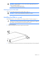
Installing the ERM in a rack
Before installing the unit, review and adhere to all warnings provided in "Precautions (on page 13)."
WARNING: A risk of personal injury or damage to the equipment exists. Uneven loading of
equipment in the rack might cause the rack to become unstable. Install the heavier components
first, and then continue to populate the rack from the bottom to the top.
1.
Install the mounting rails.
2.
Install the mounting ears on the chassis using the screws provided.
3.
With one person on each side, lift the chassis to rail level and slide the chassis on the mounting rails.
Installation 26
4.
Attach the chassis to the rack using the supplied screws.
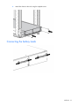
Connecting the battery leads
Installation 27
Attaching the ERM front bezel
Installation 28
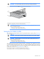
Connecting the ERM to the UPS
1.
Remove the screws, and then remove the ERM connector bracket from the UPS.
2.
Connect the ERM cable (2) in the socket (1) at the rear of the UPS.
Installation 29
3.
Attach the ERM connector bracket to the UPS as a cord retention bracket for the ERM cable.
4.
To install a second ERM:
a. Remove the ERM connector bracket from the first ERM.
b. Connect the cable from the second ERM into the socket at the rear of the first ERM. Up to two ERM
units can be connected.
c.
Attach the ERM connector bracket to the first ERM as a cord retention bracket for the ERM cable.
Switching on the ERM circuit breaker
Charging the ERM batteries
Connect the UPS to a grounded utility power outlet. When the UPS is plugged in, the unit automatically enters
Standby mode and begins charging the ERM batteries. Allow 48 hours for the ERM to fully charge.
Installation 30
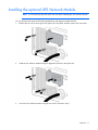
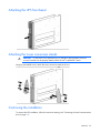
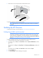
Installing the optional UPS Network Module
NOTE: It is not necessary to power down the UPS before installing the UPS Network Module.
You can purchase the optional UPS Network Module by ordering part number AF465A.
1.
Remove the two screws securing the UPS option slot cover plate, and then remove the cover plate.
2.
Install the UPS Network Module along the alignment channels in the option slot.
3.
Secure the UPS Network Module using the two screws removed in step 1.
Installation 31
4.
If the UPS is powered up, you can be sure that the UPS Network Module is seated properly and
communicating with the UPS by verifying that the UPS Data LED illuminates solid green, and then flashes
regularly after 2 minutes.
Connecting the UPS Network Module
The UPS Network Module is provided to manage the attached servers. RJ 45 network patch panel cables are
required to use this card.
The RJ 45 network patch panel cables are not included.
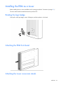
Installing the UPS as a tower
Before installing the unit, review and adhere to all warnings provided in "Precautions (on page 13)."
Installation 32
Connecting the battery leads
WARNING: To prevent personal injury from electric shock or damage to the equipment, remove
the battery lead labels, and verify that the ERM circuit breakers are in the Off position.
Rotating the logo badge
Gently pull out the logo badge, rotate it 90 degrees, and then replace it in the bezel.
Installation 33
Attaching the UPS front bezel
Attaching the tower conversion stands
WARNING: To reduce the risk of personal injury or damage to the equipment, the tower
conversion stands must be properly attached when the unit is installed as a tower.
Using the preinstalled screws, attach the tower conversion stands to the unit.
Continuing the installation
To continue the UPS installation, follow the instructions starting with "Connecting the serial communications
port (on page 21)."
Installation 34
Installing the ERM as a tower
Before installing the unit, review and adhere to all warnings provided in "Precautions (on page 13)."
The tower stands and associated hardware ship with the UPS.
Rotating the logo badge
Gently pull out the logo badge, rotate it 90 degrees, and then replace it in the bezel.
Attaching the ERM front bezel
Attaching the tower conversion stands
Installation 35
WARNING: To reduce the risk of personal injury or damage to the equipment, the tower
conversion stands must be properly attached when the unit is installed as a tower.
1.
Using the preinstalled screws, attach the tower conversion stands to the unit.
2.
Remove a screw from the inner-most, rear corner of the UPS and ERM.
3.
To attach the tower brackets:
o
For the front bracket, use the mounting ear screws.
Installation 36
o
For the rear bracket, use the screws removed from the chassis.
Continuing the ERM installation
To continue the ERM installation, follow the instructions starting with "Connecting the ERM to the UPS (on
page 29)."
Installation 37
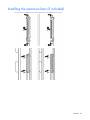
Installing the extension bars (if included)
Installation 38
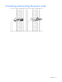
Connecting and securing the power cords
Installation 39
UPS operations
Modes of operation
The UPS has five modes of operation:
•
Standby mode (on page 40)
•
Operate mode (on page 40)
•
Configure mode (on page 41)
•
Battery mode (on page 41)
•
Auto-Bypass mode (on page 41)
Standby mode
In Standby mode:
•
No power is available at the UPS output receptacles.
•
The UPS charges the batteries as necessary.
The UPS can be placed in Standby mode when the UPS is in Operate mode (on page 40).
To place the UPS in Standby mode, press and hold the Off button until the audible alarm sounds and the
Utility LED flashes. Power to the load ceases.
When fault conditions occur in Standby mode, the UPS enters Converter Off mode ("UPS is in Converter Off
mode" on page 57).
IMPORTANT: While in Standby mode, the UPS maintains the charge on the batteries, but no
power is available at the output receptacles. The UPS remains in Standby mode until an alternate
mode is selected or until utility power is removed.
For the location of buttons, see "UPS front panel controls (on page 8)."
For the location of LEDs, see "UPS front panel LED indicators (on page 8)."
Operate mode
In Operate mode:
•
Power is available at the UPS receptacles.
•
The UPS charges the batteries as necessary.
The UPS can be placed in Operate mode if the UPS is powered up and in Standby mode (on page 40).
To place the UPS in Operate mode, press the On button. The Utility LED illuminates, indicating that power is
available at the UPS output receptacles. The UPS acknowledges compliance with a short beep.
If the UPS is off (no LEDs are illuminated), press the On and Battery Start buttons simultaneously to start the
UPS on battery power.
UPS operations
40
For the location of buttons, see "UPS front panel controls (on page 8)."
For the location of LEDs, see "UPS front panel LED indicators (on page 8)."
Configure mode
The UPS can be placed in Configure mode while in Operate mode (on page 40), Battery mode (on page 41)
or Standby mode (on page 40).
In Configure mode:
•
Power is available at the UPS receptacles when entered from Operate mode. Power is not available at
the receptacles when entered from Standby mode.
•
The UPS charges the batteries as necessary.
•
The UPS configuration can be updated.
To place the UPS in Configure mode, press and hold the On and Test/Alarm Reset buttons simultaneously for
3 seconds. The Load Level indicators flash briefly, and then display the enabled options.
For the location of buttons, see "UPS front panel controls (on page 8)."
For the location of LEDs, see "UPS front panel LED indicators (on page 8)."
Battery mode
When utility power is lost, the UPS automatically transfers from Operate mode (on page 40) to Battery mode.
In Battery mode, the UPS supplies power without being connected to utility power. When utility power
becomes available, the UPS returns to Operate mode.
After the UPS is initially connected to utility power, it can be started on battery power thereafter. To start the
UPS in Battery mode (no utility power present), press and hold the On and Battery Start buttons
simultaneously for three seconds.
Auto-Bypass mode
The UPS automatically enters Auto-Bypass mode when one of the following conditions occurs:
•
The power from the UPS reaches a percentage greater than 110 percent for more than 10 cycles or
between 103 percent and 110 percent for more than 30 seconds.
•
The UPS detects an overtemperature condition (on page 59).
•
The UPS detects a fan failure.
•
There is an internal UPS failure while in Operate mode (on page 40).
All internal faults transfer the UPS to either Auto-Bypass or Converter Off mode ("UPS is in Converter Off
mode" on page 57), depending on whether the load is being powered at the time the fault is detected. The
UPS can be forced to Converter Off mode from Auto-Bypass mode by pressing the Off button, and can be
sent back to Auto-Bypass mode by pressing the On button.
Operating the UPS front panel controls
UPS operations
41
NOTE: If the On and Off buttons are simultaneously pressed, the Off button has priority over the
On button.
Button
Assertion
time
Audible alarm
On
0.5 seconds
Off
Self Test
3 seconds
Utility
present ?
Action
Every 0.5 seconds Standby
until the button is
released
Yes
Energizes the load and
resets the bypass entry count
to 0
Operate
Yes
Resets the bypass entry count
to 0
Auto-Bypass
Yes
Clears the UPS On audible
alarms, resets the bypass
entry count to 0, and
attempts to transfer to
Operate mode
Converter Off
Yes
Clears the UPS On audible
alarms, resets the bypass
entry count to 0, and
attempts to transfer to
Operate mode
Every 0.5 seconds Operate
until the button is
released
Yes
Transfers to Standby mode,
and power to the load
ceases
Standby
Yes
No action
Battery
No
Powers down the UPS, and
power to the load ceases
Auto-bypass
Yes or No
Transfers to Standby mode
or Converter Off mode, and
power to the load ceases
Any
Yes or No
Silences audible alarms after
0.5 seconds
Any
Yes or No
Initiates a self-test
Any
Yes or No
No action
0.5 seconds
3 seconds
Continuously
Battery Start 0.5 seconds
Mode before
assertion
Battery Start 3 seconds
and On
Continuously
UPS off
No
Transfers to battery power,
and begins powering the
load
On and Self 3 seconds
Test
Continuously
Any
Yes or No
Enters or exits Configuration
mode
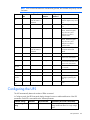
Configuring the UPS
The UPS automatically detects the number of ERMs connected.
In Configure mode, the LED front panel display changes function to enable modification of the UPS
parameters. Each LED is associated with a different parameter.
Available settings
Parameter
Associated LED
Explanation (when LED is illuminated)
Nominal voltage
setting
100/204 Nom
Self Test
Nominal output voltage is 100 V for a low
voltage model and 204 V for a high voltage
model
UPS operations
42
Available settings
Wiring fault setting
Parameter
Associated LED
Explanation (when LED is illuminated)
110/220 Nom
Battery Fault
Nominal output voltage is 110 V for a low
voltage model and 220 V for a high voltage
model
120/230 Nom
Site Wiring Fault
Nominal output voltage is 120 V for a low
voltage model and 230 V for a high voltage
model
127/240 Nom
Overtemperature
Nominal output voltage is 127 V for a low
voltage model and 240 V for a high voltage
model
Wiring fault
Overload
Audible alarm will sound when ground is
missing or line and neutral connections are
reversed
NOTE: For high voltage UPSs, the Site Wiring Fault function is disabled by default, but can be
manually enabled.
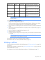
To change the UPS configuration parameters:
1.
Place the UPS in Configure mode (on page 41).
The LEDs associated with the currently configured parameters illuminate. A flashing cursor indicates
where you are in the configuration process as you scroll through the available settings.
2.
Press the On button to scroll through the options. Each time the On button is pressed, the audible alarm
sounds.
3.
If the On button is pressed and the UPS does not respond, the UPS is in Operate mode (on page 40).
Start over with step 1.
4.
Press the Off button once to toggle the selected option on or off.
5.
Repeat steps 2 and 3 for each option.
6.
To save the configuration settings and exit Configure mode, press and hold the Test/Alarm Reset button
for 3 seconds.
NOTE: Configure mode times out after 2 minutes of inactivity. If the Test/Alarm Reset button has
not been pressed, any new selections are not saved.
For the location of buttons, see "UPS front panel controls (on page 8)."
For the location of LEDs, see "UPS front panel LED indicators (on page 8)."
Initiating a self-test
To initiate a self-test, press and hold the Test/Alarm Reset button ("UPS front panel controls" on page 8) for
three seconds.
If the UPS detects a problem, the appropriate LED ("UPS front panel LED indicators" on page 8) illuminates
and an audible alarm may sound.
For information on what to do if the self-test detects a problem, see "Troubleshooting (on page 55)."
UPS operations
43
Silencing an audible alarm
To silence an alarm, press the Test/Alarm Reset button ("UPS front panel controls" on page 8).
IMPORTANT:
• Although the audible alarm silences, the condition that caused the alarm to sound may still
exist.
• If a utility power failure caused the alarm, the alarm silences after power is restored.
For information about audible alarm conditions, see "LED and audible alarm troubleshooting ("LED
troubleshooting" on page 55)."
Verifying the REPO port connection
NOTE: While testing, operate connected equipment in a safe test mode so the effects do not
disrupt critical operations.
After connecting the REPO port (on page 21):
1.
Initiate a REPO by closing the REPO contact.
The Self Test, Battery Fault, Site Wiring Fault, Overtemperature, Overload, and Utility LEDs flash.
CAUTION: If the polarity is reversed while connecting the REPO port, the UPS powers up
normally.
2.
Verify proper connection of the REPO port:
a. Power up the UPS ("Starting power to the load" on page 26).
b. Disconnect the REPO port.
c.
Reconnect the REPO port.
If the polarity is correct, the REPO connectors can be disconnected, and then reconnected, without
initiating a REPO.
d. Verify that the UPS remains in Operate mode (on page 40).
e. If a REPO is initiated, the polarity is reversed. Check and correct the connections.
Powering down the UPS
1.
Shut down all load devices.
2.
Press the Off button to take the UPS out of Operate mode. Power to the load receptacles ceases.
The On Battery LED and Load Level indicator flash.
3.
Disconnect the UPS from utility power.
4.
Wait at least 60 seconds for the UPS internal circuitry to discharge.
UPS operations
44
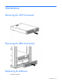
Maintenance
Removing the UPS front bezel
Removing the ERM front bezel
Replacing the batteries
To replace the batteries:
Maintenance
45
1.
Read and observe the requirements in "Important battery safety information (on page 46)" and "Battery
care and storage guidelines (on page 46)."
2.
Follow the instructions in "UPS battery replacement procedure (on page 47)."
Important battery safety information
WARNING: The unit contains sealed lead-acid battery modules. To prevent fire or chemical
burns:
•
•
•
•
•
Do
Do
Do
Do
Do
not
not
not
not
not
attempt to recharge batteries after removal from the unit.
disassemble, crush, or puncture the batteries.
short the external contacts of the batteries.
immerse the batteries in water.
expose to temperatures higher than 60°C (140°F).
WARNING: To prevent personal injury from hazardous energy:
• Remove watches, rings, or other metal objects.
• Use tools with insulated handles.
• Do not place tools or metal parts on top of batteries.
WARNING: To prevent personal injury, prepare the area and observe all materials-handling
procedures when transporting a battery module. Battery modules weigh 20 kg (44.1 lb).
NOTE: Replace all battery modules at the same time.
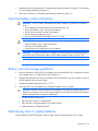
Battery care and storage guidelines
•
Minimize the amount of time the UPS uses battery power by matching the UPS configuration with the
utility voltage. Refer to "Configuring the UPS (on page 42)."
•
Keep the area around the UPS clean and dust-free. If the environment is very dusty, clean the outside of
the UPS regularly with a vacuum cleaner.
•
Maintain the ambient temperature at 25°C (77°F).
•
If storing a UPS for an extended period, recharge the batteries every 6 months:
CAUTION: Because of the short shelf life of the batteries, avoid storing a battery spare as a
backup. Do not maintain an inventory of spare batteries on site unless a procedure to keep these
batteries charged while in storage is implemented.
a. Connect the UPS to utility power.
b. Allow the UPS to remain in Standby mode.
c.
Allow the UPS to charge the batteries for at least 24 hours.
d. Update the battery recharge date label.
Determining when to replace batteries
When the Battery Fault LED illuminates, batteries might need to be replaced within 30 to 60 days.
Maintenance
46
When a battery alarm sounds, initiate a UPS battery self-test to verify that battery replacement is required. If
the Battery Fault LED remains illuminated, replace the batteries as soon as possible.
For more information on initiating a self-test, see "Initiating a self-test (on page 43)."
For the location of LEDs, see "UPS front panel LED indicators (on page 8)."
Obtaining new batteries
New batteries might be required within 30 to 60 days when the Battery Fault LED illuminates red. Obtain
spare batteries for the UPS when this occurs.
Spare battery modules are available for this UPS. The UPS spare battery kit part number is 517703-001.
CAUTION: Because of the short shelf life of the batteries, avoid storing a battery spare as a
backup. Do not maintain an inventory of spare batteries on site unless a procedure to keep these
batteries charged while in storage is implemented.
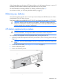
UPS battery replacement procedure
WARNING: To prevent personal injury from electric shock or damage to the equipment, remove
the battery lead labels, and verify that the ERM circuit breakers are in the Off position.
This component is hot-swappable and can be replaced without powering down the UPS.
1.
(optional) To replace the component with the UPS powered down, refer to "Powering down the UPS (on
page 44)."
CAUTION: When hot-swapping batteries, the UPS is not protected in the event of a utility power
failure.
2.
Remove the UPS front bezel ("Removing the UPS front bezel" on page 45).
3.
Disconnect the battery leads.
4.
Remove the UPS battery bracket.
5.
Remove the UPS battery modules.
Maintenance
47
IMPORTANT: Do not pull the battery leads when removing or installing the batteries.
To replace the components, reverse the removal procedure.
IMPORTANT: Charge the batteries for at least 24 hours before supplying backup power to
devices. The batteries charge to:
• 80 percent of their capacity within 3 hours
• 100 percent of their capacity within 48 hours
Testing the new battery module
After installing the new battery module, press the Test/Alarm Reset button to initiate a self-test ("Initiating a
self-test" on page 43).
IMPORTANT: The UPS does not execute a self-test until the batteries are 90 percent charged.
IMPORTANT: Charge the batteries for at least 24 hours before supplying backup power to
devices. The batteries charge to:
• 80 percent of their capacity within 3 hours
• 100 percent of their capacity within 48 hours
If the installation has been successful, the Battery Fault LED is not illuminated. If the installation has not been
successful, the Battery Fault LED illuminates. If this occurs, repeat the UPS battery replacement procedure (on
page 47), and check the battery terminal connections. If the Battery Fault LED is still illuminated, see "LED and
audible alarm troubleshooting ("LED troubleshooting" on page 55)."
For the location of buttons, see "UPS front panel controls (on page 8)."
For the location of LEDs, see "UPS front panel LED indicators (on page 8)."
Maintenance
48
Replacing the UPS
To remove the UPS:
1.
Power down all attached load devices.
2.
Power down the UPS ("Powering down the UPS" on page 44).
3.
Switch the circuit breaker for any attached ERMs to the Off position.
4.
Unplug the UPS power cord.
5.
Disconnect the communications cable from the option card.
6.
Disconnect the ground bonding cable.
7.
Disconnect the REPO port.
8.
Unplug the load devices.
9.
Unplug the ERM connected to the UPS.
10.
Remove the UPS front bezel ("Removing the UPS front bezel" on page 45).
11.
Disconnect the battery leads.
12.
Remove the UPS battery bracket.
13.
Remove the UPS battery modules.
14.
Remove the screws securing the UPS to the rack.
15.
Remove the UPS from the rack.
To replace the component, reverse the removal procedure.
Replacing the ERM
To remove the ERM:
1.
Switch the circuit breaker for any attached ERMs to the Off position.
2.
Unplug the ERM from the back of the UPS.
3.
Unplug the ERM from a second connected ERM.
4.
Remove the front bezel ("Removing the ERM front bezel" on page 45) on the ERM that is being
replaced.
5.
Disconnect the battery leads.
6.
Remove the screws securing the ERM to the rack.
7.
Remove the ERM from the rack.
To replace the component, reverse the removal procedure.
Replacing the UPS option card
This component is hot-swappable and can be replaced without powering down the UPS.
1.
(optional) To replace the component with the UPS powered down, refer to "Powering down the UPS (on
page 44)."
2.
Disconnect the communications cable from the option card.
Maintenance
49
3.
Remove the two screws securing the option card and slide the card out.
To replace the component, reverse the removal procedure.
NOTE: Replacing the option card might require power protector software to be restarted or
reconfigured.
Updating the UPS firmware
To update the UPS firmware, see the HP website (http://www.hp.com/go/rackandpower).
Configuring a USB to serial converter
NOTE: This procedure was tested on the Windows® XP Professional, Windows Server® 2003,
and Windows® Vista Enterprise operating systems using the HP USB to serial converter (part
number 304098-001). Depending on your system configuration, a driver download might be
required to successfully install the converter. The driver can be downloaded from the USB-Drivers
website (http://www.usb-drivers.com/drivers/123/123294.htm).
To configure a USB port to the COM 1 port on systems that do not have available serial ports:
1.
Connect the USB to serial converter to the USB port on your system.
2.
For Windows Vista, click Start, select Control Panel, double-click System and Maintenance, and then
skip to step 4.
-orFor Windows XP, click Start, select Control Panel, click Performance and Maintenance, and then click
System.
-orFor Windows Server, click Start, select Control Panel, and then double-click System.
3.
Click the Hardware tab.
4.
Click Device Manager. The Device Manager screen appears.
Maintenance
50
5.
In the tree displayed in the left panel, click the Ports (COM & LPT) branch to expand.
6.
Double-click the port that is assigned to your USB to serial converter device. This port is usually named
with the device manufacturer's name followed by one of the following:
o
USB to Serial Bridge (COM 4)
o
USB Serial port
o
Communications Port (COM1)
The Port Properties screen appears.
7.
Click the Port Settings tab. The Port Settings screen appears.
8.
Click Restore Defaults. The following default settings appear:
o
Bits per second: 9600
o
Data Bits: 8
o
Parity: None
o
Stop bits: 1
o
Flow control: None
9.
Click Advanced. The Advanced Settings screen appears.
10.
From the COM Port Number drop down menu, select Com 1 for the USB port number, and then click
OK.
If COM 1 is being used by another USB port, the following message appears:
This COM name is being used by another device. Using duplicate names can lead
to inaccessible devices and changed settings. Do you want to continue?
If this message appears, click YES. It might be necessary to disable the program accessing COM 1.
a. Click OK.
b. For Windows Vista, skip to step 13.
11.
For Windows Server, reduce the Receive Buffer and Transmit Buffer to the low setting by scrolling down
to select low (1).
12.
Be sure that the Use FIFO buffers (requires 16550 compatible UART) checkbox is selected.
For Windows XP, the USB settings might be different. Choose the lowest, most dependable Receive and
Transmit buffers by using the list menus, radio buttons, or other selection methods.
13.
Click OK to close the Advanced screen.
14.
Click OK to close the Device Manager screen.
15.
Run the firmware Flash batch file program. Follow the instructions provided with the program.
Reassigning the USB COM ports
To reassign a device from COM 1 to another port:
1.
From the open Device Manager screen, locate the USB device that is assigned to COM 1.
2.
Double-click the port name.
The Port Properties screen appears.
3.
Click the Port Settings tab.
The Port Settings screen appears.
4.
Click Advanced.
Maintenance
51
The Advanced Settings screen appears.
5.
Select an available USB port number from the COM Port Number drop down menu.
6.
Click OK to close the Advanced screen.
7.
Click OK to close the Port Settings screen.
8.
Verify that the Device Manager screen shows that the USB to serial converter is assigned to COM 1,
and that the other USB device is assigned to a different port.
If the Device Manager screen does not automatically refresh to show the change:
a. Click Action.
The Action Menu appears.
b. Click Scan for hardware changes to refresh the screen and display the changes.
Maintenance
52
Power management
Power Protector software
HP Power Protector software ensures maximum power reliability of computer systems through comprehensive
control of UPSs. The easy-to-use browser interface enables novice users to configure and manage power
protection settings. To download the latest version of HP Power Protector software, see the HP website
(http://www.hp.com/go/rackandpower).
NOTE: To install and configure the software, see the software user guide. The software user
guide is available for download from the HP website (http://www.hp.com/go/rackandpower).
HP Power Protector:
•
Does not require complex management systems, which simplifies deployment, configuration, and
management of UPS-protected environments.
•
Manages a graceful shutdown of attached devices during utility power failures.
•
Prioritize the shutdown timing of attached computers.
•
Customizes alert generation with modifiable dialog boxes, command execution, and email and
broadcast messages.
•
Monitors the status of the UPS and reports alarms.
•
Displays a power log for analysis.
•
Manages independent UPS load segments to provide separate power control of attached load devices.
The HP UPS Network Module (P/N AF465A) is a Minislot with an easy-to-use browser interface, which gives
you comprehensive control of the UPS and enables you to monitor and effectively manage power
environments. The UPS Network Module supports either a single UPS configuration or a dual redundant UPS
configuration for no single-point-of-failure.
The UPS Network Module can be configured to send alert traps to HP Systems Insight Manager and other
SNMP management programs or used as a stand-alone management system. This flexibility enables you to
monitor and manage UPSs through the network. To facilitate day-by-day maintenance tasks, the embedded
management software provides detailed system logs.
The UPS Network Module provides remote management of a UPS by connecting the UPS directly to the
network. Configuration and management of the UPS from anywhere and at any time through a standard web
browser.
The UPS Network Module (Minislot) is ideal for:
•
Small to enterprise-sized customers that will benefit from remotely managing their UPS.
•
Adding protection via the redundant UPS configuration.
•
Gracefully performing scheduled shut-downs of attached equipment.
•
Notifying administrative personnel in the event of a power failure.
•
Prioritizes the timing of attached load device shutdowns.
Power management 53
•
Delays reboot by load segment after a power outage to sequence the startup of system components.
Power management 54
Troubleshooting
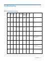
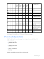
LED troubleshooting
Utility
LED
On
On
Battery Bypass
LED
LED
Self Test
LED
Over
Battery Site
Temp
Fault LED Wiring
Fault LED LED
Overload Condition
LED
On—Lo
ad
<10%
Off
Off
On—Loa
d >10%
On—Loa
d >25%
On—Loa
d >50%
On—Loa
d >75%
Off
UPS is in Operate mode (on
page 40)
Flashing Off
Off
Off
*
*
*
Off
UPS is in Standby mode (on
page 40)
Off
On
On—Loa
d >10%
On—Loa
d >25%
On—Loa
d >50%
On—Loa
d >75%
Off
UPS is in Auto-Bypass mode
(on page 41)
Off
Off
Off
Off
UPS is in Converter Off mode
(on page 57)
Off
Off
Flashing
Flashing
General alarm condition (on
page 57)—UPS is in
Auto-Bypass mode
Off
Flashing Flashing Flashing Off
Off
Off
Off
Off
On
Off
Flashing *
*
*
*
*
Bypass is out of range (on page
58)
*
Off
*
Off
Flashing
*
*
*
Battery condition (on page
58)—Batteries are
disconnected or battery test
failure
Off
Flashing Off
Off
Off
Off
Off
Off
Low battery (no utility power)
("UPS is on battery" on page
58)
Troubleshooting
55
Off
On
Off
On—Batt
ery
capacity
<25%
On—Batt
ery
capacity
>25%
On—Batt
ery
capacity
>50%
On—Batt Off
ery
capacity
>75%
UPS is on battery (on page
58)—No utility power
*
*
*
Off
*
*
Flashing
*
Overtemperature condition (on
page 59)
Off
Off
On
Flashing
Flashing
Flashing
Flashing
Flashing
Internal UPS fault condition (on
page 59)
Flashing Off
Off
Flashing
Flashing
Flashing
Flashing
Flashing
REPO condition (on page 59)
*
Off
*
Off
*
Flashing
*
*
Site wiring condition (on page
59)
*
Off
*
On
On
On
On
Flashing
Overload condition (on page
59)—UPS power capacity is
exceeded with no other faults
*
Off
*
Off
*
*
*
Flashing
Overload condition (on page
59)—UPS power capacity is
exceeded while other faults
exist
Off
On
Off
On—Batt
ery
capacity
<25%
On—Batt
ery
capacity
>25%
On—Batt
ery
capacity
>50%
On—Batt Flashing
ery
capacity
>75%
Overload condition (on page
59)—UPS power capacity is
exceeded while on battery with
no other faults
Off
On
Off
Off
Off
Off
Flashing
Flashing
Overload condition (on page
59)—UPS power capacity is
exceeded while on battery with
overtemperature fault
Off
Flashing Off
Flashing
Flashing
Flashing
Flashing
Flashing
Unit is powering down
Flashing Flashing Flashing Flashing
Flashing
Flashing
Flashing
Flashing
Checksum failure error (on
page 60)
* This LED can be in any state.
For the location of individual LEDs, see "UPS front panel LED indicators (on page 8)."
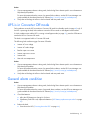
UPS is in Auto-Bypass mode
The UPS transfers from Operate mode (on page 40) to Auto-Bypass when one of the following fault
conditions is detected:
•
Inverter AC over voltage
•
Inverter AC under voltage
•
Rectifier input over current
•
Inverter output over current
•
Inverter fault
•
Heat sink over temperature
•
Fan failure
•
Overload
The load is supported, but not protected while in Auto-Bypass mode.
Troubleshooting
56
Action:
1.
If power management software is being used, check the log files to obtain specific error information to
help identify the problem.
For more information about the causes of a general fault condition, see the HP Power Manager user
guide available for download from the HP website (http://www.hp.com/go/rackandpower).
2.
Verify that no blockage of airflow to the front bezel and rear panel exists.
UPS is in Converter Off mode
Fault conditions cause the UPS to transfer to Converter Off mode from Standby mode (on page 40) only. If
the UPS is powering the load, fault conditions cause the UPS to transfer to Auto-Bypass mode instead.
If a fault condition exist and the UPS is running in Auto-Bypass mode (on page 41), press the Off button to
transfer the UPS to Converter Off mode.
The load is not supported while in Converter Off mode.
The following fault conditions trigger Converter Off mode:
•
Inverter AC over voltage
•
Inverter AC under voltage
•
Rectifier input over current
•
Inverter output over current
•
Inverter fault
•
Heat sink over temperature
Action:
1.
If power management software is being used, check the log files to obtain specific error information to
help identify the problem.
For more information about the causes of a general fault condition, see the HP Power Manager user
guide available for download from the HP website (http://www.hp.com/go/rackandpower).
2.
Verify that no blockage of airflow to the front bezel and rear panel exists.
General alarm condition
Action:
1.
If power management software is being used, check the log files to obtain specific error information to
help identify the problem.
For more information about the causes of a general alarm condition, see the HP Power Manager user
guide available for download from the HP website (http://www.hp.com/go/rackandpower).
2.
Check the batteries:
a. Allow the UPS batteries to charge for 24 hours.
b. If the Battery Fault LED is red, replace the batteries ("UPS battery replacement procedure" on page
47).
3.
Reduce the load:
a. Power down the UPS ("Powering down the UPS" on page 44).
Troubleshooting
57
b. Remove one or more load devices to reduce the power requirements.
c.
Wait at least 5 seconds and restart the UPS.
d. If the condition persists, verify that the load devices are not defective.
4.
Allow the UPS to cool:
a. Power down the UPS ("Powering down the UPS" on page 44).
b. Clear vents and remove any heat sources.
c.
Verify that the airflow around the UPS is not restricted.
5.
Wait at least 5 minutes and restart the UPS.
6.
If the condition persists, contact an HP authorized service representative.
Bypass is out of range
The input voltage is not within ±12 percent of nominal voltage.
The UPS is receiving utility power that might be unstable or in brownout conditions. The UPS continues to
supply power to the connected equipment. If conditions worsen, the UPS might switch to battery power.
Bypass out of range is only a status and does not keep the UPS from transferring to Auto-Bypass mode (on
page 41).
Action:
1.
Check the input voltage and reconfigure the UPS ("Configuring the UPS" on page 42).
2.
Contact a qualified electrician to verify that the utility power is suitable for the UPS.
Battery condition
Action:
1.
Install the battery module. If the battery module is already installed, remove and reinsert the module.
2.
Allow the UPS batteries to charge for 24 hours.
3.
If the LED does not turn off, replace the batteries ("UPS battery replacement procedure" on page 47).
4.
If the condition persists, contact an HP authorized service representative.
UPS is on battery
Action:
1.
Save files and shut down connected equipment.
2.
Allow the UPS batteries to charge for 24 hours.
Input voltage is out of range
Action:
1.
Check the input voltage and reconfigure the UPS ("Configuring the UPS" on page 42).
2.
Contact a qualified electrician to verify that the utility power is suitable for the UPS.
Troubleshooting
58
Overtemperature condition
Possible cause: The UPS internal temperature is too high, or a fan has failed.
Action:
1.
Power down the UPS ("Powering down the UPS" on page 44).
2.
Allow the UPS to cool:
a. Clear vents and remove any heat sources.
b. Be sure that the that the airflow around the UPS is not restricted.
3.
Wait at least 5 minutes, and then restart the UPS.
4.
If the condition persists, contact an HP authorized service representative.
Internal UPS fault condition
Action:
1.
Power down the UPS ("Powering down the UPS" on page 44).
2.
If the condition persists, contact an HP authorized service representative.
REPO condition
Action:
•
If the remote switch is closed, then open the switch to enable power to the output receptacles.
•
If the condition occurred while reconnecting a disconnected REPO port, then verify the polarity of the
REPO connector pins.
For more information about REPO ports, see "Connecting the REPO port (on page 21)."
Site wiring condition
Action: Contact a qualified electrician to be sure that:
•
The line and neutral wires are not reversed in the wall outlet.
•
A ground wire connection does not exist.
Overload condition
All the load LEDs are illuminated.
Action:
1.
Power down the UPS ("Powering down the UPS" on page 44).
2.
Remove one or more load devices to reduce the power requirements.
3.
Wait at least 5 seconds and restart the UPS.
4.
If the condition persists, verify that the load devices are not defective.
Troubleshooting
59
Checksum failure error
A Checksum failure error occurs when executing a bad load sequence, or having an incorrect EEPROM map
while loading software through the serial or USB port.
Action:
1.
Rerun the firmware upgrade.
2.
If the condition persists, contact an HP authorized service representative.
UPS does not start
Action:
1.
Be sure that the power cord is plugged in to a utility power receptacle.
2.
Check the power source at the utility power receptacle.
Low battery shutdowns
Ungraceful shutdown of attached servers occurs when the UPS is in a low battery condition.
Action:
1.
Verify that the power management software is not delaying the shutdown of attached servers when the
UPS is in a low battery condition.
2.
Allow the UPS batteries to charge for 24 hours.
3.
If the Battery Fault LED is red, replace the batteries ("UPS battery replacement procedure" on page 47).
UPS does not provide the expected backup time
Action:
1.
If the Overload LED ("UPS front panel controls" on page 8) is illuminated, remove one or more load
devices to reduce the power requirements.
2.
Power down the UPS ("Powering down the UPS" on page 44).
3.
Allow the UPS batteries to charge for 24 hours.
4.
Initiate a self-test ("Initiating a self-test" on page 43).
5.
During extended power outages, save your work, power down the load devices, and then power down
the UPS ("Powering down the UPS" on page 44) to conserve battery power.
UPS frequently switches between utility and battery
power
Action:
1.
Check the input voltage and reconfigure the UPS ("Configuring the UPS" on page 42).
2.
Contact a qualified electrician to verify that the utility power is suitable for the UPS.
Troubleshooting
60
Specifications
UPS physical specifications
Parameter
Value
Height
8.9 cm (3.5 in)
Depth
63.5 cm (25 in)
Width
44.5 cm (17.5 in)
Weight
37 kg (82 lb)
ERM physical specifications
Parameter
Value
Height
8.9 cm (3.5 in)
Depth
63.5 cm (25 in)
Width
44.5 cm (17.5 in)
Weight
45 kg (100 lb)
UPS input specifications
UPS model
Utility voltage
frequency (Hz)
Available settings utility Branch circuit
voltage (VAC)
rating (A)
Line cord
R/T3000
NA/JPN
50/60
100, 110, 120, 127
30
Nondetachable power
cord with NEMA L5-30
plug
R/T3000h
NA/JPN
50/60
200/2081, 220, 230,
240
20
Nondetachable power
cord with NEMA L6-20
plug
R/T3000 INTL
50/60
200/208, 220, 230,
240
16
Detachable power cord
with country-specific plug
1
The output voltage is 204 for this setting.
UPS output specifications
UPS model
Load segment
Output receptacles
R/T3000 NA/JPN
1
2 x 5-20R T-Slot
—
—
1 x L5-30R
—
2
2 x 5-20R T-Slot
R/T3000h NA/JPN
1
3 x IEC-320-C13
—
—
1 x IEC-320-C19
Specifications
61
UPS model
Load segment
Output receptacles
—
—
1 x L6-20R
—
2
3 x IEC-320-C13
—
—
1 x IEC-320-C19
R/T3000 INTL
1
3 x IEC-320-C13
—
—
1 x IEC-320-C19
—
2
3 x IEC-320-C13
—
—
1 x IEC-320-C19
Power protection specifications
UPS model
VA
R/T3000 NA/JPN 2880 /
2400
3300
R/T3000h
Nominal power
rating (W)
Nominal voltage setting
2700 / 2250
120/100
3000
204
3000
230
NA/JPN
R/T3000 INTL
3300
Output tolerance specifications
Source of power
Regulation
Utility power (nominal
range)
-10% to +6% of nominal output voltage rating
(within the guidelines of the Computer Business
Equipment Manufacturers Association)
Battery power
±5% of nominal output voltage rating
Output feature specifications
Feature
Specification
Online efficiency
94% nominal input voltage
Voltage wave shape
Sine wave; 5% THD with typical PFC load
Surge suppression
300J via MOVs
Noise filtering
EN 55022 line filter for normal and common mode
use
Battery specifications
Feature
Specification
Type
12 V, 5 AH, sealed, maintenance-free, rechargeable, valve
regulated lead-acid batteries with a 3-5 year service life at 25°C
(77°F).
Voltage
The battery modules have a battery string voltage of 120 V.
Specifications
62
Feature
Specification
Charging
Complete charge takes no more than 48 hours. After
approximately 3 hours, the batteries reach 80% charge at default
nominal utility voltage and no load.
High-voltage UPS battery runtimes
Load, percent
Estimated battery
runtime
Runtime with one ERM
Runtime with two ERMs
20
40 minutes
125 minutes
225 minutes
50
12 minutes
50 minutes
89 minutes
80
6 minutes
30 minutes
54 minutes
100
4 minutes
24 minutes
43 minutes
Low-voltage UPS battery runtimes
Load, percent
Estimated battery
runtime
Runtime with one ERM
Runtime with two ERMs
20
45 minutes
142 minutes
256 minutes
50
15.5 minutes
55 minutes
99 minutes
80
7 minutes
34 minutes
60 minutes
100
5 minutes
26 minutes
47 minutes
Environmental specifications
Feature
Specification
Operating temperature
10°C to 40°C (50°F to 104°F); UL-tested at 25°C
(77°F)
Nonoperating
temperature
-15°C to 40°C (-5°F to 104°F)
Relative humidity
20% to 80%; noncondensing
Operating altitude
Up to 3,000 m (9,842 ft) above sea level
Nonoperating altitude
15,000 m (49,212 ft) above sea level
Audible noise
Less than 45 dBA, normal operation
Less than 50 dBA, on battery power
REPO port specifications
The REPO port meets the requirements of NFPA 70 and NEC Articles 645-10 and 645-11 for a
Disconnecting Means.
Specifications
63
Spares
Ordering spares
To order a spare, visit the HP website (http://www.hp.com/buy/parts).
To replace parts under warranty, contact an HP authorized service representative.
UPS spare parts list
Item
Description
Spare part number
1
UPS unit
—
a) NA/JPN
638840-001
b) HV NA/JPN*
638841-001
c) INTL*
638842-001
2
UPS Network Module
636934-001
3
Battery module
517703-001
4
Mounting rails with screws*
419181-001
5
UPS/ERM mounting brackets*
582931-001
6
Cord retention clips (6)*
407409-001
7
Serial download cable*
397642-001
* not shown
Spares
64
ERM spare parts list
Item
Description
Spare part number
1
ERM unit
517702-001
2
UPS/ERM mounting
582931-001
brackets*
Mounting rails with screws* 419181-001
3
* not shown
Hardware options
For information on the supported hardware options, see the HP website
(http://www.hp.com/go/rackandpower).
Spares
65
Support and other resources
Before you contact HP
Be sure to have the following information available before you call HP:
•
Active Health System log
Download and have available an Active Health System log for 3 days before the failure was detected.
For more information, see the HP iLO 4 User Guide or HP Intelligent Provisioning User Guide on the HP
website (http://www.hp.com/go/ilo/docs).
•
Onboard Administrator SHOW ALL report (for HP BladeSystem products only)
For more information on obtaining the Onboard Administrator SHOW ALL report, see the HP website
(http://h20000.www2.hp.com/bizsupport/TechSupport/Document.jsp?lang=en&cc=us&objectID=c
02843807).
•
Technical support registration number (if applicable)
•
Product serial number
•
Product model name and number
•
Product identification number
•
Applicable error messages
•
Add-on boards or hardware
•
Third-party hardware or software
•
Operating system type and revision level
HP contact information
For United States and worldwide contact information, see the Contact HP website
(http://www.hp.com/go/assistance).
In the United States:
•
To contact HP by phone, call 1-800-334-5144. For continuous quality improvement, calls may be
recorded or monitored.
•
If you have purchased a Care Pack (service upgrade), see the Support & Drivers website
(http://www8.hp.com/us/en/support-drivers.html). If the problem cannot be resolved at the website,
call 1-800-633-3600. For more information about Care Packs, see the HP website
(http://pro-aq-sama.houston.hp.com/services/cache/10950-0-0-225-121.html).
Support and other resources
66
Warranty information
Limited warranty
To back up the wide range of features offered with the UPS, a 3-year limited warranty is provided.
$250,000 Computer Load Protection Guarantee
In addition to the limited warranty, a $250,000 Computer Load Protection Guarantee (provided by the
original equipment manufacturer) is offered.
IMPORTANT: The $250,000 Computer Load Protection Guarantee is offered only in The United
States and Canada.
The $250,000 Computer Load Protection Guarantee only applies if:
•
The UPS is plugged into a suitably grounded and wired outlet using no extension cords, adapters, other
ground wires, or other electrical connections.
•
The UPS installation complies with all applicable electrical and safety codes specified by the NEC.
•
The UPS is used under normal operating conditions and users comply with all instructions and labels.
•
The UPS is not damaged by accident (other than a utility power transient), misuse, or abuse.
•
o
The Guarantee applies only to the original end-user and is non-transferable.
o
The Guarantee does not include reimbursement for or restoration of any data loss.
The UPS is either connected directly to an enterprise class PDU, which is then connected directly to a
server, workstation, or personal computer, or the UPS is connected directly to a server, workstation, or
personal computer.
Pre-Failure Battery Warranty
The Pre-Failure Battery Warranty, standard on all UPS units, extends the advantage of a 3-year limited
warranty by applying it to the battery before it actually fails. The Pre-Failure Battery Warranty ensures that the
battery is replaced free of charge when a notification that the battery might fail is received from power
protector software. The battery warranty coverage is 3 years for parts. The warranty for the first year of
ownership includes parts and labor. If battery spares are not available for a particular UPS model, the entire
UPS, including its battery, is replaced.
A Pre-Failure Battery warning is given 30 days before a battery failure. The warning is indicated in one or
both of the following ways:
•
An LED showing the battery is low
•
Notification from power protector software
Warranty information 67
Recommended duration of use
Although tests and a multitude of customer experiences have shown no noticeable performance issues with
UPSs for significant time periods after expiration of the 3-year limited warranty, we strongly recommend
considering replacing UPSs after a maximum of 5 to 6 years of use to assure full functionality and a safe
operating environment. This recommendation does not extend or in any way alter the warranty for UPSs
which is limited to a time period of 3 years and a coverage as stated in the applicable warranty statement.
Warranty information 68
Regulatory compliance notices
Regulatory compliance identification numbers
For the purpose of regulatory compliance certifications and identification, this product has been assigned a
unique regulatory model number. The regulatory model number can be found on the product nameplate
label, along with all required approval markings and information. When requesting compliance information
for this product, always refer to this regulatory model number. The regulatory model number is not the
marketing name or model number of the product.
Federal Communications Commission notice
Part 15 of the Federal Communications Commission (FCC) Rules and Regulations has established Radio
Frequency (RF) emission limits to provide an interference-free radio frequency spectrum. Many electronic
devices, including computers, generate RF energy incidental to their intended function and are, therefore,
covered by these rules. These rules place computers and related peripheral devices into two classes, A and
B, depending upon their intended installation. Class A devices are those that may reasonably be expected
to be installed in a business or commercial environment. Class B devices are those that may reasonably be
expected to be installed in a residential environment (for example, personal computers). The FCC requires
devices in both classes to bear a label indicating the interference potential of the device as well as additional
operating instructions for the user.
FCC rating label
The FCC rating label on the device shows the classification (A or B) of the equipment. Class B devices have
an FCC logo or ID on the label. Class A devices do not have an FCC logo or ID on the label. After you
determine the class of the device, refer to the corresponding statement.
FCC Notice, Class A Equipment
This equipment has been tested and found to comply with the limits for a Class A digital device, pursuant to
Part 15 of the FCC Rules. These limits are designed to provide reasonable protection against harmful
interference when the equipment is operated in a commercial environment. This equipment generates, uses,
and can radiate radio frequency energy and, if not installed and used in accordance with the instructions,
may cause harmful interference to radio communications. Operation of this equipment in a residential area
is likely to cause harmful interference, in which case the user will be required to correct the interference at
personal expense.
FCC Notice, Class B Equipment
This equipment has been tested and found to comply with the limits for a Class B digital device, pursuant to
Part 15 of the FCC Rules. These limits are designed to provide reasonable protection against harmful
interference in a residential installation. This equipment generates, uses, and can radiate radio frequency
energy and, if not installed and used in accordance with the instructions, may cause harmful interference to
Regulatory compliance notices
69
radio communications. However, there is no guarantee that interference will not occur in a particular
installation. If this equipment does cause harmful interference to radio or television reception, which can be
determined by turning the equipment off and on, the user is encouraged to try to correct the interference by
one or more of the following measures:
•
Reorient or relocate the receiving antenna.
•
Increase the separation between the equipment and receiver.
•
Connect the equipment into an outlet on a circuit that is different from that to which the receiver is
connected.
•
Consult the dealer or an experienced radio or television technician for help.
Declaration of conformity for products marked with
the FCC logo, United States only
This device complies with Part 15 of the FCC Rules. Operation is subject to the following two conditions: (1)
this device may not cause harmful interference, and (2) this device must accept any interference received,
including interference that may cause undesired operation.
For questions regarding this product, contact us by mail or telephone:
•
Hewlett-Packard Company
P. O. Box 692000, Mail Stop 530113
Houston, Texas 77269-2000
•
1-800-HP-INVENT (1-800-474-6836). (For continuous quality improvement, calls may be recorded or
monitored.)
For questions regarding this FCC declaration, contact us by mail or telephone:
•
Hewlett-Packard Company
P. O. Box 692000, Mail Stop 510101
Houston, Texas 77269-2000
•
1281-514-3333
To identify this product, refer to the part, series, or model number found on the product.
Modifications
The FCC requires the user to be notified that any changes or modifications made to this device that are not
expressly approved by Hewlett-Packard Company may void the user’s authority to operate the equipment.
Cables
Connections to this device must be made with shielded cables with metallic RFI/EMI connector hoods in
order to maintain compliance with FCC Rules and Regulations.
Canadian notice (Avis Canadien)
Class A equipment
Regulatory compliance notices
70
This Class A digital apparatus meets all requirements of the Canadian Interference-Causing Equipment
Regulations.
Cet appareil numérique de la classe A respecte toutes les exigences du Règlement sur le matériel brouilleur
du Canada.
Class B equipment
This Class B digital apparatus meets all requirements of the Canadian Interference-Causing Equipment
Regulations.
Cet appareil numérique de la classe B respecte toutes les exigences du Règlement sur le matériel brouilleur
du Canada.
European Union regulatory notice
Products bearing the CE marking comply with the following EU Directives:
•
Low Voltage Directive 2006/95/EC
•
EMC Directive 2004/108/EC
•
Ecodesign Directive 2009/125/EC, where applicable
CE compliance of this product is valid if powered with the correct CE-marked AC adapter provided by HP.
Compliance with these directives implies conformity to applicable harmonized European standards
(European Norms) that are listed in the EU Declaration of Conformity issued by HP for this product or product
family and available (in English only) either within the product documentation or at the following HP website
(http://www.hp.eu/certificates) (type the product number in the search field).
The compliance is indicated by one of the following conformity markings placed on the product:
For non-telecommunications products and for EU harmonized telecommunications products, such as
Bluetooth® within power class below 10mW.
For EU non-harmonized telecommunications products (If applicable, a 4-digit notified body number is
inserted between CE and !).
Please refer to the regulatory label provided on the product.
The point of contact for regulatory matters is Hewlett-Packard GmbH, Dept./MS: HQ-TRE, Herrenberger
Strasse 140, 71034 Boeblingen, GERMANY.
Disposal of waste equipment by users in private
households in the European Union
Regulatory compliance notices
71
This symbol on the product or on its packaging indicates that this product must not be disposed of
with your other household waste. Instead, it is your responsibility to dispose of your waste
equipment by handing it over to a designated collection point for the recycling of waste electrical
and electronic equipment. The separate collection and recycling of your waste equipment at the
time of disposal will help to conserve natural resources and ensure that it is recycled in a manner
that protects human health and the environment. For more information about where you can drop
off your waste equipment for recycling, please contact your local city office, your household
waste disposal service or the shop where you purchased the product.
Japanese notice
BSMI notice
Korean notice
Class A equipment
Regulatory compliance notices
72
Class B equipment
Chinese notice
Class A equipment
Battery replacement notice
WARNING: Power products contain sealed lead-acid battery modules. A risk of fire and burns
exists if the battery is not properly handled. To reduce the risk of personal injury:
• Do not attempt to recharge the battery.
• Do not expose the battery to temperatures higher than 60°C (140°F).
• Do not disassemble, crush, puncture, short external contacts, or dispose of in fire or water. The
battery might explode.
Batteries, battery packs, and accumulators should not be disposed of together with the general
household waste. To forward them to recycling or proper disposal, use the public collection system or
return them to HP, an authorized HP Partner, or their agents.
For more information about battery replacement or proper disposal, contact an authorized reseller or an
authorized service provider.
Taiwan battery recycling notice
The Taiwan EPA requires dry battery manufacturing or importing firms in accordance with Article 15 of the
Waste Disposal Act to indicate the recovery marks on the batteries used in sales, giveaway or promotion.
Contact a qualified Taiwanese recycler for proper battery disposal.
Regulatory compliance notices
73
Power cord statement for Japan
Regulatory compliance notices
74
Electrostatic discharge
Preventing electrostatic discharge
To prevent damaging the system, be aware of the precautions you need to follow when setting up the system
or handling parts. A discharge of static electricity from a finger or other conductor may damage system
boards or other static-sensitive devices. This type of damage may reduce the life expectancy of the device.
To prevent electrostatic damage:
•
Avoid hand contact by transporting and storing products in static-safe containers.
•
Keep electrostatic-sensitive parts in their containers until they arrive at static-free workstations.
•
Place parts on a grounded surface before removing them from their containers.
•
Avoid touching pins, leads, or circuitry.
•
Always be properly grounded when touching a static-sensitive component or assembly.
Grounding methods to prevent electrostatic discharge
Several methods are used for grounding. Use one or more of the following methods when handling or
installing electrostatic-sensitive parts:
•
Use a wrist strap connected by a ground cord to a grounded workstation or computer chassis. Wrist
straps are flexible straps with a minimum of 1 megohm ±10 percent resistance in the ground cords. To
provide proper ground, wear the strap snug against the skin.
•
Use heel straps, toe straps, or boot straps at standing workstations. Wear the straps on both feet when
standing on conductive floors or dissipating floor mats.
•
Use conductive field service tools.
•
Use a portable field service kit with a folding static-dissipating work mat.
If you do not have any of the suggested equipment for proper grounding, have an authorized reseller install
the part.
For more information on static electricity or assistance with product installation, contact an authorized
reseller.
Electrostatic discharge
75
Acronyms and abbreviations
EEPROM
electrical erasable programmable read only memory
ERM
extended runtime module
IEC
International Electrotechnical Commission
MOV
metal oxide varistor
PDU
power distribution unit
PFC
power factor corrected
REPO
remote emergency power off
THD
total harmonic distortion
UPS
uninterruptible power system
USB
universal serial bus
Acronyms and abbreviations
76
Documentation feedback
HP is committed to providing documentation that meets your needs. To help us improve the documentation,
send any errors, suggestions, or comments to Documentation Feedback (mailto:[email protected]).
Include the document title and part number, version number, or the URL when submitting your feedback.
Documentation feedback
77
Index
A
alarms, silencing 44
authorized reseller 66
Auto-Bypass mode 41, 56
B
backup time, insufficient 60
batteries, care and storage 46
batteries, charging 25, 30
batteries, connecting 18, 27
batteries, obtaining 47
batteries, replacing 45, 46, 47
batteries, runtime 63
batteries, specifications 62
batteries, testing 48
battery bracket 47
battery condition 58
Battery Fault LED, location 8
Battery Fault LED, troubleshooting 55
Battery mode 41
battery replacement notice 73
battery warranty 67
bezel, attaching 28, 35
bezel, removing 45
bracket, battery 47
BSMI notice 72
bypass is out of range 58
C
cables 70
Canadian notice 70
charging batteries 25, 30
checksum failure error 60
circuit breakers, switching on 30
class A equipment 69
class B equipment 69
components, identification 7, 8
configuration of system 42
Configure mode 41
connecting batteries 18, 27
contacting HP 66
Converter Off mode 57
converter, serial to USB 50
D
Declaration of Conformity 70
devices, connecting 24, 39
diagnostics 43
dimensions, ERM 61
dimensions, UPS 61
disposal, battery 71, 73
duration of use 68
E
electrical requirements 14
electrostatic discharge 75
environmental specifications 63
ERM circuit breaker, turning on 30
ERM, identifying components 12
ERM, installing 26, 35
ERM, replacing 49
European Union notice 71
extension bars, installing 38
F
FCC rating label 69
Federal Communications Commission (FCC)
notice 69, 70
firmware, updating 50
frequent switching between battery and utility
power 60
front panel buttons 8
front panel components 7, 8
front panel LEDs 8
front panel, 41
G
general alarm condition 57
grounding methods 75
H
hardware options 65
hardware, preparing to install 13
Index
78
HP technical support 66
I
input specifications 61
input voltage is out of range 58
installation instructions 13, 17, 26, 32, 35
installing the ERM 26, 35
installing the UPS 17, 32
internal UPS fault condition 59
J
Japanese notice 72
K
Korean notices 72
L
LEDs, testing 43
LEDs, troubleshooting 55
limited warranty 67
load protection guarantee 67
low battery shutdowns 60
M
maintenance 45
modes of operation 40, 57
modifications, FCC notice 70
N
nominal voltage, configuring 42
O
obtaining new batteries 47
On Battery LED, location 8
On Battery LED, troubleshooting 55
On button, location 8
On Bypass LED, troubleshooting 55
Operate mode 40
operating front panel controls 41
operations, UPS 40
optional items 65
ordering spares 64
output feature specifications 62
output specifications 61
output tolerance specifications 62
overload condition 59
Overload LED, location 8
Overload LED, troubleshooting 55
Overtemperature LED, location 8
Overtemperature LED, troubleshooting 55
overview, REPO port 11
P
phone numbers 66
physical specifications 61
power cord 74
power management 53
power protection specifications 62
powering down 44
preparation procedures 13
R
R/T3000 ERM 12
R/T3000 models 9
rack-to-tower conversion 32, 35
rear panel connectors 12
recommended duration of use 68
regulatory compliance identification numbers 69
regulatory compliance notices 69, 71, 73
replacing the batteries 45, 47
replacing the ERM 49
replacing the UPS 49
REPO condition 59
REPO port, overview 11
REPO port, specifications 63
REPO port, verifying connection 44
required information 66
required tools 13
Reset button, location 8
runtime specifications 63
S
safety considerations 13, 46
selecting a site 14
series number 69
site requirements 14
site wiring condition 59
Site Wiring Fault LED, location 8
Site Wiring Fault LED, troubleshooting 55
spares 64
specifications 61
Standby mode 40
static electricity 75
storing batteries 46
support 66
supported hardware 65
Index
79
system configuration settings 42
T
Taiwan battery recycling notice 73
technical support 66
telephone numbers 66
temperature ranges (environmental) 63
Test/Alarm Reset button, location 8
testing batteries 48
tools 13
tower bezel, installing 35
tower conversion stands 35
troubleshooting 55
U
updating the firmware 50
UPS does not start 60
UPS firmware, updating 50
UPS is on battery 58
UPS operations 40
UPS, configuring 42
UPS, installing 13, 17, 32
UPS, replacing 49
Utility LED, location 8
Utility LED, troubleshooting 55
utility power, connecting 24
V
voltage, configuring 42
W
warranties 67
weight, battery 46
weight, ERM 61
weight, UPS 61
Index
80