1
HP UPS R5500
User Guide
June 2006 (Third Edition)
Part Number 351643-003
© Copyright 2003, 2006 Hewlett-Packard Development Company, L.P.
The information contained herein is subject to change without notice. The only warranties for HP products and services are set forth in the express
warranty statements accompanying such products and services. Nothing herein should be construed as constituting an additional warranty. HP
shall not be liable for technical or editorial errors or omissions contained herein.
June 2006 (Third Edition)
Part Number 351643-003
Audience assumptions
This guide is for the person who operates, configures, maintains, and troubleshoots UPSs. HP assumes
you are qualified in the servicing of high-voltage equipment and trained in recognizing hazards in
products with hazardous energy levels.
Contents
Component identification ............................................................................................................... 6
UPS
UPS
UPS
UPS
UPS
R5500 overview................................................................................................................................. 6
front panel ......................................................................................................................................... 6
front panel controls ............................................................................................................................. 7
front panel LED indicators .................................................................................................................... 8
rear panel ......................................................................................................................................... 9
REPO port ...................................................................................................................................... 9
ERM rear panel....................................................................................................................................... 10
Installation ................................................................................................................................. 11
Precautions............................................................................................................................................. 11
Preparing to install the hardware............................................................................................................... 11
Tools and materials........................................................................................................................ 12
Selecting a site.............................................................................................................................. 12
Readying the equipment ................................................................................................................. 12
Installing the mounting rails ...................................................................................................................... 13
Preparing the rails for integrated shipping .................................................................................................. 15
Installing the UPS..................................................................................................................................... 15
Removing the UPS battery bracket ................................................................................................... 16
Installing the batteries..................................................................................................................... 17
Replacing the UPS battery bracket ................................................................................................... 17
Attaching the UPS front bezel.......................................................................................................... 18
Switching on the UPS battery circuit breaker ..................................................................................... 18
Connecting the serial communications port ....................................................................................... 18
Connecting the REPO port .............................................................................................................. 19
Connecting the ground bonding cable ............................................................................................. 21
Connecting the UPS to utility power ................................................................................................. 21
Connecting devices to the UPS ........................................................................................................ 21
Connecting the UPS cord retention clips ........................................................................................... 22
Charging the UPS batteries ............................................................................................................. 22
Starting power to the load .............................................................................................................. 23
Installing the ERM.................................................................................................................................... 23
Attaching the ERM front bezel ......................................................................................................... 24
Switching off the ERM circuit breaker ............................................................................................... 24
Connecting the ERM to the UPS ....................................................................................................... 25
Switching on the ERM circuit breaker ............................................................................................... 25
Charging the ERM batteries ............................................................................................................ 25
UPS operations........................................................................................................................... 26
Modes of operation ................................................................................................................................. 26
Standby mode .............................................................................................................................. 26
Operate mode .............................................................................................................................. 26
Configure mode ............................................................................................................................ 27
Auto-Bypass mode ......................................................................................................................... 27
Configuring the UPS ................................................................................................................................ 27
Testing the LEDs ...................................................................................................................................... 28
Silencing an audible alarm....................................................................................................................... 28
Verifying the REPO port connection ........................................................................................................... 29
Powering down the UPS ........................................................................................................................... 29
Power management .................................................................................................................... 30
Contents
3
Power management software .................................................................................................................... 30
Maintenance .............................................................................................................................. 31
Removing the UPS front bezel ................................................................................................................... 31
Removing the ERM front bezel................................................................................................................... 32
Replacing the UPS electronics module ........................................................................................................ 32
Replacing the UPS option card.................................................................................................................. 33
Replacing the batteries............................................................................................................................. 34
Important battery safety information ................................................................................................. 34
Battery care and storage guidelines ................................................................................................. 34
UPS battery replacement procedure ................................................................................................. 35
Replacing the UPS ................................................................................................................................... 35
Replacing the ERM .................................................................................................................................. 36
Updating the UPS firmware ...................................................................................................................... 37
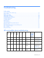
Troubleshooting .......................................................................................................................... 38
LED and audible alarm troubleshooting ...................................................................................................... 38
Battery condition ..................................................................................................................................... 39
Bypass is out of range.............................................................................................................................. 39
General alarm condition .......................................................................................................................... 40
Input voltage is out of range ..................................................................................................................... 40
Insufficient warning of low batteries ........................................................................................................... 40
Internal UPS fault condition....................................................................................................................... 40
Low battery shutdowns ............................................................................................................................. 41
Overload condition ................................................................................................................................. 41
REPO condition....................................................................................................................................... 41
Site wiring condition................................................................................................................................ 41
UPS does not provide the expected backup time ......................................................................................... 41
UPS does not start ................................................................................................................................... 42
UPS frequently switches between utility and battery power............................................................................ 42
UPS is in Auto-Bypass mode...................................................................................................................... 42
UPS is on battery..................................................................................................................................... 42
Utility power condition ............................................................................................................................. 42
Specifications ............................................................................................................................. 43
UPS physical specifications....................................................................................................................... 43
ERM physical specifications ...................................................................................................................... 43
UPS input specifications ........................................................................................................................... 43
UPS output specifications.......................................................................................................................... 44
Power protection specifications ....................................................................................................... 44
Voltage specifications .................................................................................................................... 44
Output tolerance specifications........................................................................................................ 45
Output feature specifications ........................................................................................................... 45
Battery specifications ............................................................................................................................... 45
Battery runtime for NA/JPN model ............................................................................................................ 45
Battery runtime for INTL model .................................................................................................................. 45
Environmental specifications ..................................................................................................................... 46
REPO port specifications .......................................................................................................................... 46
Spares....................................................................................................................................... 47
Ordering spares...................................................................................................................................... 47
UPS spare parts list.................................................................................................................................. 47
Hardware options ................................................................................................................................... 48
Technical support........................................................................................................................ 49
Contents
4
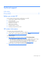
Before you contact HP.............................................................................................................................. 49
HP contact information ............................................................................................................................. 49
Warranty information.................................................................................................................. 50
Limited warranty ..................................................................................................................................... 50
$250,000 Computer Load Protection Guarantee......................................................................................... 50
Pre-Failure Battery Warranty ..................................................................................................................... 50
Regulatory compliance notices ..................................................................................................... 52
Regulatory compliance identification numbers ............................................................................................. 52
Federal Communications Commission notice............................................................................................... 52
FCC rating label............................................................................................................................ 52
Class A equipment......................................................................................................................... 53
Class B equipment ......................................................................................................................... 53
Declaration of conformity for products marked with the FCC logo, United States only....................................... 53
Modifications.......................................................................................................................................... 54
Cables ................................................................................................................................................... 54
Canadian notice (Avis Canadien).............................................................................................................. 54
European Union regulatory notice ............................................................................................................. 54
Disposal of waste equipment by users in private households in the European Union ......................................... 55
Japanese notice ...................................................................................................................................... 55
BSMI notice ............................................................................................................................................ 55
Battery replacement notice........................................................................................................................ 55
Taiwan battery recycling notice................................................................................................................. 56
Power cord statement for Japan................................................................................................................. 56
Electrostatic discharge ................................................................................................................. 57
Preventing electrostatic discharge .............................................................................................................. 57
Grounding methods to prevent electrostatic discharge .................................................................................. 57
Acronyms and abbreviations........................................................................................................ 58
Index......................................................................................................................................... 59
Contents
5
Component identification
In this section
UPS R5500 overview................................................................................................................................ 6
UPS front panel ........................................................................................................................................ 6
UPS front panel controls ............................................................................................................................ 7
UPS front panel LED indicators ................................................................................................................... 8
UPS rear panel ........................................................................................................................................ 9
ERM rear panel...................................................................................................................................... 10
UPS R5500 overview
The HP UPS R5500 features a 3U rack-mount design and offers power protection for loads up to 5000
VA/4500 W (NA/JPN) or 6000 VA/5400 W (INTL). The modular design includes two hot-swappable
battery modules and one hot-swappable electronics module, allowing for reduced downtime and ease of
replacement. The UPS contains an enhanced front-panel display, two independently controlled load
segments, and a communications port for data exchange with a host computer. Supported features
include REPO circuitry, power management software, and various hardware options.
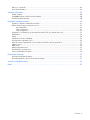
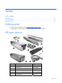
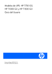
UPS front panel
Item
Description
1
Battery compartment
2
Control buttons
3
LED display
4
Electronics compartment
Component identification 6
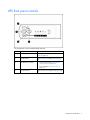
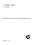
UPS front panel controls
The front panel is shown with the bezel removed.
Item
Description
Function
1
On button
Powers up the UPS ("Starting power to the
load" on page 23)
2
Standby button
Places the UPS in Standby mode (on page
26)
3
Test/Alarm Reset button
•
Silences UPS alarms ("Silencing an
audible alarm" on page 28)
•
Tests the LEDs ("Testing the LEDs" on
page 28)
4
Configure button
Places the UPS in Configure mode (on page
27)
Component identification 7
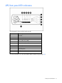
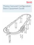
UPS front panel LED indicators
The front panel is shown with the bezel removed.
Item
LED description
1
Overload
2
76% to 100% load
3
51% to 75% load (2 ERMs)
4
26% to 50% load (1 ERM)
5
0% to 25% load (0 ERMs)
6
General Alarm
7
On Battery
8
Battery Fault
9
Site Wiring Fault
10
Utility
11
Configure Mode On
For more information, see "LED and audible alarm troubleshooting (on page 38)" .
Component identification 8
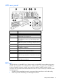
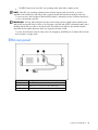
UPS rear panel
Item
Description
1
REPO port
2
Ground bonding screw
3
Communications port/option slot
4
Load segment 1 circuit breaker (controls the C19 and
C13 receptacles, but does not control the large output
receptacle)
5
Load segment 1 (two IEC-320-C19 receptacles, two IEC320-C13 receptacles, and one large output receptacle)
6
Load segment 2 circuit breaker
7
Load segment 2 (two IEC-320-C19 receptacles and two
IEC-320-C13 receptacles)
8
Battery circuit breaker
9
Cord retention clip attachment locations
10
ERM connector
11
Large output NEMA L6-30R receptacle (NA/JPN) or IEC309-32A receptacle (INTL) associated with load segment
1
12
Input power line cord with NEMA L6-30 plug (NA/JPN)
or IEC-309-32A plug (INTL)
REPO port
The UPS includes an isolated REPO port. When properly wired, the REPO feature enables the power at
the UPS output receptacles to be switched off from a remote location. To use this feature, the REPO port
must be connected to a remote, normally open switch (not supplied). The REPO switch is used in
conjunction with a main disconnect device that removes the AC source from the input of the UPS. When
the switch is closed:
•
The REPO feature immediately powers down protected devices and does not utilize the orderly
shutdown procedure initiated by power management software.
Component identification 9
•
The REPO feature shuts down UPS units operating under either utility or battery power.
NOTE: If the UPS was operating on battery power when the remote switch was closed, no power is
available to the load devices until utility power is restored and the UPS has been manually powered up.
To restore power to the load devices after the REPO feature is activated, press the On button after the AC
source is reconnected to the UPS.
IMPORTANT: Pressing and holding the On button without utility present normally initiates a battery start
and the UPS assumes the load. However, if the On button is pressed and a REPO is detected, battery start is
inhibited and the UPS is not able to assume the load. The electronics module fan spins and the General
Alarm LED and an audible alarm are active as long as the On button is held.
To power down the entire network in the event of an emergency, the REPO ports of multiple UPS units can
be connected to a single switch.
ERM rear panel
Item
Description
1
Circuit breaker
2
ERM input connector (from another ERM output)
3
ERM output connector (to the UPS or another ERM)
Component identification 10
Installation
In this section
Precautions............................................................................................................................................ 11
Preparing to install the hardware ............................................................................................................. 11
Installing the mounting rails ..................................................................................................................... 13
Preparing the rails for integrated shipping................................................................................................. 15
Installing the UPS ................................................................................................................................... 15
Installing the ERM................................................................................................................................... 23
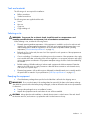
Precautions
Save these instructions. This document contains important safety instructions that should be followed
during installation, operation, and maintenance of the UPS and batteries.
WARNING: A risk of personal injury from electric shock and hazardous energy levels
exists. The installation of options and routine maintenance and service of this product
must be performed by individuals who are knowledgeable about the procedures,
precautions, and hazards associated with AC power products.
This symbol indicates that the UPS exceeds the recommended weight for one
individual to handle safely.
68 kg
150 lb
WARNING: To reduce the risk of personal injury or damage to the equipment,
observe local occupational health and safety requirements and guidelines for manual
material handling.
This symbol indicates that the ERM exceeds the recommended weight for one
individual to handle safely.
75 kg
167 lb
WARNING: To reduce the risk of personal injury or damage to the equipment,
observe local occupational health and safety requirements and guidelines for manual
material handling.
WARNING: To prevent personal injury from earth conductor leakage current:
• Do not operate the UPS while disconnected from the utility power source.
• Disconnect load devices before disconnecting the UPS from the utility power source.
Preparing to install the hardware
Before installing the hardware:
1.
Be sure the necessary tools and materials (on page 12) are available.
2.
Select an installation site ("Selecting a site" on page 12).
3.
Prepare the equipment ("Readying the equipment" on page 12) for installation in the rack.
Installation 11
Tools and materials
The following tools are required for installation:
•
Phillips screwdriver
•
10-mm hex-nut driver
The following items are supplied with the rack:
•
Screws
•
Hex nuts
•
Cage nuts
•
Cage nut-fitting tool
Selecting a site
WARNING: To prevent fire or electric shock, install the unit in a temperature- and
humidity-controlled indoor environment, free of conductive contaminants.
When selecting a site, consider the following factors:
•
Elevated operating ambient temperature—If the equipment is installed in a closed or multi-unit rack
assembly, the operating ambient temperature of the rack environment might be greater than room
ambient temperature. Install the equipment in an environment compatible with the operating
temperature ("Environmental specifications" on page 46).
•
Reduced air flow—In the rack, the rate of air flow required for safe operation of the equipment must
not be compromised.
•
Circuit overloading—Consideration should be given to the connection of the equipment to the supply
circuit and the effect that overloading of the circuits might have on overcurrent protection and supply
wiring. Appropriate consideration of equipment nameplate ratings should be used when addressing
this concern.
•
Reliable earthing—Reliable earthing of rack-mounted equipment should be maintained. Particular
attention should be given to supply connections other than direct connections to the branch circuit,
such as the use of power strips.
•
Electrical requirements—All models require a dedicated (unshared) branch circuit, suitably rated for
the specific UPS as stated in "Input specifications ("UPS input specifications" on page 43)" .
Readying the equipment
1.
Check the battery recharge date specified on the label that is affixed to the shipping carton.
IMPORTANT: Do not use the battery if the recharge date has passed. If the date on the battery recharge
date label has passed without the battery being recharged, contact an HP authorized service representative
for directions.
2.
Transport the packaged unit to its installation location.
3.
Unpack the equipment near the rack where the unit will be assembled.
CAUTION: Always plan the rack installation so that the heaviest item is on the bottom of the rack. Install
the heaviest item first, and continue to populate the rack from the bottom to the top.
Installation 12
Installing the mounting rails
WARNING: To reduce the risk of personal injury or damage to the equipment, be sure
that:
• The leveling feet are extended to the floor.
• The full weight of the rack rests on the leveling feet.
• The stabilizing feet are attached to the rack if it is a single-rack installation.
• The racks are coupled together in multiple-rack installations.
• Only one component is extended at a time. A rack may become unstable if more than
one component is extended for any reason.
NOTE: Mounting hardware for square- and round-holed racks is included in the UPS kit.
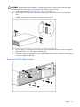
1.
Loosen the hex nuts, and extend the brackets to the desired length.
2.
Insert screws through the rack into the mounting rail and the front of each mounting bracket.
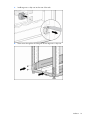
Installation 13
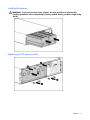
3.
Install cage nuts or clip nuts into the rear of the rack.
4.
Insert screws through the mounting rail into the cage nuts or clip nuts.
Installation 14
5.
Tighten the hex nuts.
Preparing the rails for integrated shipping
If the unit is to be shipped in an HP 9000 or 10000 series rack:
1.
Remove the hex nuts, flat washers, and lock washers from the mounting rail.
2.
Install the rail reinforcement plates and tighten using the hex nuts with captive washers included in
the kit, instead of the nuts included with the rail.
3.
Install the rear mounting brackets using hex nuts. Wait until the unit is installed and the brackets are
adjusted before tightening the nuts.
Installing the UPS
Before installing the UPS, review and observe all warnings in "Precautions (on page 11)."
WARNING: Uneven mechanical loading in the rack may cause a hazardous condition.
Installation 15
CAUTION: Always plan the rack installation so that the heaviest item is on the bottom of the rack. Install
the heaviest item first, and continue to populate the rack from the bottom to the top.
1.
Install the mounting rails ("Installing the mounting rails" on page 13).
2.
With one person on each side of the carton, lift the chassis and lower it to the floor in front of the
rack.
3.
Install the mounting ears on the chassis using the screws provided.
4.
With one person on each side, lift the chassis to rail level and slide the chassis on the mounting rails.
5.
Attach the chassis to the rack using the supplied screws.
6.
If using the rear mounting brackets, be sure that the bracket tabs are fully inserted into the rear panel
cutouts, then tighten the brackets.
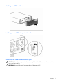
Removing the UPS battery bracket
Installation 16
Installing the batteries
WARNING: To prevent personal injury, prepare the area and observe all materialshandling procedures when transporting a battery module. Battery modules weigh 20 kg
(44 lb).
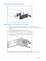
Replacing the UPS battery bracket
Installation 17
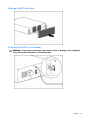
Attaching the UPS front bezel
Switching on the UPS battery circuit breaker
Connecting the serial communications port
CAUTION: Use only the computer interface cable supplied with the UPS to connect the communications
port to the host computer.
CAUTION: Using a USB to serial converter cable will damage the UPS.
Installation 18
IMPORTANT: Power management software requires the communications port to be appropriately cabled
to the host computer.
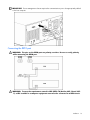
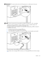
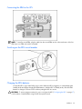
Connecting the REPO port
WARNING: The pins on the REPO port are polarity sensitive. Be sure to verify polarity
while connecting the REPO port.
WARNING: To meet the requirements stated in NEC (NFPA 70) Articles 645-10 and 64511, a UPS installed in a computer equipment room must be connected to a REPO circuit.
Installation 19
IMPORTANT: The remote switch must be in the Off (open) position to enable power to the output
receptacles.
NOTE: Wire the connector block using stranded, nonshielded wire (AWG #22 - #18, or equivalent).
Separate wire pairs are attached to a single, normally-open contact in a parallel connection. HP
recommends using different colors for the positive and negative wires.
If a connector becomes disconnected and is reconnected with reversed polarity, a REPO is initiated. To
avoid REPO port disconnect:
•
Minimize wire strain while connecting the REPO port.
•
Avoid allowing the wires to hang in the rear of the UPS.
•
Use tie wraps and tie wrap blocks to secure the wires tightly to the rack and the rear of the UPS.
For more information about the REPO port, see "REPO port (on page 9)" .
For information about verifying the REPO connection, see "Verifying the REPO port connection (on page
29)" .
Installation 20
Connecting the ground bonding cable
The ground bonding screw is provided as an attachment point for conductors. Use a ground bonding
cable if the rack contains any conductors for the purpose of functional grounding or bonding of
ungrounded metal parts.
The ground bonding cable is not included.
Connecting the UPS to utility power
WARNING: To prevent injury from electric shock or damage to the equipment:
• Plug the input line cord into a grounded (earthed) electrical outlet that is installed
near the equipment and is easily accessible.
• Do not disable the grounding plug on the input line cord. The grounding plug is an
important safety feature.
• Do not use extension cords.
Connect the UPS to a grounded utility power outlet. When the UPS is plugged in, it automatically enters
Standby mode and begins charging the batteries.
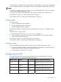
Connecting devices to the UPS
CAUTION: Do not plug laser printers into the UPS output receptacles. The instantaneous current drawn by
this type of printer can overload the UPS.
Before connecting devices:
•
Verify that the UPS will not overload by checking that the ratings of the devices do not exceed the
UPS capacity.
•
Evenly distribute connected devices to both circuit breakers. See "UPS output specifications (on page
44)" for the maximum current rating for each receptacle.
After verifying that the UPS will not overload:
1.
Turn on the circuit breakers for load segments 1 and 2.
NOTE: The circuit breaker for load segment 1 protects the C19 and C13 outlets but not the large output
receptacle.
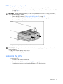
Installation 21
2.
Connect the device power cords to the appropriate output receptacles on the rear panel of the UPS.
To provide additional receptacles:
•
Plug a PDU or other device into the high current, large output receptacle. The large output receptacle
is part of load segment 1 and can be turned off and on using power management software (on page
30).
•
Plug an extension bar into any IEC-320-C19 receptacle to yield eight additional IEC-320-C13
receptacles.
Connecting the UPS cord retention clips
Charging the UPS batteries
With the UPS in Standby mode, allow the batteries to charge before putting the UPS into service.
IMPORTANT: Charge the batteries for at least 24 hours before supplying backup power to devices. The
batteries charge to:
Installation 22
•
•
80 percent of their capacity within 3 hours
100 percent of their capacity within 48 hours
Starting power to the load
Start power to the load by placing the UPS in Operate mode (on page 26).
IMPORTANT: AC power must be available the first time the UPS is started.
Installing the ERM
Before installing the ERM, review and observe all warnings in "Precautions (on page 11)."
WARNING: Uneven mechanical loading in the rack may cause a hazardous condition.
CAUTION: Always plan the rack installation so that the heaviest item is on the bottom of the rack. Install
the heaviest item first, and continue to populate the rack from the bottom to the top.
1.
Install the mounting rails ("Installing the mounting rails" on page 13).
2.
With one person on each side of the carton, lift the chassis and lower it to the floor in front of the
rack.
3.
Install the mounting ears on the chassis using the screws provided.
4.
With one person on each side, lift the chassis to rail level and slide the chassis on the mounting rails.
5.
Attach the chassis to the rack using the supplied screws.
6.
If using the rear mounting brackets, be sure that the bracket tabs are fully inserted into the rear panel
cutouts, then tighten the brackets.
Installation 23
Attaching the ERM front bezel
Switching off the ERM circuit breaker
WARNING: To prevent personal injury from electric shock or damage to the equipment,
verify that the circuit breaker is in the Off position.
Installation 24
Connecting the ERM to the UPS
NOTE: To install a second ERM, plug the cable from the second ERM into the socket at the rear of the first
ERM. Up to two ERM units can be connected.
Switching on the ERM circuit breaker
Charging the ERM batteries
Connect the UPS to a grounded utility power outlet. When the UPS is plugged in, it automatically enters
Standby mode and begins charging the ERM batteries. With the UPS in Standby mode, allow the ERM
batteries to charge for at least 24 hours before putting the UPS into service.
CAUTION: To ensure maximum runtime, be sure to configure the UPS ("Configuring the UPS" on page 27)
for the number of installed ERMs using the UPS front panel controls.
Installation 25
UPS operations
In this section
Modes of operation ................................................................................................................................ 26
Configuring the UPS ............................................................................................................................... 27
Testing the LEDs ..................................................................................................................................... 28
Silencing an audible alarm...................................................................................................................... 28
Verifying the REPO port connection .......................................................................................................... 29
Powering down the UPS.......................................................................................................................... 29
Modes of operation
The UPS has four modes of operation:
•
Standby mode (on page 26)
•
Operate mode (on page 26)
•
Configure mode (on page 27)
•
Auto-Bypass mode (on page 27)
Standby mode
In Standby mode:
•
No power is available at the UPS output receptacles.
•
The UPS charges the batteries as necessary.
The UPS can be placed in Standby mode when the UPS is in Operate mode (on page 26).
To place the UPS in Standby mode, press and hold the Standby button until the audible alarm sounds and
the Utility LED flashes. Power to the load ceases.
IMPORTANT: While in Standby mode, the UPS maintains the charge on the batteries, but no power is
available at the output receptacles. The UPS remains in Standby mode until an alternate mode is selected or
until utility power is removed.
For the location of buttons, see "UPS front panel controls (on page 7)."
For the location of LEDs, see "UPS front panel LED indicators (on page 8)."
Operate mode
In Operate mode:
•
Power is available at the UPS receptacles.
•
The UPS charges the batteries as necessary.
The UPS can be placed in Operate mode if either of the following conditions apply:
•
The UPS is powered up and in Standby mode (on page 26).
•
The UPS is powered down and no utility power is available.
UPS operations 26
To place the UPS in Operate mode, press the On button. The Utility LED turns solid green, indicating that
power is available at the UPS output receptacles. The UPS acknowledges compliance with a short beep.
NOTE:
• If the UPS is using battery power (no utility power is present and the Utility LED is red), press and hold
the On button until the audible alarm sounds.
• If the UPS is off (no LEDs are illuminated), press the On button to start the UPS on battery power.
For the location of buttons, see "UPS front panel controls (on page 7)."
For the location of LEDs, see "UPS front panel LED indicators (on page 8)."
Configure mode
In Configure mode:
•
Power is available at the UPS receptacles.
•
The UPS charges the batteries as necessary.
•
The UPS configuration can be updated.
The UPS can be placed in Configure mode while in Operate mode (on page 26) or Standby mode (on
page 26).
To place the UPS in Configure mode:
1.
Remove the front bezel ("Removing the UPS front bezel" on page 31).
2.
Press and hold the Configure button until the front panel LEDs flash in unison and the Configure
Mode On LED illuminates solid green.
For the location of buttons, see "UPS front panel controls (on page 7)."
For the location of LEDs, see "UPS front panel LED indicators (on page 8)."
Auto-Bypass mode
The UPS automatically enters Auto-Bypass mode when either of the following conditions occurs:
•
The power from the UPS reaches a percentage greater than 110 percent for more than 10 cycles or
between 103 percent and 110 percent for more than 2 minutes.
•
The UPS electronics module fails or is removed.
Configuring the UPS
In Configure mode, the LED front panel display changes function to enable modification of the UPS
parameters. Each LED is associated with a different parameter.
Available settings
Parameter
Associated LED
Explanation (when LED is illuminated)
Nominal Voltage
Setting
200/208 Nom
General Alarm
(red)
Nominal utility voltage level is set to
200/208 VAC (factory default for 326529D71)
220 Nom
On Battery (red)
Nominal utility voltage level is set to 220
VAC
230 Nom
Battery Fault
(red)
Nominal utility voltage level is set to 230
VAC (factory default for 326529-B31)
240 Nom
Site Wiring Fault Nominal utility voltage level is set to 240
(red)
VAC
UPS operations 27
Available settings
Parameter
Associated LED
Explanation (when LED is illuminated)
Wiring Fault Setting Wiring Fault
Utility (green)
Audible alarm sounds when ground is
missing or line and neutral connections are
reversed
ERM Setting
0 ERMs
0% to 25% load UPS is configured for no attached ERMs
(green)
(factory default)
1 ERM
26% to 50%
load (green)
UPS is configured for 1 attached ERM
2 ERMs
51% to 75%
load (green)
UPS is configured for 2 attached ERMs
To change the UPS configuration parameters:
1.
Place the UPS in Configure mode (on page 27).
The LEDs associated with the currently configured parameters illuminate. A flashing green cursor
indicates where you are in the configuration process as you scroll through the available settings.
2.
To change the nominal voltage, press the On button to advance the cursor to the LED associated with
the appropriate nominal voltage parameter. The selected voltage configuration LED flashes.
3.
Press the Standby button to select the nominal voltage configuration. The LED associated with the old
input voltage parameter turns off, and the LED associated with the new input voltage parameter
illuminates solid green.
NOTE: Only one nominal utility voltage can be configured. When setting voltage configuration parameters,
selecting an On value for any one parameter automatically sets the other possibilities to Off.
4.
To enable the Wiring Fault parameter, press the On button to advance the cursor to the Utility LED,
then press the Standby button. The LED illuminates solid green. This parameter is disabled by default,
and should only be enabled for line-to-neutral connections. Enabling this feature for line-to-line power
sources causes a false alarm.
5.
To configure the UPS for the number of connected ERMs, press the On button to advance the cursor
to the load LED associated with the number of ERMs attached to the UPS.
6.
Press the Standby button to select the appropriate ERM configuration. The associated LED illuminates
solid green.
7.
To save the configuration settings and exit Configure mode, press the Test/Alarm Reset button.
NOTE: Configure mode times out after 2 minutes. If the Test/Alarm Reset button has not been pressed, any
new selections are not saved.
Testing the LEDs
To test the LEDs, press and hold the Test/Alarm Reset button for 3 seconds.
Silencing an audible alarm
To silence an alarm, press the Test/Alarm Reset button ("UPS front panel controls" on page 7).
IMPORTANT:
UPS operations 28
•
•
Although the audible alarm silences, the condition that caused the alarm to sound may still exist.
If a utility power failure caused the alarm (the Utility LED or the General Alarm LED illuminates red), the
alarm silences after power is restored.
For information about audible alarm conditions, see "LED and audible alarm troubleshooting (on page
38)."
Verifying the REPO port connection
NOTE: While testing, operate connected equipment in a safe test mode so the effects do not disrupt critical
operations.
After connecting the REPO port (on page 19):
1.
Initiate a REPO by closing the REPO contact.
The General Alarm LED and Utility LED ("UPS front panel LED indicators" on page 8) flash.
CAUTION: If the polarity is reversed while connecting the REPO port, the UPS powers up normally.
2.
Verify proper connection of the REPO port:
a. Power up the UPS ("Starting power to the load" on page 23).
b. Disconnect the REPO port.
c. Reconnect the REPO port.
If the polarity is correct, the REPO connectors can be disconnected, and then reconnected,
without initiating a REPO.
d. Verify that the UPS remains in Operate mode (on page 26).
e. If a REPO is initiated, the polarity is reversed. Check and correct the connections.
Powering down the UPS
1.
Shut down all load devices.
2.
Press the Standby button to take the UPS out of Operate mode. Power to the load receptacles
ceases.
3.
Disconnect the UPS from utility power.
4.
Wait at least 60 seconds for the UPS internal circuitry to discharge.
UPS operations 29
Power management
In this section
Power management software................................................................................................................... 30
Power management software
HP Power Manager software ensures maximum power reliability of computer systems through
comprehensive control of UPSs. The easy-to-use browser interface enables novice users to configure and
manage power protection settings. To download the latest version of HP Power Manager software, see
the HP website (http://www.hp.com/go/rackandpower).
NOTE: To install and configure the software, see the software user guide. The software user guide is
available for download from the HP website (http://www.hp.com/go/rackandpower).
HP Power Manager:
•
Does not require complex management systems, which simplifies deployment, configuration, and
management of UPS-protected environments.
•
Manages a graceful shutdown of attached devices during utility power failures.
•
Prioritizes the timing of attached load device shutdowns.
•
Shuts down and reboots any UPS and attached load devices based on a user-specified schedule.
•
Customizes alert generation with modifiable dialog boxes, command execution, and email and
broadcast messages.
•
Monitors the status of the UPS and reports alarms.
•
Displays a power log for analysis.
•
Manages independent UPS load segments to provide separate power control of attached load
devices.
•
Delays reboot by load segment after a power outage to sequence the startup of system components.
Power management 30
Maintenance
In this section
Removing the UPS front bezel .................................................................................................................. 31
Removing the ERM front bezel ................................................................................................................. 32
Replacing the UPS electronics module....................................................................................................... 32
Replacing the UPS option card................................................................................................................. 33
Replacing the batteries............................................................................................................................ 34
Replacing the UPS .................................................................................................................................. 35
Replacing the ERM ................................................................................................................................. 36
Updating the UPS firmware ..................................................................................................................... 37
Removing the UPS front bezel
Maintenance 31
Removing the ERM front bezel
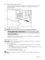
Replacing the UPS electronics module
This component is hot-swappable and can be replaced without powering down the UPS.
1.
(optional) To replace the component with the UPS powered down, refer to "Powering down the UPS
(on page 29)."
2.
Disconnect the communications cable from the option card.
3.
Remove the option card ("Replacing the UPS option card" on page 33).
4.
Remove the UPS front bezel ("Removing the UPS front bezel" on page 31).
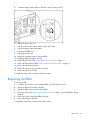
5.
Remove the screw securing the electronics module and slide the module out.
6.
Replace the electronics module. Be sure the electronics module is firmly seated in the connector.
Maintenance 32
7.
Replace the screw.
8.
Replace the option card.
9.
Reconnect the external cable to the card.
10. Verify that the UPS is configured to the proper voltage and number of attached ERMs. See
"Configuring the UPS (on page 27)."
11. Replace the front bezel.
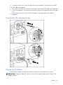
Replacing the UPS option card
This component is hot-swappable and can be replaced without powering down the UPS.
1.
(optional) To replace the component with the UPS powered down, refer to "Powering down the UPS
(on page 29)."
2.
Disconnect the communications cable from the option card.
3.
Remove the two screws securing the option card and slide the card out.
Maintenance 33
To replace the component, reverse the removal procedure.
NOTE: Replacing the option card might require power management software to be restarted or
reconfigured.
Replacing the batteries
To replace the batteries:
1.
Read and observe the requirements in "Important battery safety information (on page 34)" and
"Battery care and storage guidelines (on page 34)."
2.
Follow the instructions in "UPS battery replacement procedure (on page 35)."
Important battery safety information
WARNING: The unit contains sealed lead-acid battery modules. To prevent fire or
chemical burns:
• Do not attempt to recharge batteries after removal from the unit.
• Do not disassemble, crush, or puncture the batteries.
• Do not short the external contacts of the batteries.
• Do not immerse the batteries in water.
• Do not expose to temperatures higher than 60°C (140°F).
WARNING: To prevent personal injury from hazardous energy:
• Remove watches, rings, or other metal objects.
• Use tools with insulated handles.
• Do not place tools or metal parts on top of batteries.
WARNING: To prevent personal injury, prepare the area and observe all materialshandling procedures when transporting a battery module. Battery modules weigh 20 kg
(44 lb).
NOTE: Replace all battery modules at the same time.
Battery care and storage guidelines
•
Minimize the amount of time the UPS uses battery power by matching the UPS configuration with the
utility voltage. Refer to "Configuring the UPS (on page 27)."
•
Keep the area around the UPS clean and dust-free. If the environment is very dusty, clean the outside
of the UPS regularly with a vacuum cleaner.
•
Maintain the ambient temperature at 25°C (77°F).
•
If storing a UPS for an extended period, recharge the batteries every 6 months:
CAUTION: Because of the short shelf life of the batteries, avoid storing a battery spare as a backup. Do
not maintain an inventory of spare batteries on site unless a procedure to keep these batteries charged while
in storage is implemented.
a. Connect the UPS to utility power.
b. Allow the UPS to remain in Standby mode.
c. Allow the UPS to charge the batteries for at least 24 hours.
d. Update the battery recharge date label.
Maintenance 34
UPS battery replacement procedure
This component is hot-swappable and can be replaced without powering down the UPS.
1.
(optional) To replace the component with the UPS powered down, refer to "Powering down the UPS
(on page 29)."
CAUTION: When hot-swapping batteries, the UPS is not protected in the event of a utility power failure,
unless at least one ERM is installed.
2.
Remove the UPS front bezel ("Removing the UPS front bezel" on page 31).
3.
Remove the UPS battery bracket ("Removing the UPS battery bracket" on page 16).
4.
Remove the UPS battery modules.
To replace the component, reverse the removal procedure.
IMPORTANT: Charge the batteries for at least 24 hours before supplying backup power to devices. The
batteries charge to:
• 80 percent of their capacity within 3 hours
• 100 percent of their capacity within 48 hours
Replacing the UPS
To remove the UPS:
1.
Power down all attached load devices.
2.
Power down the UPS ("Powering down the UPS" on page 29).
3.
Switch the circuit breaker for any attached ERMs to the Off (down) position.
Maintenance 35
4.
Switch the battery circuit breaker for the UPS to the Off (down) position.
5.
Unplug the UPS power cord.
6.
Disconnect the communications cable from the option card.
7.
Disconnect the ground bonding cable.
8.
Disconnect the REPO port.
9.
Unplug the load devices.
10. Unplug all connected extension bars and PDUs.
11. Unplug the ERM connected to the UPS.
12. Remove the UPS front bezel ("Removing the UPS front bezel" on page 31).
13. Remove the UPS battery bracket ("Removing the UPS battery bracket" on page 16).
14. Remove the UPS battery modules.
15. Remove the screws securing the UPS to the rack.
16. Remove the UPS from the rack.
To replace the component, reverse the removal procedure.
Replacing the ERM
To remove the ERM:
1.
Switch the circuit breaker for any attached ERMs to the Off (down) position.
2.
Unplug the ERM from the back of the UPS.
3.
Unplug the ERM from a second connected ERM.
4.
Remove the front bezel ("Removing the ERM front bezel" on page 32) on the ERM that is being
replaced.
5.
Remove the screws securing the ERM to the rack.
6.
Remove the ERM from the rack.
To replace the component, reverse the removal procedure.
Maintenance 36
Updating the UPS firmware
CAUTION: Using a USB to serial converter cable will damage the UPS.
To update the UPS firmware, see the HP website (http://www.hp.com/go/rackandpower).
Maintenance 37
Troubleshooting
In this section
LED and audible alarm troubleshooting..................................................................................................... 38
Battery condition .................................................................................................................................... 39
Bypass is out of range ............................................................................................................................ 39
General alarm condition ......................................................................................................................... 40
Input voltage is out of range .................................................................................................................... 40
Insufficient warning of low batteries.......................................................................................................... 40
Internal UPS fault condition...................................................................................................................... 40
Low battery shutdowns............................................................................................................................ 41
Overload condition ................................................................................................................................ 41
REPO condition...................................................................................................................................... 41
Site wiring condition............................................................................................................................... 41
UPS does not provide the expected backup time ........................................................................................ 41
UPS does not start .................................................................................................................................. 42
UPS frequently switches between utility and battery power .......................................................................... 42
UPS is in Auto-Bypass mode .................................................................................................................... 42
UPS is on battery.................................................................................................................................... 42
Utility power condition ............................................................................................................................ 42
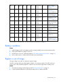
LED and audible alarm troubleshooting
General
Alarm
LED
On
Battery
LED
Battery
Fault
LED
Site
Wiring
Fault
LED
Utility
LED
Overload
LED
Audible alarm
Can alarm
be silenced
("Silencing
an audible
alarm" on
page 28)?
Condition
Off
Off
Off
Off
Green
Off
No audible
alarm
N/A
UPS is in Operate
mode (on page 26)
Off
Off
Off
Off
Flashing Off
green
No audible
alarm
N/A
UPS is in Standby
mode (on page 26)
Off
Off
Off
Off
Red
Off
On—1 beep
every 5
seconds
Yes
UPS is in Auto-Bypass
mode (on page 27)
Flashing
red
Off
Off
Off
Red
Off
On—1 beep
every 5
seconds
Yes
General alarm
condition—UPS is in
Auto-Bypass mode
("General alarm
condition" on page 40)
Off
Off
Off
Off
Flashing Off
red
On—1 beep
every 5
seconds
Yes
Bypass is out of range
(on page 39)
Troubleshooting 38
Flashing Off
red
Off
Off
On—1 beep
every 5
seconds
Yes
Battery test failure
("Battery condition" on
page 39)
Off
Off
Off
On—1 beep
every 5
seconds
No
Low battery—No utility
power ("UPS is on
battery" on page 42)
Off
Flashing Off
red
Off
Off
On—1 beep
every 5
seconds
Yes
Batteries are
disconnected ("Battery
condition" on page 39)
Off
Red
Off
Off
Off
Off
On—1 beep
every 5
seconds
Yes
On battery—No utility
power ("UPS is on
battery" on page 42)
Off
Flashing Off
red
Off
Flashing Off
red
On—1 beep
every 5
seconds
Yes
On battery—Input
voltage is out of range
(on page 40)
Flashing
red
Flashing Flashing Flashing Flashing Flashing
red
red
red
red
red
On—
Continuous
No
Internal UPS fault
condition (on page 40)
Red
Off
Off
Off
Off
Off
On—
Continuous
Yes
Battery condition (on
page 39)
Flashing
red
Off
Off
Off
Flashing Off
green
On—
Continuous
Yes
REPO condition (on
page 41)
Off
Off
Off
Red
Off
Off
On—1 beep
every 5
seconds
Yes
Site wiring condition
(on page 41)
Flashing
red
Off
Off
Off
Off
Red
On—
Continuous
Yes
UPS power capacity is
exceeded ("Overload
condition" on page 41)
Off
Off
Off
Flashing Off
red
Off
For the location of individual LEDs, see "UPS front panel LED indicators (on page 8)."
Battery condition
Action:
1.
Install the battery module. If the battery module is already installed, remove and reinsert the module.
2.
Allow the UPS batteries to charge for 48 hours.
3.
If the LED does not turn off, replace the batteries ("UPS battery replacement procedure" on page 35).
4.
If the condition persists, contact an HP authorized service representative.
Bypass is out of range
The input voltage is not within ±12 percent of nominal voltage.
The UPS is receiving utility power that might be unstable or in brownout conditions. The UPS continues to
supply power to the connected equipment. If conditions worsen, the UPS might switch to battery power.
Action:
1.
Check the input voltage and reconfigure the UPS ("Configuring the UPS" on page 27).
2.
Contact a qualified electrician to verify that the utility power is suitable for the UPS.
Troubleshooting 39
General alarm condition
Action:
1.
If power management software is being used, check the log files to obtain specific error information
to help identify the problem.
For more information about the causes of a general alarm condition, see the HP Power Manager
user guide available for download from the HP website (http://www.hp.com/go/rackandpower).
2.
Check the batteries:
a. Allow the UPS batteries to charge for 48 hours.
b. If the Battery Fault LED is red, replace the batteries ("UPS battery replacement procedure" on
page 35).
3.
Reduce the load:
a. Power down the UPS ("Powering down the UPS" on page 29).
b. Remove one or more load devices to reduce the power requirements.
c. Wait at least 5 seconds and restart the UPS.
d. If the condition persists, verify that the load devices are not defective.
4.
Allow the UPS to cool:
a. Power down the UPS ("Powering down the UPS" on page 29).
b. Clear vents and remove any heat sources.
c. Verify that the airflow around the UPS is not restricted.
5.
Wait at least 5 minutes and restart the UPS.
6.
If the condition persists, contact an HP authorized service representative.
Input voltage is out of range
Action:
1.
Check the input voltage and reconfigure the UPS ("Configuring the UPS" on page 27).
2.
Contact a qualified electrician to verify that the utility power is suitable for the UPS.
Insufficient warning of low batteries
Action:
1.
Verify that the power management software is not delaying the shutdown of attached servers when
the UPS is in a low battery condition.
2.
Allow the UPS batteries to charge for 48 hours.
3.
If the Battery Fault LED is red, replace the batteries ("UPS battery replacement procedure" on page
35).
Internal UPS fault condition
Action:
1.
Power down the UPS ("Powering down the UPS" on page 29).
2.
If the condition persists, contact an HP authorized service representative.
Troubleshooting 40
Low battery shutdowns
Ungraceful shutdown of attached servers occurs when the UPS is in a low battery condition.
Action:
1.
Verify that the power management software is not delaying the shutdown of attached servers when
the UPS is in a low battery condition.
2.
Allow the UPS batteries to charge for 48 hours.
3.
If the Battery Fault LED is red, replace the batteries ("UPS battery replacement procedure" on page
35).
Overload condition
All the load LEDs are illuminated.
Action:
1.
Power down the UPS ("Powering down the UPS" on page 29).
2.
Remove one or more load devices to reduce the power requirements.
3.
Wait at least 5 seconds and restart the UPS.
4.
If the condition persists, verify that the load devices are not defective.
REPO condition
Action:
•
If the remote switch is closed, then open the switch to enable power to the output receptacles.
•
If the condition occurred while reconnecting a disconnected REPO port, then verify the polarity of the
REPO connector pins.
For more information about REPO ports, see "Connecting the REPO port (on page 19)."
Site wiring condition
Action: Contact a qualified electrician to be sure that:
•
The utility power receptacle is grounded.
•
There is a ground wire in the UPS power cord.
•
The line and neutral wires are not reversed in the wall outlet.
UPS does not provide the expected backup time
Action:
1.
If the Overload LED ("UPS front panel controls" on page 7) is illuminated, remove one or more load
devices to reduce the power requirements.
2.
Allow the UPS batteries to charge for 48 hours.
3.
If the Battery Fault LED is red, replace the batteries ("UPS battery replacement procedure" on page
35).
4.
During extended power outages, save your work, power down the load devices, and then power
down the UPS ("Powering down the UPS" on page 29) to conserve battery power.
Troubleshooting 41
UPS does not start
Action:
1.
Be sure that the power cord is plugged in to a utility power receptacle.
2.
Check the power source at the utility power receptacle.
UPS frequently switches between utility and battery power
Action:
1.
Check the input voltage and reconfigure the UPS ("Configuring the UPS" on page 27).
2.
Contact a qualified electrician to verify that the utility power is suitable for the UPS.
UPS is in Auto-Bypass mode
Action:
1.
If power management software is being used, check the log files to obtain specific error information
to help identify the problem.
For more information about the causes of a general fault condition, see the HP Power Manager user
guide available for download from the HP website (http://www.hp.com/go/rackandpower).
2.
Verify that no blockage of airflow to the front bezel and rear panel exists.
3.
If the LED does not turn off, replace the electronics module. ("Replacing the UPS electronics module"
on page 32)
UPS is on battery
Action: Save files and shut down connected equipment.
Utility power condition
The utility input voltage is outside the operating range.
Action:
1.
Check the input voltage and reconfigure the UPS ("Configuring the UPS" on page 27).
2.
Contact a qualified electrician to verify that the utility power is suitable for the UPS.
Troubleshooting 42
Specifications
In this section
UPS physical specifications...................................................................................................................... 43
ERM physical specifications..................................................................................................................... 43
UPS input specifications .......................................................................................................................... 43
UPS output specifications......................................................................................................................... 44
Battery specifications .............................................................................................................................. 45
Battery runtime for NA/JPN model ........................................................................................................... 45
Battery runtime for INTL model ................................................................................................................. 45
Environmental specifications .................................................................................................................... 46
REPO port specifications ......................................................................................................................... 46
UPS physical specifications
Parameter
Value
Height
13.03 cm (5.13 in)
Depth
66.04 cm (26 in)
Width
44.15 cm (17.38 in)
Weight
68 kg (150 lb)
ERM physical specifications
Parameter
Value
Height
13.03 cm (5.13 in)
Depth
63.83 cm (25.13 in)
Width
44.45 cm (17.50 in)
Weight
75 kg (167 lb)
UPS input specifications
NOTE: An asterisk (*) indicates the default setting.
UPS model
Utility voltage
frequency (Hz)
Available settings utility Dedicated
voltage (VAC)
branch circuit
rating (A)
Line cord
R5500 XR
NA/JPN
50/60
200/208*, 220, 230, 30
240
Nondetachable power
cord with NEMA L6-30
plug
Specifications
43
UPS model
Utility voltage
frequency (Hz)
Available settings utility Dedicated
voltage (VAC)
branch circuit
rating (A)
Line cord
R5500 XR INTL
50/60
200/208, 220, 230*, 32
240
Nondetachable power
cord with 32 A IEC-309
plug
UPS output specifications
UPS model
Load
segment
Circuit
breaker
Output receptacles
Maximum current
R5500 XR NA/JPN
1
15 A¹
2 x IEC-320-C19
15 A per receptacle²
2 x IEC-320-C13
10 A per receptacle
1 x L6-30R
Up to full UPS power rating
2 x IEC-320-C19
15 A per receptacle²
2 x IEC-320-C13
10 A per receptacle
2 x IEC-320-C19
15 A per receptacle²
2 x IEC-320-C13
10 A per receptacle
1 x IEC-309-32A
Up to full UPS power rating
2 x IEC-320-C19
15 A per receptacle²
2 x IEC-320-C13
10 A per receptacle
2
R5500 XR INTL
1
2
15 A¹
15 A¹
15 A¹
¹
NOTE: The circuit breakers protect the C19 and C13 outlets.
²
NOTE: If an extension bar is connected to a C19 receptacle, the maximum current for each C13 receptacle
on the extension bar is 10 A. The total maximum current for the extension bar is 12 A.
Power protection specifications
UPS model
VA
Nominal power
rating (W)
Nominal voltage
setting
R5500 XR NA/JPN
5000
4500
200/208, 220,
230, 240
R5500 XR INTL
6000
5400
220, 230, 240
5000
4500
200/208
Voltage specifications
Configuration setting (VAC)
Available nominal output voltage (VAC)
200/208
204
220
220
230
230
240
240
Specifications
44
Output tolerance specifications
Source of power
Regulation
Utility power (nominal
range)
-10% to +6% of nominal output voltage rating
(within the guidelines of the Computer Business
Equipment Manufacturers Association)
Battery power
±5% of nominal output voltage rating
Output feature specifications
Feature
Specification
Online efficiency
94% nominal input voltage
Voltage wave shape
Sine wave; 5% THD with typical PFC load
Surge suppression
High-energy 6500 A peak
Noise filtering
MOVs and line filter for normal and common mode
use
Battery specifications
Feature
Specification
Type
Each model contains maintenance-free, sealed, valve
regulated lead-acid batteries with an 8-year minimum float
service life at 25°C (77°F).
Voltage
The battery modules have a battery string voltage of 240
V.
Charging
Complete charge takes no more than 48 hours.
Approximately 3 hours to 80 percent capacity at default
nominal utility voltage and no load.
Battery runtime for NA/JPN model
Load, W (percent)
Estimated battery
runtime (minutes)
Runtime with one ERM
(minutes)
Runtime with two ERMs
(minutes)
20
59
169
303
50
19
61
106
80
9
31
60
100
7
24
46
Battery runtime for INTL model
Load, W (percent)
Estimated battery
runtime (minutes)
Runtime with one ERM
(minutes)
Runtime with two ERMs
(minutes)
20
49
138
247
50
15
49
85
80
7
25
48
Specifications
45
Load, W (percent)
Estimated battery
runtime (minutes)
Runtime with one ERM
(minutes)
Runtime with two ERMs
(minutes)
100
5
19
36
Environmental specifications
Feature
Specification
Operating temperature
10°C to 40°C (50°F to 104°F); UL-tested at 25°C
(77°F)
Nonoperating
temperature
-25°C to 55°C (-13°F to 131°F)
Relative humidity
20% to 80%; noncondensing
Operating altitude
Up to 2,000 m (6,600 ft) above sea level
Nonoperating altitude
15,000 m (49,212 ft) above sea level
Audible noise
Less than 45 dBA, normal operation
Less than 50 dBA, on battery power
REPO port specifications
The REPO port meets the requirements of NFPA Articles 645-10 and 645-11 for a Disconnecting Means.
Specifications
46
Spares
In this section
Ordering spares..................................................................................................................................... 47
UPS spare parts list................................................................................................................................. 47
Hardware options .................................................................................................................................. 48
Ordering spares
To order a spare, visit the HP website (http://h61003.www6.hp.com).
To replace parts under warranty, contact an HP authorized service representative.
UPS spare parts list
Item
Description
Spare part number
1
X-slot serial card
419180-001
2
Mounting rail
419181-001
3
Electronics module NA/JPN
407417-D71
Electronics module INTL
407418-B31
4
UPS/ERM mounting hardware
407420-001
5
Front bezel UPS
N/A
Spares
47
Item
Description
Spare part number
Front bezel ERM
N/A
6
Cord retention clip (for C13 outlets only)
204505-001
7
UPS battery module
407419-001
8
Computer interface cable
397642-001
9
Extension bars and mounting hardware
419595-001*
10
UPS unit NA/JPN
407415-D71*
UPS unit INTL
407416-B31*
11
ERM unit
407439-001*
12
10 A jumper cord
142258-006*
* not shown
Hardware options
For information on the supported hardware options, see the HP website
(http://www.hp.com/go/rackandpower).
Spares
48
Technical support
In this section
Before you contact HP............................................................................................................................. 49
HP contact information............................................................................................................................ 49
Before you contact HP
Be sure to have the following information available before you call HP:
•
Technical support registration number (if applicable)
•
Product serial number
•
Product model name and number
•
Applicable error messages
•
Add-on boards or hardware
•
Third-party hardware or software
•
Operating system type and revision level
HP contact information
For the name of the nearest HP authorized reseller:
•
In the United States, see the HP US service locator webpage (http://www.hp.com/service_locator).
•
In other locations, see the Contact HP worldwide (in English) webpage
(http://welcome.hp.com/country/us/en/wwcontact.html).
For HP technical support:
•
•
In the United States, for contact options see the Contact HP United States webpage
(http://welcome.hp.com/country/us/en/contact_us.html). To contact HP by phone:
•
Call 1-800-HP-INVENT (1-800-474-6836). This service is available 24 hours a day, 7 days a
week. For continuous quality improvement, calls may be recorded or monitored.
•
If you have purchased a Care Pack (service upgrade), call 1-800-633-3600. For more
information about Care Packs, refer to the HP website (http://www.hp.com).
In other locations, see the Contact HP worldwide (in English) webpage
(http://welcome.hp.com/country/us/en/wwcontact.html).
Technical support 49
Warranty information
In this section
Limited warranty .................................................................................................................................... 50
$250,000 Computer Load Protection Guarantee ....................................................................................... 50
Pre-Failure Battery Warranty .................................................................................................................... 50
Limited warranty
To back up the wide range of features offered with the UPS, a 3-year limited warranty is provided.
$250,000 Computer Load Protection Guarantee
In addition to the limited warranty, a $250,000 Computer Load Protection Guarantee (provided by the
original equipment manufacturer) is offered.
IMPORTANT: The $250,000 Computer Load Protection Guarantee is offered only in The United States
and Canada.
The $250,000 Computer Load Protection Guarantee only applies if:
•
The UPS is plugged into a suitably grounded and wired outlet using no extension cords, adapters,
other ground wires, or other electrical connections.
•
The UPS installation complies with all applicable electrical and safety codes specified by the NEC.
•
The UPS is used under normal operating conditions and users comply with all instructions and labels.
•
The UPS is not damaged by accident (other than a utility power transient), misuse, or abuse.
•
•
The Guarantee applies only to the original end-user and is non-transferable.
•
The Guarantee does not include reimbursement for or restoration of any data loss.
The UPS is either connected directly to an enterprise class PDU, which is then connected directly to a
server, workstation, or personal computer, or the UPS is connected directly to a server, workstation,
or personal computer.
Pre-Failure Battery Warranty
The Pre-Failure Battery Warranty, standard on all UPS units, extends the advantage of a 3-year limited
warranty by applying it to the battery before it actually fails. The Pre-Failure Battery Warranty ensures that
the battery is replaced free of charge when a notification that the battery might fail is received from
power management software. The battery warranty coverage is 3 years for parts. The warranty for the
first year of ownership includes parts and labor. If battery spares are not available for a particular UPS
model, the entire UPS, including its battery, is replaced.
A Pre-Failure Battery warning is given 30 days before a battery failure. The warning is indicated in one or
both of the following ways:
•
An LED showing the battery is low
Warranty information 50
•
Notification from power management software
Warranty information 51
Regulatory compliance notices
In this section
Regulatory compliance identification numbers............................................................................................ 52
Federal Communications Commission notice ............................................................................................. 52
Declaration of conformity for products marked with the FCC logo, United States only..................................... 53
Modifications......................................................................................................................................... 54
Cables .................................................................................................................................................. 54
Canadian notice (Avis Canadien) ............................................................................................................ 54
European Union regulatory notice ............................................................................................................ 54
Disposal of waste equipment by users in private households in the European Union ....................................... 55
Japanese notice ..................................................................................................................................... 55
BSMI notice ........................................................................................................................................... 55
Battery replacement notice ...................................................................................................................... 55
Taiwan battery recycling notice................................................................................................................ 56
Power cord statement for Japan ............................................................................................................... 56
Regulatory compliance identification numbers
For the purpose of regulatory compliance certifications and identification, this product has been assigned
a unique regulatory model number. The regulatory model number can be found on the product nameplate
label, along with all required approval markings and information. When requesting compliance
information for this product, always refer to this regulatory model number. The regulatory model number is
not the marketing name or model number of the product.
Federal Communications Commission notice
Part 15 of the Federal Communications Commission (FCC) Rules and Regulations has established Radio
Frequency (RF) emission limits to provide an interference-free radio frequency spectrum. Many electronic
devices, including computers, generate RF energy incidental to their intended function and are, therefore,
covered by these rules. These rules place computers and related peripheral devices into two classes, A
and B, depending upon their intended installation. Class A devices are those that may reasonably be
expected to be installed in a business or commercial environment. Class B devices are those that may
reasonably be expected to be installed in a residential environment (for example, personal computers).
The FCC requires devices in both classes to bear a label indicating the interference potential of the device
as well as additional operating instructions for the user.
FCC rating label
The FCC rating label on the device shows the classification (A or B) of the equipment. Class B devices
have an FCC logo or ID on the label. Class A devices do not have an FCC logo or ID on the label. After
you determine the class of the device, refer to the corresponding statement.
Regulatory compliance notices
52
Class A equipment
This equipment has been tested and found to comply with the limits for a Class A digital device, pursuant
to Part 15 of the FCC Rules. These limits are designed to provide reasonable protection against harmful
interference when the equipment is operated in a commercial environment. This equipment generates,
uses, and can radiate radio frequency energy and, if not installed and used in accordance with the
instructions, may cause harmful interference to radio communications. Operation of this equipment in a
residential area is likely to cause harmful interference, in which case the user will be required to correct
the interference at personal expense.
Class B equipment
This equipment has been tested and found to comply with the limits for a Class B digital device, pursuant
to Part 15 of the FCC Rules. These limits are designed to provide reasonable protection against harmful
interference in a residential installation. This equipment generates, uses, and can radiate radio frequency
energy and, if not installed and used in accordance with the instructions, may cause harmful interference
to radio communications. However, there is no guarantee that interference will not occur in a particular
installation. If this equipment does cause harmful interference to radio or television reception, which can
be determined by turning the equipment off and on, the user is encouraged to try to correct the
interference by one or more of the following measures:
•
Reorient or relocate the receiving antenna.
•
Increase the separation between the equipment and receiver.
•
Connect the equipment into an outlet on a circuit that is different from that to which the receiver is
connected.
•
Consult the dealer or an experienced radio or television technician for help.
Declaration of conformity for products marked with the
FCC logo, United States only
This device complies with Part 15 of the FCC Rules. Operation is subject to the following two conditions:
(1) this device may not cause harmful interference, and (2) this device must accept any interference
received, including interference that may cause undesired operation.
For questions regarding this product, contact us by mail or telephone:
•
Hewlett-Packard Company
P. O. Box 692000, Mail Stop 530113
Houston, Texas 77269-2000
•
1-800-HP-INVENT (1-800-474-6836). (For continuous quality improvement, calls may be recorded
or monitored.)
For questions regarding this FCC declaration, contact us by mail or telephone:
•
Hewlett-Packard Company
P. O. Box 692000, Mail Stop 510101
Houston, Texas 77269-2000
•
1-281-514-3333
To identify this product, refer to the part, series, or model number found on the product.
Regulatory compliance notices
53
Modifications
The FCC requires the user to be notified that any changes or modifications made to this device that are
not expressly approved by Hewlett-Packard Company may void the user’s authority to operate the
equipment.
Cables
Connections to this device must be made with shielded cables with metallic RFI/EMI connector hoods in
order to maintain compliance with FCC Rules and Regulations.
Canadian notice (Avis Canadien)
Class A equipment
This Class A digital apparatus meets all requirements of the Canadian Interference-Causing Equipment
Regulations.
Cet appareil numérique de la classe A respecte toutes les exigences du Règlement sur le matériel
brouilleur du Canada.
Class B equipment
This Class B digital apparatus meets all requirements of the Canadian Interference-Causing Equipment
Regulations.
Cet appareil numérique de la classe B respecte toutes les exigences du Règlement sur le matériel
brouilleur du Canada.
European Union regulatory notice
This product complies with the following EU Directives:
•
Low Voltage Directive 73/23/EEC
•
EMC Directive 89/336/EEC
Compliance with these directives implies conformity to applicable harmonized European standards
(European Norms) which are listed on the EU Declaration of Conformity issued by Hewlett-Packard for this
product or product family.
This compliance is indicated by the following conformity marking placed on the product:
This marking is valid for non-Telecom products and EU harmonized Telecom products (e.g. Bluetooth).
This marking is valid for EU non-harmonized Telecom products.
*Notified body number (used only if applicable—refer to the product label)
Regulatory compliance notices
54
Disposal of waste equipment by users in private
households in the European Union
This symbol on the product or on its packaging indicates that this product must not be
disposed of with your other household waste. Instead, it is your responsibility to dispose of
your waste equipment by handing it over to a designated collection point for the recycling of
waste electrical and electronic equipment. The separate collection and recycling of your
waste equipment at the time of disposal will help to conserve natural resources and ensure
that it is recycled in a manner that protects human health and the environment. For more
information about where you can drop off your waste equipment for recycling, please
contact your local city office, your household waste disposal service or the shop where you
purchased the product.
Japanese notice
BSMI notice
Battery replacement notice
WARNING: Power products contain sealed lead-acid battery modules. A risk of fire and
burns exists if the battery is not properly handled. To reduce the risk of personal injury:
Regulatory compliance notices
55
•
•
•
Do not
Do not
Do not
water.
attempt to recharge the battery.
expose the battery to temperatures higher than 60°C (140°F).
disassemble, crush, puncture, short external contacts, or dispose of in fire or
The battery might explode.
Batteries, battery packs, and accumulators should not be disposed of together with the
general household waste. To forward them to recycling or proper disposal, use the
public collection system or return them to HP, an authorized HP Partner, or their
agents.
For more information about battery replacement or proper disposal, contact an authorized reseller or an
authorized service provider.
Taiwan battery recycling notice
The Taiwan EPA requires dry battery manufacturing or importing firms in accordance with Article 15 of
the Waste Disposal Act to indicate the recovery marks on the batteries used in sales, giveaway or
promotion. Contact a qualified Taiwanese recycler for proper battery disposal.
Power cord statement for Japan
Regulatory compliance notices
56
Electrostatic discharge
In this section
Preventing electrostatic discharge............................................................................................................. 57
Grounding methods to prevent electrostatic discharge ................................................................................ 57
Preventing electrostatic discharge
To prevent damaging the system, be aware of the precautions you need to follow when setting up the
system or handling parts. A discharge of static electricity from a finger or other conductor may damage
system boards or other static-sensitive devices. This type of damage may reduce the life expectancy of the
device.
To prevent electrostatic damage:
•
Avoid hand contact by transporting and storing products in static-safe containers.
•
Keep electrostatic-sensitive parts in their containers until they arrive at static-free workstations.
•
Place parts on a grounded surface before removing them from their containers.
•
Avoid touching pins, leads, or circuitry.
•
Always be properly grounded when touching a static-sensitive component or assembly.
Grounding methods to prevent electrostatic discharge
Several methods are used for grounding. Use one or more of the following methods when handling or
installing electrostatic-sensitive parts:
•
Use a wrist strap connected by a ground cord to a grounded workstation or computer chassis. Wrist
straps are flexible straps with a minimum of 1 megohm ±10 percent resistance in the ground cords.
To provide proper ground, wear the strap snug against the skin.
•
Use heel straps, toe straps, or boot straps at standing workstations. Wear the straps on both feet
when standing on conductive floors or dissipating floor mats.
•
Use conductive field service tools.
•
Use a portable field service kit with a folding static-dissipating work mat.
If you do not have any of the suggested equipment for proper grounding, have an authorized reseller
install the part.
For more information on static electricity or assistance with product installation, contact an authorized
reseller.
Electrostatic discharge 57
Acronyms and abbreviations
ERM
extended runtime module
LED
light-emitting diode
NEC
National Electrical Code
NEMA
National Electrical Manufacturers Association
NFPA
National Fire Protection Association
PDU
power distribution unit
PFC
power factor corrected
REPO
remote emergency power off
UPS
uninterruptible power system
Acronyms and abbreviations
58
Index
A
alarm cannot be silenced 38
alarm conditions 38
alarms, silencing 28
alarms, troubleshooting 38
authorized reseller 49
Auto-Bypass mode 27, 42
B
backup time, insufficient 41
batteries, care and storage 34
batteries, charging 22, 25
batteries, insufficient warning when low 40
batteries, replacing 34, 35
batteries, runtime 45
batteries, specifications 45
battery bracket 16, 17
battery circuit breaker 18
battery condition 39
Battery Fault LED, location 8
Battery Fault LED, troubleshooting 38
battery replacement notice 55
battery warranty 50
bezel, attaching 18, 24
bezel, removing 31, 32
bracket, battery 16, 17
BSMI notice 55
buttons 6, 7
bypass is out of range 39
C
cables 54
Canadian notice 54
charging batteries 22, 25
circuit breakers, location 9, 10
circuit breakers, specifications 44
circuit breakers, switching off 24, 35
circuit breakers, switching on 18, 21, 25
class A equipment 53
class B equipment 53
communications port, connecting 18
component identification 6, 7, 8, 9, 10
configuration of system 27
Configure button, location 7
Configure mode 27
Configure Mode On LED, location 8
connecting devices to UPS 21
connectors 6, 9, 10
contacting HP 49
cord retention clip locations 9
cord retention clips, connecting 22
D
Declaration of Conformity 53
devices, connecting 21
diagnostics 28
dimensions, ERM 43
dimensions, UPS 43
disposal, battery 55
E
electrical requirements 12
electronics module, replacing 32
electrostatic discharge 57
environmental specifications 46
ERM circuit breaker, turning off 24
ERM circuit breaker, turning on 25
ERM, configuring 27
ERM, connecting 25
ERM, identifying components 10
ERM, installing 23
ERM, replacing 36
European Union notice 54
F
FCC rating label 52
Federal Communications Commission (FCC)
notice 52, 53, 54
firmware, updating 37
frequent switching between battery and utility
power 42
front panel buttons 7
front panel components 6, 7
Index 59
front panel LEDs 8
G
general alarm condition 40
General Alarm LED, location 8
General Alarm LED, troubleshooting 38
ground bonding cable, connecting 21
grounding methods 57
H
hardware options 48
hardware, preparing to install 11
high-current output receptacle, connecting 21
high-current output receptacle, location 9
high-current output receptacle, specifications 44
HP Power Manager 30
HP Technical Support 49
I
identification number 52
input specifications 43
input voltage is out of range 40
installation instructions 11
installing the batteries 17
installing the ERM 23
installing the rails 13
installing the UPS 15
insufficient low battery warning 40
internal UPS fault condition 40
J
Japanese notice 55
L
LEDs, testing 28
LEDs, troubleshooting 38
LEDs, unit identification (UID) 8
limited warranty 50
load protection guarantee 50
load segments, controlling 30
load segments, location 9
load segments, specifications 44
low battery shutdowns 41
low battery warning, insufficient 40, 41
M
maintenance 31
modes of operation 26
modifications, FCC notice 54
mounting rails 13
N
nominal voltage, configuring 27
O
On Battery LED, location 8
On Battery LED, troubleshooting 38
On button, location 7
Operate mode 26
operations, UPS 26
option card, replacing 33
optional items 48
ordering spares 47
output feature specifications 45
output specifications 44
output tolerance specifications 45
overload condition 41
Overload LED, location 8
Overload LED, troubleshooting 38
overview, HP Power Manager 30
overview, power management software 30
overview, REPO port 9
overview, UPS 6
P
phone numbers 49
physical specifications 43
power cord 56
power management 30
power protection specifications 44
powering down 29
powering up 23
preparation procedures 11
problem diagnosis 38
R
rails, installing 13
rear panel connectors 9, 10
receptacles, illustrated 9
regulatory compliance identification numbers 52
regulatory compliance notices 52, 54, 55
replacing the batteries 34, 35
replacing the electronics module 32
replacing the ERM 36
replacing the option card 33
replacing the UPS 35
REPO condition 41
Index 60
REPO port, connecting 19
REPO port, location 9
REPO port, overview 9
REPO port, specifications 46
REPO port, verifying connection 29
required information 49
required tools 12
runtime specifications 45
S
safety considerations 11, 34
selecting a site 12
series number 52
shipping the UPS 15
site requirements 12
site wiring condition 41
Site Wiring Fault LED, location 8
Site Wiring Fault LED, troubleshooting 38
software 30
spare part numbers 47
spares 47
specifications 43
Standby button, location 7
Standby mode 26
static electricity 57
storing batteries 34
support 49
supported hardware 48
supported software 30
system configuration settings 27
UPS, replacing 35
Utility LED, location 8
Utility LED, troubleshooting 38
utility power condition 42
utility power, connecting 21
V
voltage specifications 44
W
warranties 50
weight, battery 17, 34
weight, ERM 43
weight, UPS 43
T
Taiwan battery recycling notice 56
technical support 49
telephone numbers 49
temperature ranges (environmental) 46
Test/Alarm Reset button, location 7
testing LEDs 28
tools 12
troubleshooting 38
U
unpacking the components 12
updating the firmware 37
UPS does not start 42
UPS firmware, updating 37
UPS is on battery 42
UPS operations 26
UPS, installing 11, 15
Index 61