1
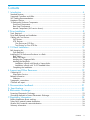
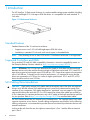
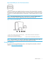
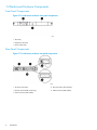
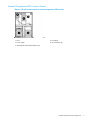
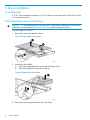
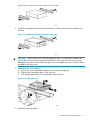
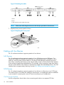
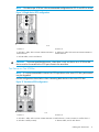
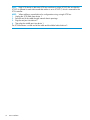
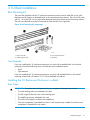
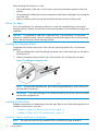
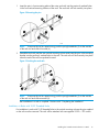
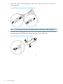
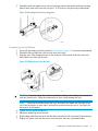
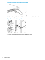
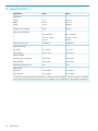
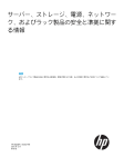
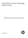
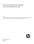
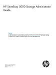
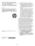
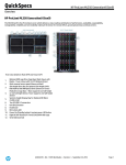
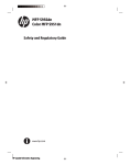
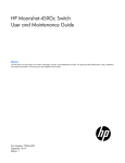
HP StoreEver
1U Rack-mount Enclosure User Guide
This document provides installation instructions and specifications for the HP StoreEver 1U rack-mount enclosures. It is intended
for system administrators and technicians experienced with installing tape drives and other hardware into a rack.
*606410-007*
HP Part Number: 606410-007
Published: September 2013
Edition: Fourth
© Copyright 2005, 2013 Hewlett-Packard Development Company, L.P.
The information contained herein is subject to change without notice. The only warranties for HP products and services are set forth in the express
warranty statements accompanying such products and services. Nothing herein should be construed as constituting an additional warranty. HP shall
not be liable for technical or editorial errors or omissions contained herein.
Warranty
WARRANTY STATEMENT: To obtain a copy of the warranty for this product, see the warranty information website:
http://www.hp.com/go/storagewarranty
Contents
1 Introduction...............................................................................................4
Standard Features.....................................................................................................................4
Supported Controllers and HBAs................................................................................................4
SAS Cabling Recommendations..................................................................................................4
Hardware Options....................................................................................................................5
1U Rack-mount Enclosure Components.........................................................................................6
Front Panel Components........................................................................................................6
Rear Panel Components .......................................................................................................6
Internal Components (SAS version shown)...............................................................................7
2 Drive Installation.........................................................................................8
Tools Required.........................................................................................................................8
Drive Blank Removal and Installation...........................................................................................8
Cabling with Two Devices........................................................................................................10
SAS Devices......................................................................................................................10
SCSI Devices.....................................................................................................................10
One Device per SCSI Bus...............................................................................................10
Two Devices on One SCSI Bus........................................................................................11
3 1U Rack Installation..................................................................................13
Rail Mounting Kit....................................................................................................................13
Tools Required...................................................................................................................13
Installing the 1U Rack-mount Enclosure in a Rack........................................................................13
Rack Safety.......................................................................................................................13
Before You Begin...............................................................................................................14
Installing the Component Rails.............................................................................................14
Installing the Rack Rails.......................................................................................................14
Installation in Racks with Round or Square Holes...............................................................14
Installation in Racks with 10-32 Threaded Holes................................................................15
Completing the Installation..................................................................................................17
4 Support and Other Resources.....................................................................19
Contacting HP........................................................................................................................19
Subscription Service...........................................................................................................19
Related information.................................................................................................................19
Websites..........................................................................................................................19
Typographic conventions.........................................................................................................19
Customer self repair................................................................................................................20
5 Documentation feedback...........................................................................21
A Specifications..........................................................................................22
B Electrostatic Discharge...............................................................................23
Preventing Electrostatic Discharge.............................................................................................23
Grounding Methods to Prevent Electrostatic Discharge.................................................................23
C Regulatory Information..............................................................................24
Belarus Kazakhstan Russia marking...........................................................................................24
Turkey RoHS material content declaration...................................................................................24
Ukraine RoHS material content declaration................................................................................24
Warranty information..............................................................................................................24
Contents
3
1 Introduction
The HP StoreEver 1U Rack-mount Enclosure is a rack-mountable storage system capable of holding
up to two half-height 5.25 inch tape or RDX disk drives. It is compatible with most standard 19
inch racks.
Figure 1 1U Rack-mount Enclosure
Standard Features
Standard features of the 1U rack-mount enclosure:
•
Supports one or two 5.25 inch half-height tape or RDX disk drives
•
Installation in standard 19 inch racks with round, square, or threaded holes
NOTE:
Daisy-chaining of two or more SCSI version 1U rack-mount enclosures is not supported.
Supported Controllers and HBAs
For up-to-date SCSI and SAS HBA compatibility information, review the compatibility matrix on
the Enterprise Backup Solutions website at: http://www.hp.com/storage/SPOCK.
NOTE: SCSI drives: The SCSI bus type determines the speed at which data can be transferred
between devices on the bus and the maximum length of cable that can be used. LTO–3 and LTO–4
tape drives support a burst transfer rate of 320 MB/sec. LTO–2 tape drives support a burst transfer
rate of 160 MB/sec. To benefit from this level of performance, it is important to ensure that the
drives are connected to a SCSI bus of a similar or higher specification. LTO–3 and LTO–4 SCSI
drives should be on their own SCSI bus.
SAS Cabling Recommendations
CAUTION: High quality external SAS cables rated at the transfer rate of the drive are required.
Always verify that the external SAS cable being used is rated for the data transfer speed of the
interface of your component. SAS cables described as "equalized" may not support 6 Gb/s data
rates and should not be used with LTO-5 or LTO-6 tape drives unless these cables are verified for
6 Gb/s data rates. For optimum performance, only use HP cables of the length specified as qualified
for your products. Refer to http://www.hp.com/storage/SPOCK for recommended cables.
The SAS interface board has two external ports illustrated below. The supplied internal SAS cable
supports connection of two devices. Several cabling configurations are possible, but the following
cabling configuration is recommended to provide the most consistent layout between devices and
external connectors.
Looking at the rack from the rear, the right-most external port is Port 1 and the left-most external
port is Port 2.
4
Introduction
Figure 2 External SAS ports on the 1U rack-mount enclosure
When two SAS devices are installed, the right–most connector of the internal cable is connected
to the device on the right and the left-most connector of the internal cable is connected to the device
on the left. This routes the right-hand device to external port 1 and the left-hand device to external
port 2.
NOTE: The interface board has text, “Port 1–0” and “Port 2–0”, on the PCI board near the
internal SAS connector, which also helps identify the routing to the external ports.
Figure 3 Enclosure internal SAS cable
1. and 3. Power connectors (used only with LTO-5, LTO-6,
and DAT; do not use with other LTO drives)
4. SAS connector routes device to external port 1
2. SAS connector routes device to external port 2
5. SAS connector to PC board within the enclosure
NOTE: Power for all DDS, LTO-5, and LTO–6 tape drives is supplied through the SAS cable. For
all earlier models of LTO tape drive, plug the power cable directly into the drive.
Hardware Options
For a list of currently supported hardware options, such as tape drives and media, visit the HP
website at: http://www.hp.com/go/tape.
Hardware Options
5
1U Rack-mount Enclosure Components
Front Panel Components
Figure 4 1U rack-mount enclosure front panel components
1. Drive bay
2. Expansion drive bay
3. Power switch/LED
Rear Panel Components
Figure 5 1U rack-mount enclosure rear panel components
1. AC Power Connector
2. SCSI Connector (SCSI models)
3. SCSI ID Switch (SCSI mode Only)
4. USB Connector (USB models)
5. SAS Connector (SAS models)
6
Introduction
Internal Components (SAS version shown)
Figure 6 1U rack-mount enclosure internal components (SAS version)
1. Drive
2. Drive blank
3. Power supply
4. Fan assemblies (2)
5. SAS Repeater Board (SAS Models only)
1U Rack-mount Enclosure Components
7
2 Drive Installation
Tools Required
A 3/16” (5mm) flat-blade screwdriver or T-15 Torx driver may be required to install a drive in the
1U rack-mount enclosure.
Drive Blank Removal and Installation
CAUTION: To avoid damaging the equipment due to electrostatic discharge, be sure to review
and practice the procedures in Electrostatic discharge before handling the drives.
To install a tape or disk drive:
1. Remove the top access panel as shown.
Figure 7 Removing the access panel
2.
Remove the drive blank:
a. Pull the spring-loaded button on the right mounting rail up.
b. Slide the assembly forward and then lift up.
Figure 8 Removing the drive blank
3.
8
Remove the mounting brackets from the drive blank.
Drive Installation
Figure 9 Removing the mounting brackets from the blank
4.
Install the mounting brackets to the sides of the drive. Always use the screws provided with
the drive.
Figure 10 Installing the mounting brackets on the drive
CAUTION: When installing an LTO half-height tape drive, it is particularly important that
you use the 6 mm M3 screws provided with the drive. If the screws are too long, they may
damage the mechanism and void the warranty. Do not overtighten the screws; use the washers
provided in the screw pack.
5.
Install the drive in the enclosure:
a. Position the mounting bracket keyhole slots over the mounting posts.
b. Slide the drive toward the back of the enclosure.
c. The spring-loaded button will automatically snap into place.
Figure 11 Installing the drive
6.
Attach the following cables:
Drive Blank Removal and Installation
9
Figure 12 Attaching the cables
1. Power
2. Data
3. SCSI ID selector switch (SCSI drives only)
NOTE:
7.
Fold excess cable length and secure with the clips provided in the enclosure.
Replace the top access panel as shown.
Figure 13 Replacing the access panel
Cabling with Two Devices
The 1U rack-mount enclosure supports operation of two devices.
SAS Devices
The 1U rack-mount enclosure supports operation of two SAS devices on two SAS buses. Two
internal SAS cables are installed in the enclosure, so completing the device installation is just a
matter of connecting each internal cable to a SAS device and cabling the external port to the
host. When connecting SAS devices to the internal cables, check to confirm that the SAS interface
in the enclosure supports the attached device. (For example, when connecting a tape drive device,
be sure to check that the SAS interface in the enclosure supports the attached tape drive.) The SAS
interface does not support daisy chaining. See also SAS cabling recommendations (page 4).
SCSI Devices
The 1U rack-mount enclosure supports operation of two devices on either one or two SCSI buses.
Two internal 2-port SCSI cables are installed in the enclosure, so completing the device installation
is just a matter of connecting the correct SCSI port according to your configuration.
One Device per SCSI Bus
Use the configuration shown below when connecting each device to a separate SCSI bus.
10
Drive Installation
NOTE:
One device per SCSI bus is the recommended configuration for LTO–3 and LTO–4 drives.
Figure 14 Single-device SCSI configuration
1. Device 1
2. Device 2
3. SCSI bus 1 cable, SCSI connector nearest terminator is 4. SCSI bus 2 cable, SCSI connector nearest terminator is
used for device 1
used for device 2
5. SCSI ID cables, one for each device
CAUTION: To prevent possible data errors, when there is only one device on a SCSI bus that
device must be connected to the SCSI port closest to the terminator.
Two Devices on One SCSI Bus
NOTE: It is not recommended to connect two LTO tape drives to the same SCSI bus; performance
may be degraded.
Use the configuration shown below when connecting both devices to the same SCSI bus.
Figure 15 Two-device SCSI configuration
1. Device 1
2. Device 2
3. SCSI bus 1 cable; SCSI connector nearest terminator is used for device 2, center connector is used for device 1
4. SCSI bus 2 cable (not used)
5. SCSI ID cables, one for each device
Cabling with Two Devices
11
NOTE: Each SCSI device on the same SCSI bus must have a unique SCSI ID. Be sure that the
SCSI ID is different for each device and that neither is set to SCSI ID 7, which is reserved for the
SCSI controller.
NOTE: When adding a second device for configurations using a single SCSI bus.
1. Unplug the SCSI cable from device 1.
2. Pass the end of the cable through internal chassis openings.
3. Plug the end port into device 2.
4. Then plug the middle port into device 1.
The SCSI terminator is at the end of the cable and should be behind device 2.
12
Drive Installation
3 1U Rack Installation
Rail Mounting Kit
The rack rails supplied with the 1U rack-mount enclosure can be used to install the unit in racks
that have round, square, or threaded holes in the vertical mounting columns. The rails will fit racks
with 23 - 34 inches (58 - 86 cm) separation between the front and rear vertical mounting columns.
The rails are identical and may be mounted on either the left or the right side.
Figure 16 Rail mounting kit components
1. Outer rack rails
2. Inner component rails
3. Cable support clips
4. Fasteners
Tools Required
If you are installing the 1U rack-mount enclosure in a rack with unmarked holes in the vertical
mounting columns the following items will make the rack installation easier:
•
Pencil
•
Tape measure
If you are installing the 1U rack-mount enclosure in a rack with threaded holes in the vertical
mounting columns you will need a 3/16” (5mm) flat-blade screwdriver.
Installing the 1U Rack-mount Enclosure in a Rack
Rack Safety
WARNING!
To reduce the risk of personal injury or equipment damage, be sure that:
•
The rack leveling jacks are extended to the floor
•
The full weight of the rack rests on the leveling jacks
•
The stabilizing feet are attached to the rack
•
The racks are coupled in multiple rack installations
•
Only one component is extended at a time. A rack may become unstable if more than one
component is extended for any reason.
Rail Mounting Kit
13
When installing the enclosure in a rack:
•
Start at the bottom of the rack, or at the top of a previously mounted component, and work
upward
•
HP recommends installing the heaviest components at the bottom and lighter ones toward the
top of the rack
•
Make sure that the rack-mounting rails are level from front to back and side to side
Before You Begin
If you are installing the 1U rack-mount enclosure in a rack with unmarked holes in the vertical
mounting columns, identify and mark the correct mounting holes in the rack before you begin rail
installation.
CAUTION: It is important to install rack components level. To ensure that the 1U rack-mount
enclosure is installed correctly it may be necessary to measure the height of the correct mounting
holes in the front and rear vertical mounting columns.
Installing the Component Rails
Component rails are the inner portion of the rack rail system that attach to the 1U rack-mount
enclosure.
1. Align the slotted holes on the left and right component rails with the three pins on the sides of
the enclosure (1).
2. Slide the component rails toward the rear of the enclosure (2) until they lock into place.
Figure 17 Installing the component rails
NOTE: To remove the component rail, pull out the spring-loaded tab (3) on the side of the
rail and slide it forward (4).
IMPORTANT: If you are returning the 1U rack-mount enclosure for service, be sure to remove
and save the component rail.
Installing the Rack Rails
Installation procedures vary depending on the rack type. Refer to one of the following sections for
installation instructions for your rack:
•
“Installation in Racks with Round or Square Holes” (page 14)
•
“Installation in Racks with 10-32 Threaded Holes” (page 15)
Installation in Racks with Round or Square Holes
NOTE:
14
The ends of the rack rails are marked FRONT and REAR for proper orientation.
1U Rack Installation
1.
Insert the pins in front mounting plate of the outer rack rails into the previously marked holes
in the front vertical mounting columns of the rack. The rack rails will lock securely into place.
Figure 18 Inserting the pins
NOTE: To remove the rail for repositioning, push the spring-loaded tab (3) on the outside
of the rack rail and slide it forward (4).
2.
Extend the rack rails past the rear vertical mounting column and insert the pins in the mounting
bracket into the previously marked holes in the rack. The rack rails will lock securely into place
when the end of the rails are pushed forward.
Figure 19 Locking the rack rails
NOTE: To remove the rail for repositioning, push the spring-loaded tab (3) on the outside
of the rack rail and slide rearward (4).
Rail installation in a rack is complete. Continue with ”Completing the installation”
Installation in Racks with 10-32 Threaded Holes
For installation in racks with 10-32 threaded holes in the vertical mounting columns the pins supplied
on the rails must be removed. The rails will be attached with user-supplied 10-32 x .375 screws.
Installing the 1U Rack-mount Enclosure in a Rack
15
1.
Remove the pins and threaded plates from both ends of each outer rack rail. These pieces
will not be used.
Figure 20 Removing the pins and threaded plates
NOTE:
2.
The ends of the rack rails are marked FRONT and REAR for proper orientation.
Attach the front mounting plate of each outer rail to the rack using four 10-32 screws in the
previously marked holes in the front vertical mounting columns of the rack.
Figure 21 Attaching the front mounting plate
16
1U Rack Installation
3.
Extend the rack rails past the rear vertical mounting columns and attach the back mounting
plate of each outer rail to the rack using four 10-32 screws in the previously marked holes.
Figure 22 Attaching the back mounting plate
Completing the Installation
1.
2.
3.
Ensure all rack safety precautions stated in “Rack Safety” (page 13) have been implemented.
Extend the left and right rack rails from the front of the rack.
Align the rear of the component rails on the enclosure with the front ends of the rack rails,
then slide the unit fully into the rack.
Figure 23 Sliding the unit into the rack
CAUTION: Be sure to keep the enclosure parallel to the floor when sliding the component
rails into the rack rails. Tilting the enclosure up or down could damage the rails.
NOTE: To remove the enclosure from the rack, disconnect the cables from the back of the
unit. Press the latches on each side 3 and pull the enclosure from the rack 4. See Figure for
the location of the latches.
4.
5.
6.
7.
Tighten the front panel thumbscrews.
Retract the stabilizing feet of the rack.
Plug the data cable from the server into the data connectors on the rear panel of the enclosure.
Plug the AC power cord into the power cord connector, then into a grounded outlet.
Installing the 1U Rack-mount Enclosure in a Rack
17
Figure 24 Connecting the power cord (USB drive installed)
8.
Install the cable support clips at the back of the rack rails on one or both sides of the enclosure.
Figure 25 Installing the cable support clips
9.
18
Turn on the power to the enclosure with the front panel power button.
1U Rack Installation
4 Support and Other Resources
Contacting HP
For worldwide technical support information, see the HP support website:
http://www.hp.com/support
Before contacting HP, collect the following information:
•
Product model names and numbers
•
Technical support registration number (if applicable)
•
Product serial numbers
•
Error messages
•
Operating system type and revision level
•
Detailed questions
Subscription Service
HP strongly recommends that customers register online using the Subscriber's choice web site:
http://www.hp.com/go/e-updates.
Subscribing to this service provides you with e-mail updates on the latest product enhancements,
newest driver versions, and firmware documentation updates as well as instant access to numerous
other product resources.
After subscribing, locate your products by selecting Business support and then Storage under
Product Category.
Related information
See the documentation provided with the drive installed in the enclosure.
Websites
•
HP StoreEver Tape Systems website: http://www.hp.com/go/tape
•
HP Technical Support website: http://www.hp.com/support
•
Single Point of Connectivity Knowledge (SPOCK) website: http://www.hp.com/storage/spock
•
White papers and Analyst reports: http://www.hp.com/storage/whitepapers
Typographic conventions
Table 1 Document conventions
Convention
Element
Blue text: Table 1 (page 19)
Cross-reference links
Blue, bold, underlined text
email addresses
Blue, underlined text: http://www.hp.com
Website addresses
Bold text
• Keys that are pressed
• Text typed into a GUI element, such as a box
• GUI elements that are clicked or selected, such as menu
and list items, buttons, tabs, and check boxes
Italic text
Text emphasis
Contacting HP
19
Table 1 Document conventions (continued)
Convention
Element
Monospace text
• File and directory names
• System output
• Code
• Commands, their arguments, and argument values
Monospace, italic text
• Code variables
• Command variables
Monospace, bold text
WARNING!
CAUTION:
IMPORTANT:
NOTE:
TIP:
Emphasized monospace text
Indicates that failure to follow directions could result in bodily harm or death.
Indicates that failure to follow directions could result in damage to equipment or data.
Provides clarifying information or specific instructions.
Provides additional information.
Provides helpful hints and shortcuts.
Customer self repair
HP customer self repair (CSR) programs allow you to repair your HP product. If a CSR part needs
replacing, HP ships the part directly to you so that you can install it at your convenience. Some
parts do not qualify for CSR. Your HP-authorized service provider will determine whether a repair
can be accomplished by CSR.
For more information about CSR, contact your local service provider, or see the CSR website:
http://www.hp.com/go/selfrepair
20
Support and Other Resources
5 Documentation feedback
HP is committed to providing documentation that meets your needs. To help us improve the
documentation, send any errors, suggestions, or comments to Documentation Feedback
([email protected]). Include the document title and part number, version number, or the URL
when submitting your feedback.
21
A Specifications
Specification
S.A.E.
Metric
Height
1.7 in
4.32 cm
Depth
25.3 in
64.14 cm
Width
19.0 in
42.88 cm
Weight (1 drive installed)
20 lb
9.07 kg
90 to 264 VAC
90 to 264 VAC
2.4 A 47 - 63 Hz
2.4 A 47 - 63 Hz
140 W*
140 W*
478 BTU/hr*
478 BTU/hr*
Operating
41° to 95° F
5° to 35° C
Non-operating
-40° to 150° F
-40° to 66° C
Operating (non-condensing)
20% to 80%
20% to 80%
Non-operating
10% to 95%
10% to 95%
Wet bulb temperature (max)
79° F
26° C
Operating
0 to 13,000 ft
0 to 4000 m
Non-operating
0 to 50,000 ft
0 to 15200 m
Dimensions:
Input power requirements
Heat Dissipation (max)
Temperature range
Relative humidity
Altitude (max)
* Input power and Heat dissipation specifications are maximum values and apply to worst-case conditions at full rated
power supply load. The power/heat dissipation for your installation will vary depending on the equipment configuration.
22
Specifications
B Electrostatic Discharge
Preventing Electrostatic Discharge
To prevent damaging the system, be aware of the precautions you need to follow when setting up
the system or handling parts. A discharge of static electricity from a finger or other conductor may
damage system boards or other static-sensitive devices. This type of damage may reduce the life
expectancy of the device.
To prevent electrostatic damage:
•
Avoid hand contact by transporting and storing products in static-safe containers.
•
Keep electrostatic-sensitive parts in their containers until they arrive at static-free workstations.
•
Place parts on a grounded surface before removing them from their containers.
•
Avoid touching pins, leads, or circuitry.
•
Always be properly grounded when touching a static-sensitive component or assembly.
Grounding Methods to Prevent Electrostatic Discharge
Several methods are used for grounding. Use one or more of the following methods when handling
or installing electrostatic-sensitive parts:
•
Use a wrist strap connected by a ground cord to a grounded workstation or computer chassis.
Wrist straps are flexible straps with a minimum of 1 megohm.
±10 percent resistance in the ground cords. To provide proper ground, wear the strap snug
against the skin.
•
Use heel straps, toe straps, or boot straps at standing workstations. Wear the straps on both
feet when standing on conductive floors or dissipating floor mats.
•
Use conductive field service tools.
•
Use a portable field service kit with a folding static-dissipating work mat.
If you do not have any of the suggested equipment for proper grounding, have an authorized
reseller install the part.
For more information on static electricity or assistance with product installation, contact an authorized
reseller.
Preventing Electrostatic Discharge
23
C Regulatory Information
For important safety, environmental, and regulatory information, see Safety and Compliance
Information for Server, Storage, Power, Networking, and Rack Products, available at http://
www.hp.com/support/Safety-Compliance-EnterpriseProducts. This document may also be included
with the shipped product as a printed document or on a documentation CD/DVD.
Belarus Kazakhstan Russia marking
Manufacturer and Local Representative Information
Manufacturer’s information:
•
Hewlett-Packard Company, 3000 Hanover Street, Palo Alto, California 94304, U.S.
Local Representative information Russian:
•
HP Russia: ЗАО “Хьюлетт-Паккард А.О.”, 125171, Россия, г. Москва, Ленинградское
шоссе, 16А, стр.3, тел/факс: +7 (495) 797 35 00, +7 (495) 287 89 05
•
HP Belarus: ИООО «Хьюлетт-Паккард Бел», 220030, Беларусь, г. Минск, ул.
Интернациональная, 36-1, офис 722-723, тел.: +375 (17) 392 28 18, факс: +375 (17)
392 28 21
•
HP Kazakhstan: ТОО «Хьюлетт-Паккард (К), 050040, Казахстан, г. Алматы, Бостандыкский
район, ул. Тимирязева, 28В, 1 этаж, тел./факс: +7 (727) 355 35 50, +7 (727) 355 35
51
Local Representative information Kazakh:
•
HP Kazakhstan: ЖШС «Хьюлетт-Паккард (К)», Қазақстан, Алматы қ., Бостандық ауданы,
Тимирязев к-сі, 28В, тел./факс: +7 (727) 355 35 50, +7 (727) 355 35 51
Manufacturing date:
The manufacturing date is defined by the serial number.
CCSYWWZZZZ (HP serial number format for this product)
Valid date formats include:
•
YWW, where Y indicates the year counting from within each new decade, with 2000 as the
starting point; for example, 238: 2 for 2002 and 38 for the week of September 9. In addition,
2010 is indicated by 0, 2011 by 1, 2012 by 2, 2013 by 3, and so forth.
•
YYWW, where YY indicates the year, using a base year of 2000; for example, 0238: 02
for 2002 and 38 for the week of September 9.
Turkey RoHS material content declaration
Türkiye Cumhuriyeti: EEE Yönetmeliğine Uygundur
Ukraine RoHS material content declaration
Обладнання відповідає вимогам Технічного регламенту щодо обмеження використання деяких
небезпечних речовин в електричному та електронному обладнанні, затвердженого постановою
Кабінету Міністрів України від 3 грудня 2008 № 1057
Warranty information
HP ProLiant and X86 Servers and Options
http://www.hp.com/support/ProLiantServers-Warranties
24
Regulatory Information
HP Enterprise Servers
http://www.hp.com/support/EnterpriseServers-Warranties
HP Storage Products
http://www.hp.com/support/Storage-Warranties
HP Networking Products
http://www.hp.com/support/Networking-Warranties
Warranty information
25