1
HP Smart Array P800 Controller
for Integrity Servers
User Guide
October 2006 (Second Edition)
Part Number 432599-002
© Copyright 2006 Hewlett-Packard Development Company, L.P.
The information contained herein is subject to change without notice. The only warranties for HP products and services are set forth in the express
warranty statements accompanying such products and services. Nothing herein should be construed as constituting an additional warranty. HP
shall not be liable for technical or editorial errors or omissions contained herein.
Microsoft and Windows are U.S. registered trademarks of Microsoft Corporation.
October 2006 (Second Edition)
Part Number 432599-002
Audience assumptions
This document is for the person who installs, administers, and troubleshoots servers and storage systems.
HP assumes you are qualified in the servicing of computer equipment and trained in recognizing hazards
in products with hazardous energy levels.
Contents
Hardware features ........................................................................................................................ 5
Main components on the board .................................................................................................................. 5
Controller specifications ............................................................................................................................. 5
Overview of the installation procedure ............................................................................................ 7
Quick installation procedure (Windows or Linux)........................................................................................... 7
Installing the controller hardware .................................................................................................... 9
Before beginning the installation ................................................................................................................. 9
Preparing the server................................................................................................................................... 9
Installing the controller board...................................................................................................................... 9
Connecting storage devices ...................................................................................................................... 10
Connecting internal storage ............................................................................................................ 10
Connecting external storage ........................................................................................................... 10
SAS cable part numbers ................................................................................................................. 11
Updating the firmware ................................................................................................................ 12
Methods for updating the firmware (Windows® or Linux®) .......................................................................... 12
Configuring an array .................................................................................................................. 13
Utilities available for configuring an array .................................................................................................. 13
Comparing the utilities ............................................................................................................................. 13
Using ORCA........................................................................................................................................... 14
Using ACU ............................................................................................................................................. 15
Installing device drivers and Management Agents .......................................................................... 16
Systems using Microsoft® Windows®........................................................................................................ 16
Installing device drivers .................................................................................................................. 16
Installing the Event Notification Service ............................................................................................ 16
Installing Management Agents ........................................................................................................ 16
Systems using Linux®............................................................................................................................... 16
Installing Management Agents ........................................................................................................ 17
Upgrading or replacing controller options ..................................................................................... 18
Replacing or adding a battery .................................................................................................................. 18
Replacing the cache module or controller ................................................................................................... 22
Replacing, moving, or adding hard drives ..................................................................................... 26
Identifying the status of a hard drive .......................................................................................................... 26
Recognizing hard drive failure .................................................................................................................. 27
Effects of a hard drive failure .......................................................................................................... 28
Compromised fault tolerance .......................................................................................................... 28
Recovering from compromised fault tolerance.................................................................................... 28
Replacing hard drives .............................................................................................................................. 29
Factors to consider before replacing hard drives................................................................................ 29
Automatic data recovery (rebuild) .................................................................................................... 29
Upgrading hard drive capacity ....................................................................................................... 31
Moving drives and arrays ........................................................................................................................ 32
Adding drives ......................................................................................................................................... 32
Diagnosing array problems.......................................................................................................... 34
Controller board runtime LEDs................................................................................................................... 34
Battery pack LEDs.................................................................................................................................... 35
Contents
3
Diagnostic tools ...................................................................................................................................... 36
Electrostatic discharge ................................................................................................................. 37
Preventing electrostatic discharge .............................................................................................................. 37
Grounding methods to prevent electrostatic discharge .................................................................................. 37
Regulatory compliance notices ..................................................................................................... 38
Federal Communications Commission notice............................................................................................... 38
Modifications.......................................................................................................................................... 38
Cables ................................................................................................................................................... 38
Canadian notice ..................................................................................................................................... 38
European Union regulatory notice ............................................................................................................. 39
BSMI notice ............................................................................................................................................ 39
Japanese class A notice ........................................................................................................................... 39
Korean class A notice .............................................................................................................................. 40
Battery replacement notice........................................................................................................................ 40
Taiwan battery recycling notice................................................................................................................. 40
Acronyms and abbreviations........................................................................................................ 41
Index......................................................................................................................................... 43
Contents
4
Hardware features
In this section
Main components on the board ................................................................................................................. 5
Controller specifications ............................................................................................................................ 5
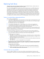
Main components on the board
Item ID
Description
1
Connector for SAS miniports 1E and 2E (external), each 4x wide
2
Heartbeat LED (flashes green when operating normally and amber
if the board has failed)
3
Activity LED for external ports
4
SAS port 3I (internal), 4x wide
5
SAS port 4I (internal), 4x wide
6
Cache module (also known as BBWC or array accelerator)
7
Batteries for cache module (Two batteries are normally sufficient,
but a third can be added to provide extra security against loss of
system power.)
Controller specifications
Feature
Details
Card type
Full-size PCIe
Hardware features
5
Dimensions (excluding bracket)
31.1 cm × 11.1 cm × 1.2 cm (12.3 in × 4.4 in × 0.5 in)
Type of drives supported
3 Gb/s SAS or 1.5 Gb/s SATA
Maximum power required
Approximately 25 W
Temperature range
Operating, 10° to 55°C (50° to 131°F)
Storage, -30° to 60°C (-22° to 140°F)
Relative humidity
(noncondensing)
Operating, 10% to 90%
Storage, 5% to 90%
RAID levels supported
0, 1, 1+0, and 5; also 6 if the batteries are used
Type of edge connector
PCIe x8
PCIe transfer rate
Up to 2 GB/s in each direction
Number of SAS ports
Two internal, two external; each port has four 1x links
Maximum number of physical
drives (using all four ports)
108 (8 can be connected internally, and a further 100 can be
connected externally by using expanders)
Maximum number of logical
drives
32
Maximum size of a logical drive
More than 2 TB
SAS transfer rate
Up to 1.2 GB/s per port in each direction
Spare battery part number
398648-001
Time required to recharge
battery
From 15 minutes to 2 hours, depending on the initial battery charge
level
Duration of battery backup
More than 2 days if the batteries are fully charged and less than 3
years old
Battery life expectancy
More than 3 years
Cache size
512 MB (48 MB is used by the onboard processor)
For more information about the controller features and specifications, and for information about system
requirements, refer to the HP website (http://www.hp.com/products/smartarray).
Hardware features
6
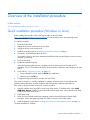
Overview of the installation procedure
In this section
Quick installation procedure (Windows or Linux) ......................................................................................... 7
Quick installation procedure (Windows or Linux)
Before installing the controller, refer to the support matrix on the HP website
(http://www.hp.com/products1/serverconnectivity) to confirm that the server and operating system
support the controller.
To install the controller:
1.
Power down the server.
2.
Unplug the AC power cord from the power outlet.
3.
Unplug the power cord from the server.
4.
Install the controller hardware ("Installing the controller hardware" on page 9).
5.
If necessary, install additional physical drives.
The number of drives in the server determines the RAID level that is autoconfigured when the server is
powered up (next step).
6.
Power up the server.
7.
Update the controller firmware.
When the firmware update process is complete, the server reboots and runs through a POST
procedure. This POST procedure halts briefly during controller initialization and prompts you to open
ORCA.
8.
9.
Open ORCA ("Configuring an array" on page 13).
•
If using a headless console, press the Esc+8 key combination.
•
Otherwise, press the F8 key.
Configure the logical boot drive, and then exit from ORCA.
If the server is using Linux, controller installation is complete. When the server is next rebooted, the
operating system detects the controller hardware and automatically installs the required driver.
If the server is using Microsoft® Windows®, continue as follows:
1.
Load the controller driver from EBSU on the Smart Setup media. (To load the driver, select Load
OEM Boot Drivers in EBSU. For more information about Smart Setup, refer to the HP Smart Setup
Guide on the Smart Setup media.)
2.
Run Express Setup.
3.
When you have finished installing the operating system as directed during the Express Setup
procedure, remove the operating system CD, and then insert the Smart Setup media.
4.
Install the Integrity Support Pack ("Installing device drivers and Management Agents" on page 16).
Controller installation is complete.
Overview of the installation procedure 7
The latest firmware, drivers, utilities, software, and documentation for HP Integrity servers are available on
the support page of the HP website (http://www.hp.com/support/itaniumservers).
Overview of the installation procedure 8
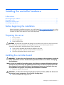
Installing the controller hardware
In this section
Before beginning the installation ................................................................................................................ 9
Preparing the server ................................................................................................................................. 9
Installing the controller board .................................................................................................................... 9
Connecting storage devices..................................................................................................................... 10
Before beginning the installation
Before beginning the installation procedure, visit the HP website (http://www.hp.com/support) to confirm
that you have the latest version of each driver and utility file needed. Compare the version numbers of the
files there with those of the same files on the Smart Setup media.
Preparing the server
1.
Back up all data.
2.
Close all applications.
3.
Power down the server.
CAUTION: In systems that use external data storage, be sure that the server is the first unit to be powered
down and the last to be powered back up. Taking this precaution ensures that the system does not
erroneously mark the drives as failed when the server is powered up.
4.
Power down all peripheral devices that are attached to the server.
5.
Unplug the AC power cord from the outlet and then from the server.
6.
Disconnect all peripheral devices from the server.
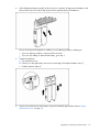
Installing the controller board
WARNING: To reduce the risk of personal injury or damage to the equipment, consult the
safety information and user documentation provided with the server before attempting
the installation.
Many servers are capable of providing energy levels that are considered hazardous and are
intended to be serviced only by qualified personnel who have been trained to deal with
these hazards. Do not remove enclosures or attempt to bypass any interlocks that may
be provided for the purpose of removing these hazardous conditions.
1.
Remove or open the access panel.
WARNING: To reduce the risk of personal injury from hot surfaces, allow the drives and
the internal system components to cool before touching them.
2.
Select an available x8 or larger PCIe slot.
Installing the controller hardware 9
3.
Remove the slot cover. Save the retaining screw, if one is present.
4.
Slide the controller board along the slot alignment guide, if one is present, and press the board
firmly into the slot so that the contacts on the board edge are properly seated in the system board
connector.
5.
Secure the controller board in place with the retaining screw. If the slot alignment guide has a latch
(near the rear of the board), close the latch.
6.
Connect storage devices to the controller. (For details of the procedure, see "Connecting storage
devices (on page 10).")
7.
Close or replace the access panel, and secure it with thumbscrews, if any are present.
CAUTION: Do not operate the server for long periods with the access panel open or removed. Operating
the server in this manner results in improper airflow and improper cooling that can lead to thermal damage.
Connecting storage devices
You can connect SAS or SATA drives to the controller internally ("Connecting internal storage" on page
10) or externally ("Connecting external storage" on page 10).
For information about supported drive models, see the controller-specific page on the HP website
(http://www.hp.com/products/smartarray).
Connecting internal storage
1.
Power down the server.
2.
Install hard drives, if necessary. If you want to group some of the drives in an array, they must meet
the following criteria:
•
They must be of the same type, either all SAS or all SATA. (This controller does not support
parallel SCSI drives.)
•
For efficient use of drive space, they must have comparable capacity.
For additional information about drive installation, see the appropriate section in this guide
("Replacing, moving, or adding hard drives" on page 26) and consult the server documentation and
the documentation that accompanied the drives.
3.
4.
Use the internal wide SAS cable provided with the server to connect the controller to the drives.
•
If the drives are hot-plug capable, connect the internal connector of the controller to the SAS
connector on the hot-plug drive cage.
•
If the drives are not hot-plug capable, connect the internal connector of the controller to the nonhot-plug hard drives.
Close or replace the access panel, and secure it with thumbscrews, if any are present.
CAUTION: Do not operate the server for long periods with the access panel open or removed. Operating
the server in this manner results in improper airflow and improper cooling that can lead to thermal damage.
5.
Power up the server.
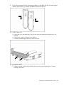
Connecting external storage
1.
Power down the server.
2.
Connect an external SAS cable to the external port of the controller.
a. Pull back the tab on the mini SAS 4x connector on the cable.
b. Insert the cable connector into the external port of the controller.
Installing the controller hardware 10
c. Release the tab.
3.
Connect the other end of the cable to the SAS input connector of the external storage enclosure.
•
If the enclosure uses a standard SAS 4x connector, insert the cable connector into the enclosure
connector, and then tighten the lock screws on the cable connector.
•
If the enclosure uses a mini SAS 4x connector, pull back the tab on the cable connector, insert
the cable connector into the enclosure connector, and then release the tab.
4.
Power up the enclosure.
5.
Power up the server.
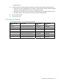
SAS cable part numbers
To order additional cables, use the option kit part number.
Approximate cable
length
Type of cable
Option kit part
number
Cable assembly
number
1 m (3 ft)
Mini SAS 4x to standard SAS 4x
419570-B21
408908-002
2 m (6 ft)
Mini SAS 4x to mini SAS 4x
407339-B21
407344-003
Mini SAS 4x to standard SAS 4x
419571-B21
408908-003
Mini SAS 4x to mini SAS 4x
432238-B21
407344-004
Mini SAS 4x to standard SAS 4x
419572-B21
408908-004
Mini SAS 4x to mini SAS 4x
432239-B21
407344-005
Mini SAS 4x to standard SAS 4x
419537-B21
408908-005
4 m (13 ft)
6 m (20 ft)
Installing the controller hardware 11
Updating the firmware
In this section
Methods for updating the firmware (Windows® or Linux®)......................................................................... 12
Methods for updating the firmware (Windows® or Linux®)
To update the firmware on the server, controller, or hard drives, use Smart Components. The most recent
version of a particular component is available on the support page of the HP website
(http://www.hp.com/support). Some components are also available on the Smart Setup media.
1.
Find the most recent version of the component that you require.
2.
Follow the instructions for installing the component on the server. These instructions are provided on
the same Web page as the component.
3.
Follow the additional instructions that describe how to use the component to flash the ROM. These
instructions are provided with each component.
Updating the firmware 12
Configuring an array
In this section
Utilities available for configuring an array................................................................................................. 13
Comparing the utilities ............................................................................................................................ 13
Using ORCA.......................................................................................................................................... 14
Using ACU ............................................................................................................................................ 15
Utilities available for configuring an array
Two utilities are available for configuring an array on an HP Smart Array controller in an HP Integrity
server: ORCA and ACU.
•
ORCA is a simple utility that is used mainly to configure the first logical drive in a new server before
the operating system is loaded.
•
ACU is an advanced utility that enables you to perform many complex configuration tasks.
For more information about the features of these utilities and for instructions for using the utilities, see the
Configuring Arrays on HP Smart Array Controllers Reference Guide. This guide is available on the
Documentation CD that is provided in the controller kit.
Whichever utility you use, remember the following factors when you build an array:
•
All drives in an array must be of the same type (for example, all SAS or all SATA).
•
For the most efficient use of drive space, all drives within an array should have approximately the
same capacity. Each configuration utility treats every physical drive in an array as if it has the same
capacity as the smallest drive in the array. Any excess capacity of a particular drive cannot be used
in the array and so is unavailable for data storage.
•
The more physical drives that an array has, the greater the probability that the array will experience
a drive failure during any given period. To guard against the data loss that occurs when a drive
fails, configure all logical drives in an array with a suitable fault-tolerance (RAID) method.
Comparing the utilities
NOTE: A + in the appropriate column indicates that the feature or procedure is supported, while -- indicates
that the feature or procedure is not supported.
Supported features
ACU
ORCA
Uses a graphical interface
+
--
Available in languages other than English
+
--
Available on CD
+
--
Uses a wizard to suggest the optimum configuration for an unconfigured controller +
--
Describes configuration errors
+
--
Suitable for configuration while online
+
--
Suitable for configuration while offline
--
+
Configuring an array 13
Supported procedures
ACU
ORCA
Creation and deletion of arrays and logical drives
+
+
Assignment of RAID level
+
+
Sharing of spare drives among several arrays
+
--
Assignment of multiple spare drives per array
+
--
Setting of stripe size
+
--
Migration of RAID level or stripe size
+
--
Configuration of controller settings
+
--
Expansion of an array
+
--
Creation of multiple logical drives per array
+
--
Using ORCA
1.
Power up the server. POST runs, and any array controllers that are in the server are initialized one at
a time. During each controller initialization process, POST halts for several seconds while an ORCA
prompt message appears.
2.
At the ORCA prompt:
•
If you are connected using a headless console, press the Esc+8 key combination.
•
Otherwise, press the F8 key.
The ORCA main menu appears, enabling you to create, view, or delete a logical drive.
To create a logical drive using ORCA:
1.
Select Create Logical Drive.
The screen displays a list of all available (unconfigured) physical drives and the valid RAID options
for the system.
2.
Use the Arrow keys, Spacebar, and Tab key to navigate around the screen and set up the
logical drive, including an online spare drive if one is required.
NOTE: You cannot use ORCA to configure one spare drive to be shared among several arrays. Only ACU
enables you to configure shared spare drives.
3.
Press the Enter key to accept the settings.
4.
Press the F8 key to confirm the settings and save the new configuration.
After several seconds, the Configuration Saved screen appears.
5.
Press the Enter key to continue.
You can now create another logical drive by repeating the previous steps.
Configuring an array 14
NOTE: Newly created logical drives are invisible to the operating system. To make the new logical drives
available for data storage, format them using the instructions given in the operating system documentation.
Using ACU
For detailed information about using ACU, see the Configuring Arrays on HP Smart Array Controllers
Reference Guide. This document is available on the Smart Setup media or the Documentation CD that is
provided in the controller kit.
Configuring an array 15
Installing device drivers and Management
Agents
In this section
Systems using Microsoft® Windows® ...................................................................................................... 16
Systems using Linux®.............................................................................................................................. 16
Systems using Microsoft® Windows®
You can use the Integrity Support Pack to automatically install the device drivers, Event Notification
Service, and Management Agents, or you can install these items manually.
The Integrity Support Pack is located on the Smart Setup media. To install the Integrity Support Pack,
launch Express Setup from EBSU and follow the on-screen instructions.
Installing device drivers
The drivers for the controller are located on the Smart Setup media. Updates are posted to the support
page of the HP website (http://www.hp.com/support/itaniumservers).
Installation instructions are provided with the drivers.
Installing the Event Notification Service
The HP Smart Array SAS/SATA Event Notification Service provides event notification to the Microsoft®
Windows® Server 2003 64-bit system event log and the HP Integrated Management log.
The most recent version of the software component is available on the support page of the HP website
(http://www.hp.com/support/itaniumservers). Installation instructions are provided with the component.
Installing Management Agents
The Management Agents are available on the Smart Setup media. The most recent versions of the agents
are available on the support page of the HP website (http://www.hp.com/support/itaniumservers).
Installation instructions are provided with the agents.
If the new agents do not function correctly, you might also need to update Systems Insight Manager. The
latest version of Systems Insight Manager is available for download at the HP website
(http://www.hp.com/servers/manage).
Systems using Linux®
The drivers for the controller are bundled into the supported Red Hat and Novell Linux distributions.
In a system that does not yet have Linux installed:
1.
Follow the standard controller installation procedure.
Installing device drivers and Management Agents
16
2.
Reboot the server.
3.
Follow the standard procedure for installing Linux. As Linux is installed, it recognizes the controller
and automatically loads the correct driver.
In a system that already has Linux installed:
1.
Power down the system.
2.
Follow the standard controller installation procedure.
3.
Power up the system. As Linux boots, it recognizes the controller.
4.
Enter one of the following commands as appropriate to ensure that the driver is loaded correctly:
Red Hat: #mkinitrd -f /boot/efi/efi/redhat/initrd-$(uname -r).img $(uname
-r)
Novell (SLES): #mkinitrd -k /boot/vmlinux -i/boot/initrd
5.
For Novell, enter the following command to confirm that the driver is active:
#lsmod | grep cciss
If the driver is active, the system responds by displaying cciss.
Installing Management Agents
The most recent versions of the agents are available on the support page of the HP website
(http://www.hp.com/support/itaniumservers). For installation instructions, refer to the downloadable file
HP Insight Management Agents for Linux on Integrity Servers provided with the agents.
If the new agents do not function correctly, you might also need to update Systems Insight Manager. The
latest version of Systems Insight Manager is available for download at the HP website
(http://www.hp.com/servers/manage).
Installing device drivers and Management Agents
17
Upgrading or replacing controller options
In this section
Replacing or adding a battery ................................................................................................................. 18
Replacing the cache module or controller.................................................................................................. 22
Replacing or adding a battery
CAUTION: Electrostatic discharge can damage electronic components. Be sure you are properly grounded
before beginning this procedure. For more information, see "Electrostatic Discharge (on page 37)."
1.
Close all applications, and then power down the server. This procedure flushes all data from the
cache.
2.
Observe the BBWC Status LED ("Battery pack LEDs" on page 35).
•
If the LED is blinking every 2 seconds, data is still trapped in the cache. Restore system power,
and repeat the previous steps in this procedure.
•
If the LED is not lit, proceed with the next step.
WARNING: There is a risk of explosion, fire, or personal injury if the battery pack is not
properly handled. Refer to "Battery replacement notice (on page 40)" before installing or
removing any item that contains a battery pack.
3.
Remove the controller from the server.
4.
Pull the flanges on the battery clip outward (1), and then swivel the clip 180 degrees so that it rests
on the batteries (2).
5.
Slide the batteries toward the right edge of the controller, away from the bracket.
Upgrading or replacing controller options 18
6.
While holding the battery assembly, tilt the clip until it is at about 30 degrees to the batteries, and
then push the clip in line with the clip hinges until the clip detaches from the batteries.
The rest of the procedure depends on whether you are replacing a battery or adding one.
7.
•
If you are replacing a battery, continue with the next step.
•
If you are only adding an optional third battery, go to step 9.
Separate the batteries.
a. Turn the batteries over.
b. Pull the lip on the right battery case away from the edge of the adjacent battery case (1).
c. Slide the batteries apart (2).
8.
Dispose of the exhausted or faulty battery using environmentally approved procedures ("Battery
replacement notice" on page 40).
Upgrading or replacing controller options 19
9.
Position the new battery and the remaining good battery as indicated, and then push them together
and slide them until they are aligned. The batteries combine into one unit.
10. Install the battery clip.
a. Position the clip so that the hinges on the clip are next to the appropriate hinge pillars on the
batteries.
b. Hold the clip at about 30 degrees to the batteries.
c. Push the clip at the hinges until the clip clicks into place.
11. Reinstall the batteries.
a. Hold the controller board near the DIMM socket and at the top and right edges to minimize
bending of the board.
Upgrading or replacing controller options 20
b. Position the batteries so that the pegs A on the underside of each battery are in the appropriate
holes B on the controller board and pegs C are in slots D.
c. Slide the batteries toward the board bracket until they are firmly seated against the connectors
on the cache module.
12. Secure the battery clip to the controller board:
a. Swivel the clip over the cache module (1).
Upgrading or replacing controller options 21
b. Push the clip firmly at both ends (2) until it clicks into place under the controller board.
13. Reinstall the controller in the server.
After installing a battery pack, you might see a POST message during reboot indicating that the array
accelerator (cache) is temporarily disabled. This behavior is normal because the new battery pack is likely
to have a low charge. You do not need to take any action because the recharge process begins
automatically when the battery pack is installed. The controller operates properly while the battery pack
recharges, although the performance advantage of the array accelerator is absent. When the battery
pack has been charged to a satisfactory level, the array accelerator is automatically enabled.
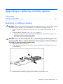
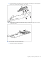
Replacing the cache module or controller
CAUTION: Electrostatic discharge can damage electronic components. Be sure you are properly grounded
before beginning this procedure. For more information, see "Electrostatic Discharge (on page 37)."
1.
Close all applications, and then power down the server. This procedure flushes all data from the
cache.
2.
Observe the BBWC Status LED ("Battery pack LEDs" on page 35).
•
If the LED is blinking every 2 seconds, data is still trapped in the cache. Restore system power,
and repeat the previous steps in this procedure.
•
If the LED is not lit, proceed with the next step.
WARNING: There is a risk of explosion, fire, or personal injury if the battery pack is not
properly handled. Refer to "Battery replacement notice (on page 40)" before installing or
removing any item that contains a battery pack.
3.
Remove the controller from the server.
Upgrading or replacing controller options 22
4.
Pull the flanges on the battery clip outward (1), and then swivel the clip 180 degrees so that it rests
on the batteries (2).
5.
Swivel the latches on the DIMM connector outward (1).
6.
Slide the battery assembly and the cache module off the controller board (2).
The procedure at this point depends on whether you are replacing the controller or the cache
module.
7.
•
If you are replacing the controller, go directly to the next step.
•
If you are replacing the cache module, pull it out of the battery assembly, install the new cache
module in its place, and go to the next step.
Install the cache module and batteries on the controller board.
a. Hold the controller board near the DIMM connector and at the top and right edges to minimize
bending of the board.
Upgrading or replacing controller options 23
b. Position the batteries so that the pegs A on the underside of each battery are in the appropriate
holes B on the controller board and pegs C are in slots D.
c. Slide the batteries toward the board bracket until the connectors on the cache module are firmly
seated in the DIMM connector. (When the cache module is correctly seated, the gold contacts on
the cache module are completely hidden within the DIMM connector.)
8.
Secure the battery clip to the controller board.
a. Swivel the clip over the cache module (1).
Upgrading or replacing controller options 24
b. Push the clip firmly at both ends (2) until it clicks into place under the controller board.
9.
Reinstall the controller in the server.
Upgrading or replacing controller options 25
Replacing, moving, or adding hard drives
In this section
Identifying the status of a hard drive ......................................................................................................... 26
Recognizing hard drive failure................................................................................................................. 27
Replacing hard drives ............................................................................................................................. 29
Moving drives and arrays ....................................................................................................................... 32
Adding drives ........................................................................................................................................ 32
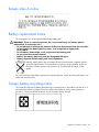
Identifying the status of a hard drive
When a drive is configured as a part of an array and connected to a powered-up controller, the
condition of the drive can be determined from the illumination pattern of the hard drive status lights (LEDs).
Item
Description
1
Fault/UID LED (amber/blue)
2
Online LED (green)
Online/activity LED Fault/UID LED
(green)
(amber/blue)
Interpretation
On, off, or flashing Alternating amber
and blue
The drive has failed, or a predictive failure alert has been
received for this drive; it also has been selected by a
management application.
On, off, or flashing Steadily blue
The drive is operating normally, and it has been selected by a
management application.
On
On
Amber, flashing
regularly (1 Hz)
A predictive failure alert has been received for this drive.
Off
The drive is online, but it is not active currently.
Replace the drive as soon as possible.
Replacing, moving, or adding hard drives 26
Online/activity LED Fault/UID LED
(green)
(amber/blue)
Interpretation
Flashing regularly
(1 Hz)
Do not remove the drive. Removing a drive may
terminate the current operation and cause data loss.
Amber, flashing
regularly (1 Hz)
The drive is part of an array that is undergoing capacity
expansion or stripe migration, but a predictive failure alert has
been received for this drive. To minimize the risk of data loss, do
not replace the drive until the expansion or migration is
complete.
Flashing regularly
(1 Hz)
Off
Do not remove the drive. Removing a drive may
terminate the current operation and cause data loss.
The drive is rebuilding, or it is part of an array that is undergoing
capacity expansion or stripe migration.
Flashing irregularly Amber, flashing
regularly (1 Hz)
The drive is active, but a predictive failure alert has been
received for this drive. Replace the drive as soon as possible.
Flashing irregularly Off
The drive is active, and it is operating normally.
Off
Steadily amber
A critical fault condition has been identified for this drive, and
the controller has placed it offline. Replace the drive as soon as
possible.
Off
Amber, flashing
regularly (1 Hz)
A predictive failure alert has been received for this drive.
Replace the drive as soon as possible.
Off
Off
The drive is offline, a spare, or not configured as part of an
array.
Recognizing hard drive failure
A steadily glowing Fault LED indicates that that drive has failed. Other means by which hard drive failure
is revealed are:
•
The amber LED on the front of a storage system illuminates if failed drives are inside. (However, this
LED also illuminates when other problems occur, such as when a fan fails, a redundant power supply
fails, or the system overheats.)
•
A POST message lists failed drives whenever the system is restarted, as long as the controller detects
at least one functional drive.
•
ACU represents failed drives with a distinctive icon.
•
Systems Insight Manager can detect failed drives remotely across a network. (For more information
about Systems Insight Manager, refer to the documentation on the Management CD.)
•
ADU lists all failed drives.
For additional information about diagnosing hard drive problems, refer to the HP Servers Troubleshooting
Guide.
CAUTION: Sometimes, a drive that has previously been failed by the controller may seem to be
operational after the system is power-cycled or (for a hot-pluggable drive) after the drive has been removed
and reinserted. However, continued use of such marginal drives may eventually result in data loss. Replace
the marginal drive as soon as possible.
Replacing, moving, or adding hard drives 27
Effects of a hard drive failure
When a hard drive fails, all logical drives that are in the same array are affected. Each logical drive in
an array might be using a different fault-tolerance method, so each logical drive can be affected
differently.
•
RAID 0 configurations cannot tolerate drive failure. If any physical drive in the array fails, all nonfault-tolerant (RAID 0) logical drives in the same array will also fail.
•
RAID 1+0 configurations can tolerate multiple drive failures as long as no failed drives are mirrored
to one another.
•
RAID 5 configurations can tolerate one drive failure.
•
RAID 6 (ADG) configurations can tolerate the simultaneous failure of two drives.
Compromised fault tolerance
If more hard drives fail than the fault-tolerance method allows, fault tolerance is compromised, and the
logical drive fails. In this case, all requests from the operating system are rejected with unrecoverable
errors. You are likely to lose data, although it can sometimes be recovered (refer to "Recovering from
compromised fault tolerance" on page 28).
One example of a situation in which compromised fault tolerance may occur is when a drive in an array
fails while another drive in the array is being rebuilt. If the array has no online spare, any logical drives
in this array that are configured with RAID 5 fault tolerance will fail.
Compromised fault tolerance can also be caused by non-drive problems, such as a faulty cable or
temporary power loss to a storage system. In such cases, you do not need to replace the physical drives.
However, you may still have lost data, especially if the system was busy at the time that the problem
occurred.
Recovering from compromised fault tolerance
If fault tolerance is compromised, inserting replacement drives does not improve the condition of the
logical volume. Instead, if the screen displays unrecoverable error messages, perform the following
procedure to recover data:
1.
Power down the entire system, and then power it back up. In some cases, a marginal drive will work
again for long enough to enable you to make copies of important files.
If a 1779 POST message is displayed, press the F2 key to re-enable the logical volumes. Remember
that data loss has probably occurred and any data on the logical volume is suspect.
2.
Make copies of important data, if possible.
3.
Replace any failed drives.
4.
After you have replaced the failed drives, fault tolerance may again be compromised. If so, cycle the
power again. If the 1779 POST message is displayed:
a. Press the F2 key to re-enable the logical drives.
b. Recreate the partitions.
c. Restore all data from backup.
To minimize the risk of data loss that is caused by compromised fault tolerance, make frequent backups of
all logical volumes.
Replacing, moving, or adding hard drives 28
Replacing hard drives
The most common reason for replacing a hard drive is that it has failed. However, another reason is to
gradually increase the storage capacity of the entire system.
If you insert a hot-pluggable drive into a drive bay while the system power is on, all disk activity in the
array pauses for a second or two while the new drive is spinning up. When the drive has achieved its
normal spin rate, data recovery to the replacement drive begins automatically (as indicated by the
blinking Online/Activity LED on the replacement drive) if the array is in a fault-tolerant configuration.
If you replace a drive belonging to a fault-tolerant configuration while the system power is off, a POST
message appears when the system is next powered up. This message prompts you to press the F1 key to
start automatic data recovery. If you do not enable automatic data recovery, the logical volume remains
in a ready-to-recover condition and the same POST message appears whenever the system is restarted.
Factors to consider before replacing hard drives
Before replacing a degraded drive:
•
Open Systems Insight Manager, and inspect the Error Counter window for each physical drive in the
same array to confirm that no other drives have any errors. (For details, refer to the Systems Insight
Manager documentation on the Management CD.)
•
Be sure that the array has a current, valid backup.
•
Confirm that the replacement drive is of the same type (SAS or SATA) as the degraded drive.
•
Use replacement drives that have a capacity at least as great as that of the smallest drive in the
array. The controller immediately fails drives that have insufficient capacity.
In systems that use external data storage, be sure that the server is the first unit to be powered down and
the last to be powered back up. Taking this precaution ensures that the system does not erroneously mark
the drives as failed when the server is powered up.
To minimize the likelihood of fatal system errors, take these precautions when removing failed drives:
•
Do not remove a degraded drive if any other drive in the array is offline (the Online/Activity LED is
off). In this situation, no other drive in the array can be removed without data loss.
The following cases are exceptions:
•
•
When RAID 1+0 is used, drives are mirrored in pairs. Several drives can be in a failed condition
simultaneously (and they can all be replaced simultaneously) without data loss, as long as no two
failed drives belong to the same mirrored pair.
•
When RAID 6 (ADG) is used, two drives can fail simultaneously (and be replaced simultaneously)
without data loss.
•
If the offline drive is a spare, the degraded drive can be replaced.
Do not remove a second drive from an array until the first failed or missing drive has been replaced
and the rebuild process is complete. (The rebuild is complete when the Online/Activity LED on the
front of the drive stops blinking.)
The following cases are exceptions:
•
In RAID 6 (ADG) configurations, any two drives in the array can be replaced simultaneously.
•
In RAID 1+0 configurations, any drives that are not mirrored to other removed or failed drives
can be simultaneously replaced offline without data loss.
Automatic data recovery (rebuild)
When you replace a hard drive in an array, the controller uses the fault-tolerance information on the
remaining drives in the array to reconstruct the missing data (the data that was originally on the replaced
Replacing, moving, or adding hard drives 29
drive) and write it to the replacement drive. This process is called automatic data recovery, or rebuild. If
fault tolerance is compromised, this data cannot be reconstructed and is likely to be permanently lost.
If another drive in the array fails while fault tolerance is unavailable during rebuild, a fatal system error
can occur, and all data on the array is then lost. In exceptional cases, however, failure of another drive
need not lead to a fatal system error. These exceptions include:
•
Failure after activation of a spare drive
•
Failure of a drive that is not mirrored to any other failed drives (in a RAID 1+0 configuration)
•
Failure of a second drive in a RAID 6 (ADG) configuration
Time required for a rebuild
The time required for a rebuild varies considerably, depending on several factors:
•
The priority that the rebuild is given over normal I/O operations (you can change the priority setting
by using ACU)
•
The amount of I/O activity during the rebuild operation
•
The rotational speed of the hard drives
•
The availability of drive cache
•
The brand, model, and age of the drives
•
The amount of unused capacity on the drives
•
For RAID 5 and RAID 6 (ADG), the number of drives in the array
Allow approximately 15 minutes per gigabyte for the rebuild process to be completed. This figure is
conservative; the actual time required is usually less than this.
System performance is affected during the rebuild, and the system is unprotected against further drive
failure until the rebuild has finished. Therefore, replace drives during periods of low activity when
possible.
When automatic data recovery has finished, the Online/Activity LED of the replacement drive stops
blinking steadily at 1 Hz and begins to either glow steadily (if the drive is inactive) or flash irregularly (if
the drive is active).
CAUTION: If the Online/Activity LED on the replacement drive does not light up while the corresponding
LEDs on other drives in the array are active, the rebuild process has abnormally terminated. The amber Fault
LED of one or more drives might also be illuminated. Refer to "Abnormal termination of a rebuild (on page
30)" to determine what action you must take.
Abnormal termination of a rebuild
If the Online/Activity LED on the replacement drive permanently ceases to be illuminated even while other
drives in the array are active, the rebuild process has abnormally terminated. The following table
indicates the three possible causes of abnormal termination of a rebuild.
Observation
Cause of rebuild termination
None of the drives in the array have
an illuminated amber Fault LED.
One of the drives in the array has
experienced an uncorrectable read error.
The replacement drive has an
illuminated amber Fault LED.
The replacement drive has failed.
One of the other drives in the array
has an illuminated amber Fault LED.
The drive with the illuminated Fault LED has
now failed.
Each of these situations requires a different remedial action.
Case 1: An uncorrectable read error has occurred.
Replacing, moving, or adding hard drives 30
1.
Back up as much data as possible from the logical drive.
CAUTION: Do not remove the drive that has the media error. Doing so causes the logical drive to fail.
2.
Restore data from backup. Writing data to the location of the unreadable sector often eliminates the
error.
3.
Remove and reinsert the replacement drive. This action restarts the rebuild process.
If the rebuild process still terminates abnormally:
1.
Delete and recreate the logical drive.
2.
Restore data from backup.
Case 2: The replacement drive has failed.
Verify that the replacement drive is of the correct capacity and is a supported model. If these factors are
not the cause of the problem, use a different drive as the replacement.
Case 3: Another drive in the array has failed.
A drive that has recently failed can sometimes be made temporarily operational again by cycling the
server power.
1.
Power down the server.
2.
Remove the replacement physical drive (the one undergoing a rebuild), and reinstall the drive that it
is replacing.
3.
Power up the server.
If the newly failed drive seems to be operational again:
1.
Back up any unsaved data.
2.
Remove the drive that was originally to be replaced, and reinsert the replacement physical drive. The
rebuild process automatically restarts.
3.
When the rebuild process has finished, replace the newly failed drive.
However, if the newly failed drive has not recovered:
1.
Remove the drive that was originally to be replaced, and reinsert the replacement physical drive.
2.
Replace the newly failed drive.
3.
Restore data from backup.
Upgrading hard drive capacity
You can increase the storage capacity on a system even if there are no available drive bays by swapping
drives one at a time for higher capacity drives. This method is viable as long as a fault-tolerance method
is running.
CAUTION: Because it can take up to 15 minutes per gigabyte to rebuild the data in the new configuration,
the system is unprotected against drive failure for many hours while a given drive is upgraded. Perform drive
capacity upgrades only during periods of minimal system activity.
To upgrade hard drive capacity:
1.
Back up all data.
2.
Replace any drive. The data on the new drive is re-created from redundant information on the
remaining drives.
CAUTION: Do not replace any other drive until data rebuild on this drive is complete.
When data rebuild on the new drive is complete, the Online/Activity LED stops flashing steadily and
either flashes irregularly or glows steadily.
Replacing, moving, or adding hard drives 31
3.
Repeat the previous step for the other drives in the array, one at a time.
When you have replaced all drives, you can use the extra capacity to either create new logical drives or
extend existing logical drives. For more information about these procedures, refer to the HP Array
Configuration Utility User Guide.
Moving drives and arrays
You can move drives to other ID positions on the same array controller. You can also move a complete
array from one controller to another, even if the controllers are on different servers.
Before you move drives, the following conditions must be met:
•
The server must be powered down.
•
If moving the drives to a different server, the new server must have enough empty bays to
accommodate all the drives simultaneously.
•
The array has no failed or missing drives, and no spare drive in the array is acting as a replacement
for a failed drive.
•
The controller is not running capacity expansion, capacity extension, or RAID or stripe size
migration.
•
The controller is using the latest firmware version (recommended).
If you want to move an array to another controller, all drives in the array must be moved at the same time.
When all the conditions have been met:
1.
Back up all data before removing any drives or changing configuration. This step is required if you
are moving data-containing drives from a controller that does not have a battery-backed cache.
2.
Power down the system.
3.
Move the drives.
4.
Power up the system. If a 1724 POST message appears, drive positions were changed successfully
and the configuration was updated.
If a 1785 (Not Configured) POST message appears:
a. Power down the system immediately to prevent data loss.
b. Return the drives to their original locations.
c. Restore the data from backup, if necessary.
5.
Verify the new drive configuration by running ORCA or ACU ("Configuring an array" on page 13).
Adding drives
You can add hard drives to a system at any time, as long as you do not exceed the maximum number of
drives that the controller supports. You can then either build a new array from the added drives or use the
extra storage capacity to expand the capacity of an existing array.
To perform an array capacity expansion, use ACU. If the system is using hot-pluggable drives, you can
expand array capacity without shutting down the operating system (that is, with the server online) if ACU
is running in the same environment as the normal server applications. (For more information, refer to the
HP Array Configuration Utility User Guide.)
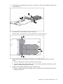
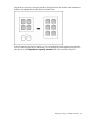
The expansion process is illustrated in the following figure, in which the original array (containing data) is
shown with a dashed border and the newly added drives (containing no data) are shown unshaded. The
array controller adds the new drives to the array and redistributes the original logical drives over the
enlarged array one logical drive at a time. This process liberates some storage capacity on each of the
Replacing, moving, or adding hard drives 32
physical drives in the array. During this procedure, the logical drives each keep the same fault-tolerance
method in the enlarged array that they had in the smaller array.
When the expansion process has finished, you can use the liberated storage capacity on the enlarged
array to create new logical drives. Alternatively, you can enlarge one of the original logical drives. This
latter process is called logical drive capacity extension and is also carried out using ACU.
Replacing, moving, or adding hard drives 33
Diagnosing array problems
In this section
Controller board runtime LEDs.................................................................................................................. 34
Battery pack LEDs................................................................................................................................... 35
Diagnostic tools ..................................................................................................................................... 36
Controller board runtime LEDs
Immediately after the server is powered up, the controller runtime LEDs illuminate briefly in a
predetermined pattern as part of the POST sequence. At all other times during server operation, the
illumination pattern of the runtime LEDs indicates the status of the controller, as described in the following
table.
LED ID
Color
LED name and interpretation
1
Green
CR502: Expander Heartbeat LED. This LED flashes every 2 seconds during
normal operation. Abnormal conditions are indicated as follows:
•
If the LED glows steadily, the expander has an internal problem.
•
If the LED flashes twice per second, the NVRAM is corrupt.
In either case, the expander does not function.
2
Amber
CR510: System Error LED.
3
Amber
CR509: Diagnostics Error LED.
4
Amber
CR500: Drive Failure LED. A physical drive connected to the controller has failed.
Check the Fault LED on each drive to determine which drive has failed.
5
Green
CR508: Activity LED for SAS port 4I.
6
Green
CR507: Activity LED for SAS port 3I.
Diagnosing array problems 34
LED ID
Color
LED name and interpretation
7
Green
CR506: Command Outstanding LED. The controller is working on a command
from the host driver.
8
Green
CR505: Controller Heartbeat LED. This LED flashes every 2 seconds to indicate
the controller health.
9
Green
CR504: Gas Pedal LED. This LED, together with item 10, indicates the amount of
controller CPU activity. For details, see the following table.
10
Green
CR503: Idle Task LED. This LED, together with item 9, indicates the amount of
controller CPU activity. For details, see the following table.
Gas pedal LED status
Idle task LED status
Controller CPU activity level
Off
Blinking
0–25%
Blinking
Off
25–50%
On steadily
Off
50–75%
On steadily
On steadily
75–100%
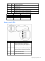
Battery pack LEDs
Item ID
Color
Description
1
Green
System Power LED. This LED glows steadily when the
system is powered up and 12 V system power is
available. This power supply is used to maintain the
battery charge and provide supplementary power to the
cache microcontroller.
2
Green
Auxiliary Power LED. This LED glows steadily when 3.3V
auxiliary voltage is detected. The auxiliary voltage is used
to preserve BBWC data and is available any time that the
system power cords are connected to a power supply.
3
Amber
Battery Health LED. To interpret the illumination patterns of
this LED, see the following table.
4
Green
BBWC Status LED. To interpret the illumination patterns of
this LED, see the following table.
Diagnosing array problems 35
LED3 pattern
LED4 pattern
Interpretation
—
One blink every
two seconds
The system is powered down, and the cache contains data that has
not yet been written to the drives. Restore system power as soon as
possible to prevent data loss.
Data preservation time is extended any time that 3.3 V auxiliary
power is available, as indicated by LED 2. In the absence of
auxiliary power, battery power alone preserves the data. A fullycharged battery can normally preserve data for at least two days.
The battery lifetime also depends on the cache module size. For
further information, refer to the controller QuickSpecs on the HP
website (http://www.hp.com).
—
Double blink,
then pause
The cache microcontroller is waiting for the host controller to
communicate.
—
One blink per
second
The battery pack is below the minimum charge level and is being
charged. Features that require a battery (such as write cache,
capacity expansion, stripe size migration, and RAID migration) are
temporarily unavailable until charging is complete. The recharge
process takes between 15 minutes and two hours, depending on the
initial capacity of the battery.
—
Steady glow
The battery pack is fully charged, and posted write data is stored in
the cache.
—
Off
The battery pack is fully charged, and there is no posted write data
in the cache.
One blink per
second
One blink per
second
An alternating green and amber blink pattern indicates that the
cache microcontroller is executing from within its boot loader and
receiving new flash code from the host controller.
Steady glow
—
There is a short circuit across the battery terminals or within the
battery pack. BBWC features are disabled until the battery pack is
replaced. The life expectancy of a battery pack is typically more
than three years.
One blink per
second
—
There is an open circuit across the battery terminals or within the
battery pack. BBWC features are disabled until the battery pack is
replaced. The life expectancy of a battery pack is typically more
than three years.
Diagnostic tools
Several diagnostic tools provide feedback about problems with arrays. The most important are:
•
ADU
This utility is a Windows®-based diagnostic tool that sends an email to HP Support when it detects
any problems with the controllers and attached storage in a system.
You can install ADU from the Smart Setup media. When installation is complete, run ADU by clicking
Start and selecting Programs>HP System Tools>HP Array Diagnostic Utility.
The meanings of the various ADU error messages are provided in the HP Servers Troubleshooting
Guide.
•
POST messages
Smart Array controllers produce diagnostic error messages at reboot. Many of these POST messages
are self-explanatory and suggest corrective actions. For more information about POST messages,
refer to the HP Servers Troubleshooting Guide.
Diagnosing array problems 36
Electrostatic discharge
In this section
Preventing electrostatic discharge............................................................................................................. 37
Grounding methods to prevent electrostatic discharge ................................................................................ 37
Preventing electrostatic discharge
To prevent damaging the system, be aware of the precautions you need to follow when setting up the
system or handling parts. A discharge of static electricity from a finger or other conductor may damage
system boards or other static-sensitive devices. This type of damage may reduce the life expectancy of the
device.
To prevent electrostatic damage:
•
Avoid hand contact by transporting and storing products in static-safe containers.
•
Keep electrostatic-sensitive parts in their containers until they arrive at static-free workstations.
•
Place parts on a grounded surface before removing them from their containers.
•
Avoid touching pins, leads, or circuitry.
•
Always be properly grounded when touching a static-sensitive component or assembly.
Grounding methods to prevent electrostatic discharge
Several methods are used for grounding. Use one or more of the following methods when handling or
installing electrostatic-sensitive parts:
•
Use a wrist strap connected by a ground cord to a grounded workstation or computer chassis. Wrist
straps are flexible straps with a minimum of 1 megohm ±10 percent resistance in the ground cords.
To provide proper ground, wear the strap snug against the skin.
•
Use heel straps, toe straps, or boot straps at standing workstations. Wear the straps on both feet
when standing on conductive floors or dissipating floor mats.
•
Use conductive field service tools.
•
Use a portable field service kit with a folding static-dissipating work mat.
If you do not have any of the suggested equipment for proper grounding, have an authorized reseller
install the part.
For more information on static electricity or assistance with product installation, contact an authorized
reseller.
Electrostatic discharge 37
Regulatory compliance notices
In this section
Federal Communications Commission notice ............................................................................................. 38
Modifications......................................................................................................................................... 38
Cables .................................................................................................................................................. 38
Canadian notice .................................................................................................................................... 38
European Union regulatory notice ............................................................................................................ 39
BSMI notice ........................................................................................................................................... 39
Japanese class A notice .......................................................................................................................... 39
Korean class A notice ............................................................................................................................. 40
Battery replacement notice ...................................................................................................................... 40
Taiwan battery recycling notice ............................................................................................................... 40
Federal Communications Commission notice
This equipment has been tested and found to comply with the limits for a Class A digital device, pursuant
to Part 15 of the FCC Rules. These limits are designed to provide reasonable protection against harmful
interference when the equipment is operated in a commercial environment. This equipment generates,
uses, and can radiate radio frequency energy and, if not installed and used in accordance with the
instructions, may cause harmful interference to radio communications. Operation of this equipment in a
residential area is likely to cause harmful interference, in which case the user will be required to correct
the interference at personal expense.
Modifications
The FCC requires the user to be notified that any changes or modifications made to this device that are
not expressly approved by Hewlett-Packard Company may void the user’s authority to operate the
equipment.
Cables
Connections to this device must be made with shielded cables with metallic RFI/EMI connector hoods in
order to maintain compliance with FCC Rules and Regulations.
Canadian notice
This Class A digital apparatus meets all requirements of the Canadian Interference-Causing Equipment
Regulations.
Cet appareil numérique de la classe A respecte toutes les exigences du Règlement sur le matériel
brouilleur du Canada.
Regulatory compliance notices
38
European Union regulatory notice
This product complies with the following EU Directives:
•
Low Voltage Directive 73/23/EEC
•
EMC Directive 89/336/EEC
Compliance with these directives implies conformity to applicable harmonized European standards
(European Norms) which are listed on the EU Declaration of Conformity issued by Hewlett-Packard for this
product or product family.
This compliance is indicated by the following conformity marking placed on the product:
This marking is valid for non-Telecom products and EU harmonized Telecom products (e.g. Bluetooth).
This marking is valid for EU non-harmonized Telecom products.
*Notified body number (used only if applicable—refer to the product label)
Hewlett-Packard GmbH, HQ-TRE, Herrenberger Strasse 140, 71034 Boeblingen, Germany
BSMI notice
Japanese class A notice
Regulatory compliance notices
39
Korean class A notice
Battery replacement notice
This component uses a nickel metal hydride (NiMH) battery pack.
WARNING: There is a risk of explosion, fire, or personal injury if a battery pack is
mishandled. To reduce this risk:
• Do not attempt to recharge the batteries if they are disconnected from the controller.
• Do not expose the battery pack to water, or to temperatures higher than
60°C (140°F).
• Do not abuse, disassemble, crush, or puncture the battery pack.
• Do not short the external contacts.
• Replace the battery pack only with the designated HP spare.
• Battery disposal should comply with local regulations.
Batteries, battery packs, and accumulators should not be disposed of together with the
general household waste. To forward them to recycling or proper disposal, please use
the public collection system or return them to HP, an authorized HP Partner, or their
agents.
For more information about battery replacement or proper disposal, contact an authorized reseller or an
authorized service provider.
Taiwan battery recycling notice
The Taiwan EPA requires dry battery manufacturing or importing firms in accordance with Article 15 of
the Waste Disposal Act to indicate the recovery marks on the batteries used in sales, giveaway or
promotion. Contact a qualified Taiwanese recycler for proper battery disposal.
Regulatory compliance notices
40
Acronyms and abbreviations
ACU
Array Configuration Utility
ADG
Advanced Data Guarding (also known as RAID 6)
ADU
Array Diagnostics Utility
BBWC
battery-backed write cache
DIMM
dual inline memory module
EBSU
EFI-based setup utility
EFI
extensible firmware interface
LED
light-emitting diode
ORCA
Option ROM Configuration for Arrays
PCIe
peripheral component interconnect express
POST
Power-On Self Test
RBSU
ROM-Based Setup Utility
Acronyms and abbreviations
41
SA
Smart Array
Acronyms and abbreviations
42
Index
A
E
ACU (Array Configuration Utility) 13, 15
adding drives 32
Array Configuration Utility (ACU) 13
array controller installation overview 7
array expansion 32
array, configuring 13
array, moving 32
automatic data recovery (rebuild) 29
electrostatic discharge 37
environmental requirements 5
error messages 27
European Union notice 39
Event Notification service 16
expanding an array 32
extending logical drive capacity 32
B
batteries, replacing 18
battery pack LEDs 35
battery replacement notice 40
board components 5
BSMI notice 39
C
cable part numbers 11
cables 38
Canadian notice 38
compatibility of parallel SCSI drives 10
compromised fault tolerance 28
configuring an array 13
connectors 5
controller board, features of 5
controller board, installing 7, 9
controller installation, overview of 7
controller LEDs 34
D
data recovery 28, 29
data transfer rate 5
device drivers, installing 16
drive capacity, upgrading 31
drive failure, detecting 27
drive LEDs 26
drivers 16
drives, adding 32
drives, moving 32
F
failure, hard drive 27
fault tolerance, compromised 28
Federal Communications Commission (FCC)
notice 38
firmware, updating 12
G
grounding methods 37
H
hard
hard
hard
hard
hard
hard
hard
hard
drive LEDs 26
drive, failure of 28
drive, replacing 29
drives, adding 32
drives, determining status of 26
drives, installing 10
drives, maximum number of 5
drives, moving 32
I
installation overview 7
J
Japanese notice 39
K
Korean notices 40
Index 43
L
T
LEDs, battery pack 35
LEDs, controller 34
LEDs, hard drive 26
logical drive capacity extension 32
logical drive, creating 13
logical drives, maximum number of 5
Taiwan battery recycling notice 40
temperature requirements 5
troubleshooting 36
M
U
updating the firmware 12
upgrading drive capacity 31
Management Agents, updating 16
moving an array 32
O
Option ROM Configuration for Arrays (ORCA) 13
ORCA (Option ROM Configuration for Arrays) 13,
14
overview of installation process 7
P
parallel SCSI drives, compatibility of 10
physical drives, maximum number of 5
POST error messages 27
power requirements 5
R
rebuild, abnormal termination of 30
rebuild, description 29
rebuild, time required 30
regulatory compliance notices 38, 39, 40
replacing hard drives 26
replacing the batteries 18
replacing the cache module 22
replacing the controller 22
ROM, updating 12
runtime LEDs 34
S
spares, battery pack, part number 5
spares, cable part numbers 11
specifications, controller 5
static electricity 37
status lights, battery pack 35
status lights, controller 34
status lights, hard drive 26
storage capacity, increasing 31
storage devices, connecting 10
summary of installation procedure 7
Index 44