1
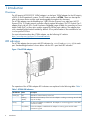
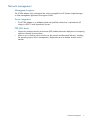
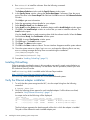
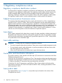
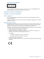
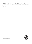
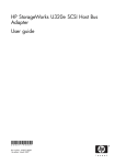
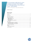
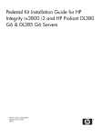
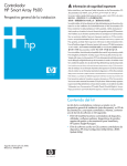
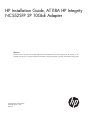
HP Installation Guide, AT118A HP Integrity
NC552SFP 2P 10GbE Adapter
Abstract
This document is for the person who installs, administers, and troubleshoots servers and storage systems. HP assumes you are
qualified in the servicing of computer equipment and trained in recognizing hazards in products with hazardous energy levels.
HP Part Number: AT118-90002
Published: February 2012
Edition: 2
© Copyright 2011, 2012 Hewlett-Packard Development Company, L.P.
The information contained herein is subject to change without notice. The only warranties for HP products and services are set forth in the express
warranty statements accompanying such products and services. Nothing herein should be construed as constituting an additional warranty. HP shall
not be liable for technical or editorial errors or omissions contained herein.
Contents
1 Introduction...............................................................................................4
Overview................................................................................................................................4
LED indicators..........................................................................................................................4
Network management...............................................................................................................5
2 Installing an adapter...................................................................................6
Preventing electrostatic discharge................................................................................................6
Installing an adapter in a server.................................................................................................6
Installing a low profile bracket....................................................................................................7
Connecting other devices...........................................................................................................7
3 Installing the HP-UX operating system components...........................................8
HP-UX operating system.............................................................................................................8
Prerequisites.............................................................................................................................8
Important Ethernet patches and updates......................................................................................9
Update the adapter firmware.....................................................................................................9
Installing driver software............................................................................................................9
Installing OnlineDiag..............................................................................................................10
Verify the Ethernet adapter installation.......................................................................................10
Verify Ethernet connectivity.......................................................................................................11
Alternate website for downloading files.....................................................................................11
4 Specifications...........................................................................................12
Cable specifications................................................................................................................12
General specifications.............................................................................................................12
Compliance...........................................................................................................................12
Power and environmental specifications.....................................................................................13
5 Regulatory compliance notices...................................................................14
Regulatory compliance identification numbers............................................................................14
Federal Communications Commission notice..............................................................................14
Laser device...........................................................................................................................14
Laser safety warning...............................................................................................................14
Certification and classification information.................................................................................14
Laser product label.................................................................................................................14
International notices and statements..........................................................................................15
Canadian notice (avis Canadien).............................................................................................15
Class A equipment.............................................................................................................15
European Union notice............................................................................................................15
BSMI notice...........................................................................................................................16
Japanese notice......................................................................................................................16
Korean notices.......................................................................................................................16
6 Electrostatic Discharge..............................................................................17
Electrostatic Discharge.............................................................................................................17
Grounding Methods................................................................................................................17
7 HP Contact information.............................................................................18
HP contact information............................................................................................................18
8 Acronyms and abbreviations......................................................................19
Acronyms and abbreviations....................................................................................................19
Index.........................................................................................................20
Contents
3
1 Introduction
Overview
The HP Integrity NC552SFP 2P 10GbE adapter is a dual port 10GbE adapter for the HP Integrity
rx2800 i2 and Superdome2 systems. The HP Product number is AT118A. These two descriptions
refer to the same device and are used interchangeably throughout this document.
The AT118A adapter uses the BladeEngines 3 (BE3) Emulex chip and is an eight lane (x8) PCI
Express (PCIe) 10 Gigabit network controller offering optimal throughput. This PCI Express Gen 2
adapter ships with two SFP+ (Small Form-factor Pluggable) cages suitable for connecting to Direct
Attach Cable (DAC) or fiber optic modules supporting SR fiber optic cabling. The adapter ships
with a standard height bracket installed by default. A low profile bracket is also available for use
in a low profile PCIe slot.
For more information about the AT118A adapter, see the following HP website:
http://www.hp.com/go/hpux-11iv3-iocards-manuals
LED indicators
The AT118A adapter has two ports with LED indicators for Link (L) and Activity (A) for each
port. Standard-height bracket is shown below with the SFP+ ports and LED indicators.
Figure 1 The AT118A adapter
The operation of the AT118A adapter LED indicators are explained in the following table: Table 1
Table 1 AT118A LED Indicators
LED Indicator
Status
Description
Activity (A)
Off
Indicates no network activity on the link.
Flashing
(Green)
Indicates network activity on the link. The adapter is sending or receiving network data
at up to 10 Gbps.
Off
No link to the adapter is established. The adapter is not receiving power or the cable
connection is faulty.
On (Yellow)
Link to the adapter is established. The adapter is receiving power and the cable
connection is good.
Link (L)
4
Introduction
Network management
Management support
The AT118A adapter ships with agents that can be managed from HP Systems Insight Manager
or other management application that support SNMP.
Server integration
•
The AT118A adapter is a validated, tested and qualified solution that is optimized for HP
Integrity rx2800 i2 and Superdome2 servers.
PXE (LAN boot)
•
Support for pre-boot execution environment (PXE) enables automatic deployment of computing
resources remotely from anywhere.
•
Allows a new or existing server to boot over the network and download software, including
the operating system, from a management/ deployment server at another location on the
network.
Network management
5
2 Installing an adapter
IMPORTANT: See the following chapter before installing the AT118A adapter: “Installing the
HP-UX operating system components” (page 8)
Preventing electrostatic discharge
To prevent damaging the system, be aware of the precautions you need to follow when setting up
the system or handling parts. A discharge of static electricity from a finger or other conductor may
damage system boards or other static-sensitive devices. This type of damage may reduce the life
expectancy of the device.
To prevent electrostatic damage:
•
Avoid hand contact by transporting and storing products in static-safe containers.
•
Keep electrostatic-sensitive parts in their containers until they arrive at static-free workstations.
•
Place parts on a grounded surface before removing them from their containers.
•
Avoid touching pins, leads, or circuitry.
•
Always be properly grounded when touching a static-sensitive component or assembly.
Installing an adapter in a server
See the HP Integrity rx2800 i2 and Superdome server documentation for additional information
on how to safely install a PCI Express card in the server.
NOTE:
A minimum of two Gigabytes (2 GB) of server memory is required per each adapter.
NOTE: Direct Attach Cable (DAC) for copper environments or fiber transceivers and cables for
fiber-optic environments must be purchased separately.
The Online Addition and Replacement feature, OL* for the HP-UX 11i v3 release, enables PCI host
bus adapters to be added or replaced without shutting down and rebooting the system, and without
adversely affecting other system components. The system hardware uses slot-specific power control,
combined with HP-UX operating system support, to enable these features.
Confirm whether OL* is supported on the system in which you plan to install an Ethernet adapter.
See the HP Ethernet System-Driver Support Matrix, at the following website:
http://www.hp.com/go/hpux-11iv3-iocards-manuals
IMPORTANT: Superdome systems are not intended to be maintained by customers. HP recommends
that Superdome systems only be opened by a qualified HP service engineer. Failure to observe
this recommendation can invalidate any support agreement or warranty to which you may be
entitled.
NOTE: The optical port protector is used only to protect the adapter port when it is not in use.
Do not use the protector as a diagnostic tool.
Install all driver software and dependent patches before you install the adapter. For more
information, see “Prerequisites” (page 8)
1. Install all driver software and dependent patches.
2. Shut down the system.
3. If a low profile option slot is to be used, install the low profile bracket onto the adapter.
NOTE:
6
Installing an adapter
See the following procedure “Installing a low profile bracket” (page 7).
4.
5.
6.
Insert the card into the highest-performance PCIe slot available.
Attach all the cables to the adapter.
Do not power on the system until the following section is complete: “Connecting other devices”
(page 7)
Installing a low profile bracket
You may have to install a low profile bracket prior to the product installation. The low profile
bracket replaces the existing standard profile bracket shipped on the product.
1. Using a correctly sized Phillips head screwdriver, carefully remove the two board lock screws
located above and below the SFP+ connectors.
2. Remove the standard profile bracket and place the low profile bracket over the connectors.
Be careful not to damage the connectors or bend the low profile bracket.
3. Reinstall the two Phillips screws.
Connecting other devices
Connecting the network cable
The AT118A has two SFP+ ports. These ports support either of the following:
•
Direct Attached Copper (DAC) cables
•
Optical Modules to be used with fiber optic cables
See Cable specifications for the maximum cable length supported.
To connect the AT118A to the network, complete the following steps:
1. Orient the SFP+ optical module or DAC cable so that the Gold Fingers on the edge of the
circuit board is located closest to the option card circuit board.
2. Install the SFP+ optical module or DAC cable all the way into the SFP+ socket until it clicks
into place and is securely latched.
3. If an optical module is used, remove the protective cover and connect the fiber optic cable.
Installing a low profile bracket
7
3 Installing the HP-UX operating system components
HP-UX operating system
The HP Integrity NC552SFP 2P 10GbE adapter is supported through the HP-UX 11i v3 operating
system.
Prerequisites
Before installing the adapter, follow these steps:
1. The adapter card is supported through the HP Integrity rx2800 i2 and Superdome2 server
platforms. Verify compliance with supported configurations using the HP Ethernet System-Driver
Support Matrix at the following website:
http://www.hp.com/go/hpux-iocards-docs
2.
Ensure that your system meets the following minimum software and firmware requirements:
•
HP Integrity rx2800 i2 — Recipe S26.21, HP-UX B.11.31.1109 or later
•
HP Superdome2 — Minimum Firmware Bundle Required 2.51.102, HP-UX B.11.31.1109
or later
Information for HP Integrity servers is available at the following website:
http://welcome.hp.com/country/us/en/prodserv/servers.html
IMPORTANT: This document contains minimum firmware requirements; HP strongly advises
that you check for the latest versions of firmware that are available for your systems.
1. Go to http://www.hp.com.
2. Locate and click the Support & Drivers link on the main page.
3. Click the button next to Download drivers and software (and firmware).
4. Enter your product name (for example, Superdome 2) or number and click >>.
5. After selecting the correct product, choose the OS or Cross operating system (BIOS,
Firmware, Diagnostics, etc.)
6. Refer to the Release Notes or Installation Instructions to verify the firmware version.
3.
Confirm that the server model and operating system are supported with the AT118A adapter.
Also, determine the required versions for the system firmware, adapter firmware, and UEFI
driver.
For more information, see the HP-UX Ethernet Card Support Matrix at:
www.hp.com/go/integrity-iocards-docs
Support Matrix documents are listed alphabetically in the “General reference” section.
4.
Check the following conditions:
•
Verify that the /usr/bin, /usr/sbin, and /sbin directories are in the
PATH
by entering the following command:
echo $PATH
8
•
Verify you have the Ethernet driver software (included with the OS or application CD or
downloaded).
•
Ensure that cable connections follow these procedures: “Connecting other devices”
(page 7)
•
Cable map (optional)
Installing the HP-UX operating system components
Important Ethernet patches and updates
Review the 10GigEthr-03 (iocxgbe) Ethernet Driver for HP-UX Release Notes located at:
http://www.hp.com/go/hpux-11iv3-iocards-manuals . Search for the latest patch and dependency
requirements.
Install all driver software and dependency patches before you install the adapter.
NOTE:
Patches are available from the Software Depot website:
https://h20392.www2.hp.com/portal/swdepot/index.do
Update the adapter firmware
CAUTION: Updating the adapter firmware is REQUIRED. Ensure that you follow the instructions
detailed in the README.TXT file included with the update package. If you do not update the adapter
firmware, hardware failure will result.
To obtain and install the latest firmware for the adapter, follow these steps:
1. See the following website:
http://www.hp.com/products1/serverconnectivity/adapters/index.html
2.
3.
4.
5.
6.
7.
8.
Using the HP adapter model # as your guide, select your NIC.
In the support section, select the Software & Drivers link.
Select Cross operating system (BIOS, Firmware, Diagnostics, etc.).
Select EFI and FWs for use on Integrity.
Review the installation instructions and release notes on the download page.
Download the firmware.
Follow the procedures supplied with the update package to install the firmware update.
Installing driver software
Use the following instructions if the driver is provided on a CD-ROM. If the driver software is
downloaded, follow the instructions provided with that file.
Ethernet
NOTE: The initial release of the 10GigEthr-03 bundle is available by restricted download
only; please contact your account manager or HP-UX Ambassador for instructions on how to obtain
this bundle.
Future releases of the HP-UX v3 Operating Environment media or Application Release media will
include the bundle, and the bundle will also be made available for unrestricted download on the
Software Depot website.
Install all driver software and dependency patches before you install the adapter. See the
10GigEthr-03 (iocxgbe) Ethernet Driver for HP-UX Release Notes for further details, available at:
http://www.hp.com/go/hpux-11iv3-iocards-manuals
Installing the driver from CD-ROM
Use
1.
2.
3.
the following procedure to load the driver from a CD-ROM:
Log in to the system as root.
Insert the CD into the CD drive.
Mount the CD using the following command:
mount /dev/dsk/<cd_rom_dev_file> /<tmp_mnt>
Important Ethernet patches and updates
9
4.
Run swinstall to install the software. Enter the following command:
/usr/sbin/swinstall
The Software Selection window and the Specify Source window open.
5.
In the Specify Source window, change the Source Host Name if necessary. Enter the mount
point of the drive in the Source Depot Path field and click OK to return to the Software Selection
Window.
Click Help to get more information.
6.
7.
8.
9.
Select the appropriate software bundle for your adapter.
Select Mark for Install from the Actions menu.
Select Install from the Actions menu. Installation begins and the Install Analysis window opens.
Click OK in the Install Analysis window to confirm that you want to install the software. The
Install window opens.
View the Install window to read processing data while the software installs. When the Status
field indicates Ready, the Confirmation window opens
10.
11.
12.
13.
14.
Click OK. A second Confirmation window opens.
Click OK again. The Install window opens.
Click Done. The Note window opens.
Click OK in the Note window to reboot. The user interface disappears and the system reboots.
Once the system returns to a login, log in as root and open the following files to see any
error or warning messages that may have occurred during the installation:
/var/adm/sw/swagent.log
/var/adm/sw/swinstall.log
15. Proceed to “Installing OnlineDiag” (page 10)
Installing OnlineDiag
Failure to properly complete the steps in this procedure may result in erratic system behavior or
system failure and may void the warranty. For assistance with this procedure, contact your local
HP Authorized Service Provider.
Install OnlineDiag, which is available at the Software Depot website:
https://h20392.www2.hp.com/portal/swdepot/index.do
OnlineDiag is also available from the IPF CD for Itanium®-based systems.
Verify the Ethernet adapter installation
1.
To verify that the system recognizes the NIC, view the output listing from the following
command:
# ioscan -kfnC lan
2.
Verify the following drivers appear for each installed adapter. If all the drivers are listed,
proceed to “Verify Ethernet connectivity” (page 11).
An output similar to the following will be displayed:
ioscan -kfnC lan
Class
I H/W Path
Driver S/W State
H/W Type
Description
==========================================================================
lan
4 40/0/0/0/0/0/0 iocxgbe
CLAIMED
INTERFACE
HP AT118A 2p 10GbE PCIe Adapter
lan
5 40/0/0/0/0/0/1 iocxgbe
CLAIMED
INTERFACE
HP AT118A 2p 10GbE PCIe Adapter
The third column represents the hardware path of the slot in which the adapter is installed.
This path will be different for each installed adapter port.
10
Installing the HP-UX operating system components
3.
Observe whether the ioscan output reports the following:
lan 0/3/0/0/0/0 UNCLAIMED UNKNOWN
If reported, HP-UX detected the adapter but the iocxgbe driver is not recognized.
4.
If the correct driver is installed and the adapter is not listed in the ioscan output, contact HP
for assistance.
Verify Ethernet connectivity
Once the HP Ethernet software and hardware are installed and running, use the following steps
to verify connectivity:
1.
Check the state of all Ethernet hardware and interfaces. Enter the ioscan -kfnC lan
command and verify the S/W State is CLAIMED.
If the Ethernet device file has not been created, enter the following commands:
# insf -e
# ioscan -f
2.
Verify link-level connectivity with a remote system on the network you have attached to the
Ethernet adapter by using the nwmgr command in the following format.
nwmgr --diag -A dest=destination_MAC_address -c lanppa
NOTE: When you use nwmgr --diag to check connectivity, ensure that the remote system
is on the same subnet and is an HP-UX-based system.
Alternate website for downloading files
1.
See the following HP website:
http://www.hp.com/#Support
2.
3.
4.
You can click open the Support & Drivers link or enter your adapter product number in the
SEARCH HP.COM field, then click go. For example, type AT094A.
At the next web page, either locate the Software & driver downloads link to continue search
or view the returned listing for your selected product.
Download the drivers, firmware, or documentation as needed.
Verify Ethernet connectivity
11
4 Specifications
Cable specifications
Table 2 Cable specifications
SFP+ module
type
10GBASE-SR
(short range)
Optical
Module
10GBASE-CR
with Direct
Attached
Copper (DAC)
cable
Cable grade
Minimum
modal
bandwidth
(MHz-km)
Maximum cable
length (meters)
62.5
(“FDDI”)
160
26
62.5
OM1
200
33
400
66
Wavelength
Cable
(nm), type of
connector type cable
Core size
(microns µm)
LC
SFP+
850,
Multi-Mode
Fiber (MMF)
N/A, Twin
Axial Copper
50
50
OM2
500
82
50
OM3
2000
300
N/A
7
24 to 28 AWG, N/A
depending on
length and
manufacturer
General specifications
Table 3 General specifications
General specifications
Value
Form factor
Low profile. Card is available with standard height and low profile brackets.
Dimensions (H x L x W) — standard 10.67 cm x 16.7 cm x 6.8 cm (4.2 in x 6.6 in x 2.7 in)
height bracket
low profile bracket
6.9 cm x 16.7 cm x 6.8 cm (2.7 in x 6.6 in x 2.7 in)
Weight
0.181 kg (0.4 lb)
Data rate
Two fully independent 2/4/8 Gbps FC links delivering up to 1600MB/s total
bandwidth per channel
Max transfer rate
10000 Mbps
Compliance
Table 4 Compliance
Compliance
Standard
IEEE
IEEE802.3x, IEEE802.3ad, IEEE802.1p, IEEE802.1q, IEEE802.3az,
IEEE802.3ae, IEEE802.3ap, IEEE802.1qau
Safety
UL Mark (US and Canada)
EN 60950
Other
PCIe v2.0
RoHS 6 of 6
IPv4, IPv6
CE
SFF-8431- 10 Gigabit Small Form Factor Pluggable Module “SFP+”
SNMP
12
Specifications
Table 4 Compliance (continued)
Compliance
Standard
IPv4/IPv6 TCP, UDP checksum Offload
IPv4/IPv6 TCP, Large Send Offload
IPv4/IPv6 TCP, Large Receive Offload
Jumbo Frames up to 9000 Bytes
Power and environmental specifications
Table 5 Power and environmental specifications
Power and environmental specifications
Value
Operating
Temperature 0° to 55° C (32° to 131° F)
Humidity 15 to 80% relative humidity (RH), non-condensing
Non-operating
Temperature -40° to 70° C (-40° to 158° F)
Humidity 10 to 90% relative humidity (RH), non-condensing
Power
9.4 Watts typical, 10.5 Watts maximum
Power and environmental specifications
13
5 Regulatory compliance notices
Regulatory compliance identification numbers
For the purpose of regulatory compliance certifications and identification, this product has been
assigned a unique regulatory model number. The regulatory model number can be found on the
product nameplate label, along with all required approval markings and information. When
requesting compliance information for this product, always refer to this regulatory model number.
The regulatory model number is not the marketing name or model number of the product.
Federal Communications Commission notice
This equipment has been tested and found to comply with the limits for a Class A digital device,
pursuant to Part 15 of the FCC Rules. These limits are designed to provide reasonable protection
against harmful interference when the equipment is operated in a commercial environment. This
equipment generates, uses, and can radiate radio frequency energy and, if not installed and used
in accordance with the instructions, may cause harmful interference to radio communications.
Operation of this equipment in a residential area is likely to cause harmful interference, in which
case the user will be required to correct the interference at personal expense.
Laser device
All HP systems equipped with a laser device comply with safety standards, including International
Electrotechnical Commission (IEC) 825. With specific regard to the laser, the equipment complies
with laser product performance standards set by government agencies as a Class 1 laser product.
The product does not emit hazardous light.
Laser safety warning
WARNING!
To reduce the risk of exposure to hazardous radiation:
•
Do not try to open the laser device enclosure. There are no user-serviceable components inside.
•
Do not operate controls, make adjustments, or perform procedures to the laser device other
than those specified in this document.
•
Allow only HP-authorized service technicians to repair the laser device.
Certification and classification information
This product contains a laser internal to the fiber optic (FO) transceiver for connection to the Fibre
Channel communications port.
In the USA, the FO transceiver is certified as a Class 1 laser product conforming to the requirements
contained in the Department of Health and Human Services (DHHS) regulation 21 CFR, Subchapter
J. A label on the plastic FO transceiver housing indicates the certification.
Outside the USA, the FO transceiver is certified as a Class 1 laser product conforming to the
requirements contained in IEC 825-1:1993 and EN 60825-1:1994, including Amendment 11:1996
and Amendment 2:2001.
Laser product label
The optional label in Figure 2 (page 15) or equivalent may be located on the surface of the
HP-supplied laser device.
14
Regulatory compliance notices
Figure 2 Class 1 laser product label
This optional label indicates that the product is classified as a CLASS 1 LASER PRODUCT. This
label may appear on the laser device installed in your product.
International notices and statements
Canadian notice (avis Canadien)
Class A equipment
This Class A digital apparatus meets all requirements of the Canadian Interference-Causing
Equipment Regulations.
Cet appareil numérique de la classe A respecte toutes les exigences du Règlement sur le matériel
brouilleur du Canada.
European Union notice
Products bearing the CE marking comply with the EMC Directive (2004/108/EMC) and the Low
Voltage Directive (2006/95/EC) issued by the Commission of the European Community and if
this product has telecommunication functionality, the R&TTE Directive (1999/5/EC).
Compliance with these directives implies conformity to the following European Norms (in parentheses
are the equivalent international standards and regulations):
•
EN55022 (CISPR 22)–Electromagnetic Interference
•
EN55024 (IEC61000-4-2, IEC61000-4-3, IEC61000-4- 4, IEC61000-4-5, IEC61000–4-6,
IEC61000–4-8, IEC61000–4-11)–Electromagnetic Immunity
•
Power Quality:
◦
EN61000-3-2 (IEC61000-3-2)–Power Line Harmonics
◦
EN61000-3-3 (IEC61000-3-3)–Power Line Flicker
•
EN60950 (IEC60950)–Product Safety
•
Also approved under UL 60950/CSA C22.2 No. 60950-00, Safety of Information Technology
Equipment
International notices and statements
15
BSMI notice
Figure 3 BSMI notice
Japanese notice
Figure 4 Japanese notice
Korean notices
Figure 5 Korean notices
16
Regulatory compliance notices
6 Electrostatic Discharge
Electrostatic Discharge
To prevent damage to the system, be aware of the precautions you need to follow when setting
up the system or handling parts. A discharge of static electricity from a finger or other conductor
may damage system boards or other static-sensitive devices. This type of damage may reduce the
life expectancy of the device.
To prevent electrostatic damage, observe the following precautions:
•
Avoid hand contact by transporting and storing products in static-safe containers.
•
Keep electrostatic-sensitive parts in their containers until they arrive at static-free workstations.
•
Place parts on a grounded surface before removing them from their containers.
•
Avoid touching pins, leads, or circuitry.
•
Always be properly grounded when touching a static-sensitive component or assembly (see
the following section titled “Grounding Methods”).
Grounding Methods
There are several methods for grounding. Use one or more of the following methods when handling
or installing electrostatic-sensitive parts:
•
Use a wrist strap connected by a ground cord to a grounded workstation or computer chassis.
Wrist straps are flexible straps with a minimum of 1 megohm (±10 percent) resistance in the
ground cords. To provide proper ground, wear the strap snug against the skin.
•
Use heel straps, toe straps, or boot straps at standing workstations. Wear the straps on both
feet when standing on conductive floors or dissipating floor mats.
•
Use conductive field service tools.
•
Use a portable field service kit with a folding static-dissipating work mat.
If you do not have any of the suggested equipment for proper grounding, have an HP-authorized
reseller install the part.
NOTE: For more information on static electricity, or assistance with product installation, contact
your HP-authorized reseller.
Electrostatic Discharge
17
7 HP Contact information
HP contact information
For the name of the nearest HP authorized reseller:
•
See the following Contact HP worldwide (in English) webpage:
http://welcome.hp.com/country/us/en/wwcontact_us.html
For HP technical support:
•
In the United States, for contact options see the Contact HP United States webpage:
http://welcome.hp.com/country/us/en/cs/home.html. To contact HP by phone:
◦
Call 1-800-HP-INVENT (1-800-474-6836). This service is available 24 hours a day, 7
days a week. For continuous quality improvement, calls may be recorded or monitored.
◦
If you have purchased a Care Pack (service upgrade), call 1-800-633-3600. For more
information about Care Packs, see the following HP website:
http://www.hp.com/hps
•
In other locations, see the Contact HP worldwide (in English) webpage:
http://welcome.hp.com/country/us/en/wwcontact_us.html
HP welcomes your feedback. To make comments and suggestions about product documentation,
send a message to
[email protected]
Include the document title and manufacturing part number. All submissions become the property
of HP.
18
HP Contact information
8 Acronyms and abbreviations
Acronyms and abbreviations
10GbE
10 Gigabit Ethernet
CSA
Canadian Standards Association
IEEE
Institute of Electrical and Electronics Engineers
LED
Light emitting diode
OS
Operating System
PCI Express
Peripheral Component Interconnect Express
RoHS
Restriction of Hazardous Substances
SFP
small form-factor pluggable
Acronyms and abbreviations
19
Index
10GbE, 19
LC, 12
LED, 19
LEDs, 4
A
O
Adapter LEDs, 4
adapters, 4
OS, 19
B
PCI Express, 6, 19
power specifications, 13
preventing electrostatic damage, 17
Symbols
bracket, 6
bracket, low profile, 6, 7
BSMI, regulatory compliance notice, 16
C
cable specifications, 12
certification and classification information, laser, 14
Class A equipment, Canadian compliance statement, 15
compliance, 12, 14
contact information, 18
CSA, 19
D
downloading files, 11
E
electrostatic damage prevention, 17
electrostatic discharge, 6
environmental specification, 13
ESD (electrostatic discharge), 17
precautions, 17
European Union, regulatory compliancex09 notice, 15
R
regulatory compliance
notices
BSMI, 16
European Union, 15
IEC EMC statement, worldwide, 15
Japan, 16
Korean, 16
regulatory compliance notices, 14
RoHS, 19
S
SFP, 19
specifications, 7, 12
T
technical support, 18
W
warnings, lasers, radiation, 14
F
features, 4
G
general specifications, 12
grounding methods, 17
I
IEC EMC, worldwide regulatory compliance notice, 15
IEEE, 19
J
Japan, regulatory compliance notice, 16
K
Korean, regulatory compliance notice, 16
L
label, laser, 14
laser
international certification and classification information,
14
product label, 14
radiation, warning, 14
20
P
Index