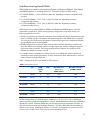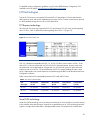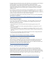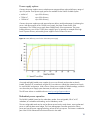
1
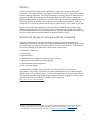
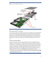
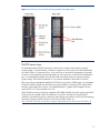
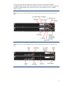
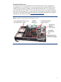
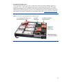
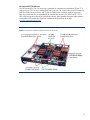
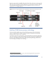
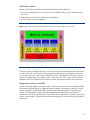
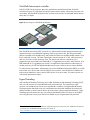
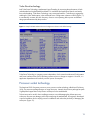
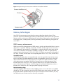
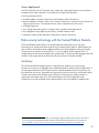
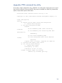
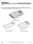
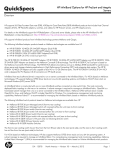
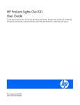
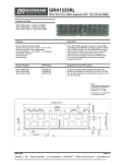
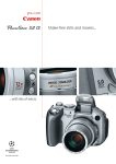
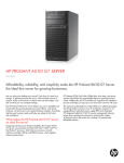
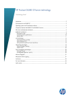
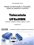
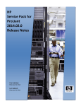
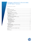
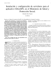
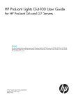
HP ProLiant SL6000 Scalable System technology
technology brief
Abstract.............................................................................................................................................. 3
Mechanical design for extreme scale-out computing................................................................................. 3
HP ProLiant z6000 G6 chassis .......................................................................................................... 4
Rack and cabling options.................................................................................................................. 4
SL6000 server trays ......................................................................................................................... 5
HP ProLiant SL160z G6 server ....................................................................................................... 7
HP ProLiant SL170z G6 server ....................................................................................................... 8
HP ProLiant SL2x170z G6 server ................................................................................................... 9
Intel Xeon 5500 Series processor technology ........................................................................................ 10
Multi-level caches ........................................................................................................................... 11
QuickPath Interconnect controller ..................................................................................................... 12
Hyper-Threading ............................................................................................................................ 12
Turbo Boost technology................................................................................................................... 13
Processor socket technology................................................................................................................ 13
Memory technologies ......................................................................................................................... 14
DDR3 memory enhancements .......................................................................................................... 14
Controlled fan speed .................................................................................................................. 14
Reduced operating voltage .......................................................................................................... 14
Unbuffered and registered DIMMs ................................................................................................... 15
I/O technologies ............................................................................................................................... 16
PCI Express technology................................................................................................................... 16
Serial ATA technology .................................................................................................................... 16
Networking technologies ................................................................................................................ 17
High Performance Computing technologies ....................................................................................... 17
Power and thermal technologies .......................................................................................................... 17
Power supply options...................................................................................................................... 18
Redundant power operation ............................................................................................................ 18
Management and deployment............................................................................................................. 20
Systems management and monitoring............................................................................................... 20
Power and thermal management with the Power Management Controller ............................................. 20
Remote management and control with ProLiant Onboard Administrator ................................................ 22
IPMI 2.0 and DCMI 1.0.................................................................................................................. 22
Server deployment ......................................................................................................................... 23
Data security technology with the Trusted Platform Module ..................................................................... 23
Summary .......................................................................................................................................... 23
Appendix: PPIC command line utility .................................................................................................... 24
For more information.......................................................................................................................... 25
Call to action .................................................................................................................................... 25
Abstract
The HP ProLiant SL6000 Scalable System implements an entirely new mechanical design and
architecture in the industry-standard server market. The SL6000 server family is optimized for extreme
scale-out computing applications such as High Performance Computing, large-scale enterprise server
deployments, and the latest web and cloud computing applications. HP expertise in design and
technology implementation in the SL6000 system led to achieving a record-setting performance in the
SPECpower_ssj2008 ∗ benchmark: In the benchmark report published on November 4, 2009, HP
ProLiant SL2x170z G6 server garnered the SPECpower_ssj2008 result of 2316 overall ssj_ops/watt ∗ .
Based on industry-standard components, the ProLiant SL6000 Scalable System provides extreme
density and high performance at low acquisition costs. SL6000 servers are uniquely serviceable in
racks and are optimized for power and cooling efficiency. Simplified management and monitoring of
each server reduce the cost and effort needed to manage thousands of servers.
Mechanical design for extreme scale-out computing
Computing environments such as High Performance Computing, large-scale enterprise server
deployments, and the latest web and cloud computing applications require unusually high processing
power and density plus maximized operating efficiency. For the ProLiant SL servers, HP developed a
new mechanical design and infrastructure to meet several customer needs:
• Economical purchase price
• Extreme density
• High performance
• Programmable power supplies for maximizing power efficiency
• Highly efficient and inexpensive cooling subsystem
• Integrated remote system management
• Easy, in-rack serviceability
A ProLiant SL6000 Scalable System consists of a 2U ProLiant z6000 G6 chassis and two
self-contained 1U server trays, each with its own industry-standard processors, Double Data Rate-3
(DDR3) memory, I/O, and storage (Figure 1). The rack-mountable chassis includes a highly efficient
and modular power and cooling infrastructure that supports the slide-in pluggable server trays. More
information about the ProLiant SL6000 Scalable System is available at
http://www.hp.com/servers/SL6000.
∗
∗
SPEC® and the benchmark name SPECpower_ssj® are registered trademarks of the Standard Performance
Evaluation Corporation. Benchmark results stated above reflect results published on www.spec.org as
of 11/04/2009. For the latest benchmark results, visit http://www.spec.org/power_ssj2008/.
3
Figure 1. HP ProLiant SL6000 Scalable System
HP ProLiant z6000 G6 chassis
The HP ProLiant Scalable System implements a new chassis/rack architecture in the industry-standard
server market space. The chassis provides shared power and cooling to the system components by
means of one or two high efficiency, HP common slot power supplies and up to four system fans.
Each 2U chassis contains an embedded microcontroller that provides power metering and throttling
capabilities for the entire chassis. The chassis has no midplane and the I/O connectors are at the
front of the chassis to optimize serviceability and to provide unrestricted airflow to the two server
trays.
Rack and cabling options
The z6000 G6 chassis mounts into an industry standard 19-inch rack using standard mounting
hardware or an HP rack using a more cost-effective 10U bulk rail system (only for HP racks). The
standard rail kit or the 10U bulk rail kit can be mixed within the HP rack to optimize the deployment.
In a 42U rack, it is possible to install 21 z6000 G6 chassis containing a total of 42 server trays. To
avoid risk of personal injury or damage to the equipment, HP ProLiant z6000 G6 chassis should be
installed first in the bottom of a rack and added from the bottom to the top until the rack is fully
populated. Network switches provide an aggregation point for all network cables and are typically
installed in the middle of the rack to accommodate shorter cable lengths and to optimize
serviceability. In the rear, all power cables are cleanly installed on the right side of the cabinet (Figure
2). For detailed information about rack and cabling options, refer to the HP ProLiant SL6000 Scalable
System Cabling Guide at this website:
http://bizsupport2.austin.hp.com/bc/docs/support/SupportManual/c01769895/c01769895.pdf.
4
Figure 2. Front and rear views of HP 42U rack fully populated with SL6000 systems
SL6000 server trays
HP developed multiple SL6000 server trays to meet various customer needs: memory capacity,
internal storage, or compute density. The chassis supports two server trays of the same model within
an SL6000 chassis. To optimize air flow, if one server tray is removed for maintenance, fan speeds
increase to ensure adequate cooling of the other tray. If a server tray is removed and a replacement
tray is not immediately available, users should install a tray blank within two minutes to maintain
proper cooling. The z6000 tray blank kit is a core option available for the z6000 G6 chassis.
Each server tray accommodates Intel® Xeon® 5500 Series processors, DDR3 memory, an integrated
Serial ATA (SATA) controller with HP Smart Array software RAID, non hot-plug SATA storage drives
housed in quick-release drive carriers, an integrated dual-port 1 gigabit network adapter, and an
optional PCIe 2.0 x16 slot available on a riser.
While SL6000 server trays include an integrated SATA RAID controller, they also support optional HP
Smart Array SAS controllers and SAS hard drives. For specific information on supported SAS
controllers, SAS hard drive options, and server node storage configuration, refer to the HP technology
document “Configuring SATA and SAS in HP ProLiant SL6000 servers” at
http://h20000.www2.hp.com/bc/docs/support/SupportManual/c01893303/c01893303.pdf.
5
For easy servicing, video and serial ports, USB ports, NIC ports, and optional out-of-band
management LAN ports are located on the front panel of each server tray. Also on the front panel are
two LEDs for health and UID status, and an access port for a low profile PCIe 2.0 x16 adapter
(Figures 3 and 4).
Figure 3. Front view of a ProLiant z6000 G6 chassis fully populated with two HP ProLiant SL170z G6 server
trays
Figure 4. Front view of a ProLiant z6000 G6 chassis fully populated with two HP ProLiant SL160z G6 server
trays
6
HP ProLiant SL160z G6 server
The SL160z G6 server tray is optimized for maximum expansion (Figure 5). The system board
accommodates up to two Intel Xeon 5500 Series processors and up to 18 slots for DDR3 memory
modules (nine per processor). In addition to the optional PCI Express (PCIe) 2.0 x16 slot, there is
room for another optional internal PCIe 2.0 x4 slot. The SL160z G6 server can support large form
factor (LFF), small form factor (SFF), or solid state (SSD) SATA storage drives housed in quick-release
drive carriers. More detailed information about memory configuration and internal drive support is
available in the QuickSpecs at this URL: www.hp.com/servers/SL160z.
Figure 5. Internal view of the HP ProLiant SL160z G6 server tray
7
HP ProLiant SL170z G6 server
The HP ProLiant SL170z G6 server tray is optimized for maximum storage capability (Figure 6). It
supports LFF, SFF, or SSD SATA storage drives housed in quick-release drive carriers. The system
board accommodates up to two Intel Xeon 5500 Series processors and provides up to 16 slots for
DDR3 memory modules (eight per processor). More detailed information about memory configuration
and internal drive support is available in the QuickSpecs at this URL: www.hp.com/servers/SL170z.
Figure 6. Internal view of the HP ProLiant SL170z G6 server tray
8
HP ProLiant SL2x170z G6 server
The HP ProLiant SL2x170z G6 server tray is optimized for compute power and density (Figure 7). It
contains two SL170z G6 server nodes side-by-side in the tray. This means it has up to four sockets for
Intel Xeon 5500 Series processors and 32 slots for DDR3 memory modules (eight per processor).
Each server node has its own embedded SATA controller that accesses one of the two LFF, SFF, or
SSD SATA storage drives housed in quick-release carriers. More detailed information about memory
configuration and internal drive support is available in the QuickSpecs at this URL:
www.hp.com/servers/SL2x170z.
Figure 7. Internal view of the HP ProLiant SL2x170z G6 server tray
9
Because two server nodes are installed side-by-side, the front of the unit has twice as many ports and
LEDs as the SL170z G6 server. Each server node has its own video and serial connectors, USB ports,
NIC ports, health and UID LEDs, optional out-of-band management LAN port, and a slot for an
optional PCIe 2.0 x16 adapter (Figure 8).
Figure 8. Front view of a ProLiant z6000 G6 chassis populated with 2 HP ProLiant SL2x170z G6 server trays
Intel Xeon 5500 Series processor technology
HP ProLiant SL6000 Scalable Systems use Xeon 5500 Series processors that include multi-level
caches, an integrated memory controller, and Intel’s QuickPath Technology to boost bandwidth
between processors, memory, and I/O subsystems.
The Intel Xeon 5500 Series microarchitecture is built on hafnium-based, 45-nanometer, high-k metal
gate, silicon technology to reduce electrical leakage. These small, energy-efficient, high-performance
processors support distributed shared memory, Intel Hyper-Threading technology, and Intel Turbo
Boost Technology with Intelligent Power Technology. 1
1
For additional information about Intel processors, see the HP technology brief titled “The Intel processor
roadmap for industry-standard servers” at
http://h20000.www2.hp.com/bc/docs/support/SupportManual/c00164255/c00164255.pdf.
10
Multi-level caches
Intel Xeon 5500 Series processors have a three-level cache hierarchy (Figure 9):
• An on-core 64-kilobyte Level 1 cache, split into two 32-kilobyte caches: one for data and one for
instructions
• 256-kilobyte, Level 2 cache for each core to reduce latency
• A Level 3 cache of up to 8 megabytes
Figure 9. Block diagram of three-level cache hierarchy for Intel Xeon 5500 Series processors
The Level 3 cache is shared by all cores. It is inclusive, which means that it duplicates the data stored
in each core’s Level 1 and 2 caches. This duplication minimizes latency by eliminating unnecessary
core snoops to the Level 1 and 2 caches. Flags in the Level 3 cache track the cache source of data. If
one core modifies another core’s data in Level 3 cache, the Level 1 and 2 caches of those cores are
updated as well. This eliminates excessive inter-core traffic and ensures multi-level cache coherence.
Integrated memory controller
Instead of sharing a single pool of system memory, each processor accesses its own dedicated DDR3
system memory directly through an integrated memory controller. Three memory channels from each
memory controller to its dedicated DDR3 memory provide a total bandwidth of 32 gigabytes per
second. The three memory channels eliminate the bottleneck associated with earlier processor
architectures in which all system memory access was through a single memory controller over the front
side bus. When needed, a processor can access another processor’s memory through the QuickPath
Interconnect.
11
QuickPath Interconnect controller
Intel Xeon 5500 Series processors attain their performance potential through Intel QuickPath
architecture (Figure 10). High-speed, point-to-point interconnects directly connect the processors with
one another. Intel QuickPath architecture also connects each processor to distributed shared memory
and to the I/O chipset.
Figure 10. Block diagram of QuickPath architecture
Each QuickPath Interconnect (QPI) consists of two unidirectional links that operate simultaneously in
opposite directions using differential signaling. Unlike a typical serial bus, the QPIs transmit data
packets in parallel across multiple lanes, and packets are broken into multiple parallel transfers. Each
link is comprised of twenty 1-bit lanes. Data transfer uses a maximum of 16 bits, while the protocol
and error correction use the remaining 4 bits. The interconnect performs a maximum of 6.4
gigatransfers per second and has a bandwidth of 12.8 gigabytes per second in each direction, for a
total bandwidth of 25.6 gigabytes per second. If an application requests data from the memory of
another processor, the QPI uses high-bandwidth inter-processor communication to retrieve the data.
To reduce power requirements, administrators can use the ROM-Based Setup Utility (RBSU) 2 to set QPI
links to enter a low power state when the QPI links are not active. Once this feature is enabled, the
Intel processor determines when to put the QPI links into a low power state. This reduces power use
with minimal performance impact.
Hyper-Threading
With Intel Hyper-Threading Technology, also called Simultaneous Multi-threading Technology (SMT),
each core can execute two computational threads at the same time. This means that a single
processor can simultaneously execute up to eight threads. In addition, the high-bandwidth memory
subsystem supplies data faster to the two computational processes than traditional front side buses,
and the low-latency cache hierarchy allows more instructions to be processed simultaneously. HyperThreading improves performance per watt, allowing Intel-based ProLiant G6 servers to accomplish
more using the same or less power than servers based on previous-generation Intel processors.
2
RBSU information is provided in the software configuration guide for each server tray. Additional information is
provided in the “HP ROM-Based Setup Utility User Guide” at
http://h20000.www2.hp.com/bc/docs/support/SupportManual/c00191707/c00191707.pdf.
12
Turbo Boost technology
Intel Turbo Boost Technology complements Hyper-Threading by increasing the performance of both
multi-threaded and single-threaded workloads. For workloads and applications that do not benefit
from multi-threading, Turbo Boost Technology can increase performance. Turbo Boost is engaged by
enabling the Turbo Mode option in the Advanced Power Configuration submenu in RBSU (Figure 11).
It automatically increases the clock frequency of active cores operating below power and thermal
design points determined by the processor.
Figure 11. Example of RBSU Advanced Power Configuration submenu with default settings
Turbo Boost Technology is operating system independent, which means that Advanced Configuration
and Power Interface-aware (ACPI) operating systems require no changes to support it. However, it is
application dependent and increases processor power consumption.
Processor socket technology
The latest Intel 5000 Sequence processors use a processor socket technology called Land Grid Array
(LGA). The processor package designs no longer have pins. Instead, the processor package has pads
of gold-plated copper that touch processor socket pins on the motherboard.
Technicians must be careful when installing processors to avoid damaging the delicate processor
socket pins. Because pin damage could require replacing the motherboard, HP engineers developed
a special installation tool to simplify processor installation and reduce the possibility of damaging the
socket pins (Figure 12).
13
Figure 12. Diagram showing how the processor installation tool simplifies installation
Memory technologies
Xeon 5500 Series processors connect directly to memory rather than through a chipset. These
processors support only DDR3 dual inline memory modules (DIMMs). DDR3 is part of the synchronous
dynamic random access memory (SDRAM) group of technologies. Administrators control all processor
functionality options, including memory mirroring and memory channel interleaving, through the G6
server RBSU.
DDR3 memory enhancements
DDR3 has several key enhancements over DDR2 memory, including an 8-bit prefetch buffer for storing
data before it is requested. DDR2 has a 4-bit buffer. For DDR3, the data signal rate can increase to
1333 megatransfers per second (MT/s). Although this is commonly referred to as having a speed of
1333 MHz, the maximum clock speed for the DIMMs is actually 667 MHz. The signal is doublepumped to achieve the data rate of 1333 MT/s. DDR3-1333 DIMMs can operate at clock speeds of
667 MHz, 533 MHz, and 400 MHz with corresponding data rates of 1333, 1066, and 800 MT/s.
Controlled fan speed
HP DDR3 DIMM modules have an integrated thermal sensor that signals the chipset to limit memory
traffic to the DIMM if the DIMM temperature exceeds a programmable critical trip point. Using the
data from these thermal sensors, ProLiant G6 servers can reduce fan speed when memory is idle,
which reduces power consumption. The BIOS in ProLiant G6 servers verifies the presence of the
thermal DIMM sensor during POST. Some third-party DIMMs may not include this DIMM thermal
sensor. If the thermal sensor is absent, a POST message will warn that the DIMM does not have a
thermal sensor, and the fans will run at higher speeds (requiring more power).
Reduced operating voltage
Operating voltage for DDR3 has been reduced: DDR2 operates at 1.8V, while at this writing DDR3
operates at 1.5V and consumes less power than DDR2 DIMMs at the same capacity and speed. Even
though DDR3 DIMMs and DDR2 DIMMs are the same size and have the same number of pins, they
have different key notch locations and are electrically incompatible.
14
Unbuffered and registered DIMMs
DDR3 DIMMs are available as both Unbuffered (UDIMMs) and Registered (RDIMMs). Both UDIMMs
and RDIMMs support error correcting code (ECC). There are three types of DDR3 memory:
• PC3-8500R (RDIMM) —1066 or 800 MT/s data rate, depending on memory configuration and
processor
• PC3-10600E (UDIMM) —1333, 1066, or 800 MT/s data rate, depending on memory
configuration and processor
• PC3-10600R (RDIMM) —1333, 1066, or 800 MT/s data rate, depending on memory
configuration and processor
Administrators can use either RDIMMs or UDIMMs, but RDIMM and UDIMM memory cannot be
mixed within a single server. When choosing memory configurations using DDR3 memory, the
following guidelines are useful:
• UDIMM configurations are limited to a maximum of two UDIMMs per memory channel because the
memory controller must drive the address and command signals to each DRAM chip on a channel.
This results in a 24 GB maximum configuration. Because they require fewer components, UDIMMs
are typically less expensive than RDIMMs.
• RDIMM configurations can provide larger memory capacity because the memory controller only
drives the address and command signals to a single register chip, thereby reducing the electrical
load on the memory controller. Users requiring large memory footprints can install three 8-GB
RDIMMs per channel for a total of 144 GB.
• For smaller memory configurations, installing only one or two DIMMs per memory channel can
potentially increase memory performance. In many instances this allows administrators to clock the
memory channel at a higher data rate.
Table 1 summarizes the choices available for DDR3 memory.
Table 1. DDR3 memory options
Type
DIMM
capacity
(GB)
Rank
Max. data rate in
MT/s (1 or 2
DIMMs/channel
Max. data rate in MT/s
(3 DIMMs/channel)
PC3-8500R
RDIMM
4
quad
1066
800
PC3-8500R
RDIMM
8
dual
1066
800
PC3-10600R
RDIMM
2
dual
1333
800
PC3-10600R
RDIMM
4
dual
1333
800
PC3-10600R
RDIMM
8
dual
1333
800
PC3-10600E
UDIMM
1
single
1333
N/A
PC3-10600E
UDIMM
2
dual
1333
N/A
An RBSU setting allows PC3-10600R memory modules to run at 1333 MT/s with two DIMMs per
channel and without performance degradation. Only HP branded DIMMs have been fully validated to
operate at this speed. Third-party DIMMs may not meet stringent design requirements; therefore, HP
does not recommend configuring third-party DIMMs for 1333 MT/s data rates with two DIMMs per
channel. At this writing, operating the memory at 1333 MT/s is supported only on select ProLiant SL
G6 server trays using the Xeon 5500 Series processors operating at 95W.
15
For detailed memory configuration guidelines, use the Online DDR3 Memory Configuration Tool
available on the HP website: www.hp.com/go/ddr3memory-configurator.
I/O technologies
ProLiant SL G6 server trays incorporate PCIe and SATA I/O technologies. PCIe lets administrators
add expansion cards with various capabilities to the system. SATA is a serial communication protocol
for direct-attached storage devices such as SATA hard drives.
PCI Express technology
All ProLiant SL G6 server trays support the PCIe 2.0 specification. PCIe 2.0 has a per-lane signaling
rate of 5 Gb/s, which is double the per-lane signaling rate of PCIe 1.0 (Figure 13).
Figure 13. PCIe data transfer rates
PCIe 2.0 is backward compatible with PCIe 1.0. A PCIe 2.0 device can be used in a PCIe 1.0 slot
and a PCIe 1.0 device can be used in a PCIe 2.0 slot. For best performance, however, each card
should be used in a slot that supports its logical link size. A ProLiant SL series G6 option allows all
expansion slots to run at PCIe 1.0 speed rather than at PCIe 2.0 speed. Enabling this option saves
power. Administrators can control expansion slot speed through the RBSU under the Advanced Power
Configuration submenu.
Table 2 shows the level of interoperability between PCIe cards and PCIe slots.
Table 2. PCIe device interoperability
PCIe
device type
x4 Connector
x4 Link
x8 Connector
x4 Link
x8 Connector
x8 Link
x16 Connector
x8 Link
x16 Connector
x16 Link
x4 card
x4 operation
x4 operation
x4 operation
x4 operation
x4 operation
x8 card
Not allowed
x4 operation
x8 operation
x8 operation
x8 operation
x16 card
Not allowed
Not allowed
Not allowed
x8 operation
x16 operation
Serial ATA technology
Serial ATA (SATA) technology uses a point-to-point architecture in which each device connects directly
to the controller rather than sharing a common bus as parallel devices do. SATA technology transmits
signals in a single stream rather than in multiple parallel streams. Point-to-point links increase data
16
throughput and improve the ability to locate and fix disk failures. More importantly, serial architecture
solves the problems of c lock skew and signal degradation at higher signaling rates. 3
HP has developed a software RAID solution based on Smart Array firmware. The B110i SATA
Software RAID supports the Array Configuration Utility (ACU), ACU command line interface (CLI),
Simple Network Management Protocol (SNMP) agents, and Web-Based Enterprise Management
(WBEM) providers.
B110i includes an OS-specific driver from HP that uses the embedded controller. It can use RAID 0, 1,
and 1+0 and supports a maximum of two logical drives. The B100i supports up to four 1.5 Gb/s or
3 Gb/s SATA drives. Administrators can move drives to a hardware-based Smart Array controller in a
seamless procedure that maintains the user data and RAID configuration.
For a listing of the complete feature set and support information for the B110i SATA Software RAID,
refer to the B110i user guide at
http://h20000.www2.hp.com/bc/docs/support/SupportManual/c01706551/c01706551.pdf.
Networking technologies
SL G6 servers have an integrated NC362i dual port, 1 Gb network adapter. These servers also
support optional multifunction 1 Gb or 10 Gb Ethernet network adapters that provide several
advantages, depending on the adapter:
• TCP/IP Offload engine (TOE) for Microsoft® Windows® operating systems improves CPU
efficiency.
• Receive-side Scaling (RSS) for Windows dynamically load balances incoming traffic across all
processors in a server.
• iSCSI Acceleration (available on some integrated network adapters) offloads some of the work in
creating iSCSI packets from the processor onto the network controller, freeing up the processor for
other work.
• iSCSI boot for Linux® operating systems enables booting the server from a storage area network
(SAN) and eliminates the need for disk drives in a server.
More information about ProLiant Ethernet network adapters is available at
http://h18004.www1.hp.com/products/servers/networking/index-nic.html.
High Performance Computing technologies
High Performance Computing (HPC) interconnect technologies are available for the ProLiant SL G6
server trays under the HP Cluster Platform product portfolio. HP fully supports these high speed
interconnects when they are part of these configure-to-order clusters. For additional information and
configuration tools, refer to the HP Cluster Platforms website at
http://www.hp.com/techservers/clusters/ucp/index.html.
Power and thermal technologies
To increase power efficiency without degrading server performance, HP has developed highefficiency, right-size power supplies and a common slot (CS) power supply bay that are used in
multiple ProLiant server platforms. Like many other ProLiant G6 servers, the SL6000 Scalable System
supports these common power supplies. By reducing the number of power supply designs for ProLiant
servers, HP effectively reduces the number of spares customers must keep in their data centers.
3
For more information about these features, refer to the technology brief “Serial ATA technology” at
http://h20000.www2.hp.com/bc/docs/support/SupportManual/c00301688/c00301688.pdf.
17
Power supply options
Common slot power supplies come in multiple power ratings and have achieved efficiency ratings of
up to 92 percent. Three power supply options are available for the SL6000 Scalable System:
• 460W AC
up to 92% efficiency
• 750W AC
up to 92% efficiency
• 1200W AC
up to 90% efficiency
Common slot power supplies provide improved power delivery and the advantage of reclaiming lost
power. With the exception of the 1200W power supply, they meet Climate Savers Gold
requirements. The 1200W power supply meets Climate Savers Silver requirements. The power
loading efficiency curve for the 750W power supply (Figure 14) provides an example of the high
levels of power efficiency achieved by power supplies used in ProLiant G6 servers.
Figure 14. Power/Efficiency curve for the 750 W HP power supply
Oversized and lightly loaded power supplies do not run as efficiently as those that are heavily
loaded. Therefore, HP recommends using the HP Power Advisor to identify the optimal power supply
for each SL6000 configuration. With a choice of three power supplies of different wattage, customers
can choose the power supply option that meets, but does not exceed their needs.
The HP Power Advisor is available online at www.hp.com/go/hppoweradvisor.
Redundant power operation
The SL6000 Scalable System has four redundancy modes: User configurable, full AC or DC
redundant, AC redundant with throttling, and no redundancy mode.
The user configurable mode can be used to allocate power levels to each chassis, ensuring that total
power is within the data center budget. The Power Management Controller monitors the chassis
power and uses HP power capping technology to limit the AC input power. This feature is enabled as
part of the LO100i Advanced Pack software license for the nodes.
18
Full AC or DC redundancy requires two power supplies to run the z6000 chassis. If one power supply
fails and the remaining power supply can meet power demands of both server trays, both servers will
continue to run without interruption.
AC redundancy with throttling requires two power supplies to run the z6000 chassis. If one power
supply fails and the remaining power supply cannot support the full load of both server trays, the
servers will throttle using HP power capping technology so that the remaining power supply can
support both trays (Figure 15). Although performance is reduced, the chassis continues to operate
until the failed power supply is replaced. This is the default mode when two power supplies are
installed in the system.
Figure 15. Example of AC redundancy with throttling (default mode)
Running the entire z6000 chassis with one power supply provides no redundancy. The single power
supply will provide power to both trays.
19
In a multimode environment, it is important to ensure that planning is completed prior to selecting the
right power supply for the desired redundancy mode. Use of the HP Power Advisor is highly
recommended for identifying the optimal power supply for each SL6000 configuration. The HP Power
Advisor is available online at www.hp.com/go/hppoweradvisor.
Management and deployment
IT administrators using ProLiant SL6000 Scalable Systems will have different computing requirements.
Consequently, the way they manage, deploy, and control servers can differ. With these requirements
in mind, this section examines the following management topics:
• Systems management and monitoring
• Power and thermal management with the Power Management Controller
• Remote management and control with HP ProLiant Onboard Administrator powered by LO100i
• Intelligent Platform Management Interface (IPMI) 2.0 and Data Center Management Interface
(DCMI) 1.0 standards
• Server deployment
Systems management and monitoring
The SL6000 Scalable System infrastructure operates through its extensive integrated management
capabilities. These capabilities are based on the Power Management Controller and ProLiant
Onboard Administrator powered by LO100i integrated on each server tray. Insight Management
Agents provide alerts that can significantly reduce unplanned downtime. The Insight Management
Agents are based on SNMP, the protocol developed to manage nodes (such as servers, workstations,
routers, switches, and hubs) on an IP network. Network management systems detect problems by
receiving traps or change notices from network devices implementing SNMP.
The ProLiant SL6000 Scalable System uses the same SNMP-based Insight Management Agents
supported by other ProLiant servers. As a result, administrators can use HP Systems Insight Manager
(SIM) 5.3 and greater to manage SL6000 servers. Administrators can also use any other
SNMP-based management tool. The agents can be downloaded from the ProLiant model-specific
“Easy Set-up” CDs or from the Internet at http://www.hp.com/servers/easysetup.
SNMP agents enable the following capabilities:
• Health monitoring for drives, fans, network, power supplies, and temperature
• Alerting, including basic alert notification for Smart Array drive pre-failure only
• Performance monitoring that provides information on processor, memory, free disk space, network
utilization, and I/O
Power and thermal management with the Power Management Controller
Each 2U chassis contains an embedded microcontroller that provides advanced power metering and
capping capabilities for the entire chassis (Figure 16). The Power Management Controller manages
the power capping technology built into the chassis, making extreme density in the rack possible. The
embedded Power Management Controller monitors power consumption throughout the chassis and
throttles processor speed and memory in each node to maintain a preset power budget.
HP provides a simple command-line utility, called PPIC, for reading and configuring the power control
logic of the SL6000 Scalable System. Versions are available for Microsoft Windows Server 2003 and
2008 and for the Linux operating system if the OS IPMI driver is installed. Refer to the appendix for
PPIC command line utility use.
20
Figure 16. HP ProLiant z6000 G6 chassis node, fan, and power control block diagram
Power control logic in the z6000 G6 chassis operates in one of four possible modes as shown in
Table 3.
Table 3. HP ProLiant G6 chassis power control logic modes
Mode
Function
0
No Redundancy. Power Control Disabled. No power throttling will occur.
1
AC Redundancy with throttling. This is the default mode. It provides maximum
performance with power supply redundancy. Power control logic will throttle the
performance of each node if the chassis has only one operational power supply.
In this mode, the servers are expected to survive an unexpected AC power loss to
one of the power supplies.
2
Full AC/DC Redundancy. Power control logic will maintain a power cap value at
the DC rating of a single power supply (460W, 750W, or 1200W), such that if
one power supply experiences a DC or AC failure, the chassis should remain
online and operational. Users should be aware of the minimum power
consumption of the chassis. It must be less than the rating of a single power
supply. Running the PPIC utility with the –c option will provide this information.
3
User Configurable (enabled with LO100i Advanced Pack purchase on the nodes).
The user specifies the total power required to operate the 2U chassis, within the
capabilities of the hardware installed. Before setting this mode, users are strongly
advised to run the PPIC utility with the –c option to calibrate the minimum and
maximum power consumption for the chassis. For accuracy, the –c command
should be run after installing and configuring all hardware and bringing all nodes
online in the 2U chassis. To avoid reduced performance due to throttling, a user
configurable power cap value should not be set below or within 20% of the
minimum power value provided by the –c option.
21
Remote management and control with ProLiant Onboard Administrator
All ProLiant SL servers include ProLiant Onboard Administrator powered by LO100i. ProLiant
Onboard Administrator provides the core embedded management functions in all ProLiant servers.
LO100i works with HP SIM, RBSU, and Option ROM Configuration for Arrays (ORCA) to provide
remote management, deployment, and control functions without additional software. Administrators
can access this functionality locally though the RBSU, or remotely with a web browser through HP
SIM. Additional software functionality can be added with HP LO100i advanced licenses.
HP LO100i Remote Management is hardware and firmware that provides remote server access and
control capabilities through an Ethernet interface. The HP LO100i management interface is active
even when the operating system is not running because it obtains its power from the auxiliary power
plane of the server. It is available as long as the server is connected to an active power source. HP
LO100i Remote Management is compatible with industry standards including IPMI 2.0 for hardware
health, DCMI 1.0, and Secure Sockets Layer (SSL) and Secure Shell (SSH) technology for secure
communications over public and private local area networks. HP LO100i is fully accessible using
popular web browsers including Microsoft Internet Explorer 6.0 (for Microsoft Windows clients),
Firefox 1.5 (for Windows and Linux clients), and Mozilla 1.7.12 (for Windows and Linux clients). HP
LO100i is also accessible using System Management Architecture for Server Hardware Command
Line Protocol (SMASH CLP) for Telnet and SSH sessions.
LO100i Advanced Pack contains all the features of LO100i Standard. Purchasing an optional license
key provides access to Advanced Pack functionality:
• Improvements to HP SIM support through the addition of Insight Management (SNMP) Agents
• Host access to in-band IPMI 2.0 features supported by IPMI-aware operating systems
• DNS Registration—LO100i comes with default host names and will automatically register with the
DNS if DHCP is enabled.
LO100i supports a full-speed shared Ethernet port and a dedicated Ethernet port. LO100i and the
server share the full-speed Ethernet port, using the system network for both. Since the connection is full
speed, it supports Graphic Remote Console and virtual media.
The dedicated Ethernet port is provided for SL series G6 server trays through an optional mezzanine
card and enables a separate management network.
IPMI 2.0 and DCMI 1.0
ProLiant SL G6 server trays and LO100i include IPMI 2.0 and DCMI 1.0 standards so that customers
in heterogeneous environments can manage these servers with either industry standard.
The following are basic compliance mandates:
• Implementation of all mandatory IPMI 2.0 and DCMI 1.0 in-band and out-of-band commands
• Reliable local and remote power on/off/reset through IPMI chassis commands
• Serial over LAN console redirection from a remote server (IPMI 2.0)
• Server identification by device ID, globally unique identifier (GUID), asset tag, and chassis ID
• Accurate system event logging using IPMI
• Reliable in-band keyboard controller style (KCS) interface and out-of-band LAN interface
For more information on HP LO100i remote management, go to www.hp.com/go/LO100.
22
Server deployment
The HP ProLiant Easy Set-up CD provides easy, step-by-step, single- and multi-server server utilities to
streamline server setup. It provides a user experience consistent with SmartStart:
• Boot environment and GUI
• Assisted Installation: Windows 2003 Server and Windows 2008 Server drivers
• Manual installation: Windows 2003 Server, Windows 2008 Server, and Linux drivers (Specific OS
support varies by server. For supported versions, refer to QuickSpecs for each server.)
• HP Insight Diagnostics
• Array Configuration Utility (ACU) to configure array controllers and storage devices
• Array Diagnostics Utility (ADU) to perform array controller hardware tests
• SmartStart Scripting Toolkit and Smart Components for software and drivers
Data security technology with the Trusted Platform Module
The Trusted Platform Module (TPM) is an optional hardware module that can securely store
information such as passwords and encryption keys to authenticate the platform. Administrators can
also use TPM to store platform measurements that help ensure that the platform remains trustworthy.
ProLiant G6 servers support an optional TPM v1.2. A rivet supplied with the optional TPM v1.2
module attaches and secures the module to the system board. To prevent possible damage to the TPM
module or to the system board, the TPM cannot be removed once it has been installed. 4
Summary
The HP ProLiant SL6000 Scalable System is a highly efficient, modular power and cooling
infrastructure with a suite of pluggable server modules designed for extreme scale-out deployments. It
provides right-sized dense server solutions based on industry standards with lower acquisition cost
than traditional rack servers. Designed from the ground up for power efficiency, the ProLiant SL6000
includes server solutions that enhance power efficiency by sharing power supplies and fans to
significantly reduce data center costs. The modular design works with existing data center
infrastructure to provide a tailored solution that provides for easy serviceability in standard racks.
4
For additional information about the TPM, see the HP technology brief titled “Data security in HP ProLiant
servers using the Trusted Platform Module and Microsoft® Windows® BitLocker™ Drive Encryption” at
http://h20000.www2.hp.com/bc/docs/support/SupportManual/c01681891/c01681891.pdf.
23
Appendix: PPIC command line utility
HP provides a simple command line utility, called PPIC, for reading and configuring the power control
logic of the SL product line. Running the PPIC utility from the command line without any command-line
options will provide the options shown below.
HP ProLiant Power Interface Control Utility v.1.09
Copyright (c) 2003, 2009 Hewlett-Packard Development Company, L.P.
Usage: POW [Options]
options:
-d Display and Log Power Status and Configuration
-v verbose data displayed
-s Set Power Configuration Mode
-m<mode>
00= No Redundancy Mode (Power Throttling
Disabled)
01= AC Redundancy with Throttling Mode (Max
Performance w/
Redundancy)
02= Full AC/DC Redundancy Mode
03= User Configurable Mode (LO100 Advanced
License
Required)
-l<power limit> (in Watts - Required for <Mode 03)
-c Calibrate and Display Power Limits
-p Poll and Log Power Readings
-v verbose data logged
-f<frequency> (in secs)
-t<duration of run> (in secs)
-o<name> override output log filename
(default log filename= ppic.log)
24
For more information
For additional information, refer to the resources listed below.
Resource description
Web address
HP ProLiant SL160z G6 Server Software
Configuration Guide
http://bizsupport2.austin.hp.com/bc/docs/support/Suppo
rtManual/c01778682/c01778682.pdf
HP ProLiant SL170z G6 Server Software
Configuration Guide
http://bizsupport2.austin.hp.com/bc/docs/support/Suppo
rtManual/c01814434/c01814434.pdf
HP ProLiant SL2x170z G6 Server Software
Configuration Guide
http://bizsupport2.austin.hp.com/bc/docs/support/Suppo
rtManual/c01769955/c01769955.pdf
HP ProLiant SL6000 Scalable System Cabling
Guide
http://bizsupport2.austin.hp.com/bc/docs/support/Suppo
rtManual/c01769895/c01769895.pdf
HP Power Interface Controller User Guide
http://bizsupport2.austin.hp.com/bc/docs/support/Suppo
rtManual/c01828162/c01828162.pdf
http://h20000.www2.hp.com/bc/docs/support/Support
Manual/c00191707/c00191707.pdf
HP ROM-Based Setup Utility User Guide
“The Intel processor roadmap for industrystandard servers” technology brief
http://h20000.www2.hp.com/bc/docs/support/Support
Manual/c00164255/c00164255.pdf
“Memory technology evolution: an overview of
system memory technologies” technology brief
http://h20000.www2.hp.com/bc/docs/support/Support
Manual/c00256987/c00256987.pdf
“Serial ATA technology” technology brief
http://h20000.www2.hp.com/bc/docs/support/Support
Manual/c00301688/c00301688.pdf
HP Cluster Platforms
http://www.hp.com/techservers/clusters/ucp/index.html
Online DDR3 Memory Configuration Tool
www.hp.com/go/ddr3memory-configurator
HP Power Advisor
www.hp.com/go/hppoweradvisor
Call to action
Send comments about this paper to [email protected].
© 2009 Hewlett-Packard Development Company, L.P. The information contained
herein is subject to change without notice. The only warranties for HP products and
services are set forth in the express warranty statements accompanying such
products and services. Nothing herein should be construed as constituting an
additional warranty. HP shall not be liable for technical or editorial errors or
omissions contained herein.
Microsoft and Windows are U.S. registered trademarks of Microsoft Corporation.
Linux is a U.S. registered trademark of Linus Torvalds.
Intel and Xeon are trademarks of Intel Corporation in the United States and other
countries.
AMD and Opteron are trademarks of Advanced Micro Devices, Inc.
HyperTransport is a licensed trademark of the HyperTransport Technology
Consortium.
TC091104TB, November 2009