1
HP ProLiant Lights Out-100
User Guide
For HP ProLiant ML110 G6, ML150 G6, DL120 G6, DL160 G6, DL160se G6, DL170h G6, DL180 G6,
SL160z G6, SL170z G6, and SL2x170z G6, SL2x170z G6, DL165 G7, and SL165z G7 servers
Part Number 616302-001
March 2010 (First Edition)
© Copyright 2010 Hewlett-Packard Development Company, L.P.
The information contained herein is subject to change without notice. The only warranties for HP products and services are set forth in the express
warranty statements accompanying such products and services. Nothing herein should be construed as constituting an additional warranty. HP
shall not be liable for technical or editorial errors or omissions contained herein.
Confidential computer software. Valid license from HP required for possession, use or copying. Consistent with FAR 12.211 and 12.212,
Commercial Computer Software, Computer Software Documentation, and Technical Data for Commercial Items are licensed to the U.S.
Government under vendor’s standard commercial license.
Microsoft, Windows, and Windows Server are U.S. registered trademarks of Microsoft Corporation. Intel, Pentium, and Itanium are trademarks
or registered trademarks of Intel Corporation or its subsidiaries in the United States and other countries. UNIX is a registered trademark of The
Open Group.
Intended audience
This document is for the person who installs, administers, and troubleshoots servers and storage systems.
HP assumes you are qualified in the servicing of computer equipment and trained in recognizing hazards
in products with hazardous energy levels.
Contents
Operational overview ................................................................................................................... 5
Overview .................................................................................................................................................... 5
New features ............................................................................................................................................... 5
Server management...................................................................................................................................... 5
Server management features ......................................................................................................................... 5
LO100 standard features .................................................................................................................... 6
LO100 optional (licensed) features....................................................................................................... 7
Configuration ............................................................................................................................... 8
Configuring LO100 with the LO100CFG utility .............................................................................................. 8
Configuring network access .......................................................................................................................... 8
Configuring user accounts ............................................................................................................................. 9
Accessing BIOS Setup Utility and using function keys ....................................................................................... 9
Using the serial port ..................................................................................................................................... 9
Enabling serial access ...................................................................................................................... 10
Configuring serial port ...................................................................................................................... 10
Using TCP/IP over Ethernet management port ............................................................................................... 11
Selecting a shared Ethernet management port ..................................................................................... 11
Obtaining a DHCP IP address from the BIOS Setup Utility .................................................................... 12
Using the DNS naming feature .......................................................................................................... 12
Setting up a static IP address from the BIOS Setup Utility ...................................................................... 13
Enabling or disabling Telnet and HTTP services from the BIOS Setup Utility ............................................ 14
TCP and UDP port numbers used by LO100 ........................................................................................ 15
Updating the firmware ................................................................................................................................ 15
Remotely updating the firmware......................................................................................................... 15
Installing firmware through a web browser ......................................................................................... 17
Using LO100 ............................................................................................................................. 19
Using SSL .................................................................................................................................................. 19
Using SSH ................................................................................................................................................. 19
Using the SSH utility ......................................................................................................................... 19
Using the PuTTY utility ....................................................................................................................... 20
Using the OpenSSH utility ................................................................................................................. 20
Using CLP.................................................................................................................................................. 20
CLP syntax ....................................................................................................................................... 21
Base commands ............................................................................................................................... 21
Specific commands .......................................................................................................................... 26
DCMI 1.0 support ...................................................................................................................................... 26
IPMI 2.0 support ........................................................................................................................................ 26
Logging in to LO100 .................................................................................................................................. 27
Logging in through a web browser..................................................................................................... 27
Logging in through the CLP................................................................................................................ 27
Browser main menu options ........................................................................................................................ 28
Controlling server power remotely................................................................................................................ 29
Controlling server power from a browser ............................................................................................ 29
Controlling server power through the CLP ........................................................................................... 30
Monitoring sensors ..................................................................................................................................... 30
Viewing sensor data from a web browser ........................................................................................... 31
Viewing sensor data from the BIOS Setup Utility .................................................................................. 31
Platform event filtering configuration................................................................................................... 32
Platform event trap configuration ....................................................................................................... 33
Using the system event log .......................................................................................................................... 34
Accessing the system event log from a web browser ............................................................................ 34
Accessing the system event log from the CLP ....................................................................................... 35
Accessing the system event log from the BIOS Setup Utility ................................................................... 35
Using Virtual KVM ...................................................................................................................................... 36
Using the remote graphic console ...................................................................................................... 36
System buttons ................................................................................................................................. 39
Using Virtual Media ......................................................................................................................... 40
Accessing the remote console through Telnet ................................................................................................. 42
Redirecting BIOS console text through Telnet ....................................................................................... 43
Redirecting a Linux console ............................................................................................................... 44
Microsoft Windows EMS management ............................................................................................... 45
Hardware Inventory page ........................................................................................................................... 47
User administration .................................................................................................................................... 47
Changing user settings through a web browser ................................................................................... 48
Changing user settings through the CLP .............................................................................................. 48
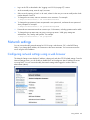
Network settings ........................................................................................................................................ 49
Configuring network settings using a web browser .............................................................................. 49
Configuring network settings using the BIOS Setup Utility ..................................................................... 51
Configuring network settings using the CLP ......................................................................................... 52
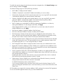
Applying a license key ............................................................................................................................... 52
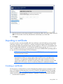
Importing a certificate ................................................................................................................................. 53
Creating a certificate ........................................................................................................................ 53
Installing a certificate or private key through a web browser................................................................. 54
Installing a certificate or private key through the CLP ............................................................................ 55
HP Systems Insight Manager support ............................................................................................................ 56
Resolving character and line feed issues ....................................................................................................... 56
Technical support ........................................................................................................................ 59
Software technical support and update service .............................................................................................. 59
HP contact information ................................................................................................................................ 59
Before you contact HP ................................................................................................................................ 59
Acronyms and abbreviations ........................................................................................................ 61
Index ......................................................................................................................................... 64
Operational overview
Overview
This guide explains the standard and optional operational features of the HP Onboard Administrator
Powered by Lights-Out 100 (LO100) available for the following HP ProLiant server models:
•
ML110 G6 server
•
ML150 G6 server
•
DL120 G6 server
•
DL160 G6 server
•
DL160se G6 server
•
DL170h G6 server
•
DL180 G6 server
•
SL160z G6 server
•
SL170z G6 server
•
SL2x170z G6 server
•
ML110 G6 server
•
DL120 G6 server
New features
This release of LO100 adds support for the following:
•
HP ProLiant DL165 G7 Server
•
HP ProLiant SL165z G7 Server
Server management
LO100 delivers basic remote control of vital server resources, supports IPMI 2.0, DCMI 1.0, and provides
system administrators with access to the server at any time, even before an operating system is installed
on the server.
LO100 provides text mode console redirection, DMTF SMASH compliant command line interface, and
browser access to many of the same system management functions. You can access LO100 through a
dedicated Ethernet port or through the server serial port.
Server management features
With LO100, you can perform the following tasks:
Operational overview 5
•
Access a remote graphic console (Virtual KVM)
•
Access the serial console of the host operating system over the network using standards-based client
utilities
•
Switch between serial console redirection or the LO100 command line interface
•
Communicate securely using SSL and SSH
•
Remotely control the power button of the server (power on and off the server), or perform warm or
cold server reboots
•
Remotely monitor fan speed and system power state (S0 or S5)
•
Access the system event log
•
Access virtual media
•
Configure TCP/IP settings for the LO100 NIC
•
Control user access
•
Discover, identify, and launch LO100 from HP Systems Insight Manager
•
Access LO100 and server controls using a standard browser or new industry-standard SMASH CLP
command line interface
•
Access command line help
•
Manage the server with IPMI 2.0 and DCMI 1.0 compliant applications
•
Access Telnet
Not all of the features displayed and described in the guide are available on all systems. To verify which
features are supported on your system, see "LO100 standard features" and "LO100 optional (licensed)
features" for more information.
LO100 standard features
For HP ProLiant ML110 G6, ML150 G6, DL120 G6, DL160 G6, DL160se G6, DL170h G6, DL180 G6,
SL160z G6, SL170z G6, and SL2x170z G6 servers; and HP ProLiant DL165 and SL165z G7 servers,
LO100 standard features include the following:
•
IPMI 2.0 and DCMI 1.0 elements available through the operating system (where supported)
•
IPMI-over-LAN support
•
Web browser access (HTTP) to power control, system event log, hardware status, and license key
activation of optional features
•
SMASH CLP interface access to remote power control, system event log, hardware status, and
operating system serial console
•
Support for SSL, SSH, and IPMI 2.0 security with factory-default self-signed certificates and keys
Operational overview 6
LO100 optional (licensed) features
LO100 optional features are activated with the purchase of the Lights-Out 100i Advanced Pack package.
The Lights-Out 100i Advanced Pack includes:
•
Virtual media access
•
Virtual KVM
Operational overview 7
Configuration
Configuring LO100 with the LO100CFG utility
The SmartStart Scripting Toolkit is a server deployment product that delivers unattended automated
installation for high volume ProLiant server installations. Available in Win32 and Linux editions, the Toolkit
supports ProLiant DL and ML 300, 500, 700 and ProLiant BL servers in both Windows and Linux
environments and now includes limited ProLiant 100 series support. The toolkit includes a modular set of
utilities and important documentation that describes how to apply these new tools to build an automated
server deployment process.
The toolkit contains an important tool for high volume LO100 configuration and deployment – the
LO100CFG utility. Using this and other configuration tools in the SmartStart Scripting Toolkit will allow
allow rapid, scripted installation of LO100 and other 100 series configurations. See the following Web
page for the SmartStart Scripting Toolkit user guides for Windows and Linux, download links, and
additional information regarding the LO100CFG utility:
http://h18000.www1.hp.com/products/servers/management/toolkit/index.html
Configuring network access
Through your server network connection, you can access the remote management CLP, verify POST
(power-on self test) remotely, access the server through a web browser, and access the BIOS Setup Utility
remotely.
To configure network access:
1.
Connect a standard Ethernet cable from the LO100 NICto a network jack.
2.
Press the F10 key to access BIOS.
3.
Obtain the DHCP IP address.
o
If you are using ML110 G6 or DL120 G6:
i.
Press the right arrow (→) key to scroll to the Advanced tab, and then scroll down to IPMI.
Press the Enter key.
ii. Click LAN Settings, and then click Set IP Address Assignment to DHCP.
o
If you are using or ML150 G6, press the right arrow (→) key to scroll to the Advanced tab, and
then scroll down to IPMI.
o
If you are using DL160 G6, DL160se G6, DL170h G6, DL180 G6, SL160z G6, SL170z G6, or
SL2x170z G6 servers, or DL165 or SL 165 G7 servers, press the right arrow (→) key to scroll to
the Advanced tab, and then use either of the following methods:
i.
Press the down arrow (↓) key to scroll to IPMI Configuration. Press the Enter key.
ii. Click Set LAN Configuration.
Obtain the IP address from BIOS Setup Utility under Advanced/IPMI Configuration/LAN Configuration.
For more information, see "Obtaining a DHCP IP address from the BIOS Setup Utility (on page 12)".
Alternatively, you can perform one of the following methods:
Configuration
8
o
Look at the DHCP clients table.
o
Look at the DNS client records for an entry of LO100<serial server number>. (The default DNS
host name for each LO100 is unique.)
By default, LO100 has DHCP enabled and automatically negotiates an IP address.
4.
With the DHCP IP address, use Telnet to log in to the remote management CLP, or use a web
browser to access the HTML interface.
To set up a static IP address, see "Setting up a static IP address from the BIOS Setup Utility".
Configuring user accounts
LO100 supports four accounts types, with varying levels of permissions to view and control features. For
more information on user accounts, see the "User administration (on page 47)" section. Two accounts are
available by default, one of type administrator and one of type operator.
The administrator account enables the user to execute the full set of CLP commands and change
management processor configuration. The default administrator account user name is admin, and the
default password is admin.
The operator account enables the user to execute common commands and functions but restricts access to
specific functions, such as adding and changing user account information and changing the configuration
of the management processor. HP recommends logging in with the operator account to perform common
functions. The default user name is Operator, and the default password is Operator.
For more information on how to log in to LO100, see the "Logging in to LO100 (on page 27)" section.
Accessing BIOS Setup Utility and using function keys
Throughout the document, the F10 key is listed as the standard method of accessing the BIOS Setup
Utility, saving changes, and exiting the utility. In some cases, the function keys (F keys) might not pass
through the telnet client correctly to the remote system. If this occurs, use the following ESC key
equivalents:
•
F8—ESC+8
•
F10—ESC+0
•
F12—ESC+@
Using the serial port
The server serial port provides basic serial port functionality and serves as an interface to LO100. You
can configure the system serial port for exclusive use with LO100.
CAUTION: After enabling the serial port for use with LO100, legacy serial devices might not
function correctly if attached to the serial port.
You must configure the LO100 serial port hardware parameters to work with your respective serial port
communications software. LO100 serial port configuration is controlled through the BIOS Setup Utility.
Configuration
9
Enabling serial access
1. Power up the server.
2. When POST displays the message, ROM-Based Setup, press the F10 key. If the server has an
administrator password configured, the system prompts you to enter the password. If the server
does not have a password configured, the main screen of the BIOS Setup Utility appears.
3. Press the right arrow (→) key to navigate to the Advanced menu.
4. Choose one of these options:
NOTE: If you change the Serial Port Assignment, the BMC IP Address resets. The BMC IP
address might not be the same after reboot.
o
On ML110 G6 and DL120 G6 servers:
i.
Press the down arrow (↓) key to scroll to Console Redirection.
ii. Set the BIOS Serial Console Port to Enabled.
o
On ML150 G6 servers:
i.
Press the down arrow (↓) key to scroll to IPMI. Press the Enter key.
ii. Set Serial Port Assignment to BMC.
iii. Set Serial Port Switching to Enabled.
iv. Set Serial Port Connection Mode to Direct.
o
On DL160 G6, DL160se G6, DL170h, DL180 G6, SL160z G6, SL170z G6, and SL2x170z G6
servers and DL165 and SL165z G7 servers:
i.
Press the down arrow (↓) key to scroll to IPMI Configuration. Press the Enter key.
ii. Scroll down to Serial Port Configuration.
iii. Set Serial Port Assignment to BMC.
iv. Set Serial Port Connection Mode to Direct.
5.
Press the F10 key to save and exit.
Configuring serial port
1.
Power on the server by pressing the Power On/Off button on the front panel.
2.
When POST displays the message, ROM-Based Setup, press the F10 key. If the server has an
administrator password configured, the system prompts you to enter the password. If the server does
not have a password configured, the main screen of the BIOS Setup Utility appears.
3.
Press the right arrow (→) key to navigate to the Advanced menu.
4.
Press the down arrow (↓) key to scroll to IO Device Configuration, or, if you are using SL160z G6
servers or DL165 or SL165z G7 servers, scroll to Super IO Configurations. Press the Enter key.
5.
Set Embedded Serial Port to 3F8/IRQ4.
6.
From the Remote Access Configuration, configure the BIOS Serial Console as follows:
o
BIOS Serial Console—Enabled
o
EMS Support—Disabled (for ML150 G6)
o
Base Address/IRQ—3F8h, 4
Configuration
10
o
Serial Port Mode—9600 8, n, 1
o
Flow Control—None
o
Redirection after BIOS/POST—Enabled
o
Terminal Type—VT100
For DL 165 G7 and SL 165 G7 servers, from the Remote Access Configuration, configure the BIOS
Serial Console as follows:
7.
o
BIOS Serial Console Port—Enabled
o
BIOS Serial Console Port Baud Rate—[115200 8, n, 1]
o
Redirection after BIOS POST—Always
o
Terminal Type—ANSI
o
VT-UTF8 Combo Key Support—Enabled
8.
Review the serial port settings, and make sure the settings match the serial port communications
software settings used to connect to LO100.
9.
To return to the previous screen, press the Esc key, or to save the changes and exit Setup, press the
F10 key.
Using TCP/IP over Ethernet management port
You can configure LO100 LAN port access using two different Ethernet ports: the dedicated 10/100
LO100 management port or through a side-band connection using the server embedded NIC. The sideband, shared, or UMP options utilize one server Ethernet port for both server network traffic and LO100
network traffic reducing the number of network cables that you must attach to the server.
Selecting a shared Ethernet management port
1.
Power on the server by pressing the Power On/Off button on the front panel.
2.
When POST displays the message, ROM-Based Setup, press the F10 key. If the server has an
administrator password configured, the system prompts you to enter the password. If the server does
not have a password configured, the main screen of the BIOS Setup Utility appears.
3.
Press the right arrow (→) key to navigate to the Advanced menu.
NOTE: On the ML150 G6 system, the Virtual KVM and Virtual Media functions are not
available when used with the Shared NIC function. If you want LO100 Advanced Pack
features on the ML150 G6, use the dedicated NIC mode.
4.
Press the down arrow (↓) key to scroll to IPMI Configuration. Press the Enter key.
5.
Scroll to the LAN Configuration menu by pressing the down arrow (↓) key. Press the Enter key.
6.
Choose one of these options:
a. On ML110 G6 or DL120 G6, press the down arrow (↓) key to IPMI. Press the Enter key, and then
set BMC NIC Allocation to Shared.
b. On ML150 G6, set BMC NIC Mode to Shared.
c.
On DL160 G6, DL160se G6, DL170h G6, DL180 G6, and SL160z G6, SL170z G6, or
SL2x170z G6, set BMC NIC Allocation to Enabled.
d. On DL165 G7, press the down arrow (↓) key to BMC NIC Allocation, then select
Dedicated/Shared. Press the Enter key.
Configuration
11
7.
To return to the previous screen, press the Esc key, or to save the changes and exit Setup, press the
F10 key.
The TCP/IP over Ethernet management port, whether dedicated or shared, is a standard Ethernet
10/100Mb interface that connects to the network using a standard Ethernet cable. Before using the
dedicated management port, you must determine the DHCP IP address or set a static IP address.
Obtaining a DHCP IP address from the BIOS Setup Utility
By default, LO100 has DHCP enabled and automatically negotiates an IP address. To view the DHCP IP
address, run the BIOS Setup Utility or retrieve the DHCP IP address using CLP through the serial port
connection. To view the DHCP IP address using the BIOS Setup Utility:
1.
Power on the server by pressing the Power On/Off button on the front panel.
2.
When POST displays the message, ROM-Based Setup, press the F10 key. If the server has an
administrator password configured, the system prompts you to enter the password. If the server does
not have a password configured, the main screen of the BIOS Setup Utility appears.
3.
Press the right arrow (→) key to navigate to the Advanced menu.
To obtain the DHCP IP address, choose one of these options based on the server model:
On ML110 G6 and DL120 G6 servers:
4.
1.
Press the down arrow (↓) key to navigate to IPMI. Press the Enter key.
2.
Press the down arrow (↓) key to navigate to LAN Settings. Press the Enter key.
Set IP Address Assignment to DHCP.
On ML150 G6 servers:
3.
1.
Press the down arrow (↓) key to navigate to IPMI.
Scroll to BMC LAN Configuration. Press the Enter key.
On DL160 G6, DL160se G6, DL180 G6, and SL160z G6 servers:
2.
1.
Press the down arrow (↓) key to navigate to IPMI Configuration.
2.
Scroll to Set LAN Configuration, and then scroll to BMC LAN Configuration. Press the Enter key.
On DL170h G6, SL170z G6, and SL2x170z G6 servers:
1.
Press the down arrow (↓) key to navigate to IPMI Configuration.
2.
Scroll to LAN Configuration, and then scroll to DHCP IP Source.
3.
Select either of the following:
4.
To set BMC NIC to DHCP, scroll down to DHCP IP Source, and then to enable, press the Enter key.
5.
To save all changes and exit, press the F10 key.
6.
To return to the previous screen, press the Esc key, or to save the changes and exit Setup, press the
F10 key.
7.
To configure or change your network settings, see "Network settings (on page 49)".
Using the DNS naming feature
The DNS naming feature enables you to reference the server name assigned to the server without having
to know the server IP address or obtaining the IP address for a given server. This ability to reference the
server name occurs after the server has registered its name with the DNS, using the default naming
sequence assigned by LO100, LO100 - {Server Serial Number} . (For example, LO100 - CNQ123456.)
Configuration
12
NOTE: This requires DHCP and will not work with static IP addresses. To obtain the serial number, look at
the pull-out tab usually located in the front panel of the server. You can change the server name through
the Network Settings page of the LO100 web interface.
You can also change the server name through the telnet interface.
To do this, type the following in the telnet interface:
cd map1/nic1
set oemhp_hostname=<new_name>
where where <new_name> is the new DNS host name your server will have.
To retrieve a server IP address using the DNS naming feature, use a system connected to the same
network, open a DOS command prompt, and then type nslookup {server name}. (For example, nslookup
{CBQ123456}.)
Depending on your DNS server configuration, it might take up to 45 minutes for the DNS to register a
server name. For more DNS options in LO100, see "Configuring network settings using a web browser
(on page 49)".
Setting up a static IP address from the BIOS Setup Utility
By default, LO100 has DHCP enabled and automatically negotiates an IP address. To disable DHCP and
enable a static IP address:
Press the F10 key during POST to enter the BIOS Setup Utility.
1.
Press the right arrow (→) key to navigate to the Advanced menu.
2.
To set your network BIOS settings, choose one of these options:
o
On ML110 G6 and DL120 G6 servers:
i.
Press the down arrow (↓) key to scroll to IPMI. Press the Enter key.
ii. Press the down arrow (↓) key to scroll to the LAN Settings menu. Press the Enter key.
iii. On IP Address Assignment, select Static.
o
On ML150 G6 servers:
i.
Press the down arrow (↓) key to scroll to IPMI. Press the Enter key.
ii. Press the down arrow (↓) key to scroll to the end, and then select BMC LAN Configuration.
iii. On BMC LAN Configuration, select Static.
iv. Press the down arrow (↓) key to scroll down and enter a valid IP address, subnet mask, and
gateway address (press the Tab key to move between address fields).
o
On DL160 G6, DL160se G6, DL180 G6, and SL160z G6 servers:
i.
Press the down arrow (↓) key to scroll to IPMI. Press the Enter key.
ii. Press the down arrow (↓) key to scroll to the LAN Configuration menu. Press the Enter key.
iii. On DHCP IP Source, select Disabled.
iv. Press the down arrow (↓) key to scroll down and enter a valid IP address, subnet mask, and
gateway address (press the Tab or period (.) key to move between address fields).
o
On DL170h G6, SL170z G6, and SL2x170z G6 servers:
Configuration
13
i.
Press the down arrow (↓) key to scroll to IPMI Configuration. Press the Enter key.
ii. Press the down arrow (↓) key to scroll to the LAN Configuration menu. Press the Enter key.
iii. Press the down arrow (↓) key to scroll to the end, and then select DHCP IP Source.
v. Select either of the following:
— To set BMC NIC to Disabled, press the Enter key.
o
On DL165 G7 and And SL 165 G7 servers:
i.
Press the down arrow (↓) key to scroll to IPMI Configuration. Press the Enter key.
ii. Press the down arrow (↓) key to scroll to the LAN Configuration menu. Press the Enter key.
vi. Press the down arrow (↓) key to scroll to the BMC LAN Configuration menu. Press the Enter
key.
vii. Select DHCP/static, then press the Enter key.
— To save all changes and exit, press the F10 key. To save all changes and exit, press the F10
key.
3.
Press the F10 key to save and exit.
To restore DHCP, see "Configuring network settings using the BIOS Setup Utility."
Enabling or disabling Telnet and HTTP services from the BIOS
Setup Utility
On ML110 G6 and DL120 G6 servers:
1.
Press the down arrow (↓) key to scroll to IPMI. Press the Enter key.
2.
Press the down arrow (↓) key to scroll to the LAN Settings menu. Press the Enter key.
3.
Press the down arrow (↓) key to scroll to the Telnet Services and HTTP Services. Press the Enable or
Disable key as appropriate.
On ML150 G6 servers:
1.
Select Advanced>IPMI.
2.
Set the following:
o
BMC HTTP Service—Enabled or Disabled, as appropriate
o
BMC Telnet Service—Enabled or Disabled, as appropriate
On DL160 G6, DL160se G6, DL180 G6, and SL160z G6 servers and DL165 and SL165z G7 servers:
3.
Select either of the following:
o
If you are enabling or disabling Telnet, select Advanced>IPMI Configuration>LAN
Configuration>BMC Telnet Service.
o
If you are enabling or disabling HTTP, select Advanced>IPMI Configuration>LAN
Configuration>BMC HTTP Services.
4.
To enable or disable, press Enter.
5.
Press the F10 key to save all changes and exit.
On DL170h G6, SL170z G6, and SL2x170z G6 servers:
6.
Press the right arrow key (→) to scroll to the Advanced tab. Press the Enter key.
Configuration
14
7.
Press the down arrow (↓) key to scroll to IPMI Configuration. Press the Enter key.
6.
Press the down arrow (↓) key to scroll to Set LAN Configuration. Press the Enter key.
7.
Scroll to LAN Protocol Control. Press the Enter key.
8.
Press the Enable or Disable key to enable or disable the Telnet or HTTP as appropriate.
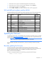
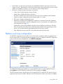
TCP and UDP port numbers used by LO100
The following table lists the TCP and UDP port numbers used by the various LO100 network-accessible
features. You can use this information to configure networking infrastructure or security settings.
Port
number
Protocol
Support
Embedded
by default
22
SSH
Secure Shell connections
Yes
23
Telnet
Command line interface, Remote text console
Yes
80
HTTP
Web-based user interface and LO100
Yes
Virtual KVM
69
TFTP
Firmware upgrade
Yes
162
SNMP trap
HP SIM agent events
Yes
443
HTTPS
Secure access to the web-based user interface
Virtual KVM
Yes
623
IPMI RMCP+
IPMI-over-LAN connections
Yes
664
Secure IPMI RMCP+
IPMI-over-LAN connections
Yes
5901
Storage
Storage
Yes
Updating the firmware
To update the LO100 firmware, use the ROMPaq utility. Downloads for the ROMPaq utility are available
on the HP website (http://www.hp.com/support). For more information about using the ROMPaq utility,
refer to the HP website (http://www.hp.com/servers/manage).
NOTE: LO100 does not support ROMPAQ flashing from virtual media.
After the ROMPaq utility flashes the selected device, cycle power manually to reboot the operating
system.
Remotely updating the firmware
Use the load command to remotely update the LO100 firmware. The firmware file must be an
uncompressed firmware image file created using the DOS ROMPAQ utility found on the Lights-Out 100
Firmware Upgrade Diskette Utility, which is available for download from the HP web site
(http://www.hp.com/servers/lights-out).
To create an uncompressed image file, enter the following command at the DOS prompt:
ROMPAQ /D <infile> <outfile>
Configuration
15
where <infile> is the ROMPAQ firmware image file and <outfile> is the file name for the
uncompressed binary image file. For example:
ROMPAQ /D cpqq0801.D14 ldrImage.bin
ROMPAQ Firmware Upgrade Utility, Version 5.02 (R)
Copyright (c) Hewlett-Packard Corporation, 1994-2006
Input file:
CPQQ0801.D14
Output file:
LDRIMAGE.BIN
The load command is used to retrieve a binary image from a specific source location (specified as a URL)
and place it at the specified target address.
The load command can download and flash a firmware image file using TFTP from the specified location.
To flash the firmware using TFTP settings:
•
On a Windows® operating system:
a. Copy the BMC firmware into a directory on the server.
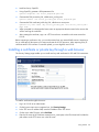
b. Run TFTP by launching the executable file tftpd32.exe.
c. Navigate to TFTP configuration>Settings, and set Timeout to 4 seconds and Max Retransmit to 10.
d. Enter the Base Directory and TFTP Server IP Address. Base Directory is the path where the BMC
firmware is residing. TFTP Server IP Address is the IP address of the TFTP server (for example,
10.141.38.157).
•
On a Linux operating system:
a. Navigate to Applications>Systems Settings>Server Settings>Services and make sure that TFTP and
xinetd are running.
b. Open the /etc/xinetd.d/tftp file and modify the parameter server_args to include -T
4000000. For example, server_args = -c -s /tftpboot -T 4000000.
c. While in this directory, to modify server parameters, type gedit.
d. Reset xinetd to allow it update. Open a terminal and type service xinetd restart. On non-RHEL Linux
platforms, open the Services menu and reset xinetd manually.
e. If a firewall is enabled, disable it or modify the settings to allow the firewall to connect to the TFTP
port. To change the firewall settings, navigate to Applications>System Settings>Security Level,
and enter 69:udp in the parameter of the other port.
f. Place the image file in the tftpboot folder, which is in the TFTP servers root directory.
To update the firmware, log in to LO100 as the administrator through the CLP interface, and issue the
load command to upload and install the firmware from the map1/firmware directory.
1.
Start a CLP session. To access CLP:
a. Navigate to Start>All Programs>Accessories>Command Prompt.
b. At the command prompt, enter telnet <IP address>.
2.
At the CLP prompt, enter cd map1/firmware.
3.
At the CLP prompt, enter load -source <URI> -oemhpfiletype csr
where:
o
<URI> is the //<tftpserver IP>/<filename> to be downloaded.
Configuration
16
o
<tftp server IP> is the URL or IP address of the TFTP server containing the
firmware.
o
<filename> is the file name of the image file (LdrImage.bin in this example).
For example, enter load -source //10.141.38.157/LdrImage.bin -oemhpfiletype csr.
Alternatively, you can also install the firmware through a browser. For more information, see "Installing
firmware through a web browser (on page 17)".
The TFTP application might report an error in the early part of the firmware upload process, during the
firmware image validation process. An error does not necessarily indicate failure of the firmware upload
and does not prevent successful firmware uploads. A successful firmware upload typically takes several
minutes. After the firmware upgrade process is complete, verify that the new version of the firmware is
active.
If the firmware upgrade process fails after sufficient time (at least 5 minutes), reboot the server, and verify
that the previous version of the firmware is still active. Always reboot the server before retrying the
firmware upgrade process.
Do not reset the system or the BMC during download; the server may become corrupt.
After installing the firmware, the IP address of the server might reset to the default value. You must locally
reset the IP address to the desired address.
NOTE: After using the load command LO100 will reset ending your CLP interface session.
You must reconnect to the CLP interface.
NOTE: When you use the CLP load command with TFTPD32, HP recommends using a 4second timeout and 10 retries.
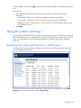
Installing firmware through a web browser
The Firmware Download page enables you to install new firmware images. To install firmware through
the browser:
1. Log in to LO100 as an administrator.
2. On the browser main menu recognition box, click Firmware Download.
3. In the TFTP server IP address field, enter the IP address of the TFTP server.
4. Enter the file name of the firmware image in the File Name field. Include the path relative to the TFTP
server root in the file name.
5. If you are using Linux to install the firmware:
6. Place the image file in the /tftpboot folder, which is in the TFTP servers root directory.
7. Enter the file name of the firmware image in the Firmware File name field. Include the path to the TFTP
server root in the file name.
8. Click Apply.
Configuration
17
After you click Apply, the BMC is reset. You must reconnect to the web browser.
Configuration
18
Using LO100
Using SSL
SSL is a protocol used to transmit private documents through the Internet and uses a private key or
certificate to encrypt data transferred over the SSL connection. The Lights-Out 100 provides security for
remote management in distributed IT environments by using an industry-standard encryption protocol for
data traveling on unsecured networks. SSL is available by default.
LO100 comes preinstalled with a certificate. To install a user-specific certificate, see the one-time
"Importing a certificate (on page 53)" setup procedure.
If you cannot access the login page, you must verify the SSL encryption level of your browser is set to 128
bits. The SSL encryption level within the management processor is set to 128 bits and cannot be changed.
The browser and management processor encryption levels must be the same.
To use the preinstalled certificate, enter https://ipaddress in the address line of the browser, which uses
SSL-encrypted communication. Enter http://ipaddress to use non-SSL encrypted communication.
Using SSH
SSH is a Telnet-like protocol for logging in to and executing commands on a remote machine, which
includes security with authentication, encryption, and data integrity features. The Lights-Out 100 remote
management processor can support simultaneous access from four SSH clients. After SSH is connected
and authenticated, the command line interface is available. LO100 supports two simultaneous SSH
connections. SSH is available by default.
LO100 supports the SSH version 2 and the following client utilities:
•
PuTTY 0.54 or later.
•
OpenSSH
LO100 comes preinstalled with a certificate. To install a user-specific certificate, see the one-time
"Importing a certificate (on page 53)" setup procedure.
Using the SSH utility
When using a SSH utility to connect to a server for the first time, the utility prompts you to accept the
server public key, sometimes referred to as a host key. Accepting this key authorizes the utility to store a
copy of the public key in its own database. The utility recognizes the server when future connections are
attempted by comparing the public key to the one stored in its database.
NOTE: Logging in to an SSH session could take up to 90 seconds. Depending on the client
used, you might not see on-screen activity during this time.
To access the remote management processor using SSH:
Using LO100 19
1. Open an SSH window.
2. When prompted, enter the IP address, login name, and password.
Using the PuTTY utility
PuTTY 0.54 is a terminal emulation product that includes support for telnet and the SSH protocol. PuTTY
0.54 is available for download from the Internet.
•
To start a PuTTY session, double-click the PuTTY icon in the directory in which PuTTY is installed.
•
To start a PuTTY session from the command line:
o
To start a connection to a server called host, enter:
putty.exe [-ssh | -telnet | -rlogin | -raw] [user@]host
o
For telnet sessions, you can also enter the following alternative syntax:
putty.exe telnet://host[:port]/
o
To start an existing saved session called session name, enter:
putty.exe -load "session name"
When you press Enter using PuTTY versions earlier than 0.54, two line feeds might appear on a single
line feed. To avoid this issue and for best results, HP recommends using version 0.54 or later.
Using the OpenSSH utility
OpenSSH is a free version of the SSH protocol available for download on the Internet.
To start an OpenSSH client in Linux, at the command prompt enter:
ssh -l loginname ipaddress/dns name
Using CLP
HP has worked with key industry partners within Distributed Management Task Force, Inc. to define an
industry-standard set of commands. The SMASH suite will standardize manageability interfaces for
servers. The Lights-Out 100 remote management processor implements the command set defined in the
Server Management Command Line Protocol Specification, 1.00 Draft. The CLP replaces the simple CLI
that was released previously and is no longer supported.
The management processor functionality accessible from the SMASH CLP is a low-bandwidth interface
and provides similar functionality to the web interface. The CLP is designed for users who prefer a
nongraphical interface. The CLP is accessible through the following methods:
•
Telnet
•
SSH connection
•
Physical serial port
LO100 CLP supports four simultaneous SSH connections, two SSH connections and two Telnet connection,
or one SSH connection and three Telnet connections. You cannot have more than four simultaneous SSH
connections and up to three (Telnet and SSH) connections at a time.
Using LO100 20
CLP syntax
The general syntax of CLP command is:
<verb> <target> <option> <property>
•
Verbs—The following verbs are supported:
o
cd
o
help
o
load
o
reset
o
set
o
show
o
start
o
stop
o
exit
o
version
•
Target—The default target is the /. The target can be changed by the cd command or by specifying
a target on the command line.
•
Options—The following options are valid:
o
-help/-h
o
-all/-a
•
Properties are the attributes of the target that can be modified.
•
Output—The output syntax is text.
The valid Boolean values for any command are true and false.
General notes
If the commands on the CLP command span more than one line, you cannot navigate between different
lines.
Operating system-specific notes
•
The Microsoft® Windows® 2000 telnet client does not support the Functions keys F1 through F12,
Insert, Home, and End keys. These keys will not work in a Lights-Out 100 command line session.
•
The Backspace key in the Lights-Out 100 CLP implementation is mapped to the value 0x8. Some
client operating systems, Novell Linux Desktop and Red Hat Enterprise Linux 4 Desktop, map the
Backspace key to the value 0x7f, which is used for the Delete key in the Windows® telnet client.
The Backspace key will not work from a client from which it has value of 0x7f. For the Linux clients,
using the Home or the End key enables the Lights-Out 100 CLP service to remap the Backspace key
to use the value 0x7f, making the key functional.
In the Windows® PuTTY client, the Backspace key can be mapped to a value of 0x8 by changing the
setting for Terminal Keyboard to Control-H.
Base commands
•
The help command displays context-sensitive help.
Using LO100 21
Entering help displays all the supported commands. Entering <command> help displays the help message
specific to that command.
o
Help for verbs
Calling help for a verb returns the general syntax and usage associated with issuing that verb. Calling
help for a verb that is not present in the current directory returns an Unsupported Command message. The
following examples are all valid ways to call help for a verb.
— /./-> help show
Usage: show [<target>][<options>][<properties>]
— /./-> show -h
Usage: show [<target>][<options>][<properties>]
— /./-> show -help
Usage: show [<target>][<options>][<properties>]
— /./->
o
Help for targets
Calling help for a target returns any information about the target and its contents. You can call help
for any target that is not contained in the current directory (help map1 can be called from
system1).
— /./-> system1 -h
Invalid command
— /./-> system1 -help
Invalid command
— /./-> help system1
Host System Directory
— /./-> help map1
Management Service Processor Directory
— /./-> cd system1
— /./system1/-> help map1
Management Service Processor Directory
o
Help for properties
Calling help for a property or any other option for which there is no help information returns an
Unsupported Command or Invalid command message. For example:
/./system1/-> show
/./system1
Targets
oemhp_sensors
oemhp_frus
log1
led1
console 1
Properties
Using LO100 22
name=Hewlett-Packard
enabledstate=enabled
Verbs
cd
version
exit
show
reset
start
stop
help
/./system1/-> help name
Unsupported Command
/./system1/-> help enabledstate
Unsupported Command
/./system1/-> help properties
Unsupported Command
/./system1/-> name -h
Invalid command
/./system1/->
•
The exit command terminates the CLP session.
•
The cd command sets the current default target. The context works similar to a directory path. The
root context for the server and the starting point for a CLP system is /. (forward slash period). By
changing the context, you can shorten commands.
For example:
o
The cd command changes the directory.
o
The cd .. command moves up the tree one directory.
o
The cd myfolder command moves to the myfolder folder if myfolder is in the current
directory.
•
The show command displays values of a property or contents of a collection target. For example:
•
/./> show
•
/.
Targets
system1
map1
Using LO100 23
Properties
Verbs
cd
version
exit
show
help
The first line of information returned by the show command is the current context. In the example, /.
is the current context. Following the context is a list of subtargets (Targets) and properties (Properties)
applicable to the current context. The verbs section (Verbs) shows which commands are available in
this context.
The show command can also be specified with an explicit or implicit context and a specific property.
An explicit context is /map1/firmware and is not dependent on the current context. An implicit
context assumes that the context specified is a child of the current context. If the current context is
/map1, then a show firmware command displays the /map1/firmware data. If a property is not
specified, then all properties are shown.
•
The load command moves a binary image from a URL to the map. The load command is used to take
a binary image from a specific source location (specified as a URL) and place it at the specified
target address. In a remote management processor implementation, the firmware downloads a full
image file using TFTP from the specified location and programs flash with the image.
•
In a remote management processor implementation, /map1/firmware is a valid target.
•
The load command supports usage only with the following options.
o
-source <location>—This option must be specified.
o
(h)elp—This option appears on the command line. The command ignores all options and
properties except -output (for terse or verbose output). These options are only valid for this
command when the -help option is used.
o
source <value>—This option specifies the target from which to transfer the binary image. The
value specified must be a valid URL. The format is //tftpserverip/path/filename. This option is
required in the command line when the load command is executed unless -help is used. The file
must be an uncompressed firmware image file that you create using the DOS ROMPAQ utility
found on the Lights-Out 100 Firmware Upgrade Diskette Utility available for download from the
HP website (http://www.hp.com/servers/lights-out).
o
Specify one of the following:
o
"-oemhpfiletype csr" for loading firmware
o
"-oemhpfiletype key" for loading a key
o
"-oemhpfiletype cer" for loading a certificate
Example:
/./map1/firmware/-> load -s //16.110.181.187/404.bin oemhpfiletype csr
Firmware download is in progress.
BMC will be automatically reset once image is programmed and
validated.
Checking Image 197120
Erasing Memory 2227924
Dnlding/Prgming 4194304
Using LO100 24
Time elapsed: 53 seconds.
Download Complete.
•
The reset command causes a target to cycle from enabled to disabled and then to enabled again.
•
The set command assigns a specific value to a property or group of properties. The standard syntax
for the set command is set property=new value.
•
The set command is used to change any changeable property. If the current directory does not
contain the property you want to change, you must specify the target of the property before entering
the property you want to change.
•
The start command causes the system1 target to power on.
•
The stop command causes the system1 target to power off.
•
The version command queries the version of the CLP implementation or other CLP elements. For
example:
•
/./map1/-> version
•
Version 1.00
•
/./map1/-> cd firmware
•
/./map1/firmware/-> version
•
Version 1.00
•
/./map1/firmware/-> show
•
/./map1/firmware
•
Targets
•
Properties
•
fwversion=0.59
•
Verbs
•
cd
•
version
•
exit
•
show
•
reset
•
load
•
help
•
/./map1/firmware/-> show fwversion
•
fwversion=0.59
•
/./map1/firmware/-> fwversion
•
Invalid command
/./map1/firmware/->
Using LO100 25
Specific commands
CLP syntax for specific commands is found in the sections that also describe the functionality through the
Web interface.
DCMI 1.0 support
LO100 supports Data Center Manageability Interface (DCMI). DCMI enables you to simplify platform
management implementations while enhancing robustness. Specifications are derived from Intelligent
Platform Management Interface (IPMI) 2.0, which has been widely adopted by the computing industry for
server management and system-health monitoring. For more information, see the Intel website
(http://developer.intel.com/technology/product/DCMI/index.htm).
IPMI 2.0 support
LO100 supports the industry-standard IPMI 2.0. The IPMI specification defines standardized, abstracted
interfaces that can be used for monitoring and control functions that are built in to the platform hardware.
In addition to supporting the mandatory commands for IPMI 2.0, the following additional IPMI 2.0
features are supported by LO100:
•
•
•
•
•
Additional IPMI 2.0 commands
o
Get Channel Cipher Suites
o
Set/Get Channel Security Keys
o
Suspend/Resume Payload Encryption
Payload types
o
IPMI Message
o
RMCP+ Open Session Request/Response
o
RAKP Message 1 / 2
o
RAKP Message 3 / 4
Authentication algorithms
o
RAKP-none
o
RAKP-HMAC-SHA1
Integrity algorithms
o
None
o
HMAC-SHA1-96
Confidentiality algorithms
o
None
o
AES-CBC-128
Using LO100 26
Logging in to LO100
You can log in to the remote management processor through a web browser ("Logging in through a web
browser" on page 27) or through the CLP ("Logging in through the CLP" on page 27). If you are unsure of
your DHCP IP address, refer to the "Configuring network access" section.
Logging in through a web browser
1.
Browse to the IP address of the remote management processor to access the login screen.
2.
Enter your user name and password. The default user name for the Administrator account is admin,
and the default password is admin. The default user name for the Operator account is Operator,
and the default password is Operator.
Logging in through the CLP
1.
Establish a connection to the remote management processor by launching a telnet session or an SSH
session.
2.
Enter the user name at the login prompt. The default user name for the Administrator account is
admin. The default user name for the Operator account is Operator.
3.
Enter the password at the password prompt. The default password for the Administrator account is
admin. The default password for the Operator account is Operator.
4.
To exit the CLP and enter Console mode, enter the exit command at the command prompt.
Using LO100 27
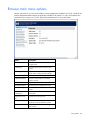
Browser main menu options
Using a web browser, you can access all basic remote management capabilities of LO100. Not all of the
features displayed and described in the guide are available on all systems. To verify which features are
supported on your system, see "LO100 optional (licensed) features" for more information.
Option
Description
Summary
Accesses or returns you to the main menu
navigation bar.
Virtual Power
Accesses system power and UID control
options.
Monitoring Sensors
Lists all sensor information, including type,
name, status, reading, and PEF settings.
System Event Log
Displays the system event log.
Virtual KVM/Media
Accesses virtual media or the remote
graphic console.
Hardware Inventory
Displays system hardware information.
User Administration
Accesses the user configuration screen.
Network Settings
Accesses the network parameter settings
screen.
IPMI PET
Configuration
Accesses the PET destinations and alert
policy table.
Application License
Key
Displays the licensing screen.
Security Settings
Accesses LO100 security, personal
certificate, and key installation options.
Firmware Download
Enables you to flash firmware through the
web browser.
Using LO100 28
NOTE: The Virtual KVM / Media option is an advanced feature available through license
upgrade and not available on all G6 systems unless the license is purchased. This link may
appear as Virtual Media or not at all depending on your system implementation. To verify
which features are supported on your system, see "LO100 optional (licensed) features" for
more information.
Controlling server power remotely
LO100 enables you to remotely operate the power button of a host server using a web browser or the
CLP. LO100 virtual power support enables you to power on, power off, and power cycle the host server.
This virtual power support operates independently of the state of the operating system.
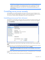
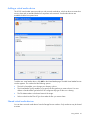
Controlling server power from a browser
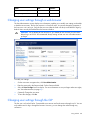
The Virtual Power screen displays current power status, how long the server has been powered on, and
the reason for the last server restart. To display the Virtual Power screen, on the main menu navigation
bar, click Virtual Power.
To modify Chassis Actions, select a Power Control Option in the Chassis Actions section, and then click
Apply.
To identify the server in the rack and illuminate the UID (the LED on the front panel of the server), from the
UID list, select the length of time for the UID to illuminate, and then click Identify.
NOTE: The UID is not available on all LO100 servers. For more information, see your server
user guide.
A restore policy controls how the system responds when power is connected to the server. To set a restore
policy:
1.
Select the Power Restore Policy by choosing one of the following options:
Using LO100 29
2.
o
Always power up—Powers on the server immediately after power is supplied.
o
Restore to powered state prior to power loss—Powers on the system if the system was in the
powered on state before a loss of power.
o
Power pushbutton or command required to power on system—Causes the server to wait for
external action before powering on the system.
Click Set.
The power restore policy becomes becomes active after a successful BIOS post.
Controlling server power through the CLP
1.
Log in to LO100 CLP as described in the "Logging in to LO100 (on page 27)" section.
2.
Change to the system1 target by entering cd system1.
3.
To power on the server, enter start /system1. For example:
i. /./system1/> start /system1
ii. System1 started.
4.
To power off the server, enter stop /system1. For example:
i. /./system1/> stop /system1
ii. System1 stopped.
iii. The -force option can also be used with the stop command. This option forces the
implementation to stop the target, ignoring any policy that might cause the implementation
to normally not execute the command. In remote management processor implementation,
this process is equivalent to a hard power down.
5.
To reset the server, enter reset /system1. For example:
i. /./system1/> reset
ii. System1 reset.
Monitoring sensors
LO100 provides operating system-independent remote monitoring of the current status of major sensors of
a target server including system temperature, fans, and voltage. You can view the data for this feature on
the Monitoring Sensors Page through a web browser or through the BIOS Setup Utility.
Using LO100 30
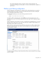
Viewing sensor data from a web browser
The Monitoring Sensors screen displays a snapshot of the temperature, fans, and voltage sensor data,
including sensor type, name, status, and current reading. To access this page from a web browser, on the
main menu navigation bar, click Monitoring Sensor.
To update the display, click the Refresh button. To view or add a PEF action, click PEF. For more
information, see "Platform Event Filtering configuration (on page 32)."
Viewing sensor data from the BIOS Setup Utility
1.
Press the F10 key during POST to enter the BIOS Setup Utility.
2.
Press the right arrow (→) key to navigate to the Advanced menu.
3.
Press the down arrow (↓) key to scroll to IPMI. Press the Enter key.
4.
Choose one of these options based on server model:
o
ML110 G6 and DL120 G6 servers:
iv. Press the down arrow (↓) key to scroll to IPMI. Press the Enter key.
v. Press the down arrow (↓) key to scroll to Realtime Sensor Data. Press the Enter key.
o
On ML150 G6 servers, scroll to Hardware Health Information by pressing the down arrow (↓)
key. Press the Enter key.
o
On DL160 G6, DL160se G6, DL180 G6, and SL160z G6 servers, and DL165 and SL165z G7
servers, scroll to the Hardware Health Information menu by pressing the down arrow (↓) key.
Press the Enter key.
o
On DL170h G6, SL170z G6, and SL2x170z G6 servers, scroll to the Hardware Health
Information menu by pressing the down arrow (↓) key, and then scroll to the Ambient Sensor
Health Information menu. Press the Enter key.
Using LO100 31
The message Loading data. Please wait appears. After this message disappears, the
Temperature and Voltage sensor data appears. This data is real-time data and is updated on a
periodic basis.
Platform event filtering configuration
The PEF Configuration screen enables you to configure LO100 to take selected actions on received or
internally generated event messages. These actions include powering down the system, resetting the
system, and triggering the generation of an alert.
To enable PEF functionality you must issue the following commands in the CLP:
cd map1
oemhp i 20 10 D0 18 00 12 01 03 D2
oemhp i 20 10 D0 18 00 12 02 3F 95
To configure a PEF for a particular sensor, click the PEF button to the far right of that sensor on the
Monitoring Sensors screen. The PEF button adjacent to each sensor opens a PEF Configuration page for
that sensor.
The PEF Configuration screen contains two sections: Current PEF Entries and Add PEF Entry. The Current
PEF Entries section includes Sensor Type, Sensor Name, PEF Action, and PEF Control information. The
Add PEF Entry section enables you set an action.
Initially, there are no entries are in the Current PEF Entries section because no PEFs are defined. When
PEF entries are defined, the PEF Control field is active and enables you to set the individual entries to
enabled, disabled, or deleted.
To configure an action (PEF entry), select the desired Event Offsets, select the desired PEF Action settings,
and then click Add.
Using LO100 32
•
Event Offsets—Are trip points (movements across thresholds) that define what type of sensor event
triggers an action. The information in the Events Offsets section varies with the type of sensor. Not all
options are available for all sensors. You can select any of the available options.
•
PEF Action—Displays the same information for all sensors:
o
Sensor Type—Displays the type of sensor selected.
o
Sensor Name—Displays the name of the sensor.
o
PEF Action—Enables you to select from Power Off, Power Cycle, Hard Reset, and Send Alert
(requires a systems management console supporting IPMI 1.5 or later).
o
PEF Control—Enables or disables the sensor.
o
Alert Policy (list adjacent to the Add button)—Enables you to select an alert policy (if defined).
Alert policies are defined on the PET Configuration screen. For information, see "Platform event
trap configuration (on page 33)."
If alert policies are not defined (default), the Alert Policy list displays No Alert Policy. The Alert
Policy list populates after alert policies are defined and configured. After configuring your alert
policies, you can select from the defined alert policies for this sensor and PEF.
o
Add—Adds the new entry to the PEF Current Entry table at the top of the page.
Platform event trap configuration
The IPMI PEF Configuration screen enables you to set an alarm or specified condition originating on the
server to alert an IPMI 2.0-supported systems management console. To display the IPMI PEF Configuration
screen, on the main menu navigation bar, click IPMI PEF Configuration.
The Global PEF Enable section enables you to set a global PEF action. To create a global PEF action,
select Enabled in the PEF Enable box, select the PEF action, and then click Apply.
The PET Destinations section indicates where LO100 sends the PET (if configured.) This section has up to
eight entries specifying IP and MAC addresses. In the PET Destinations section, enter either an IP address
Using LO100 33
or a MAC address and then click Apply. If both the MAC and an IP address are entered, the IP address is
used.
To set a policy:
1.
2.
Select the Policy Enable state and then enter the Policy Number and Destination Selector
information.
o
Policy Enable—Enables you to selectively enable and disable trap forwarding.
o
Policy Number—Enables you to select a policy that will be used in PEF configuration.
o
Destination Selector—Specifies where to send the PET trap from the destinations defined in the
PET Destinations section.
Click Apply.
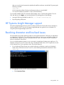
Using the system event log
LO100 captures and stores the IPMI event log for access through a browser, CLP, BIOS Setup Utility, and
RBSU even when the server is not operational. The system event log displays a short description of each
system event. Recorded events include abnormal temperature, fan events, system resets, and system
power loss.
Accessing the system event log from a web browser
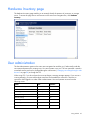
The System Event Log screen displays a brief description of the event, including event type, date, time,
source, description, and direction.
To access the System Event Log from a web browser, on the main menu navigation bar, click System
Event Log. To clear the system event log, click Clear Event Log.
Using LO100 34
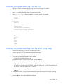
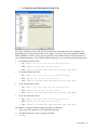
Accessing the system event log from the CLP
1.
Log in to the CLP as described in the "Logging in to LO100 (on page 27)" section.
2.
Enter cd /./system1/log1
3.
Enter show to display the total number of system event records.
4.
Enter show record<n> to display the details of a specific record. For example:
/./map1/log1/-> show record1
record
Targets
Properties
number=1
date=05/07/2008
time=16:42:52
sensordescription=Identify
eventdescription=State Asserted
eventdirection=Assertion
Verbs
cd
version
exit
show
reset
oemhp
help
Accessing the system event log from the BIOS Setup Utility
1.
Press the F10 key during POST to enter the BIOS Setup Utility.
2.
Press the right arrow (→) key to navigate to the Advanced menu.
3.
Press the down arrow (↓) key to scroll to IPMI. Press the Enter key.
4.
Choose one of these options based on server model:
o
On ML110 G6 and DL120 G6 servers:
i. Press the down arrow (↓) key to scroll to IPMI. Press the Enter key.
ii. Press the down arrow (↓) key to scroll to System Event Log. Press the Enter key.
o
On ML150 G6 servers, scroll to the bottom of the IPMI page.
o
On DL160 G6, DL160se G6, DL170h G6, DL180 G6, SL160z G6, SL170z G6, and SL2x170z
G6 servers, and DL165 and SL165z G7 servers:
iii. Scroll to the System Event Log Configuration menu by pressing the down arrow (↓) key. Press the
Enter key.
iv. Press the down arrow (↓) key to scroll to either Clear System Event Log or View System Event Log,
as appropriate.
5.
Press the Enter key to view the highlighted setup item.
Using LO100 35
6.
Press the Esc key to return to the previous screen, or press the F10 key to save the changes and exit
Setup.
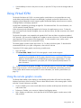
Using Virtual KVM
The Virtual KVM feature of LO100 is a remote graphic console that turns a supported browser into a
virtual desktop and provides full control over the display, keyboard, and mouse of the host server. The
operating system-independent console supports graphic modes that display remote host server activities,
including shutdown and startup operations.
Virtual KVM is available by purchasing the Lights-Out 100i Advanced Pack. For more information, see
"LO100 optional (licensed) features."
When connecting to the Virtual KVM applet for the first time, the applet reports an error. To clear the
error and connect to the Virtual KVM applet, close your browser session, and then reconnect to the Virtual
KVM applet.
The Virtual KVM applet is not compatible with standard VNC clients and does not implement standard
VNC protocols. You must use the supplied Java™ applet to connect to the server. The Virtual KVM applet
cannot pass the F10 key sequence to the target system. To work around this issue, use the virtual
keyboard on the remote server to transmit the F10 key.
The remote graphic console requires JVM version 1.4.2 or later in the client system. To download the
recommended JVM for your system configuration, refer to the HP web site
To start the LO100 remote graphic console using a web browser:
1.
Log in to LO100.
2.
Click Virtual KVM / Media. The LO100 remote graphic console window appears.
NOTE: The Virtual KVM / Media option is an advanced feature available through license
upgrade and not available on all G6 systems unless the license is purchased. This link may
appear as Virtual Media or not at all depending on your system implementation. To verify
which features are supported on your system, see "LO100 optional (licensed) features" for
more information.
3.
To take full control of the system, click OK, or to access the system in a view-only mode, click Cancel.
Before using the mouse in LO100 remote graphic console, HP recommends synchronizing your local
mouse pointer and the remote mouse pointer. For more information, see "Mouse synchronization (on
page 38)."
Using the remote graphic console
The Remote KVM/Media Viewer displays a virtual desktop and provides full control over the display,
keyboard, and mouse of the host server. There are three different menus in the remote graphic console
menu bar: Control, Preferences, and Help.
•
Control—Enables you to access virtual media devices and the virtual keyboard, refresh the screen,
and exit the client.
•
Preferences—Enables you to set mouse, keyboard, and logging options.
•
Help—Displays an About box, which specifies the LO100 remote graphic console version, build
date, and time.
Using LO100 36
The Control menu of the remote graphic console has several different options.
•
Virtual Media—Displays the Virtual Media Devices page. The Virtual Media Devices page displays
all accessible media drives of the storage server. Supported devices are CD-ROM, DVD-ROM, floppy
disk, and mass storage devices. For more information, see "Using Virtual Media (on page 40)."
•
Virtual Keyboard—Opens a virtual keyboard enabling you to change the language of the virtual
keyboard. To change keyboard settings, see "Remote graphic console settings (on page 37)."
The Lock button on the Virtual Keyboard is added to each language. If you click the Lock button,
special keys that you press, such as Shift, Alt, Ctrl, context and Windows® remain in a pressed
status. To release the special keys, click the Lock button and then click the pressed special keys.
NOTE: When entering any ESC key sequences, extra characters might be buffered, causing
the remote side to receive function key presses incorrectly. To avoid this issue and perform
function key or alternate key sequences, press and hold the ESC key, release it, and then
press the other key sequence.
•
Turn local monitor on—Powers on the local monitor.
•
Turn local monitor off—Powers down the local monitor.
When the Turn local monitor off setting is enabled, the local monitor (if connected) appears black
(blank/off) when Virtual KVM is invoked. This is a security feature. The local monitor returns to
normal operation after closing Virtual KVM.
The Virtual KVM applet is not compatible with standard VNC clients and does not implement
standard VNC protocols. You must use the supplied Java™ applet to connect to the server. The
Virtual KVM applet cannot pass the F10 key sequence to the target system. To work around this
issue, use the virtual keyboard on the remote server to transmit the F10 key.
•
Refresh Screen—Updates the information on the screen.
•
Take Full Control—Enables you to take control of the remote console if you are currently in view-only
mode. Only one remote console user can control the remote console at a time.
•
Disconnect Session—Disconnects the selected user session.
•
Relinquish Full Control—Releases control of the session and remains in a view-only status.
•
Exit—Closes the remote session.
NOTE: The Keyboard, Refresh Screen, Take Full Control, Disconnect Session, and Relinquish
Full Control menu options are an advanced feature available with full Virtual KVM access
only.
Remote graphic console settings
To change the mouse, keyboard, and logging settings, select Preferences.
•
The Mouse tab enables you to set the Mouse mode. To display the Mouse Mode list, select Mouse,
which has the following options:
o
Hide Mode (Relative) causes the LO100 remote graphic console to change to Relative mode.
Relative mouse mode hides the local mouse cursor. Use Hide Mode Relative if you are running a
DOS-based program and the mouse is not tracking correctly.
Using LO100 37
When using Hide Mode, the local mouse is inaccessible. To access the local mouse (normal
mode), press Ctrl+Alt+0.
•
o
Absolute Mode causes the LO100 remote graphic console to send raw x and y coordinates to
the server.
o
Relative Mode sends the LO100 remote graphic console relative mouse position coordinates (+/previous mouse pointer position) to the server. This mode is the default for Linux and Windows®.
The Keyboard tab enables you to set the language of the virtual keyboard and the connection type.
English is the default language. You can change the language of the virtual keyboard by selecting
one of the 12 languages.
The remote side server and local side server (the LO100 remote graphic console) must use the same
language for the virtual keyboard to function properly.
LO100 supports the following connection types:
•
o
VNC (port 5900) supports Virtual KVM and LO100 Virtual Media. Port 5900 is the default
setting.
o
Unsecured keyboard (port 5902) supports the keyboard. Port 5902 supports video, mouse, and
LO100 Virtual Media.
o
Secure keyboard (port 5904) encrypts all keyboard data sent through this port. Port 5904 is a
unsecured port that supports video, mouse, and LO100 Virtual Media.
The Logging tab enables you to view log messages in a Java™ console. The Logging tab also
provides a timeout variable to inform you of how long you can stay in KVM.
Global Logging is disabled by default. If you enable this option, you can view log messages in a
Java™ console.
Do not run the console longer than 2 hours. The console uses all available memory and might cause
the LO100 remote graphic console and the user web browser to crash. Periodically clear the event
log to prevent a slow connection or possible crash.
To record all log messages to the console from the Logging list, select Console. To check log
messages in the Java™ console window, from the list on the Tools menu of Internet Explorer menu
bar, select Sun Java Console.
To record all log messages to a file, select Log File from the Logging list, enabling the Console Log
File textbox. To select a file in which log messages will be stored, click the Browse button, or enter
the fully qualified file name of the selected file in the textbox. To send log messages to both a file of
your choice and to the Java™ console, select Console and Log File.
Mouse synchronization
To synchronize the local mouse pointer and the server mouse pointer, bring the local mouse to the top left
corner to attract the server mouse pointer to the top left corner. Both pointers become synchronized when
they overlap as one pointer.
For mouse synchronization to work correctly, you must change the Enhance Mouse pointer and Hardware
Acceleration options on the remote machine (server side) using the LO100 remote graphic console.
For Windows® operating systems, perform the following steps:
To change the Enhance Mouse pointer option:
1.
Select Start>Control Panel.
2.
Double-click Mouse. The Mouse Properties window appears.
Using LO100 38
3.
Select Pointer Options.
4.
In the Pointer Options window:
a. Set the Pointer speed bar in the middle.
b. Be sure the Enhance pointer precision option is not selected.
To change the Hardware Acceleration option:
1.
Right-click the desktop screen
2.
Select Properties. The Display Properties window appears.
3.
Click Settings>Advanced. The video card and monitor properties window appears.
4.
Click Troubleshoot.
5.
Set hardware acceleration to None to disable cursor and bitmap accelerations (one scale or option
below Full).
6.
Click Apply.
7.
Click OK to exit the Display Properties window.
For Linux operating systems, perform the following steps:
•
For SLES 9:
a. Determine which mouse device is the remote console mouse using the xsetpointer -l
command to list all mouse devices.
b. Determine which mouse to modify by cross-referencing the output of xsetpointer with the X
configuration (either /etc/X11/XF86Config or /etc/X11/xorg.conf.)
c.
Select the remote console mouse as the mouse to modify. For example:
xsetpointer Mouse[2]
d. Set the acceleration parameters. For example:
xset m 1 1
•
For Red Hat Enterprise Linux, set the acceleration parameters using:
xset m 1 1
System buttons
On the virtual keyboard, there are eight different system buttons: LCtrl, LWin, LAlt, RAlt, RWin, RCtrl,
Context, and [Lock]. These buttons can be used as virtual keys and are similar to the keys the physical
keyboard of your local machine.
For example, when you press the Ctrl+Alt+Del keys on the physical keyboard, the Task Manager of your
local machine appears in addition to the task manager on the server, or the key combination unlocks the
server for login. To display the Task Manager of the remote server by pressing similar virtual keys, on the
LO 100 remote graphic console window, click LCtrl click LAlt, and then press the Del key on your physical
keyboard. Using this key combination displays the LO100 remote graphic console Task Manager. You
can use any combination of virtual and physical Alt, Ctrl, and Del keys.
•
Lock and special buttons, when pressed, remain in a pressed state until released. To release special
buttons, click [Lock], and press the system buttons.
•
Selecting or pairing LCtrl and RCtrl, LAlt and RAlt, LWin and RWin function as they would on an
English language keyboard. However, they might function differently on keyboards of other
languages.
Using LO100 39
•
Clicking Context is equivalent to right-clicking the LO100 remote graphic console window.
Using Virtual Media
LO100 Virtual Media enables you to add, browse, remove, and share media devices and refresh the
displayed virtual media devices list. LO100 Virtual Media is available by purchasing the Lights-Out 100i
Advanced Pack. For more information, see "LO100 optional (licensed) features."
To access LO100 Virtual Media:
1.
Click Virtual KVM / Media. The Virtual KVM screen appears.
2.
On the Virtual KVM menu, select Virtual Media from the Control menu. The Virtual Media window
appears and has the following options:
3.
Clicking Add adds a new virtual media device to the storage devices list. See "Adding a virtual
media device (on page 41)" for more information.
4.
Clicking Connect shares the selected device. Only one device can be shared at one time.
5.
Selecting a device and clicking Remove removes devices from the virtual media devices list.
6.
Clicking Refresh rescans and displays the current devices on your machine.
A CD-ROM, DVD-ROM, or ISO image mounted through the Virtual KVM or Virtual Media applet functions
and appears (in boot order) the same as a locally mounted media device.
Using LO100 40
Adding a virtual media device
The LO100 virtual media option provides you with a virtual media drive, which can direct a remote host
server to boot and use standard media from anywhere on the network. Virtual media devices are
available while the host system boots.
To add a new virtual media device, click Add on the Virtual Media page. The Add Virtual Media Devices
window appears. This window has the following options:
•
The Look In list enables you to change your directory or drive.
•
The Virtual Media Type list enables you to specify the file type that you want to share. You must
declare a Virtual Media Type before LO100 recognizes they type of device it is sharing.
•
The File Name textbox is the shared name of the image.
•
Select a value from the Files of Type list to select the files you want to share.
Shared virtual media devices
You can share a virtual media device from the Storage Devices window. Only one device may be shared
at a time.
Using LO100 41
To share a virtual media device, do the following:
1.
On the Virtual KVM menu, select Virtual Media from the Control menu. The Virtual Media window
appears.
2.
If the device you want to add is not in the list, click Refresh.
3.
To add a device, see "Adding a virtual media device (on page 41)".
4.
Select the device, and then click Connect. A message box appears, indicating either the device has
been successfully connected or a problem has occurred.
5.
Click OK to close the Virtual Media window.
6.
To remove a shared virtual media device, do the following:
7.
Before removing a shared device, verify the device is safe to remove. If necessary, perform any
required steps necessary to ensure the safe removal of removable media devices on the server.
8.
On the Virtual KVM menu, select Virtual Media from the Control menu. The Virtual Media window
appears.
9.
Select the device you want to remove and click Remove. A dialog box appears, indicating that the
device has been successfully disconnected.
10. Click OK to close the Virtual Media window.
Accessing the remote console through Telnet
You can access the remote console through either the BIOS console text-redirection functionality or a
Windows Server® 2003 text-based console. Only one Remote Console window can be open at a time.
To start a remote console session, press the Esc+Q keys. To end a remote console session and return to the
CLP press the Esc+( keys.
NOTE: When entering any ESC key sequences, extra characters might be buffered, causing
the remote side to receive function key presses incorrectly. To avoid this issue and perform
function key or alternate key sequences, press and hold the ESC key, release it, and then
press the other key sequence.
To change the timeout settings for telnet and for the remote console use Linux raw IPMI commands or an
oemhp command through telnet. The following examples disable timeout:
•
Linux IPMI tool Raw command example:
ipmitool raw 0x0c 0x01 0x02 0xf6 0x00 0x00
•
Disabling the security timeout using telnet example:
oemhp i 20 30 b0 18 00 01 02 f6 00 00 ef
The expected response is:
18 34 B4 20 00 01 00 DF
.4......
NOTE: These commands only work in firmware versions 3.05 or later.
Using LO100 42
Redirecting BIOS console text through Telnet
LO100 BIOS console text redirection enables you to view the entire boot process remotely and make
changes in the BIOS Setup Utility from a remote computer. This utility helps you troubleshoot and manage
servers remotely.
To configure the BIOS Setup Utility on the target system:
1.
Press the F10 key during POST to enter the BIOS Setup Utility.
2.
Press the right arrow (→) key to navigate to the Advanced menu.
3.
Choose one of these options based on your server model:
On ML110 G6 and DL120 G6 servers:
o
i.
Press the down arrow (↓) key to scroll down to the Console Redirection option, and press the
Enter key.
ii.
Set BIOS Server console to Enabled.
— Baud Rate—9600 (this is the only setting that can be changed)
On ML150 G6 servers:
o
i.
Press the down arrow (↓) key to scroll down to the Console Redirection option, and press the
Enter key.
ii.
Verify the following settings:
— Console Redirection—Enabled
— Serial Port Mode—9600 8,n,1
— Terminal Type—VT100+
— Flow Control—None
— Redirection after BIOS POST—On
On DL160 G6, DL160se G6, DL170h G6, DL180 G6, SL160z G6, SL170z G6, and SL2x170z
G6 servers and DL165 and SL165z G7 servers:
o
iii.
Press the down arrow (↓) key to scroll down to the Remote Access Configuration option, and
then press the Enter key.
iv.
Verify the following settings:
— Remote Access—Enabled
— EMS support(SPCR)—Enabled
— Base Address—IRQ4/3F8
— Serial Port Mode—9600 8,n,1
— Flow Control—None
— Terminal Type—VT100
— Redirection after BIOS POST—Enabled
4.
Press the Esc key to return to the previous screen.
5.
Scroll to the I/O Device Configuration option, and press the Enter key.
6.
Verify that Serial Port is set to Enabled.
7.
Follow the instructions in the "Network settings (on page 49)" section to set or obtain a valid IP
address.
Using LO100 43
8.
Press the F10 key to save and exit.
After completing the console redirection process, you can view the boot process remotely from a client PC
through an established Telnet session to the IP address of LO100. See your operating system
documentation for instructions on establishing telnet sessions.
To redirect the console to the Telnet session and view the boot process, press the Esc+Q keys in the Telnet
session during server boot. If you reset the server using the Telnet connection, and press the Esc+Q keys,
the boot process might not appear immediately. The boot process appears after the server resets. To exit
the console redirection and return to CLP, end this session by pressing the Esc+( keys.
NOTE: If you encounter problems logging in to the remote console, be aware that some telnet
programs might require you to enable their send line feed at end of line option. If
the remote console does not respond to the Enter key, try setting this option in your telnet
program.
NOTE: You must follow the instructions in the "Network settings (on page 49)" section to
configure the network access properly.
Redirecting a Linux console
In the remote console and servers with the Linux operating system, you can enable a remote login on
ttyS0 by making the following changes to the BIOS Setup Utility and boot documents.
NOTE: The actual steps will vary depending on your version of Linux.
1.
Using the BIOS Setup Utility, verify your system configuration by choosing one of these options
based on your server model:
o
On ML110 G6 and DL120 G6 servers, verify the following settings:
Console Redirection
— BIOS Serial console—Enabled
— Baud Rate—9600
I/O Device Configuration
— Embedded Serial Port Mode—BMC
— Embedded Serial Port—Enabled
o
On ML150 G6 servers, verify the following settings:
Console Redirection
— BIOS Serial console—Enabled
— EMC Support (SPCR)—Enabled
— Serial Port Mode—9600 8,n,1
— Console Type—VT100
— Continue C.R. after POST—On
I/O Device Configuration
— Serial Port A—Enabled
Using LO100 44
— Base I/O address—3F8
— Interrupt—IRQ 4
o
On DL160 G6, DL160se G6, DL170h G6, DL180 G6, SL160z G6, SL170z G6, and SL2x170z
G6 servers, and SL165z G7 servers, verify the following settings:
Remote Access Configuration
— Remote Access—Enabled
— EMS support(SPCR)—Enabled
— Terminal Type—VT100
— Flow Control—None
— Redirection after BIOS POST—Always
SuperIO Configuration
— Serial Port Address—3F8
— Serial Port IRQ—IRQ 4
2.
In the /boot/grub/menu.lst file, append the following to the kernel startup line:
console=ttyS0 115200
Comment out the line GRAPHICAL DISPLAY LINE
# splashimage=(hd0,0)/grub/splash.xpm.gz
3.
Add an entry to allow serial console login in /etc/inittab. For example:
S0:12345:respawn:/sbin/agetty -L 115200 ttyS0 vt102
4.
In /etc/securetty enable root access to ttyS0 by adding ttyS0.
5.
In /etc/sysconfig/kudzu, set kudzu to not perform serial port probing during boot. For example:
SAFE=yes
6.
After modifying and saving the previous files, reboot the server. You can now log in to the operating
system through remote console.
After POST, in the remote console, the server prompts you with a login. Enter a valid login and use the
server as you normally would. Use the ESC+Q keys to start remote console through the telnet and the
ESC+( keys to exit the remote console in telnet.
Microsoft Windows EMS management
Windows Server® 2003 provides text-based console access. You can connect a notebook to LO100 to
perform basic management tasks on the target system. The Windows® EMS Console, if enabled, displays
the processes that are running and enables administrators to halt processes when video, device drivers, or
other operating system features have prevented normal operation and normal corrective actions.
To enable Windows® EMS management on the target system:
1.
Press the F10 key during POST to enter the BIOS Setup Utility.
2.
Navigate to the Advanced>Console Redirection menu.
3.
Choose one of these options based on your server model:
o
On ML110 G6 and DL120 G6 servers:
i.
Press the down arrow (↓) key to scroll down to the Console Redirection option, and then press
the Enter key.
Using LO100 45
Verify the following settings:
— Baud Serial Console Port—Enabled
— Baud Rate—9600
o
On ML150 G6 servers:
i.
Press the down arrow (↓) key to scroll down to the Remote Access Configuration option, and
then press the Enter key.
ii. Verify the following settings:
— Remote Access—Enabled
— EMS support (SPCR)—Enabled
— Serial Port Mode—9600 8,n,1
— Flow Control—None
— Console Type—VT100
— Continue C.R. after POST—Always
o
On DL160 G6, DL160se G6, DL170h G6, DL180 G6, SL160z G6, SL170z G6, SL2x170z G6
servers, and DL165 and SL165z G7 servers:
i.
Press the down arrow (↓) key to scroll down to the Remote Access Configuration option, and
then press the Enter key.
ii. Verify the following settings:
— Remote Access—Enabled
— EMS support(SPCR)—Enabled
— Serial Port Mode—9600 8,n,1
— Terminal Type—VT100
— Flow Control—None
— Redirection after BIOS POST—Always
4.
Press the Esc key to return to the previous screen, or press the F10 key to save the changes and exit
setup.
After enabling Windows® EMS management, you can view the Windows® EMS management console
remotely from a client PC through an established Telnet session to the IP address of the target server by
pressing the Esc+Q keys. You can end an EMS session by pressing the Esc+( keys. See your operating
system documentation for instructions on establishing Telnet sessions.
NOTE: If you encounter problems logging in to the remote console, be aware that some telnet
programs might require you to enable their send line feed at end of line option. If
the remote console does not respond to the Enter key, try setting this option in your telnet
program.
Using LO100 46
Hardware Inventory page
The Hardware Inventory page enables you to remotely identify the presence of processors on a target
server. To access this page from a web browser on the main menu navigation bar, click Hardware
Inventory.
User administration
The User Administration option on the main menu navigation bar enables you (if authorized) to edit the
user name and password for existing users. You cannot create a new user. The user password is stored in
nonvolatile memory and can be changed through a web browser ("Changing user settings through a web
browser" on page 48) or through the CLP.
When using CLP, if you do not have the correct privileges a warning message appears. If you receive a
warning message, you must end the telnet connection and re-establish a connection. There are no
restrictions when logged in as either OEM or administrator. User and operator accounts have the
following access.
Option
User
Operator
Hardware Inventory
Yes
Yes
Virtual Power
No
Yes
Monitoring Sensors
View only
Yes
System Event Log
Yes
Yes
Network Settings
No
No
PET Configuration
No
No
User Configuration
No
No
Virtual KVM
No
No
Using LO100 47
Option
User
Operator
Application License Key
No
No
Security Settings
No
No
Changing user settings through a web browser
The User Administration screen displays user information, enables you to modify user settings, and enable
or disable user accounts. The first user account is a fixed null value. You cannot change the properties of
the first user or use it to log in. Only the first two users (after the fixed null value) are enabled for login by
default. Users can only be enabled from the browser interface.
WARNING: Do not disable all user accounts. If you disable all user accounts you will not be
able to log in to LO100. HP recommends always leaving at least one user with administrative
privileges.
To modify user settings:
1.
On the main menu navigation bar, click User Administration.
2.
Enter the password in the Password and Confirm Password fields.
3.
Select the User Privilege level from the list. For more information on user privileges and access rights,
see "User administration (on page 47)."
4.
(Optional) Change the user name.
5.
To save the changes, click Set.
Changing user settings through the CLP
The first user is a fixed null value. Customizable users start at user2 and continue through user16. You can
only enable users for log in through the browser. However, you can change the values through any
connection.
Using LO100 48
6.
Log in to the CLP as described in the "Logging in to LO100 (on page 27)" section.
7.
At the command prompt, enter cd map1/accounts.
8.
Select a user by entering cd user1 or cd user#, where # is the user you want to modify and a whole
number between 2 and 16.
9.
To change the user name, enter set username=<new username>. For example:
/./map1/accounts/user2/> set username=testuser2
10. To change the user password, enter set password=<new password>, and enter the new password
when prompted. For example:
/./map1/accounts/user2/> set password=testpswd2
11. Passwords are case-sensitive and can contain up to 16 characters, including quotation marks and &.
12. To change the group name enter, set group=<new group name>. Valid group settings are
administrator, user, oemhp, and operator. For example:
/./map1/accounts/user2/> set group=user
Network settings
You can view and modify network settings for LO100 using a web browser, CLP, or the BIOS Setup
Utility. If you change the IP address, the connection to the server terminates. You must reconnect to the
server using the new IP address.
Configuring network settings using a web browser
The Network Settings screen displays IP address, subnet mask, and other TCP/IP-related settings. From the
Network Settings screen, you can enable or disable DHCP and configure a static IP address for servers
not using DHCP. You can view and modify the network settings when logged in as either OEM or
administrator (admin).
Using LO100 49
To modify the network settings, from the browser main menu navigation bar, click Network Settings, enter
the new settings, and then click Apply.
The Network Settings page now lists the following information:
•
MAC AddressDisplays the MAC address.
•
IP AddressDisplays the current BMC IP address and enables you to set it to Static.
•
Subnet MaskDisplays the LO100 IP network subnet mask. If you are using DHCP, the subnet mask
is automatically supplied. If not, enter the network subnet mask.
•
GatewayDisplays the IP address of the network gateway. If you are using DHCP, the network
gateway IP address is automatically supplied. If not, enter the network gateway address.
For the static IP to work, all network settings must be correct.
•
DHCPEnables you to set the BMC IP to DHCP by selecting the Enabled box, or to Static by
clearing the Enabled box. For the changes to take effect, click Apply.
When setting the BMC IP to Static, to set a valid static IP, you must enter a static IP into the IP
Address field before you click Apply.
•
DNS Server IP AddressDisplays IP address of the DNS server.
•
DNS Server Alternate IP AddressDisplays secondary DNS IP address.
•
DNS Host NameDisplays the host name set by user, defaulted to lo100<serial number>. This
name is the DNS name associated with the IP address. If DHCP and DNS are configured correctly,
this name can be used to connect to the LO100 subsystem instead of the IP address.
•
DNS Current Domain NameDisplays the current name of the domain where the LO100 subsystem
resides. DHCP assigns this name. This name would be what is currently registered, whether it was
returned through option 6, or it was configured locally as a default.
•
DNS Configured Domain NameDisplays the domain name set by user as default domain name.
•
Register this Connection's Addresses in DNSEnables you to register these server addresses to the
DNS Server on the network. DHCP option 81 is used to register the host name with the appropriate
DNS suffix to the DNS server through the DHCP server.
•
Use this connection's DNS suffix in the DNS RegistrationEnables you to register the DNS suffix
with the DNS server. Enables you to set and use a default domain name if the DHCP server does not
offer one through DHCP Option 6.
Disabling this option can result in the connection using its primary DNS suffix, which is usually the
DNS name of the active directory domain to which it is joined.
•
Telnet Inactivity TimeoutEnables you to set the total time limit allowed of inactivity (in seconds)
during a telnet connection before the connection is terminated.
To disable Telnet Inactivity timeout, set the field to 0.
If you are using Windows Vista or Windows Server 2008, from the Windows Features On/Off
option of the Programs and Features menu in the Control Panel, you must activate Telnet Server and
Telnet CIient.
LO100 enables you to register this connection address in DNS, and use this connection DNS registration.
You can use this DNS registration feature only if you have enabled DHCP.
Using LO100 50
Configuring network settings using the BIOS Setup Utility
To enable a static IP address:
1.
Press the F10 key during POST to enter the BIOS Setup Utility.
2.
Press the right arrow (→) key to navigate to the Advanced menu.
3.
Press the down arrow (↓) key to scroll to IPMI. Press the Enter key.
4.
To set your network BIOS settings, choose one of these options:
o
On ML110 G6 and DL120 G6 servers:
i.
Press the down arrow (↓) key to scroll to IPMI, and press the Enter key.
ii. Press the down arrow (↓) key to scroll to LAN Settings, and press the Enter key.
iii. Set IP Address Assignment to Static.
o
On ML150 G6 servers:
i.
Press the down arrow (↓) key to scroll to the end, and select BMC LAN Configuration.
ii. On BMC LAN Configuration, select Static.
iii. Press the down arrow (↓) key to scroll down and enter a valid IP address, subnet mask, and
gateway address (press the Tab key to move between address fields).
o
On DL160 G6, DL160se G6, DL170h G6, DL180 G6, SL160z G6, SL170z G6, and SL2x170z
G6 servers, and DL165 and SL165z G7 servers:
i.
Press the down arrow (↓) key to scroll to scroll to the LAN Configuration menu. Press the Enter
key.
ii. On DHCP IP Source, select Disabled.
iii. Press the down arrow (↓) key to scroll down and enter a valid IP address, subnet mask, and
gateway address (press the Tab or period (.) key to move between address fields).
5.
Press the F10 key to save and exit.
To enable a DHCP assigned address:
i.
Press the F10 key during POST to enter the BIOS Setup Utility.
ii. Press the right arrow (→) key to navigate to the Advanced menu.
iii. Press the down arrow (↓) key to scroll to IPMI. Press the Enter key.
6.
On ML110 G6 and DL120 G6 servers, press the down arrow (↓) key to scroll down to LAN
Settings, press the Enter key, and then IP Address Assignment to DHCP.
7.
BIOS settings for DL170h G6, SL170z G6, and SL2x170z G6 servers are set by default. To set your
network BIOS settings for other G6 servers, choose one of these options:
o
On ML150 G6 servers:
i.
Press the down arrow (↓) key to scroll to the end, and select BMC LAN Configuration.
ii. Set DHCP IP Source to Static.
o
On DL160 G6, DL160se G6, DL180 G6, and SL160z G6 servers:
i.
Scroll to the LAN Configuration menu by pressing the down arrow (↓) key. Press the Enter
key.
ii. Set DHCP IP Source to Enabled.
Using LO100 51
8.
To save and exit, press the F10 key, or to view the new IP Address, allow the server to reset and
reenter the BIOS Setup Utility.
Configuring network settings using the CLP
1.
Log in to LO100 CLP as described in the "Logging in to LO100 (on page 27)" section.
9.
At the command prompt, enter cd map1/nic1.
10.
Configure the network settings by entering the following: set <network property>=<new
setting>. Configurable valid network properties are:
o
networkaddress specifies the IP address for the NIC. This setting is dynamic.
o
oemhp_nonvol_networkaddress specifies the IP address stored in non-volatile memory.
o
oemhp_mask specifies the subnet mask for NIC. This setting is dynamic.
o
oemhp_nonvol_mask specifies the subnet mask stored in non-volatile memory.
o
oemhp_gateway specifies the gateway IP address for the NIC. This setting is dynamic.
o
oemhp_nonvol_gateway specifies the gateway IP address stored in non-volatile memory.
o
oemhp_dhcp_enable specifies whether DHCP is enabled for the NIC. Boolean values are
accepted
o
oemhp_nonvol_dhcp_enable specifies whether DHCP is enabled for the NIC and address
stored in non-volatile memory.
Applying a license key
1.
Log in to LO100 through a supported browser.
2.
To display the license activation screen, click Application License Key. If the Application License Key
option is not available, you must update the LO100 firmware. For more information, see "Updating
the firmware (on page 15)."
Using LO100 52
3.
Enter the license key in the spaces provided. To move between fields, click inside a field or press the
Tab key. The Activation License Key field advances automatically as you enter data.
4.
Click Apply.
Importing a certificate
If you do not want to use the preinstalled public key (certificate), create and install your own private key
(certificate). Importing a key or certificate is a one-time procedure that supports both SSH and SSL. The
key must be generated using external third-party software, placed on a TFTP server, and uploaded to the
LO100. For Microsoft® Windows®, if you do not have a TFTP software package, use TFTPD32.EXE,
which is available on the Internet. Linux generally has a TFTP server installed with the operating system. If
it is not, see your Linux documentation for more information.
NOTE: When you use the CLP load command with TFTPD32, HP recommends using a 4second timeout and 10 retries.
NOTE: When using the CLP load command in Linux set the timeout to 4000000. The
firewall built into some Linux systems might not allow the TFTP server to send and receive
information. You might have to disable the firewall to allow these connections. If you are
experiencing firewall issues, change the firewall settings to allow connections on port 69 (the
default port for TFTP servers). See your firewall documentation for additional information.
Creating a certificate
LO100 requires a 1,024-bit DSA key stored in PEM (Base64-encoded) format to be located on a TFTP
server. For example, the following process uses Win32 OpenSSL, downloaded from the Shining Light
Productions website (http://www.slproweb.com/products/Win32OpenSSL.html), and the commands
issued in a DOS window to generate the certificate. To generate a certificate using Win32 OpenSSL:
1.
Download Win32 OpenSSL.
Using LO100 53
2.
Install and set up OpenSSL.
3.
Using OpenSSL, generate a DSA parameters file:
openssl dsaparam -out server_dsaparam.pem 1024
4.
Generate the DSA private key file, called server_privkey.pem:
openssl gendsa -out server_privkey.pem server_dsaparam.pem
5.
Generate the DSA certificate (public key) file, called server cacert.pem:
openssl req -new -x509 -key server_privkey.pem -out server_cacert.pem days 1095
6.
When prompted for a distinguished name, enter an appropriate domain name for the servers that
will be receiving the certificate.
7.
After creating the certificate, copy it to a TFTP server that is accessible on the same network as
LO100.
Before importing a certificate or key, you must disconnect from any remote KVMS sessions. Importing a
key or certificate will disconnect your session and reset the LO100 processor. After importing a key or
certificate and LO100 confirms a successful upload, you must log back into LO100.
Installing a certificate or private key through a web browser
The Security Settings page enables you to install new keys and certificates for SSL and SSH connections.
To install a certificate through the browser:
1.
Log in to LO100 as an administrator.
2.
On the browser main menu navigation bar, click Security Settings.
3.
In the TFTP server IP address field, enter the IP address of the TFTP server.
4.
On the menu under File type, select Certificate.
5.
Enter the file name of the certificate created (server_cacert.pem) in the File Name field. Include the
path relative to the TFTP server root in the file name.
Using LO100 54
6.
Click Apply.
To install the private key through the browser:
1.
Log in to LO100 as an administrator.
2.
On the browser main menu navigation bar, click Security Settings.
3.
In the TFTP server IP address field, enter the IP address of the TFTP server.
4.
On the menu under File type, select Key.
5.
Enter the file name of the key created (server_privkey.pem) in the File Name field. Include the path
relative to the TFTP server root in the file name.
6.
Click Apply.
To install the both the certificate and private key through the browser at the same time:
1.
Log in to LO100 as an administrator.
2.
On the browser main menu navigation bar, click Security Settings.
3.
In the TFTP server IP address field, enter the IP address of the TFTP server.
4.
On the menu under File type, select Key and Certificate.
5.
Enter the file name of the certificate (server_cacert.pem) and key created (server_privkey.pem) in the
File Name field. Include the path relative to the TFTP server root in the file name.
6.
Click Apply.
Installing a certificate or private key through the CLP
To install a certificate, log in to LO100 as administrator through the CLP interface and issue the load
command to upload and install the certificate. For example:
load -source <URI> -oemhpfiletype cer
where:
o
<URI> is the //tftpserver IP/path/filename to be downloaded.
o
tftpserver is the URL or IP address of the TFTP server containing the certificate.
o
Path is the path of the file relative to the TFTP server root.
o
filename is the file name of the certificate file (server_cacert.pem in this example).
After you issue the load command to upload and install the certificate, reset the BMC by entering the
following command:
rest map 1
LO100 checks the validity of the key/certificate pair after you reset the BMC.
You can also find these commands in /map1/firmware directory.
To install a private key, log in to LO100 as administrator through the CLP interface and issue the load
command to upload and install the certificate. For example:
load -source <URI> -oemhpfiletype key
where:
o
<URI> is the //tftpserver IP/path/filename to be downloaded.
o
tftpserver is the URL or IP address of the TFTP server containing the private key file.
o
Path is the path of the file relative to the TFTP server root.
o
filename is the file name of the private key file (server_privkey.pem in this example).
Using LO100 55
After you issue the load command to upload and install the certificate, reset the BMC by entering the
following command:
reset map 1
LO100 checks the validity of the key/certificate pair after you reset the BMC.
You can also find these commands in /map1/firmware directory.
To successfully establish SSH/SSL connections after loading a key or certificate through the CLI or the
GUI, and after you click Apply, you must reset the BMC by choosing either of the following:
•
Issuing the following command from the CLI (/./-> cd map1 a"reset map 1")
•
Physically pulling AUX power
HP Systems Insight Manager support
HP Systems Insight Manager discovers LO100 to identify and launch LO100 and its license manager to
retrieve or deploy LO100. See your HP Systems Insight Manager user guide for more information on
using HP Systems Insight Manager with LO100.
Resolving character and line feed issues
HP recommends using similar operating systems to communicate between the CMS and your applications
or workstations. For example, if you are running a Linux CMS, run Linux on your workstations, and use a
Linux telnet client. Likewise, if you are running a Windows® CMS, run Windows on your workstations,
and use a Windows® Telnet client.
If you run multiple operating systems in your environment, an application limitation issue might occur. For
example, running Linux on your servers and using a Windows® Telnet client or PuTTY might cause an end
of line character issue. If you experience issues, do one the following:
•
For a Windows® Telnet client to Linux console redirection configuration, make sure Windows®
Telnet sends a CR for the line feed. To set CR, use the following command for Windows® Telnet:
unset crlf
•
For applications such as PuTTY with Linux redirection:
a. Click Connection>Telnet.
Using LO100 56
b. Clear Return key sends Telnet New Line instead of ^M.
LO100 has a default of 0x08 (input) and 0x03 (output) filter setting that must not be changed. If the
default settings are changed, functionality issues might occur and you must restore the default settings.
After the defaults are reset, you must log out and back in to the shell to restore normal functionality. To
restore the default settings, use the following IPMI commands for your environment and operating system:
•
•
•
•
To set telnet inbound to 0x08:
o
CLP: oemhp I 20 c0 20 18 00 29 01 00 00 02 00 08 b4
o
DOS: ipmitool 20 c0 29 01 00 00 02 00 08
o
Linux: ipmitool raw 0x30 0x29 0x01 0x00 0x00 0x02 0x00 0x08
To set telnet outbound to 0x03:
o
CLP: oemhp I 20 c0 20 18 00 29 01 00 00 02 01 03 b8
o
DOS: ipmitool 20 c0 29 01 00 00 02 01 03
o
Linux: ipmitool raw 0x30 0x29 0x01 0x00 0x00 0x02 0x01 0x03
To set SSH inbound to 0x08:
o
CLP: oemhp I 20 c0 20 18 00 29 01 00 01 02 00 08 b3
o
DOS: ipmitool 20 c0 29 01 00 01 02 00 08
o
Linux: ipmitool raw 0x30 0x29 0x01 0x00 0x01 0x02 0x00 0x08
To set SSH outbound to 0x03:
o
CLP: oemhp I 20 c0 20 18 00 29 01 00 01 02 01 03 b7
o
DOS: ipmitool 20 c0 29 01 00 01 02 01 03
o
Linux: ipmitool raw 0x30 0x29 0x01 0x00 0x01 0x02 0x01 0x03
For example, to restore the default setting using telnet in Windows®:
1.
Log in to the CLP interface from a Windows® Telnet client.
7.
Change the directory to map1 using the command:
cd map1
Using LO100 57
8.
Set input default to 0x08 using the command:
oemhp I 20 c0 20 18 00 29 01 00 00 02 00 08 b4
9.
Set output default to 0x03 using the command:
oemhp I 20 c0 20 18 00 29 01 00 00 02 01 03 b8
10.
Log out.
Using LO100 58
Technical support
Software technical support and update service
HP LO100i Advanced Packs are available with Technical Support and Update licenses that provide for
optional future upgrades. For more information about these options, see the HP website
(http://www.hp.com/servers/lights-out).
A license entitlement certificate is delivered in place of a license activation key. The license entitlement
certificate is delivered by physical shipment for existing product numbers (with the exception of tracking
licenses) and by e-mail for the new electronic license product numbers. The certificate contains information
needed to redeem license activation keys online or by fax. This new electronic redemption process
enables easier license management and better service and support tracking. For more information, see
the HP website (http://www.hp.com/go/ice-license).
HP contact information
For the name of the nearest HP authorized reseller:
•
See the Contact HP worldwide (in English) webpage
(http://welcome.hp.com/country/us/en/wwcontact.html).
For HP technical support:
•
•
In the United States, for contact options see the Contact HP United States webpage
(http://welcome.hp.com/country/us/en/contact_us.html). To contact HP by phone:
o
Call 1-800-HP-INVENT (1-800-474-6836). This service is available 24 hours a day, 7 days a
week. For continuous quality improvement, calls may be recorded or monitored.
o
If you have purchased a Care Pack (service upgrade), call 1-800-633-3600. For more
information about Care Packs, refer to the HP website (http://www.hp.com/hps).
In other locations, see the Contact HP worldwide (in English) webpage
(http://welcome.hp.com/country/us/en/wwcontact.html).
Before you contact HP
Be sure to have the following information available before you call HP:
•
Technical support registration number (if applicable)
•
Product serial number
•
Product model name and number
•
Product identification number
•
Applicable error messages
•
Add-on boards or hardware
Technical support
59
•
Third-party hardware or software
•
Operating system type and revision level
Technical support
60
Acronyms and abbreviations
BIOS
Basic Input/Output System
BMC
baseboard management controller
CLI
Command Line Interface
CLP
command line protocol
CMS
central management server
CR
carriage return
DCMI
Data Center Manageability Interface
DHCP
Dynamic Host Configuration Protocol
DSA
Digital Signature Algorithm
EMS
Emergency Management Services
HTTP
hypertext transfer protocol
IP
Internet Protocol
Acronyms and abbreviations
61
IPMI
Intelligent Platform Management Interface
JVM
Java Virtual Machine
KVM
keyboard, video, and mouse
LO100
HP Lights-Out 100
MAC
Media Access Control
NIC
network interface card
OS
operating system
PEF
Platform Event Filtering
PEM
Privacy Enhanced Mail
PET
Platform Event Trap
POST
Power-On Self Test
RBSU
ROM-Based Setup Utility
SLES
SUSE Linux Enterprise Server
SMASH
System Management Architecture for Server Hardware
Acronyms and abbreviations
62
SSH
Secure Shell
SSL
Secure Sockets Layer
TCP/IP
Transmission Control Protocol/Internet Protocol
TFTP
Trivial File Transfer Protocol
UID
unit identification
URL
uniform resource locator
VNC
virtual network computing
Acronyms and abbreviations
63
Index
Dynamic Host Configuration Protocol (DHCP) 12,
49, 52
A
accessing software, browser 27
administration 8
alert messages 33
authorized reseller 59
E
B
F
base management controller (BMC) 12
BIOS configuration 12
BIOS Setup Utility 12, 15, 30
BIOS upgrade 15
BMC (base management controller) 12
browser-based setup 49
features, CLP 20
features, IPMI 2.0 26
features, LO100 5
features, SSL 19
firmware, updating 15
flash ROM 15
C
H
certificates 53, 54, 55
CLP (Command Line Protocol)
35, 36, 49, 52, 55
CLP overview 20
CLP, commands 26, 30, 35,
CLP, connection options 20
CLP, general syntax 21
Command Line Protocol (CLP)
35, 36, 49, 52, 55
configuration 8
configuration settings 47
configuration, LOM processor
configuration, network 49
configuration, PET 33
contact information 59
CR/LF translation 56
hardware inventory 47
help resources 59
HP Systems Insight Manager, support 56
HP technical support 59
HP website 59
HP, contacting 59
20, 26, 27, 30, 34,
52
20, 26, 27, 30, 34,
8
D
data protection methods 19
dedicated management port 11
defining hot keys 39
DHCP (Dynamic Host Configuration Protocol) 12,
33, 49, 52
DHCP addresses 12
DHCP, enabling 12
DSA (Digital Signature Algorithm) 53
encryption 19
event logs 34, 35, 36
I
importing, certificates 53
Intelligent Platform Management Interface (IPMI) 5,
26, 33, 34, 36
IP (Internet Protocol) 12, 28
IPMI (Intelligent Platform Management Interface) 5,
26, 33, 34, 36
IPMI support 26
K
key, license 52
key, private 54, 55
keyboard, video, mouse (KVM) 5, 37, 47
keys, system 39
KVM, (keyboard, video, mouse) 5, 37, 47
L
license key, applying 52
Index 64
license key, installing 52
LO100, logging in through browser 27
logging in 27
requirements, SSH 19
ROM-Based Setup Utility (RBSU) 34, 36
ROMPaq utility 15
M
S
MAC (media access control) 33, 38, 39
main menu functions 28
medium access control (MAC) 33, 38, 39
monitoring sensors 30
mouse settings 38
Secure Shell (SSH) 5, 19, 20, 27, 53, 54
Secure Sockets Layer (SSL) 5, 19, 53, 54
sensor data 31, 32
serial port 9
settings, mouse 38
settings, network 49
settings, PEF 32
settings, power options 29, 30
shared storage devices, adding 41
shared storage devices, removing 41
SLES (SUSE Linux Enterprise Server) 38
SMASH (System Management Architecture for Server
Hardware) 5, 20
SSH (Secure Shell) 5, 19, 20, 27, 53, 54
SSH keys, importing 53, 54
SSH utility 19
SSL, (Secure Sockets Layer) 5, 19, 53, 54
SSL, importing key and certificate 53
SSL, overview 19
SSL, using 19
storage devices, adding 41
storage devices, sharing 41
storage devices, using 40
support, HP Systems Insight Manager 56
support, IPMI 26
SUSE Linux Enterprise Server (SLES) 38
system buttons 39
system event log, access through the CLP 35
system event logs 34, 35
System Management Architecture for Server
Hardware (SMASH) 5, 20
N
network interface card (NIC) 5, 9, 11, 52
network settings 49, 52
NIC (network interface card) 5, 9, 11, 52
O
OpenSSH utility 20
operational overview 5
overview, CLP 20
overview, product 5
overview, server management 5
overview, SSH 19
overview, SSL 19
P
passwords 48
PEF (Platform Event Filtering) 31, 32, 33
PEM (Privacy Enhanced Mail) 53, 54, 55
PET (Platform Event Trap) 53, 54, 55
Platform Event Filtering (PEF) 31, 32, 33
Platform Event Trap (PET) 53, 54, 55
power control options 29, 30
Privacy Enhanced Mail (PEM) 53, 54, 55
private key 54, 55
privileges, user 47
processors 47
PuTTY utility 20
R
RBSU (ROM-Based Setup Utility) 34, 36
remote console 42
remote console, applet settings 37
remote graphic console, applet 36
remote management processor, logging in through
CLP 27
remote management, browser main menu 28
remote server power, controlling 29
T
technical support 59
telephone numbers 59
telnet 42, 56
TFTP (Trivial File Transfer Protocol) 53, 54, 55
Trivial File Transfer Protocol (TFTP) 53, 54, 55
U
uniform resource locator (URL) 55
update service 59
URL (uniform resource locator) 55
user access 47
Index 65
user account, modifying 47, 48
user settings 47, 48
using, LO100 19
V
virtual devices 40
virtual network computing (VNC) 37
virtual power 29
VNC (virtual network computing) 37
W
website, HP 59
Index 66