1
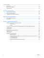
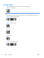
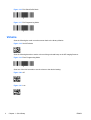
HP Imaging Barcode Scanner User Guide © 2010, 2011 Hewlett-Packard Development Company, L.P. Microsoft, Windows, and Windows Vista are either trademarks or registered trademarks of Microsoft Corporation in the United States and/or other countries. The only warranties for HP products and services are set forth in the express warranty statements accompanying such products and services. Nothing herein should be construed as constituting an additional warranty. HP shall not be liable for technical or editorial errors or omissions contained herein. This document contains proprietary information that is protected by copyright. No part of this document may be photocopied, reproduced, or translated to another language without the prior written consent of Hewlett-Packard Company. Second Edition (May 2011) Document Part Number: 634488-002 About This Guide This guide provides information on setting up and using the HP Imaging Barcode Scanner. WARNING! Text set off in this manner indicates that failure to follow directions could result in bodily harm or loss of life. CAUTION: Text set off in this manner indicates that failure to follow directions could result in damage to equipment or loss of information. NOTE: ENWW Text set off in this manner provides important supplemental information. iii iv About This Guide ENWW Table of contents 1 Quick Setup ..................................................................................................................................................... 1 OPOS Driver ........................................................................................................................................ 1 Carriage Return .................................................................................................................................... 2 Tab ....................................................................................................................................................... 3 Volume ................................................................................................................................................. 4 2 Product Features ............................................................................................................................................ 6 HP Imaging Barcode Scanner .............................................................................................................. 6 3 Safety and Maintenance ................................................................................................................................. 7 Ergonomic Recommendations ............................................................................................................. 7 4 Setting Up and Using the Scanner ................................................................................................................ 8 Connect/Disconnect Cable to Scanner ................................................................................................ 8 Using the Scanner ................................................................................................................................ 9 Configuring the Interface ..................................................................................................... 9 USB-COM ......................................................................................................... 10 Keyboard Interface ............................................................................................ 10 Scancode Tables .............................................................................................. 10 Country Mode .................................................................................................... 11 Installing the Stand ............................................................................................................................. 11 Use .................................................................................................................................... 12 Assembling the Stand ........................................................................................................ 13 Installation .......................................................................................................................... 13 Scanning Modes ................................................................................................................................. 14 Enable Stand Mode ........................................................................................................... 14 Enable Trigger Mode ......................................................................................................... 14 5 Programming the Scanner ........................................................................................................................... 15 Using Programming Bar Codes .......................................................................................................... 15 Configure Other Settings .................................................................................................................... 15 Resetting Standard Product Defaults ................................................................................................. 15 Reading Parameters .......................................................................................................................... 16 Aiming System ................................................................................................................... 16 Good Read Green Spot Duration ...................................................................................... 16 ENWW v 6 Operating Modes ........................................................................................................................................... 17 Scan Mode ......................................................................................................................................... 17 Multiple Label Reading ....................................................................................................................... 18 Stand Operation ................................................................................................................................. 18 Appendix A Troubleshooting .......................................................................................................................... 20 Solving Common Problems ................................................................................................................ 20 Online Technical Support ................................................................................................................... 20 Preparing to Call Technical Support ................................................................................................... 21 Appendix B Technical Specifications ............................................................................................................ 22 LED and Beeper Indications ............................................................................................................... 25 Error Codes ........................................................................................................................................ 26 Appendix C Agency Regulatory Notices ....................................................................................................... 27 Federal Communications Commission Notice ................................................................................... 27 Modifications ...................................................................................................................... 27 Cables ................................................................................................................................ 27 Declaration of Conformity for Products Marked with the FCC Logo (United States Only) ................. 27 Canadian Notice ................................................................................................................................. 28 Avis Canadien .................................................................................................................................... 28 European Union Regulatory Notice .................................................................................................... 28 Japanese Notice ................................................................................................................................. 29 Korean Notice ..................................................................................................................................... 29 Product Environmental Notices .......................................................................................................... 29 Materials Disposal ............................................................................................................. 29 Disposal of Waste Equipment by Users in Private Household in the European Union ..... 29 HP Recycling Program ...................................................................................................... 29 Chemical Substances ........................................................................................................ 30 Restriction of Hazardous Substances (RoHS) ................................................................... 30 vi ENWW 1 Quick Setup Use the bar codes in this chapter to perform quick setup procedures for common tasks. Scan the following bar code to set the scanner back to the factory defaults. Figure 1-1 Set All Defaults NOTE: Scanning the “Set All Defaults” bar code does not change the interface type. Scan the following bar code (USB HID Keyboard Emulation) in order to put the HP Imaging Barcode Scanner into the default mode of the scanner. Figure 1-2 USB HID Keyboard Emulation When the scanner is changed between HID and USB-COM mode, allow the Windows operating system a little time to reload the native drivers for the scanner. OPOS Driver The HP Imaging Barcode Scanner by default is shipped in the human interface device (HID) keyboard emulation mode. In order to use the barcode scanner with OLE for Retail POS (OPOS) drivers the scanner must be put into USB COM (OPOS) mode. For your convenience the bar code to put the HP Imaging Barcode Scanner into USB COM (OPOS) mode or into HID keyboard emulation are located in this document. Refer to the HP Imaging Barcode Scanner Product Reference Guide for complete list of barcodes. The document can be found on the HP Point of Sale System Software and Documentation CD that comes with the scanner or the softpaq that is located on the HP support web site. Scan the following bar code (USB COM OPOS) in order to put the HP Imaging Barcode Scanner into the mode to be used with the OPOS drivers. Figure 1-3 USB COM (OPOS) ENWW OPOS Driver 1 Carriage Return Scan the following bar code to set the scanner back to the factory defaults. Figure 1-4 Set All Defaults NOTE: Scanning the “Set All Defaults” bar code does not change the interface type. If a carriage return is required after each scanned bar code, scan the following bar codes in order: Figure 1-5 Enter Programming Mode Figure 1-6 Set Global Suffix Figure 1-7 0 Figure 1-8 D Figure 1-9 Exit Global Suffix Mode 2 Chapter 1 Quick Setup ENWW Figure 1-10 Exit Programming Mode Tab Scan the following bar code to set the scanner back to the factory defaults. Figure 1-11 Set All Defaults NOTE: Scanning the “Set All Defaults” bar code does not change the interface type. If a tab is required after each scanned bar code, scan the following bar codes in order: Figure 1-12 Enter Programming Mode Figure 1-13 Set Global Suffix Figure 1-14 0 Figure 1-15 9 ENWW Tab 3 Figure 1-16 Exit Global Suffix Mode Figure 1-17 Exit Programming Mode Volume Scan the following bar code to set the scanner back to the factory defaults. Figure 1-18 Set All Defaults Scan the following barcode to set the volume of the good read beep on the HP Imaging Scanner: Figure 1-19 Enter Programming Mode Scan one of the four barcodes to set the volume to the desired setting: Figure 1-20 Off Figure 1-21 Low 4 Chapter 1 Quick Setup ENWW Figure 1-22 Medium Figure 1-23 High Scan the following barcode to exit the programming mode. Figure 1-24 Exit Programming Mode ENWW Volume 5 2 Product Features HP Imaging Barcode Scanner With rich feature sets and extensive model options, the HP Imaging Barcode Scanner represents the premium level of data collection equipment for general purpose applications. The HP scanner has enhanced optics with improved motion tolerance, allowing codes placed on fast-moving objects to be easily and quickly captured, creating the ideal scanner for tasks requiring high throughput like those found in retail and light industrial environments. The scanner includes the following features: ● Omni-Directional Operation: To read a symbol or capture an image, simply aim the scanner and pull the trigger. The HP Imaging Barcode Scanner is a powerful omni-directional scanner, so the orientation of the symbol is not important. ● Intuitive Aiming System: The “Green Spot” for good-read feedback helps to improve productivity in noisy environments or in situations where silence is required. When using the product with the cradle at a 45° position, the aiming pattern can work as an aiming system to aid in positioning the bar code for quick and intuitive reading. ● 1D and 2D Symbol Decoding: Reliably decodes all standard 1D (linear) and 2D bar codes, including: ◦ GS1 DataBar™ linear codes ◦ Postal Codes (China Post) ◦ Stacked Codes (such as GS1 DataBar Expanded Stacked, GS1 DataBar Stacked, GS1 DataBar, Stacked Omnidirectional) The data stream — acquired from decoding a symbol — is rapidly sent to the host. The scanner is immediately available to read another symbol. 6 ● Imaging: The scanner can also function as a camera by capturing entire images or image portions of labels, signatures, and other items. ● Mobile Phone Scanning: The scanner is designed with enhanced motion tolerance and technology to optimize contrast levels. These features allow quick reading of barcodes off of mobile phones and PDAs. ● Handheld or Presentation Mode Operation: The scanner includes a stand that can be used for convenient storage or to allow the scanner to be used in presentation / hands-free mode. Chapter 2 Product Features ENWW 3 Safety and Maintenance Ergonomic Recommendations WARNING! In order to avoid or minimize the potential risk of ergonomic injury follow the recommendations below. Consult with your local Health & Safety Manager to ensure that you are adhering to your company’s safety programs to prevent employee injury. ● Reduce or eliminate repetitive motion ● Maintain a natural position ● Reduce or eliminate excessive force ● Keep objects that are used frequently within easy reach ● Perform tasks at correct heights ● Reduce or eliminate vibration ● Reduce or eliminate direct pressure ● Provide adjustable workstations ● Provide adequate clearance ● Provide a suitable working environment ● Improve work procedures CAUTION: The chemicals contained in Hepicide bacterial cleaners that are used in the retail market to reduce the risk and spread of bacterial disease from contaminated scanner surfaces may affect plastic structural properties and result in permanent failure of plastics under pressure. ENWW Ergonomic Recommendations 7 4 Setting Up and Using the Scanner Follow the steps below to connect and get the scanner up and communicating with its host. 1. Connect the Cable to the scanner and the Host. 2. Configure the Interface (refer to Configuring the Interface on page 9). 3. Configure the scanner as described in Programming the Scanner on page 15 (optional, depends on settings needed). Connect/Disconnect Cable to Scanner Figure 4-1 Connecting to the Scanner Figure 4-2 Connecting to the Host Host Connection: The scanner plugs directly into the host device as shown above. 8 Chapter 4 Setting Up and Using the Scanner ENWW Using the Scanner The scanner normally functions by capturing and decoding codes. It is equipped with an internal motion-sensing function that activates the aiming system on device motion. The intelligent aiming system indicates the field of view that should be positioned over the bar code: Figure 4-3 Aiming System Figure 4-4 Relative Size and Location of Aiming System Pattern A red beam illuminates the label. The field of view indicated by the aiming system will be smaller when the scanner is closer to the bar code and larger when it is farther from the code. Symbologies with smaller bars or elements (mil size) should be read closer to the unit. Symbologies with larger bars or elements (mil size) should be read farther from the unit. If the aiming system is centered and the entire bar code is within the aiming field, you will get a good read. Successful reading is signaled by an audible tone plus a good-read green spot LED indicator. Refer to the HP Imaging Barcode Scanner Product Reference Guide (PRG) for more information about this feature and other programmable settings. Configuring the Interface The scanner supports USB as a host interface. Programming options and information are provided in Configuring the Interface on page 9. Upon completing the physical connection between the scanner and its host, select the desired Interface option by scanning the appropriate bar code to select your system’s interface type. If you want to customize additional settings and features associated with that interface, proceed to the corresponding chapter in the HP Imaging Barcode Scanner PRG. NOTE: Unlike some other programming features and options, interface selections require that you scan only one programming bar code label. DO NOT scan an ENTER/EXIT barcode prior to scanning an interface selection bar code. Some interfaces require the scanner to start in the disabled state when powered up. If additional scanner configuration is desired while in this state, pull the trigger and hold for 5 seconds. The scanner will change to a state that allows programming with bar codes. ENWW Using the Scanner 9 USB-COM USB Com to simulate RS-232 standard interface Figure 4-5 Select USB-COM-STD NOTE: Install the correct USB Com driver from the CD included with your product. Keyboard Interface Select options for USB Keyboard Interfaces. USB Keyboard with alternate key encoding Figure 4-6 Select USB Alternate Keyboard USB Keyboard with standard key encoding Figure 4-7 Select USB Keyboard Scancode Tables See the HP Imaging Barcode Scanner Product Reference Guide (PRG) for information about control character emulation which applies to keyboard interfaces. 10 Chapter 4 Setting Up and Using the Scanner ENWW Country Mode This feature specifies the country/language supported by the keyboard. The following languages are supported: U.S. English Norwegian Korean UK English Spanish Russian Belgian Swedish Hebrew Danish Traditional Chinese Arabic French Thai Greek French Canadian Portuguese (EU) Hungarian German Brazilian Portuguese Slovakian Italian Japanese See the HP Imaging Barcode Scanner Product Reference Guide (PRG) for information and programming bar codes for this feature. Installing the Stand The stand for the HP Imaging Barcode Scanner is an operator-friendly device, ensuring a sure grip of the scanner when auto-sense scanning is required. ENWW Installing the Stand 11 Use Insert the scanner into the stand as shown below in Figure 4-8 (Figure 1). Adjust the scanner to the desired position for reading bar codes by bending the flexible tubing. Figure 4-8 Adjusting the Scanner 12 Chapter 4 Setting Up and Using the Scanner ENWW Assembling the Stand To assemble the components of the stand, refer to the Figure 4-9 (Figure 2) below. Figure 4-9 Stand Assembly 1. Place the metal Base Plate (2) and the Base Cover (3) together with the countersink in the Base Plate facing out. 2. Place one of the flat-head machine screws (1) through the Base Plate (2) and Cover (3). 3. Screw the Flex Tube (4) to the Base Plate (2) and Cover (3) making sure the notch in the Flex Tube (4) aligns with the ribs in the Base Cover (3) as shown in Figure 4-9 (Figure 3). Tighten firmly. 4. Place the Flex Tube Cover (5) over the Flex Tube (4). 5. Screw the Cup (6) to the Flex Tube using the second flat-head machine screw (1) making sure the notch in the Flex Tube (4) aligns with the ribs in the Cup (6) as shown in Figure 4-9 (Figure 4). Tighten firmly. 6. Select the appropriate bar code label [Laser or Imager (8)], peel off the backing and affix to the recess in the Base Cover (3). Installation Attachment with screws: ENWW 1. Make sure that the stand is properly assembled. 2. Fix the base of the stand to the desired surface with the three screws provided (7). 3. Adjust as needed. Installing the Stand 13 Freestanding: 1. Peel the three rubber pads (9) off the backing sheet and affix them to the recesses in the bottom side of the Base Cover. 2. Place the stand on any flat surface and adjust as needed. Scanning Modes Enable Stand Mode Enable Stand Mode programs the imager to operate in stand mode, where the scanner automatically senses and reads labels with no trigger pull required. Enable Trigger Mode Enable Trigger Mode programs the imager to operate in triggered mode, where the trigger needs to be pulled to initiate the reading of a label. 14 Chapter 4 Setting Up and Using the Scanner ENWW 5 Programming the Scanner The scanner is factory-configured with a set of standard default features. After scanning the interface bar code from the Interfaces section, select other options and customize the scanner through use of the programming bar codes available in the HP Imaging Barcode Scanner Product Reference Guide (PRG). Check the corresponding features section for your interface, and also the Data Editing and Symbologies chapters of the PRG. Using Programming Bar Codes This guide contains bar codes that allow you to reconfigure the scanner. Some programming bar code labels, like the "Standard Product Default Settings" in this chapter, require only the scan of that single label to enact the change. Other bar codes require the scanner to be placed in Programming Mode prior to scanning them. Scan an ENTER/EXIT bar code once to enter Programming Mode; scan the desired parameter settings; scan the ENTER/EXIT bar code again to accept your changes, which exits Programming Mode and returns the scanner to normal operation. Configure Other Settings Additional programming bar codes are available in the PRG to allow for customizing programming features. If your installation requires different programming than the standard factory default settings, refer to the PRG. Resetting Standard Product Defaults Reference the PRG for a listing of standard factory settings. If you aren’t sure what programming options are in the scanner, or you’ve changed some options and want the factory settings restored, scan the Standard Product Default Settings bar code below to copy the factory configuration for the currently active interface to the current configuration. NOTE: Factory defaults are based on the interface type. Configure the scanner for the correct interface before scanning this label. Figure 5-1 Standard Product Default Settings ENWW Using Programming Bar Codes 15 Reading Parameters Move the scanner toward the target and center the aiming pattern and illumination system to capture and decode the image. See Using the Scanner on page 9 for more information. The aiming system will briefly switch off after the acquisition time, and if no code is decoded will switch on again before the next acquisition. The illuminator will remain on until the symbol is decoded. As you read code symbols, adjust the distance at which you are holding the scanner. Aiming System A number of options for customizing control of the Aiming System are available. See the HP Imaging Barcode Scanner Product Reference Guide (PRG) for more information and programming bar codes. Good Read Green Spot Duration Successful reading can be signaled by a good read green spot. Use the bar codes that follow to specify the duration of the good read pointer beam after a good read. Figure 5-2 ENTER/EXIT PROGRAMMING MODE Figure 5-3 Disabled Figure 5-4 Short (300 ms) Figure 5-5 Medium (500 ms) Figure 5-6 Long (800 ms) 16 Chapter 5 Programming the Scanner ENWW 6 Operating Modes Scan Mode The imager can be set to operate in one of several scanning modes. See the HP Imaging Barcode Scanner Product Reference Guide (PRG) for more information and settings for any of the options: Trigger Single (Default): This mode is associated with typical handheld scanner operation. Motion Sense is active and if the scanner detects motion the aiming pattern is turned on. When the trigger is pulled, illumination is turned on and the scanner attempts to read a label. Scanning is activated until one of the following occurs: ● the programmable “maximum scan on time”1 has elapsed ● a label has been read ● the trigger is released Trigger Pulse Multiple: Scanning begins when the trigger is pulled and continues after the trigger is released, until the trigger is pulled again or until the programmable “maximum scan on time”1 has elapsed. Reading a label does not disable scanning. Double Read Timeout1 prevents undesired multiple reads while in this mode. Trigger Hold Multiple: When the trigger is pulled, scanning starts and the product scans until the trigger is released or “maximum scan on time”1 has elapsed. Reading a label does not disable scanning. Double Read Timeout1 prevents undesired multiple reads while in this mode. Always On — The illuminator is always ON and the scanner is always ready for code reading. Double Read Timeout1 prevents undesired multiple reads. Flashing — The scanner illuminator flashes on and off regardless of the trigger status. Code reading takes place only during the Flash On2 time. Double Read Timeout1 prevents undesired multiple reads. 1 See the PRG for these and other programmable features. 2 Controlled by Flash On Time and Flash Off Time. Use the PRG to program these options. Stand Mode: In Stand Mode, the illumination remains on for a configurable amount of time after a good read occurs. The scanner exits stand mode when movement is detected. If the trigger is activated from stand mode, the scanner transitions into one of the triggered modes. Pick Mode: Specifies a Decoding and Transmission process where bar codes that are not within the configurable distance from the center of the aiming pattern are not acknowledged or transmitted to the host. Pick Mode is active only while the scanner is in Trigger Single mode. If the scanner switches to a different Read Mode, Pick Mode is automatically disabled. Figure 6-1 ENTER/EXIT PROGRAMMING MODE ENWW Scan Mode 17 Figure 6-2 Scan Mode = Trigger Single Figure 6-3 Scan Mode = Trigger Pulse Multiple Figure 6-4 Scan Mode = Trigger Hold Multiple Figure 6-5 Scan Mode = Flashing Figure 6-6 Scan Mode = Always On Figure 6-7 Scan Mode = Stand Mode Figure 6-8 Pick Mode = Enabled Multiple Label Reading The scanner offers a number of options for multiple label reading. See the PRG or software configuration tool for descriptions of these features and programming labels. Stand Operation This feature controls how the scanner behaves when it is placed into a cradle or stand. 18 ● Ignore Autorecognition - Disables mode switching when the scanner is placed in a stand. ● Switch to Stand Mode - Automatically switches the scanner to Stand Mode when the scanner is placed in the stand. Chapter 6 Operating Modes ENWW ● Switch to Flashing - Automatically switches the scanner to Flash Mode when placed in the stand. ● Switch to Always On - Automatically switches the scanner to Always On mode when placed in the stand. Figure 6-9 ENTER/EXIT PROGRAMMING MODE Figure 6-10 Ignore Autorecognition Figure 6-11 Switch to Stand Mode Figure 6-12 Switch to Flashing Figure 6-13 Switch to Always On ENWW Stand Operation 19 A Troubleshooting Solving Common Problems The following table lists possible problems and recommended solutions. Problem Solution Scanner does not power up. Ensure that the POS computer is powered on. Ensure that the cable is properly connected to a USB port on the computer. Ensure that the cable is properly connected to the scanner. Move the cable to a different USB port on the computer. If still not working, replace the interface cable. Top light on scanner is flashing. Scanner does not read barcodes (scanner emits a target cross hair but there is no green dot or single beep when reading a barcode). Pull and hold the trigger until scanner emits a short set of beeps. Scan a USB interface type: 1. USB Com 2. USB Keyboard Wedge Try scanning a different product barcode. Clean the front window on the scanner if it is dirty. Check the front window on Scanner. If it is heavily damaged, replace the scanner. Determine the symbology type and ensure the symbology is enabled. Scanner emits a target cross, emits a green dot, and emits a single beep when reading a barcode but does not transmit data to the host. Reset the Interface option: USB Com or USB Keyboard Wedge ● If interface = USB Com , open a comport emulator and determine in Device Manager the correct comport number. ● If interface = USB Keyboard Wedge, open a generic text editor such as Notepad, Microsoft Word or Command prompt. Online Technical Support For the online access to technical support information, self-solve tools, online assistance, community forums or IT experts, broad multivendor knowledge base, monitoring and diagnostic tools, go to http://www.hp.com/support. 20 Appendix A Troubleshooting ENWW Preparing to Call Technical Support If you can not solve a problem using the troubleshooting tips in this section, you may need to call technical support. Have the following information available when you call: ENWW ● If the product is connected to an HP POS computer, provide the serial number of the POS computer ● Purchase date on invoice ● The spares part number located on the product ● Condition under which the problem occurred ● Error messages received ● Hardware configuration ● Hardware and software you are using Preparing to Call Technical Support 21 B Technical Specifications The following table contains physical and performance characteristics, user environment and regulatory information. Item Description Physical Characteristics Color Black Dimensions Height 7.1”/181 mm Length 3.9”/100 mm Width 2.8”/71 mm Weight (without cable) Approximately 6.9 ounces / 195.6 g Electrical Characteristics Voltage & Current Operating (typical) = 160 ma @ 5 vdc Operating (max) = 350 ma @ 5 vdc Idle/standby (typical) = 65 ma @ 5 vdc Input Voltage = 4.75 - 5.25 vdc Performance Characteristics Light Source LEDs Roll (Tilt) ± 180° Tolerance from normal Pitch Tolerance ± 40° Skew (Yaw) ± 40° Minimum Element Width 4 mil (1D Linear and HD) 5 mil (PDF-417) 6 mil (DataMatrix) Print Contrast Minimum 25% minimum reflectance Depth of Field (Typical)1 Symbology SR: HD: Code 39 5mil: 1.6” - 7.5” (4 - 19cm); 5mil: 1.2” - 3” (3 - 7.5cm) 10mil: 0.4” - 11.8” (1.0 - 30cm); 10mil: 0.4” - 3.1” (1 - 8cm) 20mil: up to 17.7” (45cm) EAN 22 Appendix B Technical Specifications 13mil: 0.6” - 15.7” (1.5 - 40cm); 13mil: 0.8” - 5.1” (2 - 13cm); 7.5mil: 0.5 - 10.6” (2.0 - 27cm) 7.5mil: 0 - 3.7” (0 - 9.5cm) ENWW Depth of Field (Typical)1 Symbology SR: HD: PDF-417 6.6mil: 11.0” - 5.9” (2.5 - 15cm); 4mil: 1” - 2.6” (2.5 - 6.5cm); 10mil: 0.2” - 8.6” (0.5 - 22cm); 6.6mil: .2” to 3.5” (0.5 - 9cm); 15mil: 0.6” - 13.4” (1.5 - 34cm) 10mil: 0 to 4.3” (0 - 11cm) 10mil: 0.8” to 6.3” (2.0 - 16cm) 5mil: 1.6” to 2.2” (4.0 - 5.5cm) DataMatrix 15mil: 0” to 9.3” (0 - 23.6cm) QR Code 10mil: 1.2” to 4.9” (3 - 12.5cm) 6.7mil: 1” to 2.4” (2.5 - 6.0cm) 15mil: 0” to 7.5” (1 - 19.0cm) 13 mils DOF based on EAN. All other 1D codes are Code 39. All labels grade A, typical environmental light, 20°C, label inclination 10°. 1 Decode Capability 1D Bar Codes ● UPC/EAN/JAN (A, E, 13, 8) ● Code 128 ISBT ● Code 93 ● UPC/EAN/JAN (including P2 /P5) ● Interleaved 2 of 5 ● MSI ● UPC/EAN/JAN (including; ISBN / Bookland & ISSN) ● Standard 2 of 5 ● PZN ● Interleaved 2 of 5 CIP (HR) ● Plessey ● UPC/EAN Coupons; Code 39 (including full ASCII) ● Industrial 2 of 5 ● Anker Plessey ● Code 39 Trioptic ● Discrete 2 of 5 ● Follet 2 of 5 ● Code39 CIP (French Pharmaceutical) ● Datalogic 2 of 5 (China Post Code/ Chinese 2 of 5) ● GS1 DataBar Omnidirectional ● GS1 DataBar Limited ● LOGMARS (Code 39 w/ standard check digit enabled) ● IATA 2 of 5 Air cargo code ● GS1 DataBar Expanded ● Code 11 ● Danish PPT ● GS1 DataBar Truncated ● Codabar ● Code 32 (Italian Pharmacode 39) ● DATABAR Expanded Coupon ● Codabar (NW7) ● Code 128 ● ABC Codabar 2D / Stacked Codes The scanner is capable of decoding the following sybmologies using multiple frames (i.e. Multi-Frame Decoding): ENWW 23 ● PDF-417 ● Aztec ● PDF-417 ● QR Code ● Sweden Post ● MacroPDF ● Aztec ● Portugal Post ● Micro PDF417 ● Datamatrix ● LaPoste A/R 39 ● GS1 Composites (1 - 12) ● Inverse Datamatrix ● 4-State Canada ● Codablock F ● Datamatrix is configurable for the following parameters: ● Postal Codes ● French CIP13a ● Australian Post ● GS1 DataBar Stacked ● Japanese Post ● ● KIX Post GS1 DataBar Stacked Omnidirectional ● Planet Code ● GS1 DataBar Expanded Stacked ● GSI Databar Composites ● Chinese Sensible Code ● Inverted 2D codesb ◦ Normal or Inverted ◦ Square or Rectangular Style ◦ Data length (1 - 3600 characters) ● Maxicode ● Postnet ● QR Codes (QR, Micro QR and Multiple QR Codes) ● Royal Mail Code (RM45CC) ● Intelligent Mail Barcode (IMB) a It is acceptable to handle this with ULE. b The SW can apply the Normal/Reverse Decoding Control to the following symbologies: Datamatrix, QR, Micro QR, Aztec and Chinese Sensible Code. Interfaces Supported USB Com Std., USB Keyboard, USB (see Configuring the Interface on page 9 for a listing of available interface options) User Environment Operating Temperature 32° to 131° F (0° to 55° C) Storage Temperature -4° to 158° F (-20° to 70° C) Humidity Operating: 5% to 90% relative humidity, non-condensing Drop Specifications Scanner withstands 18 drops from 1.8 meters (6.0 feet) to concrete Ambient Light Immunity Up to 100,000 Lux Contaminants Spray/rain Dust/particulates IEC 529-IP52 ESD Level 16 KV Regulatory Laser Safety 24 Appendix B Technical Specifications IEC Class 2 ENWW LED and Beeper Indications The scanner’s beeper sounds and its LED illuminates to indicate various functions or errors on the scanner. An optional “Green Spot” also performs useful functions. The following tables list these indications. One exception to the behaviors listed in the tables is that the scanner’s functions are programmable, and so may or may not be turned on. For example, certain indications such as the power-up beep can be disabled using programming bar code labels. 1 Indicator Description LED Beeper Power-up Beep The scanner is in the process of powering-up. Good Read Beep A label has been successfully scanned by the scanner. LED behavior for this indication is configurable via the feature “Good Read: When to Indicate” (see the PRG for information). The scanner will beep once at current frequency, volume, mono/bitonal setting and duration upon a successful label scan. ROM Failure There is an error in the scanner's software/ programming. Flashes Scanner sounds one error beep at highest volume. Limited Scanning Label Read Indicates that a host connection is not established. N/A Scanner 'chirps' six times at the highest frequency and current volume. Scanner Active Mode The scanner is active and ready to scan. The LED is lit steadily1 N/A Scanner Disabled The scanner has been disabled by the host. The LED blinks continuously N/A Green Spot1 flashes momentarily Upon successful read of a label, the software shall turn the green spot on for the time specified by the configured value. N/A N/A Image Capture When ready to capture image Blue light flashes 2 times when updating N/A Scanner beeps four times at highest frequency and volume upon power-up. Except when in sleep mode or when a Good Read LED Duration other than 00 is selected Programming Mode - The following indications ONLY occur when the scanner is in Programming Mode. ENWW INDICATION DESCRIPTION LED BEEPER Label Programming Mode Entry A valid programming label has been scanned. LED blinks continuously Scanner sounds four low frequency beeps. Label Programming Mode Rejection of Label A label has been rejected. N/A Scanner sounds three times at lowest frequency and current volume. LED and Beeper Indications 25 INDICATION DESCRIPTION LED BEEPER Label Programming Mode Acceptance of Partial Label In cases where multiple labels must be scanned to program one feature, this indication acknowledges each portion as it is successfully scanned. N/A Scanner sounds one short beep at highest frequency and current volume. Label Programming Mode Acceptance of Programming Configuration option(s) have been successfully programmed via labels and the scanner has exited Programming Mode. N/A Scanner sounds one high frequency beep and 4 low frequency beeps followed by reset beeps. Label Programming Mode Cancel Item Entry Cancel label has been scanned. N/A Scanner sounds two times at low frequency and current volume. Error Codes Upon startup, if the scanner sounds a long tone, this means the scanner has not passed its automatic Selftest and has entered FRU (Field Replaceable Unit) isolation mode. If the scanner is reset, the sequence will be repeated. Press and release the trigger to hear the FRU indication code. The following table describes the LED flashes/beep codes associated with an error found. 26 Number of LED Flashes/Beeps Error Corrective Action 1 Configuration Contact Help desk for assistance 2 Interface PCB Contact Help desk for assistance 6 Digital PCB Contact Help desk for assistance 11 Imager Contact Help desk for assistance Appendix B Technical Specifications ENWW C Agency Regulatory Notices Federal Communications Commission Notice This equipment has been tested and found to comply with the limits for a Class B digital device, pursuant to Part 15 of the FCC Rules. These limits are designed to provide reasonable protection against harmful interference in a residential installation. This equipment generates, uses, and can radiate radio frequency energy and, if not installed and used in accordance with the instructions, may cause harmful interference to radio communications. However, there is no guarantee that interference will not occur in a particular installation. If this equipment does cause harmful interference to radio or television reception, which can be determined by turning the equipment off and on, the user is encouraged to try to correct the interference by one or more of the following measures: ● Reorient or relocate the receiving antenna. ● Increase the separation between the equipment and the receiver. ● Connect the equipment into an outlet on a circuit different from that to which the receiver is connected. ● Consult the dealer or an experienced radio or television technician for help. Modifications The FCC requires the user to be notified that any changes or modifications made to this device that are not expressly approved by Hewlett Packard Company may void the user's authority to operate the equipment. Cables Connections to this device must be made with shielded cables with metallic RFI/EMI connector hoods to maintain compliance with FCC Rules and Regulations. Declaration of Conformity for Products Marked with the FCC Logo (United States Only) This device complies with Part 15 of the FCC Rules. Operation is subject to the following two conditions: 1. This device may not cause harmful interference. 2. This device must accept any interference received, including interference that may cause undesired operation. For questions regarding the product, contact: Hewlett Packard Company P. O. Box 692000, Mail Stop 530113 Houston, Texas 77269-2000 Or, call 1-800-HP-INVENT (1-800 474-6836) ENWW Federal Communications Commission Notice 27 For questions regarding this FCC declaration, contact: Hewlett Packard Company P. O. Box 692000, Mail Stop 510101 Houston, Texas 77269-2000 Or, call (281) 514-3333 To identify this product, refer to the Part, Series, or Model number found on the product. Canadian Notice This Class B digital apparatus meets all requirements of the Canadian Interference-Causing Equipment Regulations. Avis Canadien Cet appareil numérique de la classe B respecte toutes les exigences du Règlement sur le matériel brouilleur du Canada. European Union Regulatory Notice Products bearing the CE marking comply with the following EU Directives: ● Low Voltage Directive 2006/95/EC ● EMC Directive 2004/108/EC ● Ecodesign Directive 2009/125/EC, where applicable CE compliance of this product is valid if powered with the correct CE-marked AC adapter provided by HP. Compliance with these directives implies conformity to applicable harmonized European standards (European Norms) that are listed in the EU Declaration of Conformity issued by HP for this product or product family and available (in English only) either within the product documentation or at the following web site: http://www.hp.eu/certificates (type the product number in the search field). The compliance is indicated by one of the following conformity markings placed on the product: For non-telecommunications products and for EU harmonized telecommunications products, such as Bluetooth® within power class below 10mW. For EU non-harmonized telecommunications products (If applicable, a 4-digit notified body number is inserted between CE and !). Please refer to the regulatory label provided on the product. The point of contact for regulatory matters is: Hewlett-Packard GmbH, Dept./MS: HQ-TRE, Herrenberger Strasse 140, 71034 Boeblingen, GERMANY. 28 Appendix C Agency Regulatory Notices ENWW Japanese Notice Korean Notice Product Environmental Notices Materials Disposal Some HP LCD monitors contain mercury in the fluorescent lamps that might require special handling at end-of-life. Disposal of this material can be regulated because of environmental considerations. For disposal or recycling information, contact the local authorities or the Electronic Industries Alliance (EIA) http://www.eiae.org. Disposal of Waste Equipment by Users in Private Household in the European Union This symbol on the product or on its packaging indicates that this product must not be disposed of with your household waste. Instead, it is your responsibility to dispose of your waste equipment by handing it over to a designated collection point for the recycling or waste electrical and electronic equipment. The separate collection and recycling of your waste equipment at the time of disposal will help to conserve natural resources and ensure that it is recycled in a manner that protects human health and the environment. For more information about where you can drop off your waste equipment for recycling, please contact the local city office, the household waste disposal service or the shop where you purchased the product. HP Recycling Program HP encourages customers to recycle used electronic hardware, HP original print cartridges, and rechargeable batteries. For more information about recycling programs, go to http://www.hp.com/ recycle. ENWW Japanese Notice 29 Chemical Substances HP is committed to providing our customers with information about the chemical substances in our products as needed to comply with legal requirements such as REACH (Regulation EC No 1907/2006 of the European Parliament and Council). A chemical information report for this product can be found at http://www.hp.com/go/reach. Restriction of Hazardous Substances (RoHS) A Japanese regulatory requirement, defined by specification JIS C 0950, 2005, mandates that manufacturers provide Material Content Declarations for certain categories of electronic products offered for sale after July 1, 2006. To view the JIS C 0950 material declaration for this product, visit http://www.hp.com/go/jisc0950. 30 Appendix C Agency Regulatory Notices ENWW ᴹ∂ᴹᇣ⢙䍘઼ݳ㍐৺ަਜ਼䟿㺘 ṩᦞѝഭⲴlj⭥ᆀؑӗ૱⊑ḃ᧗ࡦ㇑⨶࣎⌅NJ ѱᶵ༺⨼ಞૂ ᮙ✣ಞ ᆎᶗ I/O PCAs ⭫Ⓠ 䭤ⴎ 啖ḽ ᵰެԌ 伄 䜞ཌ䜞։ 䰻䈱䇴༽ ཌ䜞䇴༽ ⭫㔼 ⺢ⴎ傧ࣞಞ ᱴ⽰ኅ O: 㺞⽰䈛ᴿ∈ᴿᇩ⢟䍞൞䈛䜞Ԭᡶᴿൽ䍞ᶆᯏѣⲺ䠅ൽ൞SJ/T11363-2006 ḽ㿺ᇐⲺ䲆䠅㾷≸ԛсȾ X: 㺞⽰䈛ᴿ∈ᴿᇩ⢟䍞㠩ቇ൞䈛䜞ԬⲺḆжൽ䍞ᶆᯏѣⲺ䠅䎻࠰ SJ/T11363-2006ḽ㿺ᇐⲺ䲆䠅㾷≸Ⱦ 㺞ѣḽᴿćXĈⲺᡶᴿ䜞Ԭ䜳ㅜਾ⅝ⴕRoHS⌋㿺ć⅝⍨䇤Րૂ⅝ⴕ⨼ӁՐ 2003ᒪ1ᴾ27ᰛީӄ⭫ᆆ⭫ಞ䇴༽ѣ䲆ֵ⭞Ḇӑᴿᇩ⢟䍞Ⲻ2002/95/EC ਭԚĈȾ ⌞φ⧥ֵؓ⭞ᵕ䲆Ⲻ৸㘹ḽ䇼ߩӄӝ↙ᑮᐛ֒Ⲻᓜૂ⒵ᓜㅿᶗԬȾ ENWW Product Environmental Notices 31