1
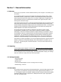
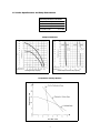
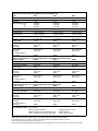
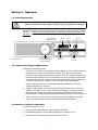
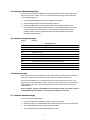
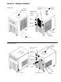
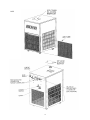
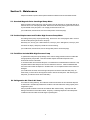
Operators Manual
Refrigerated Recirculating Chillers
Powerful Cooling
Microprocessor Controller
Digital Set & Read with
High Flow Centrifugal Pump,
Positive Displacement Pump or
Turbine Pump
110-116 rev. D
ecn 1390
Table of Contents
Section 1 - General Information
1.1
1.2
1.3
1.4
1.5
Warranty
Unpacking
Package Contents
Description
Specifications and Pump Performance
Section 2 - Set Up
2.1
2.2
2.3
2.4
2.5
Location
Reservoir Fluids
Pump, Hoses and Couplings
Setting Up a Closed System or Cooling Coil to the Chiller
Setting Up an Open Bath System to the Chiller
Section 3 - Operation
3.1
3.2
3.3
3.4
3.5
3.6
3.7
Power Requirements
Temperature Setting and Adjustments
Selection of Celsius or Fahrenheit
Setting the Readout High Limit
Controller Display Messages
Draining the Unit
Controller Default Settings
Section 4 - Diagram of Models
Section 5 - Maintenance
5.1
5.2
5.3
5.4
Standard Magnetic Drive Centrifugal Pump Motor
Positive Displacement High Pressure Pump Motor
Fluid Filter Included With High Pressure Pump
Refrigeration Air Vents & Air Filter
Section 6 - Troubleshooting
6.1
6.2
6.3
6.4
Unit Disabled
No Pumping
Insufficient Pumping
No Cooling or Insufficient Cooling
Section 7 - Service and Technical Support
Section 8 - Replacement Parts
This symbol marks chapters and sections of
this instruction manual which are particularly
relevant to safety.
When attached to the unit, this symbol draws
attention to the relevant section of the
instruction manual.
This symbol indicates hazardous voltages
may be present.
2
Section 1 - General Information
1.1 Warranty
Thank you for your purchase. We are confident it will serve you for a long time. Our warranty to you
is as follows:
The manufacturer agrees to correct for the original user of this product, either by repair, or at the
manufacturer’s election, by replacement, any defect which develops after delivery of this product
within the period as stated on the warranty card. In the event of replacement, the replacement unit
will be warranted for 90 days or warranted for the remainder of the original unit’s parts or labor
warranty period, whichever is longer.
If this product should require service, contact the manufacturer/suppliers’ office for instructions. When
return of the product is necessary, a return authorization number will be assigned and the product
should be shipped, transportation charges pre-paid, to the indicated service center. To insure prompt
handling, the return authorization number should be placed on the outside of the package and a
detailed explanation of the defect enclosed with the item.
This warranty shall not apply if the defect or malfunction was caused by accident, neglect,
unreasonable use, improper service, or other causes not arising out of defects in material or
workmanship. There are no warranties, expressed or implied, including, but not limited to, those of
merchantability or fitness for a particular purpose which extends beyond the description and period
set forth herein. The manufacturer’s sole obligation under this warranty is limited to the repair or
replacement of a defective product and the manufacturer shall not, in any event, be liable for any
incidental or consequential damages of any kind resulting from use or possession of this product.
Some states do not allow: (A) limitations on how long an implied warranty lasts or (B) the exclusion or
limitation of incidental or consequential damages, so the above limitations or exclusions may not
apply to you. This warranty gives you specific legal rights. You may have other rights which vary
from state to state.
1.2 Unpacking
Your recirculating chiller is shipped in a special carton. Retain the carton and all packing materials
until the unit is completely assembled and working properly. Set up and run the unit immediately to
confirm proper operation. Beyond one week, your unit may be warranty repaired, but not replaced. If
the unit is damaged or does not operate properly, contact the transportation company, file a damage
claim, then contact the company where your unit was purchased.
1.3 Package Contents
– Recirculating Chiller
– Operators Manual
– Warranty Card
– 2 sets of Inlet/Outlet Adapters: 1/2 inch I.D. tubing; 5/8 inch I.D. tubing
– Durable Tubing, 1/2 inch I.D.
1.4 Description
These chillers provide cooling power for demanding applications, and economically replace tap water
cooling systems. All models have a microprocessor controller, digital set/read and readout in °C or
°F. The refrigeration system has modulation capability to provide cooling as needed and thus greater
temperature stability and longer compressor life. Wetted parts are brass, copper, polypropylene,
PVC, nylon and stainless steel.
3
1.5 Chiller Specifications and Pump Performance
General Specifications To All Chillers
Temperature Setability
± 0.1°C
Temperature Uniformity
± 0.5°C
Readout Selectability
°C or °F
1/ inch NPT
2
Pump Inlet & Outlet
Pump Performance
1/
2
1/
3
1/
4
HP
HP
HP
Positive Displacement Pump Capacity
Centrifugal Pump Capacity
Comparison of Pump Options
4
1 HP
3 / HP
4
6000 Series Standard Chillers with Magnetic Drive Centrifugal Pump
Model
6205
6305
Operating Temperature
6505
Compressor
-5° to 40°C
1/
4 hp
-5° to 40°C
1/
3 hp
-10° to 40°C
1/
2 hp
Cooling Capacity @ 20°C
10°C
0°C
750 Watts
450 Watts
100 Watts
1200 Watts
825 Watts
375 Watts
1320 Watts
1055 Watts
550 Watts
Pressure at 0 Flow Rate
10 psi
10 psi
10 psi
Flow Rate @ 0 psi
4.3 gpm / 16.3 lpm
4.3 gpm / 16.3 lpm
4.3 gpm / 16.3 lpm
Reservoir Capacity
1.65 gal / 6.25 liters
1.65 gal / 6.25 liters
1.65 gal / 6.25 liters
Dimensions
hxwxd
24 x 14 3/8 x 26 1/2
61 x 36.5 x 67.3
24 x 14 3/8 x 26 1/2
61 x 36.5 x 67.3
24 x 14 3/8 x 26 1/2
61 x 36.5 x 67.3
(in.)
(cm)
Shipping Weight
155 lbs
165 lbs
170 lbs
Volts, Hz, Amps
Volts Range
60Hz Cat. No.
120V, 60Hz, 6.8A
108V to 132V
080501
120V, 60Hz, 8A
108V to 132V
080511
120V, 60Hz, 13A
108V to 132V
080521
Volts, Hz, Amps
Volts Range
Over Voltage: Category II
50Hz Cat. No.
240V, 50Hz, 3.4A
198V to 264V
240V, 50Hz, 4A
198V to 264V
240V, 50Hz, 6.5A
198V to 264V
080506
080516
080526
Additional Specifications for "P" Series 6000 Chillers with Positive Displacement Pump
Model "P" Series
6205P
6305P
6505P
Flow Rate @ 0 psi
1 gpm / 3.8 lpm
1 gpm / 3.8 lpm
1 gpm / 3.8 lpm
Pump Pressure (Adjustable)
20 to 100psi
20 to 100psi
20 to 100psi
Shipping Weight
160 lbs
170 lbs
170 lbs
Volts, Hz, Amps
Volts Range
60Hz Cat. No.
120V, 60Hz, 9.6A
108V to 132V
080502
120V, 60Hz, 10.8A
108V to 132V
080512
120V, 60Hz, 15.8A
108V to 132V
080522
Volts, Hz, Amps
Volts Range
Over Voltage: Category II
50Hz Cat. No.
240V, 50Hz, 4.8A
198V to 264V
240V, 50Hz, 5.4A
198V to 264V
240V, 50Hz, 8A
198V to 264V
080507
080517
080527
Additional Specifications for "T" Series 6000 Chillers with Turbine Pump
Model "T" Series
6205T
6305T
6505T
Flow Rate @ 0 PSI
3.5 gpm / 13.2 lpm
3.5 gpm / 13.2 lpm
3.5 gpm / 13.2 lpm
Pump Pressure (Adjustable)
20 to 100psi
20 to 100psi
20 to 100psi
Volts, Hz, Amps
Volts Range
60Hz Cat. No.
120V, 60Hz, 9.6A
108V to 132V
080503
120V, 60Hz, 10.8A
108V to 132V
080513
120V, 60Hz, 15.8A
108V to 132V
080523
Volts, Hz, Amps
Volts Range
Over Voltage: Category II
50Hz Cat. No.
240V, 50Hz, 4.8A
198V to 264V
240V, 50Hz, 5.4A
198V to 264V
240V, 50Hz, 8A
198V to 264V
080508
080518
080528
Environmental Conditions • Indoor Use Only
• Maximum Altitude : 2000 meter
• Relative Humidity : 80% for temperatures to 30°C
• Class 1 : Residential, Commercial, Light Industrial
• Operating Ambient : 5° to 30°C
• Pollution Degree : 2
• Class 2 : Heavy Industrial
Notes: Refer to the serial number plate on rear of the chiller for model and electrical data.
Cooling Capacity, Watts x 3.41 = BTUs/hr. Performance specifications determined at ambient temperature of 20°C/68°F.
For 50Hz models, derate cooling capacity and pump flow by 17%.
External Pressure Reducing Assembly (for Positive Displacement Pump models) Steps down high outlet pressure to 10 to 45 psi. Cat. No 060302
5
6000 Series Standard Chillers with Magnetic Drive Centrifugal Pump
Model
6705
6105
6155
Operating Temperature
-15° to 40°C
3/
4 hp
-15° to 40°C
+5° to 35°C
1 hp
11/2 hp
Cooling Capacity
@20°C 2500 Watts
@10°C 1700 Watts
@ 0°C 760 Watts
@20°C 2850 Watts
@10°C 1925 Watts
@ 0°C 940 Watts
@20°C 5200 Watts
@10°C 3600 Watts
@ 5°C 2700 Watts
Pressure at 0 Flow Rate
10 psi
10 psi
10 psi
Flow Rate @ 0 psi
4.3 gpm / 16.3 lpm
4.3 gpm / 16.3 lpm
4.3 gpm / 16.3 lpm
Reservoir Capacity
1.65 gal / 6.25 liters
1.65 gal / 6.25 liters
6.25 gal / 23.65 liters
Compressor
Dimensions
hxwxd
(in.)
(cm)
14 3/8
26 1/2
14 3/
26 1/2
24 x
x
61 x 36.5 x 67.3
24 x
8x
61 x 36.5 x 67.3
30 x 21x 27
76.2 x 53.3 x 68.6
Shipping Weight
178 lbs
178 lbs
450 lbs
Volts, Hz, Amps
Volts Range
60Hz Cat. No.
208-230V, 60Hz, 7.5A
187V to 253V
080531
208-230V, 60Hz, 8A
187V to 253V
080542
208-230V, 60Hz, 12A
187V to 253V
080593
Volts, Hz, Amps
Volts Range
Over Voltage: Category II
50Hz Cat. No.
240V, 50Hz, 7.5A
198V to 264V
240V, 50Hz, 8.5A
198V to 264V
240V, 50Hz, 12A
198V to 264V
080536
080546
080594
Additional Specifications for "P" Series 6000 Chillers with Positive Displacement Pump
Model "P" Series
6705P
6105P
6155P
Flow Rate @ 0 psi
4 gpm / 15.2 lpm
4 gpm / 15.2 lpm
4 gpm / 15.2 lpm
Pump Pressure (Adjustable)
20 to 100psi
20 to 100psi
20 to 100psi
Shipping Weight
178 lbs
178 lbs
450 lbs
Volts, Hz, Amps
Volts Range
60Hz Cat. No.
208-230V, 60Hz, 10A
187V to 253V
080532
208-230V, 60Hz, 11A
187V to 253V
080544
208-230V, 60Hz, 12A
187V to 253V
080596
Volts, Hz, Amps
Volts Range
Over Voltage: Category II
50Hz Cat. No.
240V, 50Hz, 10A
198V to 264V
240V, 50Hz, 11A
198V to 264V
240V, 50Hz, 12A
198V to 264V
080537
080547
080597
Additional Specifications for "T" Series 6000 Chillers with Turbine Pump
Model "T" Series
6705T
6105T
6155T
Flow Rate @ 0 PSI
3.5 gpm / 13.2 lpm
3.5 gpm / 13.2 lpm
3.5 gpm / 13.2 lpm
Pump Pressure (Adjustable)
20 to 100psi
20 to 100psi
20 to 100psi
Volts, Hz, Amps
Volts Range
60Hz Cat. No.
208-230V, 60Hz, 9.6A
108V to 132V
080533
208-230V, 60Hz, 10.8A
108V to 132V
080543
208-230V, 60Hz, 12A
187V to 253V
080598
Volts, Hz, Amps
Volts Range
Over Voltage: Category II
50Hz Cat. No.
240V, 50Hz, 9.6A
198V to 264V
240V, 50Hz, 10.8A
198V to 264V
240V, 50Hz, 12A
198V to 264V
080538
080548
080599
Environmental Conditions
• Indoor Use Only
• Maximum Altitude : 2000 meter
• Relative Humidity : 80% for temperatures to 30°C
• Class 1 : Residential, Commercial, Light Industrial
• Operating Ambient : 5° to 30°C
• Pollution Degree : 2
• Class 2 : Heavy Industrial
Notes: Refer to the serial number plate on rear of the chiller for model and electrical data.
Cooling Capacity, Watts x 3.41 = BTUs/hr. Performance specifications determined at ambient temperature of 20°C/68°F.
For 50Hz models, derate cooling capacity and pump flow by 17%.
External Pressure Reducing Assembly (for Positive Displacement Pump models) Steps down high outlet pressure to 10 to 45 psi. Cat. No 060302
6
Section 2 - Set Up
Before proceeding, be sure all power is off
2.1 Location
Locate the chiller on a strong, level surface. Insure easy access to the top cover and position
the chiller for unobstructed air flow through the front and rear screens. The front wheels can be
locked to keep the chiller in place while in use. Avoid voltage drops by using properly grounded
power outlets wired with 14 gauge or larger diameter wire. If possible, be close to the power
distribution panel. Minimize low line voltage problems by eliminating the use of extension cords.
2.2 Reservoir Fluids
For most applications above +15°C, distilled water is satisfactory. For operation below +15°C, the
chiller MUST be protected with an antifreeze solution. Ethylene glycol (laboratory grade) and water
in a 50/50 mixture is satisfactory from +15°C to -15°C. Select a fluid that is compatible with the
chiller's wetted parts of brass, copper, polypropylene, PVC, nylon and stainless steel. Only use fluids
that will satisfy safety, health and equipment compatibility requirements. CAUSTIC, CORROSIVE
OR FLAMMABLE FLUIDS MUST NEVER BE USED.
Do not use a flammable fluid as a fire hazard may result.
WARNING!
Operation below +15°C requires antifreeze in the circulating fluid.
2.3 Pump, Hoses and Couplings
To maintain a safe workplace and to avoid leaks, special care should be taken when choosing hoses
and connectors for the chiller.
1.
Pressure ratings - Hoses should be able to withstand the largest pressure that they will
encounter. For positive displacement pump models, this is 100 psi.
2.
Flexible tubing - Avoid tubing that will expand and take up fluid volume when operating at the
desired pressure.
3.
Hose diameter - The fittings on the chiller Outlet and Inlet lines are internally threaded,
1/2 inch I.D. N.P.T. The 2 adapters sets supplied are for 1/2 inch I.D. tubing and 5/8 inch I.D.
tubing. Other fittings can be used if a smaller hose diameter is desired. Remember that the
operating pressure in the circulating system increases when using a smaller diameter hose.
4.
Couplings & Clamps - The use of screw-tightened hose clamps is necessary on all joints to
insure good, tight connections. Quick connectors are not recommended because they have the
potential for restricting flow rate.
7
IMPORTANT!
Chillers equipped with a high pressure positive displacement pump have a pressure
regulator inside of the chiller and a pressure gauge on the control panel. To access this
regulator, remove the rear air grille. The valve is located to the right. On models 6107 & 6705,
6155 the regulator is located center point, upper grille (rear).
The Pressure Valve is FACTORY ADJUSTED to 40psi. If you do NOT want to operate at this
pressure, or do not know what your operating pressure should be, start at a lower operating
pressure. Reduce the pressure by turning the valve counterclockwise (unscrew outward)
before starting the chiller.
With the chiller fully connected and running, read the pressure gauge and turn the regulator
to the desired pressure. If required, an optional external pressure reducing assembly is
available for this pump to reduce the pressure to 10 - 45 psi.
2.4 Setting Up a Closed System or Cooling Coil to the Chiller
1.
Connect your closed cooling system to the chiller with hoses or pipes. The direction of the flow
through the system can be controlled by the way the hoses or pipes are connected to the chiller.
The “Inlet” will draw liquid into the chiller; the “Outlet” will pump liquid out.
2.
Turn the access panel screws to remove the top cover and expose the reservoir. Turn the filler
cap and lift up to remove. Use a funnel to fill the reservoir with fluid. When full, remove the
funnel, but do not replace the cap at this time. Check hoses and fittings for tightness and be
sure there are no bends or crimps in the hoses.
3.
Plug the chiller into the proper AC outlet (unit's electrical requirements on rear of unit). Press
the POWER ON button. The chiller will begin pumping liquid through your system. Check for
leaks.
4.
With the pump running, the reservoir's fluid level will decrease as the closed system begins to fill.
Add a little fluid at a time until the level in the reservoir stops going down. This means that your
system is filled and the air has been purged from it. Replace the reservoir cap and turn it
clockwise to lock it. Recheck the cap for tightness.
Note: When chillers with the standard magnetic drive centrifugal pump are connected to an external
apparatus with a built-in flow shut-off, an external bypass loop assembly (pt.# 510-147) may be
needed if operating below 20°C. This bypass assembly continues fluid circulation to and from the
pump even though the main flow to the external apparatus has been blocked.
2.5 Setting Up an Open Bath System to the Chiller
1.
Connect hoses to the Inlet and Outlet fittings on the back of the chiller. The "Inlet" draws fluid
into the chiller, the "Outlet" pumps fluid out. Fill the open bath. Considering this flow, position
the hoses in your bath for a good circular flow and stirring motion.
2.
Turn the panel screws to remove the top cover and access the reservoir. Turn and lift the filler
cap to remove. Use a funnel to fill the reservoir with the same fluid in your bath. This primes the
pump and helps establish a flow when the chiller is turned on.
3.
Replace the reservoir cap and turn to lock it. Check for tightness. Check all hoses and fittings.
Be sure there are no bends or crimps in the hoses, and that the hose attached to the chiller's
inlet is submerged near the bottom of the bath. Secure the inlet and outlet hoses to the open
tank so they do not move when pumping starts. The bath's fluid level will drop slightly as the
hoses in the system fill up with fluid. The bath's fluid must cover the chiller's inlet hose.
4.
Plug the unit into the proper AC outlet (unit's electrical requirements on rear of unit). Press the
Power On button. The chiller will begin pumping fluid through your system. Check for leaks.
8
Section 3 - Operation
3.1 Power Requirements
Caution! Be sure that the power supply is the same voltage as specified on the nameplate
With the chiller plugged in (before pressing the POWER ON button), the display responds by showing
standby (....). If there is no response, check that the circuit breaker on the rear of the chiller is in the
ON position. An extension cord is not recommended.
(For models with
optional heater only)
PRESSURE GAUGE,
Front Face Plate
(On Positive Displacement
Pump models only)
LED
DISPLAY
°C OR °F
DISPLAY
SET/MENU
BUTTON
SETTING
ADJUSTMENT KNOB
POWER
BUTTONS
3.2 Temperature Setting and Adjustments
After setting up and filling the chiller:
1.
Press the POWER ON button. The LED display indicates (8888), the power up self test. When the
chiller is turned on, there is a 60 second time-out period. During this time the controller is
performing a self-diagnostic and a balancing of pressure across the compressor inlet and outlet.
(a balanced system reduces the AC current required to start up the compressor and will result in
an extended compressor life.) The pump is active during the start delay period. When the time
out period reaches zero, the compressor starts and the chiller is then fully operational.
Upon completion of the self test, the actual fluid temperature is displayed. Your desired
operating temperature can now be set.
2.
Press the SET/MENU button. The degree lights flash indicating the temperature can be set or
changed. Turn the SETTING ADJUSTMENT knob to the desired setting. This setting is accepted
after pressing the SET/MENU button or will be automatically accepted after a few seconds of
keypad inactivity. The degree light stops flashing and the display shows the actual temperature.
3.
The SET TEMPERATURE may be checked at any time by pressing and releasing the SET/MENU
button. Allow sufficient time for the chiller to stabilize at the desired temperature.
3.3 Selection of Celsius or Fahrenheit
To change the readout to °C or °F:
1.
Press and hold the Set/Menu button until the display reads “UNITS”.
2.
Press Set/Menu again then turn the Setting Adjustment knob and select °C or °F.
3.
Press Set/Menu or the setting will be accepted after a few seconds.
9
3.4 Setting the Readout High Limit
This feature limits the readout setability so the operating temperature setting cannot easily be set
above the High Limit you select. It is not an over temperature feature which shuts off the chiller.
To set the readout High Limit:
1.
Press and hold the Set/Menu button until the display reads “UNITS”.
2.
Turn the Setting Adjustment knob until the display reads “HI-L”.
3.
Press the Set/Menu button, enter the desired value using the Setting Adjustment knob.
4.
Press Set/Menu and the display will again read "HI-L". The Setting Adjustment knob can be
turned to access another menu option or you can wait until the entered value has been
accepted. When the value is accepted, the degree light will stop flashing and the fluid
temperature will be displayed.
3.5 Controller Display Messages
Display
Message
--Normal Screens--
....
Standby mode. Unit plugged in. Power switch OFF, rear circuit breaker on
8888
Power up self test displayed when power button initially pressed on
Unit
Change to °F or °C
Unit/Hi-L
Limits operating temperature setability
E-tF
Triac (alternistor) failure
DEF
Displayed when chiller is reset to factory default settings
E-nF
No Flow
E-FL
Low Level Fluid
--Menu Screen--
--Error Screens--
--Optional Equipment (Flow or Float Switch)--
3.6 Draining the Unit
Press the Power Off button and unplug the chiller. Remove drain plug and reservoir cap and allow
unit to drain. Syphon or use a small manual pump to remove all fluid from the reservoir.
Run the unit intermittently (5 to 10 seconds each time) to pump the water from the system. Stop
pumping when the fluid is reduced to a trickle. Running for a longer period will cause damage to the
positive displacement pump. Open the reservoir and use suction or a hand pump to remove any
remaining water.
Prior to storage or shipping: Water MUST be removed from ALL parts of the chiller system, or
an ANTIFREEZE must be added to insure that internal damage does not occur.
3.7 Controller Default Settings
To return to the factory default values:
1.
Press and hold the Power On button, then turn off at the circuit breaker.
2.
Still holding Power On, hold the Set/Menu button while turning the unit on by the circuit breaker.
3.
The controller will display “DEF” and go to the standby mode.
4.
Your set temperature and other settings will have to be reset.
10
Section 4 - Diagram of Models
PROVISION FOR 15
OR 9 PIN FEMALE
CONNECTOR
6705 & 6105
TOP C OVER,
TO ACCESS
RESERVOIR
TOP COVER,
TO A CCESS
RESERVOIR
REAR ACCESS PANEL
- TEMPERATURE
P ROBE
- PRESSURE
REGULATOR
INLET
Fluid In
OUTLET
Fluid Out
DRAIN
C IRCUIT
B REAKER
IEC 320
CONNECTOR
(LINE VOLTAGE)
AIR FILTER
6205 & 6305 & 6505
TOP COVER,
TO A CCESS
RESERVOIR
TEMPERATURE P ROBE
ACCESS PLUG
9 PIN FEMALE
CONNECTOR
CIRCUIT
BREAKER
IEC 320
CONNECTOR
(LINE VOLTAGE)
DRAIN
PLUG
DRAIN
INLET
Fluid In
AIR FILTER
REAR ACCESS PANEL
11
OUTLET
Fluid Out
6155
12
Section 5 - Maintenance
Prepare a schedule to perform these specific maintenance tasks at their recommended intervals.
5.1 Standard Magnetic Drive Centrifugal Pump Motor
When the chiller is used continuously, this pump motor must be oiled every 6 months with SAE 20 oil.
Press the POWER OFF and unplug the chiller. Remove the rear access panel to gain access to the two
oil ports located on the pump motor. Do not apply excessive amounts of oil.
(On models 6105, 6705 and 6155, remove the side panel to access the pump)
5.2 Positive Displacement and Turbine High Pressure Pump Motor
The bearings of the pump, require periodic oiling. Press POWER OFF and unplug the chiller. Remove
the rear access panel to gain access to the pump.
With heavy use, oil every year. With medium use, oil every 3 years. With light use, oil every 5 years.
Use about 150 drops (1 teaspoon) of SAE 20 oil in each bearing.
(On models 6105, 6705 and 6155, remove the right side panel to access the pump)
5.3 Fluid Filter Included With High Pressure Pump
To optimize flow and prevent pump damage due to scale or foreign particles, a filter is included with
the high pressure pump models. How often the filter requires maintenance depends on the
environment and use of the chiller.
To access this filter remove the left side panel. The water filter is located behind the side brace. Grip
the plastic sediment bowl firmly and turn counter-clockwise to remove it. Clean the stainless steel
wire screen found inside and replace it in the filter holder. Do not replace the filter screen unless it is
damaged.
(On models 6105 and 6705, remove the right side panel to access the water filter and pump. On
model 6155, you must remove the top panel in order to remove the side panel. After removing the
side panel, you will have access to the water filter.)
5.4 Refrigeration Air Filter & Air Vents
For maximum cooling efficiency, the condenser and the front and back air vents should be kept free
of dust and dirt. Dirt thermally insulates the condenser coils and reduces the cooling capacity of the
refrigeration system.
Set up a periodic schedule to clean the removable air filter at least monthly. Tap water and mild
detergent is sufficient to clean filter material. Frequency of cleanings depends on the atmospheric
conditions around the chiller as well as length of operating time.
13