1
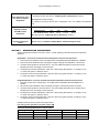
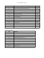
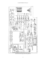
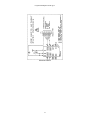
Programmable/Digital Controller pg 1 SERVICE MANUAL FOR DIGITAL AND PROGRAMMABLE MODELS Information is reserved for trained, qualified technical personnel. It includes schematics & wiring diagrams. Any repair or service to a unit is to be performed by a certified technician ONLY. Attempting repairs outlined in this guide may result in voiding your warranty Unplug The Unit Before Servicing 1 2 3 4 5 6 7 8 9 0 +/- FLUID=65.00 C SET =65.00 C FLUID=65.00 C SET =65.00 C FCN SET ON OFF SET ON OFF Programmable Models: Digital Models: 7310, 8010, 9010, 9110, 9510, 9610, 9710 8001, 9001, 9101, 9501, 9601, 9701 TABLE OF CONTENTS Section 1. Section 2. Section 3. Section 4. Section 5. Section 6. Troubleshooting Procedure Refrigeration Temperature & Pressures Replace the Main Control Board Digital/Programmable Field Temperature Calibrations Instructions Spare Parts List Schematics & Wiring Diagram 1 Programmable/Digital Controller pg 2 SECTION 1. TROUBLESHOOTING PROCEDURE Note: If the unit seems to function normally but fails to control or hold temperature steady, first perform instructions as in "Conditions and Steps before Troubleshooting the Unit" Conditions and Steps before Troubleshooting the Unit 1. a. On units that have a HI/LO pump speed switch on the rear panel, set the pump speed to high and connect the Inlet/Outlet connections with a few feet long length of 1/4" diameter (or greater) hose. b. On units without the rear HI/LO speed switch, plug the Inlet/Outlet pipes with Nylon 1/4" NPT plugs. If there is a pump speed selection menu, set the pump speed to setting number 1 (highest setting). 2. Use the same fluid and the same setpoint temperature as used in the application. 3. Unit should visibly pump the fluid inside the reservoir. If not, check that the pump shaft spins freely and impeller(s) are in place. If bearings are worn out, replace the entire pump motor. 4. Check that the fluid or fluid mixture is : a. Watery, not thick like maple syrup. Viscosity <25 centistokes. b. Not boiling on the surface or freezing to the bottom of the reservoir or cooling coils and not within 5°C of the freezing or boiling point of the liquid. 5. If the Inlet/Outlet connections were used for an external application and the unit operates properly, try the following: a. Check that externally applied heat does not exceed the rated cooling power of the refrigeration or external heat loss does not exceed the 1000 watts of the heater. Fluids within 40°C of their boiling point can cause so much heat loss as to require more than the 1000 watts of heat provided by the unit, especially in containers with a large open surface area. b. Cover/uncover and add/remove insulation of both the internal reservoir and external application and tubing. Insulate the top of the fluid with floating plastic or Teflon balls 6. To return to the factory default setting: You may easily reset all parameters to factory default settings. With the unit in 'STANDBY" mode, press the UP ARROW key, then the DOWN ARROW key, then the ON key, then select default EEPROM. PROBLEM #1 Display does not light up, unit shows no activity CORRECTIVE ACTION (a) Check that CONN5 AND CONN6 ribbon connectors are on properly (b) Check F1 and for line voltage from HOT to NEUTRAL. (c) Check all supply voltages: +9V,+5V,-9V and -5V. (d) See section : "Replacing main control board", section 3. 2 Programmable/Digital Controller pg 3 #2 Breaker trips and unit has an RS232 Port. (a) Connect RS-232 port to a computer. The faulty section will be listed (Ignore RTC message) in the first lines of text when turning unit on (b) Check that display board is properly plugged in. (c) Check if U17 on Main Control Board is missing. (d) See "Replacing main control board", section 3. (e) As a last solution, remove trip coil connections from CB1. If the unit still trips, then check for overcurrent. If not, then check if Q4 is shorted. #3 (a) Check that display board is properly plugged in. Breaker trips and unit has no RS232 port. (b) Check if U17 on Main Control Board is missing. (c) See section : "Replacing main control board", section 3. (d) As a last solution, remove trip coil connections from CB1. If the unit still trips, then check for overcurrent. If not, then check if Q4 is shorted. #4 Continuously heats with heat light off or Breaker trips and "TRIAC FAILURE PRESS ON SWITCH" message appears #5 Intermittent heat with heat light on or Unit not heating and heat light is off #6 Unit not pumping #7 Temperature won't reach setpoint temperature. (a) Triac Q5 or ISO2 may be shorted. Lift R61 to check. If heat stays on, Triac is shorted. If heat shuts off, pins 4 and 6 of ISO2 should be shorted. (b) Check that Triac Q5 is properly heat-sinked, with heat sink thermal compound grease and screws tightened. (a) Unplug the unit. Check heater resistance for 14.4 ohms for 120V unit or 58 ohms for 240V. (b) Check continuity of heater wires. (c) Check/replace Triac Q5 and then Triac driver ISO2. See Spare Parts, section 5. Check that setpoint is higher than the actual bath temperature. See "Replacing main control board", section 3. Unit should visibly pump the fluid inside the reservoir. If not, check that the pump shaft spins freely and impeller(s) are in place. If bearings are worn out, replace the entire pump motor. See Spare Parts List, section 5. (a) Check heater resistance as in "No heat" #5. (b) Check that there is line voltage at heater. (c) Check for DC on heater. If more than 30 DC volts, replace Triac. #8 Unit's temperature rises above setpoint temperature and heat light is on/off. The unit's stirring & pumping motion generates heat. Check unit's specification for ambient temperature and conditions. Try uncovering the bath(s), removing insulation, adding a tap water cooling coil or a refrigeration unit. 3 Programmable/Digital Controller pg 4 #9 Unit's temperature won't cool down to setpoint temperature. (a) If below 0°C, try lowering the setpoint a few degrees lower than the desired temperature. If it still does not work, see section : "Replacing main control board", section 3. (b) Refrigeration needs servicing. (c) Check for ice build up around tank or refrigeration coils. Use suitable low temperature fluid. (a) Check that the RTD probe is within ±0.3 ohms of the following table. #10 Readout not within ±0.25°°C of actual temperature. TEMPERATURE: 0°C PR1 SENSOR OHMS: 100.00 20°C 107.79 40°C 115.54 60°C 123.24 (b) If okay, then see: "Replacing main control board", section 3. #11 (a) See #6 "Unit not Pumping" Unstable temperature control. SECTION 2. (b) Refer back to "Conditions & Steps Before Troubleshooting The Unit". REFRIGERATION TEMPERATURES Ambient temperature should be near 25°C. Unit is in normal operating mode with fluid and set temperature displayed. Digital XX01 - To access the head and suction temperatures from the microprocessor: 1. Press and hold the Set/Enter button until display reads "CONTRAST ADJUST PRESS UP or DOWN". 2. Press and hold the Set/Enter button until display changes to display the temperature of the sensors. 3. The lower left temperature is the Head Sensor. The lower middle temperature is the Suction sensor. Disregard the ohms and voltage to avoid confusion. 4. The Head sensor should read between +20°C and +100°C varying with operation. A reading of -51°C or +150°C and higher is a defective sensor. 5. The Suction sensor should read between +20°C and -20°C varying with operation. A reading of -51°C or +150°C and higher is a defective sensor. Programmable XX10 - To access the head and suction temperatures from the microprocessor: 1. Press the Function and Contrast buttons. The display reads "CONTRAST ADJUST PRESS UP or DOWN". 2. Re press and HOLD Set/Enter button until display changes to read the temperature of sensors. 3. The lower left temperature is the Head Senson. The lower middle temperature is the Suction sensor. Disregard the ohms and voltage to avoid confusion. 4. The Head sensor should read between +20°C and +100°C varying with operation. A reading of -51°C or +150°C and higher is a defective sensor. 5. The Suction sensor should read between +20°C and -20°C varying with operation. A reading of -51°C or +150°C and higher is a defective sensor. Example head and suction pressures and temperatures. Full cooling power operation when fluid is above 0°°C Set the set point temperature down to -10°C or below Refrigerant Head PSI Head Temp. Suction PSI Suction Temp. Freon R12 175 100°C 20 > 0°C SUVA MP39 190 100°C 18 > 0°C SUVA R134A 193 100°C 18 > 0°C 4 Programmable/Digital Controller pg 5 When controlling at a stabilized setpoint temperature above 0°°C Refrigerant Head PSI Head Temp. Suction PSI Suction Temp. 15°C to 35°C Freon R12 90 to 110 40°C to 60°C -20 to -10 SUVA MP39 92 to 112 40°C to 60°C -20 to -10 15°C to 35°C SUVA R134A 92 to 112 40°C to 60°C -20 to -10 15°C to 35°C When fluid temperature is below 0°°C Refrigerant Head PSI Head Temp. Suction PSI Suction Temp. Freon R12 95 to 115 40°C to 60°C < -10 -15°C to -10°C SUVA MP39 97 to 117 40°C to 60°C < -10 -15°C to -10°C SUVA R134A 97 to 117 40°C to 60°C < -10 -15°C to -10°C Note: It is normal to hear a quiet click once every five seconds while the compressor runs. This is the modulating valve turning on & off. Quick Valve Seat Check With a refrigeration pressure gauge attached to the suction line an easy check can be done to check the modulation valve and compressor valve seats for a good seal. 1. The two black wires to the modulating valve go to CONN145. Remove this connector from the moducating PC board. 2. Run the refrigeration for about 30 seconds. The suction should drop below -20PSI. 3. Shut off the unit. The pressure should not change for at least a minute. 4. Replace CONN14 when finished. SECTION 3. REPLACING MAIN CONTROL BOARD. When removing/replacing the main control board, always remove/replace the bath temperature probe(s) included with the board. Temperature probes are calibrated to each board at the factory. Do not lose the nylon washer between the board mounting bracket and the main board where the nut fastens. This prevents a possible short circuit to the power supply board. SECTION 4. DIGITAL/PROGRAMMABLE FIELD TEMPERATURE CALIBRATIONS INSTRUCTIONS We recommend sending the Main Control Board, Internal Temperature Probe and External Temperature Probe (if supplied) back to the factory. You will require the following items 1. Computer with RS232 interface, RS232 serial cable. 2. A communications program. We recommend the use of Procomm. 3. Run communications software at: 9600 baud, 1 Start Bit, 8 Data Bits, 1 Stop Bit and No Parity Bit. 4. Two baths, one at zero Celsius (0°C) and one at a high temperature (100°C-200°C) or at the user's most commonly used temperature. You must calibrate both calibration points together. HIGH and LOW calibration points cannot be entered separately. 5. NIST traceable standard thermometer(s). Ranging from 0°C to a temperature between 100°C - 200°C. For units without RS 232 interface socket Refer to schematic RS232 on page 14 for installation. 5 Programmable/Digital Controller pg 6 For units with RS 232 socket If you are calibrating the internal probe, remove the probe from the bath and make sure that it will reach both calibration baths. Run a serial communications program as described above. The commands used below are in between quotation marks and must be in upper case letters. 1. a.UNITS WITH FULL NUMERIC KEYPAD (Programmable models, xx10): Remove refrigeration and heating power connections if desired. Turn on unit and press FCN 8 on keypad. Type "A1<return>" to see echoed characters from the keyboard. Type "$C<return>" and a menu will appear on the computer screen. b.UNITS WITH SIMPLE KEYPAD (Digital models, xx01): While turning on, Hold ON Button Down until "SERIAL LINK COMMUNICATION" appears on the display and a menu appears on the computer screen. Select "A" from the menu and another menu will appear. 2. Type "C" for internal probe. 3. Place probe into the bath near zero Celsius (0°C) and type "L". Let probe settle to temperature and then type in the exact temperature and "<return>". 4. Place probe into a bath at a high temperature, 100°C to 200°C and type "H". Let probe settle to temperature and then type in the exact temperature and "<return>". 5. Type "C". Numbers displayed should now be correct. Place probe back in the low temperature bath to double check the reading. 6. When correct, type "X". The unit will tell you to wait while it stores the new calibration points. ON MODELS WITH EXTERNAL PROBE If the model has an external probe and is in need of calibration, repeat steps 2 through 6 and substitute "D" for "C" in Step 2. If you enter the calibration menu and you are not ready to calibrate the unit, just type "X". The unit will print the wait message just as in Step 6, but only store the current values. SECTION 5. SPARE PARTS LIST REF# DESCRIPTION PART# CAP1 CAPACITOR, MOTOR RUN, 370VAC, 6uF, 120V 205-056 CAP1 CAPACITOR, MOTOR RUN, 440VAC, 3uF, 208-240V 205-060 CB1 TRIP CIRCUIT BREAKER WITH TRIP COIL, 12 AMP, 120V 215-039 CB1 TRIP CIRCUIT BREAKER WITH TRIP COIL, 6 AMP, 240V 215-040 DISPLAY BOARD, TESTED 500-076 H1 HEATER, TUBULAR 5" DIA. COIL, 1KW, 120V 215-119 H1 HEATER, TUBULAR 5" DIA. COIL, 1KW, 240V 215-120 J1 LINE CORD, 120V, 6 FT, 16GA, WITH PLUG FOR USA/CANADA 225-010 J1 LINE CORD, 120V, 8 FT, 14GA, WITH PLUG FOR USA/CANADA 225-159 J1 LINE CORD, 240V, WITH PLUG FOR EUROPE 225-112 J1 LINE CORD, 240V, WITH PLUG FOR AUSTRALIA 225-115 J1 LINE CORD, 240V, WITH PLUG FOR GREAT BRITAIN (UK) 225-116 DSP1 6 Programmable/Digital Controller pg 7 PR1 PROBE, RTD, 100 OHMS @ 0C, 4-WIRE 200-136 S1 SWITCH, PUMP SPEED 235-008 S2 SAFETY THERMOSTAT, OTP 215-122 PCB1 PC BOARD, POWER, 120V, TESTED 500-077 PCB1 PC BOARD, POWER, 240V, TESTED 500-085 MTR1 PUMP MOTOR, FOR MODELS XX01, 120V 215-235 MTR1 PUMP MOTOR, FOR MODELS XX01, 240V 215-236 PCB2 PC BOARD, MAIN CONTROL, CALIBRATED MODELS XX01 500-075 PCB2 PC BOARD, MAIN CONTROL, CALIBRATED MODELS XX10 500-079 MTR2 PUMP MOTOR, FOR MODELS XX10 and 9501,9601 120V 215-113 MTR2 PUMP MOTOR, FOR MODELS XX10 and 9501,9601 240V 215-114 - DECKLID ASSEMBLY 510-035 - COMPLETE REFRIGERATION ASSY, TESTED 120V (2)* 575-050 - COMPLETE REFRIGERATION ASSY, TESTED 240V (2)* 575-051 MOTOR MOUNTING KIT(ORDER WHEN REPLACING MOTOR) FOR MODELS 8001, 9001, 9101 510-020 - COMPRESSOR 1/6 HP, USA MODELS BEFORE SN/926062, 240V, 50HZ (2) (3)* 750-017 - COMPRESSOR 1/4 HP, EUR MODELS AFTER SN/926061, 240V, 50HZ (2) (3)* 750-022 - COMPRESSOR FAN AXIAL 4" 120V (2) (3)* 215-196 - COMPRESSOR FAN AXIAL 4" 240V (2) (3)* 215-197 - COMPLETE REFRIGERATION ASSY, TESTED 120V (3)* 575-142 - COMPLETE REFRIGERATION ASSY, TESTED 240V (3)* 575-143 - COMPLETE REFRIGERATION ASSY, TESTED 120V (4)* 575-054 - COMPLETE REFRIGERATION ASSY, TESTED 240V (4)* 575-055 - DECKLID ASSEMBLY - COMPRESSOR FAN AXIAL 10" 120V (4) (5)* 750-006 - COMPRESSOR FAN AXIAL 10" 240V (4) (5)* 750-021 L1 * (1) (2) (3)* MODULATING VALVE 510-004 (4)* 750-093 (4) (5)* - COMPRESSOR 1/3 HP, USA, 120V, 60HZ (4) (5)* 750-109 - COMPRESSOR 1/2 HP, EUR, 240V, 50HZ (4) (5)* 750-023 PCB4 PC BOARD, MODULATING VALVE COMPRESSOR, 120V (4) (5)* 500-078 PCB4 PC BOARD, MODULATING VALVE COMPRESSOR, 240V (4) (5)* 500-086 - COMPLETE REFRIGERATION ASSY, TESTED 120V (5)* 575-056 - COMPLETE REFRIGERATION ASSY, TESTED 240V (5)* 575-057 - DECKLID ASSEMBLY - TEMP. ADJUST KNOB (1) FOR MODELS 8001, 8010 ONLY (2) FOR MODELS 9001, 9010 ONLY 510-054 (5)* 330-039 (3) FOR MODELS 9101, 9110 ONLY (4) FOR MODELS 9501, 9510 ONLY (5) FOR MODELS 9601, 9610 ONLY 7 XX01: Digital Controller Models XX10: Programmable Controller Models Programmable/Digital Controller pg 8 PC BOARD COMPONENTS REF# DESCRIPTION PART# T1 XFORMER,120/240V, POWER SUPPLY 215-115 T2 XFORMER, 120/240V, MODULATING BOARD 215-116 OPTOISOLATOR/TRIAC DRIVER 200-089 OPTOISOLATOR/CURRENT SENSOR 200-110 Q4 ALTERNISTOR, Q401E3 200-076 Q5,Q6,Q7 ALTERNISTOR, Q4015L9 200-109 ISO1/3/6 ISO4/5 MAIN CONTROL BOARD 500-075 OR 500-079 REF# C1/17/43/46 C2/3/5/6/7/8/16/18/19/27/29/3 2/33/36/37/38/39/41/42/44/51 DESCRIPTION CAPACITOR, TANT, 10uF, 10V PART# - CAPACITOR, CERAMIC MONOLITHIC, 0.1uF, 50V - CAPACITOR, TANT, 1uF, 35V - CAPACITOR, CERAMIC MONOLITHIC, 18pF, 100V - CAPACITOR, LYTIC, 330uF, 16V - C28, C45 CAPACITOR, CERAMIC MONOLITHIC, 0.33uF, 50V - C34, C40 CAPACITOR, TANT, 4.7uF, 10V - CAPACITOR, CERAMIC MONOLITHIC, 0.047uF - RES, 100K, 5%, 1/4W - R4 RES, 2K, 1%, 1/4W - R5 RES, 499 OHMS, 1%, 1/4W - R6 RES, 475, 1%, 1/4W - R7 RES, 80.6K, 1%, 1/4W - R8,R17 RES, 10K, 1%, 1/4W - R28 RES, 10K, 5%, 1/4W - R30/31/32,33/45/46/47/49 RES, 100K, 0.5%, 1/4W - R18 RES, 51.1K, 1%, 1/4W - R20,R21 RES, 2.7K, 5%, 1/4W - RES, ZERO OHM - R34,R48 RES, 500 OHM, 0.1%, 1/4W - R35,R43 RES, 10K,1%, 1/4W - R36,R44 RES, 1.3K,1%, 1/4W - R37,R42 RES, 4.7K,1%, 1/4W - R38 RES, 200 OHM, 1%, 1/4W - R39,R41,R53 RES, 10 OHM, 1%, 1/4W - RES, 4.7K, 5%, 1/4W - RES, 1K, 5%, 1/4W - TRANSISTOR, PNP 2N3906 - C9,10,11,12 C14, C15 C26 C35 R1,R78,R79 R29 R40 R84,R85 Q8 8 Programmable/Digital Controller pg 9 SPEAK1 SPEAKER, PIEZOELECTRIC, MINIATURE 200-114 U1 IC, MICROPROCESSOR HD63A03XP 200-115 U2 IC, EPROM, (GIVE VERSION CODE WRITTEN ON CHIP) 200-116 U3 IC, RAM,STATIC 43256 200-117 U4 IC, TRANSCEIVER 74HC245N 200-118 U5 IC,PEEL 18CV8-35 200-119 U7 IC,+5V VOLTAGE REGULATOR LM2940CT 200-120 U8 IC,DRIVER ARRAY ULN2003L 200-121 U9 IC,RS232 DRIVER MAX233CPA 200-122 U10 IC,WATCHDOG MAX690 200-123 U12 IC,QUAD ANALOG SWITCH DG211 200-133 IC,OP AMP,DUAL AD706JN 200-125 U14 IC,A/D-D/A CONVERTER PCF8591PN 200-127 U15 IC,VOLTAGE REFERENCE,2.5V LM336Z-2.5 200-128 U17 IC,EEPROM X24C02P 200-129 U18 IC,D-FLIP-FLOP,OCTAL,3-STATE 74HC574 200-130 U20 IC,A/D CONVERTER,16 BIT C5501 200-131 U22 IC,VOLTAGE REGULATOR,-5V,79L05A OR LM320LZ-5 200-132 Y1 CRYSTAL,4.915 MHZ 200-113 U13,U19,U21 DISPLAY BOARD 500-076 REF# C13,C31 D1 D2,D3 DESCRIPTION CAPACITOR, CERAMIC MONOLITHIC, 0.1uF,50V LED,SQUARE,GREEN LED,SQUARE,RED Q1 TRANSISTOR,NPN 2N3904 Q2 TRANSISTOR,NPN,DARLINGTON TIP 110 R13,R14,R15 RES, 150 OHMS, 5%, 1/4W R51,R52,R81 RES, 10K, 1%, 1/4W R54 RES, 9.09K, 1%, 1/4W R55 RES, 1K, 5%, 1/4W R57 RES, 2.21 OHMS, 1%, 1/4W R58 RES, 4.7K, 5%, 1/4W R80 RES, 47K, 5%, 1/4W R82 RES, 10K, 1%, 1/4W 9 Programmable/Digital Controller pg 10 POWER SUPPLY 500-077 OR 500-085 REF# DESCRIPTION BR1,2 BRIDGE, RECTIFIER, 1.5A C1 CAPACITOR, LYTIC, 1000 MFD, 50V C47 CAPACITOR, LYTIC, 2200 MFD, 16V C48 CAPACITOR, LYTIC, 330 MFD, 16V C50 CAPACITOR, LYTIC, 0.1 MFD, 400V (0.47uF FOR 240V) D1,D6 DIODE, 1N4005 F1 FUSE, 2AG, 250V, 1/4(.25) AMPERE Q3 TRANSISTOR, HEXFET, IRFZ 12-ND R1,R11,R12 R59,R61,R63,R75 R60,R62,R64,R76 R65,R70 RESISTOR, 100K, 1/4W, 5% RESISTOR, 51 OHM, 1/4W,5% RESISTOR, 270 OHM, 1/4W,1% RESISTOR, 10K, 1/4W, 5% R66,R67,R68,R69, R71,R72,R73,R74 RESISTOR, 33.2K, 1/4W, 1%, 120V R66,R67,R68,R69, R71,R72,R73,R74 RESISTOR, 100K, 1/4W, 5%, 240V R83 RESISTOR, 100 OHMS, 1/4W, 5% 10 Programmable/Digital Controller pg 11 SECTION 6. SCHEMATICS & WIRING DIAGRAM Schematic DTC Display Board 11 Programmable/Digital Controller pg 12 Schematic Main Control Board 12 Programmable/Digital Controller pg 13 Schematic Power Supply and Wiring Diagram 13 Programmable/Digital Controller pg 14 Schematic RS232 14