1
UCS 1000
R4.2
Administration
585-313-507
Comcode 108725904
April 2000
Issue 3
Copyright © 2000 by Lucent Technologies. All rights reserved.
For trademark, regulatory compliance, and related legal information, see the
copyright and legal notices section of this document.
Copyright and legal notices
Copyright
Copyright © 2000 by Lucent Technologies.
All rights reserved.
Printed in the USA.
This material is protected by the copyright laws of the United States and other
countries. It may not be reproduced, distributed, or altered in any fashion by
any entity (either internal or external to Lucent Technologies), except in
accordance with applicable agreements, contracts or licensing, without the
express written consent of the Enterprise Networks (EN) Global Learning
Solutions (GLS) organization and the business management owner of the
material.
Acknowledgment
This document was prepared by the GLS organization of the EN division of
Lucent Technologies. Offices are located in Denver CO, Columbus OH,
Middletown NJ, and Basking Ridge NJ, USA.
UCS 1000 R4.2 Administration 585-313-507
Issue 3 April 2000 iii
Copyright and legal notices
Trademarks
Lucent Technologies has made every effort to supply the following trademark
information about company names, products, and services mentioned in the
UCS 1000 R4.2 documentation library:
•
Adobe Systems, Inc. — Trademarks: Adobe, Acrobat.
•
Enhanced Software Technologies, Inc. — Trademark: Quickstart.
•
Equinox Systems, Inc. — Registered trademark: Equinox
•
Hewlett Packard Corporation — Registered trademarks: Hewlett-Packard
and HP
•
Intel Corporation — Registered trademarks: Pentium.
•
International Business Machines Corporation — Registered trademarks:
IBM, VTAM.
•
Lucent Technologies — Registered trademarks: 4ESS, 5ESS, AUDIX,
CONVERSANT, DEFINITY, Voice Power. Trademarks: FlexWord, Intuity,
Lucent.
•
Microsoft Corporation — Registered trademarks: Excel, Internet Explorer,
Microsoft, MS, MS-DOS, Windows, Windows NT.
•
Mylex Corporation — Registered trademark: Mylex.
•
Novell, Inc. — Registered trademarks: Novell.
UCS 1000 R4.2 Administration 585-313-507
Issue 3 April 2000 iv
Copyright and legal notices
Limited Warranty
•
Oracle Corporation — Trademarks: OBJECT*SQL, ORACLE,
ORACLE*Terminal, PRO*C, SQL*FORMS, SQL*Menu, SQL*Net,
SQL*Plus, SQL*ReportWriter.
•
PCI Industrial Computer Manufacturers Group — Registered trademarks:
CompactPCI and PICMG.
•
Santa Cruz Operation, Inc. — Registered trademarks: UnixWare.
•
Sun Microsystems — Registered trademarks: Sun, Sun Microsystems,
Sun Workstation, Solaris (computer and peripherals). Trademarks:
Solaris (operating system utilities) and Java
•
UNIX System Laboratories, Inc. — Registered trademarks: UNIX.
•
Xerox Corporation — Trademarks: Ethernet.
Lucent Technologies provides a limited warranty on this product. Refer to the
“Limited Use Software License Agreement” card provided with your package.
Lucent Technologies has determined that use of this electronic data delivery
system cannot cause harm to an end user's computing system and will not
assume any responsibility for problems that may arise with a user's computer
system while accessing the data in these documents.
Every effort has been made to make sure that this document is complete and
accurate at the time of release, but information is subject to change.
UCS 1000 R4.2 Administration 585-313-507
Issue 3 April 2000 v
Copyright and legal notices
United States FCC
Compliance
Information
Part 15: Class A statement. This equipment has been tested and found to
comply with the limits for a Class A digital device, pursuant to Part 15 of the
FCC Rules. These limits are designed to provide reasonable protection
against harmful interference when the equipment is operated in a commercial
environment. This equipment generates, uses, and can radiate radiofrequency energy and, if not installed and used in accordance with the
instructions, may cause harmful interference to radio communications.
Operation of this equipment in a residential area is likely to cause harmful
interference, in which case the user will be required to correct the
interference at his own expense.
Canadian
Department of
Communications
(DOC) Interference
Information
This digital apparatus does not exceed the Class A limits for radio noise
emissions set out in the radio interference regulations of the Canadian
Department of Communications.
Toll Fraud
Le Présent Appareil Nomérique n’émet pas de bruits radioélectriques
dépassant les limites applicables aux appareils numériques de la class A
préscrites dans le reglement sur le brouillage radioélectrique édicté par le
ministére des Communications du Canada.
Toll fraud is the unauthorized use of your telecommunications system by an
unauthorized party, for example, persons other than your company’s
employees, agents, subcontractors, or persons working on your company’s
behalf. Note that there may be a risk of toll fraud associated with your
telecommunications system and, if toll fraud occurs, it can result in
substantial additional charges for your telecommunications services.
UCS 1000 R4.2 Administration 585-313-507
Issue 3 April 2000 vi
Copyright and legal notices
Your Responsibility for Your System’s Security
You and your system manager are responsible for the security of your system
and for preventing unauthorized use. You are also responsible for reading all
installation, instruction, and system administration documents provided with
this product in order to fully understand the features that can introduce risk of
toll fraud and the steps that can be taken to reduce that risk. Lucent
Technologies does not warrant that this product is immune from or will
prevent unauthorized use of common-carrier telecommunication services or
facilities accessed through or connected to it. Lucent Technologies will not be
responsible for any charges that result from such unauthorized use.
Lucent Technologies Fraud Intervention and Corporate Security
If you suspect that you are being victimized by toll fraud and you need
technical support or assistance, call the Lucent Technologies National
Customer Care Center Toll Fraud Intervention Hotline at 1 800 643-2353.
Aside from whether immediate support is required, all toll fraud incidents
involving Lucent products or services should be reported to Lucent Corporate
Security at 1 800 821-8235. In addition to recording the incident, Lucent
Corporate Security is available for consultation on security issues,
investigation support, referral to law enforcement agencies, and educational
programs.
UCS 1000 R4.2 Administration 585-313-507
Issue 3 April 2000 vii
Copyright and legal notices
Documentation
Ordering
Information
Call or Write
Lucent Technologies Publications Center
2855 N. Franklin Road
Indianapolis, IN 46219
Voice
FAX
1 800 457-1235
1 800 457-1764
International Voice 317 322-6791
International FAX 317 322-6699
To Order
To order a document, contact the Lucent Technologies Publications Center
and specify the 9-digit document number, the issue number, and the issue
date.
Standing Orders
You can be placed on a standing order list for this and other documents you
may need. Standing order will enable you to automatically receive updated
versions of individual documents or document sets, billed to account
information that you provide. For more information on standing orders, or to
be put on a list to receive future issues of this document, contact the Lucent
Technologies Publications Center (see the contact information above).
UCS 1000 R4.2 Administration 585-313-507
Issue 3 April 2000 viii
Contents
Copyright and legal notices
About This Book
iii
xxii
Overview . . . . . . . . . . . . . . . . . . . . . . . . . . . . . . . . . . . . . . xxii
Intended Audiences . . . . . . . . . . . . . . . . . . . . . . . . . . . . . . . . xxiii
How This Book Is Organized. . . . . . . . . . . . . . . . . . . . . . . . . . . . xxiii
Administration Procedures and Information. . . . . . . . . . . . . . . . . . . . . . . . . . . . xxiv
Reference Material . . . . . . . . . . . . . . . . . . . . . . . . . . . . . . . . . . . . . . . . . . . . . . .xxv
To Locate Specific Topics . . . . . . . . . . . . . . . . . . . . . . . . . . . . . . . . . . . . . . . . . .xxv
Conventions Used in This Book . . . . . . . . . . . . . . . . . . . . . . . . . . xxv
Other Typography . . . . . . . . . . . . . . . . . . . . . . . . . . . . . . . . . . . . . . . . . . . . . . xxxiii
Safety and Security Alert Labels . . . . . . . . . . . . . . . . . . . . . . . . . xxxiv
Related Resources. . . . . . . . . . . . . . . . . . . . . . . . . . . . . . . . . xxxv
Using the CD-ROM Documentation. . . . . . . . . . . . . . . . . . . . . . . . . . . . . . . . . xxxvi
How to Comment on This Book . . . . . . . . . . . . . . . . . . . . . . . . . xxxix
1 Administration Overview
1
Overview . . . . . . . . . . . . . . . . . . . . . . . . . . . . . . . . . . . . . . . 1
UCS 1000 R4.2 Administration 585-313-507
Issue 3 April 2000 ix
User Interface Overview . . . . . . . . . . . . . . . . . . . . . . . . . . . . . . . 1
UCS 1000 R4.2 User Interface . . . . . . . . . . . . . . . . . . . . . . . . . . . 2
Cursor Movement Keys . . . . . . . . . . . . . . . . . . . . . . . . . . . . . . . . . . . . . . . . . . . . . 4
Menus and Windows . . . . . . . . . . . . . . . . . . . . . . . . . . . . . . . . . . . . . . . . . . . . . . . 5
Message Line . . . . . . . . . . . . . . . . . . . . . . . . . . . . . . . . . . . . . . . . . . . . . . . . . . . 10
Function Keys . . . . . . . . . . . . . . . . . . . . . . . . . . . . . . . . . . . . . . . . . . . . . . . . . . . 11
Online Help . . . . . . . . . . . . . . . . . . . . . . . . . . . . . . . . . . . . . 17
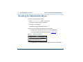
Accessing the Administration Menus . . . . . . . . . . . . . . . . . . . . . . . . 18
Administration Menu Options. . . . . . . . . . . . . . . . . . . . . . . . . . . . . . . . . . . . . . . . 20
2 UNIX Administration
22
Overview . . . . . . . . . . . . . . . . . . . . . . . . . . . . . . . . . . . . . . . 22
UnixWare Documentation . . . . . . . . . . . . . . . . . . . . . . . . . . . . . . 22
UNIX System Administration Access . . . . . . . . . . . . . . . . . . . . . . . . 23
Application Administration . . . . . . . . . . . . . . . . . . . . . . . . . . . . . . 25
Backup Scheduling, Setup and Control . . . . . . . . . . . . . . . . . . . . . . . 25
Basic Backup . . . . . . . . . . . . . . . . . . . . . . . . . . . . . . . . . . . . . . . . . . . . . . . . . . . . 28
Performing Extended Backup Services . . . . . . . . . . . . . . . . . . . . . . . . . . . . . . . . 43
File System Creation, Checking, and Mounting . . . . . . . . . . . . . . . . . . . 43
Machine Configuration, Display, and Shutdown . . . . . . . . . . . . . . . . . . . 44
Memory Size Disparity. . . . . . . . . . . . . . . . . . . . . . . . . . . . . . . . . . . . . . . . . . . . . 45
Network Services Administration . . . . . . . . . . . . . . . . . . . . . . . . . . 46
UCS 1000 R4.2 Administration 585-313-507
Issue 3 April 2000 x
Port Access Services and Monitors . . . . . . . . . . . . . . . . . . . . . . . . . 47
Printer Configuration and Services . . . . . . . . . . . . . . . . . . . . . . . . . 47
Restore from Backup Data. . . . . . . . . . . . . . . . . . . . . . . . . . . . . . 48
Basic Restore Services . . . . . . . . . . . . . . . . . . . . . . . . . . . . . . . . . . . . . . . . . . . . 48
Extended Restore Services . . . . . . . . . . . . . . . . . . . . . . . . . . . . . . . . . . . . . . . . . 49
Schedule Automatic Task . . . . . . . . . . . . . . . . . . . . . . . . . . . . . . 50
Security Management . . . . . . . . . . . . . . . . . . . . . . . . . . . . . . . . 51
Software Installation and Removal. . . . . . . . . . . . . . . . . . . . . . . . . . 52
Storage Device Operations and Definition . . . . . . . . . . . . . . . . . . . . . . 53
System Name, Date and Time, and Initial Password Setup . . . . . . . . . . . . . 54
User Login and Group Administration . . . . . . . . . . . . . . . . . . . . . . . . 56
Exit UNIX System Administration Menu . . . . . . . . . . . . . . . . . . . . . . . 57
3 Voice System Administration
58
Overview . . . . . . . . . . . . . . . . . . . . . . . . . . . . . . . . . . . . . . . 58
Accessing the Voice System Administration Menu . . . . . . . . . . . . . . . . . . . . . . . 58
Voice System Administration Menu Options . . . . . . . . . . . . . . . . . . . . . . . . . . . . 59
Configuration Management . . . . . . . . . . . . . . . . . . . . . . . . . . . . . 62
Feature Licensing . . . . . . . . . . . . . . . . . . . . . . . . . . . . . . . . . . 64
Printing a Feature License Report . . . . . . . . . . . . . . . . . . . . . . . . . . . . . . . . . . . . 66
Message Administration . . . . . . . . . . . . . . . . . . . . . . . . . . . . . . . 67
Accessing Message Administration . . . . . . . . . . . . . . . . . . . . . . . . . . . . . . . . . . . 68
UCS 1000 R4.2 Administration 585-313-507
Issue 3 April 2000 xi
Adding Message Destinations . . . . . . . . . . . . . . . . . . . . . . . . . . . . . . . . . . . . . . . 72
Removing Message Destinations . . . . . . . . . . . . . . . . . . . . . . . . . . . . . . . . . . . . 74
Adding Thresholds. . . . . . . . . . . . . . . . . . . . . . . . . . . . . . . . . . . . . . . . . . . . . . . . 76
Removing Thresholds . . . . . . . . . . . . . . . . . . . . . . . . . . . . . . . . . . . . . . . . . . . . . 78
Modifying Message Priorities. . . . . . . . . . . . . . . . . . . . . . . . . . . . . . . . . . . . . . . . 79
Modifying Threshold Periods . . . . . . . . . . . . . . . . . . . . . . . . . . . . . . . . . . . . . . . . 81
Saving Changes and Exiting Message Administration . . . . . . . . . . . . . . . . . . . . 83
System Control . . . . . . . . . . . . . . . . . . . . . . . . . . . . . . . . . . . 84
Diagnose . . . . . . . . . . . . . . . . . . . . . . . . . . . . . . . . . . . . . . . . . . . . . . . . . . . . . . . 85
Renumbering Voice Channels . . . . . . . . . . . . . . . . . . . . . . . . . . . . . . . . . . . . . . . 87
Reporting Voice System Status . . . . . . . . . . . . . . . . . . . . . . . . . . . . . . . . . . . . . . 89
Stopping the Voice System . . . . . . . . . . . . . . . . . . . . . . . . . . . . . . . . . . . . . . . . . 90
Shutting Down the System . . . . . . . . . . . . . . . . . . . . . . . . . . . . . . . . . . . . . . . . . 91
Starting the Voice System . . . . . . . . . . . . . . . . . . . . . . . . . . . . . . . . . . . . . . . . . . 93
Voice Equipment . . . . . . . . . . . . . . . . . . . . . . . . . . . . . . . . . . . 94
Display the Voice Equipment Window . . . . . . . . . . . . . . . . . . . . . . . . . . . . . . . . . 95
Equipment Options . . . . . . . . . . . . . . . . . . . . . . . . . . . . . . . . . . . . . . . . . . . . . . 101
Equipment State . . . . . . . . . . . . . . . . . . . . . . . . . . . . . . . . . . . . . . . . . . . . . . . . 103
Groups to Channels. . . . . . . . . . . . . . . . . . . . . . . . . . . . . . . . . . . . . . . . . . . . . . 109
LSPS Functions . . . . . . . . . . . . . . . . . . . . . . . . . . . . . . . . . . . . . . . . . . . . . . . . . 113
SSP Functions . . . . . . . . . . . . . . . . . . . . . . . . . . . . . . . . . . . . . . . . . . . . . . . . . . 118
Voice Services . . . . . . . . . . . . . . . . . . . . . . . . . . . . . . . . . . . . . . . . . . . . . . . . . . 122
Printing a Voice Equipment Report . . . . . . . . . . . . . . . . . . . . . . . . . . . . . . . . . . 137
FAX Administration. . . . . . . . . . . . . . . . . . . . . . . . . . . . . . . . . 138
UCS 1000 R4.2 Administration 585-313-507
Issue 3 April 2000 xii
4 Switch Interface Administration
141
Overview . . . . . . . . . . . . . . . . . . . . . . . . . . . . . . . . . . . . . .
Switch Interfaces Hardware . . . . . . . . . . . . . . . . . . . . . . . . . . . .
Accessing the Switch Interfaces Menu . . . . . . . . . . . . . . . . . . . . . .
Digital Interfaces . . . . . . . . . . . . . . . . . . . . . . . . . . . . . . . . . .
Accessing the Digital Interfaces Menu. . . . . . . . . . . . . . . . . . . . . . . . . . . . . . . .
Displaying Digital Interface Assignments. . . . . . . . . . . . . . . . . . . . . . . . . . . . . .
T1 A/B Robbed-bit E&M Protocol . . . . . . . . . . . . . . . . . . . . . . . . . . . . . . . . . . .
E1 CAS Protocols . . . . . . . . . . . . . . . . . . . . . . . . . . . . . . . . . . . . . . . . . . . . . . .
ISDN-PRI Layer 1 Protocol . . . . . . . . . . . . . . . . . . . . . . . . . . . . . . . . . . . . . . . .
T1 for 4ESS Applications. . . . . . . . . . . . . . . . . . . . . . . . . . . . . . . . . . . . . . . . . .
Changing Switch System Parameters . . . . . . . . . . . . . . . . . . . . . . .
Displaying Switch System Parameters . . . . . . . . . . . . . . . . . . . . . .
5 Database Administration
196
Overview . . . . . . . . . . . . . . . . . . . . . . . . . . . . . . . . . . . . . .
Databases and the Voice System . . . . . . . . . . . . . . . . . . . . . . . . .
Call Data Tables . . . . . . . . . . . . . . . . . . . . . . . . . . . . . . . . . .
CCA Table . . . . . . . . . . . . . . . . . . . . . . . . . . . . . . . . . . . . . . . . . . . . . . . . . . . . .
CCASUM Table . . . . . . . . . . . . . . . . . . . . . . . . . . . . . . . . . . . . . . . . . . . . . . . . .
CALL Table . . . . . . . . . . . . . . . . . . . . . . . . . . . . . . . . . . . . . . . . . . . . . . . . . . . .
SERVICE Table . . . . . . . . . . . . . . . . . . . . . . . . . . . . . . . . . . . . . . . . . . . . . . . . .
CDHSUM Table . . . . . . . . . . . . . . . . . . . . . . . . . . . . . . . . . . . . . . . . . . . . . . . . .
UCS 1000 R4.2 Administration 585-313-507
141
141
142
144
144
146
150
163
174
188
191
194
196
196
197
199
199
200
201
202
Issue 3 April 2000 xiii
EVENTS Table. . . . . . . . . . . . . . . . . . . . . . . . . . . . . . . . . . . . . . . . . . . . . . . . . .
EVSUM Table . . . . . . . . . . . . . . . . . . . . . . . . . . . . . . . . . . . . . . . . . . . . . . . . . .
TRASUM Table . . . . . . . . . . . . . . . . . . . . . . . . . . . . . . . . . . . . . . . . . . . . . . . . .
OLDCDH View. . . . . . . . . . . . . . . . . . . . . . . . . . . . . . . . . . . . . . . . . . . . . . . . . .
Relationship Between the CALL, SERVICE, and EVENT Tables . . . . . . . . . . .
Resizing Call Data Tables . . . . . . . . . . . . . . . . . . . . . . . . . . . . . . . . . . . . . . . . .
Verify Call Data Tables. . . . . . . . . . . . . . . . . . . . . . . . . . . . . . . . . . . . . . . . . . . .
Table Searches . . . . . . . . . . . . . . . . . . . . . . . . . . . . . . . . . . . . . . . . . . . . . . . . .
Database Interface Process . . . . . . . . . . . . . . . . . . . . . . . . . . . .
Database DIP Timeout. . . . . . . . . . . . . . . . . . . . . . . . . . . . . . . . . . . . . . . . . . . .
Database Cursors . . . . . . . . . . . . . . . . . . . . . . . . . . . . . . . . . . . . . . . . . . . . . . .
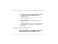
Increasing Database Storage Size. . . . . . . . . . . . . . . . . . . . . . . . .
Decreasing the Database Storage Size . . . . . . . . . . . . . . . . . . . . . .
Reducing the Amount of Call Data Stored. . . . . . . . . . . . . . . . . . . . . . . . . . . . .
Reducing the Number of Days Data is Stored. . . . . . . . . . . . . . . . . . . . . . . . . .
Changing the Data Storage Number of Days . . . . . . . . . . . . . . . . . . . . . . . . . .
Increasing the Shared Pool Size. . . . . . . . . . . . . . . . . . . . . . . . . .
Rollback Segment . . . . . . . . . . . . . . . . . . . . . . . . . . . . . . . . .
Verifying or Reducing the Size of the Rollback Segment . . . . . . . . . . . . . . . . .
Voice System Database Administration . . . . . . . . . . . . . . . . . . . . . .
Database Access ID Table Window. . . . . . . . . . . . . . . . . . . . . . . . . . . . . . . . . .
Adding a Local Database Access ID . . . . . . . . . . . . . . . . . . . . . . . . . . . . . . . . .
Adding a Remote Database Access ID Using SQL*NET V2 . . . . . . . . . . . . . . .
UCS 1000 R4.2 Administration 585-313-507
202
203
204
204
204
206
208
210
213
213
215
217
220
220
220
222
223
224
225
228
230
231
233
Issue 3 April 2000 xiv
Completing ORACLE Environment Setup if
Server is Not a UCS 1000 R4.2 . . . . . . . . . . . . . . . . . . . . . . . . . . . . . . . . . . .
Accessing a Remote Database Using PRO*C or SQL*PLUS . . . . . . . . . . . . . .
Removing a Database Access ID . . . . . . . . . . . . . . . . . . . . . . . . . . . . . . . . . . .
SQL*PLUS Database Administration . . . . . . . . . . . . . . . . . . . . . . .
Monitoring the Database . . . . . . . . . . . . . . . . . . . . . . . . . . . . . .
Database Commands . . . . . . . . . . . . . . . . . . . . . . . . . . . . . . . . . . . . . . . . . . . .
Database Trace Files. . . . . . . . . . . . . . . . . . . . . . . . . . . . . . . . . . . . . . . . . . . . .
6 Peripheral Administration
253
Overview . . . . . . . . . . . . . . . . . . . . . . . . . . . . . . . . . . . . . .
Accessing the Unix Management Menu . . . . . . . . . . . . . . . . . . . . . .
Modem Administration . . . . . . . . . . . . . . . . . . . . . . . . . . . . . . .
Installing the Modem . . . . . . . . . . . . . . . . . . . . . . . . . . . . . . . . . . . . . . . . . . . . .
Configuring the Modem . . . . . . . . . . . . . . . . . . . . . . . . . . . . . . . . . . . . . . . . . . .
Administering the Modem . . . . . . . . . . . . . . . . . . . . . . . . . . . . . . . . . . . . . . . . .
Printer Administration . . . . . . . . . . . . . . . . . . . . . . . . . . . . . . .
Installing the Printer . . . . . . . . . . . . . . . . . . . . . . . . . . . . . . . . . . . . . . . . . . . . . .
Configuring the Printer on the Voice System . . . . . . . . . . . . . . . . . . . . . . . . . . .
Administering the Printer on the Voice System . . . . . . . . . . . . . . . . . . . . . . . . .
Setting Up the Printer . . . . . . . . . . . . . . . . . . . . . . . . . . . . . . . . . . . . . . . . . . . .
Remote Terminal Administration . . . . . . . . . . . . . . . . . . . . . . . . . .
Configuring the Remote Terminal . . . . . . . . . . . . . . . . . . . . . . . . . . . . . . . . . . .
UCS 1000 R4.2 Administration 585-313-507
239
240
245
246
247
247
252
253
253
255
256
256
266
278
278
279
289
291
292
293
Issue 3 April 2000 xv
Administering the Remote Terminal. . . . . . . . . . . . . . . . . . . . . . . . . . . . . . . . . . 295
7 Common Administration
297
Overview . . . . . . . . . . . . . . . . . . . . . . . . . . . . . . . . . . . . . .
Command Menu . . . . . . . . . . . . . . . . . . . . . . . . . . . . . . . . . .
Accessing the Command Menu. . . . . . . . . . . . . . . . . . . . . . . . . . . . . . . . . . . . .
System Monitor . . . . . . . . . . . . . . . . . . . . . . . . . . . . . . . . . . . . . . . . . . . . . . . . .
Trace Service. . . . . . . . . . . . . . . . . . . . . . . . . . . . . . . . . . . . . . . . . . . . . . . . . . .
Reports Administration. . . . . . . . . . . . . . . . . . . . . . . . . . . . . . .
Accessing the Reports Administration Menu . . . . . . . . . . . . . . . . . . . . . . . . . . .
Call Classification Report. . . . . . . . . . . . . . . . . . . . . . . . . . . . . . . . . . . . . . . . . .
Call Data Detail Report . . . . . . . . . . . . . . . . . . . . . . . . . . . . . . . . . . . . . . . . . . .
Call Data Summary Report . . . . . . . . . . . . . . . . . . . . . . . . . . . . . . . . . . . . . . . .
Message Log Report . . . . . . . . . . . . . . . . . . . . . . . . . . . . . . . . . . . . . . . . . . . . .
Administrative Commands Log Report . . . . . . . . . . . . . . . . . . . . . . . . . . . . . . .
Traffic Report . . . . . . . . . . . . . . . . . . . . . . . . . . . . . . . . . . . . . . . . . . . . . . . . . . .
Signal Processing Activity Report . . . . . . . . . . . . . . . . . . . . . . . . . . . . . . . . . . .
Custom Database Reports . . . . . . . . . . . . . . . . . . . . . . . . . . . . . . . . . . . . . . . .
Common Administrative Procedures. . . . . . . . . . . . . . . . . . . . . . . .
A Summary of Commands
297
297
298
298
306
308
309
310
317
325
333
344
352
358
360
361
362
Overview . . . . . . . . . . . . . . . . . . . . . . . . . . . . . . . . . . . . . . 362
add . . . . . . . . . . . . . . . . . . . . . . . . . . . . . . . . . . . . . . . . . 371
UCS 1000 R4.2 Administration 585-313-507
Issue 3 April 2000 xvi
addhdr . . . . . . . .
alarm_cutoff . . . . .
annotate . . . . . . .
assign card/channel .
assign_permissions .
assign service/startup
attach . . . . . . . .
autoreboot . . . . . .
bbs . . . . . . . . . .
ccarpt . . . . . . . .
cddrpt . . . . . . . .
cdsrpt . . . . . . . .
codetype . . . . . . .
configure_tam . . . .
copy . . . . . . . . .
cpuType . . . . . . .
cvis_mainmenu . . .
cvis_menu . . . . . .
dbcheck . . . . . . .
dbfrag . . . . . . . .
dbfree . . . . . . . .
dbused . . . . . . . .
UCS 1000 R4.2 Administration 585-313-507
.
.
.
.
.
.
.
.
.
.
.
.
.
.
.
.
.
.
.
.
.
.
.
.
.
.
.
.
.
.
.
.
.
.
.
.
.
.
.
.
.
.
.
.
.
.
.
.
.
.
.
.
.
.
.
.
.
.
.
.
.
.
.
.
.
.
.
.
.
.
.
.
.
.
.
.
.
.
.
.
.
.
.
.
.
.
.
.
.
.
.
.
.
.
.
.
.
.
.
.
.
.
.
.
.
.
.
.
.
.
.
.
.
.
.
.
.
.
.
.
.
.
.
.
.
.
.
.
.
.
.
.
.
.
.
.
.
.
.
.
.
.
.
.
.
.
.
.
.
.
.
.
.
.
.
.
.
.
.
.
.
.
.
.
.
.
.
.
.
.
.
.
.
.
.
.
.
.
.
.
.
.
.
.
.
.
.
.
.
.
.
.
.
.
.
.
.
.
.
.
.
.
.
.
.
.
.
.
.
.
.
.
.
.
.
.
.
.
.
.
.
.
.
.
.
.
.
.
.
.
.
.
.
.
.
.
.
.
.
.
.
.
.
.
.
.
.
.
.
.
.
.
.
.
.
.
.
.
.
.
.
.
.
.
.
.
.
.
.
.
.
.
.
.
.
.
.
.
.
.
.
.
.
.
.
.
.
.
.
.
.
.
.
.
.
.
.
.
.
.
.
.
.
.
.
.
.
.
.
.
.
.
.
.
.
.
.
.
.
.
.
.
.
.
.
.
.
.
.
.
.
.
.
.
.
.
.
.
.
.
.
.
.
.
.
.
.
.
.
.
.
.
.
.
.
.
.
.
.
.
.
.
.
.
.
.
.
.
.
.
.
.
.
.
.
.
.
.
.
.
.
.
.
.
.
.
.
.
.
.
.
.
.
.
.
.
.
.
.
.
.
.
.
.
.
.
.
.
.
.
.
.
.
.
.
.
.
.
.
.
.
.
.
.
.
.
.
.
.
.
.
.
.
.
.
.
.
.
.
.
.
.
.
.
.
.
.
.
.
.
.
.
.
.
.
.
.
.
.
.
.
.
.
.
.
.
.
.
.
.
.
.
.
.
.
.
.
.
.
.
.
.
.
.
.
.
.
.
.
.
.
.
.
.
.
.
.
.
.
.
.
.
.
.
.
.
.
.
.
.
.
.
.
.
.
.
.
.
.
.
.
.
.
.
.
.
.
.
.
.
.
.
.
.
.
.
.
.
.
.
.
.
.
.
.
.
.
.
.
.
.
.
.
.
.
.
.
.
.
.
.
.
.
.
.
.
.
.
.
.
.
.
.
.
.
.
.
.
.
.
.
.
.
.
.
.
.
.
.
.
.
.
.
.
.
.
.
.
.
.
.
.
.
.
.
.
.
.
.
.
.
.
.
.
.
.
.
.
.
.
.
.
.
.
.
.
.
.
.
.
.
.
.
.
.
.
.
.
.
.
.
.
.
.
.
.
.
.
.
.
.
.
.
.
.
.
.
.
.
.
.
.
.
.
.
.
.
.
.
.
.
.
.
.
.
.
.
.
.
.
.
.
373
374
374
375
377
379
382
384
387
390
391
394
396
397
398
399
400
401
401
406
408
410
Issue 3 April 2000 xvii
decode . . . . . . . .
defService . . . . . .
delete card/channel .
delete eqpgrp . . . .
delete service/startup
detach . . . . . . . .
diagnose bus 1. . . .
diagnose card . . . .
dip_int . . . . . . . .
display assignments .
display card . . . . .
display channel . . .
display dnis . . . . .
display eqpgrp/group.
display equipment . .
display messages . .
display_permissions .
display services . . .
display_tam . . . . .
dspActAlarms . . . .
dspRetAlarms . . . .
edExplain . . . . . .
UCS 1000 R4.2 Administration 585-313-507
.
.
.
.
.
.
.
.
.
.
.
.
.
.
.
.
.
.
.
.
.
.
.
.
.
.
.
.
.
.
.
.
.
.
.
.
.
.
.
.
.
.
.
.
.
.
.
.
.
.
.
.
.
.
.
.
.
.
.
.
.
.
.
.
.
.
.
.
.
.
.
.
.
.
.
.
.
.
.
.
.
.
.
.
.
.
.
.
.
.
.
.
.
.
.
.
.
.
.
.
.
.
.
.
.
.
.
.
.
.
.
.
.
.
.
.
.
.
.
.
.
.
.
.
.
.
.
.
.
.
.
.
.
.
.
.
.
.
.
.
.
.
.
.
.
.
.
.
.
.
.
.
.
.
.
.
.
.
.
.
.
.
.
.
.
.
.
.
.
.
.
.
.
.
.
.
.
.
.
.
.
.
.
.
.
.
.
.
.
.
.
.
.
.
.
.
.
.
.
.
.
.
.
.
.
.
.
.
.
.
.
.
.
.
.
.
.
.
.
.
.
.
.
.
.
.
.
.
.
.
.
.
.
.
.
.
.
.
.
.
.
.
.
.
.
.
.
.
.
.
.
.
.
.
.
.
.
.
.
.
.
.
.
.
.
.
.
.
.
.
.
.
.
.
.
.
.
.
.
.
.
.
.
.
.
.
.
.
.
.
.
.
.
.
.
.
.
.
.
.
.
.
.
.
.
.
.
.
.
.
.
.
.
.
.
.
.
.
.
.
.
.
.
.
.
.
.
.
.
.
.
.
.
.
.
.
.
.
.
.
.
.
.
.
.
.
.
.
.
.
.
.
.
.
.
.
.
.
.
.
.
.
.
.
.
.
.
.
.
.
.
.
.
.
.
.
.
.
.
.
.
.
.
.
.
.
.
.
.
.
.
.
.
.
.
.
.
.
.
.
.
.
.
.
.
.
.
.
.
.
.
.
.
.
.
.
.
.
.
.
.
.
.
.
.
.
.
.
.
.
.
.
.
.
.
.
.
.
.
.
.
.
.
.
.
.
.
.
.
.
.
.
.
.
.
.
.
.
.
.
.
.
.
.
.
.
.
.
.
.
.
.
.
.
.
.
.
.
.
.
.
.
.
.
.
.
.
.
.
.
.
.
.
.
.
.
.
.
.
.
.
.
.
.
.
.
.
.
.
.
.
.
.
.
.
.
.
.
.
.
.
.
.
.
.
.
.
.
.
.
.
.
.
.
.
.
.
.
.
.
.
.
.
.
.
.
.
.
.
.
.
.
.
.
.
.
.
.
.
.
.
.
.
.
.
.
.
.
.
.
.
.
.
.
.
.
.
.
.
.
.
.
.
.
.
.
.
.
.
.
.
.
.
.
.
.
.
.
.
.
.
.
.
.
.
.
.
.
.
.
.
.
.
.
.
.
.
.
.
.
.
.
.
.
.
.
.
.
.
.
.
.
.
.
.
.
.
.
.
.
.
.
.
.
.
.
.
.
.
.
.
.
.
.
.
.
.
.
.
.
.
.
.
.
.
.
.
.
.
.
.
.
.
.
.
.
.
.
.
.
.
.
413
414
416
419
420
423
426
427
431
433
435
441
443
444
445
445
456
457
457
458
459
460
Issue 3 April 2000 xviii
encode . . . . . .
erase . . . . . . .
explain . . . . . .
findHomes . . . .
fixLogFile. . . . .
iCk, iCkAdmin . .
logCat . . . . . .
lComp . . . . . .
list . . . . . . . .
logCat . . . . . .
logDstPri . . . . .
logEvent/logMsg .
logFmt . . . . . .
mkAlerter. . . . .
mkheader . . . .
mkimage . . . . .
newscript . . . . .
pkgadd . . . . . .
pkginfo . . . . . .
pkgrm . . . . . .
reinitLog . . . . .
remove . . . . . .
.
.
.
.
.
.
.
.
.
.
.
.
.
.
.
.
.
.
.
.
.
.
.
.
.
.
.
.
.
.
.
.
.
.
.
.
.
.
.
.
.
.
.
.
UCS 1000 R4.2 Administration 585-313-507
.
.
.
.
.
.
.
.
.
.
.
.
.
.
.
.
.
.
.
.
.
.
.
.
.
.
.
.
.
.
.
.
.
.
.
.
.
.
.
.
.
.
.
.
.
.
.
.
.
.
.
.
.
.
.
.
.
.
.
.
.
.
.
.
.
.
.
.
.
.
.
.
.
.
.
.
.
.
.
.
.
.
.
.
.
.
.
.
.
.
.
.
.
.
.
.
.
.
.
.
.
.
.
.
.
.
.
.
.
.
.
.
.
.
.
.
.
.
.
.
.
.
.
.
.
.
.
.
.
.
.
.
.
.
.
.
.
.
.
.
.
.
.
.
.
.
.
.
.
.
.
.
.
.
.
.
.
.
.
.
.
.
.
.
.
.
.
.
.
.
.
.
.
.
.
.
.
.
.
.
.
.
.
.
.
.
.
.
.
.
.
.
.
.
.
.
.
.
.
.
.
.
.
.
.
.
.
.
.
.
.
.
.
.
.
.
.
.
.
.
.
.
.
.
.
.
.
.
.
.
.
.
.
.
.
.
.
.
.
.
.
.
.
.
.
.
.
.
.
.
.
.
.
.
.
.
.
.
.
.
.
.
.
.
.
.
.
.
.
.
.
.
.
.
.
.
.
.
.
.
.
.
.
.
.
.
.
.
.
.
.
.
.
.
.
.
.
.
.
.
.
.
.
.
.
.
.
.
.
.
.
.
.
.
.
.
.
.
.
.
.
.
.
.
.
.
.
.
.
.
.
.
.
.
.
.
.
.
.
.
.
.
.
.
.
.
.
.
.
.
.
.
.
.
.
.
.
.
.
.
.
.
.
.
.
.
.
.
.
.
.
.
.
.
.
.
.
.
.
.
.
.
.
.
.
.
.
.
.
.
.
.
.
.
.
.
.
.
.
.
.
.
.
.
.
.
.
.
.
.
.
.
.
.
.
.
.
.
.
.
.
.
.
.
.
.
.
.
.
.
.
.
.
.
.
.
.
.
.
.
.
.
.
.
.
.
.
.
.
.
.
.
.
.
.
.
.
.
.
.
.
.
.
.
.
.
.
.
.
.
.
.
.
.
.
.
.
.
.
.
.
.
.
.
.
.
.
.
.
.
.
.
.
.
.
.
.
.
.
.
.
.
.
.
.
.
.
.
.
.
.
.
.
.
.
.
.
.
.
.
.
.
.
.
.
.
.
.
.
.
.
.
.
.
.
.
.
.
.
.
.
.
.
.
.
.
.
.
.
.
.
.
.
.
.
.
.
.
.
.
.
.
.
.
.
.
.
.
.
.
.
.
.
.
.
.
.
.
.
.
.
.
.
.
.
.
.
.
.
.
.
.
.
.
.
.
.
.
.
.
.
.
.
.
.
.
.
.
.
.
.
.
.
.
.
.
.
.
.
.
.
.
.
.
.
.
.
.
.
.
.
.
.
.
.
.
.
.
.
.
.
.
.
.
.
.
.
.
.
.
.
.
.
.
.
.
.
.
.
.
.
.
.
.
.
.
.
.
.
.
.
.
.
.
.
.
.
.
.
.
.
.
463
464
466
471
473
477
498
509
512
514
520
522
526
530
533
542
545
546
549
552
554
555
Issue 3 April 2000 xix
restore . . . . . . . . .
retireAlarms . . . . . .
rmdb . . . . . . . . . .
show_sys . . . . . . .
soft_disc . . . . . . . .
soft_szr. . . . . . . . .
spadc. . . . . . . . . .
spar . . . . . . . . . .
spsav. . . . . . . . . .
spStatus . . . . . . . .
spVrsion . . . . . . . .
start_vs. . . . . . . . .
stop_vs. . . . . . . . .
striphdr . . . . . . . . .
sysmon. . . . . . . . .
tas . . . . . . . . . . .
trace . . . . . . . . . .
trarpt . . . . . . . . . .
unassign_permissions .
vfyLogMsg . . . . . . .
vsdisable . . . . . . . .
vsenable . . . . . . . .
UCS 1000 R4.2 Administration 585-313-507
.
.
.
.
.
.
.
.
.
.
.
.
.
.
.
.
.
.
.
.
.
.
.
.
.
.
.
.
.
.
.
.
.
.
.
.
.
.
.
.
.
.
.
.
.
.
.
.
.
.
.
.
.
.
.
.
.
.
.
.
.
.
.
.
.
.
.
.
.
.
.
.
.
.
.
.
.
.
.
.
.
.
.
.
.
.
.
.
.
.
.
.
.
.
.
.
.
.
.
.
.
.
.
.
.
.
.
.
.
.
.
.
.
.
.
.
.
.
.
.
.
.
.
.
.
.
.
.
.
.
.
.
.
.
.
.
.
.
.
.
.
.
.
.
.
.
.
.
.
.
.
.
.
.
.
.
.
.
.
.
.
.
.
.
.
.
.
.
.
.
.
.
.
.
.
.
.
.
.
.
.
.
.
.
.
.
.
.
.
.
.
.
.
.
.
.
.
.
.
.
.
.
.
.
.
.
.
.
.
.
.
.
.
.
.
.
.
.
.
.
.
.
.
.
.
.
.
.
.
.
.
.
.
.
.
.
.
.
.
.
.
.
.
.
.
.
.
.
.
.
.
.
.
.
.
.
.
.
.
.
.
.
.
.
.
.
.
.
.
.
.
.
.
.
.
.
.
.
.
.
.
.
.
.
.
.
.
.
.
.
.
.
.
.
.
.
.
.
.
.
.
.
.
.
.
.
.
.
.
.
.
.
.
.
.
.
.
.
.
.
.
.
.
.
.
.
.
.
.
.
.
.
.
.
.
.
.
.
.
.
.
.
.
.
.
.
.
.
.
.
.
.
.
.
.
.
.
.
.
.
.
.
.
.
.
.
.
.
.
.
.
.
.
.
.
.
.
.
.
.
.
.
.
.
.
.
.
.
.
.
.
.
.
.
.
.
.
.
.
.
.
.
.
.
.
.
.
.
.
.
.
.
.
.
.
.
.
.
.
.
.
.
.
.
.
.
.
.
.
.
.
.
.
.
.
.
.
.
.
.
.
.
.
.
.
.
.
.
.
.
.
.
.
.
.
.
.
.
.
.
.
.
.
.
.
.
.
.
.
.
.
.
.
.
.
.
.
.
.
.
.
.
.
.
.
.
.
.
.
.
.
.
.
.
.
.
.
.
.
.
.
.
.
.
.
.
.
.
.
.
.
.
.
.
.
.
.
.
.
.
.
.
.
.
.
.
.
.
.
.
.
.
.
.
.
.
.
.
.
.
.
.
.
.
.
.
.
.
.
.
.
.
.
.
.
.
.
.
.
.
.
.
.
.
.
.
.
.
.
.
.
.
.
.
.
.
.
.
.
.
.
.
.
.
.
.
.
.
.
.
.
.
.
.
.
.
.
.
.
.
.
.
.
.
.
.
.
.
.
.
.
.
.
.
.
.
.
.
.
.
.
.
.
.
.
.
.
.
.
.
.
.
.
.
.
.
.
.
.
.
.
.
.
.
.
.
.
.
.
.
.
.
.
.
.
.
.
.
.
.
559
562
564
568
570
572
574
575
581
583
594
594
596
597
598
599
602
610
612
613
616
617
Issue 3 April 2000 xx
vusage . .
wl_copy .
wl_edit . .
wl_gen . .
wl_init . .
wl_install .
.
.
.
.
.
.
.
.
.
.
.
.
.
.
.
.
.
.
.
.
.
.
.
.
.
.
.
.
.
.
.
.
.
.
.
.
.
.
.
.
.
.
.
.
.
.
.
.
.
.
.
.
.
.
.
.
.
.
.
.
.
.
.
.
.
.
.
.
.
.
.
.
.
.
.
.
.
.
.
.
.
.
.
.
.
.
.
.
.
.
.
.
.
.
.
.
.
.
.
.
.
.
.
.
.
.
.
.
.
.
.
.
.
.
.
.
.
.
.
.
.
.
.
.
.
.
.
.
.
.
.
.
.
.
.
.
.
.
.
.
.
.
.
.
.
.
.
.
.
.
.
.
.
.
.
.
.
.
.
.
.
.
.
.
.
.
.
.
.
.
.
.
.
.
.
.
.
.
.
.
.
.
.
.
.
.
.
.
.
.
.
.
.
.
.
.
.
.
.
.
.
.
.
.
.
.
.
.
.
.
.
.
.
.
.
.
.
.
.
.
.
.
618
619
620
622
624
625
Glossary
627
Index
699
UCS 1000 R4.2 Administration 585-313-507
Issue 3 April 2000 xxi
About This Book
Overview
This document describes the procedures needed to perform full system
administration for the following areas:
•
The UNIX operating system
•
The voice system
•
Databases
•
Switch interfaces
This document also describes the procedures needed to create and access
system reports and to monitor the system.
UCS 1000 R4.2 Administration 585-313-507
Issue 3 April 2000 xxii
About This Book
Intended Audiences
Intended Audiences
The primary audience for this document are system administrators. This
includes:
•
On-site technicians who perform system administration at the customer
site
•
End customers who choose to administer their own systems
Secondary audiences include the field support personnel.
We assume that the primary users of this book have completed the UCS
1000 R4.2 hardware installation and maintenance training course. See Using
the CD-ROM Documentation on page xxxvi for more information.
How This Book Is Organized
This document is designed to take you step by step through the system
administration process. Each chapter contains procedures for a specific
product area that requires administration.
UCS 1000 R4.2 Administration 585-313-507
Issue 3 April 2000 xxiii
About This Book
How This Book Is Organized
Administration Procedures and Information
See Chapter 1, Administration Overview , to familiarize yourself with the user
interface and the system administration process including the user interface
and the menus.
See Chapter 2, UNIX Administration , for information about how to access the
SYSADM menu and the procedures to perform basic UnixWare-level
administration.
See Chapter 3, Voice System Administration , for information about how to
access the Voice System Administration menu and a description of all the
administrative options. This chapter also contains the reference and
procedural information for the Configuration Management option.
See Chapter 4, Switch Interface Administration , for the procedures and
reference information for administering the supported analog and digital
switch interfaces.
See Chapter 5, Database Administration , for the procedures and reference
information for administering databases for use with the voice system.
See Chapter 6, Peripheral Administration , for procedures and reference
information for configuring and administering the peripheral equipment
connected to your voice system, namely modems, printers, and remote
terminals.
UCS 1000 R4.2 Administration 585-313-507
Issue 3 April 2000 xxiv
About This Book
Conventions Used in This Book
See Chapter 7, Common Administration , for quick-reference information for
some of the more common administrative tasks. Daily administration includes
running system reports; performing common procedures such as system
monitoring, media formatting, and backups; and administering the date and
time.
Reference Material
See Appendix A, Summary of Commands, for an alphabetical list of the
commands in the UCS 1000 R4.2 command language.
See the Glossary for help in identifying and defining commonly used terms
and acronyms.
To Locate Specific Topics
This book includes an alphabetical index at the end for quick access to
specific topics.
Conventions Used in This Book
This section describes the typography and other conventions that are used in
this book.
UCS 1000 R4.2 Administration 585-313-507
Issue 3 April 2000 xxv
About This Book
Conventions Used in This Book
Note:
Terminology
•
The screens shown in this book are examples only. The screens
you see on your system may be similar, but not exactly the same
in all cases.
The word “type” means to press the key or sequence of keys specified.
For example, an instruction to type the letter “y” is shown as
Type y to continue.
•
The word “enter” means to type a value and then press the EN TER key
on the keyboard. For example, an instruction to type the letter “y” and
press EN TER is shown as
Enter y to continue.
•
The word “select” means to move the cursor to the desired menu item
and then press EN TER . For example, an instruction to move the cursor to
the start test option on the Network Loop-Around Test screen and then
press EN TER is shown as
Select:
> Start Test
UCS 1000 R4.2 Administration 585-313-507
Issue 3 April 2000 xxvi
About This Book
Conventions Used in This Book
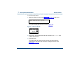
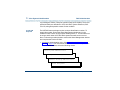
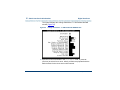
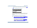
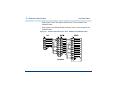
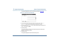
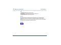
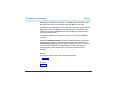
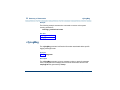
•
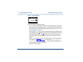
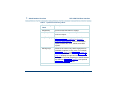
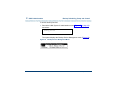
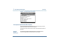
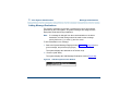
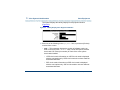
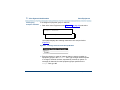
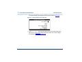
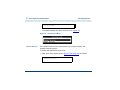
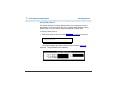
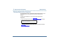
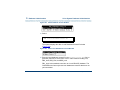
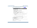
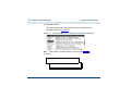
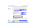
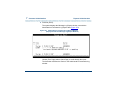
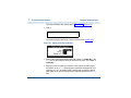
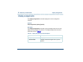
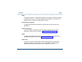
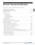
The system displays menus, screens, and windows. Menus (Figure 1)
present options from which you can choose to view another menu, or a
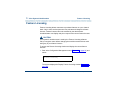
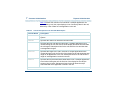
screen or window. Screens and windows both show (Figure 2 on page
xxviii and Figure 3 on page xxix) and request (Figure 4 on page xxix and
Figure 5 on page xxx) system information.
Figure 1.
Example of a UCS 1000 R4.2 Menu
UCS 1000 R4.2 Administration 585-313-507
Issue 3 April 2000 xxvii
About This Book
Conventions Used in This Book
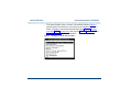
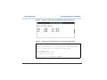
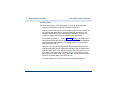
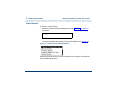
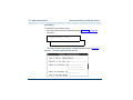
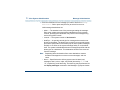
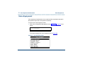
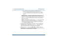
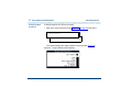
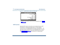
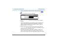
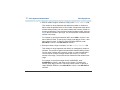
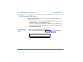
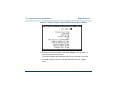
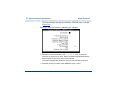
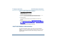
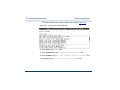
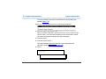
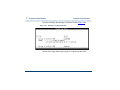
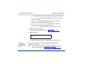
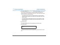
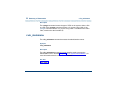
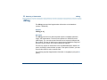
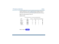
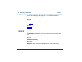
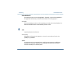
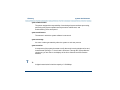
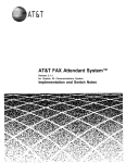
Figure 2.
Example of a UCS 1000 R4.2 Screen Showing Information
UnixWare Installation
Primary Hard Disk Partitioning
In order to install LINCS, you should reserve a UNIX system
partition (a portion of your hard disk’s space) containing 100%
of the space on your primary hard disk. After you press ’ENTER’
you will be shown a screen that will allow you to create new
partitions, delete existing partitions or change the active
partition of your primary hard disk (the partition that your
computer will boot from).
WARNING: All files in any partition(s) you delete will be
destroyed. If you wish to attempt to preserve any files from an
existing UNIX system, do not delete its partitions(s).
The UNIX system partition that you intend to use on the primary
hard disk must be at lease 4200 MBs and labeled “ACTIVE.”
Press ’ENTER’ to continue
UCS 1000 R4.2 Administration 585-313-507
Issue 3 April 2000 xxviii
About This Book
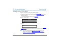
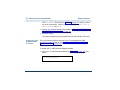
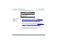
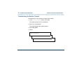
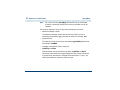
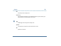
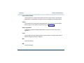
Conventions Used in This Book
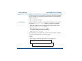
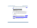
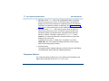
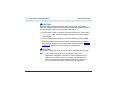
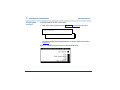
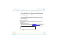
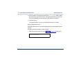
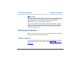
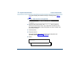
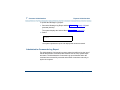
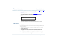
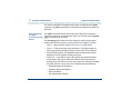
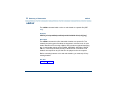
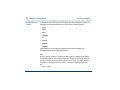
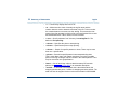
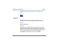
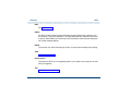
Figure 3. Example of a UCS 1000 R4.2 Window Showing Information
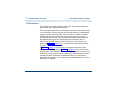
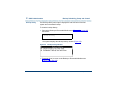
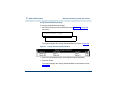
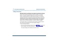
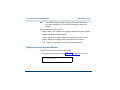
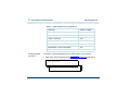
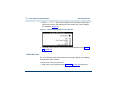
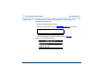
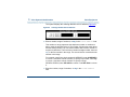
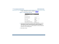
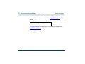
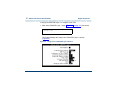
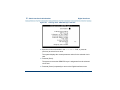
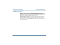
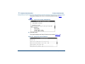
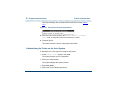
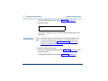
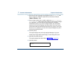
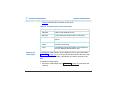
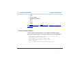
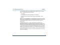
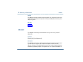
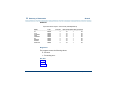
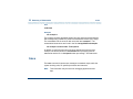
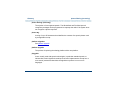
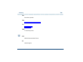
Figure 4.
Example of a UCS 1000 R4.2 Screen Requesting Information
UNIX System Installation
Set Slice Sizes
Please select whether you would like the recommended slice
sizes or would like to customize the slice sizes.
Your choices are:
1. Recommended Slice Sizes
2. Customize Slice Sizes
Press ’1’ or ’2’ followed by ’ENTER’: 1
UCS 1000 R4.2 Administration 585-313-507
Issue 3 April 2000 xxix
About This Book
Conventions Used in This Book
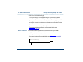
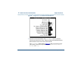
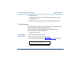
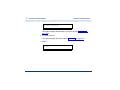
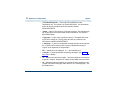
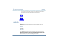
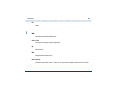
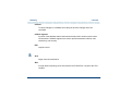
Figure 5.
Keyboard and
Telephone Keypad
Representations
•
Example of a UCS 1000 R4.2 Window Requesting Information
Keys that you press on your terminal or PC are represented as capitalized
BO LD text. For example, an instruction to press the Enter key is shown
as
Press EN TE R .
•
Two or three keys that you press at the same time on your terminal or PC
(that is, you hold down the first key while pressing the second and/or third
key) are represented as a series of small, capitalized B O LD text
separated by the p lus sign (+) . For example, an instruction to press and
hold “Alt” while typing the letter “d” is shown as
Press ALT+ D
•
Function keys on your terminal, PC, or system screens, also known as
soft keys, are represented as capitalized BO LD text followed by the
function or value of that key enclosed in parentheses. For example, an
instruction to press function key 2 is shown as
Press F2 (Choices).
UCS 1000 R4.2 Administration 585-313-507
Issue 3 April 2000 xxx
About This Book
Conventions Used in This Book
•
Keys that you press on your telephone keypad are represented as bold
text. For example, an instruction to press the first key on your telephone
keypad is shown as
Press 1 to record a message.
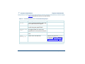
Screen Displays
•
System messages, field names, and prompts that appear on the screen
are shown in typewriter text, as shown in the following examples:
~ Enter the number of ports to be dedicated to outbound traffic in the
Maximum Simultaneous Ports field.
~ Enter y in the Message Transfer? field.
~ The system displays the following message:
Installation in progress.
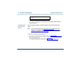
•
The sequence of menu options that you must select to display a specific
screen or submenu appears in a series of boxes.
Example:
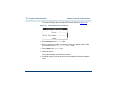
Start at the Voice System Administration menu and select:
> Reports
> Message Log Report
UCS 1000 R4.2 Administration 585-313-507
Issue 3 April 2000 xxxi
About This Book
Conventions Used in This Book
In this example, you would access the Voice System Administration menu
and select the Reports menu. From the Reports menu, you would then
select the Message Log Report window.
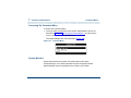
Some Screen
Simulations
Text in a simulated screen display appears in typewriter text.
Example:
QuickStart - Data Recovery Rescue
Copyright(c) 1997-1999 by Enhanced Software Technologies, Inc.
Serial# 8200-999
Version: 1.3.17
Backup
System
Items That May or
May Not Appear
Verify
System
Recover
System
Duplicate
Diskette
Configure
QuickStart
Exit
and Reboot
Grayed-out type represents optional items that may or may not appear in a
given display.
Example:
Once the backup is complete, the system displays a message similar to
the following:
The Differential UNIX backup is now complete. Please remove
the tape and label it as "Differential UNIX Backup, created
August 30, 1999."
UCS 1000 R4.2 Administration 585-313-507
Issue 3 April 2000 xxxii
About This Book
Conventions Used in This Book
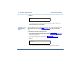
Other Typography
Command Text
•
Literal values, commands, and text that you type in or enter appear in
bold type, as in the following examples:
Example 1:
Enter change-switch-time-zone at the Enter command: prompt.
Example 2:
Type high or low in the Speed: field.
•
Command variables are shown in bold italic type when they are part of
what you must type in, and in italics when they are not part of the
command line, for example:
Enter ch ma machine_name, where machine_name is the name of
the call delivery machine you just created.
•
Command options are shown inside square brackets, for example:
Enter connect switchname [-c] [-b | -w]
Cross-References
and Hypertext
Blue, underlined type indicates a cross reference or hypertext link that takes
you to another location in the document when you click on it.
UCS 1000 R4.2 Administration 585-313-507
Issue 3 April 2000 xxxiii
About This Book
Safety and Security Alert Labels
Safety and Security Alert Labels
This book uses the following symbols to call your attention to potential
problems that could cause personal injury, damage to equipment, loss of
data, service interruptions, or breaches of toll fraud security:
! CAUTION:
Indicates the presence of a hazard that if not avoided can or will cause minor
personal injury or property damage, including loss of data.
! WARNING:
Indicates the presence of a hazard that if not avoided can cause death
or severe personal injury.
! DANGER:
Indicates the presence of a hazard that if not avoided will cause death or
severe personal injury.
! SECURITY ALERT:
Indicates the presence of a toll fraud security hazard. Toll fraud is the
unauthorized use of a telecommunications system by an unauthorized
party.
UCS 1000 R4.2 Administration 585-313-507
Issue 3 April 2000 xxxiv
About This Book
Related Resources
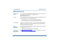
Related Resources
Updates to the
Product
The following Web site displays any updates or exceptions to the product that
have occurred after the publication of this document:
http://glsdocs.lucent.com
Training
For more information on UCS 1000 R4.2 training, call the BCS Education and
Training Center at one of the following numbers:
•
Organizations within Lucent Technologies (904) 636-3261
•
Lucent Technologies customers and all others (800) 256-8988
Documentation
Appendix A, “Documentation Guide,” in UCS 1000 R4.2 System Description,
585-313-209, provides an overview of all the books in the UCS 1000 R4.2
library that are mentioned in this book.
Additional
Suggested
Documentation
It is suggested that you also obtain and use the following book for information
on security and toll fraud issues:
•
Obtaining Printed
Versions of the
Documentation
GBCS Products Security Handbook, 555-025-600
See Printing the Documentation on page xxxvii for information on how to print
this document.
UCS 1000 R4.2 Administration 585-313-507
Issue 3 April 2000 xxxv
About This Book
Related Resources
You can also order the printed documents by calling 1-888-582-3688 or
visiting the Customer Information Center (CIC) website at:
http://www.lucent.com/cgi-bin/CIC_store.cgi
Using the CD-ROM Documentation
Lucent Technologies ships the documentation in electronic form. Using the
Adobe Acrobat Reader application, you can read these documents on a
Windows PC, on a Sun Solaris workstation, or on an HP-UX workstation.
Acrobat Reader displays high-quality, print-like graphics on both UNIX and
Windows platforms. It provides scrolling, zoom, and extensive search
capabilities, along with online help. A copy of Acrobat Reader is included with
the documents.
Setting the Default
Magnification
You can set your default magnification by selecting File | Preferences |
General. We recommend the Fit Page option.
Adjusting the
Window Size
On HP and Sun workstations, you can control the size of the reader window
by using the -geometry argument. For example, the command string
acroread -geometry 900x900 mainmenu.pdf opens the main menu with a
window size of 900 pixels square.
Hiding and
Displaying
Bookmarks
By default, the document appears with bookmarks displayed on the left side
of the screen. The bookmarks serve as a hypertext table of contents for the
UCS 1000 R4.2 Administration 585-313-507
Issue 3 April 2000 xxxvi
About This Book
Related Resources
chapter you are viewing. You can control the appearance of bookmarks by
selecting View | Page Only or View | Bookmarks and Page.
Using the Button
Bar
The button bar can take you to the book’s Index, table of contents, main
menu, and glossary. It also lets you update your documents. Click the
corresponding button to jump to the section you want to read.
Using Hypertext
Links
Hypertext-linked text appears in blue, italics, and underlined. These links are
shortcuts to other sections or books.
Navigating with
Double Arrow Keys
The double right and double left arrows (
and
) at the top of the
Acrobat Reader window are the go-back and go-forward functions. The goback button takes you to the last page you visited prior to the current page.
Typically, you use
to jump back to the main text from a cross reference or
illustration.
Searching for
Topics
Acrobat has a sophisticated search capability. From the main menu, select
Tools | Search. Then choose the Master Index.
Displaying Figures
If lines in figures appear broken or absent, increase the magnification. You
might also want to print a paper copy of the figure for better resolution.
Printing the
Documentation
Note:
For information on ordering printed copies of the documents, see
Obtaining Printed Versions of the Documentation on page xxxv.
UCS 1000 R4.2 Administration 585-313-507
Issue 3 April 2000 xxxvii
About This Book
Related Resources
If you would want to read the documentation in paper form rather than on a
computer monitor, you can print all or portions of the online screens.
Printing an Entire Document
To print an entire document:
1 From the documentation main menu screen, select one of the print-
optimized documents. Print-optimized documents print two-screens to a
side, both sides of the sheet on 8.5x11-in or A4 paper.
2 Select File | Print.
3 Enter the page range you want to print, or select All. Note that the print
page range is different from the page numbers on the documents (they
print two to a page).
4 After the document is printed, close the file. Do not leave this file open
while viewing the electronic documents.
Printing Part of a Document
To print a single page or a short section, you can print directly from the online
version of the document:
1 Select File | Print.
2 Enter the page range you want to print, or select Current.
The document is printed, one screen per side, two sides per sheet.
UCS 1000 R4.2 Administration 585-313-507
Issue 3 April 2000 xxxviii
About This Book
How to Comment on This Book
How to Comment on This Book
A comment card is included at the back of this book. While we have tried to
make this document fit your needs, we are interested in your suggestions for
improving it and urge you to complete and return a comment card to us. If the
comment card has been removed from this book, send you comments to the
address below. Be sure to include the name and document number of this
book, UCS 1000 R4.2 Administration, 585-313-507.
Lucent Technologies
GLS Information Development Division
Room 22-2H15
11900 North Pecos Street
Denver, Colorado 80234-2703 US
You may also fax your comments to the attention of the Lucent Technologies
UCS 1000 R4.2 writing team at (303) 538-1741.
UCS 1000 R4.2 Administration 585-313-507
Issue 3 April 2000 xxxix
1 Administration Overview
Overview
This chapter provides an overview of system administration and is designed
to familiarize you with the UCS 1000 R4.2 user interface and the system
administration process including:
•
User interface overview
•
User interface components
•
The administration menus
User Interface Overview
A user interface is a method by which a computer user accesses the
information on the computer. For example, Microsoft Windows is a graphical
user interface (also known as GUI).
The UCS 1000 R4.2 user interface is menu-driven; that is, you select an
option from a list to display another menu or window. You can display more
than one menu or window concurrently, but only the last one displayed is
UCS 1000 R4.2 Administration 585-313-507
Issue 3 April 2000 1
1
Administration Overview
UCS 1000 R4.2 User Interface
active. To return to the previous menu or window, you can cancel the active
one.
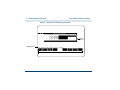
UCS 1000 R4.2 User Interface
Administering the voice system through the administrative screens involves
many activities, and all share a common user interface. Although the
information on the screen changes often, the information arrangement does
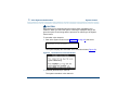
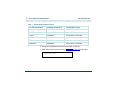
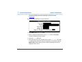
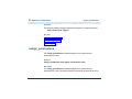
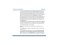
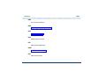
not change. The typical screen contents is as follows (Figure 6 on page 3):
•
Menu and/or window
•
Message line
•
Function key labels
UCS 1000 R4.2 Administration 585-313-507
Issue 3 April 2000 2
1
Administration Overview
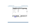
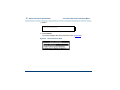
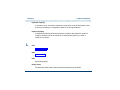
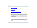
UCS 1000 R4.2 User Interface
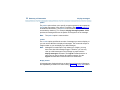
Figure 6. Sample UCS 1000 R4.2 System Screen
Menu or
Window
Message Line
Function Key Labels
UCS 1000 R4.2 Administration 585-313-507
Issue 3 April 2000 3
1
Administration Overview
UCS 1000 R4.2 User Interface
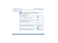
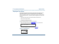
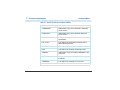
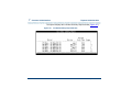
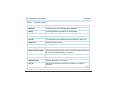
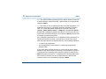
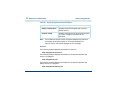
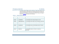
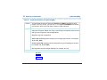
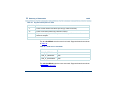
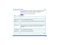
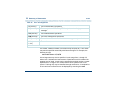
Cursor Movement Keys
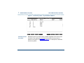
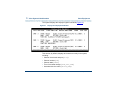
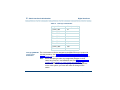
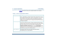
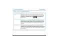
Table 1 lists the keys used to maneuver within a menu or window. They are
referred to throughout this book as the cursor movement keys.
Table 1.
Cursor Movement Keys
Type of Movement
Key
Move to next line in menu, list, or text; “wrap” from
last item to first item in a menu or form
Move to previous line in menu, list, or text; “wrap”
from first item to last item in a menu or form
Move down one “screenful”
PgD w
Move up one “screenful”
PgU p
Move to next field in a screen or window
Tab , or E nter
Move to previous field in a screen or window
Shi ft , or Tab
Move to next character within a field
Move to previous character within a field
Delete character to the left of the cursor
UCS 1000 R4.2 Administration 585-313-507
Back Space
Issue 3 April 2000 4
1
Administration Overview
UCS 1000 R4.2 User Interface
Menus and Windows
You use menus and windows to exchange information with the voice system.
This exchange may involve activities such as making menu selections or
populating fields. Since the display may contain more than one menu or
window at the same time, each menu/window is outlined so that it is clear
what information it contains. At any given time, only one menu or window on
screen is designated as active.
Menus
A menu allows you to select an option that takes you to the next menu or
window (Figure 7).
Figure 7. Sample Menu
UCS 1000 R4.2 Administration 585-313-507
Issue 3 April 2000 5
1
Administration Overview
UCS 1000 R4.2 User Interface
The components of a menu include:
•
Title — The title describes the information contained within the menu, or
the tasks you can accomplish using it. In this book, titles are shown with
the first letter of each word capitalized, followed by the word menu, such
as the Configuration Management menu.
•
Scroll Indicator — The scroll bar indicates whether there is additional text
to be displayed. The
indicates there is more information to view below
what is presently shown. The
indicates there is more information to
view above what is currently displayed. Not every menu has a scroll
indicator.
Selecting a Menu Item
To select a menu item, highlight it using one of the following methods and
then press Enter:
•
Use the cursor movement keys to move the highlight bar:
~ Press
to move the highlight bar down.
~ Press
to move the highlight bar up.
Menus have a “rollover” feature. When the cursor reaches the last item
of the menu, press
to return to the first menu item. If the cursor is
highlighting the first menu item, press
to move to the last menu
item.
UCS 1000 R4.2 Administration 585-313-507
Issue 3 April 2000 6
1
Administration Overview
•
UCS 1000 R4.2 User Interface
Type the first character(s) of the menu line. The system highlights the first
menu item beginning with that letter. For example, in Figure 7 on page 5,
type S to select System Control. If there is another menu item beginning
with “s,” type more characters.
The menu items are not case-sensitive; that is, typing A is the same as
typing a. If you type a letter for which there is no matching item, the
system “beeps” and does not move the highlight bar.
Windows
A window allows you to enter and view information, and can range in size.
See Figure 8 and Figure 9 on page 8.
Figure 8. Sample Window
UCS 1000 R4.2 Administration 585-313-507
Issue 3 April 2000 7
1
Administration Overview
UCS 1000 R4.2 User Interface
Figure 9. Sample Window
The components of a window include:
•
Title — The title describes the information contained within the window, or
the tasks you can accomplish using it. In this book, titles are shown with
the first letter of each word capitalized, followed by the word window, such
as Voice Equipment window.
•
Scroll Indicator — The scroll bar indicates whether there is additional text
to be displayed. The
indicates there is more information to view below
what is presently shown. The
indicates there is more information to
view above what is currently displayed. Not every window has a scroll
indicator.
•
Fields — Fields are the areas on a window where you enter information.
For example, in Figure 6 on page 3 the fields are Channel Numbers,
Service Name, and Startup Service. Use the TAB or E NT ER keys to
move through the fields in succession.
Menus do not have fields.
UCS 1000 R4.2 Administration 585-313-507
Issue 3 April 2000 8
1
Administration Overview
UCS 1000 R4.2 User Interface
Populating Fields
There are three ways to enter information in a field, as described below.
•
Type the first character or first few characters of the entry.
With the cursor positioned on the field, begin to type the entry. As soon as
you type enough characters to uniquely identify the desired entry, the
system automatically supplies the remaining characters. If the entry is
invalid, the system beeps and removes the invalid characters.
For example, given the Day: field in Figure 10 on page 10, assume that
valid entries are the names of the days in the week. When you type M, the
system fills in the entire word Monday because there is only one valid
entry that begins with M.
However, if you type S, the system waits before filling in the day of the
week because there are two valid entries that begin with S (Saturday and
Sunday). At this point, if you type a, the system fills in the word Saturday.
If you type u, the system fills in the word Sunday. This technique is not
case-sensitive. In other words, typing either M or m in the above example
results in the system filling in the word Monday.
•
Press F2 (Choices) for a list of valid entries for the particular field.
UCS 1000 R4.2 Administration 585-313-507
Issue 3 April 2000 9
1
Administration Overview
UCS 1000 R4.2 User Interface
Figure 10. Fields in the Call Data Summary Report Window
•
Type the entire entry.
Move to the desired field and type the entire entry. While in a field, you
can also edit the entry.
•
Use the CHOICES screen selections.
Press F 2 (Choices) to open a menu that shows the available choices for a
field. Select an option as you would in a standard menu. The content of
the CHOICES menu varies depending on the situation. Sometimes no
CHOICES menu is available for a screen or window.
Message Line
The message line, if present on the screen, contains a brief instruction to help
you decide what to do next. The message line also reports the successful or
unsuccessful completion of a task.
UCS 1000 R4.2 Administration 585-313-507
Issue 3 April 2000 10
1
Administration Overview
UCS 1000 R4.2 User Interface
Function Keys
Your keyboard has eight to twelve function keys. The system uses the first
eight function keys, labeled F 1 through F 8 .
The boxed labels at the bottom of the display correspond to the function keys
on your keyboard. Function keys are the means by which you command the
system to perform a function within the active menu or window. The label
describes the instruction that is sent to the system when you press the
corresponding function key. The commands, and therefore the labels, that
are available at any given time vary depending on the active menu or
window. Menus and windows may have one or two rows of function key
labels. See Figure 11 on page 12 for an example of a window with function
key labels.
In Figure 11 on page 12 you press F1 to access the Help screen for the
System Monitor window. Also in Figure 11 on page 12, notice that the label
for F4 is blank. This indicates that no command is issued if you press the F 4
function key. If you press an inactive function key, the system beeps and the
message line either indicates an undefined function key or continues to
display the last message. The function key labels displayed apply only to the
active menu or window.
UCS 1000 R4.2 Administration 585-313-507
Issue 3 April 2000 11
1
Administration Overview
UCS 1000 R4.2 User Interface
Figure 11. Function Key Labels — System Monitor Window
Standard Function
Key Labels
Standard function key labels remain constant regardless of the active menu
or window. They represent commands that are valid for every menu or
window in the system. See Table 2 on page 13 for a description of standard
function key labels.
UCS 1000 R4.2 Administration 585-313-507
Issue 3 April 2000 12
1
Administration Overview
Table 2.
Optional Function
Key Labels
UCS 1000 R4.2 User Interface
Standard Function Key Labels
Key
Description
F1 Help
Opens an online help window. See Online Help on page
17 for more information about online help.
F6 Cancel
Closes the active screen and cancels any additions,
deletions, or changes made. The screen that
immediately precedes the just-closed screen becomes
the active screen. If there is an activity in progress, such
as making a backup copy of an application on a floppy
disk, pressing F 6 (CANCEL) does not interrupt the
operation.
F7 Cmd-Menu
Opens the Command Menu. Options include System
Monitor, Trace Service, and Exit. See Command Menu
on page 297 in Chapter 7, Common Administration , for
more information.
The optional function key labels change based on the active menu or window,
and provide commands that are unique to the menu or window. See Table 3
on page 14 for a description of optional function key labels.
UCS 1000 R4.2 Administration 585-313-507
Issue 3 April 2000 13
1
Administration Overview
Table 3.
UCS 1000 R4.2 User Interface
Optional Function Key Labels
Function Key
Label
Description
F 2 (Choices)
Opens a menu screen containing choices for the
current field, if there is a finite set of choices for a
particular field. Move the cursor to the field you want
to fill and press F2 (CHOICES). The CHOICES
menu opens, displaying the options available for that
field.
F 2 (Prevpage)
Scrolls back one full page, towards the beginning of
text that is too long to fit within the active screen or
window.
F 3 (Nextpage)
Scrolls forward, toward the end of text that is too
long to fit within the active screen, menu, or window.
For example, pressing F3 in Figure 11 on page 12
orders the system to move to the next page, while
pressing F 3 in Figure 12 on page 16 sounds a beep,
but does nothing else because that key is “empty.”
F 3 (Save)
Preserves all changes made to the screen.
F 4 (Top)
Scrolls toward the top of a page.
1 of 2
UCS 1000 R4.2 Administration 585-313-507
Issue 3 April 2000 14
1
Administration Overview
Table 3.
UCS 1000 R4.2 User Interface
Optional Function Key Labels
Function Key
Label
Description
F 5 (Bottom)
Scrolls toward the bottom of a page.
F 6 (Print)
Prints the information provided by the active screen,
such as a report.
F 7 (Frm-Mgmt)
Opens the Frame Management Menu. See
Command Menu on page 297 in Chapter 7,
Common Administration , for more information.
Options include list, move, refresh, and UNIX
system.
F 8 Chg-Keys
Switches the function key labels displayed from
standard to optional, or vice versa. For example,
Figure 11 on page 12 and Figure 12 on page 16
show the System Monitor window. Figure 12 on
page 16 displays the optional function key labels
through the use of F8 (Chg-Keys) to switch between
the standard (Figure 11 on page 12) and optional
(Figure 12 on page 16) labels.
2 of 2
UCS 1000 R4.2 Administration 585-313-507
Issue 3 April 2000 15
1
Administration Overview
UCS 1000 R4.2 User Interface
Figure 12. Change Keys — System Monitor Screen
Note:
In Figure 12, the H ost M on function key selection does not
appear if host software is not installed.
UCS 1000 R4.2 Administration 585-313-507
Issue 3 April 2000 16
1
Administration Overview
Online Help
Online Help
Most screens and windows have a companion text window that contains
helpful reference information. Figure 13 shows the help screen associated
with the Database Access ID Table window. The system online help windows
are not designed to be a substitute for this book. They briefly describe each of
your options for a given menu or window. Press F1 to access online help.
Figure 13. Sample Online Help Screen, Database Access ID Table
UCS 1000 R4.2 Administration 585-313-507
Issue 3 April 2000 17
1
Administration Overview
Accessing the Administration Menus
Accessing the Administration Menus
To access the administration menu:
1 At the Console Login: prompt, enter root
The system prompts you for a password.
2 Enter your root password.
The system displays the system prompt #.
3 Enter one of the following commands at the prompt:
~ To display the administration menu, enter cvis_mainmenu
The system displays the administration menu (Figure 14).
Figure 14.
Administration Menu
~ To display the Voice System Administration menu, enter cvis_menu
UCS 1000 R4.2 Administration 585-313-507
Issue 3 April 2000 18
1
Administration Overview
Accessing the Administration Menus
! CAUTION:
Do not create multiple simultaneous cvis_menu processes. This could
severely impact performance and may lock up the system.
The system displays the Voice System Administration menu (Figure
15).
Figure 15. Voice System Administration Menu
See Chapter 3, Voice System Administration , for more information and
procedures on voice system administration.
UCS 1000 R4.2 Administration 585-313-507
Issue 3 April 2000 19
1
Administration Overview
Accessing the Administration Menus
Administration Menu Options
From the administration menu, you can initiate UNIX System Administration
and Voice System Administration, or you may exit.
UNIX System
Administration
From the UNIX System Administration menu, you can set up a variety of
generic software operations including backups, printer operations, and
peripheral setup. See Chapter 2, UNIX Administration , for more information
and procedures on UNIX administration.
Voice System
Administration
From the Voice System Administration menu, you can begin your session for
administering the system, such as application packages or reports. See
Chapter 3, Voice System Administration , for more information and
procedures on voice system administration.
Exit
Exit takes you out of the administration menus and returns you to the UNIX
system prompt.
Press F 6 (Cancel) from almost any place in the Administration menu
structure to close the active window and return to the previous menu. If you
press F6 (Cancel) enough times, depending on how deep into the menus you
are, you will eventually exit the menu structure completely and return to the
operating system prompt.
UCS 1000 R4.2 Administration 585-313-507
Issue 3 April 2000 20
1
Administration Overview
Note:
Accessing the Administration Menus
F 6 (Cancel) does not exit from the UNIX System Administration
menus. See Exit UNIX System Administration Menu on page 57 in
Chapter 2, UNIX Administration , for the procedure to exit from the
UNIX System Administration menus.
UCS 1000 R4.2 Administration 585-313-507
Issue 3 April 2000 21
2 UNIX Administration
Overview
This chapter describes the UnixWare™ system administration user interface,
the procedures to access the UnixWare administration menu, and the
procedures to perform basic UnixWare-level administration.
The sections in this chapter are arranged in the same order as the
administration services in the UnixWare administration main menu.
UnixWare Documentation
For additional information on UnixWare administration, see the UnixWare
documentation. Start with the System Administration Volume 1 for an
overview of the UnixWare system administration and for an introduction to
administration concepts and procedures. Many of the procedures in this
chapter reference other UnixWare system administration books. Follow the
referenced procedures for additional information.
UCS 1000 R4.2 Administration 585-313-507
Issue 3 April 2000 22
2
UNIX Administration
UNIX System Administration Access
UNIX System Administration Access
To access SYSADM (the OA&M menu interface of UnixWare):
1 At the Console Login: prompt, enter root
The system prompts you for a password.
2 Enter your root password.
The system displays the system prompt #.
3 Enter cvis_mainmenu
The system displays the Administration menu (Figure 16).
Figure 16.
Administration Menu
UCS 1000 R4.2 Administration 585-313-507
Issue 3 April 2000 23
2
UNIX Administration
UNIX System Administration Access
4 Select:
> UNIX System Administration
The system displays the UNIX System V Administration menu (Figure 17
on page 24).
Figure 17. UNIX System V Administration Menu
UCS 1000 R4.2 Administration 585-313-507
Issue 3 April 2000 24
2
UNIX Administration
Application Administration
All of the procedures in this book assume that you are using the user
interface menus. The procedures provide references to the books detailing
command line interfaces when possible.
Application Administration
The Application Administration menu provides menus and tasks for
administering custom applications. Application developers can use this option
to place menus from which to administer add-on or custom applications.
Backup Scheduling, Setup and Control
The Backup Service menu provides two backup options: basic and extended.
Back-up files can be stored on either tape or diskettes.
Note:
Diskettes must be UNIX formatted when you begin this procedure.
Tapes can be unformatted.
See “Backing Up the UCS 1000 R4.2 System” in Chapter 3, “Common
System Procedures,” in UCS 1000 R4.2 System Reference, 585-313-210, for
information on when to conduct backups.
UCS 1000 R4.2 Administration 585-313-507
Issue 3 April 2000 25
2
UNIX Administration
Backup Scheduling, Setup and Control
The basic backup services allow you to:
•
Display the date and time of the last system and incremental backup.
•
Conduct a backup of all files or only selected files in your HOME directory.
•
Add, change, delete, or display backup requests.
•
Back up all system and user files that have been modified or created
since your voice system was installed.
The extended backup services allow you to:
•
Determine the backup rotation period.
•
Specify how backups are to be done for file systems and data partitions.
•
Display the backup history and backup status logs.
•
Establish lists of files that should not be backed up.
•
Respond to system prompts during backup jobs.
•
Schedule backups and the reminder messages that backups should be
done.
Note:
If you want to back up and restore speech files, see the spsav
command in Appendix A, Summary of Commands.
UCS 1000 R4.2 Administration 585-313-507
Issue 3 April 2000 26
2
UNIX Administration
Backup Scheduling, Setup and Control
To access backup services:
1 Start at the UNIX System V Administration menu (Figure 17 on page 24)
and select:
> backup_service
The system displays the Backup Service Management menu (Figure 18).
Figure 18. Backup Service Management Menu
UCS 1000 R4.2 Administration 585-313-507
Issue 3 April 2000 27
2
UNIX Administration
Backup Scheduling, Setup and Control
Basic Backup
To perform a basic backup:
1 Start at the Backup Service Management menu (Figure 18 on page 27)
and select:
> basic
The system displays the Backup to Removable Media menu (Figure 19).
Figure 19. Backup to Removable Media Menu
Use the procedures below to access the different menu options of the Backup
to Removable Media menu.
UCS 1000 R4.2 Administration 585-313-507
Issue 3 April 2000 28
2
UNIX Administration
Backup History
Backup Scheduling, Setup and Control
The Backup History menu option displays the date and time of the last
system and incremental backup.
To view the backup history:
1 Start at the Backup to Removable Media menu (Figure 19 on page 28)
and select:
> Backup History
The system displays the Backup History window (Figure 20).
Figure 20. Backup History Window
2 Press F3 (Cont) to return to the Backup to Removable Media menu
(Figure 19 on page 28).
UCS 1000 R4.2 Administration 585-313-507
Issue 3 April 2000 29
2
UNIX Administration
Backup of All
Personal Files
Backup Scheduling, Setup and Control
A personal backup copies all the files in your HOME (or personal) directory to
either tape or formatted diskettes.
To back up all files in your personal directory:
1 Start at the Backup to Removable Media menu (Figure 19 on page 28)
and select:
> Personal Backup
> Backup Files under /
The system displays the Select Removable Media menu (Figure 21).
Figure 21. Select Removable Media Menu
UCS 1000 R4.2 Administration 585-313-507
Issue 3 April 2000 30
2
UNIX Administration
Backup Scheduling, Setup and Control
2 Select the removable media type.
The system displays a message showing the approximate number of
diskettes or tapes, and the time required to backup the HOME directory.
The system prompts you to insert the first diskette or tape. The system
periodically prompts you to insert more diskettes or tapes until the backup
is complete.
3 Press EN TE R when the backup is complete.
The system redisplays the Backup to Removable Media menu
(Figure 19 on page 28).
Backup of Selected
Personal Files
This procedure backs up selected files and directories in your HOME
directory to either tape or formatted diskette.
To back up selected personal files or directories:
1 Start at the Backup to Removable Media menu (Figure 19 on page 28)
and select:
> Personal Backup
> Backup Files under /
UCS 1000 R4.2 Administration 585-313-507
Issue 3 April 2000 31
2
UNIX Administration
Backup Scheduling, Setup and Control
The system displays the Select Removable Media menu (Figure 21 on
page 30).
2 Select the removable media type.
The system displays the Selective Backup of Files under / window
(Figure 22).
Figure 22. Selective Backup of Files under / Window
3 Enter the file names and directory names to be backed up. Separate each
entry with a space in the Files or directories to back up: field.
Note:
All files and directories must be in the HOME directory or in a
subdirectory of HOME.
4 Press F3 (Save).
The system displays a message showing the approximate number of
diskettes or tapes, and the time required to backup the HOME directory.
UCS 1000 R4.2 Administration 585-313-507
Issue 3 April 2000 32
2
UNIX Administration
Backup Scheduling, Setup and Control
The system prompts you to insert the first diskette or tape. The system
periodically prompts you to insert more diskettes or tapes if they are
needed until the backup is complete.
5 Press EN TE R when the backup is complete.
The system redisplays the Backup to Removable Media menu
(Figure 19 on page 28).
Schedule a Backup
to Tape
The Schedule Backup to Tape menu option allows you to:
•
Add a system or incremental backup.
•
Change a previously scheduled backup request.
•
Delete a previously scheduled backup request.
•
Display the scheduled backup list.
Note:
You need either root or system administration privileges to add,
change, or delete a scheduled backup. You do not need those
privileges to display a list of scheduled backups.
UCS 1000 R4.2 Administration 585-313-507
Issue 3 April 2000 33
2
UNIX Administration
Backup Scheduling, Setup and Control
Add a Backup
To schedule a new backup to tape:
1 Start at the Backup to Removable Media Menu (Figure 19 on page 28)
and select:
> Schedule Backup to Tape
> Add
The system displays the Schedule a System Backup window (Figure 23).
Figure 23. Schedule a System Backup Window
UCS 1000 R4.2 Administration 585-313-507
Issue 3 April 2000 34
2
UNIX Administration
Backup Scheduling, Setup and Control
2 Press F2 (Choices) to toggle between System Backup and Incremental
System Backup in the Type of Backup: field. A system backup (field
default) performs a back up of all system and user files installed or
modified since the voice system was first installed. An incremental backup
performs a back up of all system and user files since the last backup.
3 Use one of the following methods to enter a value in the Month(s) of
the Year: field:
~ Type a number from 1 to 12 where January is 1 and December is 12 to
indicate a single month.
~ Type two numbers separated by a hyphen to indicate a range of
months. For example, type 1-8 to instruct the system to perform
backups of January through August.
~ Press F 2 (Choices) and press F2 (Mark) to select one or more months.
Press F3 (Enter) to save the selected month or months and return to
the Month(s) of the Year: field.
The default value is “all,” to back up all months.
4 Use one of the following methods to enter a value in the Day(s) of the
Month: field:
~ Type a number from 1 to 31 corresponding to the day of the month to
indicate a single day.
UCS 1000 R4.2 Administration 585-313-507
Issue 3 April 2000 35
2
UNIX Administration
Backup Scheduling, Setup and Control
~ Type two numbers separated by a hyphen to indicate a range of days.
For example, type 14-20 to instruct the system to perform a backup
every day from day 14 through day 20 of the month.
~ Press F2 (Choices) and press F2 (Mark) to select one or more days.
Press F3 (Enter) to save the selected day or days and return to the
Day(s) of the Month: field.
The default is “all,” to back up all days of the month.
5 Use one of the following methods to enter a value in the Day(s) of the
Week: field:
~ Type the first letter of the day to indicate a single day of the week, or
Press F2 (Choices) to select a single day from a menu.
Note:
Sunday is Su and Thursday is Th. Every other day of the week is
indicated by its first letter.
~ Type two days, separated by a hyphen to indicate a range of days. For
example, type M-Th to instruct the system to perform a backup every
Monday, Tuesday, Wednesday, and Thursday.
~ Press F2 (Choices) and press F2 (Mark) to select one or more days.
Press F3 (Enter) to save the selected day(s) of the week and return to
the Day(s) of the Week: field.
The default is “all,” to back up all days of the week.
UCS 1000 R4.2 Administration 585-313-507
Issue 3 April 2000 36
2
UNIX Administration
Backup Scheduling, Setup and Control
6 Set the Time of Day: field:
a Type a number in the Hours portion of the field to indicate the hour,
where 00 is midnight and 23 is 11:00 p.m. Or, press F 2 (Choices) to
select from a menu.
.
b Press
The system places the cursor in the minutes portion of the field.
c Type a number from 0 to 59 to indicate the minutes past the hour.
The default time is 02:00, to start the backup at 2:00 a.m.
7 Press F3 (Save).
The system displays a confirmation window that asks whether you want to
continue to schedule the backup.
8 Do one of the following:
~ To confirm the backup schedule, press F3 (Cont).
The system returns to the Schedule Backup to Tape menu.
~ To cancel the backup schedule, press F6 (Cancel).
The system returns to the Schedule Backup to Tape menu.
UCS 1000 R4.2 Administration 585-313-507
Issue 3 April 2000 37
2
UNIX Administration
Backup Scheduling, Setup and Control
Change Scheduled Backup Settings
To change scheduled backup settings:
1 Start at the Backup to Removable Media menu (Figure 19 on page 28)
and select:
> Schedule Backup to Tape
> Change
The system displays the Change Scheduled Backup window (Figure 24).
Figure 24. Change Scheduled Backup Window
2 Select the scheduled backup to be changed and press F2 (Mark).
3 Press F3 (Enter).
The system displays the Change Scheduled Backup Information window
(Figure 25).
UCS 1000 R4.2 Administration 585-313-507
Issue 3 April 2000 38
2
UNIX Administration
Backup Scheduling, Setup and Control
Figure 25. Change Scheduled Backup Information Window
4 Change the information as appropriate. See step 2 through step 6 in Add
a Backup on page 34 for information on how to add data to the fields in
this window.
5 Press F3 (Save).
The system displays a confirmation window that asks whether you want to
continue to schedule the backup.
UCS 1000 R4.2 Administration 585-313-507
Issue 3 April 2000 39
2
UNIX Administration
Backup Scheduling, Setup and Control
6 Do one of the following:
~ To confirm the backup schedule, press F3 (Cont).
The system returns to the Schedule Backup to Tape menu.
~ To cancel the backup schedule, press F6 (Cancel).
The system returns to the Schedule Backup to Tape menu.
Delete a Scheduled Backup
To delete scheduled backups:
1 Start at the Backup to Removable Media menu (Figure 19 on page 28)
and select:
> Schedule Backup to Tape
> Delete
The system displays the Delete Scheduled Backups window (Figure 26
on page 41).
UCS 1000 R4.2 Administration 585-313-507
Issue 3 April 2000 40
2
UNIX Administration
Backup Scheduling, Setup and Control
Figure 26. Delete Scheduled Backups Window
2 Select the scheduled backup to be deleted and press F 2 (Mark). Select
as many of the entries as necessary.
3 Press F3 (Enter).
The system displays a confirmation window to confirm the backups
marked for deletion.
4 Do one of the following:
~ To confirm the backup deletion, press F3 (Cont).
The system returns to the Schedule Backup to Tape menu.
~ To cancel the backup deletion, press F6 (Cancel).
The system returns to the Schedule Backup to Tape menu.
UCS 1000 R4.2 Administration 585-313-507
Issue 3 April 2000 41
2
UNIX Administration
Backup Scheduling, Setup and Control
Display Scheduled Backups
To display a list of scheduled backups:
1 Start at the Backup to Removable Media menu (Figure 19 on page 28)
and select:
> Schedule Backup to Tape
> Display
The system displays the Display Scheduled Backup window (Figure 27).
Figure 27. Display Scheduled Backups Window
2 Press F3 (Cont) or F6 (Cancel) to return to the Schedule Backup to Tape
menu (Figure 19 on page 28).
UCS 1000 R4.2 Administration 585-313-507
Issue 3 April 2000 42
2
UNIX Administration
File System Creation, Checking, and Mounting
Performing Extended Backup Services
See “Backing Up the UCS 1000 R4.2 System” in Chapter 3, “Common
System Procedures," in UCS 1000 R4.2 System Reference, 585-313-210, for
information on when and how to conduct extended backups.
File System Creation, Checking, and Mounting
File Systems administration allows you to:
•
Check for and repair errors on a file system.
•
Set file system defaults.
•
Monitor disk usage for all file systems.
•
Display a list of installed file system types.
•
List files by age or size.
•
Identify the file system type.
•
Create a new file system.
•
Mount or unmount a file system.
UCS 1000 R4.2 Administration 585-313-507
Issue 3 April 2000 43
2
UNIX Administration
Machine Configuration, Display, and Shutdown
Figure 28 shows the options available for file system administration. See
System Files and Devices Reference in the Novell UnixWare documentation
set for additional information about each of these options.
Figure 28. Manage File Systems Menu
Machine Configuration, Display, and Shutdown
Machine administration allows you to:
•
Display system configuration information.
•
Shut down the machine.
UCS 1000 R4.2 Administration 585-313-507
Issue 3 April 2000 44
2
UNIX Administration
Machine Configuration, Display, and Shutdown
•
Reboot the machine.
•
Display a list of users who are logged on.
Figure 29 shows the options available for machine administration. See
System Files and Devices Reference in the Novell UnixWare documentation
set for additional information about each of these options.
Figure 29. Machine Configuration Display and Shutdown Menu
Memory Size Disparity
The system may show that available memory is different than the amount that
is actually available. See “Setting Up the UnixWare Environment," in Chapter
5, “Installing the UCS 1000 R4.2 Base System Software,” in UCS 1000 R4.2
Maintenance, 585-313-126, for information about this disparity.
UCS 1000 R4.2 Administration 585-313-507
Issue 3 April 2000 45
2
UNIX Administration
Network Services Administration
Network Services Administration
Network Services administration allows you to:
•
Make network selections.
•
Manage distributed file systems.
•
Perform name-to-address translations.
•
Manage basic networking.
Figure 30 displays the options available for network services administration.
See Network Administration in the Novell UnixWare documentation set for
additional information about each of these options.
Figure 30. Network Services Management Menu
UCS 1000 R4.2 Administration 585-313-507
Issue 3 April 2000 46
2
UNIX Administration
Port Access Services and Monitors
Port Access Services and Monitors
Ports administration allows you to monitor and service ports, set up quick
terminal, and manage terminal line (tty) settings.
Figure 31 shows the options available for ports administration. See System
Administration Volume 1 in the Novell UnixWare documentation set for
additional information about each of these options.
Figure 31. Service Access Management Menu
Printer Configuration and Services
See Chapter 6, Peripheral Administration , for the procedures to configure a
printer for use with the voice system.
UCS 1000 R4.2 Administration 585-313-507
Issue 3 April 2000 47
2
UNIX Administration
Restore from Backup Data
Restore from Backup Data
Restore service administration allows you to perform basic and extended
restore services.
Note:
If you want to back up and restore speech files, see the spsav
command in Appendix A, Summary of Commands.
Figure 32 shows the options available for restore service administration.
Figure 32. Restore Service Management Menu
Basic Restore Services
Basic restore services allow you to perform a personal restore or a system
restore. Figure 33 shows the options available for the Basic Restore Service.
.
Figure 33. Restore from Removable Media Menu
UCS 1000 R4.2 Administration 585-313-507
Issue 3 April 2000 48
2
UNIX Administration
Restore from Backup Data
Extended Restore Services
Extended restore services allow you to:
•
Specify the login of the operator who should be notified when a request
that requires operation intervention is queued.
•
Respond to restore requests.
•
Restore files, directories, file systems, or a data partition from a backup
archive.
•
Display or modify the status of pending restore requests.
Figure 34 shows the options available for the Extended Restore Service.
Figure 34. Extended Restore Service Menu
UCS 1000 R4.2 Administration 585-313-507
Issue 3 April 2000 49
2
UNIX Administration
Schedule Automatic Task
Schedule Automatic Task
Schedule task administration allows you to add, change, delete, and display
a task scheduled through cron.
Figure 35 shows the options available for schedule task administration. See
System Administration Volume 1 in the Novell UnixWare documentation set
for additional information about each of these options.
Figure 35. Schedule Automatic Task Menu
UCS 1000 R4.2 Administration 585-313-507
Issue 3 April 2000 50
2
UNIX Administration
Security Management
Security Management
Security management allows you to manage the security features on the
system. Currently, this includes only the audit trail facility management.
Figure 36 shows the options available for audit trail facility management. This
menu includes the functions for:
•
Managing audit criteria
•
Enabling and disabling auditing
•
Displaying audit information
•
Displaying and setting event log parameters on the system
Note:
To use the audit subsystem, you must be logged in at the
SYS_PRIVATE security level, be a member of group audit, and be
able to access the commands within the AUD role.
Figure 36. Audit Trail Facility Management Menu
UCS 1000 R4.2 Administration 585-313-507
Issue 3 April 2000 51
2
UNIX Administration
Software Installation and Removal
Software Installation and Removal
Software administration allows you to install software, display information
about software packages, store software without installing it, and remove
software.
Figure 37 shows the options available for software administration. See
System Files and Devices Reference in the Novell UnixWare documentation
set for additional information about each of these options.
Figure 37. Software Installation and Information Management Menu
Note:
All the necessary software installation procedures for the UCS
1000 R4.2 system are described in Chapters 5 through 7 in UCS
1000 R4.2 Maintenance, 585-313-126.
UCS 1000 R4.2 Administration 585-313-507
Issue 3 April 2000 52
2
UNIX Administration
Storage Device Operations and Definition
Storage Device Operations and Definition
Storage devices administration allows you to:
•
Copy information from one volume to another.
•
Display storage device information.
•
Erase the contents of a volume.
•
Configure a storage device on the system.
•
Reconfigure a storage device on the system.
A storage device may be integral disks, diskettes, SCSI data storage devices,
nine-track tapes, and other devices configured on the system. The UCS 1000
R4.2 system uses integral disks (hard disks), diskettes, and tapes as storage
devices.
Figure 38 shows the options available for storage administration. See System
Files and Devices Reference in the Novell UnixWare documentation set for
additional information about each of these options.
UCS 1000 R4.2 Administration 585-313-507
Issue 3 April 2000 53
2
UNIX Administration
System Name, Date and Time, and Initial Password Setup
Figure 38. Storage Device Operations and Definitions Menu
System Name, Date and Time, and Initial Password Setup
System setup administration allows you to administer the following system
characteristics:
•
Environment (date, time, time zone)
•
Passwords
•
Machine name
•
Network node name
•
Initial user logins
UCS 1000 R4.2 Administration 585-313-507
Issue 3 April 2000 54
2
UNIX Administration
System Name, Date and Time, and Initial Password Setup
! CAUTION:
Your system’s machine name is used by the Feature Licensing software. Call
your support center before changing the machine name to avoid losing any of
your feature licenses.
Figure 39 shows the options available for system setup administration.
Figure 39. System Name, Date, Time and Initial Password Setup Menu
UCS 1000 R4.2 Administration 585-313-507
Issue 3 April 2000 55
2
UNIX Administration
User Login and Group Administration
User Login and Group Administration
Users administration allows you to manage logins and groups on your
system, including:
•
Adding users or groups
•
Defining defaults for adding users
•
Listing users or groups
•
Modifying attributes of users or groups
•
Redefining user password information
•
Removing users or groups
Figure 40 shows the options available for users administration. See System
Owner Handbook in the Novell UnixWare documentation set for additional
information about each of these options.
Figure 40.
User Login and Group Administration Menu
UCS 1000 R4.2 Administration 585-313-507
Issue 3 April 2000 56
2
UNIX Administration
Exit UNIX System Administration Menu
Exit UNIX System Administration Menu
To exit Unix System Administration:
1 Press F7 (Cmd-Menu).
The system displays the Command Menu (Figure 41).
Figure 41. Command Menu
2 Select:
> Exit
The system returns you to the system prompt #.
UCS 1000 R4.2 Administration 585-313-507
Issue 3 April 2000 57
3 Voice System Administration
Overview
The Voice System Administration menu provides access to many
administrative options. This chapter describes how to access the Voice
System Administration menu, and describes all of the administrative options.
This chapter contains the reference and procedural information for the
Configuration Management option.
Accessing the Voice System Administration Menu
To access the Voice System Administration menu:
1 At the Console Login: prompt, enter root
The system prompts you for a password.
2 Enter your root password.
The system displays the system prompt #.
3 Enter cvis_menu
The system displays the Voice System Administration menu (Figure 42).
UCS 1000 R4.2 Administration 585-313-507
Issue 3 April 2000 58
3
Voice System Administration
Overview
Figure 42. Voice System Administration Menu
Voice System Administration Menu Options
From the Voice System Administration menu, you have access to all of the
major administrative features of the voice system.
This section provides a brief overview of each of the administrative options on
this menu.
Application
Package
Administration
The Application Package Administration menu provides administrative
access to the applications currently installed on your system.
UCS 1000 R4.2 Administration 585-313-507
Issue 3 April 2000 59
3
Voice System Administration
Backup/Restore
Overview
The Backup/Restore menu simplifies the backup and restore procedures by
providing a user interface for differential and full backups.
See “Common System Procedures," in UCS 1000 R4.2 System Reference,
585-313-210, for more information on performing backup and restore
procedures.
Configuration
Management
The Configuration Management menu provides capabilities for you to
perform the following administrative tasks:
•
Add or remove database access IDs
•
License features to the voice system
•
Configure host sessions and manage host protocols
•
Modify system messages
•
Administer alarms
•
Diagnose equipment
•
Report system status
•
Stop and start the voice system
•
Manage all voice system circuit card resources
•
Administer channels numbers and functionality
See Configuration Management on page 62 for more information.
UCS 1000 R4.2 Administration 585-313-507
Issue 3 April 2000 60
3
Voice System Administration
Overview
Feature Packages
The Feature Packages menu provides administrative access to the optional
feature packages currently installed.
Reports
The Reports menu allows you to generate and customize reports for:
•
Call classification and data
•
System messages
•
System traffic
See Chapter 7, Common Administration , for more information on using the
Reports menu.
Switch Interfaces
The Switch Interfaces menu provides access to administer digital switch
parameters.
See Chapter 4, Switch Interface Administration , for more information on
using the Switch Interfaces menu.
System Monitor
The System Monitor window displays the voice channels on the system and
provides input on channel states (on-hook, dialing, and so on), call states,
and caller input.
See Chapter 7, Common Administration , for more information on using the
System Monitor window.
UCS 1000 R4.2 Administration 585-313-507
Issue 3 April 2000 61
3
Voice System Administration
Unix Management
Configuration Management
The Unix Management menu provides capabilities to format diskettes and
tapes, administer printers and modems, install and remove software, and
modify the system time and date.
See Chapter 6, Peripheral Administration , for more information on
administering printers, modems, and terminals.
Configuration Management
To access the Configuration Management menu:
1 Start at the Voice System Administration menu (Figure 42 on page 59)
and select:
> Configuration Management
The system displays the Configuration Management menu (Figure 43 on
page 63).
UCS 1000 R4.2 Administration 585-313-507
Issue 3 April 2000 62
3
Voice System Administration
Configuration Management
Figure 43. Configuration Management Menu
The Configuration Management menu contains the following options:
•
Feature licensing (display Feature Licensing only)
•
Message administration
•
Remote alarming administration
Note:
Remote alarming is not supported on UCS 1000 R4.2 systems.
•
System control
•
Voice equipment
See Chapter 5, Database Administration , for information on Database
Administration.
Use the procedures in the following sections to perform voice system
administration for the supported Configuration Management menu options.
UCS 1000 R4.2 Administration 585-313-507
Issue 3 April 2000 63
3
Voice System Administration
Feature Licensing
Feature Licensing
Feature Licensing allows customers to purchase features on a per–channel
basis. Only Lucent services personnel can activate and change the feature
licenses. Feature licenses cannot be modified by the administrator.
An administrator can display and print a report of the current feature licenses.
! CAUTION:
Your system’s machine name is used by the Feature Licensing software.
Call your support center before changing the machine name and thus avoid
losing any of your feature licenses.
To access the Feature Licensing window and display the current feature
licenses:
1 Start at the Configuration Management menu (Figure 43 on page 63) and
select:
> Feature Licensing
The system displays the Display Feature Licensing window (Figure 44 on
page 65).
UCS 1000 R4.2 Administration 585-313-507
Issue 3 April 2000 64
3
Voice System Administration
Note:
Feature Licensing
Figure 44 is a sample window. Your Display Feature Licensing
window may look different depending on the feature packages you
purchased.
Figure 44. Display Feature Licensing Window
UCS 1000 R4.2 Administration 585-313-507
Issue 3 April 2000 65
3
Voice System Administration
Feature Licensing
Printing a Feature License Report
To print a report of the current system feature licenses:
1 Start at the Display Feature Licensing window (Figure 44 on page 65) and
press F8 (Actions).
The system displays the Actions menu (Figure 45).
Figure 45. Actions Menu
2 Select:
> Print
The system prints a copy of the Display Feature Licensing window (Figure
44 on page 65).
Note:
You cannot print this report if a printer is not configured for use
with the voice system. See Printer Administration on page 278 in
Chapter 6, Peripheral Administration , for more information about
printer administration.
UCS 1000 R4.2 Administration 585-313-507
Issue 3 April 2000 66
3
Voice System Administration
Message Administration
Message Administration
Messages are used to provide information about events and errors during
system operations. System messages vary in content, priority, destination,
and threshold parameters. Use the System Message Administration window
to:
•
List all the parameters associated with a particular system message.
•
Add or remove a new destination to or from the current list of destinations
for the current system message.
•
Modify a message priority.
•
Modify the system message threshold period.
•
Add or remove a new threshold or threshold message ID pair to or from
the current list of thresholds for the current system message.
Note:
Some messages are generated with destinations and priorities
that are not administrable through the System Message
Administration windows (that is, GEN001, GEN002, and
THR001–4). Almost all other messages can be administered
through the System Message Administration windows.
UCS 1000 R4.2 Administration 585-313-507
Issue 3 April 2000 67
3
Voice System Administration
Message Administration
Accessing Message Administration
To access message administration:
1 Start at the Configuration Management menu (Figure 43 on page 63) and
select:
> Message Administration
The system displays the System Message Administration window
(Figure 46).
Figure 46. System Message Administration Window
2 Enter the message ID of the message you want to administer in the
Message ID: field, or press F 2 (Choices) to choose from a menu of
currently defined messages.
UCS 1000 R4.2 Administration 585-313-507
Issue 3 April 2000 68
3
Voice System Administration
Message Administration
3 Press F3 (Save).
The system displays the System Message Display window (Figure 47).
Figure 47. System Message Display Window
Table 4 on page 70 describes the fields in this window.
UCS 1000 R4.2 Administration 585-313-507
Issue 3 April 2000 69
3
Voice System Administration
Table 4.
Message Administration
Field Descriptions for the System Message Display Window
Field
Description
Message ID:
Specifies a unique name for each message in the
system.
Message
Priority:
Specifies the urgency level of the message. The
Message Priority may be NONE or – (for none),
* (for minor), ** (for major), or *C (for critical).
Message
Destinations:
Specifies a list of destinations where the message
should be sent. By default, messages are sent to
the message master log and either the alarm log (if
the message is an alarm) or the event log (if the
message is an event).
Threshold
Period:
Specifies the length of time the message is
included in the threshold count, provided that one
or more thresholds are defined for this message.
Message
Thresholds:
Shows the message threshold for the
corresponding Message ID in the Threshold
Message ID: column. Most messages are not
associated with a threshold.
1 of 2
UCS 1000 R4.2 Administration 585-313-507
Issue 3 April 2000 70
3
Voice System Administration
Table 4.
Message Administration
Field Descriptions for the System Message Display Window
Field
Description
Threshold:
Specifies the number of messages to be generated
within the threshold period necessary to trigger the
threshold action.
Threshold
Message ID:
Specifies the ID of the message to be generated
when a threshold is reached. The priority and the
destinations for the threshold message should be
meaningful as a thresholding action. For example,
message ID VROP003 may have a priority of minor
(*), while its corresponding threshold message ID
could be THR003 which has a major (**) priority.
Generating the THR003 message after enough
VROP003 messages have been generated within
the Threshold Period is the threshold action.
THR001, THR002, THR003, and THR004 have
priorities of none (–), minor (*), major (**), and
critical (*C), respectively.
Message Text:
Text displayed when the message is generated.
The message text can not be administered from the
System Message Display window.
2 of 2
UCS 1000 R4.2 Administration 585-313-507
Issue 3 April 2000 71
3
Voice System Administration
Message Administration
Adding Message Destinations
The system’s message log provides a complete account of all messages
generated by the voice system. All system messages are assigned to the
appropriate destination during installation.
Note:
If a message is changed from the event destination to the alarm
destination, a similar change should be made on the message
priority from none (–) to minor (*) and vice versa.
To add a destination to a message:
1 Start at the System Message Display window (Figure 47 on page 69) for a
given message, and press F8 (Chg-Keys).
The system displays the alternate set of function keys.
2 Press F1 (Add–Dest).
The system displays the Add Message Destination window (Figure 48).
Figure 48. Add Message Destination Window
UCS 1000 R4.2 Administration 585-313-507
Issue 3 April 2000 72
3
Voice System Administration
Message Administration
3 Enter the destination for the message you want to add in the Message
Destination: field or press F2 (Choices) to select from a menu.
Valid message destinations are:
~ stderr — The standard error of the process generating the message.
Since most system processes redirect standard error to the system
console, specifying this destination may result in the message being
sent to the system console.
~ console — The system console or /dev/console.
~ alertPipe — A specially named pipe for messages that must be sent
directly to the alerter. The alerter pipe is used for some special system
processes. Specification of the alerter pipe for other system messages
has little or no effect on the system message facility or on the alerter
itself. The system is distributed with some messages specified with the
alerter pipe as a destination. This destination should not be removed
from the message.
Note:
Separating alarm destinations from event destinations ensures
that alarm messages do not overrun event messages, and vice
versa.
~ alarm — Specifies that the delivery system send all alarm level
messages, that is, minor, major, and critical (denoted by “*”, “**” and
“*C”, respectively) to the alarm log. The alarm log may be accessed via
the display messages command or the Message Log Report window.
UCS 1000 R4.2 Administration 585-313-507
Issue 3 April 2000 73
3
Voice System Administration
Message Administration
~ event — Specifies that the delivery system send all event level
messages (priority “–”) to the event log. The event log may be
accessed via the display messages command or the Message Log
Report window.
4 Press F3 (Save).
The system redisplays the System Message Display window (Figure 47
on page 69) showing the new message destination.
5 Complete the Saving Changes and Exiting Message Administration on
page 83 procedure.
The system installs the changes on the voice system.
Removing Message Destinations
This procedure allows you to remove a destination from the current list of
destinations for the current system message.
To remove a message destination:
1 Start at the System Message Display window (Figure 47 on page 69) for a
given message, and press F8 (Chg-Keys).
The system displays the alternate set of function keys.
2 Press F2 (Rem–Dest).
UCS 1000 R4.2 Administration 585-313-507
Issue 3 April 2000 74
3
Voice System Administration
Message Administration
The system displays the Remove Message Destination window (Figure
49).
Figure 49. Remove Message Destination Window
3 Enter the Message Destination that you want to remove in the Message
Destination: field, or press F 2 (Choices) to select from a menu.
Note:
The destination on log is not a valid choice since this destination
cannot be removed using the Remove Message Destination
window.
4 Press F3 (Save).
The system redisplays the System Message Display window (Figure 47
on page 69) showing the removed message destination.
5 Complete the Saving Changes and Exiting Message Administration on
page 83 procedure.
The system installs the changes on the voice system.
UCS 1000 R4.2 Administration 585-313-507
Issue 3 April 2000 75
3
Voice System Administration
Message Administration
Adding Thresholds
Message thresholds are triggering devices that alert operations personnel to
take action when a certain number of messages are generated over a certain
period of time. Message thresholding allows for escalation of message
priority or criticality. A system message may be of little concern when it
occurs in small numbers over long time intervals. However, an increase of
message occurrences over shorter time intervals may indicate more serious
problems with the system. Message thresholding sends a new message to
be sent when a threshold is reached. The new message may be higher in
priority and have a different destination set than the original message.
This procedure adds a new threshold and thresholding message ID pair to
the current list of thresholds for the current system message.
To add a message threshold:
1 Start at the System Message Display window (Figure 47 on page 69) for a
given message, and press F8 (Chg-Keys).
The system displays the alternate set of function keys.
UCS 1000 R4.2 Administration 585-313-507
Issue 3 April 2000 76
3
Voice System Administration
Message Administration
2 Press F3 (Add–Thsh).
The system displays the Add Threshold window (Figure 50).
Figure 50. Add Threshold Window
3 Enter a nonnegative integer threshold value or none in the Threshold:
field.
4 Enter THR001 (for none), THR002 (for minor), THR003 (for major), or
THR004 (for critical) in the Threshold Message Id: field, or press F2
(Choices) to select from a menu.
5 Press F3 (Save).
The system redisplays the System Message Display window (Figure 47
on page 69) showing the new message threshold.
6 Complete the Saving Changes and Exiting Message Administration on
page 83 procedure.
The system installs the changes on the voice system.
UCS 1000 R4.2 Administration 585-313-507
Issue 3 April 2000 77
3
Voice System Administration
Message Administration
Removing Thresholds
This procedure allows you to remove a threshold or a threshold message ID
pair from the list of thresholds for the current system message.
To remove a message threshold:
1 Start at the System Message Display window (Figure 47 on page 69) for a
given message, and press F8 (Chg-Keys).
The system displays the alternate set of function keys.
2 Press F4 (Rem-Thsh).
The system displays the Remove Threshold window (Figure 51).
Figure 51.
Remove Threshold Window
3 Enter a nonnegative integer message threshold value in the Threshold:
field.
4 Press F3 (Save).
The system redisplays the System Message Display window (Figure 47
on page 69) showing the message threshold removed.
UCS 1000 R4.2 Administration 585-313-507
Issue 3 April 2000 78
3
Voice System Administration
Message Administration
5 Complete the Saving Changes and Exiting Message Administration on
page 83 procedure.
The system installs the changes on the voice system.
Modifying Message Priorities
This procedure allows you to modify message priority. When the system is
installed, each message is assigned a particular priority. In most cases,
these priorities are appropriate and do not need to be modified. Depending
on the type of application, however, you may want to modify a message
priority.
Events are messages of priority none (denoted by “–” in the System Message
Administration window). Alarms are messages of priority minor, major, and
critical (denoted by “*”, “**”, and *C, respectively) in the System Message
Administration window.
Note:
If you modify the message priority of some system messages, it
can have an impact on other processes within the system. For
example, if you change the message priority of HDWR001 to
critical (*C), the alarm on the TAM is also changed to critical. See
"HDWR Alarms and Log Messages" in Chapter 4, "Alarms and
Log Messages," in UCS 1000 R4.2 System Reference, 585-313210, for more information on the HDWR alarms and the TAM.
UCS 1000 R4.2 Administration 585-313-507
Issue 3 April 2000 79
3
Voice System Administration
Message Administration
To modify a message priority:
1 Start at the System Message Display window (Figure 47 on page 69) for a
given message, and press F8 (Chg-Keys).
The system displays the alternate set of function keys.
2 Press F5 (Msg–Prio).
The system displays the System Message Priority window (Figure 52).
Figure 52. System Message Priority Window
3 Enter a priority in the Message Priority: field or press F 2 (Choices) to
select from a menu.
4 Press F3 (Save).
The system redisplays the System Message Display window (Figure 47
on page 69) showing the message threshold removed.
5 Complete the Saving Changes and Exiting Message Administration on
page 83 procedure.
The system installs the changes on the voice system.
UCS 1000 R4.2 Administration 585-313-507
Issue 3 April 2000 80
3
Voice System Administration
Message Administration
Modifying Threshold Periods
This procedure allows you to modify the system message threshold period, or
the interval of time over which messages are counted for a given threshold.
To modify a threshold period:
1 Start at the System Message Display window (Figure 47 on page 69) for a
given message, and press F8 (Chg-Keys).
The system displays the alternate set of function keys.
2 Press F6 (Thsh-Per).
The system displays the System Message Threshold Period window
(Figure 53).
Figure 53. System Message Threshold Period Window
3 Enter a time interval in the Threshold Period: field or press F 2
(Choices) to select from a menu.
UCS 1000 R4.2 Administration 585-313-507
Issue 3 April 2000 81
3
Voice System Administration
Message Administration
You must enter the threshold period as a time interval with the following
syntax:
number[dimension] number[dimension]
where number is a positive integer and dimension is one of the following
single characters:
~ w for weeks
~ d for days
~ h for hours
~ m for minutes
~ s for seconds
Table 5 provides examples of threshold periods and the required syntax.
Table 5.
Threshold Period Examples
Specification
Value or Description
1s 1h
A 3601-second threshold period
2w
A 14-day threshold period
5m 30s
A 330-second threshold period
5m 3m
BAD INTERVAL — Two minute specifications
4 Press F3 (Save).
UCS 1000 R4.2 Administration 585-313-507
Issue 3 April 2000 82
3
Voice System Administration
Message Administration
The system displays the System Message Display window (Figure 47 on
page 69) showing the new threshold period.
5 Complete the Saving Changes and Exiting Message Administration on
page 83 procedure.
The system installs the changes on the voice system.
Saving Changes and Exiting Message Administration
! CAUTION:
You MUST perform this procedure if you want to save your message
administration changes.
To save message administration changes and exit the Message
Administration menu:
1 Start from any menu or window in the Message Administration menus
and press F6 (Cancel) until you return to the System Message
Administration window (Figure 46 on page 68).
2 Press F8 (Chg-Keys).
The system displays the alternate set of function keys.
3 Press F4 (Install).
The system saves changes and returns to the Configuration Management
menu (Figure 43 on page 63).
UCS 1000 R4.2 Administration 585-313-507
Issue 3 April 2000 83
3
Voice System Administration
System Control
System Control
Use the System Control menu to:
•
Display the status of the UCS 1000 R4.2 system
•
Start and stop the voice system
•
Diagnose circuit cards, channels, and buses
To access the System Control menu:
1 Start at the Configuration Management menu (Figure 43 on page 63) and
select:
> System Control
The system displays the System Control menu (Figure 54).
Figure 54. System Control Menu
UCS 1000 R4.2 Administration 585-313-507
Issue 3 April 2000 84
3
Voice System Administration
System Control
Diagnose
The Diagnose menu allows you to perform diagnostics on system equipment.
Diagnose
Equipment
You can run diagnostics on E1/T1, LSPS, and SSP circuit cards. Run
diagnostics whenever the system displays a message indicating circuit card
failure.
To diagnose equipment:
1 Start at the System Control menu (Figure 54 on page 84) and select:
> Diagnose
> Diagnose Equipment
The system displays the Diagnose Equipment window (Figure 55).
Figure 55. Diagnose Equipment Window
UCS 1000 R4.2 Administration 585-313-507
Issue 3 April 2000 85
3
Voice System Administration
System Control
Table 6 describes the fields in this window.
Table 6. Field Descriptions for Diagnose Equipment Window
Field
Description
Equipment to
diagnose:
Specifies whether the type of equipment to be diagnosed is a circuit card or
a bus. Enter card or bus, or press F2 (Choices) to select from a menu.
There is no default value for this field. This is a required field.
Equipment
number:
A number that identifies each E1/T1, LSPS, or SSP circuit card. Equipment
numbers are defined by the position of the circuit card in the circuit card
table shown on the Display Voice Equipment window (Figure 61 on page
96). Card range can be from 1 to 16. When you specify a range of circuit
cards, cards are diagnosed in order, one at a time. This is a required field.
The bus value must be 1.
Immediate
diagnosis?:
Specifies whether there should be immediate diagnosis on the selected
circuit card. Type y for yes, n for no, or press F2 (Choices) to select from a
menu. If you choose yes, all calls on active channels for the specified
equipment are terminated. If there are active calls and you choose no, the
circuit card is returned to the original state and diagnostics are not
performed. This is a required field.
This field does not apply to bus diagnostics.
UCS 1000 R4.2 Administration 585-313-507
Issue 3 April 2000 86
3
Voice System Administration
System Control
2 Enter the information as described in Table 6 on page 86.
3 Press F3 (Save).
The system displays a report showing the status of the specified
equipment.
4 Press F6 (Cancel) repeatedly until you return to the System Control
menu.
For more information on diagnostics, see Chapter 2, "Diagnostics," of UCS
1000 R4.2 System Reference, 585-313-210.
Renumbering Voice Channels
The Renumber Voice Channels option removes all nonexistent (NONEX)
circuit cards from the voice equipment table. It then reorders all existing
equipment with E1/T1 circuit cards first, followed by SSP circuit cards. This
reordering changes the channel numbers of some circuit cards. However,
user-defined characteristics such as options, attributes, and script
assignments do not change. If a circuit card is found in the system that was
not in the voice equipment table, it is added under the appropriate heading
(E1/T1 or SSP) with default settings.
UCS 1000 R4.2 Administration 585-313-507
Issue 3 April 2000 87
3
Voice System Administration
System Control
! CAUTION:
Renumbering voice channels shuts the system down immediately and
restarts it. When you select this option, a warning is displayed and you are
given the option of continuing with the procedure or returning to the System
Control menu.
To renumber voice channels:
1 Start at the System Control menu (Figure 54 on page 84) and select:
> Renumber Voice Channels
The system displays the Renumber Voice Channels window (Figure 56).
Figure 56. Renumber Voice Channels Window
2 Press F3 (Renumber) to continue.
The system renumbers voice channels.
UCS 1000 R4.2 Administration 585-313-507
Issue 3 April 2000 88
3
Voice System Administration
System Control
Reporting Voice System Status
To see whether the voice system is running or stopped, and to view the
current voice system run level.
1 Start at the System Control menu (Figure 54 on page 84) and select:
> Report Voice System Status
The system displays the Status of Voice System window (Figure 57).
Figure 57. Status of Voice System Window
2 Press F1 (Acknowledge Message).
The system returns to the System Control menu (Figure 54 on page 84).
UCS 1000 R4.2 Administration 585-313-507
Issue 3 April 2000 89
3
Voice System Administration
System Control
Stopping the Voice System
This procedure stops the voice system by taking all system channels out of
service with the option to wait for in-progress calls to end. Stopping the
system is usually done when you are performing some type of routine service
such as backup and restore. When the system is stopped, the CPU does the
following:
•
Places the entire system in the idle state when all lines are free
•
Saves internal system tables
•
Turns off voice system processes
Use the following procedure to stop the voice system:
1 Start at the System Control menu (Figure 54 on page 84) and select:
> Stop Voice System
The system displays the Wait Time window (Figure 58).
Figure 58.
Wait Time Window
UCS 1000 R4.2 Administration 585-313-507
Issue 3 April 2000 90
3
Voice System Administration
System Control
2 Enter a time interval between 60 and 600 seconds in the Seconds: field,
or press F2 (Choices). The default is 180.
Note:
During this wait time, all calls in progress are completed, but no
new calls are accepted.
3 Press F3 (Save).
The system displays a message telling you it will stop the voice system if
you press EN TE R .
Note:
To return to the System Control menu without stopping the
system, press F 6 (Cancel)
4 Press EN TE R .
The system displays messages telling you it is stopping the voice system.
Shutting Down the System
! CAUTION:
Always stop the voice system before executing a shutdown. Shutting down
the system without stopping the voice system may negatively affect the
software.
UCS 1000 R4.2 Administration 585-313-507
Issue 3 April 2000 91
3
Voice System Administration
System Control
To shut down the system:
1 Start at the System Control menu (Figure 54 on page 84) and select:
> Shut Down the Voice System
The system displays the Wait Time window (Figure 59).
Figure 59. Wait Time Window
2 Enter a time interval between 60 and 600 seconds in the Seconds: field
or press F2 (Choices).
3 Press F3 (Save).
The system waits the amount of time indicated, and then shuts the
system down. The system then returns to the System Control menu
(Figure 54 on page 84).
UCS 1000 R4.2 Administration 585-313-507
Issue 3 April 2000 92
3
Voice System Administration
System Control
Starting the Voice System
This procedure allows you to start or restart the voice system. When this
process is invoked, all channels that were deactivated when you stopped the
voice system are returned to service in the maintenance state they had when
the voice system was last running.
To start the voice system:
1 Start at the System Control menu (Figure 54 on page 84) and select:
> Start the Voice System
2 Press EN TE R .
The system displays messages telling you it is starting up the voice
system.
UCS 1000 R4.2 Administration 585-313-507
Issue 3 April 2000 93
3
Voice System Administration
Voice Equipment
Voice Equipment
Voice equipment includes those circuit cards and their associated channels in
the system that provide voice system functionality.
To access the Voice Equipment menu:
1 Start at the Configuration Management menu (Figure 43 on page 63) and
select:
> Voice Equipment
The system displays the Voice Equipment menu (Figure 60).
Figure 60. Voice Equipment Menu
UCS 1000 R4.2 Administration 585-313-507
Issue 3 April 2000 94
3
Voice System Administration
Note:
Voice Equipment
The LSPS Functions and SSP Functions menu items appear only
if you have the ASP Driver and LSPSset packages, respectively,
installed.
Use the Voice Equipment menu to:
•
Assign, display, and unassign voice system equipment options and states
•
Change channel maintenance states
•
Assign, display, and unassign channel and telephone number services
•
Assign, display, and unassign circuit card and channel functions
•
Print a report of voice system circuit card and channel options
Display the Voice Equipment Window
To access the Display Voice Equipment window:
1 Start at the Voice Equipment menu (Figure 60 on page 94) and select:
> Display Equipment
UCS 1000 R4.2 Administration 585-313-507
Issue 3 April 2000 95
3
Voice System Administration
Voice Equipment
The system displays the Display Equipment window (Figure 61).
Figure 61. Display Voice Equipment Window
This window, by default, displays all channels currently in the system,
including:
~ Channel circuit card and port (CD.PT)
~ Channel number (CHN)
~ Channel state (STATE)
~ Time of last state change (STATE_CHNG_TIME)
~ Associated service name (SERVICE_NAME)
UCS 1000 R4.2 Administration 585-313-507
Issue 3 April 2000 96
3
Voice System Administration
Voice Equipment
~ Telephone number (PHONE)
~ Group number (GROUP)
~ Options (OPTS)
~ Circuit card type (TYPE)
This window can be several pages long, depending on the display
parameters for the window, and the equipment installed in the system.
Press F2 (Prev Page) and F3 (Next Page) to move up and down through
the pages of this window.
Press F4 (First Page) to view the first page of the window. Press F 5 (Last
Page) to view the last page of the window.
Note:
Cards in the NONEX state (that is, those that have been
physically removed from the system, or have been "detached"
using the detach command) do not show up in the Display Voice
Equipment window.
Use the following procedure to modify the default display parameters for
the Display Voice Equipment window.
UCS 1000 R4.2 Administration 585-313-507
Issue 3 April 2000 97
3
Voice System Administration
Voice Equipment
Modifying the
You can tailor the Display Voice Equipment window to show a full range of
Display Voice
channels or a subrange. The parameters you specify are saved in a file and
Equipment Window remain in effect until you change them.
Parameters
To change the display parameters:
1 Start at the Display Voice Equipment window (Figure 61 on page 96) and
press F8 (Actions).
The system displays the Actions menu (Figure 62).
Figure 62. Actions Menu
2 Select:
> Modify
UCS 1000 R4.2 Administration 585-313-507
Issue 3 April 2000 98
3
Voice System Administration
Voice Equipment
The system displays the Modify Display Voice Equipment window
(Figure 63).
Figure 63. Modify Display Voice Equipment Window
3 Enter one of the following in the Equipment: field, or press F 2 (Choices)
to select from a menu.
~ card — This parameter displays the version of software running on
each circuit card (in the FUNCTION: field), circuit card options, and the
circuit card O.S. Index (slot number) for each of the voice system
circuit cards installed.
•
LSPS circuit cards: Information on LSPS circuit cards is displayed
with the card options only. LSPS circuit cards do not have channels
associated with them.
•
SSP circuit cards: Information on SSP circuit cards is displayed
with the card options only. SSP circuit cards do not have channels
associated with them.
UCS 1000 R4.2 Administration 585-313-507
Issue 3 April 2000 99
3
Voice System Administration
•
Voice Equipment
E1/T1: The circuit card parameter also shows all channel
information (with the first two columns in the order CHAN, then
CD.PT), since these types of circuit cards also have associated
channels.
~ channel (default) — Information displayed with the channel and card
parameters is almost identical. However, the card parameter also
displays the version of software that is running on each circuit card (in
the FUNCTION: field), circuit card options, and the circuit card O.S.
Index (slot number).
~ group — In the standard display, with the GROUP column last, only the
first seven characters in that field are displayed. For example, a
channel may be assigned to groups “1,2,3,4,5,6,7,8,9,10”, but the
GROUP column only displays “1,2,3,4”.
4 (Optional) Enter a single number, or a range of numbers separated by
commas or spaces, or all (default) in the Number: field to specify a
certain equipment number or number range to be displayed.
5 (Optional) In the Type: field, enter SSP, LSPS, or E1/T1 to specify an
equipment type, or press F2 (Choices) to select from a menu. If you leave
this field blank, all equipment types are displayed.
UCS 1000 R4.2 Administration 585-313-507
Issue 3 April 2000 100
3
Voice System Administration
Voice Equipment
6 (Optional) In the State: field, enter a maintenance state, or press F2
(Choices) to select from a menu. This field limits the voice equipment
display to circuit cards or channels in a particular state. If you leave this
field blank, all maintenance states are displayed. See Equipment State on
page 103 for a list and description of each maintenance state.
7 (Optional) In the Service: field, enter a service name, or press F2
(Choices) to select from a menu. This field is used to limit the voice
equipment display to channels that are associated with a particular
service or function. This field is valid only if the Equipment: field is
channel. If you leave this field blank, the system does not restrict the
display to any one service.
A special service name of “*DNIS_SVC” is available. If you enter
*DNIS_SVC, the voice equipment display shows the number service
based on the calling party’s number.
8 Press F3 (Save).
The system saves the display settings to a file and returns to the Display
Voice Equipment window with the modified parameters.
Equipment Options
The equipment options indicate to the voice system the functionality of the
digital circuit cards (also known as voice circuit cards).
UCS 1000 R4.2 Administration 585-313-507
Issue 3 April 2000 101
3
Voice System Administration
Note:
Voice Equipment
All the digital (E1/T1) circuit cards should be set to tdm. It is the
only valid setting.
To change voice equipment options for digital circuit cards:
1 Start at the Voice Equipment menu (Figure 60 on page 94) and select:
> Equipment Options
The system displays the Change Options of Voice Equipment window
(Figure 64).
Figure 64. Change Options of Voice Equipment Window
2 Enter tdm in the Talk-tdm: field, or press F 2 (Choices) to select from a
menu.
Note:
If a system application uses background speech or music,
changing the equipment option may affect how the callers hears
the background speech or music. When the channel is set to tdm,
foreground speech plays simultaneously with background speech.
UCS 1000 R4.2 Administration 585-313-507
Issue 3 April 2000 102
3
Voice System Administration
Voice Equipment
Note that background speech plays at a lower volume than
foreground speech.
3 Enter circuit card or channel in the Equipment: field, or press F2
(Choices) to select from a menu. If you specify a circuit card, the option is
set for all channels of that circuit card.
4 Enter a single number or range of numbers to select the voice circuit
cards or channels to change in the Equipment Number: field, or enter all
(default).
5 Press F3 (Save).
The system saves the voice equipment options.
Equipment State
The equipment states, listed below, indicate to the voice system whether or
not a voice circuit card/channel is ready and able to receive calls, process
speech, and so on.
Note:
Cards in the NONEX state (that is, those that have been
physically removed from the system, or have been "detached"
using the detach command) do not show up in Display Voice
Equipment window.
The Change Equipment State menu option allows you to change the state, or
maintenance state, of a card or channel. Some states are valid only for cards
UCS 1000 R4.2 Administration 585-313-507
Issue 3 April 2000 103
3
Voice System Administration
Voice Equipment
and cannot be used for channels. The following is a description of the
different maintenance states for voice equipment:
•
MANOOS (manual out-of-service) — Indicates that the circuit card or
channel has been taken out of service with a command that was issued
manually.
Note:
Change SSP and/or LSPS circuit cards to the MANOOS state only
when there are no active calls on the system. The MANOOS state
disrupts voice playback on all speech processing circuit card
channels (if only one speech processing circuit card is installed) or
negatively affects voice playback performance on all channels (if
more than one speech processing circuit card is installed).
•
INSERV (in service) — Indicates that the circuit card or channel is in
service and able to carry a transaction.
•
FOOS (facility out-of-service) — Indicates that the circuit card or channel
was been taken out of service by the voice system because the link to the
switch is out of service (not physically connected, switch down, and so
on).
•
BROKEN (broken) — Indicates the circuit card or channel did not pass
the diagnostics and was taken out of service by the system.
Channels are placed in the broken state by the system. An administrator
cannot change a channel to the broken state.
UCS 1000 R4.2 Administration 585-313-507
Issue 3 April 2000 104
3
Voice System Administration
Voice Equipment
•
HWOOS (hardware out-of-service) — Indicates the circuit card or channel
is out of service due to one or more of its dependencies being out of
service, broken, or not physically connected.
•
NETOOS (network out-of-service) — For digital circuit cards or channels
only: Indicates that the system is ready for the channel to go inserv, but is
waiting for the network switch to also be ready for the channel to go
inserv. Note that channels can freeze in this state if the switch is not ready
for the channel to go inserv.
As indicated in the list, some maintenance states are reserved for the voice
system only. A system administrator cannot place the equipment in these
states. However, a system administrator can place the equipment into the
MANOOS state, and then into the inserv state. See Table 7 on page 106 for a
description of the valid administrator changes.
UCS 1000 R4.2 Administration 585-313-507
Issue 3 April 2000 105
3
Voice System Administration
Table 7.
Voice Equipment
Valid Equipment State Changes
If a Card/Channel is . . .
You May Change It to . . .
For Equipment Type . . .
MANOOS
INSERV
circuit cards or channels.
INSERV
MANOOS
circuit cards or channels.
FOOS
MANOOS
circuit cards or channels.
NETOOS
MANOOS
digital circuit cards or channels.
HWOOS
MANOOS
circuit cards or channels.
BROKEN
MANOOS
circuit cards or channels.
To change the maintenance state of a circuit card or channel:
1 Start at the Voice Equipment menu (Figure 60 on page 94) and select:
> Equipment State
UCS 1000 R4.2 Administration 585-313-507
Issue 3 April 2000 106
3
Voice System Administration
Voice Equipment
The system displays the Change State of Voice Equipment window
(Figure 65).
Figure 65. Change State of Voice Equipment Window
2 Enter the state to which the designated equipment should be changed in
the New State: field or press F2 (Choices) to select from a menu. Valid
choices are inserv (in service) and manoos (manual out–of–service).
3 Enter channel or card for the type of equipment in the Equipment: field,
or press F2 (Choices) to select from a menu.
4 Enter the equipment number or numbers for which you want to change
the state in the Equipment Number: field. Type a single number, a range
of numbers separated by commas or spaces, or all (default).
5 (Optional) Enter Yes or No in the Change Immediately: field. If you
enter Yes, active calls on the specified equipment are disconnected
abruptly. If you enter No, the state is changed after all current calls end.
The changes might not be displayed immediately if you use the No value.
If you leave this field blank, the No value is used as the default.
UCS 1000 R4.2 Administration 585-313-507
Issue 3 April 2000 107
3
Voice System Administration
Voice Equipment
6 Press F3 (Save).
The system changes the maintenance state of the selected voice
equipment.
Suggestions for
Changing the
Maintenance
State of Channels
Use the following information to help you determine why a channel may be
placed in a given maintenance state.
Manoos E1/T1 Channels Using E&M Protocol
The following suggestions apply only to individual MANOOS E1/T1 channels
using the E&M protocol. Other E1/T1 protocols provide the ability to remove
individual channels from service.
At times, you may want to limit the number of calls the system handles by
removing some of the E1/T1 channels from service. Note that removing
E1/T1 channels, however, may negatively impact the system if the switch
uses an inappropriate hunting pattern.
The E&M protocol does not allow you to remove individual channels from
service. If a switch using the E&M protocol does not recognize that a channel
is in a MANOOS state, it continues to route calls to that channel.
The system thus returns a busy signal to the caller if the switch directs the
call to a MANOOS channel. For some hunting patterns (for example, those
using a round–robin pattern for new call delivery), this is not desirable. With a
round–robin style of delivery, the switch routes a new call to the next channel
in the hunt group. When the switch reaches the end of the group, it starts
UCS 1000 R4.2 Administration 585-313-507
Issue 3 April 2000 108
3
Voice System Administration
Voice Equipment
again at the beginning. Consequently, the caller could receive a busy signal
even though there might be other idle channels that are in service.
Ideally, the switch should use all inserv channels before attempting to use
any MANOOS channels. You can force the switch to use inserv channels
before using MANOOS channels by requesting a switch hunting pattern that
always scans for idle channels starting at the beginning of the hunt group. On
a 4ESS switch, for example, this is achieved by requesting a “trunk hunt
without memory.” You can then limit the number of simultaneous incoming
calls by placing the least-used channels (channels at the end of the hunt
group) into the MANOOS state. A new call is routed to a channel that is in the
MANOOS state only if all inserv channels are being used.
Manoos E1/T1 Channels
When all channels on a E1/T1 circuit card are in the MANOOS state, the
circuit card generates a BLUE alarm to the switch. Calls are not routed to any
of the channels on that E1/T1 circuit card.
Groups to Channels
The Groups to Channel menu option allows you to assign and unassign
channels to one or more equipment groups. For example, an equipment
group can be dedicated to outbound call bridging so that bridging does not
interfere with incoming calls.
UCS 1000 R4.2 Administration 585-313-507
Issue 3 April 2000 109
3
Voice System Administration
Assigning Groups
to Channels
Voice Equipment
To assign an equipment group to channels:
1 Start at the Voice Equipment menu (Figure 60 on page 94) and select:
> Groups to Channels
> Assign
The system displays the Assign Channels to Groups window (Figure 66).
Figure 66. Assign Channels to Groups Window
2 Enter the channel or range of channels that you want to assign to
equipment groups in the Channels: field. Type a single channel number
or a range of channel numbers separated by commas or spaces. To
assign all channels to the equipment groups specified in the Groups:
field, type all.
UCS 1000 R4.2 Administration 585-313-507
Issue 3 April 2000 110
3
Voice System Administration
Voice Equipment
3 Enter the equipment group or groups to which you want to assign the
channels in the Groups: field. Type a single equipment group number, or
a range of equipment group numbers separated by commas or spaces.
Valid equipment group numbers are 0 to 30.
Note:
Equipment group 31 is a reserved group. It is used to specify
channels that the system should ignore when it executes a soft
seizure (soft_szr command). This allows you to mark certain
channels as not being in the channel group specified by a soft
seizure request on “any channel, any equipment group.” If a
channel is assigned to equipment groups 0 and 31, it is only
considered for soft seizures that specifically request equipment
group 0.
4 Press F3 (Save).
The system assigns the specified channels to the selected equipment
groups.
UCS 1000 R4.2 Administration 585-313-507
Issue 3 April 2000 111
3
Voice System Administration
Voice Equipment
Unassigning
To unassign an equipment group to channels:
Groups to Channels
1 Start at the Voice Equipment menu (Figure 60 on page 94) and select:
> Groups to Channels
> Unassign
The system displays the Unassign Channels From Groups window
(Figure 67).
Figure 67. Unassign Channels From Groups Window
2 Enter the channel or range of channels that you want to unassign to
equipment groups in the Channels: field. Type a single channel number
or a range of channel numbers, separated by commas or spaces. To
unassign all channels from the equipment groups specified in the
Groups: field, type all.
UCS 1000 R4.2 Administration 585-313-507
Issue 3 April 2000 112
3
Voice System Administration
Voice Equipment
3 Enter the equipment group or groups to which you want to unassign the
channels in the Groups: field. Type a single equipment group number, or
a range of equipment group numbers separated by commas or spaces.
Valid equipment group numbers are 0 to 30, with equipment group 31
used as a reserved group.
4 Press F3 (Save).
The system unassigns the specified channels from the selected
equipment groups.
LSPS Functions
The LSPS Functions menu option allow you to assign functions to the LSPS
circuit cards, or to change the currently assigned functions of LSPS circuit
cards.
The LSPS card is in the UNASSIGNED state when it is first installed. The
card cannot be put into service while in the UNASSIGNED state. You must
first put the card in the MANOOS state before assignments can be made.
See Equipment State on page 103 for information on changing states.
UCS 1000 R4.2 Administration 585-313-507
Issue 3 April 2000 113
3
Voice System Administration
Assigning LSPS
Functions
Voice Equipment
To assign functions to LSPS circuit cards:
1 Start at the Voice Equipment menu (Figure 60 on page 94) and select:
> LSPS Functions
> Assign/Change LSPS Functions
The system displays the Assign LSPS Functions window (Figure 68).
Figure 68. Assign LSPS Functions Window
UCS 1000 R4.2 Administration 585-313-507
Issue 3 April 2000 114
3
Voice System Administration
Voice Equipment
! CAUTION:
Be careful when making assignments and reassignments. Assignments
made in the Assign LSPS Functions window overwrite any other assignments
that are currently in effect on the specified circuit cards.
2 Enter a single number or press F2 (Choices) to select from a menu in the
Card Number: field. After entering the card number, the current settings
are displayed.
3 In the remaining fields, enable the function with Yes or disable with No.
Several of these functions can be used in combination with one another,
depending on the type of circuit card and the software installed. Table 8
on page 116 describes the valid functionality combinations.
! CAUTION:
You CANNOT assign the same function to both an LSPS and an SSP card.
Note:
If you move a speech function (such as play, code, echo
cancellation, WholeWord, FlexWord, or Text-to-Speech) from an
SSP card to an LSPS II card, or vice versa, you must stop and
start the voice system for the change to take effect. If you do not,
the voice system will continue to use the former assignment.
UCS 1000 R4.2 Administration 585-313-507
Issue 3 April 2000 115
3
Voice System Administration
Table 8.
Displaying LSPS
Functions
Voice Equipment
Valid LSPS Function Combinations
Function
Valid for LSPS?
Text-to-Speech
Yes
Code + Play
Yes
Code + FlexWord
Yes
Code + WholeWord
Yes
Code + WholeWord + Echo Cancellation
Yes
WholeWord + Echo Cancellation
Yes
To view the current assignments for the LSPS cards in your system:
1 Start at the Voice Equipment menu (Figure 60 on page 94) and select:
> LSPS Functions
> Display LSPS Functions
UCS 1000 R4.2 Administration 585-313-507
Issue 3 April 2000 116
3
Voice System Administration
Voice Equipment
The system displays the Display LSPS Functions window (Figure 69).
Figure 69. Display LSPS Functions Window
2 In the Card Number: field, enter a single number or press F2 (Choices) to
select from a menu. After entering the card number, the current settings
are displayed (Figure 70 on page 118).
UCS 1000 R4.2 Administration 585-313-507
Issue 3 April 2000 117
3
Voice System Administration
Voice Equipment
Figure 70. Example Display LSPS Functions Window
3 Press F6 (Cancel) twice to return to the Voice Equipment menu (Figure
60 on page 94).
SSP Functions
Using the SSP Functions menu option, you can assign functions to SSP
circuit cards or to change the functions that are currently assigned.
The SSP card is in the UNASSIGNED state when it is first installed. The
card cannot be put into service while in the UNASSIGNED state. You must
first put the card in the MANOOS state before assignments can be made.
See Equipment State on page 103 for information on changing states.
UCS 1000 R4.2 Administration 585-313-507
Issue 3 April 2000 118
3
Voice System Administration
Assigning SSP
Functions
Voice Equipment
To assign functions to SSP circuit cards:
1 Start at the Voice Equipment menu (Figure 60 on page 94) and select:
> SSP Functions
> Assign/Change SSP Functions
The system displays the Assign/Change Functions to SSP Cards window
(Figure 71).
Figure 71. Assign/Change Functions to SSP Cards Window
UCS 1000 R4.2 Administration 585-313-507
Issue 3 April 2000 119
3
Voice System Administration
Voice Equipment
! CAUTION:
Be careful when making assignments and reassignments. Assignments
made in the Assign Functions to SSP Cards window overwrite any other
assignments that are currently in effect on the specified circuit cards.
2 Enter a single number or press F2 (Choices) to select from a menu in the
Card Number: field. After entering the card number, the current settings
are displayed.
3 In the remaining fields, enable the function with Yes or disable with No.
The optional feature packages shown below may or may not appear in
the Assign/Change Functions to SSP Cards window, depending on the
software installed on your voice system.
All of these functions can be used in combination with one another. To
assign a function, the software package supplying that function must be
installed on the voice system.
! CAUTION:
You CANNOT assign the same function to both an LSPS and an SSP card.
Note:
If you move a speech function (such as play, code, echo
cancellation, WholeWord, FlexWord, or Text-to-Speech) from an
SSP card to an LSPS II card, or vice versa, you must stop and
start the voice system for the change to take effect. If you do not,
the voice system will continue to use the former assignment.
UCS 1000 R4.2 Administration 585-313-507
Issue 3 April 2000 120
3
Voice System Administration
Displaying SSP
Functions
Voice Equipment
To view the current assignments for the SSP cards in your system:
1 Start at the Voice Equipment menu (Figure 60 on page 94) and select:
> SSP Functions
> Display SSP Functions
The system displays the Display SSP Functions window (Figure 72).
Figure 72. Display SSP Functions Window
UCS 1000 R4.2 Administration 585-313-507
Issue 3 April 2000 121
3
Voice System Administration
Voice Equipment
2 In the Card Number: field, enter a single number or press F2 (Choices) to
select from a menu. After entering the card number, the current settings
are displayed (Figure 73).
Figure 73.
Example Display SSP Functions Window
3 Press F6 (Cancel) twice to return to the Voice Equipment menu (Figure
60 on page 94).
Voice Services
The Voice Services menu option allows you to assign, display, and unassign
channel and number services.
To access the Voice Services menu:
1 Start at the Voice Equipment menu (Figure 60 on page 94) and select:
UCS 1000 R4.2 Administration 585-313-507
Issue 3 April 2000 122
3
Voice System Administration
Voice Equipment
> Voice Services
The system displays the Voice Services menu (Figure 74).
Figure 74.
Channel Services
Voice Services Menu
The Channel Services menu option allows you to assign, display, and
unassign channel services.
To access the Channel Services menu:
1 Start at the Voice Services menu (Figure 74 on page 123) and select:
> Channel Services
UCS 1000 R4.2 Administration 585-313-507
Issue 3 April 2000 123
3
Voice System Administration
Voice Equipment
The system displays the Channel Services menu (Figure 75).
Figure 75. Channel Services Menu
Assign Service
The Assign Services to Channels window allows you to specify the service or
application to use for incoming calls on one or more channels.
To assign services to channels:
1 Start at the Channel Services menu (Figure 75 on page 124) and select:
> Assign Service
UCS 1000 R4.2 Administration 585-313-507
Issue 3 April 2000 124
3
Voice System Administration
Voice Equipment
The system displays the Assign Services to Channels window (Figure
76).
Figure 76. Assign Services to Channels Window
2 In the Channel Numbers: field, enter the channel number or range of
numbers.
Valid numbers range from 0 to the maximum number of channels in the
system. You can enter multiple channels separated by commas or a
range of channels using a dash. For example, an entry of 1, 3–5, 10
specifies channels 1, 3, 4, 5, and 10.
3 Enter the name of the service that will handle the incoming call in the
Service Name: field. Valid names are a string of 16 characters or less, or
press F2 (Choices) to select from a menu.
A special service name of “*DNIS_SVC” is available. It allows you to
select a number service based on the called and calling numbers. It is
also used when multiple services are supported by a single trunk or when
UCS 1000 R4.2 Administration 585-313-507
Issue 3 April 2000 125
3
Voice System Administration
Voice Equipment
special services are required for specific callers. DNIS (called party) is
available with E1/T1 (E&M) and PRI.
Another special service name “ANI” (calling party) is available with PRI.
4 Leave the Startup Service: field blank.
5 Press F3 (Save Assign).
The system assigns the indicated services to the selected channel or
range of channels.
Display Channel Services
The Display Channel Services window displays all currently assigned
channel services.
To display channel services:
1 Start at the Channel Services menu (Figure 75 on page 124) and select:
> Display Services
UCS 1000 R4.2 Administration 585-313-507
Issue 3 April 2000 126
3
Voice System Administration
Voice Equipment
The system displays the Display Channel Services window (Figure 77).
Figure 77. Display Channel Services Window
UCS 1000 R4.2 Administration 585-313-507
Issue 3 April 2000 127
3
Voice System Administration
Voice Equipment
Table 9 describes the columns in this window.
Table 9.
Field Descriptions for the Display Channel Services Window
Column
Name
Description
CHANNEL
Channel number assigned to the service displayed in the
SERVICE column
SERVICE
Name of the service that corresponds to the channel
number displayed in the CHANNEL column
STARTUP
SERVICE
Name of the service that handles calls requiring special
call set up procedures
Unassigning Channel Service
The Unassign Service menu option allows you to unassign services from one
or more channels.
To unassign channel service:
1 Start at the Channel Services menu (Figure 75 on page 124) and select:
> Unassign Service
UCS 1000 R4.2 Administration 585-313-507
Issue 3 April 2000 128
3
Voice System Administration
Voice Equipment
The system displays the Unassign Services from Channels window
(Figure 78).
Figure 78. Unassign Services from Channels Window
2 Enter the channel number or range of numbers to be unassigned in the
Channel Numbers: field.
Valid numbers range from 0 to the maximum number of channels in the
system. You can enter multiple channels separated by commas or a
range of channels using a dash. For example, an entry of 1, 3–5, 10
specifies channels 1, 3, 4, 5, and 10.
3 Press F3 (Save).
The system unassigns the selected channel or range of channels.
UCS 1000 R4.2 Administration 585-313-507
Issue 3 April 2000 129
3
Voice System Administration
Number Services
Voice Equipment
The Number Services menu option allows you to assign, display, and
unassign numbers services.
To access the Number Services menu:
1 Start at the Voice Services menu (Figure 74 on page 123) and select:
> Number Services
The system displays the Number Services menu (Figure 79).
Figure 79. Number Services Menu
UCS 1000 R4.2 Administration 585-313-507
Issue 3 April 2000 130
3
Voice System Administration
Voice Equipment
Assign Number Service
The Assign Services to Number window allows you to specify a service or
application to use for incoming calls on the called number (DNIS) or calling
number (ANI). It is only valid for channels assigned to *DNIS_SVC.
To assign number service:
1 Start at the Number Services menu (Figure 60 on page 94) and select:
> Assign Service
The system displays the Assign Number Service window (Figure 80).
Figure 80. Assign Number Service Window
UCS 1000 R4.2 Administration 585-313-507
Issue 3 April 2000 131
3
Voice System Administration
Voice Equipment
2 Enter a number, range of numbers, or any in the Called Numbers: field.
This number or range represents the telephone number or numbers to
dial to reach the specified service. The number of digits must match those
that the switch provides. You can enter numbers with a comma, a dash, or
a space as delimiters. The first column contains a single number, the word
any, or the first number in the range. The second column contains the last
number in the range.
For example, to specify the extension 4876, enter 4876 in column 1 and
leave column 2 blank. To specify any number, enter any in column 1 and
leave column 2 blank. To specify a range 5554876–5555210, enter
555–4876 in column 1 and 555–5210 in column 2.
3 Enter the number, range of numbers, or in the Calling Numbers: field.
This number or range represents the caller’s (or calling party) number or
numbers. The number of digits must match those that the switch provides.
You can enter numbers with a comma, a dash, or a space as delimiters.
The first column contains a single number, the word any, or the first
number in the range. The second column contains the last number in the
range.
For example, to specify the single number 6145554876, enter
6145554876 in column 1 and leave column 2 blank. To specify any
number, enter any in column 1 and leave column 2 blank. To specify a
range 5554876–5555210, enter 555–4876 in column 1 and 555–5210 in
column 2.
UCS 1000 R4.2 Administration 585-313-507
Issue 3 April 2000 132
3
Voice System Administration
Voice Equipment
4 Enter a string of 16 characters or less in the Service Name: field or press
F2 (Choices) to select from a menu. This field represents the name of the
service that handles the incoming call on the channel or channels.
5 Press F3 (Save).
The system assigns a service to the specified number or numbers.
Displaying Number Services
The Display Number Services window displays all currently assigned number
services.
Use this procedure to display number services:
1 Start at the Number Services menu (Figure 79 on page 130) and select:
> Display Services
UCS 1000 R4.2 Administration 585-313-507
Issue 3 April 2000 133
3
Voice System Administration
Voice Equipment
The system displays the Display Number Services window (Figure 81).
Figure 81. Display Number Services Window
UCS 1000 R4.2 Administration 585-313-507
Issue 3 April 2000 134
3
Voice System Administration
Voice Equipment
Table 10 describes the columns in this window.
Table 10. Column Description for the Display Number Services Window
Column Name
Description
CALLED NUMBERS
Displays the called number corresponding to the
service (E&M and PRI)
CALLING NUMBERS
Displays the calling number corresponding to the
service (PRI)
SERVICE NAME
Displays the name of the service that corresponds
to the called or calling number
Unassign Number Service
The Unassign Service menu option allows you to unassign services from one
or more numbers.
To unassign number service:
1 Start at the Number Services menu (Figure 79 on page 130) and select:
> Unassign Service
UCS 1000 R4.2 Administration 585-313-507
Issue 3 April 2000 135
3
Voice System Administration
Voice Equipment
The system displays the Unassign Number Service window (Figure 82).
Figure 82. Unassign Number Service Window
2 Enter a number, range of numbers, or any in the Called Numbers: field.
This number or range represents the telephone number or numbers to
dial to reach the specified service. The number of digits must match those
that the switch provides. You can enter numbers with a comma, a dash, or
a space as delimiters. The first column contains a single number, the word
any, or the first number in the range. The second column contains the last
number in the range.
For example, specify the single number 6145554876, enter 6145554876
in column 1 and leave column 2 blank. To specify any number, enter any
in column 1 and leave column 2 blank. To specify a range
5554876–5555210, enter 555–4876 in column 1 and 555–5210 in column
2.
3 Enter the number, range of numbers, or any in the Called Numbers:
field.
UCS 1000 R4.2 Administration 585-313-507
Issue 3 April 2000 136
3
Voice System Administration
Voice Equipment
This number or range represents the caller’s (or calling party) number or
numbers. The number of digits must match those that the switch provides.
You can enter numbers with a comma, a dash, or a space as delimiters.
The first column contains a single number, the word any, or the first
number in the range. The second column contains the last number in the
range.
For example, to specify the single number 6145554876, enter
6145554876 in column 1 and leave column 2 blank. To specify any
number, enter any in column 1 and leave column 2 blank. To specify a
range 5554876–5555210, enter 555–4876 in column 1 and 555–5210 in
column 2.
4 Press F3 (Save).
The system unassigns a service from the specified number or numbers.
Printing a Voice Equipment Report
Use the voice equipment print option to obtain a complete printout of the
voice equipment report.
To print a voice equipment report:
1 Start at the Display Voice Equipment window (Figure 61 on page 96) and
press F8 (Actions).
The system displays the Actions menu (Figure 45 on page 66).
UCS 1000 R4.2 Administration 585-313-507
Issue 3 April 2000 137
3
Voice System Administration
FAX Administration
2 Select:
> Print
Note:
You cannot print this report if a printer is not configured for use
with the voice system. See Printer Administration on page 278 in
Chapter 6, Peripheral Administration , for more information about
printer administration.
FAX Administration
With the Next Generation FAX feature package, you can send and receive
faxes. IRAPI commands are used to control the process.
For information on the IRAPI commands used to control FAX, see UCS 1000
R4.2 Application Development with Advanced Methods, 585-313-214:
•
Chapter 5, "IRAPI"
•
Appendix A, "Application Examples" (contains examples of FAX
applications)
Note:
At least one SSP (CWB1) circuit card and one E1/T1must be
installed and operational. The LSPS II circuit card does not
support the FAX feature package.
UCS 1000 R4.2 Administration 585-313-507
Issue 3 April 2000 138
3
Voice System Administration
FAX Administration
Log messages FAX001 (FAX print operation filed) and FAX002 (FAX record
operation failed) are described in UCS 1000 R4.2 System Reference, 585313-210, along with possible causes for the condition.
Product ID
Required
The NGFAX feature package requires a unique identification number. To
supply this number, access the Alarm Management window and, in the
Product ID field, enter a 10-digit number starting with a "2". This number must
be unique within other UCS 1000 R4.2 systems that will send or receive
faxes. Follow the procedure below to access the Alarm Management window
and complete the Product ID field:
1 Access the Administration menu. (See Accessing the Administration
Menus on page 18 for instructions on how to access this menu.) From the
Administration window, select the following menus:
> Voice System Administration
> Configuration Management
> Remote Alarming Administration
>Alarm Management
UCS 1000 R4.2 Administration 585-313-507
Issue 3 April 2000 139
3
Voice System Administration
FAX Administration
The Alarm Management window is displayed (Figure 83).
Figure 83.
Alarm Management Window
2 In the Product ID field, enter a 10-digit number starting with a "2" that is
unique within other UCS 1000 R4.2 systems that will be sending or
receiving faxes. Do not enter information in the Alarm Destination field,
even if the system prompts you for that information, and do not alter the
information in the remaining fields.
3 Save before exiting.
UCS 1000 R4.2 Administration 585-313-507
Issue 3 April 2000 140
4 Switch Interface Administration
Overview
This chapter provides procedural information and reference information for
administering the supported digital switch interfaces. The Switch Interfaces
menu allows you to define the interaction between the system and the
switches connected to it by allowing you to modify switch interface
parameters and protocol options for digital interfaces.
Switch Interfaces Hardware
The circuit cards that provide digital interfaces have a unique card number
(Card 1, Card 2...Card n) that corresponds to the card slot number. This card
number is used in the fields and windows discussed in this chapter.
UCS 1000 R4.2 Administration 585-313-507
Issue 3 April 2000 141
4
Switch Interface Administration
Accessing the Switch Interfaces Menu
Accessing the Switch Interfaces Menu
To access the Switch Interfaces menu:
1 At the Console Login: prompt, enter root
The system prompts you for a password.
2 Enter your root password.
The system displays the system prompt #.
3 Enter cvis_menu
The system displays the Voice System Administration menu (Figure 84).
Figure 84.
Voice System Administration Menu
UCS 1000 R4.2 Administration 585-313-507
Issue 3 April 2000 142
4
Switch Interface Administration
Accessing the Switch Interfaces Menu
4 Select:
> Switch Interfaces
5 Press EN TE R .
The system displays the Switch Interfaces menu (Figure 85).
Figure 85.
Switch Interfaces Menu
UCS 1000 R4.2 Administration 585-313-507
Issue 3 April 2000 143
4
Switch Interface Administration
Digital Interfaces
Digital Interfaces
Digital interfaces are administered on a card-by-card basis; that is, digital
parameters apply to individual digital circuit cards installed in the system.
The digital interfaces currently support the E1/T1 digital circuit card with the
following protocols:
•
T1 A/B Robbed-bit E&M
•
E1 CAS
•
ISDN-Primary Rate Interface (PRI)
The process of administering the digital interfaces consists of selecting a
protocol based on the circuit card type and either accepting the default values
as displayed or changing the default values.
Accessing the Digital Interfaces Menu
The Digital Interfaces menu displays all digital protocols installed on your
system. If there are no E/1T1 circuit cards installed in your platform, the
Digital Interfaces selection does not appear in the Switch Interfaces menu.
Note:
All selected options must match the corresponding options on the
switch PBX or network to avoid service problems.
UCS 1000 R4.2 Administration 585-313-507
Issue 3 April 2000 144
4
Switch Interface Administration
Digital Interfaces
To access the Digital Interfaces menu:
1 Start at the Switch Interfaces menu (Figure 85 on page 143) and select:
> Digital Interfaces
The system displays the Digital Interfaces menu (Figure 86).
Figure 86. Digital Interfaces Menu
Note:
Figure 86 displays the installed digital protocol packages. A
package must be installed before it is displayed in this menu.
From this menu, you can either display the current digital assignments or
select the protocol that you want to administer. Each item in the menu is
described in the sections below.
UCS 1000 R4.2 Administration 585-313-507
Issue 3 April 2000 145
4
Switch Interface Administration
Digital Interfaces
Displaying Digital Interface Assignments
The Display Digital Interface Assignments window displays the E1/T1 circuit
cards installed in the voice system and the function to which each is
assigned.
To display the installed E1/T1 circuit cards and their digital protocol
assignments:
1 Start at the Digital Interfaces menu (Figure 86 on page 145) and select:
> Display Assignments
The system displays the Display Digital Interface Assignments window
(Figure 87 on page 147).
UCS 1000 R4.2 Administration 585-313-507
Issue 3 April 2000 146
4
Switch Interface Administration
Digital Interfaces
Figure 87. Display Digital Interface Assignments
By default, a circuit card is marked unassigned. A protocol must be
installed on the voice system before it can be assigned to an E1/T1 card
(CWB2).
See “E1/T1 Circuit Cards,” in Chapter 2, “Installing or Replacing Circuit
Cards,” in UCS 1000 R4.2 Maintenance, 585-313-126, for more
information on configuring the CWB2.
Table 11 on page 148 shows the valid parameters and default values for the
E1/T1 digital protocols. The procedures in this section detail each protocol
and how to set the parameter values for each. Refer to this table as you set
the parameters for your protocol.
UCS 1000 R4.2 Administration 585-313-507
Issue 3 April 2000 147
4
Switch Interface Administration
Table 11.
Digital Interfaces
Valid Parameter and Default Values for E1/T1 Digital Protocols
Protocol Name
Field Name
Valid Parameter
Values
Framing/
Line Coding
T1 A/B
Robbedbit E&M
Default
ISDNPRI
Layer 1
E1 CAS
D4ZCS, ESFB8ZS,
CEPTHDB3
D4ZCS
ESFB8ZS
CEPTHDB3
DTMF Muting
Yes, No
Yes
Yes
Yes
CSU Distance
0–666 feet
0–133 feet
0–133 feet
—
Wink Time
10–2550 msec
230 msec
—
—
Post Wink Delay1
10–2550 msec
80 msec
—
—
Max. Digits in
Called Number1
0–16
4
—
4
D-channel on This
Card?
Yes, No
—
Yes
—
Incoming Speech
Volume
0–32000
1414
1414
1414
(-30 to +30 dB)
1 of 2
UCS 1000 R4.2 Administration 585-313-507
Issue 3 April 2000 148
4
Switch Interface Administration
Table 11.
Digital Interfaces
Valid Parameter and Default Values for E1/T1 Digital Protocols
Protocol Name
Valid Parameter
Values
T1 A/B
Robbedbit E&M
Default
ISDNPRI
Layer 1
E1 CAS
Outgoing Speech
Volume
0–32000
707
707
707
Outgoing
Addressing Type
MFC
—
—
MFC
Incoming
Addressing Type
MFC
—
—
MFC
Outgoing Text
Volume2
0–32000
1000
1000
1000
A-LAW or MU-LAW
A-LAW, MU-LAW
—
—
A-LAW
CRC
Yes, No
—
—
Yes
Field Name
(-30 to +30 dB)
(-30 to +30 dB)
2 of 2
1 Applies only to T1 A/B Robbed-bit E&M protocol.
2 Applies only when Text-to-Speech is installed.
UCS 1000 R4.2 Administration 585-313-507
Issue 3 April 2000 149
4
Switch Interface Administration
Digital Interfaces
T1 A/B Robbed-bit E&M Protocol
Make sure that the switch to which the system is connected is programmed
with the following options:
Accessing T1 A/B
Robbed-bit E&M
Menu
•
The T1 interface uses wink start robbed-bit E&M signaling on a link using
D4 framing with zero code suppression (ZCS).
•
The E1/T1 interface outpulses dual tone multifrequency (DTMF) tones at
7 pulses per second when originating outbound calls and requires DTMF
when taking inbound calls.
To access the T1 A/B Robbed-bit E&M menu:
1 Start at the Digital Interfaces menu (Figure 86 on page 145) and select:
> T1 A/B Robbed-bit E&M
UCS 1000 R4.2 Administration 585-313-507
Issue 3 April 2000 150
4
Switch Interface Administration
Digital Interfaces
The system displays the T1 A/B Robbed-bit E&M menu (Figure 88).
Figure 88.
Assigning T1 A/B
Note:
Robbed-bit E&M to
Digital Circuit Cards
T1 A/B Robbed-bit E&M Menu
Before a new protocol can be assigned to a circuit card, any
existing protocol must first be unassigned. See Unassigning T1
A/B Robbed-bit E&M to Digital Circuit Cards on page 161 below
for more information.
Before attempting to make any assignment changes to circuit
cards, they must be in the MANOOS state. See Equipment State
on page 103 in Chapter 3, Voice System Administration , for more
information.
If you change digital protocol assignments on the voice system,
you must also make the change on the switch.
UCS 1000 R4.2 Administration 585-313-507
Issue 3 April 2000 151
4
Switch Interface Administration
Digital Interfaces
To assign the T1 A/B Robbed-bit E&M protocol to a digital circuit card:
1 Start at the T1 A/B Robbed-bit E&M menu (Figure 88 on page 151) and
select:
> Assign Card
The system displays the Assign Card: T1 A/B Robbed-bit E&M window
(Figure 89 on page 153).
UCS 1000 R4.2 Administration 585-313-507
Issue 3 April 2000 152
4
Switch Interface Administration
Figure 89.
Digital Interfaces
Assign Card: T1 A/B Robbed-bit E&M Window
2 Enter the circuit card number in the Card Number: field, or press F2
(Choices) to select from a menu. Initially, all fields are populated with the
default values for the circuit card number entered.
The Card Number: field is blank in Figure 89. After you enter the circuit
card number, certain E1-only fields disappear (Idle Code:, A-LAW or
MU-LAW:, and CRC:).
UCS 1000 R4.2 Administration 585-313-507
Issue 3 April 2000 153
4
Switch Interface Administration
Digital Interfaces
3 Enter Yes to enable or No to disable in the DTMF Muting: field, or press
F2 (Choices) to select from a menu. Yes is the default.
Enter Yes to use dual-tone multifrequency (DTMF) muting to reduce false
DTMF recognitions. Such false recognitions sometimes result from the
network echoing back sounds that the voice system falsely recognizes as
touchtones.
Enter No when the interface is used for bridging; DTMF needs to pass
through without muting.
4 Enter the cable distance in feet between the Channel Service Unit (CSU)
and the voice system in the CSU Distance: field, or press F2 (Choices)
to select from a menu. Valid values are 0–133, 134–266, 267–399,
400–533, and 534–666. The default is 0–133. If there is no CSU, the
value entered in this field should be the cable distance between the voice
system and the equipment to which it is connected.
5 Enter the desired wink time in multiples of 10 between 10 and 2550
milliseconds in the Wink Time: field. The default is 230. This specifies the
length of the wink returned to the calling end on incoming calls.
6 Enter the desired post-wink delay, in multiples of 10 between 10 and
2550 milliseconds in the Post-Wink Delay: field. The default is 80.
7 Enter the number of digits between 0 and 16 that the interface waits for
when receiving an incoming call in the Max. Digits in Called
Number: field. The default is 4.
UCS 1000 R4.2 Administration 585-313-507
Issue 3 April 2000 154
4
Switch Interface Administration
Digital Interfaces
8 Enter the type of addressing to be used with outgoing calls, either DTMF,
MF, or DECADIC in the Outgoing Addressing Type: field. The default
is DTMF.
9 Enter the type of addressing to be used with incoming calls, either DTMF,
MF, or DECADIC in the Incoming Addressing Type: field. The default
is DTMF.
10 Enter the type of signaling to be used with outgoing calls, either Wink or
Immediate in the Outgoing Signaling Type: field. The default is
Wink.
11 Enter the type of signaling to be used with incoming calls, either Wink or
Immediate in the Incoming Signaling Type: field. The default is
Wink.
12 Enter the volume adjustment for all incoming speech on circuit cards in
the Incoming Speech Volume: field. Valid values are 0 to 32000. Note
that values less than 100 or greater than 8000 may distort the incoming
speech. The default is 1414.
Any adjustment occurs before the system processes the incoming speech
for coding it later for playback. The value in the Incoming Speech
Volume: field represents a gain applied to the speech input using a
logarithmic scale. A value of 1000 equals no gain; that is, the input is
coded at the same level as it is received. Multiplying by 1.414 (the square
root of 2) approximately doubles the input volume, or increases it by 3 dB.
Therefore, a value of 1414 in the field doubles the volume of incoming
UCS 1000 R4.2 Administration 585-313-507
Issue 3 April 2000 155
4
Switch Interface Administration
Digital Interfaces
speech before it is coded, 2000 doubles it a second time, 2828 doubles it
a third time, and so on.
To decrease the incoming speech volume, multiply by 0.707 to
approximately half the value or decrease it by 3 dB. Therefore, a value of
707 in the field reduces the volume by half, 500 by half a second time,
and so on.
See Table 15 on page 192 for the relationship between the volume
number and the actual change in volume expressed in decibels.
Note:
The incoming speech volume value is set on a per-card basis for
digital circuit cards.
13 Enter the volume adjustment for all outgoing speech played on the circuit
card in the Outgoing Speech Volume: field. Valid values range from
0 to 32000. The default is 707.
The value in this field and its effect are the same as described for the
Incoming Speech Volume: field. Any adjustment is applied to recorded
speech as it is processed for playback.
14 (Optional) Enter the outgoing volume of speech in the Outgoing Text
Volume: field. Valid values are 0 to 32000 (-30 to +30 dB). The default
value is 1000.
Note:
This field is displayed only if the optional SSP Text-to-Speech
package is installed. This field only applies to SSP Text-to-Speech
output volume. The LSPS output volume can not be changed.
UCS 1000 R4.2 Administration 585-313-507
Issue 3 April 2000 156
4
Switch Interface Administration
Digital Interfaces
15 Ignore the last two fields: Idle Code: and A-LAW or MU-LAW:.
16 Press F3 (Save).
The system assigns the protocol to the selected circuit card.
Change T1 A/B
Robbed-bit E&M
Parameters
The circuit card must first be assigned to the T1 A/B Robbed-bit E&M
protocol to use this procedure. See Assigning T1 A/B Robbed-bit E&M to
Digital Circuit Cards on page 151 for more information about making the
initial assignment.
Note:
Before attempting to make any assignment changes to circuit
cards, they must be in the MANOOS state. See Equipment State
on page 103 in Chapter 3, Voice System Administration , for
additional information.
If you change digital protocol assignments on the voice system,
you must also make the change on the switch.
To change the T1 A/B Robbed-bit E&M parameters:
1 Start at the T1 A/B Robbed-bit E&M menu (Figure 88 on page 151) and
select:
> Change Parameters
UCS 1000 R4.2 Administration 585-313-507
Issue 3 April 2000 157
4
Switch Interface Administration
Digital Interfaces
The system displays the Change Parameters: T1 A/B Robbed-bit E&M
window (Figure 90).
Figure 90.
Change Parameters: T1 A/B Robbed-bit E&M Window
2 Enter the circuit card number in the Card Number: field, or press F2
(Choices) to select from a menu. Initially, all fields are populated with the
default values for the circuit card number entered.
UCS 1000 R4.2 Administration 585-313-507
Issue 3 April 2000 158
4
Switch Interface Administration
Digital Interfaces
The Card Number: field is blank in Figure 90 on page 158. After you enter
the circuit card number, certain E1-only fields disappear (Idle Code:, ALAW or MU-LAW:, and CRC:).
3 Change any of the parameters as described in Assigning T1 A/B Robbed-
bit E&M to Digital Circuit Cards on page 151.
4 Press F3 (Save).
The system changes the protocol parameters on the selected circuit card.
Displaying T1 A/B
Robbed-bit E&M
Parameters
The circuit card must first be assigned to the T1 A/B Robbed-bit E&M
protocol to use this procedure. See Assigning T1 A/B Robbed-bit E&M to
Digital Circuit Cards on page 151 for more information about making the
initial assignment.
To display the T1 A/B Robbed-bit E&M parameters:
1 Start at the T1 A/B Robbed-bit E&M menu (Figure 88 on page 151) and
select:
> Display Parameters
UCS 1000 R4.2 Administration 585-313-507
Issue 3 April 2000 159
4
Switch Interface Administration
Digital Interfaces
The system displays the Display Parameters: T1 A/B Robbed-bit E&M
window (Figure 91).
Figure 91.
Display Parameters: T1 A/B Robbed-bit E&M Window
2 Enter the circuit card number in the Card Number: field, or press F2
(Choices) to select from a menu. Initially, all fields are populated with the
default values for the circuit card number entered.
UCS 1000 R4.2 Administration 585-313-507
Issue 3 April 2000 160
4
Switch Interface Administration
Digital Interfaces
The Card Number: field is blank in Figure 91. After you enter the circuit
card number, certain E1-only fields disappear (Idle Code:, A-LAW or
MU-LAW:, and CRC:).
The system displays the parameter values for the selected circuit card.
3 Press F6 (Cancel) to return to the T1 A/B Robbed-bit E&M menu.
Unassigning T1 A/B Note:
Robbed-bit E&M to
Digital Circuit Cards
Before attempting to make any assignment changes to circuit
cards, they must be in the MANOOS state. See Equipment State
on page 103 in Chapter 3, Voice System Administration , for
additional information.
If you also change digital protocol assignments on the voice
system, you must make the change on the switch.
To unassign the T1 A/B Robbed-bit E&M protocol to a digital circuit card:
1 Start at the T1 A/B Robbed-bit E&M menu (Figure 88 on page 151) and
select:
> Unassign Card
UCS 1000 R4.2 Administration 585-313-507
Issue 3 April 2000 161
4
Switch Interface Administration
Digital Interfaces
The system displays the Unassign Card: T1 A/B Robbed-bit E&M window
(Figure 92).
Figure 92.
Unassign Card: T1 A/B Robbed-bit E&M Screen
2 Enter the circuit card number in the Card Number: field, or press F2
(Choices) to select from a menu.
The system displays the current parameter values for the selected circuit
card.
UCS 1000 R4.2 Administration 585-313-507
Issue 3 April 2000 162
4
Switch Interface Administration
Digital Interfaces
3 Press F3 (Save).
The system removes the T1 A/B Robbed-bit E&M assignment from the
selected circuit card.
4 Press F6 (Cancel) repeatedly to return to the Digital Interfaces menu.
E1 CAS Protocols
The UCS 1000 R4.2 supports the E1 Channel Associated Signaling (CAS)
protocol Mexico for use with the DEFINITY switch.
The following CAS protocol is supported with the installation of the
corresponding switch integration packages:
•
Digital R2 MRC Mexico Protocol
Digital R2 MFC - Mexico
Accessing Digital R2 MFC - Mexico Menu
To access the E1 CAS for Mexico protocol menu:
1 Start at the Digital Interfaces menu (Figure 86 on page 145) and select
> Digital R2 MFC - Mexico
UCS 1000 R4.2 Administration 585-313-507
Issue 3 April 2000 163
4
Switch Interface Administration
Digital Interfaces
The system displays the Digital R2 MFC Protocol - Mexico menu (Figure
93).
Figure 93.
Digital R2 MFC Protocol - Mexico Menu
Use the procedures below to assign or unassign the Digital R2 MFC - Mexico
protocol to or from digital circuit cards, and administer the switch interface
parameters.
Assigning the Digital R2 MFC - Mexico Protocol to E1 Circuit Cards
Note:
Before a new protocol can be assigned to a circuit card, any
existing protocol must first be “unassigned.” See Unassigning the
Digital R2 MFC - Mexico Protocol to E1 Circuit Cards below for
more information.
Before attempting to make any assignment changes to circuit
cards, they must be in the “manoos” state. See Equipment State
on page 103 in Chapter 3, Voice System Administration , for
additional information.
UCS 1000 R4.2 Administration 585-313-507
Issue 3 April 2000 164
4
Switch Interface Administration
Digital Interfaces
If you also change digital protocol assignments on the voice
system, you must make the change on the switch.
To assign the Mexico protocol to an E1 circuit card:
1 Start at the Digital R2 MFC Protocol - Mexico menu (Figure 93 on page
164) and select:
> Assign Card
UCS 1000 R4.2 Administration 585-313-507
Issue 3 April 2000 165
4
Switch Interface Administration
Digital Interfaces
The system displays the Assign Card: Digital R2 MFC Protocol - Mexico
window (Figure 94).
Figure 94.
Assign Card: Digital R2 MFC Protocol - Mexico Window
2 Enter the circuit card number in the Card Number: field, or press F2
(Choices) to select from a menu. Initially, all fields are populated with the
default values for the circuit card number entered.
3 Enter the values as shown in Table 12 on page 167 for each of the fields
in the window.
UCS 1000 R4.2 Administration 585-313-507
Issue 3 April 2000 166
4
Switch Interface Administration
Table 12.
Digital Interfaces
Parameter Values for Assign Card: Digital R2 MFC - Mexico Window
Field Name
Value
Framing/Line Coding:
CEPTHDB3
Idle Code:
01010100
DTMF Muting:
Yes
A-LAW or MU-LAW:
A-LAW
CRC:
Yes
Max. Digits in Called Number:
4
Outgoing Addressing Type:
MFC
Incoming Addressing Type:
MFC
Incoming Speech Volume:
1414
Outgoing Speech Volume:1
707
1 This field is displayed only if the optional SSP Text-to-Speech package is
installed. This field applies only to SSP Text-to-Speech output volume. The
LSPS output volume cannot be changed.
4 Press F3 (Save).
The system saves the parameter information and assigns the Digital R2
MFC - Mexico protocol to the selected E1 circuit card.
UCS 1000 R4.2 Administration 585-313-507
Issue 3 April 2000 167
4
Switch Interface Administration
Digital Interfaces
Changing Digital R2 MFC - Mexico Parameters
The E1 circuit card must first be assigned to the Digital R2 MFC - Mexico
protocol to use this procedure. See Assigning the Digital R2 MFC - Mexico
Protocol to E1 Circuit Cards on page 164 for more information about making
the initial assignment.
Note:
Before attempting to make any assignment changes to circuit
cards, they must be in the “manoos” state. See Equipment State
on page 103 in Chapter 3, Voice System Administration , for
additional information.
If you change digital protocol assignments on the voice system,
you must also make the change on the switch.
To change the Digital R2 MFC - Mexico parameters:
1 Start at the Digital R2 MFC Protocol - Mexico menu (Figure 93 on page
164) and select:
> Change Parameters
The system displays the Change Parameters: Digital R2 MFC Protocol Mexico window (Figure 95 on page 169).
UCS 1000 R4.2 Administration 585-313-507
Issue 3 April 2000 168
4
Switch Interface Administration
Figure 95.
Digital Interfaces
Change Parameters: Digital R2 MFC Protocol - Mexico Window
2 Enter the circuit card number in the Card Number: field, or press F2
(Choices) to select from a menu. Initially, all fields are populated with the
current values for the circuit card number entered.
3 Change any of the parameters described in Assigning the Digital R2 MFC
- Mexico Protocol to E1 Circuit Cards on page 164.
4 Press F3 (Save).
The system saves the changed parameters.
UCS 1000 R4.2 Administration 585-313-507
Issue 3 April 2000 169
4
Switch Interface Administration
Digital Interfaces
Displaying Digital R2 MFC - Mexico Parameters
The E1 circuit card must first be assigned to the Digital R2 MFC - Mexico
protocol to use this procedure. See Assigning the Digital R2 MFC - Mexico
Protocol to E1 Circuit Cards on page 164 for more information about making
the initial assignment.
To display the Digital R2 MFC - Mexico parameters of an E1 circuit card:
1 Start at the Digital R2 MFC Protocol - Mexico menu (Figure 93 on page
164) and select:
> Display Parameters
The system displays the Display Parameters: Digital R2 MFC Protocol Mexico window (Figure 96 on page 171).
UCS 1000 R4.2 Administration 585-313-507
Issue 3 April 2000 170
4
Switch Interface Administration
Figure 96.
Digital Interfaces
Display Parameters: Digital R2 MFC Protocol - Mexico Window
2 Enter the circuit card number in the Card Number: field, or press F2
(Choices) to select from a menu.
The system displays the parameter values for the selected circuit card.
3 Press F6 (Cancel) to return to the Digital R2 MFC Protocol - Mexico
menu.
UCS 1000 R4.2 Administration 585-313-507
Issue 3 April 2000 171
4
Switch Interface Administration
Digital Interfaces
Unassigning the Digital R2 MFC - Mexico Protocol to E1 Circuit Cards
Note:
Before attempting to make any assignment changes to circuit
cards, they must be in the “manoos” state. See Equipment State
on page 103 in Chapter 3, Voice System Administration , for
additional information.
To unassign the Digital R2 MFC - Mexico protocol:
1 Start at the Digital R2 MFC Protocol - Mexico menu (Figure 93 on page
164) and select:
> Unassign Card
The system displays the Unassign Card: Digital R2 MFC Protocol Mexico window (Figure 97 on page 173).
UCS 1000 R4.2 Administration 585-313-507
Issue 3 April 2000 172
4
Switch Interface Administration
Figure 97.
Digital Interfaces
Unassign Card: Digital R2 MFC Protocol - Mexico Window
2 Enter the circuit card number in the Card Number: field, or press F2
(Choices) to select from a menu.
The system displays the current parameter values for the selected circuit
card.
UCS 1000 R4.2 Administration 585-313-507
Issue 3 April 2000 173
4
Switch Interface Administration
Digital Interfaces
3 Press F3 (Save).
The system removes the Digital R2 MFC - Mexico protocol assignment
from the selected circuit card.
4 Press F6 (Cancel) repeatedly to return to the Digital Interfaces menu.
ISDN-PRI Layer 1 Protocol
Accessing the
ISDN-PRI Layer 1
Menu
Note:
All selected options must match the corresponding options on the
network switch. If they do not, service problems can occur.
To access the ISDN-Primary Rate Interface (ISDN-PRI) Layer 1 menu:
1 Start at the Digital Interfaces menu (Figure 86 on page 145) and select:
> ISDN-Primary Rate Interface
The system displays the ISDN-PRI Layer 1 menu (Figure 98 on page
175).
UCS 1000 R4.2 Administration 585-313-507
Issue 3 April 2000 174
4
Switch Interface Administration
Figure 98.
Assigning an ISDN- Note:
PRI Layer 1 to
Digital
Circuit Cards
Digital Interfaces
ISDN-PRI Layer 1 Menu
Before a new protocol can be assigned to a circuit card, any
existing protocol must first be unassigned. See Unassigning T1
A/B Robbed-bit E&M to Digital Circuit Cards on page 161 for more
information.
Before attempting to make any assignment changes to circuit
cards, they must be in the MANOOS state. See Equipment State
on page 103 in Chapter 3, Voice System Administration , for
additional information.
If you change digital protocol assignments on the voice system,
you must also make the change on the switch.
UCS 1000 R4.2 Administration 585-313-507
Issue 3 April 2000 175
4
Switch Interface Administration
Digital Interfaces
To assign the ISDN-PRI Layer 1 to a digital circuit card:
1 Start at the ISDN-PRI Layer 1 menu (Figure 98 on page 175) and select:
> Assign Card
The system displays the Assign Card: ISDN-PRI Layer 1 window
(Figure 99).
Figure 99.
Assign Card: ISDN-PRI Layer 1 Window
UCS 1000 R4.2 Administration 585-313-507
Issue 3 April 2000 176
4
Switch Interface Administration
Digital Interfaces
2 Enter the circuit card number in the Card Number: field, or press F2
(Choices) to select from a menu. Initially, all fields are populated with the
default values for the circuit card number entered.
3 Enter the framing/line coding in the Framing/Line Coding: field, or
press F 2 (Choices) to select from a menu. The valid values for T1 PRI are
D4ZCS or ESFB8ZS. ESFB8ZS is the default.
4 Enter Yes to enable or No to disable in the DTMF Muting: field, or press
F2 (Choices) to select from a menu. Yes is the default.
Enter Yes to use dual-tone multifrequency (DTMF) muting to reduce false
DTMF recognitions. These false recognitions sometimes result from the
network echoing back sounds that the voice system falsely recognizes as
touch tones.
Enter No when the interface is used for bridging; DTMF needs to pass
through without muting.
5 Enter Yes or No to specify whether the circuit card carries the D-channel
in the D-channel on this Card?: field, or press F 2 (Choices) to select
from a menu.
UCS 1000 R4.2 Administration 585-313-507
Issue 3 April 2000 177
4
Switch Interface Administration
Digital Interfaces
Up to 13 PRI T1 circuit cards can have a D-channel. The voice system
supports up to 13 23B+D interfaces (each with its own D-channel and
each set to Yes in this field) or up to 311 B+D (where one card has the Dchannel and the other twelve cards are controlled by that D-channel and
are set to No in this field since they do not have a D-channel). The system
also supports configurations with 2 to 12 D-channels. Typically, each E1
PRI interface has its own D-channel and the system supports up to three
30B+D interfaces.
6 Enter the volume adjustment for all incoming speech on circuit cards in
the Incoming Speech Volume: field. Valid values are 0 to 32000. Note
that values less than 100 or greater than 8000 may distort the incoming
speech. The default is 1414.
Any adjustment occurs before the system processes the incoming speech
for coding it later for playback. The value in the Incoming Speech
Volume: field represents a gain applied to the speech input using a
logarithmic scale. A value of 1000 equals no gain; that is, the input is
coded at the same level as it is received. Multiplying by 1.414 (the square
root of 2) approximately doubles the input volume, or increases it by 3 dB.
Therefore, a value of 1414 in the field doubles the volume of incoming
speech before it is coded, 2000 doubles it a second time, 2828 doubles it
a third time, and so on.
UCS 1000 R4.2 Administration 585-313-507
Issue 3 April 2000 178
4
Switch Interface Administration
Digital Interfaces
To decrease the incoming speech volume, multiply by 0.707 to
approximately half the value or decrease it by 3 dB. Therefore, a value of
707 in the field reduces the volume by half, 500 by half a second time,
and so on.
See Table 15 on page 192 for the relationship between the volume
number and the actual change in volume expressed in decibels.
Note:
The incoming speech volume value is set on a per-card basis for
digital circuit cards.
7 Enter the volume adjustment for all outgoing speech played on the circuit
card in the Outgoing Speech Volume: field. Valid values range from 0
to32000. The default is 707.
The value in this field and its effect are the same as described for the
Incoming Speech Volume: field. Any adjustment is applied to recorded
speech as it is processed for playback.
! CAUTION:
The Idle Code:, A-LAW or MU-LAW:, and CRC: field parameters must
match the settings on the switch to avoid service complications.
8 (E1 only) Enter the 8-digit code that are generated when the channel is
idle in the Idle Code: field.
9 (E1 only) Enter A-LAW or MU-LAW in the A-LAW or MU-LAW: field.
UCS 1000 R4.2 Administration 585-313-507
Issue 3 April 2000 179
4
Switch Interface Administration
Digital Interfaces
10 Enter the cable distance, in feet, between the Channel Service Unit
(CSU) and the voice system in the CSU Distance: field, or press F2
(Choices) to select from a menu. Valid values are 0–133, 134–266,
267–399, 400–533, and 534–666. The default is 0–133. If there is no
CSU, the value entered in this field should be the cable distance between
the voice system and the equipment to which it is connected.
11 (E1 only) Enter Yes to enable the cyclical redundancy check error
checking or No to disable the error checking in the CRC: field.
12 (Optional) Enter the outgoing volume of speech in the Outgoing Text
Volume: field. Valid values are 0 to 32000 (-30 to +30 dB). The default is
1000.
Note:
This field is displayed only if the optional SSP Text-to-Speech
package is installed. This field only applies to SSP Text-to-Speech
output volume. The LSPS output volume can not be changed.
13 Press F3 (Save).
The system saves the parameter information and assigns the ISDN-PRI
Layer 1 protocol to the selected E1/T1 circuit card.
UCS 1000 R4.2 Administration 585-313-507
Issue 3 April 2000 180
4
Switch Interface Administration
PRI Layer 2 and
Layer 3 Parameters
Digital Interfaces
Your PRI service provider may need to know some Layer 2 and Layer 3
parameters used by the voice system. Table 13 and Table 14 on page 182
provide a list of the most commonly requested parameters. Incoming calls to
the voice system should be provisioned so that the channel number is
exclusive and not preferred.
If the switch is configured to deliver ANI on a subscription basis, it is not
possible for the voice system to request a different type of ANI on a call-bycall basis.
While it is not recommended to change timer values from their defaults, the
/vs/man/cat4/pri.rc.4 manual page describes how PRI timer values and a
few other parameters can be changed if that becomes necessary.
Table 13. PRI Layer 2 Parameters
UCS 1000 R4.2 Administration 585-313-507
Layer 2 Parameter
Value
Retry Count N200
3
Timer T200
1 seconds
Timer T203
30 seconds
Issue 3 April 2000 181
4
Switch Interface Administration
Digital Interfaces
Table 14.
PRI Layer 3 Parameters
Layer 3 Parameter
Value (seconds)
Timer T302
15
Timer T303
4
Timer T305
4
Timer T308
4
Timer T310
10
Timer T313
4
Timer T316
120
Timer T3M1
120
Timer T309
30
Changing ISDN-PRI The circuit card must first be assigned to the ISDN-PRI Layer 1 protocol to
Layer 1 Card
use this procedure. See Assigning an ISDN-PRI Layer 1 to Digital Circuit
Parameters
Cards on page 175 for more information about making the initial assignment.
Note:
Before attempting to make any assignment changes to circuit
cards, they must be in the MANOOS state. See Equipment State
on page 103 in Chapter 3, Voice System Administration , for
additional information. If you change digital protocol assignments
on the voice system, you must also make the change on the
switch.
UCS 1000 R4.2 Administration 585-313-507
Issue 3 April 2000 182
4
Switch Interface Administration
Digital Interfaces
To change the ISDN-PRI Layer 1 parameters:
1 Start at the ISDN-PRI Layer 1 menu (Figure 98 on page 175) and select:
> Change Parameters
The system displays the Change Parameters: ISDN-PRI Layer 1 window
(Figure 100).
Figure 100.
Change Parameters: ISDN-PRI Layer 1 Window
UCS 1000 R4.2 Administration 585-313-507
Issue 3 April 2000 183
4
Switch Interface Administration
Digital Interfaces
2 Enter the circuit card number in the Card Number: field, or press F2
(Choices) to select from a menu. Initially, all fields are populated with the
default values for the circuit card number entered.
3 Change any of the parameters as described in Assigning an ISDN-PRI
Layer 1 to Digital Circuit Cards on page 175.
4 Press F3 (Save).
The system changes the specified parameters for the selected circuit
card.
Displaying ISDNPRI Layer 1
Parameters
The circuit card must first be assigned to the ISDN-PRI Layer 1 protocol to
use this procedure. See Assigning an ISDN-PRI Layer 1 to Digital Circuit
Cards on page 175 for more information about making the initial assignment.
To display the ISDN-PRI Layer 1 parameters:
1 Start at the ISDN-PRI Layer 1 menu (Figure 98 on page 175) and select:
> Display Parameters
UCS 1000 R4.2 Administration 585-313-507
Issue 3 April 2000 184
4
Switch Interface Administration
Digital Interfaces
The system displays the Display Parameters: ISDN-PRI Layer 1 window
(Figure 101).
Figure 101.
Display Parameters: ISDN-PRI Layer 1 Window
2 Enter the circuit card number in the Card Number: field, or press F2
(Choices) to select from a menu. Initially, all fields are populated with the
default values for the circuit card number entered.
The system displays the parameter values for the selected circuit card.
3 Press F6 (Cancel) to return to the ISDN-PRI Layer 1 menu.
UCS 1000 R4.2 Administration 585-313-507
Issue 3 April 2000 185
4
Switch Interface Administration
Unassigning ISDNPRI Layer 1 Card
Note:
Digital Interfaces
Before attempting to make any assignment changes to circuit
cards, they must be in the MANOOS state. See Equipment State
on page 103 in Chapter 3, Voice System Administration , for
additional information. If you change digital protocol assignments
on the voice system, you must also make the change on the
switch.
To unassign the ISDN-PRI Layer 1 protocol to a digital circuit card:
1 Start at the ISDN-PRI Layer 1 menu (Figure 98 on page 175) and select:
> Unassign Card
The system displays the Unassign Card: ISDN-PRI Layer 1 window
(Figure 102 on page 187).
UCS 1000 R4.2 Administration 585-313-507
Issue 3 April 2000 186
4
Switch Interface Administration
Figure 102.
Digital Interfaces
Unassign Card: ISDN-PRI Layer 1 Window
2 Enter the circuit card number in the Card Number: field, or press F2
(Choices) to select from a menu.
The system displays the current parameter values for the selected circuit
card.
3 Press F3 (Save).
The system removes the ISDN-PRI Layer 1 assignment from the selected
circuit card.
4 Press F6 (Cancel) repeatedly to return to the Digital Interfaces menu.
UCS 1000 R4.2 Administration 585-313-507
Issue 3 April 2000 187
4
Switch Interface Administration
Digital Interfaces
T1 for 4ESS Applications
The following options should be used when connecting a the system to a
4ESS switch via an E1/T1 line when using the E&M protocol.
Note:
•
Some parameters on the switch side may require that you stop
and restart the voice system once you have made changes. For
example, when changing the frame format from D4ZCS to ESF,
your PRI link to the switch may not come up if you have not
stopped and started the voice system. See Stopping the Voice
System on page 90 and Starting the Voice System on page 93 in
Chapter 3, Voice System Administration , for the procedures.
T1 E&M Options
The following options should be set on the E1/T1 circuit card when it is
connected to an AT&T 4ESS switch:
~ Wink Timing: 230 msec
~ Maximum Digits in Called Number: 4 is typical
~ Post-wink Delay: 80 msec
•
E1/T1 E&M Fixed Parameters:
~ Framing/Line Coding: D4/ZCS
•
Signaling: A or AB Robbed-bit E&M protocol
UCS 1000 R4.2 Administration 585-313-507
Issue 3 April 2000 188
4
Switch Interface Administration
•
Incoming/Outgoing Start Dialing: wink/wink
•
Incoming/Outgoing Addressing: DTMF/DTMF
Digital Interfaces
~ Timing Source: Looped Timed
•
4ESS Options
The following information is requested by AT&T when provisioning the
4ESS switch for an E1/T1 connection:
~ TYPE CPE: DIGITAL PBX/ACD (WITH DS1 INTERFACE)
•
4E NETWORK SWITCHED BASED SERVICES: MEG (Megacom),
MEG8 (Megacom 800), or MULTIQUEST* as desired
•
ACCESS TYPE: T1
•
TRUNK OPERATION: The voice system always allows two-way
traffic. If you expect only incoming calls, it is recommended that
you select 1W/IN TOWARDS CPE. If you expect only outgoing
calls, it is recommended that you select 1W/OUT FROM CPE. If
you expect two-way traffic, select 2WAY.
•
SUPERVISION: EM
•
ADDRESS SIGNALING (TYPE OF PULSING) TO CPE: DTMF(TT)
•
ADDRESS SIGNALING TT DELAY: 70MS
•
ADDRESS SIGNALING from CPE: DTMF(TT)
UCS 1000 R4.2 Administration 585-313-507
Issue 3 April 2000 189
4
Switch Interface Administration
Digital Interfaces
•
START DIAL SIGNALING PROVIDED BY CPE: WK
•
START DIAL SIGNALING PROVIDED TO CPE: WK (senderized
operation)
•
CPE DOES NOT SUPPORT DIFFERENT SIGNALING
BIDIRECTIONALLY
•
NUMBER OF DIGITS OUTPULSED TO CPE: This number should
match the number selected in the “Maximum Digits in Called
Number” E1/T1 option
•
THE CPE CAN ACCEPT “O” AS THE FIRST DIGIT
•
GLARE CONTROL: CPE WILL YIELD (WILL RELEASE)
•
DIRECT INWARD DIAL (DID): N
•
PBX ANSWER SUPERVISION WITHHELD: N
•
NETWORK AUTHORIZATION CODES: N
•
FRAME FORMAT: D4
•
IS PBX SENDERIZED: YES
•
CPE TIMING CAPABILITY: loop timed
•
SOURCE OF SYNCHRONIZATION PROVIDED BY CPE: NONE
•
SOURCE OF AUDIBLE RINGING ON CALLS TO CPE: PBX (CPE)
UCS 1000 R4.2 Administration 585-313-507
Issue 3 April 2000 190
4
Switch Interface Administration
Changing Switch System Parameters
Changing Switch System Parameters
To change the switch system parameters:
Note:
You must stop the voice system before changing the switch
system parameters.
1 Start at the Switch Interfaces menu (Figure 85 on page 143)and select:
> Change Switch System Parameters
The system displays the Change Switch System Parameters window
(Figure 103).
Figure 103.
Change Switch System Parameters
UCS 1000 R4.2 Administration 585-313-507
Issue 3 April 2000 191
4
Switch Interface Administration
Changing Switch System Parameters
2 Change the field values using the information in Table 15 and Table 16 on
page 193.
Table 15.
DTMF Tone Table
Keys on the Telephone Keypad
UCS 1000 R4.2 Administration 585-313-507
Corresponding
DTMF Tone
1
2
3
A
4
5
6
B
7
8
9
C
*
0
#
D
Issue 3 April 2000 192
4
Switch Interface Administration
Changing Switch System Parameters
Table 16. Switch System Parameters
Field Name
Description
Valid Values
Background
Output Volume:
This parameter specifies
the adjustment to the
output volume level in
percent for the speech
being played in the
background.
A numeric entry for the
percentage
Hunt Group
Method:
This parameter specifies
the order of hunting for
idle channels.
Ascending (default),
descending, or random
Press F2 (Choices) to
select from a menu.
3 Press F3 (Save).
The system displays the message that the switch system parameters
have been changed.
4 Press F1 to acknowledge the message.
5 Press F6 (Cancel) to return to the Switch Interfaces menu.
6 Starting the Voice System on page 93 as described in Chapter 3, Voice
System Administration .
UCS 1000 R4.2 Administration 585-313-507
Issue 3 April 2000 193
4
Switch Interface Administration
Displaying Switch System Parameters
Displaying Switch System Parameters
The Display Switch System Parameters window allows you to view the
current setting for the switch system parameters.
To display the switch system parameters:
Note:
You must stop the voice system before changing the switch
system parameters.
1 Start at the Switch Interfaces menu (Figure 85 on page 143)and select:
> Display Switch System Parameters
The system displays the Display Switch System Parameters window
(Figure 104 on page 195).
UCS 1000 R4.2 Administration 585-313-507
Issue 3 April 2000 194
4
Switch Interface Administration
Figure 104.
Displaying Switch System Parameters
Display Switch System Parameters Window
2 Press F6 (Cancel) to return to the Switch Interfaces menu.
UCS 1000 R4.2 Administration 585-313-507
Issue 3 April 2000 195
5 Database Administration
Overview
This chapter provides information and procedures on how to administer
ORACLE databases for use with the voice system. The information in this
chapter is applicable only if you have the ORACLE 7 software installed on
your system.
This chapter includes procedures for determining database space
requirements, sizing the databases, and administering database tables. This
chapter also reviews the SQL*PLUS software program, a tool used to access
the ORACLE database.
Databases and the Voice System
Databases are used by the voice system to access various types of data,
depending on the application. However, the information in this chapter
focuses on ORACLE databases used to store and retrieve call data.
The information in databases is arranged into tables. The following section
describes the database tables associated with call data.
UCS 1000 R4.2 Administration 585-313-507
Issue 3 April 2000 196
5
Database Administration
Call Data Tables
Call Data Tables
The base ORACLE software package creates the following database tables
to store call data (Table 17).
Note:
All these tables are created and owned by the sqlplus user sti/sti.
Table 17.
ORACLE Call Data Tables
Table Name
Table Description
CCA
Call classification analysis data (contains one record for
each attempted transfer or outdial).
CCASUM
Summary data for the CCA table (contains one record per
hour, telephone number, and result code).
CALL1
Basic call information (contains one record per call).
SERVICE
Basic service information (contains one or more service
records per call).
CDHSUM
Summary data for the CALL and SERVICE tables
(contains one record per hour and service).
1 of 2
UCS 1000 R4.2 Administration 585-313-507
Issue 3 April 2000 197
5
Database Administration
Table 17.
Call Data Tables
ORACLE Call Data Tables
Table Name
Table Description
EVENTS
Event data defined for a service (contains one record per
event). There can be more than one EVENTS records per
SERVICE record.
EVSUM
Summary data for the EVENTS table (contains one record
per hour and event number).
TRASUM
Overall traffic summary data (contains one record per hour
and channel).
2 of 2
1 The CALL and SERVICE tables replace the CDH table. Since more than one
service (application) may be running during a call, there may be multiple entries in the SERVICE table related to a single entry in the CALL table. A database view named OLDCDH, consisting of fields from the CALL and SERVICE
tables, has been created to represent the old CDH table.
The voice system provides four reports that use the data accumulated in
these tables. See Chapter 7, Common Administration , for procedures
showing how to display, modify, print, and update the available reports.
UCS 1000 R4.2 Administration 585-313-507
Issue 3 April 2000 198
5
Database Administration
Call Data Tables
CCA Table
The CCA table contains the following information:
•
START_TIME is a date field that specifies the starting time of each
attempted transfer or outdialed call.
•
PHONE_NUM is a variable-length character field that specifies the
telephone number of an attempted transfer or outdialed call. This field can
be up to 16 characters in length.
•
RESULT_CODE is a variable-length character field that indicates the
disposition of the call. This field can be 1 or more characters in length.
CCASUM Table
The CCASUM table contains the following information:
•
PHONE_NUM is a variable-length character field that specifies the
telephone number of an attempted transfer or outdialed call. This field can
be up to 16 characters in length.
•
START_TIME is a date field that specifies the starting time of the call
summary period.
•
END_TIME is a date field that specifies the ending time of the call
summary period.
UCS 1000 R4.2 Administration 585-313-507
Issue 3 April 2000 199
5
Database Administration
Call Data Tables
•
SUM_TOT is a numeric field that indicates the number of calls transferred
or outdialed in this period with this disposition and associated telephone
number.
•
RESULT_CODE is a variable-length character field that indicates the
disposition of the call. This field can be 1 or more characters in length.
Note:
Records are generated on a per-hour, per-telephone number, and
per-result_code basis.
CALL Table
The CALL table contains the following information:
•
CID is a numeric field that specifies a unique identification number that
joins one CALL.CID to multiple SERVICE.CID.
•
CHANNEL is a positive numeric field that specifies the channel number
on which the call was running. This field can be up to 3 digits in length.
•
START_TIME is a date field that specifies the starting time of each call.
•
END_TIME is a date field that specifies the ending time of each call.
UCS 1000 R4.2 Administration 585-313-507
Issue 3 April 2000 200
5
Database Administration
Call Data Tables
SERVICE Table
The SERVICE table contains the following information:
•
CID is a numeric field that specifies a non-unique identification number
that joins multiple SERVICE.CID to one CALL.CID.
Each call creates one or more SERVICE records, depending on the
number of services used to handle the call. All SERVICE records
associated with a call have the same SERVICE.CID as the CALL.CID in
the CALL record. See Relationship Between the CALL, SERVICE, and
EVENT Tables on page 204.
•
SID is a numeric field that specifies a unique identification that joins one
SERVICE.SID to multiple EVENTS.SID.
•
SERVICE is a variable length character field that specifies the service
(application) name. This field can be up to 16 characters in length.
•
START_TIME is a date field that specifies the starting time of each
service.
•
END_TIME is a date field that specifies the ending time of each service.
UCS 1000 R4.2 Administration 585-313-507
Issue 3 April 2000 201
5
Database Administration
Call Data Tables
CDHSUM Table
The CDHSUM table contains the following information:
•
SUMID is a numeric field that specifies a unique identification number that
joins CDHSUM.SUMID to EVSUM.SUMID.
•
SERVICE is a variable-length character field that specifies the service
(application) name. This field can be up to 16 characters in length.
•
START_TIME is a date field that specifies the start of the hour (for
example, 10:00:00).
•
DURATION is a numeric field that specifies the sum of service run times
during this hour in seconds.
•
USAGE is a numeric field that indicates the total number of times the
service was run for calls during a 1-hour period.
Note:
Records are generated on a per-hour and a per-service basis.
EVENTS Table
The EVENTS table contains the following information:
•
SID is a numeric field that specifies a nonunique identification number.
Note:
Each service run during a call creates a certain number of event
records, depending on the number of events defined. All events
UCS 1000 R4.2 Administration 585-313-507
Issue 3 April 2000 202
5
Database Administration
Call Data Tables
records associated with this call have the same SID number as
the SID field of the corresponding SERVICE record.
See Relationship Between the CALL, SERVICE, and EVENT
Tables on page 204 for more information.
EVSUM Table
The EVSUM table contains the following information:
•
SUMID is a numeric field that specifies a unique identification number.
Note:
The values in this field are related to the SUMID values in the
CDHSUM table.
•
EVENT_NUMBER is a numeric field that specifies the internal mapping
between the event and an internal number.
•
SUM_TOT is a numeric field that indicates the total number of
occurrences for this event.
Note:
If the event type is a numeric, the value in SUM_TOT is the sum of
the values of this event field for all the calls. For example, if an
event field, NUM_TRANS, keeps track of the number of
transactions for each call, SUM_TOT contains the sum of
NUM_TRANS for all calls during this time period. On the other
hand, if the event type is not a number, each call increments
SUM_TOT by one.
UCS 1000 R4.2 Administration 585-313-507
Issue 3 April 2000 203
5
Database Administration
Call Data Tables
TRASUM Table
The TRASUM table contains the following information:
•
START_TIME is a date field that specifies the start of hour (for example,
10:00:00).
•
CHANNEL is a numeric field that indicates the channel number. This field
can be up to 3 digits in length.
•
CALL_TOT is a numeric field that specifies the total number of calls.
•
DUR_TOT is a numeric field that specifies the total duration in seconds.
Note:
Records are generated on a per-hour and a per-channel basis. No
calls during this hour on this channel result in no record.
OLDCDH View
The OLDCDH view is an ORACLE database view provided to be compatible
with the CDH table that is not supported in newer releases.
Relationship Between the CALL, SERVICE, and EVENT Tables
The relationship between these three call data handling tables is summarized
by the following statements and in Figure 105 on page 205:
•
Each telephone call creates one record in the CALL table.
UCS 1000 R4.2 Administration 585-313-507
Issue 3 April 2000 204
5
Database Administration
Call Data Tables
•
Each record in the CALL table is linked to one or more records in the
SERVICE table.
•
Each record in the SERVICE table is linked to zero or more records in the
EVENTS table.
Figure 105.
Relationship Between the CALL, SERVICE and EVENTS Tables
UCS 1000 R4.2 Administration 585-313-507
Issue 3 April 2000 205
5
Database Administration
Call Data Tables
Resizing Call Data Tables
The sizes of the call data handling tables are defined in the
/oracle/dist/cdh/sql file. Although the sizes are carefully engineered, it is
possible that one or more of the tables should be increased to accommodate
the heavier traffic on your system or the greater number of events defined in
your applications. The most likely candidates for resizing are the EVENTS,
SERVICE, and CALL tables, and their index tables.
To increase the size of a call data table:
1 At the Console Login: prompt, enter root
The system prompts you for a password.
2 Enter your root password.
The system displays the system prompt #.
3 Enter cd /oracle/dist
The system changes to the oracle/dist directory.
4 Enter cp cdh.sql o.cdh.sql
The system saves the original copy of the cdh.sql file to a file named
o.cdh.sql.
5 Enter dbused
The system displays the number of megabytes used by the table.
UCS 1000 R4.2 Administration 585-313-507
Issue 3 April 2000 206
5
Database Administration
Call Data Tables
6 Write down this number.
7 Use the UNIX editor vi to modify the cdh.sql file as follows:
a Find the create table xxx statement block, where xxx is the table
name (for example, CALL, SERVICE or EVENTS).
b Modify the statement storage (initial 999k) to a bigger number,
where 999 is the current initial size for the table and k stands for
kilobytes (1024 bytes).
Note:
The new values specified should be at least twice as large as the
current table size you wrote down in step 6. You may use the
megabyte format, 99m, where m is mbytes (1,000,000 bytes =
mbyte). For example, to make the table have an initial size of 3
mbytes, modify the storage statement to read:
storage (initial 3m)
8 Enter stop_vs
The systems stops the voice system. See stop_vs in Appendix A,
Summary of Commands for more information about the stop_vs
command.
Note:
If you do not want to preserve existing call data, skip step 9
through step 11.
UCS 1000 R4.2 Administration 585-313-507
Issue 3 April 2000 207
5
Database Administration
Call Data Tables
9 Enter systblsav file
The system saves the table storage information, where file is a UNIX file
or a device name where the data will be saved, such as, /dev/rmt/c0s0.
10 Enter sqlplus \@ /oracle/dist/cdh.sql
The system reinitializes the table or tables.
11 Enter systblres file
The system restores the table storage information from the UNIX file or
device name where it was saved in step 9, such as, /dev/rmt/c0s0.
12 Enter start_vs
The system restarts the voice system. See start_vs in Appendix A,
Summary of Commands for more information about the start_vs
command.
Verify Call Data Tables
Periodically, the field definitions of a table need to be reviewed for accuracy,
or to assist with troubleshooting.
To verify the field definitions of a table (such as, the CCA table):
1 At the Console Login: prompt, enter root
The system prompts you for a password.
UCS 1000 R4.2 Administration 585-313-507
Issue 3 April 2000 208
5
Database Administration
Call Data Tables
2 Enter your root password.
The system displays the system prompt #.
3 Enter sqlplus sti/sti
The system starts a sqlplus session.
4 Enter describe CCA
Note:
If the table name is lowercase, do not use the describe command.
Instead, use desc as described below:
desc table_name
The system displays the current definition of the CCA table, similar to the
following:
Name
---------START_TIME
PHONE_NUM
RESULT_CODE
Null?
Type
--------DATE
VARCHAR2(16)
VARCHAR2(1)
5 Enter quit
The system exits the sqlplus session.
UCS 1000 R4.2 Administration 585-313-507
Issue 3 April 2000 209
5
Database Administration
Call Data Tables
Table Searches
Think of a database table as a book. If you want to find information on a
subject, you must search the book to find it. However, checking the index first
helps you to locate the information in the book much more quickly than
paging through the book. The same is true for finding data in a database
table.
Indexes and Key
Fields
For large databases, you can use indexes on key fields to greatly reduce the
time necessary to search the tables.
Indexed fields can be especially important in applications that require a
“lookup” from a large table based on user input. This input generates a SQL
statement for accessing the database that has the following form:
SELECT * from “table_name” where “FIELD1” = ‘data’;
If FIELD1 has an index created for it in the database, all records that match
the criteria specified in the select statement are located much faster than if
there is no index.
FIELD1 is a key field in this example because it is the field used to specify
selection criteria. Indexes only decrease read time when they are created on
key fields.
UCS 1000 R4.2 Administration 585-313-507
Issue 3 April 2000 210
5
Database Administration
Call Data Tables
A SQL statement may have more than one key field, as in the following
example:
SELECT * from “table_name” where “FIELD1” = ‘data1’ AND “FIELD2” =
‘data2’;
In this example, FIELD1 and FIELD2 are key fields. Create an index for each
of these fields to enhance system performance.
Unique Indexes
Unique indexes on fields enforce uniqueness of the data in that field across
the entire table of records. For example, a field for which you might create a
unique index is one that contains a social security number (SSN). A unique
index on an SSN field ensures that only one record with a given SSN can
exist in the table. Attempts to add records with that SSN will fail.
Use the following procedure to create a unique index on a field called FIELD1
in a table called “table_name”:
1 At the Console Login: prompt, enter root
The system prompts you for a password.
2 Enter your root password.
The system displays the system prompt #.
3 Enter sqlplus sti/sti
The system starts a sqlplus session.
UCS 1000 R4.2 Administration 585-313-507
Issue 3 April 2000 211
5
Database Administration
Call Data Tables
4 Enter
create unique index index_name on table_name (“FIELD1”);
The system creates a unique index for FIELD1 in the table.
Non-Unique Indexes
Non-unique indexes do not prevent the same data from appearing in that field
in several records in the same table. For example, if a field contains the area
code of a telephone number and an index is created for that field, it must be a
non-unique index since other records may require the same number in their
area code field.
Use the following procedure to create non-unique indexes on fields called
FIELD1 and FIELD2 in a table called table_name:
1 At the Console Login: prompt, enter root
The system prompts you for a password.
2 Enter your root password.
The system displays the system prompt #.
3 Enter sqlplus sti/sti
The system starts a sqlplus session.
4 Enter create index index_name on table_name (“FIELD1”);
The system creates a non-unique index for FIELD1 in the table.
UCS 1000 R4.2 Administration 585-313-507
Issue 3 April 2000 212
5
Database Administration
Database Interface Process
5 Enter create index index_name on table_name (“FIELD2”);
The system creates a non-unique index for FIELD2 in the table.
Database Interface Process
A voice system application accesses the database tables through a single
database interface process (DIP). A DIP is a software program that connects
to the database and provides the only interface between the application and
the database.
Database DIP Timeout
The voice system and remote database ORACLE connection is established
when the voice system starts. After the connection is established, the voice
system does not keep track of status changes on the remote machine. The
connection between it and the voice system is dropped if the remote machine
is turned off or rebooted. If the remote machine is shut down and rebooted
while the voice system is still active, the voice system detects this status
change only when calls come in to the system that involve remote database
access for call processing. The voice system attempts to reestablish the
remote connection and is not able to process calls during this time.
In certain cases, the database DIP (oraldb) may not receive a timely
response from the machine. This may be due to a variety of factors, such as
UCS 1000 R4.2 Administration 585-313-507
Issue 3 April 2000 213
5
Database Administration
Database Interface Process
the machine not operating, the machine operating slowly, an application
query of a large non-indexed table, network congestion, and so on.
While the DIP is waiting for a response from the machine, the message
queue of the DIP may back up. A full message queue (the current maximum
is 255) may result in performance problems for the voice system.
To prevent this, the DIP is equipped with a timeout mechanism. By default,
the DIP times out every 45 seconds while waiting for a response. After the
timeout, the DIP deletes the messages currently queued and continues to
wait for a response from the database. The DIP continues to time out every
45 seconds and to empty the message queue. After the default of 300
seconds, the DIP automatically respawns and reinitializes.
The 45-second and 300-second timeout values can be altered in
/vs/data/ldbdip.rc file. This file is included with the generic package and
contains the following default values:
FIRST_TMOUT=45
SECOND_TMOUT=300
You can change these default values to any number that is appropriate for
your database and applications. If the ldbdip.rc file is missing, the DIP uses
the default timeout values of 45 seconds and 300 seconds.
! CAUTION:
Always stop the voice system before shutting down the remote database
machine to avoid an unexpected interruption of service.
UCS 1000 R4.2 Administration 585-313-507
Issue 3 April 2000 214
5
Database Administration
Database Interface Process
Database Cursors
An internal data structure called a database cursor is used to monitor the
point from which the DIP is reading in a specific database table. One cursor is
allocated for each read of each database table by each channel running a
service that requires access to that database. The cursor remains assigned
to that table until the service ends on the channel for which the cursor was
allocated.
The number of cursors is tunable in the /oracle/dbs/initA.ora file
(open_cursors is a tunable parameter). At least 500 cursors are supported.
Once the limit of cursors is reached, database transactions do not complete
successfully. That is, table reads may fail and inserts or updates may not
occur.
Database Cursor
Calculations
To ensure the integrity and consistency of the data in the database, you must
keep this limiting factor in mind when you design your applications. Use the
following formula to determine the number of database tables that may be
accessed by an application with the voice system:
channel X read X cursor < 500
where:
~ channel = the number of channels running applications with database
access
UCS 1000 R4.2 Administration 585-313-507
Issue 3 April 2000 215
5
Database Administration
Database Interface Process
~ read = the number of read table operations performed on different
tables by applications (per channel)
~ cursor = the number of cursors involved in the read table
Note:
Multiple reads of the same table use only one cursor.
The following are sample calculations using various configurations and
numbers of read table operations.
•
If you have a 24-channel system running an application that performs four
read table operations on four different tables per channel, the calculation
is:
24 × 4 × 1 = 96
Since 96 is less than 500, the database operations proceed properly.
•
If you have a 36-channel system running an application that performs four
read table operations on a single table per channel, the calculation is:
36 × 1 × 1 = 36
Since 36 is less than 500, the database operations proceed properly.
•
If you have a 48-channel system running an application with five read
table operations on five different tables per channel, the calculation is:
48 × 5 × 1 = 240
UCS 1000 R4.2 Administration 585-313-507
Issue 3 April 2000 216
5
Database Administration
Increasing Database Storage Size
In this case, if all 48 channels are performing five read table operations,
some database operations may fail because of the multiple read table
operations on the same channels.
•
An application developer wants to develop an application that executes
six read table operations on six different tables per channel:
500 / (6 × 1) = 83.33
Therefore, the application can run on as many as 80 channels before it
encounters database access problems.
•
An application developer wants to develop an application to run on 72
channels simultaneously:
500 / (72 × 1) = 6.94
Therefore, the application can perform up to six read table operations on
up to six different tables per channel before it encounters database
access problems.
Increasing Database Storage Size
The amount of storage space needed for the database should be decided at
the initial installation because the size of the database can affect the disk
partition sizes (the database is stored in the /oracle file system).
UCS 1000 R4.2 Administration 585-313-507
Issue 3 April 2000 217
5
Database Administration
Increasing Database Storage Size
To increase the database size:
Note:
It is not necessary to stop the voice system while you are resizing
the database.
1 At the Console Login: prompt, enter root
The system prompts you for a password.
2 Enter your root password.
The system displays the system prompt #.
3 Enter /vs/bin/util/dbfrag
The system displays the number of free database blocks.
4 Multiply the number of free database blocks by 4 to get the actual number
of free 512-byte blocks.
5 Enter df /oracle
The system displays the number of free blocks available in the /oracle file
system.
6 Determine the number of bytes to add to the database by subtracting the
current database size (in blocks) from the optimum size.
7 Enter /oracle/bin/svrmgrl
The system enters the system manager mode.
UCS 1000 R4.2 Administration 585-313-507
Issue 3 April 2000 218
5
Database Administration
Increasing Database Storage Size
8 Enter connect internal
9 Enter alter tablespace system
10 Enter add datafile ‘/oracle/dbs/dbsA2.dbf’
Note:
The file name dbsA2.dbf is a recommended name. If this file
already exists in this directory, use dbsA3.dbf
11 Enter size number
where number is the number of bytes calculated in step 6 that you want to
add to the database.
12 Enter exit
Note:
We recommend that you use the above commands as written.
However, if you are concerned about the /oracle file system size,
substitute the add datafile ‘/home2/dbsA2.dbf’ command for
add datafile ‘/oracle/dbs/dbsA2.dbf’ above.
13 Enter /vs/bin/util/dbfrag
The system displays the number of free database blocks.
14 Check that the database size has been increased as desired.
15 Enter exit
The system exits the system manager mode.
16 Enter exit
UCS 1000 R4.2 Administration 585-313-507
Issue 3 April 2000 219
5
Database Administration
Decreasing the Database Storage Size
Decreasing the Database Storage Size
To minimize database storage and access problems, the voice system
provides two ways to minimize the storage space required for call data:
•
Reduce the amount of call data stored.
•
Reduce the number of days for which data is stored.
Reducing the Amount of Call Data Stored
You can decrease the amount of database space needed by reducing the
number of stored call data events. This reduction must be accomplished at
the application design level. Unlike the technique to reduce the number of
days data is stored, there are no system variables to modify. This
minimization technique involves modifying every application that stores call
data events to store fewer of them.
Reducing the Number of Days Data is Stored
Another way to minimize the amount of storage required for call classification
and call data detail information is to store fewer than 7 days worth of data.
The voice system knows how many days worth of data to archive by reading
the contents of the croncdh file in the /vs/bin/util directory.
UCS 1000 R4.2 Administration 585-313-507
Issue 3 April 2000 220
5
Database Administration
Decreasing the Database Storage Size
The following is a sample croncdh file:
# Start the ORACLE DBMS
VSUTIL=/vs/bin/util
ORACLE_SID=A;export ORACLE_SID
ORACLE_HOME=‘/usr/lbin/dbhome $ORACLE_SID‘
PATH=$PATH:$ORACLE_HOME/bin;export PATH
ulimit 2113674
if /usr/lbin/orastat -s >/dev/null
then
:
else
ulimit 2113674; ior w
fi
# perform the cron jobs
$VSUTIL/cdhsum
$VSUTIL/cdhdel
$VSUTIL/ccasum
$VSUTIL/ccadel
# cleanout the unwanted ORACLE log files
$VSUTIL/logdel
UCS 1000 R4.2 Administration 585-313-507
Issue 3 April 2000 221
5
Database Administration
Decreasing the Database Storage Size
Changing the Data Storage Number of Days
Currently, the only report produced for the call classification data is the Call
Classification Summary report. Therefore, saving zero days worth of call
classification data saves database space without affecting the reports
produced by the voice system. Storing zero days worth of data means that
only the call classification data for the current day is available until the cleanup and summary programs run each night after midnight. The voice system
always maintains the current day’s data.
To change the number of data days, modify the following commands in the
croncdh file, where x is the number of days of data to store:
$VSUTIL/cdhdel -x
$VSUTIL/ccadel -x
Note:
If cdhdel and ccadel do not have any arguments, the default of 7
days is used, as illustrated in the sample croncdh file above.
To store 2 days worth of call detail data information, and 4 days of call
classification data, modify the croncdh file as follows:
# Start the ORACLE DBMS
VSUTIL=/vs/bin/util
ORACLE_SID=A;export ORACLE_SID
ORACLE_HOME=‘/usr/lbin/dbhome $ORACLE_SID‘;export
ORACLE_HOME
PATH=$PATH:$ORACLE_HOME/bin;export PATH
UCS 1000 R4.2 Administration 585-313-507
Issue 3 April 2000 222
5
Database Administration
Increasing the Shared Pool Size
if /usr/lbin/orastat -s >/dev/null
then
:
else
ulimit 2113674; ior w
fi
# perform the cron jobs
$VSUTIL/cdhsum
$VSUTIL/cdhdel -2
$VSUTIL/ccasum
$VSUTIL/ccadel -4
# cleanout the unwanted ORACLE files
$VSUTIL/logdel
/vs/bin/util/dbcheck -w 15,20
Increasing the Shared Pool Size
Perform this procedure to allocate additional memory resources for ORACLE.
You may need to do this if the system is trying to write to several database
tables at once and you receive the ORACLE error message number ORA04031 in the message log.
Note:
This procedure increases the amount of main memory that
ORACLE uses.
UCS 1000 R4.2 Administration 585-313-507
Issue 3 April 2000 223
5
Database Administration
Rollback Segment
1 Check the message log for ORA-04031. The text portion of this message
indicates there is not enough shared memory space.
2 Access the /oracle/dbs/initA.ora file.
3 Place a pound sign (#) in front of the value shared_pool_size=3500000.
4 Remove the pound sign (#) from the front of the value
shared_pool_size=6000000.
5 Save and exit the file.
6 Enter /oracle/bin/ior c to stop the database system.
7 Enter /oracle/bin/ior w to start the database system.
Rollback Segment
A rollback segment is a storage buffer that records actions that can be
undone under certain circumstances. The rollback segment grows as needed
as long as there is available space in the database. However, the rollback
segment does not automatically decrease in size, and some ORACLE
operations can cause the rollback segment to grow dramatically.
Consequently, you might want to restore the rollback segment to the original
size by first eliminating it, and then recreating it.
The installation of the Base ORACLE software package creates one rollback
segment called R1.
UCS 1000 R4.2 Administration 585-313-507
Issue 3 April 2000 224
5
Database Administration
Rollback Segment
This section provides information on verifying and reducing the size of this
rollback segment.
Verifying or Reducing the Size of the Rollback Segment
Note:
The procedure to reduce the size of the R1 rollback segment
requires that the voice system and the database system be
stopped. If possible, avoid reducing the size of the rollback
segment when call traffic is heavy. The procedure to verify the size
of the rollback segment does not require that the voice system and
the database system be stopped. Consequently, you may verify
the size of the rollback segment at any time.
To verify or reduce the size of the rollback segment:
1 At the Console Login: prompt, enter root
The system prompts you for a password.
2 Enter your root password.
The system displays the system prompt #.
UCS 1000 R4.2 Administration 585-313-507
Issue 3 April 2000 225
5
Database Administration
Rollback Segment
3 Enter /vs/bin/util/rb_init to display the current size of the rollback
segment, R1.
The system displays a message similar to the following:
Rollback segment R1 is currently 653312 bytes in size, would
you like to reduce the size of this rollback segment? (y/n)
The original size of the rollback segment was set to 653312 bytes. If the
current size is close to this number, or if it is less than one-fourth of your
total database size, you do not need to reduce the size of the rollback
segment.
To terminate this procedure, go to step 4.
To continue with this procedure and reduce the size of the rollback
segment, go to step 5.
4 To terminate the rb_init command without reducing the size of the
rollback segment, enter n
The system returns to the system prompt #. You have completed this
procedure.
5 Enter y to reduce the size of the rollback segment.
The system executes the rb_init command. The system displays the
following message If the voice system is running:
The voice system is running. Is it OK to stop the voice
system? (y/n)
UCS 1000 R4.2 Administration 585-313-507
Issue 3 April 2000 226
5
Database Administration
Rollback Segment
6 Enter y to shut down the voice system and continue with the procedure to
reduce the size of the rollback segment.
The system displays the following message if the database system is
running:
The database system is running. Is it OK to shutdown the
database? (y/n)
7 Enter y
The system stops the database system and executes the rb_init
command.
When the rb_init command is finished, the system displays the following
message:
Would you like to restart the voice system? (y/n)
8 Enter y to restart the voice system, or enter n to wait to start the voice
system.
If you do not want to restart the voice system and the database at this
point, you may do so manually at a later time.
UCS 1000 R4.2 Administration 585-313-507
Issue 3 April 2000 227
5
Database Administration
Voice System Database Administration
Voice System Database Administration
To access the Database Administration window:
1 At the Console Login: prompt, enter root
The system prompts you for a password.
2 Enter your root password.
The system displays the system prompt #.
3 Enter cvis_menu
The system displays the Voice System Administration menu (Figure 106).
Figure 106. Voice System Administration Menu
UCS 1000 R4.2 Administration 585-313-507
Issue 3 April 2000 228
5
Database Administration
Voice System Database Administration
4 Select:
> Configuration Management
> Database Administration
The system displays the Database Access ID Table window (Figure 107).
Figure 107.
Database Access ID Table Window
UCS 1000 R4.2 Administration 585-313-507
Issue 3 April 2000 229
5
Database Administration
Voice System Database Administration
Database Access ID Table Window
The Database Access ID Table window displays currently recognized
database IDs. Use the Database Access ID Table window to perform the
following tasks:
•
Add a local or remote database access ID
•
Remove a local or remote database access ID
Table 18 describes each field in the Database Access ID Table window.
Table 18. Field Descriptions for the Database Access ID Table Window
Field Name
Description
Database Access ID
List of database access IDs, each representing an established
ORACLE database connection to the system. See Database Access
IDs on page 231 for more information.
Remote Machine1
Remote machine name.
1
DB SID
Database instance, ORACLE_SID or database name (dbname) on
ORACLE systems. There could be multiple instances on a remote
machine.
1 If these fields are blank, the connection is to a local ORACLE database. If these fields are populated,
the connection is to an ORACLE database on the system or to an ORACLE database on the machine
specified in the Remote Machine field.
UCS 1000 R4.2 Administration 585-313-507
Issue 3 April 2000 230
5
Database Administration
Database Access
IDs
Voice System Database Administration
Each ID listed in the Database Access ID Table window represents an
established local or remote connection to an ORACLE database. This
connection is used by the voice system’s applications to access a customer’s
database tables. The database ID, then, represents each local or remote
database to the voice system.
An application can access multiple database tables in a local database (that
is, a database that resides on the voice system’s hard disk). However, you
can improve the access performance by adding multiple database access IDs
to that local database to split the access evenly between the multiple
database access IDs.
Adding a Local Database Access ID
To add a local database access ID:
1 Start at Database Access ID Table window (Figure 107 on page 229).
2 Press F8 (Chg–Keys).
The system displays the alternate set of function keys.
3 Press F1 (Add).
The system displays the Add A Database Access ID menu (Figure 108 on
page 232).
UCS 1000 R4.2 Administration 585-313-507
Issue 3 April 2000 231
5
Database Administration
Figure 108.
Voice System Database Administration
Add A Database Access ID Menu
4 Select:
> Add a Local Database Access ID
The system displays the Add a Local Database Access ID window
(Figure 109).
Figure 109.
Add a Local Database Access ID Window
5 Enter the local database access ID in the Database Access ID: field, or
press F2 (Choices) to select from a menu. Valid values are DB2_local,
DB3_local, DB4_local, and DB5_local.
DB1_local is the standard connection to a local ORACLE database. The
CHOICES menu lists only those local database access IDs that have not
yet been added.
UCS 1000 R4.2 Administration 585-313-507
Issue 3 April 2000 232
5
Database Administration
Voice System Database Administration
6 Press F3 (Save) to save the database access ID and exit the window. The
Add a Database Access ID menu remains active, allowing you to add
other database access IDs, if desired.
7 If you are finished adding database access IDs, press F6 (Cancel) twice
to return to the Configuration Management menu.
8 Stop and start the voice system. See Stopping the Voice System on page
90 and Starting the Voice System on page 93 in Chapter 3, Voice System
Administration , for the procedures.
The system establishes the local database connections.
Adding a Remote Database Access ID Using SQL*NET V2
You must have the SQL*NET TCP/IP installed on your system to use
SQL*NET V2 for remote database access.
See “Installing the Oracle SQL*NET TCP/IP Package,” in Chapter 7,
“Installing the Optional Feature Software,” in UCS 1000 R4.2 Maintenance,
585-313-126, for information on installing the SQL*NET V2 software.
Before you establish an SQL*NET V2 connection, verify that the following are
true:
•
The SQL*Net V2 listener for TCP/IP is running on the remote database
server.
UCS 1000 R4.2 Administration 585-313-507
Issue 3 April 2000 233
5
Database Administration
•
Voice System Database Administration
The $ORACLE_HOME/network/admin/tnsnames.ora configuration file
on the UCS 1000 R4.2 has been updated to provide system information
for the system. The system software automatically attempts to update the
existing tnsnames.ora file (or to create a new file if none exists), but
manual alterations are sometimes necessary. For assistance with this
requirement, see the database administrator.
See “Configuring the TNS Listener: LISTENER.ORA” and “Identifying the
Servers: TNSNAMES.ORA” in the ORACLE Server Administrator’s Guide
Release 7.3, for more information on these configuration files.
To add a remote database access ID using SQL*NET V2:
1 Start at Database Access ID Table window (Figure 107 on page 229).
2 Press F8 (Chg–Keys).
The system displays the alternate set of function keys.
3 Press F1 (Add).
The system displays the Add a Database Access ID menu (Figure 110).
Figure 110.
Add a Database Access ID Menu
UCS 1000 R4.2 Administration 585-313-507
Issue 3 April 2000 234
5
Database Administration
Voice System Database Administration
4 Select:
> Add a SQL*Net V2 Remote Database Access ID
The system displays the Add V2 Remote Database ID window (Figure
111).
Figure 111.
Add V2 Remote Database Access ID Window
UCS 1000 R4.2 Administration 585-313-507
Issue 3 April 2000 235
5
Database Administration
Voice System Database Administration
5 Complete the fields in this window using the information in Table 19.
Table 19.
Field Descriptions for the Add V2 Remote Database Access ID Window
Field Name
Description
Valid Values
V2 Database
Access ID:
This field specifies the name by which
you want to refer to this connection.
—
Remote DB’s
Connect
Descriptor:
This field specifies the database instance
on the remote database server to which
you want to connect. This connect
descriptor is put into the
/oracle/network/admin/tnsnames.ora file if
it is not already in that file.
—
Remote Server’s
DB Instance:
This field specifies the name of the
ORACLE database instance on the
remote database server. This field is also
known as the ORACLE SID.
This name must match the
corresponding ORACLE SID
on the server system.
Contact the server’s
database administrator for
this name.
1 of 3
UCS 1000 R4.2 Administration 585-313-507
Issue 3 April 2000 236
5
Database Administration
Table 19.
Voice System Database Administration
Field Descriptions for the Add V2 Remote Database Access ID Window
Field Name
Description
Valid Values
Remote Server’s
Network Name:
This field specifies the network name or
TCP/IP address of the remote database
server. If the network name is entered, it
must already exist in the local /etc/hosts
file.
Contact the network
administrator for this name or
TCP/IP address.
TCP/IP Port
Number:
This field contains the TCP/IP port
number.
This port number must match
the one on the remote
database server. Contact the
server’s database
administrator for this port
number.
2 of 3
UCS 1000 R4.2 Administration 585-313-507
Issue 3 April 2000 237
5
Database Administration
Table 19.
Voice System Database Administration
Field Descriptions for the Add V2 Remote Database Access ID Window
Field Name
Description
Valid Values
Will this
CONVERSANT be a
DB server?
This field indicates whether this is a
database server.
Yes or No
Note:
It is strongly recommended
that the local system not be
used as a database server
due to performance
considerations.
If No, the system can only be
a client to a remote database
server.
If Yes, the system can be
both a client and a database
server. Also, if Yes, the
system sets up a listener
process and a connect
descriptor entry is created in
the tnsnames.ora file for this
system.
3 of 3
6 Press F3 (Save).
The system saves the information and redisplays the Database Access ID
Window.
7 Press F6 (Cancel) twice.
The system closes the Database Access ID Table.
UCS 1000 R4.2 Administration 585-313-507
Issue 3 April 2000 238
5
Database Administration
Voice System Database Administration
8 Stop and start the voice system. See Stopping the Voice System on page
90 and Starting the Voice System on page 93 in Chapter 3, Voice System
Administration , for the procedures.
Completing ORACLE Environment Setup if
Server is Not a UCS 1000 R4.2
If the database server is a UNIX-based system running ORACLE V7 but not a
UCS 1000 R4.2 system, you must perform the following procedures to
complete the ORACLE environment setup:
Note:
This procedure assumes the following:
~ The network is a TCP/IP local area network and consists of a single
server and any number of clients (UCS 1000 R4.2 systems).
~ The server runs a single listener process to permit access to the
server’s database.
~ The ora7sql package is installed on all of the clients
~ The entries for the server and for all of the clients are in the /etc/hosts
file on the server and all of the clients.
~ All remote database files are created and/or updated on the server.
~ Files can be remotely copied from the server to all clients.
1 Administer the SQL*NET V2 product so that the listener process can be
launched.
UCS 1000 R4.2 Administration 585-313-507
Issue 3 April 2000 239
5
Database Administration
Voice System Database Administration
2 Start the listener process.
3 Provide the server’s network name and database instance name
(ORACLE_SID) to each UCS 1000 R4.2 client system.
Accessing a Remote Database Using PRO*C or SQL*PLUS
The following are application development issues related to accessing a
remote database using PRO*C or SQL*PLUS programs.
Setting the Connect If you are using PRO*C or SQL*PLUS with an IRAPI application, you must
Descriptor
change or verify the correct form of the connect string. The database
interface assigns the node name of the system with the remote database as
the connect string. The connect string should be in the form “remote_system”
with the name of the system contained in quotes. For example, if the remote
system name is cop3, the connect string must be “cop3”.
Setting
Environment
Variables
If you are using PRO*C, you must set the environment variables
ORACLE_HOME and ORACLE_SID. Two methods are available:
•
Shell wrapper approach
•
putenv function call
UCS 1000 R4.2 Administration 585-313-507
Issue 3 April 2000 240
5
Database Administration
Voice System Database Administration
Shell Wrapper Approach
Perform the following:
1 Compile the original source file that communicates with the database
along with all the other source files.
2 Rename the executable file using the move command, but keep it in the
same directory.
3 Using your favorite editor, edit a file with the same name as the original
executable file.
4 Enter the following on the first line:
ORACLE_SID=ORACLE_SID_name;export ORACLE_SID
where ORACLE_SID_name is the name of the instance of the ORACLE
database on the server.
5 Enter the following on the second and third lines:
ORACLE_HOME=‘/usr/lbin/dbhome $ORACLE_SID‘;export
ORACLE_HOME
exec new_executable_file_name
where new_executable_file_name is the full path name of the newlyrenamed executable file.
6 Save the file and exit the editor.
UCS 1000 R4.2 Administration 585-313-507
Issue 3 April 2000 241
5
Database Administration
Voice System Database Administration
7 Change the mode of shell file with the original name to rwxr_xr_x.
8 Add the original executable file name along with all the other executable
files to /etc/inittab file as before using the same tools as before.
The following example is used to illustrate these steps. The executable file
that communicates with the database is called get_pin_uac. The name of
the instance of the ORACLE database is “A”.
1 Compile the get_pin_uac executable file along with all the other
executable files as before.
2 Enter mv get_pin_uac getPinUac in the /home/gar/irapi directory.
3 In the /home/gar/irapi directory, enter vi get_pin_uac
4 Enter the following first line to the file:
ORACLE_SID=A;export ORACLE_SID
5 Add the following second and third line to the file:
ORACLE_HOME=‘/usr/lbin/dbhome $ORACLE_SID‘;export
ORACLE_HOME
exec /home/gar/irapi/getPinUac
6 Save the file and exit the editor.
7 Enter chmod 755 get_pin_uac
UCS 1000 R4.2 Administration 585-313-507
Issue 3 April 2000 242
5
Database Administration
Voice System Database Administration
8 Place the /home/gar/irapi/get_pin_uac entry along with all the other
executable files in the /etc/inittab file as before using the same tools as
before.
putenv Approach
The following describes the putenv approach. The putenv function call
permits the developer to directly place the ORACLE_SID and the
ORACLE_HOME environmental shell variables into a Pro*C program.
Perform the following:
1 Using an editor, open the Pro*C source file for editing.
2 Add the following line at the top of the source file:
#include <stdlib.h>
3 Near the beginning of main, add the following two lines of code:
putenv ( "ORACLE_SID=<ORACLE_SID_name>" );
putenv ( "ORACLE_HOME=<ORACLE_HOME_name>” );
where ORACLE_SID_name is the name of the database instance on the
server and ORACLE_HOME_name is the ORACLE_HOME directory on
the server.
UCS 1000 R4.2 Administration 585-313-507
Issue 3 April 2000 243
5
Database Administration
Voice System Database Administration
4 Recompile this source code file along with all the source files that make
up the custom software.
The following example is used to illustrate these steps. The name of the
instance of the ORACLE database is “A”. The name of the
ORACLE_HOME directory is /oracle.
/* start of header files */
...
#include <stdlib.h>
...
/* end of header files */
...
...
main (argc,argv)
int argc;
char *argv[];
{
/* start of local variables */
...
/* end of local variables */
/* start of executable code */
/* start of putenv changes */
putenv ( "ORACLE_SID=A" );
putenv ( "ORACLE_HOME=/oracle" );
/* end of putenv changes */
...
...
}
UCS 1000 R4.2 Administration 585-313-507
Issue 3 April 2000 244
5
Database Administration
Voice System Database Administration
Removing a Database Access ID
The Remove a Database Access ID window allows you to remove one or
more existing database access IDs, thereby dropping the connection to the
associated ORACLE database.
! CAUTION:
When you remove a remote database access ID, make sure that no
applications use that database access ID. If an application uses an ID that
has been removed, the application fails when it tries to access data stored in
that database.
1 Start at Database Access ID Table window (Figure 107 on page 229).
2 Press F8 (Chg–Keys).
The system displays the alternate set of function keys.
3 Press F2 (Remove).
The system displays the Remove a Database Access ID window (Figure
112 on page 246).
Note:
DB1_local represents the standard connection to the local
ORACLE database and cannot be removed. There must always
be at least one connection to the local database.
UCS 1000 R4.2 Administration 585-313-507
Issue 3 April 2000 245
5
Database Administration
Figure 112.
SQL*PLUS Database Administration
Remove a Database Access ID Window
4 Enter the access ID of the database you want to remove in the Database
Access ID: field, or press F 2 (Choices) to select from a menu.
5 Press F3 (Save).
The system saves the ID of the remote database connection to be
deleted.
6 Stop and start the voice system. See Stopping the Voice System on page
90 and Starting the Voice System on page 93 in Chapter 3, Voice System
Administration , for the procedures.
The system removes the database connection.
SQL*PLUS Database Administration
The SQL*PLUS software program is a tool used to access the ORACLE
RDBMS. It is included in the Base ORACLE software package. This tool can
be used to review database information without having to access the voice
system directly.
UCS 1000 R4.2 Administration 585-313-507
Issue 3 April 2000 246
5
Database Administration
Monitoring the Database
! CAUTION:
Do not alter any data, schema, logins, or passwords using SQL*PLUS. Doing
so may corrupt the voice system and result in the need for maintenance. The
ORACLE right-to-use license is restricted solely to UCS 1000 R4.2
applications, that is, not covered under the warranty.
If you use SQL*PLUS to drop a table or change a table schema, you must
reverify and reinstall the application that refers to the table. The applications
might not be able to communicate with the database correctly if you fail to
reverify and reinstall them.
Monitoring the Database
See the ORACLE Server Administrator’s Guide for information on commands
and procedures used to monitor the database.
Database Commands
The following commands may be used to monitor database space utilization.
See the information under the command name in Appendix A, Summary of
Commands.
UCS 1000 R4.2 Administration 585-313-507
Issue 3 April 2000 247
5
Database Administration
The dbcheck
Command
Monitoring the Database
The dbcheck command checks space usage and rollback segment growth.
dbcheck Command Options
The dbcheck command has three different options:
•
-i installs cron entries and error messages. The cron job can be placed in
either the root cron file or added to the end of /vs/bin/util/croncdh job
that runs once a day. The -i option also asks if you want new error
messages added to the att errors file along with explanations used with
the explain command. This installation only needs to be run if you want
the warnings to show up in the system message log or you want to
schedule automatic checking at regular intervals.
•
-r removes any cron entry set up by the -i option
•
[-w n[,m]][-s][-e][-m user[~user...]] checks database space against
user-set thresholds. The following occurs:
~ Free space is checked against the user set threshold n, 15% default
~ Rollback segment growth is checked against the user set threshold m,
20% default
When executed, the dbcheck command generates the appropriate
warnings (see below) if the database falls below n percent free or if the
rollback segments grow to be more than m percent of the total database
size.
UCS 1000 R4.2 Administration 585-313-507
Issue 3 April 2000 248
5
Database Administration
Monitoring the Database
The command, by default, sends warning messages to the error log
indicating a threshold was exceeded (the -i option must be run first). The e option disables entries from going into the log file. The -s option prints
the warning messages to standard output. The -m user option allows for
the messages to be mailed to user. Multiple users can be sent the mail by
separating the user names with a tilde (~). Following are sample outputs:
(Output to error log when less than 13% available or more than 23% used
by rollback)
# dbcheck -w13,23
dbcheck Command Output
The dbcheck program returns the following values:
The dbfree
Command
•
0 — Success (no limits exceeded)
•
1 — Threshold exceeded
•
2 — Processing error
•
3 — Database is not running
The dbfree command is a shell script that lists the amount of free space in
the database by free contiguous blocks. The result will be a detailed listing of
each free memory area followed by the sum of each tablespace. The free
blocks listed are in 2048 bytes per block (ORACLE blocks). There is also a
column that lists the same information in megabytes.
UCS 1000 R4.2 Administration 585-313-507
Issue 3 April 2000 249
5
Database Administration
Monitoring the Database
dbfree Command Options
The -h option removes the column headers.
The dbfree Command Output
The dbfree program returns the following values:
The dbfrag
Command
•
0 — Success
•
1 — Processing error
The dbfrag command is a shell script that reports on database allocation,
usage, and fragmentation. The block size reported is in ORACLE blocks
(2048 bytes). This command is useful to get a quick check on database
usage and provides a shell interface into some key ORACLE statistics. This
command only reports on information in the SYSTEM tablespace.
The dbfrag Command Options
The dbfrag command has two options:
•
-b reports the information in megabytes.
Example: # dbfrag -b
•
-h prints the listing without a header. This option is useful if you want to
parse the output to select a specific field.
UCS 1000 R4.2 Administration 585-313-507
Issue 3 April 2000 250
5
Database Administration
Monitoring the Database
The dbfrag Command Output
The dbfrag program returns the following values:
The dbused
Command
•
0 - Success
•
1 - Processing error
The dbused command is a shell script that displays the amount of space
used by each object for a given user. Objects are tables, indexes, clusters,
rollback, and cache. The default user is sti/sti.
dbused Command Options
The dbused command has three options:
•
-h prints the listing without a header. This option is useful if you want to
parse the output to select a specific field.
•
-s produces only summary information grouped by objects.
•
-u uid/passwd specifies the ORACLE user id and password (sti/sti is
default) for all users.
dbused Command Output
The dbused program returns the following values:
•
0 - Success
•
1 - Processing error
UCS 1000 R4.2 Administration 585-313-507
Issue 3 April 2000 251
5
Database Administration
Monitoring the Database
Database Trace Files
ORACLE creates a trace file in the /oracle/rdbms/log directory each time the
system is rebooted. These trace files are not automatically removed by
ORACLE and must be removed by the user or administrator if the files are no
longer wanted. In addition, ORACLE creates a log file
/oracle/tcp/log/orasrv.log that contains all of the remote login information
that is automatically created and appended by ORACLE. This log file is not
automatically removed by ORACLE and may be removed or truncated by the
user or administrator.
UCS 1000 R4.2 Administration 585-313-507
Issue 3 April 2000 252
6 Peripheral Administration
Overview
This chapter provides the information and procedures needed to configure
and administer the peripheral equipment connected to your voice system,
namely modems, printers, and remote terminals.
Accessing the Unix Management Menu
To access the Unix Management menu:
1 At the Console Login: prompt, enter root
The system prompts you for a password.
2 Enter your root password.
The system displays the system prompt #.
UCS 1000 R4.2 Administration 585-313-507
Issue 3 April 2000 253
6
Peripheral Administration
Accessing the Unix Management Menu
3 Enter cvis_menu
The system displays the Voice System Administration menu (Figure 113).
Figure 113.
Voice System Administration Menu
4 Select:
> Unix Management
UCS 1000 R4.2 Administration 585-313-507
Issue 3 April 2000 254
6
Peripheral Administration
Modem Administration
The system displays the Unix Management menu (Figure 114).
Figure 114.
Unix Management Menu
The procedures in this chapter detail administration for modems, terminals,
and printers.
The other menu options in the UNIX Management menu are discussed in
Chapter 7, Common Administration .
Modem Administration
This section describes the procedures to configure and administer a 3820 or
3920 Plus modem for use with your voice system.
UCS 1000 R4.2 Administration 585-313-507
Issue 3 April 2000 255
6
Peripheral Administration
Modem Administration
Installing the Modem
To install the modem:
1 Physically connect the modem to the system.
See “Connecting the 3820 Modem to the Platform,” in Chapter 4,
“Completing System Installation," in UCS 1000 R4.2 New System
Installation, 585-313-127, for the procedure to physically connect the
modem.
Configuring the Modem
In order for the 3820 or 3920 plus modem to work properly with the voice
system, you must configure the modem using one of the two following
methods:
•
Configure the modem via its control panel after connecting it to the COM
port on the hardware platform. See Configuring the Modem Using the
Modem Control Panel on page 257 for more information.
•
Connect the modem to a terminal that acts as a DTE and configure the
modem via the terminal. See Configuring the Modem Using a Terminal on
page 264 for more information.
UCS 1000 R4.2 Administration 585-313-507
Issue 3 April 2000 256
6
Peripheral Administration
Configuring the
Modem Using the
Modem Control
Panel
Modem Administration
The 3820 and 3920 Plus modems have a Diagnostic Control Panel (DCP)
that is the user interface to the modem. Use the procedures below to
configure the 3820 modem via its control panel:
Activate the Unix Dial Default Factory Configuration
To activate the UNIX Dial default factory setting:
1 Turn the modem off and then back on.
2 Press
or
on the modem to display Configure.
3 Press the function key under Configure (F1 or F2 ).
Modem response:
Ld EditArea frm.
4 Press
or
to display Factory.
5 Press F1 to display the factory preset configuration.
Modem response:
LD Fact Preset:
6 Press
or
UCS 1000 R4.2 Administration 585-313-507
to display Unix Dial.
Issue 3 April 2000 257
6
Peripheral Administration
Modem Administration
7 Press F2 (Select).
Modem response:
Choose Function
Edit and Save.
8 Press F3 (Save).
Modem response:
Sav EditArea to
Active.
9 Press F1 (Save).
~ 3820 modem response:
Command Complete
~ 3920 Plus modem response after a power reset.
Idle: 288
10 Press
to return to the top-level menu.
UCS 1000 R4.2 Administration 585-313-507
Issue 3 April 2000 258
6
Peripheral Administration
Modem Administration
Setting the Async DTE Rate
To set the Async DTE rate to the required speed:
1 Press
or
on the modem to display Configure.
2 Press the function key under Configure (F1 or F2 ).
Modem response:
Ld EditArea frm.
3 Press
or
to display Active.
4 Press F1 (Save).
Modem response:
Choose Function
Edit and Save
5 Press F1 (Edit).
Modem response:
Edit StrapGroup
DTE Interface
6 Press F1 (Edit).
Modem response:
Async/Sync Mode
UCS 1000 R4.2 Administration 585-313-507
Issue 3 April 2000 259
6
Peripheral Administration
Modem Administration
7 Press F1 (Next) to display Async DTE Rate.
8 Press
or
to display the baud.
9 Press F2 (Select).
The LCD displays the baud.
10 Continue with the next procedure, Setting the DTR Action and DSR
Control to Standard RS-232 on the Modem on page 260. Do not return to
the top-level menu.
Setting the DTR Action and DSR Control to Standard RS-232 on the Modem
To set the DTR action to standard RS-232 on the modem:
1 Press F1 (Next), more than once if necessary, to display DTR Action.
2 Press
or
to display Stndrd_RS-232.
3 Press F2 (Select).
4 Press F1 (Next) to display DSR Control.
5 Press
or
to display Stndrd_RS-232.
6 Press F2 (Select).
UCS 1000 R4.2 Administration 585-313-507
Issue 3 April 2000 260
6
Peripheral Administration
Modem Administration
7 Press the single
.
Modem response:
Edit StrapGroup
8 Press
or
to display DTE Dialer.
9 Press F1 (Edit).
Modem response:
DTE Dialer Type
10 Press F1 (Next) to display AT Escape Char.
11 Use
12 Press
or
and F 2 (Select) to adjust the number to 128 ASCII.
.
Modem response:
Edit StrapGroup
13 Press
or
to display Dial Line.
14 Press F1 (Edit).
Modem response:
Dial Line Rate
15 Press
or
UCS 1000 R4.2 Administration 585-313-507
to display baud.
Issue 3 April 2000 261
6
Peripheral Administration
Modem Administration
16 Press F2 (Select).
The LCD displays the baud.
17 Press the single
.
Modem response:
Edit StrapGroup
18 Continue with the next procedure, Setting the Error Control Mode to
Buffer Mode on the 3820 Modem on page 262. Do not return to the
top-level menu.
Setting the Error Control Mode to Buffer Mode on the 3820 Modem
To set the error control mode to buffer mode:
1 Press
or
to display V42/MNP/Buffer.
2 Press F1 (Edit).
Modem response:
Err Control Mode
3 Press
or
to display BufferMode.
4 Press F2 (Select).
5 Press F1 (Next) to display Flw Cntl of DTE.
UCS 1000 R4.2 Administration 585-313-507
Issue 3 April 2000 262
6
Peripheral Administration
Modem Administration
6 Press
or
to display CTS_to_DTE.
7 Press F2 (Select).
8 Press
.
Modem response:
Edit StrapGroup
9 Press
.
Modem response:
Choose Function
Edit and Save
10 Press F3 (Save).
Modem response:
Sav EditArea to
Active
11 Press F1 .
Modem response:
Command Complete
12 Press
to return to the top-level menu.
UCS 1000 R4.2 Administration 585-313-507
Issue 3 April 2000 263
6
Peripheral Administration
Configuring the
Modem Using a
Terminal
Modem Administration
To configure the modem terminal:
1 Connect a terminal to the 3820 modem.
Note:
See the documentation provided with the terminal for connection
instructions.
2 Verify that the terminal is acting as a DTE.
3 Set the terminal line to 8 bits, no parity, and 1 stop bit.
4 Set the baud of the terminal line to the required modem speed.
5 Enter AT from the terminal.
Modem response:
OK
Note:
If the modem does not display OK, the modem is unable to accept
AT commands from the terminal. Check the connection and the
terminal setup.
6 Enter
AT&F3L0&D2&S1\N0\Q3S41=dial line rateS2=128&W0
where dial line rate is one of the following bauds:
~ 3 = 9600
~ 5 = 4800
UCS 1000 R4.2 Administration 585-313-507
Issue 3 April 2000 264
6
Peripheral Administration
Modem Administration
~ 6 = 2400
~ 7 = 200, V.22
~ 8 =1200, 212A
~ 20 = 19200
For example, to set the 3820 modem to use COM1, where the baud is
19200, enter 20 as the dial line rate as shown below:
AT&TF3L0&D2&S1\N0\Q3S41=20S2=128&W0
Modem response:
OK
7 Disconnect the terminal.
8 Connect the modem to COM port 1.
Note:
COM port 2 (COM2) is reserved for the TAM.
The system activates the RTS, CTS, and LSD indicators.
UCS 1000 R4.2 Administration 585-313-507
Issue 3 April 2000 265
6
Peripheral Administration
Modem Administration
Administering the Modem
For the 3820 or 3920 plus modem to work properly with the voice system, you
must administer the voice system to recognize the modem port.
To administer the voice system to recognize the modem:
1 At the Console Login: prompt, enter root
The system prompts you for a password.
2 Enter your root password.
The system displays the system prompt #.
3 Enter cvis_menu
4 Select
> UNIX Management
> Modem/Terminal Administration
> Install Modem/Terminal Software
UCS 1000 R4.2 Administration 585-313-507
Issue 3 April 2000 266
6
Peripheral Administration
Modem Administration
The system displays the Install Modem/Terminal window (Figure 115).
Figure 115.
Install Modem/Terminal Window
5 Enter modem in the Device: field.
6 Press F2 (Choices) to display a list of valid port numbers for the Serial
Port Number: field.
a Select COM port 1, /dev/tty00
Note:
COM port 2 (COM2) is reserved for the TAM.
7 Enter 19200 in the Speed: field.
8 Press F3 (Save).
The system displays a confirmation window.
9 Press F 6 (Cancel) to finish and return to the Modem/Terminal Installation
menu.
UCS 1000 R4.2 Administration 585-313-507
Issue 3 April 2000 267
6
Peripheral Administration
Setting Up
UnixWare to Use a
Modem
for Outgoing Calls
Modem Administration
To configure UnixWare for a modem:
1 Start at the UNIX System V Administration menu (Figure 17 on page 24)
and select:
> network services
> basic networking
> devices
> add
The system displays the Adds a Device for Use by Basic Networking
window (Figure 116).
Figure 116.
Adds a Device for Use by Basic Networking Window
2 Enter Modem in the Device category: field, or press F2 (Choices) to
select from a menu. The default is Modem.
UCS 1000 R4.2 Administration 585-313-507
Issue 3 April 2000 268
6
Peripheral Administration
Modem Administration
3 Press F3 (Save).
The system displays the Add a Modem Device for use by Basic
Networking (1) window (Figure 117).
Figure 117.
Add a Modem Device for use by Basic Networking (1) Window
4 Enter ACU in the Device Type: field.
5 Enter the appropriate modem in the Modem Type: field, or press F2
(Choices) to select from a menu. If your modem uses the “atdt” command
set, select one of the Hayes modems.
6 Press F3 (Save).
UCS 1000 R4.2 Administration 585-313-507
Issue 3 April 2000 269
6
Peripheral Administration
Modem Administration
The system displays the Add a Modem Device for use by Basic
Networking (2) window (Figure 118) with several of the fields already filled
in.
Figure 118.
Add a Modem Device for use by Basic Networking (2) Window
7 Enter /dev/tty00 for COM port 1.
Note:
COM port 2 (COM2) is reserved for the TAM.
8 Enter 19200 in the Speed: field, or accept the default.
9 Press F3 (Save).
The system displays the following message:
Entry was added to the system. Use Ports menu to add a port
monitor for a bidirectional port.
UCS 1000 R4.2 Administration 585-313-507
Issue 3 April 2000 270
6
Peripheral Administration
Setting Up
UnixWare to Use a
Modem
for Incoming Calls
Modem Administration
To configure UnixWare for a modem that can process incoming calls:
1 Start at the UNIX System V Administration menu (Figure 17 on page 24)
and select:
> ports
> port_monitors
> add
UCS 1000 R4.2 Administration 585-313-507
Issue 3 April 2000 271
6
Peripheral Administration
Modem Administration
The system displays the Add A Port Monitor window (Figure 119).
Figure 119.
Add A Port Monitor Window
2 Enter ModemMon in the Port monitor tag: field.
3 Enter ttymon in the Port monitor type: field.
4 Enter /usr/lib/saf/ttymon in the Command to start the port monitor:
field.
5 Enter 2 in the Version number: field.
UCS 1000 R4.2 Administration 585-313-507
Issue 3 April 2000 272
6
Peripheral Administration
Modem Administration
6 Enter Yes in the Start port monitor immediately: field.
7 Enter Enabled in the Start state: field.
8 Enter 0 in the Restart count: field.
9 Press F3 (Save).
The system displays the Service Access Management menu (Figure
120).
Figure 120.
Service Access Management Menu
UCS 1000 R4.2 Administration 585-313-507
Issue 3 April 2000 273
6
Peripheral Administration
Modem Administration
10 Select:
> port services
> add
> add to one
> ModemMon
UCS 1000 R4.2 Administration 585-313-507
Issue 3 April 2000 274
6
Peripheral Administration
Modem Administration
The system displays the Add Port Services to Port Monitor window
(Figure 121).
Figure 121.
Add Port Services to Port Monitor Window
11 Enter Modem in the Service Tag: field.
12 Enter login in the Identification & Authentication Scheme: field.
13 Leave the Service invocation identity: field blank.
14 Enter ENABLED in the Port/service State: field.
UCS 1000 R4.2 Administration 585-313-507
Issue 3 April 2000 275
6
Peripheral Administration
Modem Administration
15 Enter YES in the utmp entry to be created for this service: field.
16 Enter 2 in the Version number: field.
Leave the remaining fields blank.
17 Press F3 (Save).
The system displays the Add Port Services for ttymon window
(Figure 122).
Figure 122.
Add Port Services for ttymon Window
UCS 1000 R4.2 Administration 585-313-507
Issue 3 April 2000 276
6
Peripheral Administration
Modem Administration
18 Enter /dev/tty00 in the Name of TTY device: field.
19 Enter 19200 in the ttylabel: field.
20 Enter /usr/bin/shserv in the Service command: field.
21 Enter No in the Hangup: field.
22 Enter No in the Connect-in-Carrier: field.
23 Enter Yes in the Bidirectional: field.
24 Enter No in the Wait-read Count: field.
25 Enter 0 in the Timeout: field.
26 Enter login: in the Prompt Message: field.
27 Enter ldterm in the Modules to be Pushed: field.
28 Leave the Disabled Response Message: field blank.
29 Press F3 (Save).
The system saves the configuration information and displays the following
message:
Service <tty00s> is added successfully.
30 Press F3 (Cont).
UCS 1000 R4.2 Administration 585-313-507
Issue 3 April 2000 277
6
Peripheral Administration
Printer Administration
The system returns to the Port Service Management menu (Figure 123).
Figure 123.
Port Service Management Menu
31 Press F6 (Cancel) repeatedly to return to the UNIX System V
Administration menu.
Printer Administration
This section describes how to configure and administer the printer for use
with the voice system.
Installing the Printer
See “Connecting the Printer,” in Chapter 4, “Connecting Peripherals and
Powering Up," in UCS 1000 R4.2 New System Installation, 585-313-127, for
the procedure to physically connect the printer.
UCS 1000 R4.2 Administration 585-313-507
Issue 3 April 2000 278
6
Peripheral Administration
Printer Administration
Configuring the Printer on the Voice System
Lucent Technologies supports the standard parallel printers that have the
UnixWare 2.1.7 driver. Contact your field support personnel if you want to
connect a serial printer to the system.
To configure a local parallel printer:
1 At the Console Login: prompt, enter root
The system prompts you for a password.
2 Enter your root password.
The system displays the system prompt #.
3 Enter cvis_mainmenu
The system displays the administration main menu (Figure 124).
Figure 124.
Administration Main Menu
UCS 1000 R4.2 Administration 585-313-507
Issue 3 April 2000 279
6
Peripheral Administration
Printer Administration
4 Select:
> UNIX System Administration
> printers
> printers
> add
The system displays the Add a New Printer window (Figure 125).
Figure 125.
Add a New Printer Window
UCS 1000 R4.2 Administration 585-313-507
Issue 3 April 2000 280
6
Peripheral Administration
Printer Administration
5 Enter the name of the new printer in the Printer Name: field.
6 Enter the local system name in the System Name: field.
7 Enter oki-320 in the Printer Type: field.
8 Enter none in the Similar printer to use for defaults: field.
9 Enter no in the Do you want to use standard configurations? (eg
alerts, banners): field.
10 Enter yes in the Do you want to use standard port settings? (eg
baud rate, parity): field.
11 Enter no in the Is this a Dial-up Printer? field.
Note:
If you enter yes, the system displays a Dial-info: field.
12 Enter /dev/lp0 in the Device or Address: field.
13 Press F3 (Save).
UCS 1000 R4.2 Administration 585-313-507
Issue 3 April 2000 281
6
Peripheral Administration
Printer Administration
The system displays the Configure New Printer window (Figure 126).
Figure 126.
Configure New Printer Window
14 Enter none in the Class: field.
15 Enter printer one in the Description of the printer: field.
16 Enter simple in the File types printable without filtering: field.
17 Enter yes in the Can a user skip the banner page? field.
UCS 1000 R4.2 Administration 585-313-507
Issue 3 April 2000 282
6
Peripheral Administration
Printer Administration
18 Enter Use printer defaults in the following fields:
~
~
~
~
Default
Default
Default
Default
char. pitch:
line pitch:
page width:
page length:
19 Enter mail lp in the Command to run for alerts: field.
20 Enter once in the Frequency of alert (in minutes): field.
21 Enter beginning in the Printer recovery method: field.
22 Enter no in the Is Printer also a login terminal: field.
23 Press F3 (Save).
UCS 1000 R4.2 Administration 585-313-507
Issue 3 April 2000 283
6
Peripheral Administration
Printer Administration
The system displays the Printer: Successfully Added window (Figure
127).
Figure 127.
Printer: Successfully Added Window
24 Press F8 (Cont).
The system displays the Setup Printer Access window (Figure 128).
Figure 128.
Setup Printer Access Window
UCS 1000 R4.2 Administration 585-313-507
Issue 3 April 2000 284
6
Peripheral Administration
Printer Administration
25 Enter all in the Users who are allowed access to this printer:
field.
Note:
Do not press EN TE R until all of the fields are complete.
26 Enter none in the Users who are denied access to this printer:
field.
27 Enter all in the Forms allowed on this printer: field.
28 Enter none in the Forms denied on this printer: field.
29 Press F3 (Save).
The system displays the Configure Printers for the Printer Service window
(Figure 129).
Figure 129.
Configure Printers for the Printer Service Window
UCS 1000 R4.2 Administration 585-313-507
Issue 3 April 2000 285
6
Peripheral Administration
Printer Administration
30 Press F6 (Cancel).
The system displays the Line Printer Services Configuration and
Operations window (Figure 130).
Figure 130.
Note:
Line Printer Services Configuration and Operations Window
Wait at least 10 minutes before continuing with step 31.
31 Select:
> operation
> accept
UCS 1000 R4.2 Administration 585-313-507
Issue 3 April 2000 286
6
Peripheral Administration
Printer Administration
The system displays the Allow Classes/Printers to Accept Requests
window (Figure 131).
Figure 131.
Allow Classes/Printers to Accept Requests Window
32 Enter the name of the printer in the Printer(s) and/or Class(es):
field, or press F2 (Choices) to select from a menu. If you select from the
Choices menu, you must press F 2 (Mark) to mark each class or printer
you want to accept print requests, then press F 3 (Enter).
33 Press F3 (Save).
34 Press F6 (Cancel) twice.
The system displays the Line Printer Services Configuration and
Operations window (Figure 130 on page 286).
35 Select:
> operation
> enable
UCS 1000 R4.2 Administration 585-313-507
Issue 3 April 2000 287
6
Peripheral Administration
Printer Administration
The system displays the Enable Printer(s) for Printing window (Figure
132).
Figure 132.
Enable Printer for Printing Window
36 Enter the name of the printer in the Printer(s): field, or press F2
(Choices) to select from a menu. If you select from the Choices menu,
you must press F2 (Mark) to mark each printer you want to enable, and
then press F3 (Enter).
37 Press F3 (Save).
38 Press F6 (Cancel).
The system displays the Line Printer Services Configuration and
Operations window (Figure 130 on page 286).
39 Select:
> operation
> set default
UCS 1000 R4.2 Administration 585-313-507
Issue 3 April 2000 288
6
Peripheral Administration
Printer Administration
The system displays the Set Default Print Destination window (Figure
133).
Figure 133.
Set Default Print Destination Window
40 Enter the name of the printer in the Default Printer or Printer
Class: field, or press F2 (Choices) to select from a menu.
41 Press F3 (Save).
The system saves the printer configuration information.
Administering the Printer on the Voice System
To administer the voice system to recognize the printer:
1 At the Console Login: prompt, enter root
The system prompts you for a password.
2 Enter your root password.
The system displays the system prompt #.
3 Enter cvis_menu
4 Select one of the following sequences:
UCS 1000 R4.2 Administration 585-313-507
Issue 3 April 2000 289
6
Peripheral Administration
Printer Administration
> UNIX Management
> Printer Administration
> Install Okidata 320 Printer Software
OR
> UNIX Management
> Printer Administration
> Install Okidata Laser Printer Software
The system installs the printer software.
5 Press F6 (Cancel) to finish and return to the Printer Administration menu.
UCS 1000 R4.2 Administration 585-313-507
Issue 3 April 2000 290
6
Peripheral Administration
Printer Administration
Setting Up the Printer
To set up a parallel printer for use with the system:
1 Log on to the system as root.
2 Enter cd /etc/uucp
3 Edit the Systems file to add an entry for the printer. This entry must
include the hex representation for the printer IP address and port.
hp4si Any hplaser - \x002<hex value for port><hex value for IP
address>
For example, hp4si Any hplaser - \x0002238cc776928 uses 238c as the
hex representation for port 9100 and c7769828 as the hex representation
for IP address 199.118.152.40.
4 Edit the Devices file with the following line:
hp4si tcp - - TLI \D
5 Save and exit the Devices file.
6 Enter
lpsystem -tbsd -Tnever -R0 -y”printer_name IP_address” hp4si
where printer_name and IP_address are appropriate for the printer you
are adding.
7 Enter lpadmin -php4si -Uhp4si -Ipcl -Thplaserjet
UCS 1000 R4.2 Administration 585-313-507
Issue 3 April 2000 291
6
Peripheral Administration
Remote Terminal Administration
8 Do one of the following:
~ If you want a banner page to print, skip the following steps a through c
and continue with step 9.
~ If you do not want a banner page to print, complete the following steps
a through c.
a Enter /usr/lib/lp/model
b Enter cp standard LANHP
c Edit the LANHP file and change nobanner=”no” to nobanner=”yes”.
9 Enter lpstat -t
The output should indicate the lpstat spooler is running and the printer
you added should be displayed.
10 To make this printer the default, enter lpadmin -dhp4si
Remote Terminal Administration
This section describes the procedures to configure and administer a remote
terminal for use with the voice system.
UCS 1000 R4.2 Administration 585-313-507
Issue 3 April 2000 292
6
Peripheral Administration
Remote Terminal Administration
Configuring the Remote Terminal
Use the following procedure to configure a terminal (monitor):
1 Start at the UNIX System V Administration menu (Figure 17 on page 24)
and select:
> ports
> quick_terminal
> add
UCS 1000 R4.2 Administration 585-313-507
Issue 3 April 2000 293
6
Peripheral Administration
Remote Terminal Administration
The system displays the Quick Terminal Setup window (Figure 134).
Figure 134.
Quick Terminal Setup Window
2 If you know the name of the port monitor, enter the name in the Port
Number(s): field, or press F 2 (Choices) to select from a menu.
3 Enter the speed in the Speed: field, or press F2 (Choices) to select from a
menu. The default is 19200.
4 Press F3 (Save).
The system adds the terminal to the selected port monitor names and
displays a confirmation window.
5 Press F3 (Cont).
The system displays the Quick Terminal Setup menu.
UCS 1000 R4.2 Administration 585-313-507
Issue 3 April 2000 294
6
Peripheral Administration
Remote Terminal Administration
Administering the Remote Terminal
To administer the voice system to recognize the modem:
1 At the Console Login: prompt, enter root
The system prompts you for a password.
2 Enter your root password.
The system displays the system prompt #.
3 Enter cvis_menu
4 Select:
> UNIX Management
> Modem/Terminal Administration
> Install Modem/Terminal Software
UCS 1000 R4.2 Administration 585-313-507
Issue 3 April 2000 295
6
Peripheral Administration
Remote Terminal Administration
The system displays the Install Modem/Terminal window (Figure 135).
Figure 135.
Install Modem/Terminal Window
5 Enter terminal in the Device: field.
6 Enter a serial port number or press F2 (Choices) to display a list of valid
port numbers for the Serial Port Number: field.
7 Enter 19200 in the Speed: field.
8 Press F3 (Save).
The system displays a confirmation window.
9 Press F 6 (Cancel) to finish and return to the Modem/Terminal Installation
menu.
UCS 1000 R4.2 Administration 585-313-507
Issue 3 April 2000 296
7 Common Administration
Overview
The procedures in this chapter are organized together to facilitate quick
reference for some of the more common, or daily, administrative tasks.
Common administration includes running system reports, and performing
procedures such as system monitoring, media formatting, backups, and
administering the date and time.
Command Menu
The Command Menu enables you to quickly access the System Monitor and
Trace services, and exit the voice system. The Command Menu key appears
as F7 on almost every administration menu or window.
UCS 1000 R4.2 Administration 585-313-507
Issue 3 April 2000 297
7
Common Administration
Command Menu
Accessing the Command Menu
To access the Command Menu:
1 Once you have accessed the Voice System Administration menus (as
described in Chapter 3, Voice System Administration , from almost any
menu or window, press F7 (Cmd-Menu).
The system displays the Command Menu (Figure 136).
Figure 136.
Command Menu
System Monitor
System administrators frequently use System Monitor first when
troubleshooting a voice channel problem because the System Monitor
window displays several important pieces of data in one location.
UCS 1000 R4.2 Administration 585-313-507
Issue 3 April 2000 298
7
Common Administration
Accessing the
System Monitor
Command Menu
To access the System Monitor window from the Command Menu:
1 Start at the Command Menu (Figure 136 on page 298) and select:
> System Monitor
The system displays System Monitor-Voice Channels window (Figure
137).
Figure 137.
System Monitor-Voice Channels Window
UCS 1000 R4.2 Administration 585-313-507
Issue 3 April 2000 299
7
Common Administration
Command Menu
Table 20 describes the columns in the System Monitor-Voice Channels
window.
Table 20. Columns in the System Monitor Window
Column
Description
Channel
Lists the existing channels on the voice system. Virtual channels have the
letter v appended to the channel number. These channels are not voice
channels but are instead used for “data-only” applications. The number of
virtual channels in the system depends on the software applications
installed. In most systems, there is a single virtual channel for the playing
of background speech.
Calls Today
Lists the number of calls made to a particular channel within the system.
This column reflects the number of calls received during the day for the
particular channel since the last stop and start of the voice system. When
the end of the day occurs or the voice system is stopped and then
restarted, the number of calls in the Calls Today column starts at zero.
Calls are monitored for a 24-hour period, on any day beginning at
midnight (12 a.m.). For virtual channels, this value is the number of times
the service was used to run a data-only service.
Voice Service
Provides the name of the service that is associated with the
corresponding voice or virtual channel.
1 of 2
UCS 1000 R4.2 Administration 585-313-507
Issue 3 April 2000 300
7
Common Administration
Command Menu
Table 20. Columns in the System Monitor Window
Column
Description
Service Status
Indicates the state of each channel in the voice system. All hardware
states (for example, On Hook, Foos, Manoos, Broken) are marked with
an asterisk (*). This field is blank for virtual channels except when a
transaction with a DIP is running. See Table 21 for a description of the
status entries.
Caller Input
Indicates the last set of digits entered by the caller. For example, when a
caller enters an account number in response to a transaction prompt, a
series of touchtone digits is registered in the voice system from the caller.
This information is collected by the voice system and displayed in this
column by the System Monitor. This field always is blank for virtual
channels.
Dialed Digits
Indicates the last set of digits dialed by the voice system during this
transfer process. In many cases, the application transfers the caller to an
attendant. The numbers used in this transfer process are collected by the
voice system and displayed in this column. This field always is blank for
virtual channels.
2 of 2
UCS 1000 R4.2 Administration 585-313-507
Issue 3 April 2000 301
7
Common Administration
Service Status
Column
Command Menu
Table 21 describes the possible entries in the Service Status column and
their meanings.
Note:
All hardware states are marked with an asterisk (*).
Table 21.
Entries for the Service Status Column
Service Status Entry
Description
*BROKEN
The channel is broken.
CCA
The channel is in process of call classification.
Coding
The channel is performing voice coding.
Collect
The channel is waiting for caller input.
dbdip1
The channel is used by a local database DIP.
*DIAGNOSE
The channel is on a circuit card that is being
diagnosed.
Dialing
The channel is dialing digits.
*D-BROKEN
(PRI feature only) The D-channel is broken.
*D-HWOOS
(PRI feature only) The D-channel hardware is
out-of-service.
*D-INSERV
(PRI feature only) The D-channel is in service.
1 of 3
UCS 1000 R4.2 Administration 585-313-507
Issue 3 April 2000 302
7
Common Administration
Table 21.
Command Menu
Entries for the Service Status Column
Service Status Entry
Description
*D-MANOOS
(PRI feature only) The D-channel is manually
out-of-service.
D-NETOOS
(PRI feature only) The D-channel network is
out-of-service.
D-NONEX
(PRI feature only) The D-channel is
nonexistent.
DIP <0 34>
The channel is processing a request from a
data interface process.
*FOOS
The channel is facility out of service.
Host
The channel is currently accessing a host.
*HWOOS
(PRI feature only) The channel hardware is out
of service.
*INITING
The channel is on a circuit card that is being
initialized.
*MANOOS
The channel is manually out of service.
2 of 3
UCS 1000 R4.2 Administration 585-313-507
Issue 3 April 2000 303
7
Common Administration
Table 21.
Command Menu
Entries for the Service Status Column
Service Status Entry
Description
*NETOOS
(PRI feature only) The channel is in a network
that is out of service.
Offhook
The channel is in service and has answered a
call.
*ON HOOK
The channel is in service and is waiting for a
call.
Pending
The channel is going into or leaving an
operational state.
Talking
The channel is playing speech.
Transfer
The channel is transferring a call,
*UNKNOWN
The channel is experiencing a breakdown in
communications or an internal voice system
error has occurred.
3 of 3
UCS 1000 R4.2 Administration 585-313-507
Issue 3 April 2000 304
7
Common Administration
Changing the
System Monitor
Refresh Rate
Command Menu
By default, the system updates the voice channel status every 5 seconds.
To change the refresh rate to a specified amount of time:
1 Start at the System Monitor-Voice Channels window (Figure 137 on page
299) and press F 8 (Chg-Keys).
The system displays the alternate set of function keys.
2 Press F1 (Chg-Rate).
The system displays the Change Refresh Rate window (Figure 138).
Figure 138.
Change Refresh Rate Window
3 Enter the refresh rate in seconds in the Refresh Rate: field. Valid values
are 1 to 30. The shorter the refresh rate, the more system resources are
used to update the window.
Note:
Changing the refresh rate for the System Monitor window also
changes the refresh rate for the Host Session Monitor window and
vice versa.
4 Press F3 (Save).
The system closes the Change Refresh Rate window and saves the new
rate. The new refresh rate is automatically activated in the system.
UCS 1000 R4.2 Administration 585-313-507
Issue 3 April 2000 305
7
Common Administration
Command Menu
Printing the System To print a System Monitor-Voice Channel report:
Monitor-Voice
1 Start at the System Monitor-Voice Channels window (Figure 137 on page
Channel Report
299) and press F 8 (Chg-Keys).
The system displays the alternate set of function keys.
2 Press F6 (Print).
The system prints the System Monitor-Voice Channel Report.
Trace Service
A trace is a record of the events that occur on a voice channel, the voice
system, or a host system.
See trace on page 602 in Appendix A, Summary of Commands, for more
information on the trace command-line format.
Performing a Trace
To trace a channel or session or both:
1 Start at the Command Menu (Figure 136 on page 298) and select:
> Trace Service
UCS 1000 R4.2 Administration 585-313-507
Issue 3 April 2000 306
7
Common Administration
Command Menu
The system displays the Trace Service window (Figure 139).
Figure 139.
Trace Service Window
2 Enter a single channel or session number, or all in the Channel or
Session: field.
3 Press F3 (Save).
The system displays the Trace Output window (Figure 140).
Figure 140.
Trace Output Window
UCS 1000 R4.2 Administration 585-313-507
Issue 3 April 2000 307
7
Common Administration
Reports Administration
4 Select one of the following options while in the Trace Output window:
~ Press F1 (Pause) to stop the information from scrolling.
~ Press F2 (Prev Page) and F3 (Next Page) to move around within the
display.
~ Press F1 (Resume) to continue scrolling through the trace output.
~ Press DE LE TE to stop the trace.
~ Press F2 (Print) from the Trace Service window to print the last 250
lines of output.
Note:
Space in the root partition may become full from the trace service,
so you should occasionally remove old files from the
/vs/trans/hostdata directory.
Reports Administration
The Reports Administration window gives you access to some system
reports, including call classification reports, call data detail reports, call data
summary reports, message log, and traffic reports. The voice system allows
you to tailor each report to meet your needs and requirements.
UCS 1000 R4.2 Administration 585-313-507
Issue 3 April 2000 308
7
Common Administration
Reports Administration
Accessing the Reports Administration Menu
To access the Reports Administration menu:
1 At the Console Login: prompt, enter root
The system prompts you for a password.
2 Enter your root password.
The system displays the system prompt #.
3 Enter cvis_menu
The system displays the Voice System Administration menu (Figure 42 on
page 59).
4 Select:
> Reports
UCS 1000 R4.2 Administration 585-313-507
Issue 3 April 2000 309
7
Common Administration
Reports Administration
The system displays the Reports menu (Figure 141).
Figure 141.
Reports Menu
Use the procedures in this section to access and run the various reports in
this menu.
Call Classification Report
The Call Classification Report provides the following information for each
extension or number dialed:
•
The total number of calls
•
The total number of failed calls
•
The number of blind or intelligent transfer attempts that:
~ Were answered
~ Were busy
UCS 1000 R4.2 Administration 585-313-507
Issue 3 April 2000 310
7
Common Administration
Reports Administration
~ Rang with no answer
~ Experienced network problems
•
Displaying the Call
Classification
Report
Summary statistics
To display the Call Classification Report:
1 Start at the Reports menu (Figure 141 on page 310) and select:
> Call Classification Report
The system displays the Call Classification Report window (Figure 142).
Figure 142.
Call Classification Report Window
UCS 1000 R4.2 Administration 585-313-507
Issue 3 April 2000 311
7
Common Administration
Reports Administration
Table 22 defines the columns in this window.
Table 22.
Column Description for the Call Classification Report
Column
Name
Description
Dialed
Number
Specifies the telephone number from the transfer attempt. Telephone numbers
have a 16-digit maximum, however only 12 digits are displayed in the report.
Longer numbers are truncated and displayed with an asterisk (*).
Total
Specifies the total transfer attempts to connect to the Dialed Number. This
number is the sum of Failed, Unclass, and Class attempts.
Failed
Specifies the number of transfer attempts that failed because no dial tone or no
energy was detected. This number corresponds to call dispositions equal to 1, 2,
3, 4, E, or p.
Unclass
Specifies the number of blind transfer attempts. This number corresponds to call
dispositions equal to X.
Class
Specifies the number of intelligent transfer attempts. These are either Full CCA or
Intelligent attempts. This number corresponds to call dispositions not equal to 1,
2, 3, 4, E, p, or X.
Answer
Specifies the number of transfer attempts that were answered. This number
corresponds to call dispositions equal to A.
1 of 2
UCS 1000 R4.2 Administration 585-313-507
Issue 3 April 2000 312
7
Common Administration
Table 22.
Reports Administration
Column Description for the Call Classification Report
Column
Name
Description
Busy
Specifies the number of transfer attempts that were busy. This number
corresponds to call dispositions equal to B.
Ring
Specifies the number of transfer attempts that rang with no answer. This number
corresponds to call dispositions equal to N.
Other
Specifies the number of times the network is busy and cannot complete a call
(fast busy). This number corresponds to call dispositions F, H, T, or a recognized
SIT.
Total
Specifies the sums of each column.
Percent
Specifies the percentage of the Total.
2 of 2
Modifying the Call
Classification
Report
You can specify the beginning and ending dates for the Call Classification
Report.
To modify the Call Classification Report:
1 Start at the Call Classification Report window (Figure 142 on page 311)
and press F8 (Actions).
UCS 1000 R4.2 Administration 585-313-507
Issue 3 April 2000 313
7
Common Administration
Reports Administration
The system displays the Actions Menu (Figure 143).
Figure 143.
Actions Menu
2 Select:
> Modify
The system displays the Modify Call Classification Report window
(Figure 144).
Figure 144.
Modify Call Classification Report Window
UCS 1000 R4.2 Administration 585-313-507
Issue 3 April 2000 314
7
Common Administration
Reports Administration
3 Enter the beginning and ending dates for the report in the Start Date:
and End Date: fields using the format of mm/dd/yyyy for month, day, and
year to limit the report to a certain date range. If you do not specify the
year, the report uses the current year.
A start date of 04/01/2000 and an end date of 04/30/2000 means that the
voice system displays call classification information on calls made in the
month of April 2000. You can specify a range of up to 365 days, including
the current date. If you specify only the start date or the end date, you
receive a report for that day only. The end date must be greater than or
equal to the start date. Future start dates and end dates are invalid.
4 Press F3 (Save).
The system displays the previous Call Classification Report window.
5 (Optional) Press F8 (Actions).
The system displays the Actions Menu (Figure 143 on page 314).
6 (Optional) Select:
> Update
The system redisplays the Call Classification Report reflecting the new
dates.
UCS 1000 R4.2 Administration 585-313-507
Issue 3 April 2000 315
7
Common Administration
Printing the Call
Classification
Report
Reports Administration
The print option provides a complete printout of the Call Classification report.
Note:
You cannot print this report if a printer is not configured for use
with the voice system. See Printer Administration on page 278 in
Chapter 6, Peripheral Administration , for more information about
printer administration.
To print the Call Classification Report:
1 Start at the Call Classification Report window (Figure 142 on page 311)
and press F8 (Actions).
The system displays the Actions Menu (Figure 143 on page 314).
2 Select:
> Print
The system prints the Call Classification Report using the last set of
options saved to the voice system.
UCS 1000 R4.2 Administration 585-313-507
Issue 3 April 2000 316
7
Common Administration
Updating the Call
Classification
Report
Reports Administration
Use the Update function to redisplay the report. The report reflects the values
last saved to the voice system.
To update the Call Classification Report:
1 Start at the Call Classification Report window (Figure 142 on page 311)
and press F8 (Actions).
The system displays the Actions Menu (Figure 143 on page 314).
2 Select:
> Update
The system updates the report and displays the values last saved.
Call Data Detail Report
The Call Data Detail Report keeps data on the following:
•
Date, time, and duration of the call
•
Service run on the call
•
Channel receiving the call
•
Assigned database record number
UCS 1000 R4.2 Administration 585-313-507
Issue 3 April 2000 317
7
Common Administration
Displaying the Call
Data Detail Report
Reports Administration
To display the Call Data Detail Report:
1 Start at the Reports menu (Figure 141 on page 310) and select:
> Call Data Detail Report
The system displays the Call Data Detail Report window (Figure 145).
Figure 145.
Call Data Detail Report Window
UCS 1000 R4.2 Administration 585-313-507
Issue 3 April 2000 318
7
Common Administration
Reports Administration
Table 23 defines the columns on this window. If multiple applications are
invoked during a call, the report displays a line of summary data for the call,
followed by a line of data for each application in the call.
Table 23.
Column Description for the Call Data Detail Report
Column Name
Description
Record
Specifies the database record number of each call made to the voice
system.
Channel
Specifies the channel on which the call was made.
Start
Specifies the time and date the call began. If multiple applications were
invoked during the call, the first line of the display shows the time and date
the call began. Subsequent lines for the call show the time and date that
each application began.
Duration
Specifies the length of the call in seconds. If multiple applications were
invoked during the call, the first line of the display for the call shows the total
length of all applications in the call. Subsequent lines for the call show the
length of each application invoked in the call.
Service
Specifies the script that was associated with the call. If multiple applications
were invoked during the call, the first line of the display for the call (the
summary line) is blank. Subsequent lines for the call show the script
associated with each application invoked in the call.
UCS 1000 R4.2 Administration 585-313-507
Issue 3 April 2000 319
7
Common Administration
Modifying the Call
Data Detail Report
Reports Administration
You can tailor the Call Data Detail Report to limit the display by changing one
or more of the following parameters:
•
Number of most recent call records you want to include
•
Date of the data to include in the report
•
Service associated with the call data
To modify the Call Data Detail Report:
1 Start at the Call Data Detail Report window (Figure 145 on page 318) and
press F8 (Actions).
The system displays the Actions Menu (Figure 143 on page 314).
2 Select:
> Modify
UCS 1000 R4.2 Administration 585-313-507
Issue 3 April 2000 320
7
Common Administration
Reports Administration
The system displays the Modify Call Data Detail Report window
(Figure 146).
Figure 146.
Modify Call Data Detail Window
3 Enter a number, range of numbers, or all in the Number of Call
Records: field to specify the number of most recent records to include in
the report. The default is all.
4 Enter the date to which you want to limit the report information, or all, in
the Date: field. Use the format of mm/dd/yyyy for month, day, and year. If
you do not specify a year, the system uses the current year. The default is
all, meaning that the report displays all dates.
Note:
The Number of Call Records: field and the Date: field work
independently of each other. That is, if you search for a specific
number of records, the Call Data Detail Report displays only the
most recent call records up to that limit. From that set of records, it
displays those that match the specified date and service.
UCS 1000 R4.2 Administration 585-313-507
Issue 3 April 2000 321
7
Common Administration
Reports Administration
For example, if the system contains 10 records for yesterday and
10 records for today and you enter 6 in the Number of Call
Records: field and enter yesterday’s date in the Date: field, the
Call Data Detail Report displays no records. This is because the
last six records were created for the current day, not for
yesterday’s date.
However, if you enter all in the Number of Call Records: field
and yesterday’s date in the Date: field, the Call Data Detail
Report displays only the records from yesterday.
5 Enter a service name in the Service: field to limit the report to a
particular service, or all, or press F2 (Choice) to select from the menu.
The default is all, meaning that the report includes every service
recognized by the voice system.
6 In the Include Call Data Fields?: field, to specify if call event data
should be included in the report, enter Yes or No, or press F 2 (Choice) to
select from a menu, The default is No. If call event data does exist for a
particular record, the information appears immediately after the record
entry on the Call Data Detail Report window (Figure 145 on page 318).
7 Press F3 (Save).
The system displays the previous Call Data Detail Report window.
8 (Optional) Press F8 (Actions).
UCS 1000 R4.2 Administration 585-313-507
Issue 3 April 2000 322
7
Common Administration
Reports Administration
The system displays the Actions Menu (Figure 150 on page 337).
9 (Optional) Select:
> Update
The system redisplays the Call Data Detail Report window with the new
parameters.
Printing the Call
Data Detail Report
The print option provides a complete printout of the Call Data Detail report.
Note:
You cannot print this report if a printer is not configured for use
with the voice system. See Printer Administration on page 278 in
Chapter 6, Peripheral Administration , for more information about
printer administration.
To print the Call Data Detail report:
1 Start at the Call Data Detail Report window (Figure 145 on page 318) and
press F8 (Actions).
The system displays the Actions Menu (Figure 143 on page 314).
UCS 1000 R4.2 Administration 585-313-507
Issue 3 April 2000 323
7
Common Administration
Reports Administration
2 Select:
> Print
The system prints the Call Data Detail Report using the last set of options
that was saved to the voice system.
Updating the Call
Data Detail Report
Use the Update function to redisplay the report. The report reflects the values
that were last saved to the voice system. See Modifying the Call Data Detail
Report on page 320 for how to modify this output.
To update the Call Data Detail Report:
1 Start at the Call Data Detail Report window (Figure 145 on page 318) and
press F8 (Actions).
The system displays the Actions Menu (Figure 143 on page 314).
2 Select:
> Update
The system updates the report and displays the values last saved.
UCS 1000 R4.2 Administration 585-313-507
Issue 3 April 2000 324
7
Common Administration
Reports Administration
Call Data Summary Report
The Call Data Summary Report provides an hourly summary of the calls
made to the voice system. This report is similar to the Call Data Detail Report,
except that the Call Data Summary Report shows the calls on an hourly basis
by service. The system maintains approximately 7 days worth of data.
Note:
Displaying the Call
Data Summary
Report
Call data summary information is prepared at midnight for the
entire day. Therefore, call data summary information for the
current day is not available until after midnight.
To display the Call Data Summary Report:
1 Start at the Reports menu (Figure 141 on page 310) and select:
> Call Data Summary Report
UCS 1000 R4.2 Administration 585-313-507
Issue 3 April 2000 325
7
Common Administration
Reports Administration
The system displays the Call Data Summary Report window (Figure 147).
Figure 147.
Call Data Summary Report Window
UCS 1000 R4.2 Administration 585-313-507
Issue 3 April 2000 326
7
Common Administration
Reports Administration
Table 24 describes the columns on this window.
Table 24.
Column Description for the Call Data Summary Report
Column Name
Description
Period
Time, in hourly increments, when calls
were made to the voice system.
Service
Script associated with a group of calls
made during the specified time.
Average Hold
Time
Average duration of a call for the
specified time in minutes and seconds.
Calls
Total number of calls for the specified
time.
Event
Description
Name of the call data field.
Comment
Appears only when the Include
Call Data Fields?: field is set
to Yes. See Modifying the Call
Data Summary Report on page
328.
1 of 2
UCS 1000 R4.2 Administration 585-313-507
Issue 3 April 2000 327
7
Common Administration
Table 24.
Reports Administration
Column Description for the Call Data Summary Report
Column Name
Description
Comment
Event No
Identifying number for each call data
message.
Appears only when the Include
Call Data Fields?: field is set
to Yes. See Modifying the Call
Data Summary Report.
Count
Either the total value of all calls for this
event during the period if the event is a
numeric field or the total number of all
calls during the period if the event is a
non-numeric field.
Appears only when the Include
Call Data Fields?: field is set
to Yes. See Modifying the Call
Data Summary Report.
2 of 2
Modifying the Call
Data Summary
Report
You can tailor the Call Data Summary Report to limit the display by changing
one or more of the following parameters:
•
Day of the week and hours to perform data collection
•
Service to include
•
Whether to show call data fields
To modify the Call Data Summary Report:
1 Start at the Call Data Detail Report window (Figure 145 on page 318) and
press F8 (Actions).
UCS 1000 R4.2 Administration 585-313-507
Issue 3 April 2000 328
7
Common Administration
Reports Administration
The system displays the Actions Menu (Figure 143 on page 314).
2 Select:
> Modify
The system displays the Options for Call Data Summary Report window
(Figure 148).
Figure 148.
Options for Call Data Summary Report Window
3 Enter the day of the week, Monday through Sunday, for which you want to
obtain report information in the Day: field, or press F2 (Choices) to select
from a menu.
4 Enter the hours for which you want report information, or all, in the
Hours: field. A valid range between 0 and 23 can be specified in this field,
with 0 representing midnight and 23 representing 11 p.m.
UCS 1000 R4.2 Administration 585-313-507
Issue 3 April 2000 329
7
Common Administration
Reports Administration
If you enter a range between 9 and 16, the system displays call data for
calls made between 9 a.m. and 5 p.m. The default is all, meaning that the
system displays call data for the entire 24 hour period for the day.
Note:
Hourly Call Data Summary Reports are not processed until
midnight of each day. If you make a request for information on
Tuesday, the information will not be displayed until the following
day, Wednesday.
5 Enter a service name, or all, or press F 2 (Choices) to select from a menu
in the Service: field to limit the report to a particular service. The default
is all, meaning that the report displays call data for all services.
6 Enter Yes or No, or press F2 (Choices) to select from a menu in the
Include Call Data Fields?: field to specify if event data should be
included on the report. The default is No. If call event data exists for a
particular record, this information appears immediately after the record
entry on the Call Data Summary Report window.
7 Press F3 (Save).
The system displays the previous Call Data Summary Report window.
8 (Optional) Press F8 (Actions).
The system displays the Actions Menu (Figure 150 on page 337).
9 (Optional) Select:
UCS 1000 R4.2 Administration 585-313-507
Issue 3 April 2000 330
7
Common Administration
Reports Administration
> Update
The system redisplays the Call Data Summary Report window with the
new parameters.
Printing the Call
Data Summary
Report
The print option provides a complete printout of the Call Data Summary
report.
Note:
You cannot print this report if a printer is not configured for use
with the voice system. See Printer Administration on page 278 in
Chapter 6, Peripheral Administration , for more information about
printer administration.
To print the Call Data Summary Report:
1 Start at the Call Data Summary Report window (Figure 147 on page 326)
and press F8 (Actions).
The system displays the Actions Menu (Figure 143 on page 314).
UCS 1000 R4.2 Administration 585-313-507
Issue 3 April 2000 331
7
Common Administration
Reports Administration
2 Select:
> Print
The system prints the Call Data Summary Report using the last set of
options saved to the voice system.
Updating the Call
Data Summary
Report
Use the Update function to redisplay the report. The report reflects the values
last saved to the voice system. See on page 327 for how to modify this
report.
To update the Call Data Summary Report:
1 Start at the Call Data Summary Report window (Figure 145 on page 318)
and press F8 (Actions).
The system displays the Actions Menu (Figure 143 on page 314).
2 Select:
> Update
The system updates the report and displays the values last saved.
UCS 1000 R4.2 Administration 585-313-507
Issue 3 April 2000 332
7
Common Administration
Reports Administration
Message Log Report
The Message Log Report allows you to access voice system error messages
including the:
Displaying the
Message Log
Report
•
Priority level of the error
•
Date and time the error occurred
•
Source of the message
•
Type of circuit card associated with the message, as well as the circuit
card number and channel number
•
Descriptive text
To display the Message Log Report:
1 Start at the Reports menu (Figure 141 on page 310) and select:
> Message Log Report
UCS 1000 R4.2 Administration 585-313-507
Issue 3 April 2000 333
7
Common Administration
Reports Administration
The system displays the Message Log Report window (Figure 149).
Figure 149.
Message Log Report Window
Use F2 (Prev Page) and F3 (Next Page) to scroll through the report.
UCS 1000 R4.2 Administration 585-313-507
Issue 3 April 2000 334
7
Common Administration
Reports Administration
Table 25 defines the information in the Message Log Report.
Table 25. Entry Description for the Message Log Report
Entry
Description
Pr
Priority classification of error messages. The priority is identified by one of the
following codes:
~ *C (critical) — the problem is interrupting service and immediate action is
needed.
~ ** (major) — a potentially serious problem exists that should be fixed soon.
~ * (minor) — no immediate action is necessary, but the system condition
should be monitored.
~ – (none) — no error; informational purposes only.
Time
Date and time when error message was generated.
1 of 2
UCS 1000 R4.2 Administration 585-313-507
Issue 3 April 2000 335
7
Common Administration
Reports Administration
Table 25. Entry Description for the Message Log Report
Entry
Description
Source
Originating software process; messages are divided into subgroups according to the
software process that outputs the messages. The following is a sample of possible
sources:
•
The call data handler (CDH) process accumulates generic call statistics and
application messages.
•
The data interface process (DIP).
•
The maintenance (MTC) process runs temporary diagnostics.
•
The transaction state machine (TSM) process controls transactions via script
execution and commands.
•
The voice response output process (VROP) manages speech data base and
downloads speech data to VRU.
•
The DIO processes are the disk input/output for VROP.
•
The T1 interface process (TWIP).
•
The speech processing interface process (SPIP).
•
The integrity checking (iCk) process.
2 of 2
UCS 1000 R4.2 Administration 585-313-507
Issue 3 April 2000 336
7
Common Administration
Explaining a
Message in the
Message Log
Report
Reports Administration
The Explain option on the Actions Menu allows you to display more
information about a specific message.
To get additional information about a particular message in the Message Log
Report window:
1 Start at the Message Log Report window (Figure 149 on page 334) and
press F8 (Actions).
The system displays the Actions Menu (Figure 150).
Figure 150.
Message Log Report Actions Menu
UCS 1000 R4.2 Administration 585-313-507
Issue 3 April 2000 337
7
Common Administration
Reports Administration
2 Press F3 (Explain).
The system displays the Explain Message ID window (Figure 151).
Figure 151.
Explain Message ID Window
3 Enter the ID of the message for which you want more information in the
Message ID: field.
4 Press F3 (Save).
The system displays additional information about the specified message.
Modifying the
Message Log
Report
You can tailor the Message Log Report to limit the display by changing one or
more of the following parameters:
•
Message priority
•
Message source
•
Circuit card
•
Start and stop time for the report
UCS 1000 R4.2 Administration 585-313-507
Issue 3 April 2000 338
7
Common Administration
Reports Administration
•
Message ID
•
Number of most recent messages to be displayed
By default, the Message Log Report is configured to display every message.
To limit what is displayed in the Message Log Report window:
1 Start at the Message Log Report window (Figure 149 on page 334) and
press F8 (Actions).
The system displays the Actions Menu (Figure 150 on page 337).
2 Select:
> Modify
UCS 1000 R4.2 Administration 585-313-507
Issue 3 April 2000 339
7
Common Administration
Reports Administration
The system displays the Modify Message Log Report window
(Figure 152).
Figure 152.
Modify Message Log Report Window
3 Enter *C (critical), ** (major), * (minor), alarms, all, or events in the
Priority: field to limit the type of messages you want to see based on
priority, or press F2 (Choices) to select from a menu. The default is all.
4 Enter a single message source or multiple message sources separated
by commas (for example, TSM,MTC) in the Source: field to limit the
report to specific software processes, or press F2 (Choices) to select
from a menu. The default is all, meaning that all message sources are
included.
UCS 1000 R4.2 Administration 585-313-507
Issue 3 April 2000 340
7
Common Administration
Reports Administration
5 Enter a single circuit card number or multiple circuit card numbers
separated by commas in the Card: field to limit the display to specific
circuit cards. There is no default value and the Choices menu is not
available. If you specify all in the Card: field, the display is limited to
messages about voice system circuit cards only.
6 Enter the start time for the message search in the Start Time: field, that
is, the time of the first message to be displayed. For example, entering
02/05 10:00 indicates that you want to search messages that occurred on
February 5 after 10 a.m.
Use the format of MM/DD HH:MM for month, day, hour, and minute. If the
Start Time field is left blank, the beginning of the message log is used.
If you enter today, all entries since the beginning of the current day are
searched.
7 Enter the stop time for the message search in the Stop Time: field, that
is, the time of the last message to be displayed.
Use the format of MM/DD HH:MM for month, day, hour, and minute. If the
Stop Time: field is left blank, the end of the message log is used. If you
enter today, all messages logged up to (but not including) the current day
are displayed.
Note:
If nothing is entered in the Start Time: and Stop Time: fields,
these fields default to 00:00 of the current date. As a result, no
records are displayed in the Message Log Report.
UCS 1000 R4.2 Administration 585-313-507
Issue 3 April 2000 341
7
Common Administration
Reports Administration
8 Enter the ID of the messages to be displayed in the Message ID: field.
Enter a single ID, multiple IDs separated by commas (for example,
TSM001,TWIP003), or all.
9 Enter a single number from 1 to 999, or all in the Number of Messages
to be Displayed: field to specify the number of most recent messages
to be displayed. If you enter all, the report displays all messages
maintained by the log. If you enter a single number, the voice system
searches all records and displays only that number of the most recent
records that match the specified start and stop time, priority, circuit card,
and source. For example, if you enter 5, the system displays only the 5
most recent matching records.
10 Press F3 (Save).
The system displays the previously displayed Message Log report.
Use F2 (Prev Page) and F3 (Next Page) to scroll through the report.
11 (Optional) Press F8 (Actions).
The system displays the Actions Menu (Figure 150 on page 337).
12 (Optional) Select:
> Update
UCS 1000 R4.2 Administration 585-313-507
Issue 3 April 2000 342
7
Common Administration
Reports Administration
The system updates the report and displays the values last saved.
Printing the
Message Log
Report
The print option provides a complete printout of the Message Log Report.
Note:
You cannot print this report if a printer is not configured for use
with the voice system. See Printer Administration on page 278 in
Chapter 6, Peripheral Administration , for more information about
printer administration.
To print the Message Log Report:
1 Start at the Message Log Report window (Figure 149 on page 334) and
press F8 (Actions).
The system displays the Actions Menu (Figure 150 on page 337).
2 Select:
> Print
The system prints the Message Log Report using the last set of options
saved to the voice system.
Updating the
Message Log
Report
Use the Update function to redisplay the report. The report reflects the values
last saved to the voice system. See Modifying the Message Log Report on
page 338 for how to modify this output.
UCS 1000 R4.2 Administration 585-313-507
Issue 3 April 2000 343
7
Common Administration
Reports Administration
To update the Message Log Report:
1 Start at the Message Log Report window (Figure 149 on page 334) and
press F8 (Actions).
The system displays the Actions Menu (Figure 150 on page 337).
2 Select:
> Update
The system updates the report and displays the values last saved.
Administrative Commands Log Report
The Administrative Commands Log report makes it possible to log the use of
critical administrative commands and activities such as voice system stops
and starts. The Administrative Commands Log report identifies when the
command was successfully executed and whether it was done manually or
by the voice system.
UCS 1000 R4.2 Administration 585-313-507
Issue 3 April 2000 344
7
Common Administration
Commands and
Activities Included
in the Report
Content of the
Administrative
Commands Log
Report
The following administrative commands and activities are monitored for
inclusion in this report:
•
Digital switch interface changes
•
Voice equipment commands: spfunc, t1prot, eqprot, hconfig
•
System control commands: start_vs, stop_vs, disable, autoreboot,
delete, remove, restore, hdelete, trace, erase, diagnose,
vs_enable
•
Talkfile (speech files) commands: add phrase, copy phrase
The command or activity results in either one or two entries to the
Administrative Commands Log:
•
Start message entries — indicate the execution of the administrative
command or activity
•
End message entries — indicate the result of the command or activity if
the information would be critical for troubleshooting purposes
Note:
Displaying the
Administrative
Commands Log
Report
Reports Administration
Some commands and activities log only a Start message entry.
Display the Administrative Commands Log report through the Message Log
Report.
To display the Administrative Commands Log Report:
1 Start at the Reports menu (Figure 141 on page 310) and select:
UCS 1000 R4.2 Administration 585-313-507
Issue 3 April 2000 345
7
Common Administration
Reports Administration
> Message Log Report
The system displays the Message Log Report window (Figure 149 on
page 334).
2 Press F8 (Actions).
The system displays the Actions Menu (Figure 150 on page 337).
3 Select:
> Modify
UCS 1000 R4.2 Administration 585-313-507
Issue 3 April 2000 346
7
Common Administration
Reports Administration
The system displays the Modify Message Log Report window
(Figure 153).
Figure 153.
Modify Message Log Report Window
4 Enter admin in the Priority: field.
5 Enter a software process source in the Source: field, or enter all to
include all software process sources.
6 Leave the Card: field blank.
7 Enter the start time for the message search in the Start Time: field, that
is, enter the time of the first entry to be displayed. For example, entering
02/05 10:00 indicates that you want to search entries that occurred on
February 5 after 10 a.m.
UCS 1000 R4.2 Administration 585-313-507
Issue 3 April 2000 347
7
Common Administration
Reports Administration
Use the format of MM/DD HH:MM for month, day, hour, and minute. If the
Start Time: field is left blank, the beginning of the administrative
command log is used.
8 Enter the stop time for the message search in the Stop Time: field, that
is, the time of the last message to be displayed.
Use the format of MM/DD HH:MM for month, day, hour, and minute. If the
Stop Time: field is left blank, the end of the administrative command log
is used.
Note:
If nothing is entered in the Start Time: and Stop Time: fields,
the entire administrative command log is displayed.
9 Leave the Message ID: field blank.
10 Enter a single number from 1 to 999, or all in the Number of Messages
to be Displayed: field to specify the number of most recent entries to
be displayed. If you enter all, the report displays all entries maintained by
the log. If you enter a single number, the voice system searches all
records and displays only that number of the most recent entries that
match the specified start and stop time, and source. For example, if you
enter 5, the system displays only the 5 most recent matching records.
UCS 1000 R4.2 Administration 585-313-507
Issue 3 April 2000 348
7
Common Administration
Reports Administration
11 Press F3 (Save).
The system displays the Message Log Report window, now with the
Administrative Commands Log Report data (Figure 154).
Figure 154. Administrative Commands Log Report Window
(Displayed under the Message Log Report Window)
Use F2 (Prev Page) and F3 (Next Page) to scroll through the report.
The list below describes the entries in the Administrative Commands Log
window:
UCS 1000 R4.2 Administration 585-313-507
Issue 3 April 2000 349
7
Common Administration
Reports Administration
~ Time — Date and time when the command or activity was executed
~ Source — Name of the originating software process that executed the
command or activity
~ Login ID — Login ID that executed the command or activity (if
applicable). A common login ID listed is root
~ Administrative command text — Full text of the command or
activity executed with all applicable parameters
~ Disposition — Full text of the result of the command or activity
12 (Optional) Press F8 (Actions).
The system displays the Actions Menu (Figure 150 on page 337).
13 (Optional) Select:
> Update
The system updates the report and displays the values last saved.
Printing the
Administrative
Commands Log
Report
The print option provides a complete printout of the Administrative
Commands Log Report.
Note:
You cannot print this report if a printer is not configured for use
with the voice system. See Printer Administration on page 278 in
UCS 1000 R4.2 Administration 585-313-507
Issue 3 April 2000 350
7
Common Administration
Reports Administration
Chapter 6, Peripheral Administration , for more information about
printer administration.
To print the Administrative Commands Log Report:
1 Start at the Administrative Commands Log Report window (Figure 154 on
page 349) displayed under the Message Log Report window and press
F8 (Actions).
The system displays the Actions Menu (Figure 150 on page 337).
2 Select:
> Print
The system prints the Administrative Commands Log Report using the
last set of options that were saved to the voice system.
Updating the
Administrative
Commands Log
Report
Use the Update function to redisplay the report. The report reflects the values
that were last saved to the voice system. See Modifying the Message Log
Report on page 338 for how to modify this output.
To update the Message Log Report:
UCS 1000 R4.2 Administration 585-313-507
Issue 3 April 2000 351
7
Common Administration
Reports Administration
1 Start at the Administrative Commands Log Report window (Figure 154 on
page 349) displayed under the Message Log Report window and press
F8 (Actions).
The system displays the Actions Menu (Figure 150 on page 337).
2 Select:
> Update
The system updates the report and displays the values last saved.
Traffic Report
The Traffic Report provides call volume information for approximately the last
7 days, including the:
•
Number of calls coming in to the system during a specific time period
•
Average holding time
•
Percentage of time that a channel was occupied for a specific hour
Note:
Traffic summary information is prepared at midnight for the entire
day. Therefore, traffic summary information for the current day is
not available until after midnight.
UCS 1000 R4.2 Administration 585-313-507
Issue 3 April 2000 352
7
Common Administration
Displaying the
Traffic Report
Reports Administration
To display the Traffic Report:
1 Start at the Reports menu (Figure 141 on page 310) and select:
> Traffic Report
The system displays the Traffic Report window (Figure 155).
Figure 155.
Traffic Report Window
UCS 1000 R4.2 Administration 585-313-507
Issue 3 April 2000 353
7
Common Administration
Reports Administration
Table 26 describes the information in this report.
Table 26.
Modifying the
Traffic Report
Entry Description for the Traffic Report
Entry
Description
Channel
Channel that handled the call
Period
Time period when system traffic is monitored
Calls
Number of calls made during the indicated time
period
Average Hold
Time
Average duration of a call for the specified time in
minutes and seconds
%Occ
Percentage of occupancy (that is, the proportion of
the hour that the channel was in use)
To change the Traffic Report, use the Modify function on the Actions Menu
(Figure 143 on page 314). You can specify the date and time when you want
the system to monitor call traffic, and whether you want a summary of the
data.
To modify the Traffic Report:
1 Start at the Traffic Report menu (Figure 155 on page 353) and press F8
(Actions).
UCS 1000 R4.2 Administration 585-313-507
Issue 3 April 2000 354
7
Common Administration
Reports Administration
The system displays the Actions Menu (Figure 143 on page 314).
2 Select:
> Modify
The system displays the Modify Traffic Report window (Figure 156).
Figure 156.
Modify Traffic Report Window
3 Enter a day of the week, Monday through Sunday, or Yesterday in the
Day: field, or press F2 (Choices) to select from a menu. The default is
Yesterday.
4 Enter the hours for which you want the voice system to obtain report
information in the Hours: field using 0 to represent midnight and 23 to
represent 11 p.m. The default is all, meaning that the system collects
traffic data for the entire 24-hour period of the day specified in the Day:
field.
UCS 1000 R4.2 Administration 585-313-507
Issue 3 April 2000 355
7
Common Administration
Reports Administration
5 Enter Yes or No in the Summarize?: field to specify whether you want to
see a Traffic Summary Report. The default is No, meaning that the
system displays the Traffic Report instead of the Traffic Summary Report.
The two reports are described below:
~ The Traffic Summary report provides information on the total traffic
volume for each channel for the range of hours specified in the Traffic
Report window.
~ The Traffic Report provides traffic volume for each channel in 1-hour
increments starting and ending with the hours specified in the Traffic
Report window.
6 Press F3 (Save)
The system displays the previously displayed call traffic report.
7 (Optional) Select:
> Update
The system updates the report and displays the values that were saved
last.
UCS 1000 R4.2 Administration 585-313-507
Issue 3 April 2000 356
7
Common Administration
Printing the Traffic
Report
Reports Administration
The print option provides a complete printout of the Traffic Report.
Note:
You cannot print this report if a printer is not configured for use
with the voice system. See Printer Administration on page 278 in
Chapter 6, Peripheral Administration , for more information about
printer administration.
To print the Traffic Report:
1 Start at the Traffic Report window (Figure 155 on page 353) and press F8
(Actions).
The system displays the Actions Menu (Figure 143 on page 314).
2 Select:
> Print
The system prints the Traffic Report using the last set of options that were
saved to the voice system.
Updating the Traffic Use the Update function to redisplay the report. The report reflects the values
Report
that were last saved to the voice system. See Modifying the Traffic Report on
page 354 for how to modify this output.
UCS 1000 R4.2 Administration 585-313-507
Issue 3 April 2000 357
7
Common Administration
Reports Administration
To update the Traffic Report:
1 Start at the Traffic Report window (Figure 155 on page 353) and press F8
(Actions).
The system displays the Actions Menu (Figure 143 on page 314).
2 Select:
> Update
The system updates the report and displays the values last saved.
Signal Processing Activity Report
The Signal Processing Activity report is not part of the Reports Administration
menu. It is generated through the use of commands.
The Signal Processing Activity report displays information about the voice
system signal processing resources. These resources include:
•
Signal processing algorithms
•
Speech and signal processing (SSP) circuit cards
•
Feature licensing
UCS 1000 R4.2 Administration 585-313-507
Issue 3 April 2000 358
7
Common Administration
Reports Administration
The data in the Signal Processing Activity report is collected by the spadc
command. The spar command then summarizes and displays the data in an
ASCII file.
Data Collection for The spadc command collects data for the day of the week on which the
the Signal
command is executed, and outputs the data to an ASCII file named mm-ddProcessing Activity yyyy (for example, 09-12-2000).
Report
The mm-dd-yyyy file contains one line of data for each 5-minute period
during which the voice system is running. Each line consists of 10 fields:
•
Field 1 — Date and time using the mm/dd/yyyy:HH:MM format.
•
Field 2 — Feature licensing usage information. This field contains 10
entries representing average and peak values for the Text-to-Speech,
Dial Pulse Recognition, and WholeWord Speech Recognition feature
package use of the signal processing resources.
•
Fields 3–8 — One field for each of the speech and signal processing
circuit cards in the system. Each field contains entries representing
average and peak values for circuit card occupancy, followed by average
and peak values for use by each of the following processes/features:
~ WholeWord Speech Recognition
~ FlexWord Speech Recognition
~ Echo cancellation
~ Call Classification Analysis
UCS 1000 R4.2 Administration 585-313-507
Issue 3 April 2000 359
7
Common Administration
Reports Administration
~ FAX
~ Text-to-Speech
~ Dial Pulse Recognition
~ Play
~ Code
~ CELP
See spadc on page 574 and spar on page 575 in Appendix A, Summary of
Commands, for more information about creating a Signal Processing Activity
report.
Custom Database Reports
To write a cron job that generates your own ORACLE database reports,
include the following ORACLE environment variables in the shell application:
# beginning of ORACLE environment variable definition
ORACLE_SID=A;export ORACLE_SID
ORACLE_HOME=/oracle;export ORACLE_HOME
PATH=$PATH:$ORACLE_HOME/bin;export PATH
ulimit 2113674
# end of ORACLE environment variable definition
UCS 1000 R4.2 Administration 585-313-507
Issue 3 April 2000 360
7
Common Administration
Common Administrative Procedures
Common Administrative Procedures
See “Common System Procedures," in UCS 1000 R4.2 System Reference,
585-313-210, for information and procedures to perform the following
common administrative tasks:
•
Format diskettes and cartridge tapes
•
Create a system backup
•
Restore the system from backup
•
Change the system date or time
UCS 1000 R4.2 Administration 585-313-507
Issue 3 April 2000 361
A Summary of Commands
Overview
This appendix provides an alphabetical list and brief description of all
commands. Table 27 lists all the commands.
Table 27.
Command Synopsis
Command
Function
add
Adds a phrase to a UNIX talkfile (SSP only).
addhdr
Adds a voice or code header to a speech file (SSP only).
alarm_cutoff
Turns off a buzzer on the TAM unit.
annotate
Annotates a TSM trace stream with a message.
assign card/channel
Assigns a group number to a card or channel.
assign_permissions
Assigns voice system security permissions to the user.
assign service/startup
Assigns an installed service to DNIS and ANI numbers or directly
to a channel.
1 of 9
UCS 1000 R4.2 Administration 585-313-507
Issue 3 April 2000 362
A
Summary of Commands
Table 27.
Overview
Command Synopsis
Command
Function
attach
Attaches a unit.
autoreboot
Changes or displays the parameters associated with the
autoreboot feature.
bbs
Reports the status of the voice system Bulletin Board.
ccarpt
Generates a call classification data summary report.
cddrpt
Generates a call data detail report.
cdsrpt
Generates a call data summary report for a specific date.
checktf
Checks for the existence of talkfiles in the voice system.
codetype
Identifies the type of coding header in a speech file (SSP only).
configure_tam
Downloads the configuration data to the TAM unit.
copy
Copies a phrase from one UNIX file to another UNIX file (SSP
only).
cpuType
Returns the type of CPU used in the system.
cvis_mainmenu
Accesses the administrative menu.
cvis_menu
Accesses the Voice System Administration menu.
2 of 9
UCS 1000 R4.2 Administration 585-313-507
Issue 3 April 2000 363
A
Summary of Commands
Table 27.
Overview
Command Synopsis
Command
Function
dbcheck
Checks the resources available in the database.
dbfrag
Lists fragmentation information on the database.
dbfree
Checks the space available in the database by partition.
dbused
Provides database use by oracle user.
decode
Converts adpcm16 or adpcm32 files to pcm64 files (SSP only).
defservice
Defines an IRAPI service.
delete card/channel
Removes a card or channel from a service or an equipment group.
delete eqpgrp
Removes an equipment group.
delete service/startup
Removes the assignment of a service to DNIS and ANI numbers or
of a service assigned directly to a channel.
detach
Places a unit in the nonexistent state.
diagnose bus 1
Tests a bus while it is in service.
diagnose card
Tests a card while it is in service.
dip_int
Sends a DIP interrupt to a script on a channel or a range or
channels.
3 of 9
UCS 1000 R4.2 Administration 585-313-507
Issue 3 April 2000 364
A
Summary of Commands
Table 27.
Overview
Command Synopsis
Command
Function
display assignments
Displays the services assigned to channels.
display card
Displays information about specified cards.
display channel
Displays channel information.
display dnis
Displays the services assigned to DNIS and ANI numbers.
display eqpgrp/group
Displays an equipment group report.
display messages
Displays system messages.
display_permissions
Displays voice system security permission information for the user.
display services
Lists all valid services to scripts.
display_tam
Checks the resources monitored by the TAM unit.
displaypkg
Lists the software packages installed on the voice system.
dspActAlarms
Displays the active alarms.
dspRetAlarms
Display the retired alarms.
edExplain
Edits the explanation text for one or more message tags.
encode
Converts ADPCM16 or ADPCM32 files to PCM64 files (SSP only).
4 of 9
UCS 1000 R4.2 Administration 585-313-507
Issue 3 April 2000 365
A
Summary of Commands
Table 27.
Overview
Command Synopsis
Command
Function
erase
Deletes a phrase from a UNIX talkfile (SSP only).
explain
Displays online error message explanations.
faxit
Queues or sends a fax.
faxlog
Displays a status of the fax transmissions.
findHomes
Populates a user’s home directory with files saved as part of an
assisted upgrade.
fixLogFile
Upgrades existing logging files.
iCk
Performs various integrity checks based on the rules in a script file.
lComp
Combines message files to produce compressed and expanded
format files.
list
Lists the directory entries for specific phrases (SSP only).
logCat
Reads compressed logging files and outputs human-readable
messages.
logDstPri
Creates the shared memory containing the dynamic destinations
and priorities of logging messages using logMsg.
5 of 9
UCS 1000 R4.2 Administration 585-313-507
Issue 3 April 2000 366
A
Summary of Commands
Table 27.
Overview
Command Synopsis
Command
Function
logEvent/logMsg
Allows shell scripts to log a specific message.
logFmt
Displays and changes the parameters used to display messages
and explanation texts.
mkAlerter
Reads an alerter description and generates the code that
implements the description.
mkheader
Allocates user memory for script variables.
mkimage
Performs a complete system backup.
msgadm
Facilitates the administration of system messages.
newscript
Updates the changes to all currently assigned scripts.
pkgadd
Transfers the contents of a software package from the distribution
medium or directory to the voice system.
pkginfo
Displays information about software packages that are installed on
the system, or that reside on a particular device or directory.
pkgrm
Removes a software package from the system.
reinitLog
Used when adding custom error messages.
6 of 9
UCS 1000 R4.2 Administration 585-313-507
Issue 3 April 2000 367
A
Summary of Commands
Table 27.
Overview
Command Synopsis
Command
Function
remove
Places a unit in the manual-out-of-service (MANOOS) state.
removepkg
Removes a software package.
restore
Restores a unit to the in-service (INSERV) state.
retireAlarms
Turns off minor, major, and critical alarms on the TAM unit.
rmdb
Displays the state of the resource manager and modify debug
levels.
show_sys
Allows you to retrieve configuration and administration information
from customer sites.
soft_disc
Sends a disconnect to a script on a channel or channels.
soft_szr
Starts a script on a channel.
spadc
Collects data on the signal processing resources. Use the spar
command to generate reports on the data (SSP only).
spar
Generates reports on the signal processing data activity collected
by the spadc command (SSP only).
spres
Restores speech from a backup (SSP only).
7 of 9
UCS 1000 R4.2 Administration 585-313-507
Issue 3 April 2000 368
A
Summary of Commands
Table 27.
Overview
Command Synopsis
Command
Function
spsav
Backs up speech (SSP only).
spStatus
Displays information about the pack file running on an SSP card.
spVrsion
Prints the version of the SSP driver currently installed on a
machine.
start_vs
Brings the voice system up to a fully operational state.
stop_vs
Stops the voice system software gracefully.
striphdr
Strips voice or code headers from a speech file (SSP only).
sysmon
Executes a program that monitors incoming telephone lines and
the associated cards to see that they are functional.
tas
Executes the transaction assembler program to assemble script
instructions.
trace
Outputs trace messages for the specified processes and channels.
trarpt
Generates the call traffic report file systems.
unassign_permissions
Removes voice system security permissions for the user.
8 of 9
UCS 1000 R4.2 Administration 585-313-507
Issue 3 April 2000 369
A
Summary of Commands
Table 27.
Overview
Command Synopsis
Command
Function
upg
Provides automated assistance in upgrading the system software
to the latest release.
vfyLogMsg
Verifies the information associated with a specific logging message
format.
vsdisable
Disables the automatic restarting of the voice system.
vsenable
Enables the automatic starting of the voice system at system
reboot.
vusage
Displays the current load on the voice system (SSP only).
wl_copy
Copies FlexWord™ vocabularies to disk (SSP only).
wl_edit
Edits FlexWord wordlists (SSP only).
wl_gen
Creates data files for a FlexWord vocabulary.
wl_init
Generates an initial wordlist from a set of words.
wl_install
Reads FlexWord vocabularies from floppy disk (SSP only).
9 of 9
UCS 1000 R4.2 Administration 585-313-507
Issue 3 April 2000 370
A
Summary of Commands
add
add
The add command adds a phrase to a Unix talkfile (SSP only).
Synopsis
add phrase <phrase number> to talkfile <talkfile number> from
<file_name>
Description
The add command adds phrases to the specified talkfile that were previously
extracted from another talkfile using the copy command. The path name for
the file may be the full pathname or the relative pathname. If no path is
specified, the file is created in the current working directory. If you are not in
the directory in which the phrase to be added is stored, give the full path
name for the talkfile and the source file. If the phrase already exists, the
system displays the following message:
Phrase <phrase_number> already exists in talkfile
<talk file number>
Do you want to overwrite existing phrase? (y/n)
If an error occurs, system messages are printed on the controller screen. The
source file may be a full path name or a relative path name. See Chapter 4,
“Alarm and Log Messages,” in UCS 1000 R4.2 System Reference, 585-313210, for how to respond to a system message.
UCS 1000 R4.2 Administration 585-313-507
Issue 3 April 2000 371
A
Summary of Commands
Note:
add
The add command adds a phrase to the SPEECHDIR default
directory, which is /home2/vfs/talkfiles. To add a phrase, the
conventional naming scheme must be followed.
Files
/speech/talk/*.pl
Examples
The following example adds phrase number 275 to talkfile 25 from the phrase
stored in the UNIX file phr275 in the directory /tmp/junk.
add phrase 275 to talkfile 25 from /tmp/junk/phr275
The following example adds phrase 104 to talkfile 18 from the phrase stored
in the UNIX file phr104 in the directory /speech/talk.
add phrase 104 to talkfile 18 from /speech/talk/phr104
See Also
copy
erase
list
UCS 1000 R4.2 Administration 585-313-507
Issue 3 April 2000 372
A
Summary of Commands
addhdr
addhdr
The addhdr command adds a voice or code header to a speech file (SSP
only).
Synopsis
addhdr [voice/pcm64/adpcm32/adpcm16/sbc24/sbc16/celp16] [tag]
Description
The addhdr command is a filter that adds a header to a speech file. Two
mutually exclusive types of headers are supported: voice and code. A voice
header identifies a file as being editable, and includes an optional identifying
tag. A code header (which can be PCM64, ADPCM32, ADPCM16, SBC24,
SBC16, or CELP16) identifies the way in which the file is encoded. Code
headers are required on any file that is to be played on the voice system.
Before converting between voice and code headers, you must strip off any
existing headers.
See Also
codetype, striphdr
UCS 1000 R4.2 Administration 585-313-507
Issue 3 April 2000 373
A
Summary of Commands
alarm_cutoff
alarm_cutoff
The alarm_cutoff command disables the buzzer on the TAM unit.
Synopsis
alarm_cutoff
There are no arguments for this command.
Description
The alarm_cutoff command disables the buzzer on the TAM unit.
annotate
The annotate command annotates the transaction state machine (TSM)
trace stream with a message.
Synopsis
annotate [channel] <“message”>
UCS 1000 R4.2 Administration 585-313-507
Issue 3 April 2000 374
A
Summary of Commands
assign card/channel
Description
The annotate command sends a message to TSM requesting that the given
message be put into TSM’s trace stream. This command is useful for testing
and debugging scripts.
If a channel is specified, the message is associated with the channel’s trace
stream. The message must be fewer than 160 characters.
The annotate trace message is displayed in the trace output if a trace is
running when the annotate command is executed. If no trace command is
running, the annotate trace message is discarded.
Files
/vs/bin/tools
Example
The following example sends a message to TSM to put the message “This is
test 1 for channel 1” in channel one’s trace stream.
annotate 1 “This is a test 1 for channel 1”
assign card/channel
The assign card command assigns a group number to a card.
The assign channel command assigns a group number to a channel.
UCS 1000 R4.2 Administration 585-313-507
Issue 3 April 2000 375
A
Summary of Commands
assign card/channel
Synopsis
assign card <card [.port]> to [eqpgrp] <group number> [grpname]
assign channel <number> to [eqpgrp] <group number> [grpname]
Description
The assign card/channel command is used when a system is installed, the
number of channels or cards changes, scripts are added or deleted,
telephone numbers change, or the user wants to reconfigure the system. The
system uses the card and channel assignments to route an incoming call to
the group.
The parameters that can be used with the assign card/channel command
are:
•
number — The channel number (a single card or channel number, a
range of card or channel numbers specified m–n, or the word “all’ for all
card or channel numbers)
•
eqpgrp — The “eqpgrp” when assigning to an equipment group
•
group number — The number of the equipment group or service group
•
grpname — An optional character string that can be associated with
“grp’“
Reference to a nonexistent channel or nonexistent group in this command
causes it to fail.
UCS 1000 R4.2 Administration 585-313-507
Issue 3 April 2000 376
A
Summary of Commands
assign_permissions
Examples
The following example assigns channels 0 through 47 to equipment group 1.
assign chan 0-47 to eqpgrp 1
See Also
assign service/startup
display eqpgrp/group
delete eqpgrp
assign_permissions
The assign_permissions command assigns voice system security
permissions to a user.
Synopsis
assign_permissions <user login> <permissions level>
Description
The assign_permissions command assigns voice system security
permissions to a user. Security permissions determine the areas of the voice
UCS 1000 R4.2 Administration 585-313-507
Issue 3 April 2000 377
A
Summary of Commands
assign_permissions
system that the user can access. See Chapter 2, UNIX Administration , for
more information on creating user logins.
The user login argument represents the user who is to be assigned security
permissions.
The permissions level argument is the specific security class permission to
be assigned. The security classes are as follows:
•
Administration
Allows the user full voice system capabilities
•
Applications
Allows the user Script Builder, configuration management, reports
administration, and system monitor capabilities
•
Operations
Allows configuration management, reports administration, and system
monitor capabilities
Example
The following example executes the command to assign voice system
security to a user with the user login of brown.
assign_permissions brown operations
UCS 1000 R4.2 Administration 585-313-507
Issue 3 April 2000 378
A
Summary of Commands
assign service/startup
See Also
unassign_permissions
display_permissions
assign service/startup
The assign service/startup command assigns an installed service to DNIS
and ANI numbers or directly to a channel.
Synopsis
assign service <service_name> [startup <startup_name>] to chan
<chan_list>
assign service <service_name> to dnis <phone_list> [ani <phone_list>]
assign service <service_name> to ani <phone_list> [dnis <phone_list>]
Description
The assign service/startup command is used to assign services to either a
set of channels or to DNIS and ANI numbers. Services should be assigned
after the service is verified and installed, the number of channels changes, or
the system is reconfigured. Use the display script command to see a list of
valid service names.
UCS 1000 R4.2 Administration 585-313-507
Issue 3 April 2000 379
A
Summary of Commands
assign service/startup
The chan_list variable indicates channel numbers or channel number ranges
in the form chan1-chan2. A comma or space should be used to separate
channel numbers in the list of channel numbers or ranges.
The phone_list variable indicates telephone numbers or telephone number
ranges in the form phone1:phone2. A comma or space should be used to
separate the list of telephone numbers or ranges (for example,
phone1:phone2).
Examples
The following example assigns service stdin ("standard in" as an arbitrary
name for a script) to channel 0.
assign service stdin to chan 0
The following example assigns service stdout ("standard out" as an arbitrary
name for a script) to channel 1.
assign service stdout to chan 1
The following example assigns service DNIS to all channels.
assign service *DNIS_SVC to chan all
The following example assigns startup service stdout to channels 4 through
7.
assign startup stdout to chan 4-7
UCS 1000 R4.2 Administration 585-313-507
Issue 3 April 2000 380
A
Summary of Commands
assign service/startup
The following example assigns the service stdout and startup service stdin to
channels 4 through 7.
assign startup stdin service stdout to chan 4-7
The following example assigns the service stdout to DNIS 5000 through 5008
and ANI any.
assign service stdout to dnis 5000:5008
The following example assigns the service stdout to DNIS 5000 through 5008
and ANI 6000.
assign service stdout to dnis 5000:5008 ani 6000
The following example assigns the service stdout to DNIS any and ANI 6000
through 9000.
assign service stdout to ani 6000:9000
The following example assigns the service stdout to DNIS 3000 and ANI
2000-3000.
assign service stdout to dnis 3000 ani 2000:3000
See Also
display eqpgrp/group
delete eqpgrp
UCS 1000 R4.2 Administration 585-313-507
Issue 3 April 2000 381
A
Summary of Commands
attach
attach
The attach command attaches a unit (card).
Synopsis
attach unit number [-i] [-n]
Description
The attach command is used to attach a card that has been “detached.” Use
the attach command to allow the voice system to use a card that has just
been replaced by hot swapping (that is, like-for-like replacement).
To put the card into service, use the restore command.
The parameters for the attach command are:
•
unit — This option identifies the unit; the choices are “channel” or “card.”
•
number — This option specifies the channel or card number, a range of
channel or card numbers in the form m–n, or all for all channel or card
numbers. Card numbers are in the form card#[.port#] where port# is a
port of the card#. If port# is not given, all ports of the card specified are
attached. If no card number or channel number is given, the system
displays a syntax message.
UCS 1000 R4.2 Administration 585-313-507
Issue 3 April 2000 382
A
Summary of Commands
attach
•
-n — This option disables prompting from the system whether to wait until
a conflict has been resolved (see the -i option below) or to terminate the
request to attach.
•
-i — This option is used to enable secondary command registration. If T1
diagnostics are being run, this option allows the “attaching” of another
card. If -i is used and another maintenance command is being run
(remove, detach, attach, restore, or diagnose), the request to attach is
blocked and a message is printed to the screen. If -i is not used and any
maintenance command is being run, the request to attach is blocked and
a message is printed to the screen.
If the command is permitted to run, it is determined if the command is in
conflict with another command. A command is in conflict if the card or
card associated with the command meets any of the following conditions:
~ T1 card is being diagnosed
~ An interdependency exists with the T1 card being diagnosed (for
example, PRI)
If one of the above conflicts exist and -n is not used, the user is asked
whether to wait until the conflict is resolved or to terminate the request. If
T1 diagnostics are executing online tests and a conflict is detected, the
attach command is blocked. If T1 diagnostics are executing offline tests
and a conflict is detected, the user is asked whether to wait until the
conflict is resolved or to terminate the request to attach.
UCS 1000 R4.2 Administration 585-313-507
Issue 3 April 2000 383
A
Summary of Commands
autoreboot
Examples
The following example attaches a card 2.
attach card 2
The following example attaches port 1 of card 2.
attach card 2.1
The following example attaches a card to channel 2, port 1.
attach card 2.1
See Also
detach
restore
remove
autoreboot
The autoreboot command provides a means of changing or displaying the
parameters associated with the autoreboot feature.
UCS 1000 R4.2 Administration 585-313-507
Issue 3 April 2000 384
A
Summary of Commands
autoreboot
Synopsis
autoreboot [enable|disable] [reboots <numbers>] [window <minutes>]
[uptime <minutes>]
autoreboot [status|s]
autoreboot [help|h]
Description
The autoreboot command can be used to change parameters associated
with the auto-reboot feature and to monitor the status of these parameters.
The following options are recognized:
•
enable|disable — This option specifies whether to enable or disable the
autoreboot feature. The default is enable.
•
reboots <number> — This option specifies the number of unanticipated
reboots tolerated within the time period specified by window. The default
is 5.
•
window <minutes> — This option specifies the time period for the
reboots parameter. The default is 60 minutes.
UCS 1000 R4.2 Administration 585-313-507
Issue 3 April 2000 385
A
Summary of Commands
autoreboot
•
uptime <minutes> — This option specifies the amount of time that the
system must be in service before the automatic reboot feature is
activated. The default is 5 minutes.
•
status — This option shows the current values of the automatic reboot
parameters, plus the number of unanticipated reboots that occurred in the
window minutes preceding the most recent system boot.
When the auto-reboot feature is enabled and activated, the system
automatically reboots after a UNIX panic. The auto-reboot feature is activated
as follows:
If there were fewer reboots than unanticipated reboots during the window
minutes prior to the most recent system boot, the automatic reboot feature is
activated (if enabled) uptime minutes after the most recent system boot.
For example, assume the automatic reboot parameters are set to their default
values. A system crash occurs. The system reboots at 8:00. If there were
fewer than five unanticipated reboots between 7:00 and 8:00, the auto-reboot
feature is activated as 8:05. Otherwise, it is activated at 9:00.
An unanticipated reboot is a system boot that occurs after a system crash. A
system crash can be caused, for example, by a UNIX panic, a system restart
via R ES ET, or a sudden power loss.
UCS 1000 R4.2 Administration 585-313-507
Issue 3 April 2000 386
A
Summary of Commands
bbs
Example
The following example enables autoreboot feature and changes window to
two hours:
autoreboot enable window 120
Caveat
This command must be run from ksh (KORN shell).
bbs
The bbs command reports status of the voice system Bulletin Board (BB).
Synopsis
bbs [-d] [-h] [-l]
Description
The bbs command displays the field values of the BB slots. This information
is sent to standard out (stdout). Without any options, information is extracted
only from the dynamic portion of the BB and printed in short format.
Otherwise the information displayed is controlled by following options:
•
-d — Prints information about the dynamic portion of the BB (the default).
UCS 1000 R4.2 Administration 585-313-507
Issue 3 April 2000 387
A
Summary of Commands
bbs
•
-h— Prints information about the hardcoded portion of the BB.
•
-l — Generates a long listing. The system displays all fields.
The column headings and meaning of the columns in the bbs listing are
given in Table 28 on page 388. In the table, the letter l indicates the long
option, which causes the corresponding heading to appear. The all option
means that the heading always appears.
Table 28.
bbs Column Headings
Column Name
Option
Description
SLT
(all)
The slot number
BBNAME
(all)
The name associated with the process and slot
QKY
(all)
The message queue key
PID
(all)
The process ID
INS
(all)
The process instance
D
(all)
“YES” if the process is a message-sending DIP
type; otherwise “NO”
CDATE
(l)
The last process creation time
WK
(l)
The ET work state
UCS 1000 R4.2 Administration 585-313-507
Issue 3 April 2000 388
A
Summary of Commands
Table 28.
bbs
bbs Column Headings
Column Name
Option
Description
SKEY
(l)
The semaphore key associated with the process
and slot
QID
(l)
The message queue ID
RE-SPA
(l)
The number of respawns from the last restart of
the voice system
WKCNT
(l)
The ET work count for process
Upon successful completion, bbs returns an exit status of zero. Otherwise,
bbs prints an error message on stderr and returns a nonzero exit status if the
voice system is not running, or if for some other reason it can not access the
BB.
Example
The following example prints a long listing, displaying all possible fields.
bbs -l
UCS 1000 R4.2 Administration 585-313-507
Issue 3 April 2000 389
A
Summary of Commands
ccarpt
ccarpt
The ccarpt command generates a call classification data summary report.
Synopsis
ccarpt <date>
ccarpt <start_date> <end_date>
Description
The ccarpt command generates a call classification data summary report.
This report is stored in standard out (stdout).
The <date>, <start_date>, and <end_date> arguments may be in the form
mm/dd/yy or mm/dd/yyyy.
If a 2-digit year argument is used, the following rules apply:
•
If the year argument is 70 and above, the 20th century is assumed, For
example, 5/27/96 is interpreted as May 27, 1996.
•
If the year argument is between 00 and 69, the 21st century is assumed.
For example, 5/27/06 is interpreted as May 27, 2006.
UCS 1000 R4.2 Administration 585-313-507
Issue 3 April 2000 390
A
Summary of Commands
cddrpt
Examples
The following two examples generate the call classification data summary
report for October 10, 1993, and are equivalent command statements.
ccarpt 10/20/93
ccarpt 10/20/1993
The following two examples generate the call classification data summary
report from October 14 through October 20, 1993, and are equivalent
command statements.
ccarpt 10/14/93 10/20/93
ccarpt 10/20/1993 10/20/1993
cddrpt
The cddrpt command generates a call data detail report.
Synopsis
cddrpt <records> <service> <calldata> <date>
UCS 1000 R4.2 Administration 585-313-507
Issue 3 April 2000 391
A
Summary of Commands
cddrpt
Description
The cddrpt command generates the call data detail report. This report is sent
to standard out (stdout). Before this can be done, the database system must
be up and running, but the voice system does not need to be up.
The parameters for the cddrpt command are:
•
<records> — This parameter represents the number of records to be
reported. It can be any number, a range of numbers, or all indicating all
records in the system.
•
<service> — This parameter represents the script (application) name, or
all for all applications.
•
<calldata> — This parameter represents a flag indicating whether to
include call event data. The valid options are n for not including event
data or y for including event data.
•
<date> — This parameter is the date the data was collected in the
system. The valid options are either a date in mm/dd/yy format,
mm/dd/yyyy format, or all indicating all records in the system.
If a 2-digit year argument is used, the following rules apply:
~ If the year argument is 70 and above, the 20th century is assumed. For
example, 5/27/96 is interpreted as May 27, 1996.
~ If the year argument is between 00 and 69, the 21st century is
assumed. For example, 5/27/06 is interpreted as May 27, 2006.
UCS 1000 R4.2 Administration 585-313-507
Issue 3 April 2000 392
A
Summary of Commands
cddrpt
Examples
The following two examples generate a call data detail report for the first 100
pieces of call data collected on date October 20, 1993 for application
“balance_chk” and are equivalent command statements. (Call event data, if
any, is also included in the report.)
cddrpt 100 balance_chk y all 10/20/93
cddrpt 100 balance_chk y all 10/20/1993
The following example generates a call data detail report for all call data in
the system without including call event data.
cddrpt all all n all
Error Messages
CANNOT FIND /vs/trans/<application>.D OR MALLOC SPACE FOR IT
If you get the above message while running cddrpt, take the following
remedial steps:
•
Make certain the /vs/trans/<application>.D file exits and is current.
•
Remove unnecessary files from the /vs/trans/ directory.
UCS 1000 R4.2 Administration 585-313-507
Issue 3 April 2000 393
A
Summary of Commands
cdsrpt
cdsrpt
The cdsrpt command generates a call data summary report for a specific
date.
Synopsis
cdsrpt <hours> <service> <event data> <date>
Description
The cdsrpt command generates the call data summary report for a date
specified. The report is stored in standard out (stdout). Before this can be
done, the database system must be up and running, but the voice system
does not need to be up.
The parameters for the cdsrpt command are:
•
<hours> — This parameter is the hour the call data was collected. It can
be any number between 0 to 24 or “all” indicating all 24 hours.
•
<service> — This parameter is the script (application) name, or “all”
indicating all applications.
•
<event data> — This parameter is a flag indicating whether to include
call event data or not. The valid options are “n” for not including event
data or “y” to include event data.
UCS 1000 R4.2 Administration 585-313-507
Issue 3 April 2000 394
A
Summary of Commands
•
cdsrpt
<date> — This parameter is the date the data was collected in the system
in the format mm/dd/yy or mm/dd/yyyy.
If a 2-digit year argument is used, the following rules apply:
~ If the year argument is 70 and above, the 20th century is assumed. For
example, 5/27/96 is interpreted as May 27, 1996.
~ If the year argument is between 00 and 69, the 21st century is
assumed. For example, 5/27/06 is interpreted as May 27, 2006.
Examples
The following two examples generate a call data summary report for call data
collected between 2 p.m. and 4 p.m. on date October 20, 1993 for all
applications on the system, and are equivalent command statements. Call
event summary is included in the report.
cdsrpt 14-16 all y 10/20/93
cdsrpt 14-16 all y 10/20/1993
The following two examples generate a call data summary report for all call
data collected on date October 20, 1993 for the application “balance_chk.”
Call event summary data is not included in the report.
cddrpt all balance_chk n 10/20/93
UCS 1000 R4.2 Administration 585-313-507
Issue 3 April 2000 395
A
Summary of Commands
codetype
Error Messages
CANNOT FIND /vs/trans/<application>.D OR MALLOC SPACE FOR IT
If you get the above message while running cdsrpt, take the following
remedial steps:
•
Make certain the /vs/trans/<application>.D file exits and is current.
•
Remove unnecessary files from the /vs/trans/ directory.
codetype
The codetype command identifies the type of coding header in a speech file
(SSP only).
Synopsis
codetype file
Description
The codetype command identifies the type of coding header that is present
in a speech file. Codetype recognizes PCM64, ADPCM32, ADPCM16,
SBC24, SBC16, or CELP16 headers.
UCS 1000 R4.2 Administration 585-313-507
Issue 3 April 2000 396
A
Summary of Commands
configure_tam
See Also
addhdr
striphdr
configure_tam
The configure_tam command is used to download the configuration file for
the TAM unit.
Syntax
configure_tam
There are no arguments for this command.
Description
The configure_tam command downloads the configuration file for the TAM
unit. The configuration settings are saved and used as the active TAM
configuration on reboot.
UCS 1000 R4.2 Administration 585-313-507
Issue 3 April 2000 397
A
Summary of Commands
copy
copy
The copy command copies a phrase from a UNIX talkfile to a UNIX talkfile
(SSP only).
Synopsis
copy phrase <phrase number> from talkfile <talkfile number> to
<filename>
Description
The copy phrase command copies a phrase from one UNIX talkfile to
another UNIX talkfile. The path name for the file may be the full path name or
the relative path name. If no path is specified, the file is created in the current
working directory. If you are not in the directory in which the phrase to be
added is stored, be sure to give the full path name for the talkfile and source
file.
Note:
Only the login root can copy a phrase to any of the root
directories. Users without root permission can copy phrases only
to directories for which they have permission, usually under their
login id.
Note:
The copy command copies a phrase from a UNIX talkfile within
the SPEECHDIR default directory (/home2/vfs/talkfiles) to a
UNIX file.
UCS 1000 R4.2 Administration 585-313-507
Issue 3 April 2000 398
A
Summary of Commands
cpuType
Examples
The following example copies phrase number 2 from talkfile 1 to the file
/speech/talk/a.1.
copy phrase 2 from talkfile 1 to /speech/talk/a.1
The following example copies phrase number 174 from talkfile 25 to the file
/speech/talk/h.4.
copy phrase 174 from talkfile 25 to /speech/talk/h.4
See Also
add
erase
list
cpuType
The cpuType command returns the type of central processing unit (CPU)
used in the system.
Synopsis
cpuType
UCS 1000 R4.2 Administration 585-313-507
Issue 3 April 2000 399
A
Summary of Commands
cvis_mainmenu
Description
The cputype command returns the type of CPU on the system, either a 386
or a 486. If the cputype command returns a 3, you are using a 386. If the
cpuType command returns a 4, you are using a 486. To determine the return
value, examine the shell variable $?.
cvis_mainmenu
The cvis_mainmenu command accesses the administration menus.
Synopsis
cvis_mainmenu
Description
The cvis_mainmenu program is a menu interface used to access the
Administration menu. See the Chapter 3, Voice System Administration , for
more information about the administration menus.
See Also
cvis_menu
UCS 1000 R4.2 Administration 585-313-507
Issue 3 April 2000 400
A
Summary of Commands
cvis_menu
cvis_menu
The cvis_menu command accesses the Voice System Administration menu.
Synopsis
cvis_menu
Description
This command provides access to the Voice System Administration menu.
See Also
cvis_mainmenu
dbcheck
The dbcheck command checks the resources available in the database
(Version 7 ORACLE).
UCS 1000 R4.2 Administration 585-313-507
Issue 3 April 2000 401
A
Summary of Commands
dbcheck
Synopsis
dbcheck -i
dbcheck r
dbcheck [w n[,m]] [-s] [-e] [-m user[~user...]]
Description
The dbcheck command checks spaces, usage, and rollback segment
growth. The dbcheck command has three different usages.
The -i option installs cron entries (optional) to run dbcheck at regular
intervals and support for logger/alerter messages. (The -i option only needs
to run once). The cron job can be placed in either roots cron file or added to
the end of the /vs/bin/util/croncdh job that runs once a day. The -i option
also asks if you want new alerter messages added to the logger/alerter
database along with explanations used with the explain command. This
installation only needs to be run if you want the warnings to show up in the
system event log or if you want to schedule automatic checking at regular
intervals.
The -r option removes any cron entry set up by the -i option.
UCS 1000 R4.2 Administration 585-313-507
Issue 3 April 2000 402
A
Summary of Commands
dbcheck
The third usage actually checks database space against a user set “water
marks.” Three different things are checked:
•
Free space
•
Extents against the user set threshold n (15% default)
•
Rollback segment(s) growth against the user set threshold m (20%
default)
When executed, the dbcheck command generates the appropriate warnings
(shown under “Diagnostics” below) if the database falls below n percent free
or if the rollback segment grows to be more than m percent of the total
database size.
The dbcheck command, by default, sends warning messages to the
logger/alerter indicating a threshold has been exceeded (the -i option must
be run first). The -e option disables the entries from going into the log file. The
-s option prints the warning messages to standard output. The -m user option
allows for the messages to be mailed to user. Multiple users can be sent the
mail by separating the user names with a tilde (~). Below are sample outputs.
(Output to error log when less than 13% available space/extents or more than
23% used by rollback)
UCS 1000 R4.2 Administration 585-313-507
Issue 3 April 2000 403
A
Summary of Commands
dbcheck
# dbcheck -w13,23
* Mon Feb 15 16:35:06 1993 dbcheck logTest.c:418
DBC001 -- -- --- Database 10 percent free, 3072 Blocks of 30720 available.
Reason: Low DB Space.
* Mon Feb 15 16:35:06 1993 dbcheck logTest.c:418
DBC002 -- -- --- Extents low, 100 used of 121, on object MY_TABLE
Reason: Low DB Extents
* Mon Feb 15 16:35:06 1883 dbcheck logTest.c:418
DBC003 -- -- --- Rollback segments=7680 blocks, 25 percent of total space.
Reason: High Rollback Usage.
Files
LOGROOT=$[LOGROOT:-”/usr/spool/log”}
${LOGROOT}/head/logDBC.h
${LOGROOT}/formats/DBCmsg
${LOGROOT}/formats/formats.mk
${EXPLAINDR}//translateLst
/vs/bin/util/croncdh
/usr/spool/cron/crontabs/root
/usr/spool/cron/crontabs/root.bu
UCS 1000 R4.2 Administration 585-313-507
Issue 3 April 2000 404
A
Summary of Commands
dbcheck
Diagnostics
The dbcheck command returns the following values:
0 — Success, no limits exceeded
1 — Threshold exceeded
2 — Processing error
3 — Database is not running
Caveat
Once dbcheck log messages are installed using dbcheck -i, the alarm
priorities, destinations, and thresholds can not be changed through the
System Message Display screen as described in Message Administration on
page 67, of Chapter 3, Voice System Administration .
See Also
dbfrag
dbfree
dbused
explain
logCat
UCS 1000 R4.2 Administration 585-313-507
Issue 3 April 2000 405
A
Summary of Commands
dbfrag
dbfrag
The dbfrag command lists fragmentation information on the database
(Version 7 ORACLE).
Synopsis
dbfrag [-h -b]
Description
The dbfrag command is a shell script that reports on database allocation,
usage, and fragmentation. The block size reported is in ORACLE blocks
(2048 bytes). You can request the information to be reported in Mbytes with
the -b option. This tool is useful to get a quick check on database usage and
provides a shell interface into some key ORACLE statistics.
This tool only reports on information in the SYSTEM tablespace. With the -h
option, the listing is printed without a header. This option is useful if you want
to parse this output to select a specific field.
The following requests fragmentation information in megabytes (using the -b
option).
UCS 1000 R4.2 Administration 585-313-507
Issue 3 April 2000 406
A
Summary of Commands
dbfrag
# dbfrag -b
SYSTEM Tablespace, Space is in Mega-Bytes
ALLOCATED
FREE % FREE AVG/FRAG LARGEST FRAGMENTS DB_FILES ROLLBACK
----------------- ---------------- ------------ ---------------- -------------- ------------------- -------------- ---------------129.00
108.88
84.40
5.44
108.12
20
1
7.91
Examples
The following example gets the largest contiguous ORACLE space available.
dbfrag -h | awk ‘length>1 {print $5}’
10240
Diagnostics
The program returns the following:
0 — Success
1 — Processing Error
See Also
dbcheck
dbfree
dbused
UCS 1000 R4.2 Administration 585-313-507
Issue 3 April 2000 407
A
Summary of Commands
dbfree
dbfree
The dbfree command checks the space available in the database by partition
(Version 7 ORACLE).
Synopsis
dbfree [h]
Description
The dbfree command is a shell script that lists the amount of free space in
the database by free contiguous blocks. The result is a detailed listing of each
free memory area followed by the sum of each partition. The free blocks are
listed in 2048 bytes/block (ORACLE blocks). There is also a column that lists
the same information in megabytes. The -h option removes the column
headers. Below is a sample output of the dbfree command.
UCS 1000 R4.2 Administration 585-313-507
Issue 3 April 2000 408
A
Summary of Commands
dbfree
Contiguous extents
TABLE SPACE NAME
FILE_ID START_BLOCK
---------------------------------- ---------------- ---------------------SYSTEM
1
5142
SYSTEM
1
5560
SYSTEM
1
4892
1
7892
SYSTEM
SYSTEM
1
4164
:
:
:
:
:
:
:
:
SYSTEM
1
5598
SYSTEM
1
8946
SYSTEM
1
12650
SYSTEM
1
25179
SYSTEM
1
14939
sum
MBYTES FREE
--------------------.02
.03
.04
.04
.05
:
:
.73
4.00
4.45
10.00
20.00
--------------------47.18
ORACLE BLOCKS FREE
---------------------------------12
13
18
19
28
:
:
:
:
375
2048
2277
5120
10240
---------------------------------24070
29 rows selected.
Diagnostics
The program returns the following values:
0 — Success
1 — Processing error
UCS 1000 R4.2 Administration 585-313-507
Issue 3 April 2000 409
A
Summary of Commands
dbused
Caveats
The dbfree command creates a temporary table “dba_fragments” under user
system that compresses the adjacent entries provided by the dictionary view
“dba_free_space.”
See Also
dbfrag
dbcheck
dbused
dbused
The dbused command provides database use by oracle user (Version 7
ORACLE).
Synopsis
dbused [hs] [u <uid/passwd>]
Description
The dbused command is a shell script that shows the amount of space used
by each object for a given user. Objects are tables, indexes, clusters,
rollback, and cache. The default user is sti/sti. The -s option reports summary
information grouped by objects. The special user “all” reports information for
UCS 1000 R4.2 Administration 585-313-507
Issue 3 April 2000 410
A
Summary of Commands
dbused
the entire database. The -h option skips the header message. This option is
useful if you are parsing. The -u <uid/passwd> option allows the user to
specify the oracle user id and password (the default is sti/sti, all for all users).
Below is an output summary for user “all.”
# dbused -su all
Space allocated to objects. Oracle blocks (2048 Bytes/Block)
NAME
------------------------------C1
CCA
CCASUM
CDH
CDHSUM
E2
EVENTS
EVSUM
LDBCOLS
TYPE
BLOCKS
MBYTES EXTENTS MAX_EXTENTS
---------------- ---------------- ---------------- -------------- ---------------------INDEX
5
.01
1
99
TABLE
5
.01
1
99
TABLE
5
.01
1
99
TABLE
5
.01
1
99
TABLE
5
.01
1
99
TABLE
5
.01
1
99
TABLE
5
.01
1
99
TABLE
5
.01
1
99
TABLE
5
.01
1
99
Below is output for user “sti.”
UCS 1000 R4.2 Administration 585-313-507
Issue 3 April 2000 411
A
Summary of Commands
dbused
# dbused
Space allocated to objects. Oracle blocks (2048 Bytes/Block)
NAME
------------------------------C1
CCA
CCASUM
CDH
CDHSUM
E2
EVENTS
EVSUM
LDBCOLS
TYPE
BLOCKS
MBYTES EXTENTS MAX_EXTENTS
---------------- ---------------- ---------------- -------------- ---------------------INDEX
5
.01
1
99
TABLE
5
.01
1
99
TABLE
5
.01
1
99
TABLE
5
.01
1
99
TABLE
5
.01
1
99
TABLE
5
.01
1
99
TABLE
5
.01
1
99
TABLE
5
.01
1
99
TABLE
5
.01
1
99
Diagnostics
The program returns the following values:
0 - Success
1 - Processing error
See Also
dbfrag
dbfree
dbcheck
UCS 1000 R4.2 Administration 585-313-507
Issue 3 April 2000 412
A
Summary of Commands
decode
decode
The decode command converts adpcm16 or adpcm32 files to pcm64 files
(SSP only).
Synopsis
decode [adpcm32/adpcm16]
Description
Decode is a filter that converts ADPCM16 or ADPCM32 files to PCM64 files.
Warning
Coding headers should be stripped (using the stripdhr command) before
running decode.
See Also
addhdr
codetype
encode
striphdr
UCS 1000 R4.2 Administration 585-313-507
Issue 3 April 2000 413
A
Summary of Commands
defService
defService
The defService command defines an IRAPI service.
Synopsis
defService [-h] [-n] [-s <servicename>] [-p <process>] [-t P | T] [-a 0 |1 |2
|3 |4] [<application>]
Description
The defService command is for use by IRAPI application developers. It
creates the registration file for an IRAPI service that is necessary for
assigning or deleting service to or from a channel or DNIS and/or ANI. For
TSM scripts, the output of the tas command serves as the registration file for
the script.
If the defService command is entered with no options, defService prompts
you for all of the necessary information. You will need to respond to fewer
prompts if you enter the majority of the information from the command line.
The -h option allows you to print the usage statement and then exit.
The -n option uses the default values for all options not specified on the
command line. However, no defaults exist for the <process> and
<application> parameters.
UCS 1000 R4.2 Administration 585-313-507
Issue 3 April 2000 414
A
Summary of Commands
defService
When the application is started by the Application Dispatch (AD) process, the
IRP_SERVICE_NAME is set to the -s <servicename> argument if
<servicename> is non-NULL. Otherwise, IRP_SERVICE_NAME is set to
<application>, where the default is NULL.
The -t option specifies whether the process that provides the IRAPI
application <application> is a permanent (P) or transient (T) process. The
default is P for permanent.
If the process that provides the IRAPI application <application> is a
permanent process, then -p <process> must be the name the process uses
as an argument to irRegister(3irAPI). If the process that provides the IRAPI
application <application> is a transient process, then -p <process> must be
the full pathname of the process. No default exists for this option.
When the application is executed on a PRI line, the [-a 0 |1 |2 |3 |4] option
specifies how the ANI should be supplied to the application. The valid values
for this option are as follows:
•
0 — No ANI supplied; the default
•
1 — ANI type billing number only
•
2 — ANI type billing number preferred
•
3 — ANI type calling party SID)) only
•
4 — ANI type calling party (SID) preferred
UCS 1000 R4.2 Administration 585-313-507
Issue 3 April 2000 415
A
Summary of Commands
delete card/channel
The <application> argument specifies the IRAPI application. No default
exists for this argument.
Upon successful completion, the defService command creates the
/vs/trans/<application>.T file.
Files
/vs/trans/*.T
See Also
assign
delete
tas
iRAPI -AD(4irAPI-AD)
irRegister(3irAPI)
delete card/channel
The delete card/channel command removes a card or channel from a
service or an equipment group.
UCS 1000 R4.2 Administration 585-313-507
Issue 3 April 2000 416
A
Summary of Commands
delete card/channel
Synopsis
delete card <card.[port]> from [eqpgrp] <group number>
delete channel <number> from [eqpgrp] <group number>
Description
The delete card/channel command removes the specified card or channel
from a service or equipment group. The parameters for the delete
card/channel command are:
•
<card.[port]> — Specifies the card or channel number (a single card or
channel number from a range of 0–255, a range of card or channel
numbers in the form m–n, or the word all for all card or channel numbers).
•
eqpgrp — Specifies “svcgrp” when deleting from a service group or
“eqpgrp” when deleting from an equipment group. If no group type is
given, the “svcgrp” is assumed.
•
<group number> — Identifies the equipment group or service group.
If you want to remove all cards or channels from an equipment group, it may
be easier to delete the entire equipment group than to delete channels or
cards. To delete an equipment group, use the delete eqpgrp command.
UCS 1000 R4.2 Administration 585-313-507
Issue 3 April 2000 417
A
Summary of Commands
delete card/channel
Examples
The following example deletes card 4 from service group 1.
delete card 4 from svcgrp 1
The following example deletes channels 10 through 13 from equipment group
3.
delete channel 10-13 from eqpgrp 3
See Also
delete eqpgrp
delete service
UCS 1000 R4.2 Administration 585-313-507
Issue 3 April 2000 418
A
Summary of Commands
delete eqpgrp
delete eqpgrp
The delete eqpgrp command removes an equipment group.
Synopsis
delete eqpgrp <group number>
Description
The delete eqpgrp removes an equipment group. The <group number>
argument is the equipment group list. To remove all equipment groups, use
“all” as the group number.
Examples
The following example removes equipment group number 3.
delete eqpgrp 3
The following example removes all equipment groups.
delete eqpgrp all
See Also
assign card/channel
UCS 1000 R4.2 Administration 585-313-507
Issue 3 April 2000 419
A
Summary of Commands
delete service/startup
delete service/startup
The delete service/startup command unassigns the assignment of a service
to DNIS and ANI numbers or of a service assigned directly to a channel.
Synopsis
delete service <service_name> [startup <startup_name>] from chan
<chan_list>
delete startup <startup_name> [service <service_name>] from chan
<chan_list>
delete service <service_name> from dnis <phone_list> [ani
<phone_list>]
delete service <service_name> from ani <phone_list> [dnis
<phone_list>]
Description
The delete service/startup command removes the specified telephone
number or channel from the group to which a script is assigned. The
parameters for the delete service/startup command are:
•
application name — Specifies the name of application.
•
<chan | dnis> — Specifies the name of the service group.
UCS 1000 R4.2 Administration 585-313-507
Issue 3 April 2000 420
A
Summary of Commands
•
delete service/startup
<chan number | phone number> — Contains a list of one or more
channels or telephone numbers separated by blanks. The word “any” or
“all” shows that service is removed from all calls regardless of what
number was dialed.
The chan_list variable indicates channel numbers or channel number ranges
in the form chan1-chan2. Use a comma or space to separate the list of
channel numbers or ranges.
The phone_list variable indicates telephone numbers or telephone number
ranges in the form phone1:phone2. Use a comma or space to separate the
list of telephone numbers or ranges.
Note:
Only telephone numbers that were assigned using the assign
service/startup command can be deleted.
Examples
The following example deletes startup service stdout from channels 4 through
7.
delete startup stdout from chan 4-7
The following example deletes the service stdout and startup service stdin
from channels 4 through 7.
delete startup stdin service stdout from chan 4-7
UCS 1000 R4.2 Administration 585-313-507
Issue 3 April 2000 421
A
Summary of Commands
delete service/startup
The following example deletes the service stdout to DNIS 5000 through 5008
and ANI any.
delete service stdout from dnis 5000:5008 and ANI any
The following example deletes the service stdout from DNIS 5000 through
5008 and ANI 6000.
delete service stdout from dnis 5000:5008 ani 6000
The following example deletes the service stdout from DNIS any and ANI
6000 through 9000.
delete service stdout from DNIS any and ani 6000:9000
The following example deletes the service stdout from DNIS 3000 and ANI
2000-3000.
delete service stdout from dnis 3000 ani 2000:3000
See Also
assign service/startup
display services
display dnis
UCS 1000 R4.2 Administration 585-313-507
Issue 3 April 2000 422
A
Summary of Commands
detach
detach
The detach command places a card or channel in the NONEX state. If a card
is detached, it can then be replaced by hot swapping (that is, like-for-like
replacement). The blue LED indicates that is ready to be removed from the
system.
Synopsis
detach unit number [-i] [-n]
Description
The detach command places a unit currently in the manual-out-of-service
(MANOOS) state into the nonexistent (NONEX) state. Before this can be
done, the unit must be taken from the in-service (INSERV) or broken
(BROKEN) state and put in the MANOOS state using the remove command.
The parameters for the detach command are:
•
unit — Identifies the unit. The choices are “channel” or “card.”
•
number — Specifies the channel or card number, a range of channel or
card numbers in the form m–n, or the word “all” for all of the channel or
card numbers. Card numbers are in the form card#[.port#] where port# is
the port of the card#. If port# is not given, all ports of the card specified
are detached. If no card number or channel is given, the system displays
a syntax message.
UCS 1000 R4.2 Administration 585-313-507
Issue 3 April 2000 423
A
Summary of Commands
detach
•
-n — This optional parameter disables prompting from the system
whether to wait until a conflict has been resolved (see the -i option below)
or to terminate the request to detach.
•
-i — This optional parameter is used to enable secondary command
registration. If T1 diagnostics are being run, this option allows the
“detaching” of another card. If -i is used and another maintenance
command is being run (remove, detach, attach, restore, diagnose), the
request to detach is blocked and a message is printed to the screen. If -i
is not used and any maintenance command is being run, the request to
detach is blocked and a message is printed to the screen.
If the command is permitted to run, a check is made to see if the
command is in conflict with another. A command is in conflict if the card or
card associated with it:
~ Is the T1 card being diagnosed
~ Will cause a change in the existing TDM bus master assignment
~ Has an interdependency with the T1 card being diagnosed (for
example, PRI)
If one of the above conflicts exist and -n is not used, the user is asked
whether to wait until the conflict is resolved or to terminate the request. If
T1 diagnostics are executing online tests and a conflict is detected, the
detach command is blocked. If T1 diagnostics are executing offline tests
and a conflict is detected, the user is asked whether to wait until the
conflict is resolved or to terminate the request to detach.
UCS 1000 R4.2 Administration 585-313-507
Issue 3 April 2000 424
A
Summary of Commands
detach
Examples
The following example detaches card 4 and places it in the NONEX state as
far as the system is concerned.
detach card 4
The following example detaches channels 1 through 3 and places them in the
NONEX state as far as the system is concerned.
detach channel 1-3
See Also
attach
remove
restore
UCS 1000 R4.2 Administration 585-313-507
Issue 3 April 2000 425
A
Summary of Commands
diagnose bus 1
diagnose bus 1
The diagnose bus 1 command tests a bus while it is in service.
Synopsis
diagnose bus 1
Description
The diagnose bus command changes the temporary state of a unit to
diagnostic (DIAG). If a unit fails the diagnostics, the permanent state is
changed to BROKEN; otherwise, the permanent state is unchanged.
The output is sent to the screen and also saved to a file in /vs/data/diagnose
called busDiag.1.
Example
The following example diagnoses bus 1.
diagnose bus 1
UCS 1000 R4.2 Administration 585-313-507
Issue 3 April 2000 426
A
Summary of Commands
diagnose card
diagnose card
The diagnose card command tests a card while it is in service.
Synopsis
diagnose card card# [option]...
Description
The diagnose card command is done at the card level for any card in the
system. The card number option is the card number you want to diagnose.
The word “all” can be used to specify all cards.
This command changes the temporary state of a unit to diagnostic (DIAG). If
a card is stuck in the INSERV state, use the diagnose card card# immed
command. This temporarily removes the unit from the busy state
unconditionally and places it in the manual-out-of-service (MANOOS) state.
Note that any calls on the card when the “immed” option is used are dropped
immediately.
For T1 cards the valid options are:
•
-n — Prevents prompting from the system during diagnostic tests. The
diagnostics assume the default values during the test and the user is
informed when the diagnostics are completed.
UCS 1000 R4.2 Administration 585-313-507
Issue 3 April 2000 427
A
Summary of Commands
•
diagnose card
-i — Enables secondary command registration. See the description of -i
for LSPS/SSP cards below.
For LSPS/SSP cards, the valid options are:
•
-n — Disables prompting from the system whether to wait until a conflict
has been resolved (see the -i option) or to terminate the request to
diagnose.
•
-i — Enables secondary command registration. If T1 diagnostics are
being run, this option allows another card to be diagnosed. If -i is used
and another maintenance command is being run (remove, detach,
attach, restore), the request to diagnose a non-T1 card is blocked and a
message is printed to the screen. If -i is not used and any maintenance
command is being run, the request to diagnose card is blocked and a
message is printed to the screen.
If the command is permitted to run, a check is made to see if the
command is in conflict with another. A command is in conflict if the card or
card associated with it:
~ Is the T1 card being diagnosed
~ Has an interdependency with the T1 card being diagnosed (for
example, PRI)
If one of the above conflicts exist and -n is not used, the user is asked
whether to wait until the conflict is resolved or to terminate the request. If
T1 diagnostics are executing online tests and a conflict is detected, the
diagnose card command is blocked. If T1 diagnostics are executing
UCS 1000 R4.2 Administration 585-313-507
Issue 3 April 2000 428
A
Summary of Commands
diagnose card
offline tests and a conflict is detected, the user is asked whether to wait
until the conflict is resolved or to terminate the request to diagnose.
If a unit fails the diagnostics, the permanent state is changed to BROKEN. If
the unit being diagnosed previously was marked BROKEN and it passes
diagnostics, it is put in the MANOOS state. Otherwise, the permanent state is
unchanged.
When diagnostics are complete, if the diagnostics passed, the T1/E1, SSP,
and LSPS cards are reinitialized.
If an SSP card passes diagnostics, the system displays a message similar to
the following:
Diagnose <card> n, Passed.
If a T1 card passes diagnostics, the system displays a message similar to the
following:
All tests passed.
If a T1 card fails diagnostics, a help screen is provided giving you information
to help resolve the reason for the failure. If you try to diagnose cards that are
not installed in the system or if they are installed but are in the nonexistent
state, the system displays an error message.
To delete out of the command, press D EL . If this does not stop the
command, you may need to press C TR L and backslash simultaneously. Be
aware, however, that this fixes the console, but does not terminate the
UCS 1000 R4.2 Administration 585-313-507
Issue 3 April 2000 429
A
Summary of Commands
diagnose card
diagnostic routine. If, while running diagnose, you want to stop the command,
a message similar to the following may appear:
Aborting request. Further administrative action may be
needed to reach desired state.
The diagnostics command for board board number has been
stopped.
The card will be marked as BROKEN.
Or, the system may display:
Could not stop diagnostics for board board number.
The diagnostics may continue to run in the background. Use the display
command to check the state of the card.
Examples
The following example runs diagnostics on card number 3.
diagnose card 3
The following example runs diagnostics on cards 4 through 7.
diagnose card 4-7
The following example runs diagnostics on cards 4 through 7 immediately,
dropping all calls currently in progress.
diagnose card 4-7 immed
UCS 1000 R4.2 Administration 585-313-507
Issue 3 April 2000 430
A
Summary of Commands
dip_int
dip_int
The dip_int command sends DIP interrupt to a script on a channel or a range
of channels.
Synopsis
dip_int channel
dip_int channelStart-channelEnd
Description
The dip_int command sends a message or messages to TSM requesting
that TSM send interrupt messages to the script running on channel or the
range of channels channelStart-channelEnd. If no script is running on the
channel or if TSM does not own the channel, no action is taken for the
channel. The dip_int command does not wait for a response from TSM.
Scripts running on the channel receive the EDIPINT event.
! CAUTION:
Be careful when you use this command. It may affect other applications
running on the system.
UCS 1000 R4.2 Administration 585-313-507
Issue 3 April 2000 431
A
Summary of Commands
dip_int
Examples
The following example requests that TSM send interrupt messages to
channel two.
dip_int 2
The following example requests that TSM send interrupt messages on
channels one through 32.
dip_int 1-32
Return Values
If the dip_int is successful, a 0 value is returned. If any value other than 0 is
returned, the dip_int command completely or partially failed.
If dip_int returns a value of 2, then dip_int failed due to temporary condition.
In this case, the user should attempt the dip_int command again.
See Also
soft_disc
UCS 1000 R4.2 Administration 585-313-507
Issue 3 April 2000 432
A
Summary of Commands
display assignments
display assignments
The display assignments command displays the services assigned to
channels.
Synopsis
disp assignments [option] [option]
Description
The display assignments command is used to display all the services and
startup services assigned to channels. The display assignments command
options are shown in Table 29:
Table 29.
display assignments Command Options
Option
Description
all (default)
Displays information on all services
service name
Displays channels assigned with a specific
service
UCS 1000 R4.2 Administration 585-313-507
Issue 3 April 2000 433
A
Summary of Commands
Table 29.
display assignments
display assignments Command Options
Option
Description
startup startup name
Displays channels assigned with a specific
startup service
channel chan#
Displays assignments for the channel specified
by chan#. A range of channels can be
specified.
Note:
If more than one option is used, the system displays only channels
that satisfy all the options given. If an invalid combination of
options is given, the system displays an error message.
Examples
The following example displays information for channel 1
disp assignments channel 1
The following example displays information for all channels that have the
service xxx assigned
disp assignments xxx
The following example displays information for all channels that have the
startup service xxx assigned
disp assignments startup xxx
UCS 1000 R4.2 Administration 585-313-507
Issue 3 April 2000 434
A
Summary of Commands
display card
display card
The display card command displays information about specified cards.
Synopsis
disp[lay] card [option [option] ]
Description
The display card command displays data about a specified card or about
cards in a specified state. In the output, the physical slot number, the
osindex, and the voice system card number are all the same. The output also
correctly reflects which card is primary master, which is secondary master,
and which cards are slave.
The display card command options are:
•
card# port# — Displays information on card card# and on port port# of
the specified card. All ports are shown if port# is not given. A range of
cards may be specified in the form m–n without using the port# option.
•
all — Displays information on all cards.
•
t1 — Displays all T1 cards.
•
sp — Displays all SSP cards.
•
lsps — Displays all LSPS cards.
UCS 1000 R4.2 Administration 585-313-507
Issue 3 April 2000 435
A
Summary of Commands
display card
•
mtc — Displays all cards being used by the maintenance process.
•
manoos — Displays all cards in the manual out-of-service state.
•
broken — Displays all cards in the broken state.
•
ins[erv] — Displays all cards that have at least one channel in the
in-service state.
•
netoos — Displays all cards that have at least one channel in the network
out-of-service state.
•
hwoos — Displays all cards that have at least one channel in the
hardware out-of-service state.
•
foos — Displays all cards that have at least one channel in the facility
out-of-service state.
If more than one option is used, only cards that satisfy all the options given
are displayed. If an invalid combination of options is given, the system
displays an error message.
Examples
The following example displays card information on channel 2 port 0.
disp card 2.0
The following example displays information on all cards.
disp card all
UCS 1000 R4.2 Administration 585-313-507
Issue 3 April 2000 436
A
Summary of Commands
display card
Sample output:
CARD 4
STATE: Manoos
CLASS: Signal_Processor(SSP)
NAME: CWB1
OPTIONS: slave,tdm1
FUNCTION: play+code
O.S.INDEX:
4
CARD 6
STATE: Manoos
CLASS: Digital(T1)
NAME: CWB2
OPTIONS: primary_master,tdm1
FUNCTION: E&M
O.S.INDEX:
6
CD.PT
6.0
6.1
6.2
6.3
6.4
6.5
6.6
6.7
6.8
6.9
6.10
6.11
6.12
6.13
6.14
6.15
6.16
CHN STATE
0 Manoos
1 Manoos
2 Manoos
3 Manoos
4 Manoos
5 Manoos
6 Manoos
7 Manoos
8 Manoos
9 Manoos
10 Manoos
11 Manoos
12 Manoos
13 Manoos
14 Manoos
15 Manoos
16 Manoos
STATE-CHNG-TIME
Mar 24 11:26:02
Mar 24 11:26:02
Mar 24 11:26:02
Mar 24 11:26:02
Mar 24 11:26:02
Mar 24 11:26:02
Mar 24 11:26:02
Mar 24 11:26:02
Mar 24 11:26:02
Mar 24 11:26:02
Mar 24 11:26:02
Mar 24 11:26:02
Mar 24 11:26:02
Mar 24 11:26:02
Mar 24 11:26:02
Mar 24 11:26:02
Mar 24 11:26:02
UCS 1000 R4.2 Administration 585-313-507
SERVICE-NAME PHONE
feature_tst feature_tst feature_tst feature_tst feature_tst feature_tst feature_tst feature_tst feature_tst feature_tst feature_tst 2
feature_tst 2
feature_tst 2
feature_tst 2
feature_tst 2
feature_tst 2
feature_tst 2
GROUP
2
2
2
2
2
2
2
2
2
2
OPTS TYPE
tdm T1.5
tdm T1.5
tdm T1.5
tdm T1.5
tdm T1.5
tdm T1.5
tdm T1.5
tdm T1.5
tdm T1.5
tdm T1.5
tdm T1.5
tdm T1.5
tdm T1.5
tdm T1.5
tdm T1.5
tdm T1.5
tdm T1.5
Issue 3 April 2000 437
A
Summary of Commands
6.17
6.18
6.19
6.20
6.21
6.22
6.23
17
18
19
20
21
22
23
Manoos
Manoos
Manoos
Manoos
Manoos
Manoos
Manoos
Mar
Mar
Mar
Mar
Mar
Mar
Mar
24
24
24
24
24
24
24
11:26:02
11:26:02
11:26:02
11:26:03
11:26:03
11:26:03
11:26:03
display card
feature_tst
feature_tst
feature_tst
feature_tst
feature_tst
feature_tst
feature_tst
-
2
2
2
2
2
2
2
tdm
tdm
tdm
tdm
tdm
tdm
tdm
T1.5
T1.5
T1.5
T1.5
T1.5
T1.5
T1.5
CARD 13
STATE: Manoos
CLASS: Signal_Processor(SSP)
NAME: CWB1
OPTIONS: slave,tdm1
FUNCTION: play+code
O.S.INDEX: 13
CARD 15
STATE: Manoos
CLASS: Digital(T1)
NAME: CWB2
OPTIONS: slave,tdm1
FUNCTION: E&M
O.S.INDEX: 15
CD.PT CHN STATE
15.0
24 Manoos
15.1
25 Manoos
15.2
26 Manoos
15.3
27 Manoos
15.4
28 Manoos
15.5
29 Manoos
15.6
30 Manoos
15.7
31 Manoos
15.8
32 Manoos
15.9
33 Manoos
STATE-CHNG-TIME SERVICE-NAME PHONE
Mar 24 11:26:15 feature_tst Mar 24 11:26:15 feature_tst Mar 24 11:26:15 feature_tst Mar 24 11:26:15 feature_tst Mar 24 11:26:15 feature_tst Mar 24 11:26:16 feature_tst Mar 24 11:26:16 feature_tst Mar 24 11:26:16 feature_tst Mar 24 11:26:16 feature_tst Mar 24 11:26:16 feature_tst -
UCS 1000 R4.2 Administration 585-313-507
GROUP
2
2
2
2
2
2
2
2
2
2
OPTS
tdm
tdm
tdm
tdm
tdm
tdm
tdm
tdm
tdm
tdm
TYPE
T1.5
T1.5
T1.5
T1.5
T1.5
T1.5
T1.5
T1.5
T1.5
T1.5
Issue 3 April 2000 438
A
Summary of Commands
15.10
15.11
15.12
15.13
15.14
15.15
15.16
15.17
15.18
15.19
15.20
15.21
15.22
15.23
34
35
36
37
38
39
40
41
42
43
44
45
46
47
Manoos
Manoos
Manoos
Manoos
Manoos
Manoos
Manoos
Manoos
Manoos
Manoos
Manoos
Manoos
Manoos
Manoos
Mar
Mar
Mar
Mar
Mar
Mar
Mar
Mar
Mar
Mar
Mar
Mar
Mar
Mar
24
24
24
24
24
24
24
24
24
24
24
24
24
24
display card
11:26:16
11:26:16
11:26:16
11:26:16
11:26:16
11:26:16
11:26:16
11:26:16
11:26:16
11:26:16
11:26:16
11:26:16
11:26:16
11:26:16
feature_tst
feature_tst
feature_tst
feature_tst
feature_tst
feature_tst
feature_tst
feature_tst
feature_tst
feature_tst
feature_tst
feature_tst
feature_tst
feature_tst
-
CARD 16
STATE: Manoos
CLASS: Digital(T1)
NAME: CWB2
OPTIONS: secondary_master,tdm1
FUNCTION: E&M
CD.PT CHN STATE
16.0
48 Manoos
16.1
49 Manoos
16.2
50 Manoos
16.3
51 Manoos
16.4
52 Manoos
16.5
53 Manoos
16.6
54 Manoos
16.7
55 Manoos
STATE-CHNG-TIME
Mar 24 11:26:09
Mar 24 11:26:09
Mar 24 11:26:09
Mar 24 11:26:09
Mar 24 11:26:09
Mar 24 11:26:09
Mar 24 11:26:09
Mar 24 11:26:09
UCS 1000 R4.2 Administration 585-313-507
SERVICE-NAME
feature_tst
feature_tst
feature_tst
feature_tst
feature_tst
feature_tst
feature_tst
feature_tst
PHONE
-
2
2
2
2
2
2
2
2
2
2
2
2
2
2
tdm
tdm
tdm
tdm
tdm
tdm
tdm
tdm
tdm
tdm
tdm
tdm
tdm
tdm
T1.5
T1.5
T1.5
T1.5
T1.5
T1.5
T1.5
T1.5
T1.5
T1.5
T1.5
T1.5
T1.5
T1.5
O.S.INDEX: 16
GROUP
2
2
2
2
2
2
2
2
OPTS
tdm
tdm
tdm
tdm
tdm
tdm
tdm
tdm
TYPE
T1.5
T1.5
T1.5
T1.5
T1.5
T1.5
T1.5
T1.5
Issue 3 April 2000 439
A
Summary of Commands
16.8
16.9
16.10
16.11
16.12
16.13
16.14
16.15
16.16
16.17
16.18
16.19
16.20
16.21
16.22
16.23
56
57
58
59
60
61
62
63
64
65
66
67
68
69
70
71
Manoos
Manoos
Manoos
Manoos
Manoos
Manoos
Manoos
Manoos
Manoos
Manoos
Manoos
Manoos
Manoos
Manoos
Manoos
Manoos
Mar
Mar
Mar
Mar
Mar
Mar
Mar
Mar
Mar
Mar
Mar
Mar
Mar
Mar
Mar
Mar
24
24
24
24
24
24
24
24
24
24
24
24
24
24
24
24
display card
11:26:09
11:26:09
11:26:09
11:26:09
11:26:09
11:26:09
11:26:09
11:26:09
11:26:09
11:26:09
11:26:09
11:26:09
11:26:09
11:26:09
11:26:09
11:26:09
feature_tst
feature_tst
feature_tst
feature_tst
feature_tst
feature_tst
feature_tst
feature_tst
feature_tst
feature_tst
feature_tst
feature_tst
feature_tst
feature_tst
feature_tst
feature_tst
-
2
2
2
2
2
2
2
2
2
2
2
2
2
2
2
2
tdm T1.5
tdm T1.5
tdm T1.5
tdm T1.5
tdm T1.5
tdm T1.5
tdm T1.5
tdm T1.5
tdm T1.5
tdm T1.5
tdm T1.5
tdm T1.5
tdm T1.5
tdm T1.5
tdm T1.5
tdm T1.5
The following example displays information on all cards in the “Mtc” state.
disp card mtc
The following example displays information on all T1 cards in the "Broken"
state.
disp card t1 broken
UCS 1000 R4.2 Administration 585-313-507
Issue 3 April 2000 440
A
Summary of Commands
display channel
display channel
The display channel command displays channel information.
Synopsis
disp[lay] channel option [option]
disp chan option [option]
Description
The display channel command is used to list information at the channel
level. The display channel command options are:
•
number — Displays information on the channel specified by channel
number. A range of channels may be specified in the form m–n.
•
all — Displays information on all channels.
•
mtc — Displays all channels being used by the maintenance process.
•
telephone tel number — Displays channels with telephone numbers
assigned.
•
manoos — Displays all channels in the manual out-of-service state.
•
nonex — Displays all channels in the nonexistent state.
•
broken — Displays all channels in the broken state.
UCS 1000 R4.2 Administration 585-313-507
Issue 3 April 2000 441
A
Summary of Commands
display channel
•
t1 —This options displays all channels assigned on T1 cards.
•
sp — This options displays all channels assigned to SSP service.
•
netoos — This options displays all channels assigned to network service.
•
hwoos — This options displays all channels assigned to hardware
service.
•
foos — This options displays all channels assigned to facility service.
If more than one option is used, the system displays only channels that
satisfy all the options given. If an invalid combination of options is given, the
system displays an error message.
Examples
The following example displays information for channel 1.
disp channel 1
The following example displays information all channels being used by the
TSM process.
disp channel tsm
The following example displays information on all channels.
disp channel all
UCS 1000 R4.2 Administration 585-313-507
Issue 3 April 2000 442
A
Summary of Commands
display dnis
display dnis
The display dnis command displays the services assigned to DNIS and ANI
numbers.
Synopsis
disp dnis
Description
The display dnis command is used to display all the services assigned to
DNIS and ANI numbers.
Example
The following example displays information for all the services assigned to
DNIS and ANI numbers:
disp dnis
UCS 1000 R4.2 Administration 585-313-507
Issue 3 April 2000 443
A
Summary of Commands
display eqpgrp/group
display eqpgrp/group
The display eqpgrp/group command displays an equipment group report.
Synopsis
disp eqpgrp group number
disp group group number
Description
The display eqpgrp command is used to list all the equipment assigned to
the specified equipment group. The group number is the number of the
equipment group. If the group number is missing, the system displays a
syntax message. If you specify "all", the system displays every equipment
group.
Examples
The following example lists all the equipment assigned to equipment group 1.
disp eqpgrp 1
The following example lists all the equipment assigned to equipment groups
2 through 20.
disp group 2-20
UCS 1000 R4.2 Administration 585-313-507
Issue 3 April 2000 444
A
Summary of Commands
display equipment
The following example lists all equipment assigned to all equipment groups.
disp eqpgrp all
See Also
assign card/channel
delete eqpgrp
display equipment
The display equipment command displays the following output:
•
serial number — displayed for E1/T1, SSP, and SBC (including CPU, IO,
MEML, MEMU, and VGA cards). Not available for the LSPS.
•
vintage — displayed for E1/T1 and SSP.
•
suffix — displayed for E1/T1 and SSP.
display messages
The display messages command displays system (error) messages.
UCS 1000 R4.2 Administration 585-313-507
Issue 3 April 2000 445
A
Summary of Commands
display messages
Synopsis
display messages
[priority <alarms, critical, ‘*C’, major, ‘**’,minor, ‘*’,events, all>] [-c]
[start <mm/dd HH:MM:SS>]
[stop <mm/dd HH:MM:SS>]
[card <range,T1,TR,SP,...,all>]
[channel <range,T1,TR,SP,...,all>]
[ID <message ID1,message ID2,all>]
[source <TSM,VROP,SPIP,TRIP,...,all>]
[pattern <regular expression search pattern>]
[number,all]
Description
The display messages command displays error and status messages that
have been logged by the voice system. Various options are provided so that
the display can be limited to specific types of messages. If no arguments are
supplied to display messages, information is displayed on how to read the
messages (the message format) as well as command usage. The messages
are written to standard output.
If more messages exist than can be displayed on the screen, you will be
prompted with “Press the ENTER key to see more, or enter ‘q’ to quit.” If you
do not want to be prompted to press EN TE R (that is, if you want to display all
of the messages at once), use the -c option.
UCS 1000 R4.2 Administration 585-313-507
Issue 3 April 2000 446
A
Summary of Commands
display messages
The priority argument should be used to display messages with specific types
of urgencies. Two groups of priorities exist: alarms and events. Alarms are
messages that have been reported as *C (critical), ** (major), or * (minor)
priorities. Events are all the remaining messages that have no priority, for
example, status messages. For example, to display the last 100 alarms, type
the following:
display messages priority alarms 100
You can also display specific priorities using the priority option. You can
specify either the name of the priority or its symbol (for example, critical or
*C) To display all of the critical messages, type the following:
display messages priority critical all
Note:
You should use the priority alarm argument when alarms are
needed, otherwise use the priority events argument. The priority
argument must be used with this command.
Combinations of priorities can also be displayed by listing each priority
separated with a comma. For example, to display the last 100 alarms
messages, type the following:
display messages priority ‘*C’,‘**’,‘*’ all
where *C, **, and * must be enclosed in quotes.
UCS 1000 R4.2 Administration 585-313-507
Issue 3 April 2000 447
A
Summary of Commands
Display Message
Options
display messages
To display only specific types of messages, you may precede the number of
messages to be displayed with one or more of the following options:
•
start
•
stop
•
card
•
channel
•
id
•
source
•
pattern
•
number
If more than one of the options is specified, the system displays only
messages that meet all of the specifications.
start
The start option allows you to specify a starting time for display of messages.
The system displays only messages that were logged on or after the time you
specify. The time can be specified by date and/or a time. The word “today” is
equivalent to specifying the current date. Examples of specifying the date
are:
•
“May 1, 1992”
UCS 1000 R4.2 Administration 585-313-507
Issue 3 April 2000 448
A
Summary of Commands
•
“05/01/93”
•
“05-01-93”
display messages
Examples of specifying the time are:
•
hh:mm:ss
•
hour=hh
•
min=mm
•
sec=ss
where hh is 0 to 23, and mm and ss can be 0 to 59.
DO NOT mix the hh:mm:ss format with the item==xx format. If portions of the
time are not specified, the time default is 0 hours, 0 minutes, and 0 seconds.
Also, giving only the time of day indicates the current date. For example, if
today is January 15, 2000, the command display messages start “12/31
09:00” displays all of the messages that were logged starting at 9 am on
December 31, 1999. In order to display messages from a previous year, you
must specify the year. The entire start date and time must be enclosed in
quotes (for example, display messages start “April 21, 1993 13:00:00”).
If only the date is specified, the time defaults to the beginning of the day. For
example, display messages start today displays all of the messages that
were logged today (the day in which the command is executed).
UCS 1000 R4.2 Administration 585-313-507
Issue 3 April 2000 449
A
Summary of Commands
display messages
stop
The stop option allows you to display messages logged up to a specific time.
The date and time syntax is the same as that for the start option. Therefore,
display messages stop today displays all messages that were logged
before today.
The start and stop options can be used together to display messages that
were logged over a specific period of time. For example, display messages
start “May 1” stop “May 2” displays all messages logged on May 1 of this
year.
If you want the start and stop options to be the same day (for example, May
1), you must specify the hours and minutes for which you want to display
messages. Otherwise, the time defaults to 00:00 for both the start and stop
options and no messages are displayed.
card
The card option allows you to specify messages logged about a specific card
or cards. For example, display messages card 2 displays all messages
logged that are associated with card 2. You can display combinations of
cards. For example, display messages card 2,3 displays messages for
cards 2 and 3 and display messages card 0-2 displays messages for cards
0, 1, and 2.
UCS 1000 R4.2 Administration 585-313-507
Issue 3 April 2000 450
A
Summary of Commands
display messages
You can also use the card option to display messages logged about a
specific type of card. For example, display messages card t1 displays all
messages logged about T1 cards.
channel
The channel option works like the card option. For example, display
messages channel t1 displays all messages logged about T1 channels,
whereas display messages channel 5 displays all messages logged about
channel 5.
Note:
The channel option requires an argument. Typing display
messages channel 100 attempts to display all messages
pertaining to channel 100. If you want to display the last 100
messages pertaining to any channel, type display messages
channel all 100.
Note that specifying both the card option and the channel option displays all
of the specified card-related messages. However, of the channels that are
specified, only those that reside on the specified cards are displayed. For
example, display messages card t1 channel all 100 displays the last 100
messages logged for T1 cards and T1 channels.
id
The id option allows you to display specific message ids that have been
logged. For example, display messages id TWIP004 displays all
UCS 1000 R4.2 Administration 585-313-507
Issue 3 April 2000 451
A
Summary of Commands
display messages
occurrences of that message, display messages id TWIP004,TWIP009
displays all occurrences of both messages.
source
The source option allows you to display messages logged by a particular
system process. Table 30 shows some of the standard system processes.
Table 30.
Standard System Processes
Process
Name
Function
Types of Messages Reported
MTC
System Maintenance Process
Card/Channel status, Diagnostic Results
SPIP
SP Card Interface Process
Speech, TTS, PRI, SR Problems/Status
TSM
Script interpreter/processor
Script Problems
TWIP
T1 Interface Process
T1 Problems/Status
VROP
Speech Database Process
Playback/Coding Database Problems
For example, display messages source TWIP displays all messages
logged regarding T1 cards and channels.
UCS 1000 R4.2 Administration 585-313-507
Issue 3 April 2000 452
A
Summary of Commands
display messages
pattern
The pattern option allows you to specify a regular expression as accepted by
logCat that may appear in any part of a message. (See logCat on page 514
for additional information.) The pattern must enclosed in quotes and
surrounded by slashes (/). For example, display messages pattern ‘/XYZ/’
provides all messages that use the pattern XYZ anywhere in the message.
Note:
The pattern option is case-sensitive.
number
The number option specifies the number of messages you want to display, or
you can use the all value to display all messages. The command accepts a
3-digit number so you can display up to 999 messages.
Note:
Although the number option only allows up to 3 digits, you may
have more than 999 messages logged. Therefore, you can only
view up to 999 messages in the message log report with the
display messages command. The logCat command with the -t
option can be used to display all logged messages. See the
logCat command later in this book for more information.
Display Format
All messages are displayed with two or three lines of information. Messages
are separated by a blank line to ease viewing. Table 31 on page 454 lists the
UCS 1000 R4.2 Administration 585-313-507
Issue 3 April 2000 453
A
Summary of Commands
display messages
system message formats along with definitions and examples. Each
message displayed conforms to the following format:
PR DAY MON DD HH:MM:SS ZZZ YYYY
TTTTTTTT YY UU NUM TEXT...
TEXT (continuation if necessary.)
SOURCE
blank line
Table 31.
System Message Formats
Field
Definition
Examples
PR
Priority
*C (Critical), ** (Major), * (Minor), ““(Event)
DAY
Day
Sun - Sat
MON DD
Date
Jan 1 - Dec 31
HH:MM:SS
Time
00:00:00 - 11:59:59
ZZZ
Time Zone
EST, EDT, CST...
YYYY
Year
1992,...
SOURCE
Source
TSM, TWIP, VROP,...
TTTTTTTT
8 char Msg ID (Tag)
TWIP2104,...
YY
FRU Type
TR,T1,SP, or HO or -- if N/A
UCS 1000 R4.2 Administration 585-313-507
Issue 3 April 2000 454
A
Summary of Commands
Table 31.
display messages
System Message Formats
Field
Definition
Examples
UU
Unit Type
CA (Card) or CH (Channel) or -- if N/A
NUM
Unit Number
000 to 999 or --- if N/A
TEXT
Message Text
Varies with message (see example); can be more
than one line long.
Example
The following example is representative of the output that results from typing
display messages:
MESSAGE LOG REPORT
Pr Time
-- ----
Source
------
** Wed Dec 30 15:55:16 1992TWIP
TWIP017 T1 CA
0
Facility out of service.
Reason: Blue alarm
*
Wed Jan
TRIP002
6 13:38:21 1993TRIP
TR CA
1
Corrupted data detected on TDM bus.
Timeslot 254. Reason: TDM Parity Error
*
Wed Jan
TRIP005
6 13:41:52 1993TRIP
TR CH 24
No loop current.
UCS 1000 R4.2 Administration 585-313-507
Issue 3 April 2000 455
A
Summary of Commands
display_permissions
display_permissions
The display_permissions command displays the current voice system
security permissions for a particular user.
Synopsis
display_permissions <user login>
Description
The display_permissions command displays the current voice system
security permissions for a particular user if any are assigned.
The <user login> argument represents the user for which permissions are to
be displayed.
Example
The following example displays voice system security permissions for a
specific user.
display_permissions brown
See Also
unassign_permissions
assign_permissions
UCS 1000 R4.2 Administration 585-313-507
Issue 3 April 2000 456
A
Summary of Commands
display services
display services
The display services command lists all valid services or scripts.
Synopsis
display services
disp services
Description
The display services command lists all valid services or scripts on a system.
Example
The following example lists all valid services or scripts currently on the
system.
disp services
display_tam
The display_tam command displays the sensors monitored by the TAM unit,
including current value, threshold values, alarm levels, actions, and so on.
UCS 1000 R4.2 Administration 585-313-507
Issue 3 April 2000 457
A
Summary of Commands
dspActAlarms
Synopsis
display_tam
There are no arguments for this command.
Description
The display_tam command displays all the values of the sensors monitored
by the TAM unit. If necessary, the display_tam command sends this output
to page.
dspActAlarms
Synopsis
dspActAlarms [-H] [-t cnt] [-b cnt] [-a startTime] [-z endTime]
[-s /searchPat/]
Description
Display the active alarms.
Variables include:
•
-H — suppress header lines prior to the first alarm.
•
-t lines — tail the last "lines" of file.
UCS 1000 R4.2 Administration 585-313-507
Issue 3 April 2000 458
A
Summary of Commands
dspRetAlarms
•
-b lines — show beginning "lines" of file.
•
-a locant — specifies the place to start printing.
•
-z locant — specifies the place to stop printing.
•
-s locant — search for specific patterns or times. There may be more
than one specification.
See Also
dspRetAlarms
retireAlarms
dspRetAlarms
Synopsis
dspRetAlarms [-H] [-t cnt] [-b cnt] [-a startTime] [-z endTime]
[-s /searchPat/]
Description
Display the retired alarms.
Variables include:
•
-H — suppress header lines prior to the first alarm.
UCS 1000 R4.2 Administration 585-313-507
Issue 3 April 2000 459
A
Summary of Commands
edExplain
•
-t lines — tail the last "lines" of file.
•
-b lines — show beginning "lines" of file.
•
-a locant — specifies the place to start printing.
•
-z locant — specifies the place to stop printing.
•
-s locant — search for specific patterns or times. There may be more
than one specification.
See Also
dspActAlarms
retireAlarms
edExplain
The edExplain command edits the explanation text for one or more message
tags.
Synopsis
edExplain {msgID} [...]
UCS 1000 R4.2 Administration 585-313-507
Issue 3 April 2000 460
A
Summary of Commands
edExplain
Description
The edExplain command edits the explanation text for one or more message
tags.
The following are environment variables for the edExplain command:
EDITOR
This is the program used to “edit” the explanation text. The default is vi.
EXPLAINDIR
This is the root directory of the explanation texts. The default is
/gendb/data/explain
VERBOSITY
If set to anything, edExplain will run verbosely.
An explanation file is basically a clear text file. Its contents are displayed “as
is” to the user when this explanation is requested. If it is a primary explanation
procedure (an explanation that the end user will want to reference by name),
it should begin with a line of the form:
<< {tag} [{tag}...] >>
This identifies the explanation or procedure and all its alternate names as
defined in the translation file $EXPLAINDIR/translateLst.
UCS 1000 R4.2 Administration 585-313-507
Issue 3 April 2000 461
A
Summary of Commands
edExplain
The translateLst file should be updated to include the msgID, msg string,
and file name, in which the explain text can be found (usually just the msgID
name). When exiting the translateLst file, enter :w! followed by q.
Two exceptions exist to the rule that the file contains clear text that will be
displayed to the user:
•
Any line beginning with a pound sign (#) character is considered to be an
internal comment and is not displayed.
•
Lines beginning with “.explain” are special directives to include at this
point another explanation text in place of this line.
Example
In the following example, the first line is the SCCS identification line and is not
displayed to the end user. The second line identifies the explanation. Then
the text describing the problem follows.
# %W% %T% %H%
<< TWIP007 TWIP_BDERR >>
.... text of explanation describing what a T1 card error
means...
UCS 1000 R4.2 Administration 585-313-507
Issue 3 April 2000 462
A
Summary of Commands
encode
encode
The encode command converts ADPCM16 or ADPCM32 files to PCM64
files.
Synopsis
encode [adpcm32/adpcm16]
Description
Encode is a filter that converts PCM64 files to ADPCM16 or ADPCM32 files.
ADPCM16 is easy to code and saves space, but does not provide good
quality sound.
Warning
The voice header used by GSE should be stripped (using stripdhr) before
running encode.
Appropriate code headers must be added (using addhdr) before the
converted file can be played on the voice system.
UCS 1000 R4.2 Administration 585-313-507
Issue 3 April 2000 463
A
Summary of Commands
erase
See Also
addhdr
codetype
decode
striphdr
erase
The erase command deletes a phrase from a UNIX talkfile (SSP only).
Synopsis
erase phrase <phrase number> from talkfile <talkfile number>
Description
The erase command deletes the phrases identified by the phrase ID from the
UNIX file. The phrase number many be any of the following:
•
A single phrase, for example, 1
•
A set of phrases, for example, 1, 2, 5
•
A range of phrases, for example, 1–5
•
All phrases, for example, all
UCS 1000 R4.2 Administration 585-313-507
Issue 3 April 2000 464
A
Summary of Commands
erase
After you enter the erase command, the system displays the following
message, asking you to confirm the command before each phrase is erased:
Do you want to erase phrase <phrase#>? (y/n)
If the “all” option is used for phrases, the system prompts you only once to
confirm the command:
Are you sure you want to erase ALL phrases from
talkfile <talkfile#>? (y/n)
If the specified phases does not exist, the system displays:
Phrase <phrase#> does not exist in talkfile
<talkfile#>
No action taken.
When the system has deleted the phrase or phrases, the system prompt is
displayed.
Note:
The erase command removes a phrase from the SPEECHDIR
default directory, which is /home2/vfs/talkfiles.
Example
The following command erases phrase 174 from talkfile 23.
erase phrase 174 from talkfile 23
UCS 1000 R4.2 Administration 585-313-507
Issue 3 April 2000 465
A
Summary of Commands
explain
The following example erases phrases 218 through 222 and phrase 225 from
talkfile 26.
erase phrase 218-222, 225 from talkfile 26
The following example erases all phrases from talkfile 29.
erase phrase all from talkfile 29
See Also
add
copy
list
explain
The explain command displays on-line error message explanations.
Synopsis
explain {msgID} [...]
explain -l {pattern} [...]
explain -d {msgID} [...]
UCS 1000 R4.2 Administration 585-313-507
Issue 3 April 2000 466
A
Summary of Commands
explain
Description
The {msgID} is one of the two forms of identification that comes with each
online error message. The primary form is {CLASS}nnn, where {CLASS} is
the class of messages, such as CGEN, TSM, and nnn is the index of the
message within the class of messages. The second form, which is available
with most messages, is the mnemonic form (for example, CGEN_NOMSGQ
or CGEN_MSGRCV.
If the explanation of the message fits in 24 lines and only a single explanation
is requested, it is printed without interruption. If the explanation is longer than
24 lines or more than one explanation is requested, the output is paged via
the use of a paging program. Use the -d option to disable paging. The default
paging program is /bin/pg.
If the -l option is used, explain looks up all messages whose {msgID}
matches the pattern. For example, explain -l A V lists the names of
explanations available that begin with either “A” or “V,” while explain -l VROP
lists all explanation names available that begin with VROP. In other words,
the {pattern} is anchored at the beginning of the {msgID} and assumes a
match of anything after the pattern selected.
Variables for
Advanced Users
The explain command is also affected by certain environment variables.
These environment variables are intended for advanced users only.
UCS 1000 R4.2 Administration 585-313-507
Issue 3 April 2000 467
A
Summary of Commands
explain
PAGER
The pager program used if the explanation is longer than 24 lines or more
than one explanation is requested. The default is pg. If you do not want
paging even for long explanations, using -d or setting PAGER=cat will
disable paging. A one-line form would be:
PAGER=cat explain {msgID} or explain -d {msgID}
EXPLAINDIR
The directory in which the explanation directories are found. The default
is ${PRODUCTROOT}/gendb/data/explain.
PRODUCTROOT
This is the installation directory and defaults to / (root).
VERBOSITY
This is a debugging aid. Setting it to anything causes debugging output to
be generated while explain performs its job.
The edExplain command allows you to add or change explanations. An
explanation comes in two parts, a file containing the explanation itself, and a
set of synonyms or translations that allow the explain command to find the
file under more than one tag. To create a new explanation, you must provide
both. When modifying an existing explanation, all you need to do is edit the
file containing the explanation.
UCS 1000 R4.2 Administration 585-313-507
Issue 3 April 2000 468
A
Summary of Commands
explain
The explanation file itself is almost a clear text file of what you want the user
to see when they ask for the explanation. There are two features of the file
that are not plain clear text. All lines beginning with the pound sign (#)
character are treated as internal comments and are not output. Also lines of
the form explain {msgID} have special meaning. They cause the inclusion of
the explanation text specified by the {msgID}. This allows you to have
common explanations and reference from more than one explanation.
The recommended format for an explanation procedure is:
# Comment and SCCS keywords
<< {msgID} [{msgID}...] >>
{text of message}
...
When creating a new explanation procedure, you will be asked to edit the
synonyms list and be placed in the appropriate translateLst file. There are
instructions at the top of the file. Each noncomment line is a list of synonyms,
with the right most word on the line being the name of the file in which the text
is located. For example:
ADM001ADM_SYSERR
ALERT003AL_INVALID_THRESHOLDAL_INVALID_T
The description for ADM001 and ADM_SYSERR are found in a file named
ADM_SYSERR. The description for ALERT003 and
AL_INVALID_THRESHOLD are found in a file named AL_INVALID_T. The
UCS 1000 R4.2 Administration 585-313-507
Issue 3 April 2000 469
A
Summary of Commands
explain
second example has a truncated file name, because file names are limited to
14 characters in most UNIX systems and if you want to use source code
control, then the file name must not be longer than 12 characters. The
recommended way to store an explanation is under a file name related to the
mnemonic {msgID} rather than the {CLASS}nnn name, since the later is
meaningless. A file name of the form {CLASS}nnn does not provide a
sophisticated user with much information about the contents of the file, while
the mnemonic form does. If the mnemonic is longer than 12 characters, then
you should create a shorter name related to the mnemonic that is unique
within 12 characters.
The following environment variables affect the behavior of edExplain
EDITOR
This is the name of your preferred text editor. The default is vi.
EXPLAINDIR
This is the directory in which the explanation directories are found. The
default is ${PRODUCTROOT}/gendb/data/explain.
PRODUCTROOT
This is the installation directory. The default is /.
VERBOSITY
This is a debugging aid. Setting it to anything cause debugging output to
be generated while edExplain performs its job.
UCS 1000 R4.2 Administration 585-313-507
Issue 3 April 2000 470
A
Summary of Commands
findHomes
Files
/gendb/data/explain # directory in which explanation directories are located.
/gendb/data/explain/translateLst # file containing the synonym list of
{msgID}s.
See Also
edExplain
findHomes
The findHomes command populates your home directory with user files
saved as part of an assisted upgrade.
Synopsis
findHomes [-?] [-v] [-D <dir>]
Description
The findHomes command provides a convenient way to restore your files
from the location where they are saved by the Upgrade Assistance Package
to the home directory for each user defined in the /etc/passwd directory.
Note that this command only works if users have the same login ID as they
had on the preupgrade system.
UCS 1000 R4.2 Administration 585-313-507
Issue 3 April 2000 471
A
Summary of Commands
findHomes
For each user, the entire directory structure (including all files) preserved
from the user home directory on the pre-upgrade machine is moved to the
user home directory on the upgraded system. If a saved file has the same
name as a file that already exists in a user’s home directory on the upgraded
system, the saved version is moved to o.<filename> in that directory.
Files for any users whose login IDs change from the pre-upgrade system to
the upgraded system must be manually moved from their saved location to
their new home directory. This manual intervention is also required for any
user who did not use his login ID as the name of his home directory on the
pre-upgrade system.
The findHomes command should be run after the assisted software upgrade
is complete and logins for all users expected to move from the pre-upgrade
system to the upgraded system are administered on the upgraded system.
The [?] argument displays a help message.
The [-v] argument causes a list of saved files to be printed as they are
moved.
The -D <dir> argument specifies an additional directory to be searched for
saved user files.
The Upgrade Assistance Package saves user files in /home/o.<homedir>,
where <homedir> is the last directory in the full-path-name home directory
specified for each user in the /etc/passwd file on the preupgraded system.
Often, <homedir> is the user’s login ID. If the file restoration to this directory
UCS 1000 R4.2 Administration 585-313-507
Issue 3 April 2000 472
A
Summary of Commands
fixLogFile
fails, then the files are restored in a directory with the full path name of the
user’s home directory on the preupgraded system.
Note:
A message is printed indicating any directory for which all the files
are not successfully relocated.
Example
The following example causes all files found in /home/o.<homedir> and
/usr/<homedir> to be moved to the home directory specified for each nonsystem user specified in the /etc/passwd file on the upgraded system:
findHomes -v -D/usr
fixLogFile
The fixLogFile command upgrades existing logging files after lComp is run
so that data continues to be readable by logCat.
Synopsis
fixLogFile [-d] [-s {save-file}] [-r] [-a] [-S] [-o {spec}] [-n {spec}]
file1 [file2...]
UCS 1000 R4.2 Administration 585-313-507
Issue 3 April 2000 473
A
Summary of Commands
fixLogFile
Description
When classes of logging messages are expanded, contracted, inserted, or
removed, fixLogFile can change the index assignments of messages. When
this happens, messages whose indexes changed and were logged under the
previous environment become unexpandable by logCat. The fixLogFile
command, given information about the previous assignments and the new
assignments, upgrades logged data so that it remains expandable by logCat.
Each message is examined. If the class of messages appears in the new
environment and still covers the index assigned to the message, a new index
is assigned based on where it appears in the new environment. If the class of
messages is no longer part of the message logging environment or if a class
is reduced in size so that it no longer covers the index of a message, then it is
necessary to use one of the following three options:
•
-d — Deletes the message entirely from the logging file.
•
-r — Demaps the message. This entails expanding the message in the
old environment and then creating a new logging message using the
LOG_REMAP_DISCARD format. The data is still readable in the log files,
but is marked as being part of a discarded message environment. This is
the default behavior.
•
-s {save_file} — Removes the message from the original logging file and
saves it in the specified file, thus preserving the unique data for possible
later retrieval.
UCS 1000 R4.2 Administration 585-313-507
Issue 3 April 2000 474
A
Summary of Commands
fixLogFile
Normally, fixLogFile generates a short message about each file that it
converts. The -S flag suppresses this output.
The fixLogFile command requires access to the old o.systemLog.h and
o.textLogFmt files and the new systemLog.h file to perform its job. It
expects to find these files in $LOGROOT/formats. If alternate sources of
these files are to be used, the -o and -n flags are used. Each of these flags
takes a {spec} argument, which has the following form:
{dir}[,{systemLog.h}}[,{textLogFmt}]]
The default values for these two specifications is:
-o ${LOGROOT}/formats,o.systemLog.h,o.textLogFmt
-n ${LOGROOT}/formats,systemLog.h,textLogFmt
The {dir} portion specifies an alternate directory in which the
[o.]systemLog.h and [o.]textLogFmt files are to appear. If the remainder of
the {spec} is missing, the default file names apply. If specified, the
{systemLog.h} and {textLogFmt} portions specify the names of these two
files as they appear in the specified {dir}. Any section of the specification that
is skipped retains its previous or default value.
A list of one or more logging files may be specified. If they are listed, each
one is assumed to be a compressed logging file and is converted. The -a
option automatically converts all of the compressed logging files found in
${LOGROOT}/data. No file names can be provided if the -a option is
specified. When the -a option is used, each regular file found in
UCS 1000 R4.2 Administration 585-313-507
Issue 3 April 2000 475
A
Summary of Commands
fixLogFile
${LOGROOT}/data is examined to see if it is a compressed logging file. If it is
not, it is ignored. If it is, it is converted.
After the files are converted, the time stamps are reapplied so they have the
same date after conversion as they did before the conversion.
Caveats
The fixLogFile command only takes care of changes in classes of logging
messages. For example, if the class PERM was added, removed, or moved,
fixLogFile could correctly deal with the changes to the logging files. The
fixLogFile command does not deal with reorganizations or changes of
messages within a class. Do not change the order of appearance messages
or the arguments to a logging message if you expect to be able to expand the
data in the future or save the previous textLogFmt file for the expansions.
If the conversion takes place while the logdaemon process is running, be
sure to either stop and restart logdaemon or reinitialize it using the reinitLog
command.
See Also
logCat
logdaemon
UCS 1000 R4.2 Administration 585-313-507
Issue 3 April 2000 476
A
Summary of Commands
iCk, iCkAdmin
iCk, iCkAdmin
The iCk process is the daemon process that performs various integrity
checks on the system based on rules in a script file.
The iCkAdmin command is a related administration command.
Synopsis
iCk [-v NNN] [{envName}={value}] [{rule-file}]
iCk -c [-i | -f {file} | cmd...]
iCkCmd [-i | -f {file} | cmd...]
iCkAdmin [-c] [-a {on|off}] [s {entryType [:{ID}]}]
[-e {entryType [:{ID]}] [iCk.rules-file]
Description
The iCk process performs various jobs that fall into the category of “integrity”
checks. It is driven by an ASCII file containing rules describing the checks
desired to be performed. Its primary job is to run as a daemon process,
started by init, and to perform the specified jobs at the intervals specified by
the rules. Its secondary job is to serve as a command interface to a human
user and convey commands to the iCk process which is running as a
daemon process.
UCS 1000 R4.2 Administration 585-313-507
Issue 3 April 2000 477
A
Summary of Commands
iCk, iCkAdmin
As a daemon process, iCk accepts one flag, the -v flag, which initializes the
internal verbosity flags according to the value NNN provided. This value can
be in decimal, hexidecimal, or octal. None of the symbolic flag names apply in
this mode. Table 32 describes the bit meanings.
Table 32.
Verbosity Flag Values
Bit
Name
Description
0x0001
V_RESCANBB
Log messages whenever the Bulletin Board is rescanned
0x0002
V_TIMINGMSG
Log messages when timing messages are sent
0x0004
V_HUNGPROCESS
Log messages when hung process checking is performed
0x0008
V_AUTOREBOOT
Log messages when autoreboot processing is performed
0x0010
V_FILEMAX
Log messages when maximum file checks are performed
0x0020
V_FILECHECK
Log messages when file ownership/modes are checked
0x0040
V_PIPECMDS
Log messages when pipe commands are received
0x0080
V_TRACE
Log messages about all major routines in iCk
0x0100
V_SERVICE
Log messages whenever a service is queued or
performed
UCS 1000 R4.2 Administration 585-313-507
Issue 3 April 2000 478
A
Summary of Commands
Environment
Variables
iCk, iCkAdmin
The iCk command also accepts environment variables from the command
line of the form:
{variable-name}={value}
These can be used to set the following environment variables that also affect
the behavior of the iCk command:
VERBOSITY
This is an alternative way to set the internal verbosity flags. The meanings
of the bits are the same as for the value supplied to the -v flag.
SHELL
This specifies the name of the shell to be used when executing
commands. The default is /bin/sh.
UTMP
This specifies where the “utmp” file associated with the system is located.
Currently, this value is not used except for debugging purposes.
PATH
This indicates where iCk finds executable programs. The default is
/bin:/etc/:/usr/bin:/vs/bin:/vs/bin/util:/vs/bin/tools.
When running as a daemon process, iCk accepts a file name, which is the
name of the rules file from which it is supposed to operate. If not specified,
the default rules file is /vs/etc/iCk.rules.
UCS 1000 R4.2 Administration 585-313-507
Issue 3 April 2000 479
A
Summary of Commands
iCk, iCkAdmin
When iCk is executed with the -c flag or by the alternate name iCkCmd, is
run as the command interface to the iCk daemon process.
-i
This option specifies that iCk to run in interactive mode. This causes
it to generate prompts as it requests information from its standard
input.
Without the -i flag, iCk silently accepts input from its standard input.
This might be useful if used in a shell script.
-f {file} This value causes iCk to read a series of commands from the
specified file or device instead of from its standard input.
{cmd}...This field causes iCk to use the remaining arguments on the
command line as the commands to be sent to the iCk daemon
process.
See Commands on page 490 for details about commands to which iCk will
respond.
Administers Rules
File
The iCkAdmin command administers the iCk rules file. It has no direct
communication with the iCk daemon process. Changes it might make to the
rules file do not take effect until the iCk daemon process is requested to read
the modified rules file.
•
-c
This option causes iCkAdmin to verbosely check out the rules file and
report complaints.
UCS 1000 R4.2 Administration 585-313-507
Issue 3 April 2000 480
A
Summary of Commands
•
iCk, iCkAdmin
a {on|off}
This option causes the rules file to be read, the autoReboot entry set the
specified state, and written back out again.
•
-s {entryType[:{ID}]}
This option causes the rules for the specified entries to be shown.
•
-e {entryType[:{ID}]}
This option allows interactive editing of the specified entries. This feature
is not yet complete.
For both the -s and -e options, the entryType is the name of a type of entry
minus the dollar sign ($) character, that is, rescanBB, timingMsg, etc. The
optional {ID} field means the name of the process for timingMsg and
hungProcess entries and the name of the file for fileMax and fileCheck
entries.
Rules File
Comments begin with the pound sign (#) character and continue to the end of
the line. All blank lines are ignored. Activity requests are indicated by
keywords, all of which begin with the dollar sign ($) character.
In the descriptions of the activities, the following definitions apply:
•
{process} — This is the ASCII name of a process appearing in the Bulletin
Board, that is, TSM or MTC.
UCS 1000 R4.2 Administration 585-313-507
Issue 3 April 2000 481
A
Summary of Commands
iCk, iCkAdmin
•
{runlevels} — This is specification of the run levels at which to perform the
activity. The syntax is the same as used by init, that is, 4 = run level 4, 234
= run levels 2, 3, or 4.
•
{checkPeriod/Time} — This indicates the activities performed repetitively
will have a specification of either how often to perform the activity or at
what times of the day or week to perform the activity. One of three forms
is used:
~ -
Perform the activity once when the rules are first read and then do not
perform it again.
~ checkPeriod
A period of time is specified as the sum of a number of different time
elements: [NNd] [NNh] [NNm] [NNs]. For example, 5m means “every 5
minutes,” and 5h 30m means “every five and a half hours.” Each
element is a number followed by the type of specifier, d, days, h, hours,
m, minutes, s, seconds. The order is irrelevant. 5h 30m is the same as
30m 5h.
~ Time
If it is more important that an activity be performed at a specific time of
day or week, then the “time” format should be used. It has the following
form: X {monthday} {weekday} {hour} {min} {sec}
UCS 1000 R4.2 Administration 585-313-507
Issue 3 April 2000 482
A
Summary of Commands
iCk, iCkAdmin
All five elements are required for the specification to be accepted. Each
element can be:
•
*
All items in class (days of the month, hours in the day, and so on.).
•
N
The specific item
•
N-M
The items between N and M inclusive
•
N,M
The individual items N and M in the class
The items within each class are:
•
{monthday} — 1-31
•
{weekday} — ASCII day of the week (sun, mon,...)
•
{hour} — 0-23
•
{min} — 0-59
•
{sec} — 0-59
UCS 1000 R4.2 Administration 585-313-507
Issue 3 April 2000 483
A
Summary of Commands
iCk, iCkAdmin
For example: “* * * 0 0” means perform each hour on the hour.
“13 fri 12 0 0” means perform the activity at noon on any Friday the
13th.
•
{cmd} — This specific command is executed if the activity so dictates.
Within the command itself, there are four meta-words that can be used to
generate flexible commands. Not all four meta-words have meaning in all
cases.
~ %f
The full file name
~ %d
The directory portion of the file name
~ %b
The base name of the file name
~ %p
The process identification (PID) of the process
UCS 1000 R4.2 Administration 585-313-507
Issue 3 April 2000 484
A
Summary of Commands
Activities
•
iCk, iCkAdmin
$timingMsg {process} {runlevels} {checkPeriod/Time}
This activity causes a timing message to be sent to a specified process at
regular intervals whenever the system is at one of a specified run levels.
Currently, the TSM and the VROP processes expect to receive timing
messages once every 2 seconds.
•
$hungProcess {process} {runlevels} {checkdPeriod/Time}
{timeout{fill|report|exec cmd}}
This activity causes a specific process, whose name appears in the
Bulletin Board, to be evaluated to see if it is hung in regard to reading its
messages. Processing only takes place when the system is at one of the
specified run levels. {timeout} is the length of time the process can stay in
the “working” state before being declared hung. Once a process is
determined to be hung, one of three responses are possible:
~ kill
The process is killed by sending it first a SIGUSR1 signal, followed by
a SIGKILL signal if it does not voluntarily exit.
~ report
A message is logged to the effect that the process is hung. No other
action is taken.
~ exec
The specified command is executed. The %p meta-word has the value
of the PID of the process associated with the rule.
UCS 1000 R4.2 Administration 585-313-507
Issue 3 April 2000 485
A
Summary of Commands
•
iCk, iCkAdmin
$autoReboot {off/on} {u-reboots} {ubPeriod} {runlevels} {setPeriod}
This activity controls the feature that automatically sets the UNIX kernel
autoreboot flag. If the entry is marked “off,” then the autoreboot flag is not
automatically turned on. It can still be manually set with an iCk command.
If the entry is marked “on,” then the automatic setting is enabled. The
remaining parameters control when the flag is set. The algorithm that
controls the setting of the flag is as follows:
~ The number of unanticipated reboots of the kernel is determined by
examining the /etc/wtmp file (the history file of init actions) for “change
of run level” entries and “boot time” entries. Any entry falling within the
{ubPeriod} of time prior to the most recent system boot time are
considered. If a “boot time” entry is preceded by a “change of run level”
to levels 0, 5, or 6, the boot is considered anticipated, since someone
deliberately entered the command to reboot the system. If a “boot time”
entry is not preceded by such a “change of run level” entry, then the
reboot is considered unanticipated. This includes power failures, reset
button pushes, and panics of the UNIX kernel.
~ If the number of unanticipated reboots is less than {u-reboots}, the
autoreboot flag is set {setPeriod} to an amount of time after the system
comes up to one of the run levels specified by {runlevels}.
~ If the number of unanticipated reboots is greater than or equal to {u-
reboots}, setting of the autoreboot flag is inhibited and is not set until
the system has been up at one of the run levels specified by {runlevels}
for a {ubPeriod} of time.
UCS 1000 R4.2 Administration 585-313-507
Issue 3 April 2000 486
A
Summary of Commands
iCk, iCkAdmin
For example, typing $autoReboot on 5 60m 4 5m, which is the standard
default setting, specifies that if fewer than five unanticipated reboots
occurred in the past 60 minutes, the autoreboot flag is set in the UNIX
kernel 5 minutes after reaching run level 4. If five or more unanticipated
reboots occurred in the past 60 minutes, then the autoreboot flag is not
set until 60 minutes after reaching run level 4.
•
$fileMax {file} {maxSize} {checkPeriod/Time} reduce {minSize}
$fileMax {file} {maxSize} {checkPeriod/Time} remove
$fileMax {file} {maxSize} {checkPeriod/Time} exec {cmd}
This activity checks one or more files to ensure that they have not grown
too large. {file} is the name of a file or a pattern specifying a set of files.
{maxSize} is the maximum size in bytes to which a file must grow to
before it triggers a response from iCk. A check on the size of the file or
files is made as specified by {checkPeriod/Time}. One of three responses
to a file becoming too large can occur:
~ reduce
The offending file is reduced in size by saving the last {minSize} bytes
of the file and discarding the rest.
~ remove
The offending file is removed entirely.
~ exec
UCS 1000 R4.2 Administration 585-313-507
Issue 3 April 2000 487
A
Summary of Commands
iCk, iCkAdmin
The command specified is executed. In this case the meta-words %f,
%d, and %b are defined as the various parts of the file name and can
be used in the command.
•
$fileCheck {file} {runlevels} {checkPeriod/Time} {type} {owner}
{groups {modemask} {modes} [cmd]
This activity can be used to ensure that a specific file or files exist and
have the proper ownership and modes. {file} specifies the file or a pattern
that selects a set of patterns. {runlevels} specify at which run levels the
checks are made. {checkPeriod/Time} specifies the frequency of checks.
{type} specifies the type of file. It can take one of seven values:
~ -
The type does not matter.
~ f
The file is a “regular” file.
~ d
The file is a directory.
~ p
The file is a named pipe.
~ c
The file is a character special device.
~ b
The file is a block special device.
~ l
On SVR5.4 systems, the file is a symbolic link.
The {owner} variable specifies who owns the file. If this value is -, then
who owns the files is not of interest. {group} specifies which group owns
the file. If this value is -, then which group owns the files is not of interest.
{modeMask} specifies which bits of the mode are of interest while
{modes} is the state of the bits desired. For example, if both {modeMask}
UCS 1000 R4.2 Administration 585-313-507
Issue 3 April 2000 488
A
Summary of Commands
iCk, iCkAdmin
and {modes} were 0444, then the check would be to ensure that the file is
readable by anyone, but whether it is writable or executable is not of
interest. If on the other hand {modeMask} was 0777, while {modes} was
0444, then the check would be to ensure that the file is only readable and
must not be writable or executable by anyone. If a file fails to pass a
$fileCheck test, it is always reported. If the optional [cmd] is specified,
then this command is executed. The meta-words %f, %d, and %b are set
to the various parts of the file name for use in the command.
•
$EOF
This special mark indicates the end of the rules. Anything beyond this
mark in the rules file is ignored.
Examples of Rules
$fileMax /etc/wtmp 360000 ~* * * 0 0~ reduce 36000
If the file /etc/wtmp exceeds 360,000 bytes, reduce it to 36,000 bytes.
Check the size of the file on the hour. (The structures in this file are
36 bytes in length and it must be an integral number of structures,
hence the chosen sizes.)
$fileCheck /etc/passwd - - f root - 0777 0444
Check only once. The /etc/passwd file should be owned by root and be
read-only to everyone.
UCS 1000 R4.2 Administration 585-313-507
Issue 3 April 2000 489
A
Summary of Commands
iCk, iCkAdmin
$fileCheck /etc/shadow - - f root - 0777 0400
Check only once. The /etc/shadow file should be owned by root and be
read-only to root.
$fileMax /tmp/*.lst 10000 - remove
Remove all the files in /tmp ending with an extension of .lst if they are
bigger than 10,000 bytes. Do this only once.
$fileMax /tmp/*.hist 0 - exex ~/bin/mv %f %d/o.%b~
For any nonzero-length files in /tmp with an extension of .hist, save them
as /tmp/o.*.hist
Commands
In command mode, iCk responds to the following commands. Each
command sends a message to the iCk daemon process except for the first
command. All commands can be abbreviated to the shortest unique string.
Hence au is sufficient to identify the autoReboot function and ac the activate
function. For most commands one letter is sufficient.
•
x “ | “ exit “ | “ ^D
This command exits from the interactive command mode. This does not
affect the iCk daemon process.
•
bootCnts [period]
This command computes the UNIX reboot information from the /etc/wtmp
file. If period is supplied, this length of time is used. If it is not supplied,
UCS 1000 R4.2 Administration 585-313-507
Issue 3 April 2000 490
A
Summary of Commands
iCk, iCkAdmin
then the window period of time for the $autoReboot rule is used. This
command generates three numbers: the total number of reboots in the
specified period of time prior to and including the current boot of the
system, the number that were anticipated (or deliberate), and the number
of unanticipated reboots. This request does not communicate with the iCk
daemon process.
•
autoReboot {set|clear}
This command forces the kernel autoreboot flag into the specified state.
•
readRules [rule-file]
This command rereads the rules file. If a new file name is provided, then it
is read instead of the previous file. Before using this command, the new
rules should be checked with the iCkAdmin command to insure syntactic
correctness.
•
wakeup
This command makes the iCk daemon wake up immediately and check
its state.
•
rescanBB
This command makes the iCk daemon wake up and reexamine the
Bulletin Board for new instances of known process types.
UCS 1000 R4.2 Administration 585-313-507
Issue 3 April 2000 491
A
Summary of Commands
•
iCk, iCkAdmin
quit
This command causes the iCk daemon to exit gracefully. (Since iCk is
normally run from the /etc/inittab file, init immediately respawns the
daemon.) In interactive mode, the command requires confirmation.
•
verbosity {value}
This command sets the iCk daemon’s verbosity flags to the specified
values. In this case, the symbolic names are accepted as well as octal,
decimal, or hexidecimal values. Combined values can be produced by
separating values with the pipe (|) character.
•
activate {spec}
This object, in conjunction with the V_TRACE flag, causes the activities
specified by {spec} to be logged whenever they execute.
•
inhibit {spec}
This object, in conjunction with the V_TRACE flag, causes the activities
specified by {spec} not to be logged whenever they execute.
•
print {spec}
This object logs the status of the activities specified by {spec}. The status
information logged as a result of the print command varies based on the
activity. The common information printed is the activity index, which may
be used in future {spec} ‘s, the rule index, which should correspond to the
position of the rule in the rules file, and the type of the activity. In addition,
UCS 1000 R4.2 Administration 585-313-507
Issue 3 April 2000 492
A
Summary of Commands
iCk, iCkAdmin
there is the a_clockID, which is nonzero if an alarm is running for the
current activity and the a_nextAlarm, which indicates at what time the
next alarm is set to expire. At the end of the entry is the a_flags, 0,
meaning no flags are set, AF_SUPPRESS_TIMING, meaning that timing
is deliberately suppressed for the time being,
AF_CHECK_NEW_RUNLEVEL, meaning that when the run levels
change, this activity is checked to see if it should reactivate, and
AF_DEBUG_OFF, which is set for any activity that has been inhibited by
the inhibit command. There is also the a_state, which indicates the
current state of the activity. Its values are:
~ AS_INACTIVE — This value is currently not being processed.
~ AS_TIMER_RUNNING — There is currently an alarm outstanding for
this activity.
~ AS_SERVICE_QUEUED — An alarm has expired for this activity, but
has not yet been processed.
~ AS_IN_PROGRESS — An activity is currently being processed.
The above-mentioned commands, activate, inhibit, and print, require an
activities specification. Such a specification is defined from the following list
of objects. More than one object can be combined with the pipe (|) character:
•
rescanBB
This object is the $rescanBB activity.
UCS 1000 R4.2 Administration 585-313-507
Issue 3 April 2000 493
A
Summary of Commands
•
iCk, iCkAdmin
timingMsg
This object is all the $timingMsg activities.
•
hungProcess
This object is all the $hungProcess activities.
•
autoReboot
This object is the $autoReboot activity.
•
fileMax
This object is all the $fileMax activities.
•
fileCheck
This object is all the $fileCheck activities.
•
miscellaneous
This object applies to the print command only. It causes a report of
whether the autoreboot flag was automatically set or not, the state of the
UNIX kernel autoreboot flag, the current run level, the number of rules
read, and the number activities currently in force to be logged.
•
all/ALL
This object specifies all activities.
•
NNN
This object, where NNN are digits, specifies an explicit activity by its index
in the array of all activities.
UCS 1000 R4.2 Administration 585-313-507
Issue 3 April 2000 494
A
Summary of Commands
iCk, iCkAdmin
All remaining information is activity specific. By activity the information logged
is:
•
$timingMsg
The name of the process, the Bulletin Board slot, and instance.
•
$hungProcess
The name of the process, the PID, the Bulletin Board state, work count,
time, flag, slot, and instance. The flag can have values of HP_STUCK,
meaning that it does not seem to be reading its message queue,
HP_SIGUSR1, meaning it has been sent a SIGUSR1 signal to request it
to die, and HP_SIGKILL, meaning that it has been killed with the
uncatchable SIGKILL signal.
•
$autoReboot
The computed unanticipated reboot count at the time the system was last
rebooted plus the length of the period over which the computation is
made.
•
$fileMax
The name of the file.
•
$fileCheck
The name of the file.
UCS 1000 R4.2 Administration 585-313-507
Issue 3 April 2000 495
A
Summary of Commands
•
iCk, iCkAdmin
core
This command is available for debugging purposes. It causes iCk to
produce a core file in /tmp/iCk.core via a core dump operation is a
spawned child process. In other words, iCk itself does not stop, but you
do get a reliable core of iCk for debugging evaluation.
Default File
The iCk process responds to default parameters placed in
/vs/etc/default/iCk. Initially there are two values. These values set specific
internal parameters:
•
RUNLEVELTIMEOUT
This parameter specifies how long to wait after changing run levels before
accepting the value from /etc/utmp without confirmation from iCkCmd.
The default is 3 minutes.
•
RECHECKTIMEOUT
This parameter specifies how long to wait after changing run levels before
rechecking for new processes in the Bulletin Board. The default is 30
seconds.
Also any environment variables desired can be set in the default file.
UCS 1000 R4.2 Administration 585-313-507
Issue 3 April 2000 496
A
Summary of Commands
iCk, iCkAdmin
Files
/vs/etc/iCk.rules # the default rules file
/tmp/iCkPipe # the named pipe used to speak to iCk
/vs/etc/default/iCk # default parameters
Caveats
The iCk process is a daemon process running as “root.” Since the rules
support the concept of executing an arbitrary command, the /vs and the
/vs/etc directories need to be protected against tampering and the iCk.rules
file should only be writable by authorized users.
See Also
logCat
UCS 1000 R4.2 Administration 585-313-507
Issue 3 April 2000 497
A
Summary of Commands
logCat
logCat
Syntax
[-{t|b} lines] [-c] [-m]
# Simple behaviors
[-a locant] [ -z locant]
# Beginning and endings
[-s locant] [-q locant] [-R]
# Selection of messages
[-P priority]
[-d data -l log-prefix |
# Source of data
-L {cmpMsg} | file] [-r root]
[-f format] [-V]
# Display options
[-w width] [-p continuation-prefix]
[-T textLogFmt] [-A {s|c}:abbreviations]
[-B breakChrs] [-[U|H]]
[-v] [-D]
# Misc/debug options
Default behavior with no arguments is to display all the files of the ’L' type
specified first in the Config file, that is:
logCat -d${LOGROOT}/data -l{primary-log-prefix}
Variables
• -t lines — Tail the last "lines" of file
•
-b lines — Show beginning "lines" of file
•
-v — Verbose; report information on files examined
UCS 1000 R4.2 Administration 585-313-507
Issue 3 April 2000 498
A
Summary of Commands
logCat
•
-c — Continuously display last lines of file
•
-m — Meticulous time check. Normally the log file name and the
creation date are used to determine the date of the file. To be sure that
the creation dates are accurate, use the -m flag. This causes the time
stamp of the first message in each log file to be used instead of the name
and modification date. This is slower, but more reliable.
•
-r root — Specify alternate "root" directory for textLogFmt file. The
default is \usr\spool\log.
•
-a locant — Specifies the place to start printing.
•
-z locant — Specifies the place to stop printing.
•
-s locant — Search for specific patterns or times. There may be more
than one -s specification.
•
-q locant — Search for specific pattern in raw unexpanded log data.
This is much faster than -s for pattern searches, but only the variable
portion of the log messages can be included in the search pattern. There
may be more than one -q specification.
•
locant — One of two things: either a date/time stamp OR a search
pattern. See Locants on page 502 for an extended description.
•
-w width — If lines are to be wrapped, this is the width at which the
wrapping should take place. 0 means no wrapping and is the default. The
width can also be supplied via the environment variable LOGCOLUMN.
UCS 1000 R4.2 Administration 585-313-507
Issue 3 April 2000 499
A
Summary of Commands
logCat
•
-p continuation-prefix — The string to be appended to each
continuation line. The default is no continuation prefix. The continuation
prefix can also be provided via the environment variable
LOGCONTPREFIX.
•
-d data — Name of the directory to find the log files in. The data directory
can be provided in the environment variable LOGDATA. The default is
${LOGROOT}/data.
•
-l log-prefix — Prefix of the log files to examine. The default is the first
log file in the Config file. The log-prefix can also be provided by the
environment variable LOGFILEPREFIX.
•
-L cmpmsg — If just one compressed message needs to be interpreted,
the -L option can be used to pass a single compressed message to
"logCat" as an argument for interpretation.
•
file — explicit file to be displayed. If "-", use standard input.
•
-f format — Format specification for printing messages. See Format on
page 506 for details.
•
-V — Make control characters visible. They are printed as \X if they have
a special C notation, otherwise as <NNN>, where NNN is the octal value.
•
-R — Specifies that search patterns in locants are being specified in the
"regular" expression language, rather than the "sh" meta-language. See
the details above.
UCS 1000 R4.2 Administration 585-313-507
Issue 3 April 2000 500
A
Summary of Commands
•
logCat
-P — Selects messages by their priority. Priorities can be specified as a
number or as the symbolic representations - for E_NONE, M for
E_MANUAL, * for E_MINOR, ** for E_MAJOR, and *C for E_CRITICAL.
More than one -P can be specified if more than one priority is of interest.
For example:
-P 3 -P 4
# All E_MAJOR and E_CRITICAL msgs.
-P * -P *C
# All E_MINOR and E_CRITICAL msgs.
•
-T textLogFmt — Specifies an alternate "textLogFmt" file to be used
when expanding logging messages. This feature must be used carefully.
The alternate "textLogFmt" file must be compatible with the "cmpLogFmt"
used to log the messages in terms of the number and order of fields for
each message.
•
-A {s|c}:abbreviations — Enable abbreviation translations using a script
found in the file abbreviations.
•
-A o — Disable abbreviation translations. See the description of
abbreviations below under ABBREVIATIONS.
•
-B breakChrs — The list of characters to be used as word separators.
The default list is all white space and punctuation characters. If any
abbreviations begin with these characters, then a modified list of break
characters must be provided which excludes characters used to start
abbreviations.
UCS 1000 R4.2 Administration 585-313-507
Issue 3 April 2000 501
A
Summary of Commands
logCat
•
-U — Unhide "hidden" messages. This option causes all messages,
including those being hidden by the "hideMsg" command to be displayed.
•
-H — Enable the "hide" message feature. This option is used to toggle off
the -U switch when it appears earlier on the command line or in the
$HOME/.logCatRC file.
•
-D — Set a debug flag, which causes locants to be printed at the
beginning and some statistics to be listed at the end of the run.
logCat can take its options from $HOME/.logCatRC. This allows the user to
tailor his or her "logCat" behavior without having to enter it on the command
line each time "logCat" is used. Options in the .logCatRC file should be the
same as they appear on the command line. The options that make most
sense to put in the .logCatRC file are -m, -r, -p, -f, -V, -R, -T, -A, -B, -U, and
-D.
Locants
Locants can be either date/time specifications or search patterns.
Dates can be any of the standard human readable forms: mmm dd, yyyy,
mm/dd/yy, mm-dd-yy, etc. The time is hh:mm:ss. It is also possible to specify
the separate elements as follows: sec=nn, min=nn, hour=nn, mday=mm,
mon=nn or mon=mmm, year=nn[nn], wday=n or wday=ddd, yday=nnn.
Dates and times are interpreted with some degree of intelligence and
flexibility. A date without a time is assumed to mean "midnight" of the
UCS 1000 R4.2 Administration 585-313-507
Issue 3 April 2000 502
A
Summary of Commands
logCat
specified date, in other words, "Oct. 11, 97" and "10/11/97" are assumed to
be "10/11/97 00:00:00". A month and a day without a year are assumed to
be in the current year unless this would put it more than 1 month in the future,
when it is assumed to be the previous year. For example, assuming that it is
currently "Mar. 3, 98", if the user specifies "02/15", it is assumed to be
"02/15/98". If the user specifies "11/3", it is assumed to be "11/03/97", since
"11/03/98" would put it more than 1 month in the future, which is unlikely to be
what the user had intended. You can force the proper interpretation of any
date by fully specifying it; that is, adding the day of the month and the year.
If the form "item=xxx" form is used, all elements not specified default to ’*’,
hence "wday=Sun" means all messages on any Sunday. Do NOT mix
standard format with the "item=xxx" format. The results are unpredictable.
Spaces should be enclosed in quotes, for example, -a"7/14/87 05:08:30".
Search patterns are enclosed in forward slash (/) characters, with an optional
repetition count following, for example, -z/GEN006/2 means the second
message containing "GEN006".
The repetition count has no meaning with the "-s" or "-q" locant, but does for
the "-a" and "-z" locants.
Locants can have their meaning reversed by preceding them with an
exclamation point (!), for example "-s!/{pattern}/" means everything that does
not match the pattern. Normally "-s" and "-q" locants logically OR together if
there is more than one. It is possible to AND them together be adding a plus
UCS 1000 R4.2 Administration 585-313-507
Issue 3 April 2000 503
A
Summary of Commands
logCat
sigh (+) sign immediately following the s or q for the second and subsequent
locant that is to be OR’ed together. For example:
"-s/GEN006/" "-s+!/New York/"
means on messages containing "GEN006", but not containing "New York".
It is also possible to apply search locants to specific fields of a message by
specifying a "synthetic field" and an equal sign prior to the search pattern. For
example, "-s@sym@=!/LG_BADARGS/" means all messages that are not of
type "LG_BADARGS."
The search capability supports two different languages. The default
language is compatible with the standard "sh" syntax and supports the
following meta-search constructs:
•
^ — Beginning of message
•
$ — End of message
•
* — Any number of unspecified characters
•
? — A single unspecified character
•
[xxx] — Any character in the list "xxx"
•
[!xxx] — Any character NOT in the list "xxx"
•
\<chr> — Normal C backslash conventions, \n \t \b \f \r \NNN \\ \[
UCS 1000 R4.2 Administration 585-313-507
Issue 3 April 2000 504
A
Summary of Commands
logCat
The second search language uses the standard "regular" expression syntax.
It is in effect when the -R flag is specified. It supports:
•
^ — Beginning of message
•
$ — End of message
•
. — A single unspecified character
•
[xxx] — Any character is the list "xxx". "xxx" may include ranges of
characters: A-Z, etc.
•
[^xxx] — Any character not in the list "xxx"
•
<chr>* — Any number of occurrences of <chr> including 0
•
<chr>+ — Any number of occurrences of <chr> with a minimum of 1
•
<chr>{m,n} — From 'm' to 'n' occurrences of <chr>
•
\<chr> — Normal C backslash conventions, \n \t \b \f \r \NNN \\ \[
•
(pat) — Parentheses serve to group portions of a pattern. {pat} can be
any legal pattern of its own. The '*', '+', and '{m,n}' operators can be
applied to the entire grouping within the ()s, (in other words, ([bB]ob)+
means one or more occurrences of "bob" or "Bob").
UCS 1000 R4.2 Administration 585-313-507
Issue 3 April 2000 505
A
Summary of Commands
logCat
Format
The basic format of the message can be controlled in a number of ways. The
"-f" option or the LOGFORMAT environment variable specify the format using
the following special sequences to specify the various parts of a message.
The default format is: "%P %T %N %S:%L\n%M"
•
%P(...) — Priority level format: %d or %s
•
%T(...) — Time level format: all options supported by "date" cmd. There
is also an additional format, "%u", which is the Unix time printed as an 8digit hexidecimal number.
•
%N — Name of process.
•
%S — Sourcefile name.
•
%L — Line number.
Message text
If (%r) is specified, the fields of the message are not expanded, but just
entered "raw." If a separator character is specified, it is placed between each
raw field. If it is not specified, then the FS character is placed between each
field and a GS character is placed after the last field, which is just the way the
fields would appear in the compressed logging files.
•
•
%C — The entire compressed message.
%% — % character.
UCS 1000 R4.2 Administration 585-313-507
Issue 3 April 2000 506
A
Summary of Commands
•
logCat
\{chr} — Standard C backslash conventions
•
... — All other characters are printed as is.
•
Synthetic Fields — Synthetic fields are alternate names for %P, %T, %N,
%S, %L, and %M fields, but they also give access to specific fields within
the %M field by name or index. The legal synthetic fields are:
~ @index@ OR @id@ OR @i@ — The absolute index of the message.
~ @symbol@ OR @sym@ OR @s@ — The symbolic name of the message.
~ @class@ OR @c@ — The class of the message.
~ @classIndex@ OR @ci@ — The index of the message within its class.
~ @priority@ OR @pri@ OR @p@ — The priority of the message in %s
format.
~ @time@ OR @t@ — Equivalent to %T. These may be followed by
specifiers like ".sec", ".hour", ".mon", and so on, to get a specific part of
the time.
~ @program@ OR @prog@ — Equivalent to %N.
~ @file@ — Equivalent to %F.
~ @line@ — Equivalent to %L.
~ @field@[xxx] OR @f@[xxx] — Where xxx is either a numerical index
of the field or the symbolic name of the field.
~ @message@ OR @msg@ OR @m@— The fully expanded message.
~ @cmpmsg@ — The original compressed message.
UCS 1000 R4.2 Administration 585-313-507
Issue 3 April 2000 507
A
Summary of Commands
logCat
Abbreviations
It is possible to translate common abbreviations. The -A option controls this
behavior. Abbreviations and acronyms can be translated using a translation
script. The feature is turned on with the -A c|s abbreviations option. It can
be forced off, if enabled via the environment variable, via the -A a option.
The file abbreviations is the source of the translations. Translations is done
in one of two forms, "simple", denoted by s, or "complex", denoted by c. In
simple translation mode, each abbreviation found in a message is translated
directly to the specified alternate form in the abbreviations file. In complex
mode, each abbreviation found is translated into "translation (abbreviation)".
For example, if the translation was:
btw = "by the way"
and the message was:
btw, an error occurred
in "simple" translation mode, the message would be printed as:
by the way, an error occurred
while in "complex" translation mode, the message would be printed as:
by the way (btw), an error occurred
All translations are done by WholeWord. If the WholeWord does not match
the acronym, then no translation takes place.
An abbreviations file is a file containing two word couplets. Any line
beginning with a pound sign character (#) is ignored and all blank lines are
UCS 1000 R4.2 Administration 585-313-507
Issue 3 April 2000 508
A
Summary of Commands
lComp
ignored. If either the abbreviation or the translation includes white spaces, it
must be enclosed in quote characters as was shown in the example above.
The abbreviations feature can also be enabled by setting the environment
variable LOGABBREVIATIONS=M:file, where M is either s or c, and file is the
name of the file.
lComp
The lComp command combines a series of message files and produces a file
of compressed format files and an expansion format file.
Synopsis
lComp [-s name] [-c name] [-t name] [-d name] [-m name]
<file1> [file2...]
Description
lComp compiles logging format files. The input files are in the form:
XXX...NNN... message.....%fff[<<SQL spec>>]....
%fff[<<SQL spec>>]....%fff[<<SQL spec>>]...
In other words, the input files contain standard C format statements, with
optional SQL field definitions included. Long lines may be broken up with
backslash, newline sequences. Such lines are concatenated, discarding the
UCS 1000 R4.2 Administration 585-313-507
Issue 3 April 2000 509
A
Summary of Commands
lComp
backslash and newline characters, by lComp and treated as one long line
during compilation.
lComp produces five files: a header file, a compressed format file, an
expansion format file, a data dictionary file, and a data dictionary mapping
file. The default names are systemLog.h, cmpLogFmt, textLogFmt,
dataDictLog, and ddMapLog, respectively.
-s name
-c name
-t name
-d name
-m name
Changes the systemLog.h file to name
Changes the cmpLogFmt file to name
Changes the textLogFmt file to name
Changes the dataDictLog file to name
Changes the ddMapLog file to name
The systemLog.h file contains a series of defines of the form:
#define _{FILE}_START NN
where {FILE} is the all-uppercase form of the input file name. This header file
allows applications to refer to errors of a specific class relative to the
beginning of the class of errors and so avoid having to edit code as the
various classes of errors codes grow or shrink.
The cmpLogFmt file contains the compressed formats, which the log
subroutine uses to produce compressed logging messages.
The textLogFmt file contains two sections. The first section is a series of
offsets to each expansion format and its length. The second section contains
UCS 1000 R4.2 Administration 585-313-507
Issue 3 April 2000 510
A
Summary of Commands
lComp
the expansion formats, which expandLog uses to convert a compressed
logging file into a human-readable statement.
The dataDictLog file contains SQL names for the variable fields in each
message. They are of the form:
abs_index <FS>fld-name,type[,length[,precision]]<FS>...<GS>
The abs_index is the index number of the message within the universe of all
messages compiled by lComp. If the optional SQL specification does not
appear after the format, lComp generates one of the form:
CLASSNNN_M,type[,len[,precision]]
based on the format. CLASS is the all-uppercase name of the file the
message came from, NNN is the index of the message within the file, and M
is the field within the message, starting at 1.
The ddMapLog file contains structures describing where to find each data
dictionary entry for each message. It also contains an array with the class
names.
See Also
logCat
UCS 1000 R4.2 Administration 585-313-507
Issue 3 April 2000 511
A
Summary of Commands
list
list
The list command lists the directory entries for specific phrases in the UNIX
file (SSP only).
Synopsis
list -l [phrase <phrase list> ] [in] [talkfile <talkfile list> ]
Description
The list command displays the phrases stored in the specified talkfile. The
valid arguments for the list command are:
•
<phrase list> — Specifies the number (or range) of the phrase or
phrases to be listed. To list all phrases in a particular talkfile, enter all for
<phrase number>.
The following example displays all phrases in talkfile 104:
list phrase all in talkfile 104
•
<talkfile list> — Specifies the number (or range) of the talkfile or talkfiles
containing the phrase or phrases to be listed. To list a particular phrase
number in all talkfiles, enter all for <talkfile number>.
The following example displays phrase 1010 in all talkfiles:
list phrase 1010 in talkfile all
UCS 1000 R4.2 Administration 585-313-507
Issue 3 April 2000 512
A
Summary of Commands
list
The listed entries are sorted by talkfile number and phrase. The information
printed for each phrase consists of talkfile number, phrase number, phrase
size in bytes, phrase size in blocks, the phrase length in seconds, and the
speech coding type.
Note:
The list command lists the directory entries for specific phrases in
the SPEECHDIR default directory, which is /home2/vfs/talkfiles.
Examples
The following example displays phrase 174 as stored in talkfile 25.
list phrase 174 in talkfile 25
The following example displays phrase 12 as stored in talkfile 1.
list phrase 12 in talkfile 1
The following example displays all phrases stored in all talkfiles:
list phrase all in talkfile all
See Also
add
copy
erase
UCS 1000 R4.2 Administration 585-313-507
Issue 3 April 2000 513
A
Summary of Commands
logCat
logCat
The logCat command reads the compressed logging files and outputs
human readable messages.
Synopsis
logCat [-{t|b} lines] [-a locant] [-z locant] [-v] [-c] [-m] [-r root]
[-s locant] [-q locant] [-w width] [-p continuation-prefix]
[-d data -l log-prefix | file] [-f format] [-V]
Description
The logCat command reads in a file of compressed logging messages
generated by log and expands them to a readable format.
The default action, with no arguments, is to list all log files of the type
specified first in the Config file. For example, logCat -d${LOGROOT}/data l{primary-log-prefix}. The options are as follows:
•
-t lines — Tails the last “lines” of file.
•
-b lines — Shows the beginning “lines” of file.
•
-v — Specifies the verbose mode (that is, report the file names of the files
examined).
•
-c — Continuously displays the last lines of file. If the logdaemon
switches to a new file, follow it.
UCS 1000 R4.2 Administration 585-313-507
Issue 3 April 2000 514
A
Summary of Commands
logCat
•
-m — This option is the meticulous time check. Normally, the log file name
and the creation date are used to determine the date of the file. If the
creation dates have been messed up, the -m flag causes the time stamp
of the first message in each log file to be used instead of the name and
modification date. This is slower but more reliable.
•
-r root — Specifies an alternate root directory for textLogFmt file. The
default is /usr/spool/log. Also, the data directory containing the
compressed logging data files is expected to be in the root directory if not
overridden by the -d flag or the LOGDATA environment variable.
•
-a locant — Specifies the place to start printing.
•
-z locant — Specifies the place to stop printing.
•
-s locant — Searches for specific patterns or times.
•
-q locant — Searches for specific patterns or times. This is the same as s if the locant is a time locant. If the locant is a search pattern, the search
is applied to the raw compressed log data instead of the expanded log
data. This means that the pattern can only include variable portions of the
logged messages. It is much faster than the -s option when properly
applied.
A locant is one of two things, either a date/time stamp or a search pattern.
Dates can be any of the standard readable formats: mmm dd, yyyy,
mm/dd/yy, mm-dd-yy, and so on. The time is hh:mm:ss. It is also possible to
specify the separate elements as follows: sec=nn min=nn hour=nn
UCS 1000 R4.2 Administration 585-313-507
Issue 3 April 2000 515
A
Summary of Commands
logCat
mday=mm mon=nn or mon=mmm year=nn[nn] wday=n or wday=ddd
yday=nnn. Portions left out default to this date, 0 hours, 0 minutes, and 0
seconds; that is, giving only the time of day indicates today’s date. If the form
“item=xxx” is used, all elements not specified default to ‘*’; hence “wday=Sun”
means all messages on any Sunday. Do not mix standard format with the
“item=xxx” format. The results are not predictable.
Spaces should be enclosed in quotes, for example, -a”7/14/87 05:08:30”.
Search patterns are enclosed in forward slash (/) characters, with an optional
repetition count following, for example, -z/GEN006/2 means the second
message containing GEN006. The repetition count has no meaning with the s or -q locants, but does for the -a and -z locants.
The search capability supports the following meta-search constructs:
^
Beginning of message
$
End of message
*
Any number of unspecified characters
?
A single unspecified character
[xxx]
Any character in the list “xxx”
[!xxx]
Any character not in the list “xxx”
\{chr}
Normal C backslash conventions, \n \t \b \f \r \NNN \\ \/ \[
UCS 1000 R4.2 Administration 585-313-507
Issue 3 April 2000 516
A
Summary of Commands
logCat
•
-w width — If lines are to be wrapped, this is the width at which the
wrapping should take place. 0 means no wrapping and is the default. The
width can also be supplied via the environment variable LOGCOLUMN.
•
-p continuation-prefix — This is the string to be appended to each
continuation line. The default is no continuation prefix. The continuation
prefix can also be provided via the environment variable
LOGCONTPREFIX data.
•
-d data — This option is the name of the directory to find the log files in.
The data directory can be provided in the environment variable:
LOGDATA. The default is ${LOGROOT}/data. The -d argument takes
precedence over the environment variable.
•
-l log-prefix — Prefix of the log files to examine. The default is the first log
file in the Config file. The log-prefix can also be provided via the
environment variable LOGFILEPREFIX file.
•
file — Explicit file to be displayed. If “-”, use standard input. The use of a
file name overrides the -d and -l options.
•
-f format — Format specification for printing messages. The default is
%P %T %N %S:%L\n%M
The format specifier uses the following notations:
%P(...)
Priority level format: %d or %s
%T(...)
Time level format: all options supported by “date” command
UCS 1000 R4.2 Administration 585-313-507
Issue 3 April 2000 517
A
Summary of Commands
•
logCat
%N
Name of process specified by the loginit call of the process
%S
Source file name
%L
Line number
%M
Message text
%%
The % character
\{chr}
Standard C backslash conventions
...
All other characters are printed as is. The format can be
provided via the environment variable LOGFORMAT.
-V — This option makes the control characters visible. They are printed as
\X if they have a special C notation. Otherwise, they are printed as
<NNN>, where NNN is the octal value.
Environment Variables
Environment variables are checked whenever the related command
argument is missing from the command line. If both the command argument
and the environment variable are missing, the specified default is used.
LOGROOT
This variable is the directory in which the textLogFmt is found, containing
the expansion formats. Also, the directory in which the data directory is
found if LOGDATA is not specified.
UCS 1000 R4.2 Administration 585-313-507
Issue 3 April 2000 518
A
Summary of Commands
logCat
LOGDATA
This variable is the directory in which the log data files are found. The
default is ${LOGROOT} /data.
LOGFORMAT
This variable is the format in which to print the log messages. The default
is %P %T %N %S:%L n%M.
LOGCOLUMN
This variable is the column at which to wrap long expansions. The default
is0, meaning do not wrap long messages.
LOGCONTPREFIX
This variable is the string to be prepended to continuation lines when long
lines are being wrapped. The default is no prefix.
LOGFILEPREFIX
This variable is the logfile prefix to be examined if no -l argument is
specified. If neither a -l argument is specified nor LOGFILEPREFIX set,
then the first log destination in the Config file of the type ‘L’ is used.
See Also
lComp
UCS 1000 R4.2 Administration 585-313-507
Issue 3 April 2000 519
A
Summary of Commands
logDstPri
logDstPri
The logDstPri command creates the shared memory containing the dynamic
destinations and priorities of logging messages using the logMsg() interface.
Synopsis
logDstPri [-H {dir}] [-c] [-v] [-d] [-x {cnt}] [rules]
Description
The logDstPri command reads an ASCII rules file, described in msgDst, and
then sets up a shared memory segment using the information in the rules file
In this way, any process in the system using the logMsg (), vlogMsg (), or
logSysError () library calls can determine the appropriate priority and logging
destinations for each message they send.
By default, the rules files are expected to appear in
${LOGROOT}/msgDst.rules, where ${LOGROOT} is /usr/spool/log. By
default, the header files used to translate ASCII names of message indices
into numbers are expected to appear in the directory ${LOGROOT}/head. An
alternate directory for the header files can be specified via the -H option on
the command line. An alternate rules file can be specified as a file name on
the command line.
UCS 1000 R4.2 Administration 585-313-507
Issue 3 April 2000 520
A
Summary of Commands
logDstPri
After changing the rules file, it is recommended that the rules be checked
before they are put into service. The -c flag causes logDstPri to read the
rules file and report any rules that are misformatted or not understood. The
return value from logDstPri is the number of errors detected.
To see the error complaints and install the rules all at once, specify the -v
flag. This causes the verbose complaints to be generated. The -c flag implies
the -v flag.
When logDstPri is resetting the values in shared memory, as opposed to
creating the shared memory for the first time, it can be requested to delete
the old shared memory and create a new segment by specifying the -d flag.
Do not use the -d flag on a running system because any process that is
already using the old shared memory continues to use it even after it is
“deleted.” This means that two different rules files might be in force at the
same time. It may be necessary to specify the -d flag if a large number of new
messages have been added to the rules file. Currently, logDstPri creates the
shared memory 200 entries larger than the highest logging message index
found in its rule file. This means that as long and the new rules file does not
go beyond 200 entries higher than the current highest entry, everything is
okay. The number of extra entries can be altered by specifying the -x option.
Files
${LOGROOT}
${LOGROOT}/msgDst.rules
${LOGROOT}/head/*.h
UCS 1000 R4.2 Administration 585-313-507
Default is /usr/spool/log
The message priority and destination file
Header files used by the logging system
Issue 3 April 2000 521
A
Summary of Commands
logEvent/logMsg
Shared Memory Segment
The shared memory segment is keyed off the inode of the rules file and the
define symbol LDP_KEY, defined in log/head/logDstPri.h. The library
routine ftok({file},LDP_KEY) is used to generate the shared memory key.
See Also
logCat
logMsg
logDstPri
msgDst
logEvent/logMsg
The logEvent/logMsg command allows shell scripts to log a specific
message.
Synopsis
logEvent [script] [msg] [dst] [pri] [srcFile] [srcLine] <arg1> ...
logMsg [script] [msg] [srcFile] [srcLine] <arg1> ...
Description
The logEvent/logMsg command allows shell procedures to log messages
using specific messages. This is opposed to the logit command, which
UCS 1000 R4.2 Administration 585-313-507
Issue 3 April 2000 522
A
Summary of Commands
logEvent/logMsg
generates messages within the logging system, but which always uses
SYSMSG as the message format for the messages it generates. The
logEvent command emulates the logEvent( ) library routine, while the
logMsg command emulates the logMsg( ) library routine.
The logEvent command requires a destination and a priority when it is
called. Messages logged via this interface are explicitly logged to the
specified destinations and at the specific priority.
The logMsg command does not take a destination mask or a priority. It gets
these pieces of information from the logging destination and a priority shared
memory maintained by the logDstPri command via the
/usr/spool/log/msgDst.rules file.
Both logEvent and logMsg require that the proper number of arguments be
supplied for the specified message and that numeric arguments in the
message format match pure numbers from the argument list. For example:
GEN012 OUT_OF_RANGE %D<<value,D>> is out of range \ for
%s<<arg,S>> in %s<<routine,S>>.
This format requires that the first argument be a number, therefore,
logMsg XXX LG_OUT_OF_RANGE -- yes var compute
will fail because “yes” is not a number, while
logMsg XXX LG_OUT_OF RANGE -- 10 var compute
will not fail.
UCS 1000 R4.2 Administration 585-313-507
Issue 3 April 2000 523
A
Summary of Commands
logEvent/logMsg
Table 33 defines the command line arguments.
Table 33. Argument Descriptions for logEvent/logMsg
script
Name of the shell script for which the message is being logged. Normally, this is
either basename$0 or in ksh ${##*/}
msg
The symbolic name of the message, for example, LG_OUT_OF_RANGE
dst
This is only used with the logEvent command. It is the bit mask specification of
where the message will be sent. It can be a number or symbolic destinations, as
specified in msgDst.rules. If more than one symbolic destination is specified, they
should be concatenated with a plus sign (+), for example, stderr+log
pri
The priority of the message. This is only used with the logEvent command. It may
be any of the following:
0, - or NONE, 1, M or MANUAL, 2, * or MINOR, 3, ** or MAJOR, 4, *C or
CRITICAL
srcFile
The name of the file from which the logEvent or logMsg command is being
issued. If you do not care, you can use “-.” Supplying the correct value is useful for
debugging purposes, particularly if a script might generate the same message
from more than one place. If there are many individual functions within your script,
you might find it advantageous to use the name of the function instead of the file.
1 of 2
UCS 1000 R4.2 Administration 585-313-507
Issue 3 April 2000 524
A
Summary of Commands
logEvent/logMsg
Table 33. Argument Descriptions for logEvent/logMsg
srcLine
The line within the file from which the logEvent or logMsg command is being
issued. If you do not care, you can use “-.” You might use $LINENO from the ksh
environment, which is the line with the script or within a function.
arg1
For each argument required by a specific message format, one and only one
argument is required. Neither too many or not enough is acceptable. Also, the size
and type of the argument must be appropriate:
%s (takes any kind of argument)
%d %u %o %x %X (argument must be a pure integer type number, for example, 10, 5, 0177, 0x8e)
%f %e %g %E %G (argument will be interpreted as a pure floating point number,
for example, 15, 15.3, 1.56E3)
%c (argument must be a single character, for example, x, 5, %)
2 of 2
See Also
logCat
logit
logDstPri
log
UCS 1000 R4.2 Administration 585-313-507
Issue 3 April 2000 525
A
Summary of Commands
logFmt
logFmt
The logFmt command displays and changes the parameters used to display
messages and explanation texts, specifically the messages mnemonics and
screen width.
Synopsis
logFmt [global] {display|interactive|{opt}={value}}
Description
Each logging message has a class name and a mnemonic name associated
with it. A class name, for example ICK001, is the combination of the name of
the class, for example, ICK, and the index of the message within the class, for
example, 001. The mnemonic name is a short composite string of characters
that identifies the type of logging message. The mnemonic name for ICK001
is ICK_BAD_CMD. By default, the mnemonic names of messages are not
displayed when display messages is used to examine the logging files. If
you want the mnemonic message names to appear, then logFmt allows you
to alter the system so that they either appear for everyone by default or
appear for you specifically.
You can also adjust the width of the screen display. By default the screen
width is set to 75 characters. If you have a wider screen, you might want to
specify that more of the screen be used to display messages.
UCS 1000 R4.2 Administration 585-313-507
Issue 3 April 2000 526
A
Summary of Commands
logFmt
Table 34 defines the logFmt command line arguments.
Table 34. Argument Descriptions for logFmt
Argument
Description
global
This modifier causes the action specified to operate on the “global”
(system-wide) parameters that control the behavior of display
message. You must be root if you want to change the global
parameters. You can examine the global parameters without being
root.
display
This verb causes logFmt to display the current parameters. If global
is specified, then the system-wide parameters are displayed.
Otherwise, your personal parameters are displayed.
defaults
Specifying defaults without the global option causes your personal
preferences about mnemonics and screen width to be removed. You
then get the system-wide settings. Specifying defaults with the global
option causes the system-wide settings to be reset so that
mnemonics are off and the default screen width is 75 characters.
interactive
This option interactively prompts for the parameters controlled by
logFmt. Pressing E NTE R in response to any query causes the
current value to be retained. The current value appears within square
brackets ([ ]).
1 of 2
UCS 1000 R4.2 Administration 585-313-507
Issue 3 April 2000 527
A
Summary of Commands
logFmt
Table 34. Argument Descriptions for logFmt
mnenonics=enable
This option causes mnemonics to be displayed when logging
messages are examined with display messages.
mnemonics=disable
This option causes mnemonics not to be displayed when logging
messages are examined with display messages.
width=NN
This option causes the screen width to be set to NN, where NN is
between 40 and 199 columns. The default setting is 75. Do not
attempt to set the screen width to a value wider than your screen can
actually handle or the display will be unpleasant when using display
messages.
2 of 2
When mnemonics are enabled, they also show up when explain is used to
examine the description of a message. Whether mnemonics are enabled or
not, the mnemonic name can always be used to select an explanation using
explain.
Files
/vs/data/logFmtParms
${HOME}/.logFmtParms
/usr/spool/log/textLogFmt
/usr/spool/log/textLogFmt.Mne
/usr/spool/log/textLogFmt.NoM
UCS 1000 R4.2 Administration 585-313-507
# Global parameters file
# User’s parameter file
#Current default expansion format file
# Expansion file with mnemonics
# Expansion file without mnemonics
Issue 3 April 2000 528
A
Summary of Commands
logFmt
Examples
The following example enables the mnemonics. This affects only you and
overrides the system-wide setting.
logFmt mnemonics=enable
The following example sets the system-wide default so that mnemonics are
not displayed. Any user who wants to see mnemonics has to personally
enable them. You need to be root to execute this command.
logFmt global mnemonics=disable
The following example displays the system-wide settings for mnemonics and
screen width.
logFmt global display
The following example sets your personal screen width to 130 characters
when displaying messages using display messages.
logFmt width=130
UCS 1000 R4.2 Administration 585-313-507
Issue 3 April 2000 529
A
Summary of Commands
mkAlerter
mkAlerter
The mkAlerter command reads an alerter description and generates C or
C++ code that implements the description.
Synopsis
mkAlerter [-M] [-o {executable}] [-p {templ-path}] [-t [-f]] [-q]
[-v] [-l] [X=Y...] [{alerterfile}.A...]
Description
The mkAlerter command is a program that reads an alerter description and
translates it, with the help of code template files, into compilable C or C++
code. It also produces a make file for compiling the code. Alerter description
files always have a “.A” extension. By default, mkAlerter produces a single
source file, with an extension of “.c”. It also produces a header file (extension
“.h”) and a make file (extension “.mk”). If the make file already exists,
mkAlerter does not overwrite the existing file. This allows you to modify the
make file as desired without fear of it being destroyed the next time
mkAlerter is used, but does take advantage of the knowledge contained in
the make file template used by mkAlerter when it does create a make file.
The source file and the header are always overwritten each time mkAlerter is
run. No modifications should ever be made to these intermediate source files,
since the changes are lost the next time mkAlerter is run. If the -M flag is
specified at execution time, mkAlerter splits the source file produced into two
UCS 1000 R4.2 Administration 585-313-507
Issue 3 April 2000 530
A
Summary of Commands
mkAlerter
pieces, one containing main () and the other containing everything else. The
source file containing main () ends in “Main.c” with truncation as necessary.
Once produced, this file, like the make file, is be overwritten. If you want to
produce your own initialization, you can use the -M option and then make
your changes to the “*Main.c” file.
Normally, the make file specifies that the executable to be produced by this
alerter description is the same as the name of the alerter description minus
the “.A” extension. The -o option allows you to specify an alternate
executable name. This is used when the make file is generated.
The code template files are normally expected to exist either in the current
directory or in /usr/lib/alerter. If the templates are not found in either of these
places, mkAlerter uses its own internal copies, but also reports the fact. If
the templates exist elsewhere, an alternate path can be specified with the -p
option. Each directory that should be searched is separated by a colon (:), the
same as a normal UNIX description.
To get the initial template files, the user can specify the -t option. This causes
mkAlerter to create each of the required template files using its internal
copies. At this point each site may, if desired, alter these templates to
produce alerter code appropriate for its needs. By itself the -t flag does
overwrite existing template files. The -f flag causes the new templates to
overwrite existing ones.
UCS 1000 R4.2 Administration 585-313-507
Issue 3 April 2000 531
A
Summary of Commands
mkAlerter
The following is a current list of template files and their contents:
AlertInc.t
Description of include files.
AlertCopyR.t
Copyright notice.
AlertHead.t
Template of the header file.
AlertMain.t
Description of main () function.
Alerter.t
Primary template describing the alerter program.
AlertTest.t
Description of the code to respond to timeouts for
alerting.
AlertMsg.t
Template describing a subroutine to process
messages for a particular logging destination.
AlertDir.t
Template describing the subroutine to handle
logging messages sent directly to the alerter
process.
AlertMk.t
Template for the makefile.
AlertObj.t
Template for each *.o file in the makefile.
The -q option is not currently implemented. It is meant to check the templates
for completeness. The -v flag increases the verbosity of mkAlerter while it
performs some of its activities.
UCS 1000 R4.2 Administration 585-313-507
Issue 3 April 2000 532
A
Summary of Commands
mkheader
Normally mkAlerter produces #line directives, which are used by the C
compiler to report where errors are detected during compilation. While these
are good during the compiling phase, they mislead most debuggers and
make debugging difficult. The -l option suppresses the #line directives and is
recommended when the debugging phase includes the use of a process
debugger, such as sdb or pi.
It is also possible to specify variable assignments that appears in the make
file via the X=Y syntax. Of particular interest is CC=CC, which also causes
mkAlerter to generate C++ code rather than C code.
See Also
readAlerterDesc
mkheader
The mkheader command allocates user memory for script variables.
Synopsis
mkheader <application name>
UCS 1000 R4.2 Administration 585-313-507
Issue 3 April 2000 533
A
Summary of Commands
mkheader
Description
The mkheader program creates an address in user memory for each script
variable. This information is stored in an application-name def.h header file
and is used in naming both the output file and the allocation program. The
joint usage of the same header file enables the script to interact with the
transaction state machine (TSM). The -e option specifies exact string
matches.
The mkheader program prompts an operator to enter three types of
information at the system console. The information may be entered
interactively or batched together in a single file. Interactive entries are ended
by entering CO N TRO L + D . The system prompts for:
•
Variable names
•
Header file names in order of dependency
•
Structure names with header file locations
When mkheader is entered with an argument (limited to 7 characters) for
application-name, an application-name def.h header file is created for the
output information. The mkheader program then prompts for three types of
information which it uses in producing the output file.
•
It prompts the operator for the name of one of the variables char, int, or
short. Char is the only variable that requires a length (default = 1).
It then allocates space for the variables at the beginning of the allowable
user memory and places this information in the newly created header file.
UCS 1000 R4.2 Administration 585-313-507
Issue 3 April 2000 534
A
Summary of Commands
•
mkheader
It prompts the operator to enter header files that are needed to make the
files covered in the third section compile. They should be named in the
order of dependence. For example, if information in the header file b.h is
needed by the header file a.h, header file b.h must be entered first and
then header file a.h.
Full pathnames must be given. The file mesg.h and the structure mbhdr
are common to all scripts and are entered automatically.
The header files can be stored in a batch file. The batch file could contain
the following header files:
#include “/att/msgipc/dbcom.h”
#include “/att/include/shmemtab.h”
#include “/att/msgipc/tsm stop.h”
#include “/att/msgipc/cdata.h”
•
This last prompt is used for allocating the space for each structure. It
prompts the operator to enter each header file name and its structure
names. For each header file, the operator enters the word "all" (if all
structures are needed) or specific structure names.
Mkheader recursively allocates memory and produces
application-name def.h defines for structure members which are
themselves structures (except for struct mbhdr).
UCS 1000 R4.2 Administration 585-313-507
Issue 3 April 2000 535
A
Summary of Commands
mkheader
As a shortcut, the input for the three prompts may be stored in another file
(data file) and read in each time. For example:
mkheader application_name < data file
Once the header files are entered, mkheader writes a program called
application_name_aloc.c to allocate the rest of user memory. The resulting
source code is automatically compiled, using mkheader.a library functions,
and then executed. This adds the remaining structure definitions to the
application_name def.h header file. TSM does not allow a script to use
more than 50,000 bytes of user memory. Scripts that exceed this limit are not
run when data beyond the limit are accessed.
Files
/vs/bin/vs/mkheader
/vs/bin/vrs/mkheader.a
Examples
The following are examples of the prompts and the output for the mkheader
program. This example shows a user who needs some space for 20
characters, 2 integers, and a short variable. The user also needs to have
space declared for a structure called dowj, which is used by the script. The
header file is found in /att/msgipc/tsmdipappl.h.
In the example, the structure size of SZDOWJ is 16, which is automatically
supplied by mkheader.
UCS 1000 R4.2 Administration 585-313-507
Issue 3 April 2000 536
A
Summary of Commands
mkheader
console input: mkheader <application_name>
FIRST PROMPT: Type in the variables you need space for according to the
following format:
type name [length]
Example 1: int yn
Example 2: char dg 20
(End input with CTRL-D)
Variable?: char dg 20
Variable?: int yn
Variable?: short cid
Variable?: int iom
Variable?: (CTRL-D)
SECOND PROMPT: Please enter any dependency files that the header files
in the next section will need in order to compile. Use full path names. (End
input with CTRL-D)
File name? /u/factory/file.h
File name? (CTRL-D)
THIRD PROMPT: Enter the header file name and structure names needed to
create the def.h file. Use full path names. (End input with CTRL-D)
UCS 1000 R4.2 Administration 585-313-507
Issue 3 April 2000 537
A
Summary of Commands
mkheader
Header file?: /att/msgipc/tsmdipappl.h
Structures or all?: dowj
Header file?: (CTRL-D)
Compiling: application-name aloc.c
Running: application-name aloc
Output is called: application-name def.h
This is the final application_namedef.h file produced by this example.
/*****PRE-ALLOCATION OF USER SPACE *****/
#define DG:0
#define YN:20
#define CID:24
#define IOM:26
/***** DOWJ STRUCTURE *****/
#define DOWJ:30
#define RCODE:30
#define TIMEDATE:31
#define CATNUM:42
#define MKTSTAT:43
#define DOWHOUR:44
#define SZDOWJ:16
UCS 1000 R4.2 Administration 585-313-507
Issue 3 April 2000 538
A
Summary of Commands
mkheader
In this second example, the command line includes a data file from which the
system gets the information usually entered by the users in response to
system prompts.
The data file, called “data” in this example, contains the following information:
char name 20
int answer
short reply
^D
/att/include/shmemtab.h
^D
/att/msgipc/cdata.h
Day_pntr cdata
^D
The following appears on the screen:
Conversant% mkheader test6 < data
Type in the variables you need space for according to the following format:
type name [length]
Example 1: int yn
Example 2: char dg 20
(End input with CTRL-D)
UCS 1000 R4.2 Administration 585-313-507
Issue 3 April 2000 539
A
Summary of Commands
mkheader
Variable?:
Variable?:
Variable?:
Variable?:
Please enter any dependency files that the header files in the next section will
need in order to compile. Use full path names. (End input with CTRL-D)
File name?: File name?:
Enter the header file names and structure names needed to create the def.h
file. Use full path names. (End input with CTRL-D)
Header file?: List of structures or all?:Header file?:
Compiling /usr/has/another/test6_aloc.c
Running /usr/has/another/test6_aloc
Output is called /usr/has/another/test6def.h
I am now checking for any duplicate defines that will cause problems.
The following is the contents of the test6def.h file:
/******* PRE-ALLOCATION OF USER SPACE *******/
#define NAME:0
#define ANSWER:20
#define REPLY:24
UCS 1000 R4.2 Administration 585-313-507
Issue 3 April 2000 540
A
Summary of Commands
mkheader
/******* DAY_PNTR STRUCTURE *******/
#define DAY_PNTR 26
#define FILE_FIRST 26
#define REC_FIRST 28
#define FILE_LAST 30
#define REC_LAST 32
#define SZDAY_PNTR 8
/******* CDATA STRUCTURE *******/
#define CDATA 34
#define SCRIPT 34
#define CHAN 50
#define EQUIP 52
#define STARTTIME 54
#define STOPTIME 58
#define EV0 62
#define EV1 66
#define EV2 70
#define EV3 74
-:
-:
-:
#define EV96446
#define EV97450
#define EV98454
UCS 1000 R4.2 Administration 585-313-507
Issue 3 April 2000 541
A
Summary of Commands
mkimage
#define EV99458
#define SZCDATA428
Note:
Make sure that all variable names are unique without respect to
case because lowercase letters are changed to uppercase for the
final output.
mkimage
The mkimage command performs a complete system backup of all the
contents of the root disk file system.
Note:
Mkimage performs only complete backups. The option to perform
a partial backup of the root disk file system is no longer available.
Synopsis
mkimage
Description
The mkimage command performs a complete system backup by copying the
UNIX files in the root and usr file systems to cartridge tape.
Note:
This command can only be run from the root directory.
UCS 1000 R4.2 Administration 585-313-507
Issue 3 April 2000 542
A
Summary of Commands
mkimage
When specifying the mkimage command, the voice system requests that the
system be placed into single-user mode. The mkimage command aborts if
you do not give the system permission. Once in single-user mode, you must
log in again and reexecute the mkimage command to continue the mkimage
process. The mkimage unmounts all mountable file systems and then
mounts /usr, /var, /home, and /home2 file systems, which are the only file
systems beside the root file system and /stand that appear on the root disk in
a standard voice system. The system then creates a list of files to archive to
tape and prompts you to insert a tape.
! CAUTION:
Do not rename the file systems mentioned above as the newly named file
system would not be included in the image tape.
Once the image creation has finished, the tape is verified by reading the table
of contents from the tape and comparing it with the original list of files used to
create the tape. If any errors are found, you see the following message that
directs you to check for specific files for further information about the failure:
ERROR:Verification failed. Wait for the light on the tape unit to go off before
removing the tape.
Three files have been written to the /tmp directory which show the results of
the backup and verification. $DISK_FILES contains a list of all the files which
were to be backed up. $TAPE_TOC contains a list of all files which were
UCS 1000 R4.2 Administration 585-313-507
Issue 3 April 2000 543
A
Summary of Commands
mkimage
actually written to the tape. $DIFFOUT contains the difference between these
two files.
Analysis of these files may help in understanding the nature of the failure.
Also, be sure you are using the supported cartridge type and that your tape
drive is being cleaned regularly. Execute the -init 6- command to return to
multiuser mode.
The mkimage command then returns the voice system to multiuser mode by
rebooting. If no errors are found, you are prompted to make a note of the file
system partition sizes after the voice system returns to multiuser mode.
Note:
You do not get a warning from the voice system before it reboots
to return to multiuser mode.
Note:
The mkimage command can run anywhere from 45 minutes to
one or more hours creating the image tape. Several tapes could
be required depending on the amount of space used in the root
disk file systems.
Note:
The complete system image tape should only be used to restore a
system root disk that has been severely damaged and needs filesystem reconstruction at the lowest level. Use the backup and
restore commands to recover from minor file damage or
corruption.
UCS 1000 R4.2 Administration 585-313-507
Issue 3 April 2000 544
A
Summary of Commands
newscript
Example
The following example backs up the root and usr file system to cartridge
tape:
mkimage
newscript
The newscript command updates the changes to all currently assigned
scripts.
Synopsis
newscript
Description
The newscript command notifies the TSM and CDH processes that an
existing script in the /vs/trans directory has been changed. After newscript
is run, TSM reloads all scripts from disk the next time it is run instead of using
a copy in the system memory.
Files
/vs/bin/util/newscript
UCS 1000 R4.2 Administration 585-313-507
Issue 3 April 2000 545
A
Summary of Commands
pkgadd
Example
The following example notifies the TSM and CDH processes that an existing
application in the directory /vs/trans has changed.
newscript
pkgadd
The pkgadd command transfers a software package to the voice system.
Synopsis
pkgadd [ -n ] [ -a admin ] [ -d device ] [ -R rootpath ] [ -r response ]
[ pkginst1 [ pkginst2 ] ...]
pkgadd -s spool [ -d device ] [ pkginst1 [ pkginst2 ] ... ]]
Description
pkgadd transfers the contents of a software package from the distribution
medium or directory to the system. Used without the -d option, pkgadd looks
in the default spool directory for the package (/var/spool/pkg). Used with the
-s option, it reads the package to a spool directory instead of installing it.
UCS 1000 R4.2 Administration 585-313-507
Issue 3 April 2000 546
A
Summary of Commands
pkgadd
The pkgadd command has the following parameters:
Note:
When executed without options, pkgadd uses /var/spool/pkg
(the default spool directory).
When transferring a package to a spool directory, the -r, -n, and -a
options cannot be used.
•
-a — Define an installation administration file, admin, to be used in place
of the default administration file. The token none overrides the use of any
admin file, and thus forces interaction with the user. Unless a full path
name is given, pkgadd looks in the /var/sadm/install/admin directory for
the file.
•
-d — Install or copy a package from device. Device can be a full path
name to a directory or the identifiers for tape, floppy disk, or removable
disk (for example, /var/tmp or /floppy/floppyname). It can also be a device
alias (for example, /floppy/floppy0).
•
-n — Installation occurs in noninteractive mode. The default mode is
interactive.
Note:
•
The -n option causes the installation to halt if any interaction is
needed to complete it.
pkginst — Specify the package instance or list of instances to be
installed. The token all can be used to refer to all packages available on
the source medium. The format pkginst.* can be used to indicate all
instances of a package.
UCS 1000 R4.2 Administration 585-313-507
Issue 3 April 2000 547
A
Summary of Commands
•
pkgadd
-r — Identify a file or directory that contains output from a previous
pkgask session. This file supplies the interaction responses that would be
requested by the package in interactive mode. Response must be a full
path name.
Note:
The -r option can be used to indicate a directory name as well as
a filename. The directory can contain numerous response files,
each sharing the name of the package with which it should be
associated. This is used, for example, when adding multiple
interactive packages with one invocation of pkgadd.
Each package needs a response file. If you create response files
with the same name as the package (that is, pkinst1 and pkinst2),
then name the directory in which these files reside after the -r.
•
-R — Define the full path name of a subdirectory to use as the rootpath.
All files, including package system information files, are relocated to a
directory tree starting in the specified rootpath.
•
-s — Reads the package into the directory spool instead of installing it.
Examples
The following example installs a package from a floppy diskette. The system
prompts you for the name of the package you want to install.
pkgadd -d diskette1
UCS 1000 R4.2 Administration 585-313-507
Issue 3 April 2000 548
A
Summary of Commands
pkginfo
See also
pkginfo
pkgrm
pkginfo
The pkginfo command displays software package information.
Synopsis
pkginfo [ -q | -x | -l ] [ -p | -i ] [ -r ] [ -a arch] [ -v version ] [ -c category1,
[ category2 [ , ... ]]] [ pkginst [ , pkginst [ , ... ]]]
pkginfo [ -d device ] [ -R rootpath ] [ -q | -x | -l ] [ -a arch ] [ -v version ]
[ -c category1 , [ category2 [ , ... ]]] [ pkginst [ , pkginst [ , ... ]]]
Description
pkginfo displays information about software packages that are installed on
the system (with the first synopsis), or that reside on a particular device or
directory (with the second synopsis).
pkginst designates a package by its instance. An instance can be the
package abbreviation or a specific instance (for example, inst.1 or inst.beta).
All instances of package can be requested by inst.*.
UCS 1000 R4.2 Administration 585-313-507
Issue 3 April 2000 549
A
Summary of Commands
pkginfo
Without options, pkginfo lists the primary category, package instance, and
the names of all completely installed and partially installed packages. It
displays one line for each package selected.
The parameters for the pkginfo command are:
Note:
The -p and -i options are meaningless if used in conjunction with
the -d option.
The options -q, -x, and -l are mutually exclusive.
•
-a — Specify the architecture of the package as arch.
•
-c — Display packages that match the category. Categories are defined in
the category field of the pkginfo file. If more than one category is
supplied, the package needs to match only one category in the list. The
match is not case specific.
•
-d — Define a device on which the software resides. Device can be an
absolute directory path name or the identifiers for tape, floppy disk,
removable disk, and so forth. The special token spool may be used to
indicate the default installation spool directory (/var/spool/pkg).
•
-i — Display information for fully installed packages only.
•
-l — Specify long format, which includes all available information about
the designated package or packages.
•
-p — Display information for partially installed packages only.
UCS 1000 R4.2 Administration 585-313-507
Issue 3 April 2000 550
A
Summary of Commands
pkginfo
•
pkginst — Specify the package instance or list of instances to be installed.
The token all may be used to refer to all packages available on the source
medium. The format pkginst.* can be used to indicate all instances of a
package.
•
-q — Do not list any information. Used from a program to check whether
or not a package has been installed.
•
-r — List the installation base for relocatable packages.
•
-R — Define the full path name of a subdirectory to use as the root path.
All files, including package system information files, are relocated to a
directory tree starting in the specified root path.
•
-v — Specify the version of the package as version. All compatible
versions can be requested by preceding the version name with a tilde (~).
Multiple white spaces are replaced with a single white space during
version comparison.
•
-x — Designate an extracted listing of package information. The listing
contains the package abbreviation, package name, package architecture
(if available) and package version (if available).
See Also
pkgadd
pkgrm
UCS 1000 R4.2 Administration 585-313-507
Issue 3 April 2000 551
A
Summary of Commands
pkgrm
pkgrm
The pkgrm command removes a software package from the voice system.
Synopsis
pkgrm [ -n ] [ -R root dir ] [ -a admin ] [ pkginst1 [ pkginst2 ] ...]
pkgrm -s spool [ pkginst ]
Description
pkgrm removes a previously installed or partially installed package from the
system. A check is made to determine if any other packages depend on the
one being removed. If a dependency exists, the action taken is defined in the
admin file.
The default state for the command is in interactive mode, meaning that the
system displays messages during processing to allow the administrator to
confirm the actions being taken. Noninteractive mode can be requested with
the -n option.
The -s option can be used to specify the directory from which spooled
packages are to be removed.
UCS 1000 R4.2 Administration 585-313-507
Issue 3 April 2000 552
A
Summary of Commands
pkgrm
Options
The pkgrm command has the following parameters:
•
-n — Noninteractive mode. If there is a need for interaction, the command
exits. Using this option requires that at least one package instance be
named when the command is invoked.
•
-R — Define the full path name of a subdirectory to use as the root path.
All files, including package system information files, are relocated to a
directory tree starting in the specified root path.
•
-a — Use the installation administration file, admin, in place of the default
admin file.
•
-s — Removes the specified package or packages from the directory
spool.
•
pkginst — Specifies the package to be removed. The format pkginst.*
can be used to remove all instances of a package.
See also
pkgadd
pkginfo
UCS 1000 R4.2 Administration 585-313-507
Issue 3 April 2000 553
A
Summary of Commands
reinitLog
reinitLog
The reinitlog command is the control program and is used to inform
logdaemon that a new config file is to be used.
Synopsis
reinitLog
Description
The reinitlog command is used during the procedure of creating a new
logger message destination. It sends a message to the logdaemon that
informs it that a new config file is to be used. The reinitlog command causes
the logdaemon to reread the configuration file and reopen the various
logging files.
Files
$LOGROOT/Config
$LOGROOT/data
$LOGROOT/logpipe
The configuration file which defines destinations.
The directory in which logging files are created.
The FIFO which logdaemon reads.
See Also
ckConfig
logCat
logit
UCS 1000 R4.2 Administration 585-313-507
Issue 3 April 2000 554
A
Summary of Commands
remove
remove
The remove command places a unit in the manual-out-of-service state.
Synopsis
remove <unit> <number> <immed> <min_delay> [-i] [-n]
rem <unit> <number> <immed> <min_delay> [-i] [-n]
Description
The remove command is used to remove a unit from service when its
temporary state is idle. It changes the permanent state of the unit to manualout-of-service (MANOOS). It does not remove a unit that has a temporary
state of busy. If a unit must be interrupted immediately or appears to be stuck
busy, use the rem <unit> <number> <immed> command.
The parameters for the remove command are:
•
<unit> — Identifies the unit. The choices are “channel” or “card.”
•
<number> —Specifies the channel or card number, a range of channel or
card numbers in the form m-n, or the word all for all the channel or card
numbers. Card numbers are in the form card#[.port#] where port# is a
port of card#. If port# is not given, all ports of the card specified are
removed. If no card number or channel number is given, the system
displays a syntax message.
UCS 1000 R4.2 Administration 585-313-507
Issue 3 April 2000 555
A
Summary of Commands
remove
•
-n — Disables prompting from the system whether to wait until a conflict
is resolved (see the -i option below) or to terminate the request to
remove.
•
-i — Enables secondary command registration. If T1 diagnostics are
being run, this option allows the removal of another card. If -i is used and
another maintenance command is being run (remove, detach, attach,
restore, diagnose), the request to remove card is blocked and a
message is printed to the screen. If -i is not used and any maintenance
command is being run, the request to remove card is blocked and a
message is printed to the screen.
If the command is permitted to run, a check is made to see if the
command is in conflict with another. A command is in conflict if the card
or card associated with it:
~ Is the T1 card being diagnosed
~ Will cause a change in the existing TDM bus master assignment
~ Has an interdependency with the T1 card being diagnosed (for
example, PRI)
If one of the above conflicts exist and -n is not used, the user is asked
whether to wait until the conflict is resolved or to terminate the request. If
T1 diagnostics are executing online tests and a conflict is detected, the
remove card command is blocked. If T1 diagnostics are executing offline tests and a conflict is detected, the user is asked whether to wait until
the conflict is resolved or to terminate the request to remove.
UCS 1000 R4.2 Administration 585-313-507
Issue 3 April 2000 556
A
Summary of Commands
remove
•
immed — Removes a card or channel even if it is in use. Active calls are
likely to be dropped when this option is specified. This option is
necessary when the card or channel must be removed from service as
soon as possible, and you are willing to terminate any active calls. You
may also want to use this option to get control of a channel that is hung
and not providing useful service.
•
min_delay — Used to avoid waiting for channels to be granted. This
option applies to remove chan and remove card requests that are
removing network interface channels, for example, T1. This option
specifies to minimize the delay in removing channels from service by not
waiting for the channel to be granted. This option speeds up execution of
the remove command, especially when a large number of channels are
currently active.
When using this option, you must display the status of the channels with
the display card command to determine when they are in the MANOOS
state. This option can be used with or without the immed option and
improves the response time in either case.
! CAUTION:
Removing a large number of channels from service with the min_delay option
may cause momentary load problems on the switch.
UCS 1000 R4.2 Administration 585-313-507
Issue 3 April 2000 557
A
Summary of Commands
remove
To delete out of the command, press D ELE TE . If this does not stop the
command, you may need to press C ON TR OL and backslash simultaneously.
If, while running remove, you want to abort the command, a message similar
to the following may appear:
At the user’s request, administration of the following
cmd(s) has been interrupted.
CARD NUMBERS: <card numbers>
To assure proper operation of the identified card(s),
run diagnostics at the earliest opportunity.
When remove is aborted, you should run diagnostics on all cards being
administered to ensure they are returned to a fully functional state.
Example
The following example removes card 0 from service.
rem card 0
The following example removes channels 0 through 2 and channel 4 from
service.
rem channel 0-2,4
The following example removes all cards from service.
rem card all
UCS 1000 R4.2 Administration 585-313-507
Issue 3 April 2000 558
A
Summary of Commands
restore
See Also
attach
detach
restore
restore
The restore command restores a unit to the in-service state.
Synopsis
restore <unit> <number> [-i] [-n]
Description
The restore command is used to change the permanent state of a unit from
manual-out-of-service (MANOOS) to in service (INSERV). The specified unit
is placed in the INSERV state unconditionally, unless its current state is not
MANOOS.
The parameters for the restore command are:
•
•
<unit> — Identifies the unit. The choices are “channel” or “card.”
<number> — Specifies the channel or card number, a range of channel
or card numbers in the form m-n, or the word “all” for all the channel or
card numbers. Card numbers are in the form card#[.port#] where port# is
UCS 1000 R4.2 Administration 585-313-507
Issue 3 April 2000 559
A
Summary of Commands
restore
a port of card#. If port# is not given, all ports of the card specified are
restored. If no card number or channel number is given, the system
displays a syntax message.
•
-n — Disables prompting from the system, whether to wait until a conflict
has been resolved (see the -i option below) or to terminate the request to
restore.
•
-i — Enables secondary command registration. If T1 diagnostics are
being run, this option allows “restoring” of another card to be performed.
If -i is used and another maintenance command is being run (remove,
detach, attach, restore, diagnose), the request to restore card is
blocked and a message is printed to the screen. If -i is not used and any
maintenance command is being run, the request to restore card is
blocked and a message is printed to the screen.
If the command is permitted to run, a check is made to see if the
command is in conflict with another. A command is in conflict if the card
or card associated with it:
~ Is the T1 card being diagnosed
~ Will cause a change in the existing TDM bus master assignment
~ Has an interdependency with the T1 card being diagnosed (for
example, PRI)
If one of the above conflicts exist and -n is not used, the user is asked
whether to wait until the conflict is resolved or to terminate the request. If
UCS 1000 R4.2 Administration 585-313-507
Issue 3 April 2000 560
A
Summary of Commands
restore
T1 diagnostics are executing online tests and a conflict is detected, the
restore command is blocked. If T1 diagnostics are executing offline tests
and a conflict is detected, the user is asked whether to wait until the
conflict is resolved or to terminate the request to restore.
To delete out of the command, press D ELE TE . If this does not stop the
command, you may need to press C ON TR O L and backslash simultaneously.
If, while running restore, you want to abort the command, a message similar
to the following may appear:
At the user’s request, administration of the following
cmd(s) has been interrupted.
CARD NUMBERS: <card numbers>
To assure proper operation of the identified card(s),
run diagnostics at the earliest opportunity.
When restore is aborted, you should diagnostics on all cards being
administered to ensure that they are returned to a fully functional state.
Example
The following example restores card 0 to service.
restore card 0
The following example restores channels 0, 1, and 5 to service.
restore channel 0-1,5
UCS 1000 R4.2 Administration 585-313-507
Issue 3 April 2000 561
A
Summary of Commands
retireAlarms
The following example restores all cards to service.
restore card all
See Also
attach
detach
remove
retireAlarms
Syntax
retireAlarms [-t] [-u user] [-r reason] ["selector" ... | ALL]
Description
Variables include:
•
-t — Add alarm times to the display in interactive mode.
•
-u user — Mark the alarms as retired by user. The default is $LOGNAME.
•
-r reason — Reason alarms are being retired.
UCS 1000 R4.2 Administration 585-313-507
Issue 3 April 2000 562
A
Summary of Commands
retireAlarms
•
selector — Generally a regular expression identifying the alarms to be
retired, though it can also be index numbers.
•
ALL — Retire all currently active alarms.
Normally, retireAlarms operates in an interactive mode. If started with no
arguments, it displays the currently active alarms and allows the user to
select those to be retired. Selection can be by index number or by use of a
matching pattern. To increase the number of alarms that can be displayed on
a single screen, the time the alarm happened is not printed unless the -t flag
is specified.
The retireAlarms command can be used as a line command if both a reason
for the retiring is supplied and a selector. A selector is either a regular
expression or a set of indices in the list which are to be retired.
A set of indices can be individual indices, optionally separated by white space
or commas, or ranges of the form "m-n", where "m" is less than "n". For
example, 2,4-6,VP retires alarms 2, 4, 5, 6, and any one with the string VP in
its "key."
See Also
dspActAlarms
dspRetAlarms
UCS 1000 R4.2 Administration 585-313-507
Issue 3 April 2000 563
A
Summary of Commands
rmdb
rmdb
The rmdb command displays the state of the resource manager (RM) and
modifies the debug levels.
Synopsis
rmdb [-l] [-s] [-u] [-d [<range>] ] [-g [<range>] ] [-f [<range>] ] [-p
[<range>] ]
[-C [<range>] ] [-T [<range>] ] [-P [<range>] ] [-i [<interval>] ]
[-tL [<levelMask>] ] [-tA [<levelMask>] ] [-tc <channel>] [-tC <channel>]
Description
The rmdb displays the state of the resource manager and modifies the debug
levels. The valid syntax for ranges is as follows:
value [-value] [, value] | [value-value]*
Specifying a value an odd number of times indicates that it will be displayed.
Specifying a value an even number of times indicates that it will not be
displayed. For example, 7-10,9 will display the items associated with values
7, 8, and 10. The 9 entry is excluded since it was specified two times.
The rmdb command accepts the arguments shown in Table 35 on page 565.
UCS 1000 R4.2 Administration 585-313-507
Issue 3 April 2000 564
A
Summary of Commands
Table 35.
rmdb
Argument Description for rmdb
Variable
Definition
-l
Takes the rmLOCK while sampling data structures. This ensures that the sample
is internally consistent. However, if the RM data structures are left in a locked
state, this causes the rmdb to block until they are unlocked. (Leaving the rm data
structures locked is a system fault). Also, other processes that attempt to use the
RM data structures are temporarily blocked until rmdb completes its query.
-s
Prints the values of the RM parameters and debug variables.
-u
Prints the function’s usage statistics.
-d
Prints device table entries by device number.
-g
Prints out group lists (by index in the group table).
-f
Prints out the function table (by index in the function table).
-p
Prints out the packfile table (by index in the packfile table).
-c
Prints out the card table (by card number in the card table).
-C
Prints out the channel table (by channel number).
1 of 2
UCS 1000 R4.2 Administration 585-313-507
Issue 3 April 2000 565
A
Summary of Commands
Table 35.
rmdb
Argument Description for rmdb
Variable
Definition
-T
Prints out the channel touchtone queues (by channel number).
-P
Prints out channel profiles (by channel number).
-i
Repeats the display, with a sleep interval of the specified number of seconds
between samples.
2 of 2
The -tL <levelMask> sets the trace level mask. Supported masks are shown
in Table 36.
Table 36. Rmdb Trace Level Masks
Mask
Value
RM_TL_ERROR
0x1
RM_TL_GENERAL
0x2
RM_TL_ENTEREXIT
0x4
The -tA <levelMask> sets the trace area mask. Supported masks are shown
in Table 37 on page 567.
UCS 1000 R4.2 Administration 585-313-507
Issue 3 April 2000 566
A
Summary of Commands
rmdb
Table 37. Rmdb Trace Area Mask
Mask
Value
RM_TA_TIMER
0x1
RM_TA_RESOURCE
0x2
RM_TA_INPUT
0x4
RM_TA_PROFILE
0x8
RM_TA_MTC
0x10
RM_TA_MSG
0x20
RM_TA_INTERNAL
0x40
The -tc <channel> sets the trace channel low end.
The -tC <channel> sets the trace channel high end.
UCS 1000 R4.2 Administration 585-313-507
Issue 3 April 2000 567
A
Summary of Commands
show_sys
show_sys
The show_sys command allows you to retrieve configuration and
administration information from customer sites.
Synopsis
/vs/bin/tools/show_sys [-l]
Description
The following information can be retrieved with the show_sys command:
•
UNIX version machine type
•
Installed software
•
Memory
•
Configuration of hard disks
•
Free space in UNIX file system
•
Tunable parameter changes
•
Free space in swap
•
Free space in the speech file system
•
Free space in the Oracle database
UCS 1000 R4.2 Administration 585-313-507
Issue 3 April 2000 568
A
Summary of Commands
•
Oracle database tables
•
Directory files in /oracle/dbs
•
Cron information for root
•
Local and remote database information
•
ASP driver (speech card) version
•
DNIS information (if T1s are present)
•
T1 card information (if T1s are present)
•
Device Information
•
SAR Snapshot
•
Parallel Printer Information
•
UUCP information
•
Devices file
•
Permissions file
•
Systems file
•
Installed cards
•
Parameter file(s) for assigned applications
•
Databases used in each application
UCS 1000 R4.2 Administration 585-313-507
show_sys
Issue 3 April 2000 569
A
Summary of Commands
soft_disc
•
CCA report for the previous week
•
Call data report for a specific day of the previous week
•
Traffic report for a specific day of the previous week
The -l option prints details about each of the information that can be retrieved
with the show_sys command.
Example
show_sys
soft_disc
The soft_disc command sends a disconnect to a script on a channel or
channels.
Synopsis
soft_disc <channel>
soft_disc <channelStart-channelEnd>
Description
The soft_disc command sends a message or messages to TSM requesting
that the script running on <channel> or the range of channels <channelStartUCS 1000 R4.2 Administration 585-313-507
Issue 3 April 2000 570
A
Summary of Commands
soft_disc
channelEnd> be sent interrupt messages. If no script is running on the
channel or if TSM does not own the channel, no action is taken for the
channel.
The soft_disc command waits for a response from TSM. When it exits, TSM
has acted on all the requests for all the channels by sending disconnects to
the scripts or rejecting the requests. Scripts running on the channel receive
the ESOFTDISC event.
Return Values
If the soft_disc is successful, a 0 value is returned. If any other value than 0
is returned, the soft_disc command completely or partially failed. If
soft_disc returns a value of 2, then dip_int command failed due to
temporary condition. In this case, the user should attempt the dip_int
command again.
Example
The following example requests that TSM send interrupt messages to
channel 2.
soft_disc 2
The following example requests that TSM send interrupt messages to
channels 1 through 32.
soft_disc 1-32
UCS 1000 R4.2 Administration 585-313-507
Issue 3 April 2000 571
A
Summary of Commands
soft_szr
See Also
dip_int
soft_szr
The soft_szr command starts a script on a channel.
Synopsis
soft_szr <channelStart-channelEnd> <script>
Description
The soft_szr command can be used to start a script on a channel. The
soft_szr command sends a message to TSM requesting that a script be
started on a channel. If the channel is in use, the script is not started.
Soft_szr waits for a response from TSM. When soft_szr exits, TSM has
either accepted the request and started the script or rejected the request.
There are two arguments to the soft_szr command: <channel> and <script>.
The <channel> argument specifies the channel or range of channels on
which you want to start the script. The <script> argument specifies the script
to be started. The script does not have to be in the table of assigned scripts.
The channel number(s) must be valid and the channel(s) must not be busy,
and the channel(s) must be in the inserv state. If you specify a channel that is
UCS 1000 R4.2 Administration 585-313-507
Issue 3 April 2000 572
A
Summary of Commands
soft_szr
busy, the command fails. If you specify a range of channels and one or more
of the channels is busy, the command seizes the idle channels but fails for
the busy channels.
Example
The following example starts the script “sodapop” on channels 0 through 4.
soft_szr 0-4 sodapop
The following example starts the script “test1”’ on channel 10.
soft_szr 10 test1
Return Values
If the soft_szr is successful, a 0 value is returned. If any value other than 0 is
returned, the soft_szr command completely or partially failed. If soft_szr
returns a value of 2, the soft_szr command failed due to temporary condition.
In this case, the user should attempt the dip_int command again.
UCS 1000 R4.2 Administration 585-313-507
Issue 3 April 2000 573
A
Summary of Commands
spadc
spadc
The spadc command collects data on the signal processing resources.
Synopsis
spadc [-m min] [-s sec] [-D dir]
Description
The spadc command executes a program that collects data on the voice
system signal processing resource utilization. Data is sampled every -s
seconds, and average and peak measurements are written to a file called
mm-dd-yyyy for the day of the month and year on which the command was
executed (for example, 09-12-1997). The file is written in the -D directory
every -m minutes.
The spadc command uses the following options:
•
-m — minutes; used to specify how many minutes of data are
represented in each output line of the mm-dd-yyyy file.
•
-s — seconds; used to specify how many seconds pass between each
data collection. Valid entries are from 5 to 60. The default is 60.
•
-D — directory; used to specify the directory for the output. The default is
/var/adm/spa.
UCS 1000 R4.2 Administration 585-313-507
Issue 3 April 2000 574
A
Summary of Commands
spar
Example
spadc -m 20 -s 10
This command collects the signal processing resource data in 10-second
increments for a total of 20 minutes.
See Also
spar
spar
The spar command is the signal processing resource reporter.
Synopsis
spar [-ablmp] [-t min] [-f file]
Description
The spar command executes a program that reports on the signal processing
data activity collected by the spadc command.
The spar command options determine the report format:
•
-b — board (circuit card)
•
-a — algorithm
UCS 1000 R4.2 Administration 585-313-507
Issue 3 April 2000 575
A
Summary of Commands
spar
•
-l — feature licensing
•
-m — mean (average) data
•
-p — peak data
•
-t — time; used to specify how many minutes of data are summarized in
each report line. The value must be 5 to 60, in increments of 5 (for
example, 5, 10, or 15, and so on). The default is 20. To ensure valid data,
the value for -t should be equal to or greater than the time increment
specified for data collection by the spadc command.
•
-f — file; used to specify an input data file. If no -f argument is given, the
/var/adm/spa/mm-dd-yyyy file is used for the current day. If the data file
is not in /var/adm/spa, you must provide a full pathname to the input data
file.
Examples
Note that values of “NA” in a report indicate that data was not available for
that period, for example, if spadc data collection was not active, or if the
system had to be rebooted. A value of zero indicates data collection was
activated but no activity occurred.
spar -ap
This command creates a report showing peak percent usage for the entire
board and for each of the different algorithms allocated to the board. A partial
sample output is shown below.
UCS 1000 R4.2 Administration 585-313-507
Issue 3 April 2000 576
A
Summary of Commands
spar
Signal Processing Activity Report(Peak Percent Usage By
Algorithm) 10/20/1997
CARD 5
STATE: Inserv
O.S.INDEX: 0
NAME:
CLASS: Signal_Processor(SP)
AYC2
OPTIONS: slave,tdm1
FUNCTION: play+code
brd
wwr
fwr
echo
cca
tts
dpr
play
code
celp
fax
00:20
NA
NA
NA
NA
NA
NA
NA
NA
NA
NA
NA
00:40
NA
NA
NA
NA
NA
NA
NA
NA
NA
NA
NA
01:00
0
0
0
0
0
0
0
0
0
0
0
.
.
.
.
.
.
.
.
.
.
.
.
.
.
.
.
.
.
.
.
.
.
.
.
.
.
.
.
.
.
.
.
.
08:20
16
5
0
8
1
2
0
0
0
0
0
08:40
22
13
0
5
3
2
0
0
0
0
0
09:00
32
15
0
9
5
3
0
0
0
0
0
09:20
47
26
0
10
5
6
0
0
0
0
0
09:40
55
33
0
12
4
6
0
0
0
0
0
UCS 1000 R4.2 Administration 585-313-507
Issue 3 April 2000 577
A
Summary of Commands
spar
10:00
57
28
0
9
11
10
0
0
0
0
0
10:20
68
37
0
11
13
8
0
0
0
0
0
10:40
69
42
0
10
9
8
0
0
0
0
0
11:00
71
44
0
11
10
9
0
0
0
0
0
11:20
66
42
0
4
10
11
0
0
0
0
0
11:40
91
58
0
15
8
10
0
0
0
0
0
12:00
80
47
0
12
16
5
0
0
0
0
0
12:20
77
39
0
10
15
13
0
0
0
0
0
Column headings reflect percent usage for the following:
•
brd — All algorithms allocated to the board. Note that in a given row, the
peak percentage for the board may be slightly different than the sum of
the algorithm percentages because the peaks may not have occurred
during the same interval. For example, if the spadc command collects
data at 5-minute intervals, and the spar report displays the peak
percentages for 20-minute intervals, the peak percentage for the board
and for each of the algorithms may have occurred during any of the four
different 5-minute spadc periods that provide data for the 20-minute spar
interval.
•
wwr — WholeWord recognition
•
fwr— FlexWord recognition
UCS 1000 R4.2 Administration 585-313-507
Issue 3 April 2000 578
A
Summary of Commands
spar
•
echo — Echo cancellation
•
cca — Call Classification Analysis
•
tts — Text-to-Speech
•
dpr — Dial Pulse Recognition
•
play — Play speech
•
code — Record speech
•
celp — Record speech with CELP algorithm
•
fax — FAX
spar -l
This command creates a report showing average percent usage of licenses
for each algorithm. A partial sample output is shown below.
RTU Report (Average Percent License Utilization Across System)
10/23/1997
tts
dpr
flex
whole
swtts
fax
00:20
0
0
0
0
0
0
00:40
0
0
0
0
0
0
1 of 2
UCS 1000 R4.2 Administration 585-313-507
Issue 3 April 2000 579
A
Summary of Commands
spar
01:00
0
0
0
0
0
0
.
.
.
.
.
.
.
.
.
.
.
.
.
.
.
.
.
.
07:00
23
0
0
0
0
2
07:20
23
0
0
0
0
2
07:40
26
0
0
0
0
3
08:00
12
0
21
0
0
0
08:20
NA
NA
NA
NA
NA
NA
08:40
NA
NA
NA
NA
NA
NA
09:00
31
0
14
0
0
0
09:20
32
0
14
0
0
1
09:40
19
0
15
0
0
0
10:00
18
0
12
0
0
3
10:20
13
0
19
0
0
3
10:40
13
0
22
0
0
3
2 of 2
Column headings reflect percent usage for the following:
UCS 1000 R4.2 Administration 585-313-507
Issue 3 April 2000 580
A
Summary of Commands
•
tts — Text-to-Speech
•
dpr — Dial Pulse Recognition
•
flex — FlexWord recognition
•
whole — WholeWord recognition
•
swtts — Software Text-to-Speech
•
fax — FAX
spsav
See Also
spadc
spsav
The spsav command backs up speech (SSP only).
Synopsis
spsav -O <file> [-v] -t [talkfile <list>] [phrase <list>] [listfile <list>]
UCS 1000 R4.2 Administration 585-313-507
Issue 3 April 2000 581
A
Summary of Commands
spsav
Description
The spsav command backs up the specified talkfile number, phrase number,
listfile, or phrase and talkfile of the speech. Only speech in the speech file
system can be backed up using the spsav command.
The parameters for the spsav command are as follows:
•
-O file — This parameter specifies the output device. Typically, this is
cartridge tape (/dev/rmt/c0s0).
•
-v — This parameter is the verbose flag that gives a running
commentary of speech being saved.
•
-t — This parameter is the tape flag. This is required for back
up to cartridge tape.
•
[talkfile <list>] — This parameter specifies the list of talkfiles to be
backed up, specified as a single digit, a range m-n, or the word all. If no
value is given, the default is all.
•
[phrase <list>] — This parameter specifies the list of phrases to be
backed up, specified as a single digit, a range m-n, or the word all. If no
value is given, the default is all.
•
[listfile <list>] — This parameter specifies the list of listfiles and
associated speech to be backed up, for example, listfile list.cabnt.
UCS 1000 R4.2 Administration 585-313-507
Issue 3 April 2000 582
A
Summary of Commands
spStatus
The spsav command invokes an interactive program asking you to insert
and remove cartridge tapes periodically. If the -v option is used, the
system displays information about each step of the back up.
Example
The following example saves listfile “list.cabnt” from cartridge tape:
spsav -O /dev/rmt/c0s0 -v -t listfile list.cabnt
spStatus
The spStatus command displays information about the pack file running on
an SP card.
Synopsis
spStatus [-b SP-index] [-i interval] [-c count] [-r] [-B]
Description
A substantial amount of information about the state of an SP Executive pack
(PRI and CCA pack files) is available from shared memory and the program
spStatus, which displays the information. The information is defined in
include/spStatus.h.
The following are the options that can be used with the spStatus command:
UCS 1000 R4.2 Administration 585-313-507
Issue 3 April 2000 583
A
Summary of Commands
spStatus
-b SP-index
Index of the SP card to be examined.
-i interval
Interval between examinations of SP status
Minimum interval is 2 seconds. The default is 60
seconds
-c count
Number of times SP status is to be examined. The
default is 1.
-r
Reset the executive and task counts before starting.
-B
No bell when running in iterative mode.
The spStatus command can be run in once, which is the default, or an
iterative mode. In the iterative mode, it prints the changes between each
successive examination of the values stored in the spcon structure in shared
memory.
Sample Format
The following is an example of the sample output if spStatus is against the
CCA pack.
Fri Dec 7 13:06:03 1999
Romstate: 0x0 Romcmd: 0x0 Romargs: 0x0 0x0
Ramstate: 0x245 Pack Features: C
Pack Type: SP executive
Bootcnt: 0x0 SPtime: 0x6a5 SPusage: 0x0
Debug ID: 0 spFreeMemory: 1,164,152
<< Status Information >>
UCS 1000 R4.2 Administration 585-313-507
Issue 3 April 2000 584
A
Summary of Commands
spStatus
Free Actions: 46
Busy Actions: 4
Active Letters: 4
Free DSPs: 2
Broken DSPs: 0
Busy DSPs: 0
Run Queue Length: 0
Sleep Queue Length: 4
Running Process ID: 5
Running Action Index: 3
DSP Requests: 4
RPC Requests Done: 0
RPC Requests Queued: 0
RPC Requests Discard: 0
Exception #: 0x0 0-Reset
Exception Adr: 0x0
Routine: 0x0
PC at last TDM Intr: 0x99f05b62
PC at last DSP Intr: 0x99f05b46
DSP Count: 2247
CTL Flags: 0x0
Timer Requests: 0
Active Timers: 0
Completed Timers: 0
Killed Timers: 0
UCS 1000 R4.2 Administration 585-313-507
Issue 3 April 2000 585
A
Summary of Commands
spStatus
Work Search Loops * 1000: 53
TDM Overruns: 0
TDM Servicings Deferred: 0
Letters Received: 8
Letters Sent: 0
Letters Deferred: 0
Letters Discarded: 0
Executive Time: 57
Idle Time: 489
Task[6]: 1156
<< Mailbox Information >>
Index
1st Empty
1st Full
0 -> PC00
1 <- PC00
2 <- PC4040
3 <- PC00
4 <- PC00
5 <- PC00
6 <- PC00
7 <- PC00
8 -> PC00
====================================================
1 Fri Dec 7 13:06:09 1999
Bootcnt: 0x0 SPtime: 0x7df SPusage: 0x0
<< Status Information >>
UCS 1000 R4.2 Administration 585-313-507
Issue 3 April 2000 586
A
Summary of Commands
Run Queue Length:
Sleep Queue Length:
Running Process ID:
Running Action Index:
PC at last TDM Intr:
PC at last DSP Intr:
DSP Count:
Work Search Loops * 1000:
Executive Time:
Idle Time:
Task[6]: 1421
spStatus
1(+1)
3(-1)
4(-1)
2(-1)
0x99f14024
0x99f08154
2710(+463)
57(+4)
58(+1)
537(+48)
The following is a brief description of each element of the display:
Romstate, Romcmd, Romargs
These three values are active if either the ROM is in control of the SP card or
a debugger is in charge.
Ramstate, Pack Features, Pack Type
If a packfile is running or being debugged Ramstate contains the ID of the
pack. If the pack is an SP Executive type pack, the Pack Features indicate
which tasks are available in this pack. The Pack Type is either “SP executive”
or “Original.”
Bootcnt, SPtime, SPusage
UCS 1000 R4.2 Administration 585-313-507
Issue 3 April 2000 587
A
Summary of Commands
spStatus
Bootcnt is incremented each time the ROM restarts. Only diagnostics
currently alter it in any other way. SPtime is the time in 16 millisecond
increments since the pack started. If spStatus is running in recursive mode,
this value is not changing, and the debugger is not active, the following
warning is generated:
"No Clock! Check TDM master"
This means that either there is no TDM master and hence no TDM interrupts,
or the pack file is stuck at priority level 6 or 7 and so all interrupts are blocked.
In the former situation, check your T1 cards and make sure that one of them
is the TDM master. In the latter case, you have a bug. Use msdb and
examine the pack file. SPusage is the current load factor on the SSP card.
This is the last value of meaning if the pack is an original-style pack. The
remaining information applies only to SSP Executive packs.
Debug ID, spFreeMemory
Debug ID is set to the pid of the UNIX process currently debugging this SP
card. It is used to avoid collisions between people attempting to debug code
running on a card. spFreeMemory is the amount of memory free in the
memory allocation arenas, which are managed by malloc(), realloc(), and
free().
Free Actions
The number of Action structures not currently assigned to a time slot. This
value is initially 50.
UCS 1000 R4.2 Administration 585-313-507
Issue 3 April 2000 588
A
Summary of Commands
spStatus
Busy Actions
The number of Action structures currently assigned to time slots.
Active Letters
The number of letters being carried in Chainmail structures for long time
processing via Action structures.
Free DSPs, Broken DSPs, Busy DSPs
The number of DSP processors available to do work, broken, and assigned to
work.
Run Queue Length, Sleep Queue Length
The number of processes waiting to run and the number waiting for some
event to wake them up.
Running Process ID, Running Action Index
The process ID of the SP Executive process currently running and the index
of the Action structure currently active.
DSP Requests
The number of DspRequest structures active.
UCS 1000 R4.2 Administration 585-313-507
Issue 3 April 2000 589
A
Summary of Commands
spStatus
RPC Requests Done, RPC Requests Queued, RPC Requests Discard
The number of remote procedure call requests that have been performed, the
number that are waiting to be done, and the number of requests that had to
be discarded before the backlog was too large.
Exception #, Exception Adr
The 680X0 hardware exception number and the name of the exception that
has stopped the 680X0 processor and either sent it to the ROM or to the
debugger and the address where the exception took place. These can be
invaluable in case of a fatal error.
Routine
Currently not used.
PC at last TDM Intr, PC at last DSP Intr
Addresses at which the TDM and DSP last interrupted.
Info Flags
Currently there are two pieces of information conveyed by these flags,
whether the processor is currently within a DSP interrupt and whether it is
within a TDM interrupt. Both, neither, or any combination could be true.
DSP Count
The number of DSP interrupts processed.
UCS 1000 R4.2 Administration 585-313-507
Issue 3 April 2000 590
A
Summary of Commands
spStatus
CTL Flags
The current value of the CTL flags. These are used to control optional code
within a pack. See spCtlFlags for further information.
Timer Requests
The number of timer requests that have been made.
Active Timers, Completed Timers, Killed Timers
The number of timer requests currently outstanding, the total number of timer
requests that have run to completion, the number of timer requests that were
removed prior to execution. If these values do not total up properly, there is
also a warning indicating that there is trouble.
Work Search Loops
This is the number of times divided by 1000 that the SP Executive has gone
through its base level work search loop, trying to find something productive to
do. The change in the number goes down as the SP Executive becomes
busier and busier doing productive work.
TDM Overruns
This number should always be zero. If it is not, it indicates that some activity
is taking too long and blocking the processing of a TDM interrupt before it
rolls over and starts overwriting data. This is a serious problem.
UCS 1000 R4.2 Administration 585-313-507
Issue 3 April 2000 591
A
Summary of Commands
spStatus
TDM Servicings Deferred
This is the number of times that a TDM servicing was deferred because the
TDM interrupt came in on top of a DSP interrupt for a time slot. It is not a
serious problem. It just indicates that the hardware is busy and conflicts are
being resolved. It can be a potential area of difficulty if the DSP routine is too
slow and the TDM overruns while it is waiting to be serviced.
Letters Received, Letters Sent, Letters Deferred, Letters Discarded
This is the number of letters received from the PC, the number of letters sent
to the PC, the number of letters going to the PC that had to be temporarily
stored in the overflow area because the PC was not keeping up, and the
number of letters that even the overflow area could not handle and had to be
discarded. Going into the overflow area is an indication of potential trouble,
but is not serious if the duration is short. If the SP code continues to generate
too many letters in too short of a period of time, then it becomes a serious
problem. The same thing can happen if the PC cannot keep up.
Executive Time, Idle Time, Task[]
These counts indicate the load being placed on each portion of the system.
The executive time is the number of times the TDM interrupted some activity
of the SP Executive that was what is considered to be the idle look-for-work
activity. The idle time is the number of times the TDM interrupted the look-forwork activity. When tasks are active, a line appears for each task. The index
of the task is its position in the tasks[] array found in the associated
sp/config/taskTbl*.c file.
UCS 1000 R4.2 Administration 585-313-507
Issue 3 April 2000 592
A
Summary of Commands
spStatus
Mailbox Information — Index, Empty, Full
The mailbox information is rudimentary information about activity within each
mailbox. It does not tell you how many letters have been sent via each
mailbox. However, it does tell you whether the mailbox is empty (1st Empty
== 1st Full) and if the values are changing from one display to the next, you
know mail is passing through that mailbox. Keep in mind that mailbox 1, from
the PC, is now reserved by the kernel and is used by the ioctl() form of mail
sending for all processes other than the limited number of processes that
directly own mailboxes.
In iterative mode, only those lines whose values have changed since the list
display are listed. On decimal entries, the delta value since the last time is
also printed.
UCS 1000 R4.2 Administration 585-313-507
Issue 3 April 2000 593
A
Summary of Commands
spVrsion
spVrsion
The spVrsion command prints the version of the SSP driver currently
installed on a machine.
Synopsis
spVrsion
Description
The spVrsion command prints which version of the SP driver is installed.
This can be either the 12-MB version or the 44-MB version.
start_vs
The start_vs command brings the system up to a fully operational state.
Synopsis
start_vs
Description
The start_vs command returns the voice system software to fully operational
state. If you use the stop_vs command to stop the system, you should use
UCS 1000 R4.2 Administration 585-313-507
Issue 3 April 2000 594
A
Summary of Commands
start_vs
the start_vs command to start it again. The start_vs also should be used if
the system was rebooted or powered down after stop_vs was used.
The start_vs command checks to see if the user stopped the system with the
stop_vs command. The start_vs command places all cards placed in the
manual-out-of-service (MANOOS) state with the stop_vs command in the
in-service (INSERV) state.
You must be logged on to the system console as root to use the start_vs
command.
Since the /vs/data/spchconfig file cannot be edited while the voice system
processes are running, it is a good idea to check the value of nbufs in the
/vs/data/spchconfig file before executing the start_vs command. The value
of nbufs defines the number of speech buffers. For the voice system to
operate properly, nbufs must be set to 2.5 times the number of active
channels.
Example
The following example starts the voice system software:
start_vs
See Also
stop_vs
UCS 1000 R4.2 Administration 585-313-507
Issue 3 April 2000 595
A
Summary of Commands
stop_vs
stop_vs
The stop_vs command gracefully stops the voice system software.
Synopsis
stop_vs [time_out] [-n]
Description
The stop_vs command gracefully stops the voice system software. If the
system is receiving calls, stop_vs waits for approximately 3 minutes before it
unconditionally stops the software. By waiting, the system allows callers to
finish their transactions. The stop_vs command disables incoming call
recognition on all cards to prevent them from being reactivated by an
incoming call.
The time_out option is the time to wait before the voice system is stopped.
The default value for this option is 180 seconds. The -n option prompts you
with a message that another maintenance command (restore, remove,
attach, detach, diagnose) is being performed. It asks if you want to continue
or to terminate the stop_vs command. The stop_vs command terminates
another maintenance command in progress when initiated. The default value
for this option is Yes.
If you use stop_vs to stop the system, you should use start_vs to reactivate
it. If you use stop_vs to stop the software and then reboot the machine, be
UCS 1000 R4.2 Administration 585-313-507
Issue 3 April 2000 596
A
Summary of Commands
striphdr
sure to execute start_vs after logging in as root. This ensures that the
system is returned to the state it was in before it was rebooted.
Example
The following example stops the voice system software:
stop_vs
See Also
start_vs
striphdr
The striphdr command strips voice or code headers from a speech file (SSP
only).
Synopsis
striphdr [voice/code]
Description
Striphdr is a filter that removes either the voice or code headers from a
speech file. Voice headers are required for files being edited by the GSE, and
UCS 1000 R4.2 Administration 585-313-507
Issue 3 April 2000 597
A
Summary of Commands
sysmon
code headers are required for speech that is to be used with the voice
system.
See Also
addhdr
sysmon
The sysmon command executes a program that monitors incoming
telephone lines and the associated cards to see that they are functional.
Synopsis
sysmon <page number>
Description
The sysmon command verifies that each incoming telephone line and its
associated card are functional. Before initializing the test, locate a touchtone
telephone close to the system controller and get a telephone number to be
used for dialing into the system. Use the assign channel command to assign
to a group any channels you want to test. Then, use the assign
service/startup command to assign a script to the same group.
UCS 1000 R4.2 Administration 585-313-507
Issue 3 April 2000 598
A
Summary of Commands
tas
Once the channels and service are assigned, enter the sysmon command
followed by the number of pages, or screens, you want to see. Each page
displays 120 to 140 channels.
The resulting display shows all channels and their current states. Note that
only equipped channels can be in the IDLE or MOOS state, while unequipped
channels are followed by dashes (--).
Enter the telephone number for the touchtone telephone. Watch the display
on the monitor and note the channels that receive the call. Follow the
instructions provided by the voice system. Enter 0000 to end the test.
Example
The following example shows page four of the system monitor display.
sysmon 4
tas
The tas command executes the transaction assembler (tas) program to
assemble script instructions.
Synopsis
tas [-e] [-I<include_directory> -T<talk_directory> -U<name> -D<name>
-D<name_def> -Y<dir> -H] -o<output_file> <application_name>.t
UCS 1000 R4.2 Administration 585-313-507
Issue 3 April 2000 599
A
Summary of Commands
tas
Description
The tas command is used to assemble script instructions recorded in an
application-name.t file. It produces an executable file designated
application-name.T, which is stored in a table as a list of executable script
instructions.
The -e option requires exact string matches for speech phrases.
The arguments must be in the order given above for the command to work
properly. The directory search specified by the arguments are I (include file)
and T (listfile). No space is allowed between the -I and -T flags and their path
names, but space is allowed after the -e flag. Note that the -I option to tas is
interpreted by cpp(1).
The remaining arguments are:
•
-U <name> — Remove any initial definition of name, where name is a
reserved symbol that is predefined by the particular preprocessor (this
option is interpreted by cpp(1)).
•
-D <name> and -D <name-def> — Define name with value def as if by a
#define. If no -def is given, name is defined with value 1. The -D option
has lower precedence than the -U option. That is, if the same name is
used in both a -U option and a -D option, the name is undefined
regardless of the order of the options (this option is interpreted by cpp(1)).
•
-Y <dir> — Use directory dir in place of the standard list of directories
when searching for #include files (this option is interpreted by cpp(1)).
UCS 1000 R4.2 Administration 585-313-507
Issue 3 April 2000 600
A
Summary of Commands
tas
•
-H — Print, one per line on standard error, the path names of included
files (this option is interpreted by cpp(1)).
•
-o <output_file> — The name of the output file. The default is out.T.
Note that the maximum number of literals per script allowed by the tas
command is 450. If there are more than 450 literals in a script, the system
displays the error message “literal table overflow.” Additional limitations
enforced by the tas command are (whichever occurs first in a list file):
•
1,000 phrases
•
4,000 words
•
40,000 characters
If more phrases are needed by an application, use multiple list files and tfile
instructions within the script.
Note:
If your script contains a large number of define statements, tas
may report messages such as the following during compilation:
script.t: 1068: too much defining
where script.t is the script source file and 1068 is the line in which the
define appears. The limit to the number of define statements that a
script may have depends on the number of defined macros and their
size. If this type of message appears, reduce the number of define
statements in your script.
UCS 1000 R4.2 Administration 585-313-507
Issue 3 April 2000 601
A
Summary of Commands
trace
Files
/vs/bin/tas
Examples
tas example.t
The program includes applicable header files and replaces literal definitions
with corresponding numbers to produce an assembled version of the script.
The assembled code is stored on disk under the label example.T. The
unassembled instructions are found in the file /var/applN/trans/example.t.
tas example.t -I/var/include -T/var/speech
In addition to performing the same functions described for the previous
example, tas checks the files in /var/include when processing include
statements and the file in /var/speech when processing T-file statements.
trace
The trace command outputs trace messages to standard output, while the
system is taking calls, for specified processes and channels.
Note:
This information may be useful for debugging applications and
dips.
UCS 1000 R4.2 Administration 585-313-507
Issue 3 April 2000 602
A
Summary of Commands
trace
Synopsis
trace [name]...[chan <,range>]...[card <card #[.port#>]]...[area
[,area...]...]
[level [,level...]...][date] [tracelog | startlog]...[sleep <sleeptime>]
Description
The trace command prints trace messages to the standard output device
(stdout) according to specified options. Executing trace also causes trace
output to be logged to the trace shared memory buffer or to the trace log.
When trace is specified with name, all process-specific trace messages from
process name, are printed. Process-specific trace messages are printed
regardless of which channels that process may own or on which channels
they are operating.
When trace is specified with chan or card options, all channel-specific
messages, from any process are printed. The card option is applicable only to
network interface cards (that is, cards that have channels). The card option is
a special case of the channel option.
A combination of the name variable and chan options prints trace messages
from both the name and chan options. The name and chan options act
collectively rather than selectively.
If area is specified, only the process or channel messages associated with
area are printed. The area option is, therefore, selective. Areas may be
UCS 1000 R4.2 Administration 585-313-507
Issue 3 April 2000 603
A
Summary of Commands
trace
integers ranging from 1 to 32. Areas 1 through 16 are available for user
applications. The voice system reserves areas 17 through 32.
Table 38 describes the trace area arguments.
Table 38.
Trace Area Arguments
Argument
Description
AS (area 17)
Trace advanced service operations such as TTS and speech recognition.
EM (area 18)
Trace event management operations.
IN (area 19)
Trace caller input operations including touchtone and speech recognition.
PM (area 20)
Trace parameter management operations.
RM (area 21)
Trace resource management operations.
SE (area 22)
Trace script execution. This includes trace entries made implicitly by Script
Builder applications and through tas(1) scripts via the trace(3TSM)
command.
ST (area 23)
Trace call and application initialization and completion operations.
TS (area 24)
Trace telephony service operations.
VS (area 25)
Trace voice code and play operations.
ER (area 26)
Trace error processing operations.
1 of 2
UCS 1000 R4.2 Administration 585-313-507
Issue 3 April 2000 604
A
Summary of Commands
Table 38.
trace
Trace Area Arguments
IL (area 27)
Trace internal library operations.
SI (area 28)
Trace script instructions. Every TSM script instruction displays a trace
message.
AD (area 29)
Trace administration operations.
BM (area 30)
Trace bus management operations.
OT (area 32)
Trace old trace instructions. All old trace messages are placed in this area.
ALL (area
1–32)
Trace all areas.
2 of 2
The default, if area is omitted, is all areas except SI (area 28). Trace areas
may also be specified numerically with lists and ranges. For example, the
following is legal:
trace chan 5 area 1-7,10,TS
A level argument may also be specified. Levels range from 1 through 32,
where level 1 indicates the least amount of detail and level 32 indicates the
greatest level of detail. Levels may be specified as a single number, commaseparated list, or ranges. The current internal voice system levels in use
(levels 17 through 32) may be identified through mnemonics. A complete list
of area and level mnemonics can be displayed by executing the trace
UCS 1000 R4.2 Administration 585-313-507
Issue 3 April 2000 605
A
Summary of Commands
trace
command with no arguments. The current voice system levels (areas 1
through 32) are defined as shown in Table 39.
Table 39.
Trace Level Arguments
Argument
Description
U (levels 1–16)
Trace all user levels.
AE (level 17)
Trace internal application error messages.
AG (level 18)
Trace internal application general messages.
AX (level 19)
Trace internal application enter/exit messages.
A (levels 17–19)
Trace all internal application levels.
FE (level 20)
Trace user-callable function error messages.
FG (level 21)
Trace user-callable function general messages.
FX (level 22)
Trace user-callable function enter/exit messages.
F (levels 20–22)
Trace all user-callable function levels.
PE (level 23)
Trace process interface function error messages.
PG (level 24)
Trace process interface function general messages.
PX (level 25)
Trace process interface function enter/exit messages.
1 of 2
UCS 1000 R4.2 Administration 585-313-507
Issue 3 April 2000 606
A
Summary of Commands
Table 39.
trace
Trace Level Arguments
P (levels 23–25)
Trace all process interface function levels.
IE (level 26)
Trace error processing operations.
IG (level 27)
Trace internal library operations.
IX (level 28)
Trace script instructions. Every TSM script instruction displays a trace
message.
I (levels 26–28)
Trace script instructions. Every TSM script instruction displays.
RH (level 29)
Trace RM Helper function enter/exit messages.
RE (level 30)
Trace RM Helper function error messages.
RG (level 31)
Trace RM Helper function general messages.
RX (level 32)
Trace RM function enter/exit messages.
R (levels 29–32)
Trace all RM Helper and RM function messages.
S (level 17–32)
Trace all irAPI system levels.
ALL (levels
1–32)
Trace all levels.
2 of 2
The default, if level is omitted, is levels U, A, AE, FE, PE, IE, and RE. Trace
levels can also be specified numerically with lists and ranges.
UCS 1000 R4.2 Administration 585-313-507
Issue 3 April 2000 607
A
Summary of Commands
trace
If the tracelog option is specified, all trace messages are logged to the trace
log file and sent to stdout. If startlog is specified, tracing is done to the trace
log but no trace output is sent to stdout. The trace log file can be queried for
data deposited from prior executions of the trace command by using the
display command with the tracelog option.
Trace messages can be printed with or without the date and time when they
are generated. If date is specified, the date and time are printed with each
trace message. The date and time are always printed for messages in the
trace log file.
If the sleep argument is specified, trace will sleep sleeptime milliseconds
between reading the trace buffer. The default is 200 milliseconds.
The trace stop command clears any active trace settings, ensuring that no
trace output is generated to the trace log.
By default, all trace messages are saved in a trace shared memory buffer.
The trace buffer is a circular buffer. If trace messages are written to the trace
buffer faster than the trace command can read them, eventually the trace
buffer overflows and trace messages are lost. When this happens, trace
prints the following message, where XXX is the number of trace messages
lost:
TRACE: ***** LOST XXX RECORDS
Two ways to minimize the number of trace messages lost:
UCS 1000 R4.2 Administration 585-313-507
Issue 3 April 2000 608
A
Summary of Commands
trace
•
Use the sleep argument of the trace command to decrease the time that
trace sleeps between reading the buffer. The default sleep time is 200
milliseconds.
•
Increase the size of the trace buffer by adding or modifying the line
TRACE_BUFFER_SIZE=X in the /vs/data/irAPI.rc file, where X is the
number of messages that the trace buffer can hold. The default is 256.
Increasing the value of X should reduce the chance of losing trace
messages.
! CAUTION:
If you change the size of the trace buffer, you must stop and restart the voice
system (stop_vs and start_vs). Otherwise, you will not be able to run trace.
Examples
The following are examples of valid level lists and ranges:
1,2
Trace levels at 1 and 2
1-4,FE Trace at levels 1, 2, 3, 4, and 20
all
Trace at levels 1-32.
Note:
Levels are not hierarchically inclusive. That is, level 3 does not
imply that tracing at levels 1 and 2 also occurs, which could be
achieved by using a range starting from 1. For example, 1-3 for
levels 1, 2, and 3.
UCS 1000 R4.2 Administration 585-313-507
Issue 3 April 2000 609
A
Summary of Commands
trarpt
Note that a user input (touchtone and speech recognition) log can be
implemented by the following trace command:
trace chan all area IN level F
Files
/usr/spool/log/data/trace*
/vs/data/irAPI.rc
trarpt
The trarpt command generates a call traffic report.
Synopsis
trarpt <hours> <summarize> <date>
Description
The trarpt command generates a call traffic report. Information in this traffic
report includes the number of calls coming in to the system during a specified
time period, average holding time, and the percentage of time the channel
was occupied for a certain hour. This report is sent to standard out (stdout).
Before this can be done, the database system must be up and running, but
the voice system does not need to be up.
UCS 1000 R4.2 Administration 585-313-507
Issue 3 April 2000 610
A
Summary of Commands
trarpt
The parameters for the trarpt command are:
•
<hours> — Specifies the hours in which the traffic data was collected.
The valid options can be a range between 0 to 23 (with 0 representing
midnight and 23 representing 11 p.m.) or “all.”
•
<summarize> — Indicates a traffic report or a traffic summary report to
be generated. If the option is “n”, the report provides information on the
total traffic volume for each channel in one-hour increments. If the option
is “y,” the report is a summary report that provides information on the total
traffic volume for each channel for the whole period specified in the
<hours> parameter.
•
<date> — Specifies the date the data was collected in the system. This
parameter can be in the mm/dd/yy or mm/dd/yyyy format.
If a 2-digit year argument is used, the following rules apply:
~ If the year argument is 70 and above, the 20th century is assumed. For
example, 5/27/96 is interpreted as May 27, 1996.
~ If the year argument is between 00 and 69, the 21st century is
assumed. For example, 5/27/06 is interpreted as May 27, 2006.
Example
The following two examples generate a traffic summary report for data
collected on date August 24, 1993 between 8 a.m. and 5 p.m. on multiple
entries per channel, and are equivalent command statements.
UCS 1000 R4.2 Administration 585-313-507
Issue 3 April 2000 611
A
Summary of Commands
unassign_permissions
trarpt 8-17 y 08/24/93
trarpt 8-17 y 08/24/1993
The following two examples generate a traffic report for data collected on
date August 24, 1993, one entry per channel, and are equivalent command
statements.
trarpt all n 08/24/93
trarpt all n 08/24/1993
unassign_permissions
The unassign_permissions command removes voice system security
permissions for a specific user.
Synopsis
unassign_permissions <user login>
Description
The unassign_permissions command removes voice system security
permissions for a specific user.
The <user login> argument represents the user for which voice system
permissions are to be removed. The user login will still exist; however, the
user will not be able to access the voice system.
UCS 1000 R4.2 Administration 585-313-507
Issue 3 April 2000 612
A
Summary of Commands
vfyLogMsg
Example
The following example executes the command to remove voice system
security permissions.
unassign_permissions brown
See Also
display_permissions
assign_permissions
vfyLogMsg
The vfyLogMsg command verifies the information associated with a specific
logging message format.
Synopsis
lComp <msgnum>
Description
The vfyLogMsg command, given a message number or symbolic message
name, recomposes the message format from the information stored in the
cmpLogFmt files generated by lComp.
UCS 1000 R4.2 Administration 585-313-507
Issue 3 April 2000 613
A
Summary of Commands
Note:
vfyLogMsg
You cannot use the vfyLogMsg command to look up a message
format for a message class that you have just created, but not yet
installed.
The msgnum argument can be in any of the following four formats:
•
absolute message number
The absolute message number format would be used if you were
examining compressed logging files with an editor, for example, 238
•
symbolic name
The symbolic name is found in the associated log{CLASS}.h header file,
for example, SYSMSG
•
message class/relative index in class pair
•
logGEN(2) or GEN.2
This last format can be specified in two ways: logGEN(2) or GEN.2
Two forms exist because the log{CLASS}(index) form must be enclosed
in quotes when used from the command line because the ‘(‘ and ‘)’ are
shell meta-characters, which are difficult to type.
UCS 1000 R4.2 Administration 585-313-507
Issue 3 April 2000 614
A
Summary of Commands
vfyLogMsg
The output of the vfyLogMsg command contains up to five different types of
information about the message format:
•
Interpretations of the message number
The first block of information contains the three interpretations of the
message number.
•
Restored message format
The second block of information includes the restored message format
without any of the SQL field names that might have been specified in the
original format.
•
SQL field name information
This information is the SQL field name information either as specified in
the original format or as generated by lComp for those fields that did not
have specifications in the input description. One description line exists for
each argument on the machine.
•
Current message priority
The fourth block of information describes the current priority assigned to
this message in that shared memory and the destination bit mask. This
block of information is available only if the logging destination/priority
shared memory exists on the machine.
•
Description of each destination bit
UCS 1000 R4.2 Administration 585-313-507
Issue 3 April 2000 615
A
Summary of Commands
vsdisable
The fifth block of information describes each destination bit specified in
the destination bit mask, starting with the lowest order bit.
Example
lComp
See Also
logCat
logDstPri
vsdisable
The vsdisable command disables the automatic restarting of the voice
system.
Synopsis
vsdisable
Description
The vsdisable command is used to prevent the voice system from being
started when the system is rebooted. Running vsdisable allows you to log
into the system before the voice system is started. The voice system may be
started manually at any time with the start_vs command.
UCS 1000 R4.2 Administration 585-313-507
Issue 3 April 2000 616
A
Summary of Commands
vsenable
Example
vsdisable
See Also
vsenable
vsenable
The vsenable command enables the automatic starting of the voice system
at system reboot.
Synopsis
vsenable
Description
When the vsenable command is run, UNIX system files are modified to allow
the voice system to be automatically started when the system is rebooted. By
default, the voice system is installed with the automatic startup enabled. If
there were any nonfatal problems during installation, the voice system is still
installed but it has not been enabled for automatic startup at system reboot.
After the installation problems have been cleared, use vsenable to enable
automatic voice system startup at reboot.
UCS 1000 R4.2 Administration 585-313-507
Issue 3 April 2000 617
A
Summary of Commands
vusage
Example
vsenable
See Also
vsdisable
vusage
The vusage command displays the current load on the voice system (SSP
only).
Synopsis
vusage
Description
The vusage command enables the voice system administrator to determine
the load on the voice system. It queries the voice system and prints the
response on the screen, indicating the maximum number of channels in the
system and the number of channels playing or coding, and the maximum
number of buffers and the number in use.
Example
The following is an example of the vusage command and sample output.
UCS 1000 R4.2 Administration 585-313-507
Issue 3 April 2000 618
A
Summary of Commands
wl_copy
$ vusage
Max (Current) Speech Buffers used:
Max (Current) Chans playing/coding:
0
0
(0)
(0)
$
! WARNING:
The voice system must be running to execute this command.
See Also
display chan
sysmon
wl_copy
The wl_copy command copies FlexWord wordlists to disk.
Synopsis
wl_copy <wordlist file>
Description
The wl_copy command copies the wordlist files or directories given by
names out to a floppy disk. Names should be relative path names, not
UCS 1000 R4.2 Administration 585-313-507
Issue 3 April 2000 619
A
Summary of Commands
wl_edit
absolute path names, since they will be used to load the vocabularies onto a
FlexWord system.
Note:
Make sure change to the directory where your FlexWord wordlists
are located, usually /att/asr/wordlists/active.
If any of the names are directory names, the contents of the directories and
any subdirectories are also copied to floppy disk.
Example
wl_copy database
wl_edit
The wl_edit command edits FlexWord wordlists.
Synopsis
wl_edit [-l <chan#>] [-s <ssp#>] [-L language] [-D <directory>] [-O] [-I] [?]
Description
The wl_edit command invokes a Motif-based phoneme editor for wordlists.
Wordlists are opened using a standard Motif interface, and then words can be
added, changed, or deleted.
UCS 1000 R4.2 Administration 585-313-507
Issue 3 April 2000 620
A
Summary of Commands
wl_edit
Audible playback is provided with Text-to-Speech so that you can hear the
pronunciation of any word. You must dial into the channel specified with the l option to hear the pronunciations.
Error messages are written to a small window at the bottom of the screen.
Error messages are also logged to the file /usr/tmp/wledit.output.
The -s <ssp#> argument is used to specify which SSP circuit card to use for
speech playback. Circuit cards are referenced by O.S. index displayed in the
display card command.
The -L language argument is used to specify the language output that
appears on the screen.
The -D directory argument is used to specify that the program will start in the
given directory.
The -O option is for debugging purposes. It causes certain events to be
recorded in the output window.
The -I option inhibits forced initialization of the SSP circuit cards. The wl_edit
command usually determines if the cards need to be reset and provides a
forced initialization. The advantage of using this option is that the FlexWord
Editor comes up faster. The disadvantage is that in some unusual situations
you may not be able to hear the pronunciation of your words. If this happens,
run wl_edit again without specifying the -I option.
UCS 1000 R4.2 Administration 585-313-507
Issue 3 April 2000 621
A
Summary of Commands
wl_gen
! WARNING:
If the voice system is running, wl_edit will prompt you to stop the voice
system before continuing.
See Also
wl_init
wl_gen
The wl_gen command creates data files for a FlexWord vocabulary.
Synopsis
wl_gen -L language
Description
The wl_gen command uses the wordlists in /att/asr/wordlists/active and
the models in /att/asr/models/seg.yy21 to create all of the data files needed
for FlexWord recognition. In particular, wl_gen creates the following files:
•
/att/asr/grammar_hs/sw_grammar.h — A header file for FlexWord
recognition scripts
•
/att/asr/sr_files/sr_file.sw — Reformatted active wordlists
UCS 1000 R4.2 Administration 585-313-507
Issue 3 April 2000 622
A
Summary of Commands
wl_gen
•
/vs/pack/cmp.seg.sw — Vocabulary and model information for
companion card DSPs
•
vs/pack/resource.sw — Wordlist resource information for the resource
manager
The wl_gen command should be called whenever there is a change to an
active wordlist or when a wordlist is activated or deactivated. You need to
diagnose the FlexWord SSP circuit card after using the wl_gen command.
The [-L language] argument is used to specify the language output that
appears on the screen, that is, Brazilian, English, French, German,
Japanese, or Spanish.
If more than 38 phonemes, including the underscore (_), are found with any
word or phrase within a wordlist by the wl_gen command, you receive an
error message. Once wl_gen finds an error within a wordlist, it quits looking
at that wordlist, and the wordlist containing that word or phrase is not used
when generating the FlexWord data files. Therefore, if you receive an error,
you might have to run wl_gen several times to iteratively locate each error.
An example of the error message you will receive regarding the filename
ACCT_NUM is as follows:
Generating the FlexWord data files ...
‘ACCT_NUM’ ignored: it contains a word with more than 38
phonemes
(Six_Six_Six_Six_Six_Six_Six_Six_Six_)
UCS 1000 R4.2 Administration 585-313-507
Issue 3 April 2000 623
A
Summary of Commands
wl_init
The wl_gen command retains the wordlist numbers of any active wordlist.
This means that scripts do not have to be recompiled unless they use a
wordlist that was not active on the previous invocation of wl_gen.
Example
wl_gen
See Also
wl_edit
diagnose card
wl_init
The wl_init command generates an initial wordlist from a set of words.
Synopsis
wl_init <file>
Description
The wl_init command takes a file consisting of words and/or phrases and
adds a phonetic pronunciation for each word or phrase. The pronunciation is
determined by a dictionary lookup, and uses the phonetic alphabet “cecilbet.”
The input file should consist of one word or phrase per line, with an
underscore (_) instead of white space between words of a phrase. For
UCS 1000 R4.2 Administration 585-313-507
Issue 3 April 2000 624
A
Summary of Commands
wl_install
example, “call Rachel” should be written “call_Rachel.” Words are case
insensitive. Each line of the file will be augmented with a tab followed by the
cecilbet phonetic transcription of the line.
Example
wl_init database
See Also
wl_edit
wl_install
The wl_install command reads FlexWord vocabularies from floppy disk.
Synopsis
wl_install
Description
The wl_install command reads FlexWord vocabularies from a floppy disk,
and copies them into att/asr/wordlists/inactive. It then asks whether any
wordlists are to be activated, and if necessary, whether wl_gen should be
run.
UCS 1000 R4.2 Administration 585-313-507
Issue 3 April 2000 625
A
Summary of Commands
wl_install
Example
wl_install
See Also
wl_copy
wl_gen
UCS 1000 R4.2 Administration 585-313-507
Issue 3 April 2000 626
Glossary
Numerics
23B+D
23 bearer (communication) and 1 data (signaling) channel on a T1 PRI circuit card.
30B+D
30 bearer (communication) and 1 data (signaling) channel (plus framing channel 0)
on an E1 PRI circuit card.
47B+D
47 bearer (communication) and 1 data (signaling) channel on two T1 PRI circuit
cards.
4ESS®
A large Lucent central office switch used to route calls through the telephone
network.
UCS 1000 R4.2 Administration 585-313-507
Issue 3 April 2000 627
5ESS®
Glossary
5ESS®
A Lucent electronic switching machine used to route calls through the telephone
network or private branch exchange.
A
AC
alternating current
ACD
automatic call distributor
AD
application dispatch
AD-API
application dispatch application programming interface
adaptive differential pulse code modulation
A means of encoding analog voice signals into digital signals by adaptively
predicting future encoded voice signals. This adaptive modulation method reduces
the number of bits required to encode voice. See also pulse code modulation.
UCS 1000 R4.2 Administration 585-313-507
Issue 3 April 2000 628
Glossary
adjunct products
adjunct products
Products (for example, the Adjunct/Switch Application Interface) that the system
administers via cut-through access to the inherent management capabilities of the
product itself; this is in opposition to the ability of the system to administer the switch
directly.
ADPCM
adaptive differential pulse code modulation
ADU
asynchronous data unit
advanced speech recognition
A speech recognition ability that allows the system to understand WholeWord and
FlexWord™ inputs from callers.
affiliate
A business organization that Lucent controls or with which Lucent is in partnership.
AGL
application generation language
UCS 1000 R4.2 Administration 585-313-507
Issue 3 April 2000 629
Glossary
ALERT
ALERT
System alerter process
alerter
A system process that responds to patterns of events logged by the “logdaemon”
process.
American Standard Code for Information Interchange
A standard code for data representation that represents alphanumeric characters as
binary numbers. The code includes 128 upper- and lowercase letters, numerals, and
special characters. Each alphanumeric and special character has an ASCII code
(binary) equivalent that is 1 byte long.
analog
An analog signal, such as voice or music, that varies in a continuous manner. An
analog signal may be contrasted with a digital signal, which represents only discrete
states.
ANI
automatic number identification
UCS 1000 R4.2 Administration 585-313-507
Issue 3 April 2000 630
Glossary
announcement
announcement
A message the system plays to the caller to provide information. The caller is not
asked to give a response. Compare to prompt.
API
Application programming interface
application
The automated transaction (interactions) among the caller, the voice response
system, and any databases or host computers required for your business.
application administration
The component of the system that provides access to the applications currently
available on your system and helps you to manage and administer them.
application verification
A process in which the system verifies that all the components needed by an
application are complete.
ASCII
American Standard Code for Information Interchange
UCS 1000 R4.2 Administration 585-313-507
Issue 3 April 2000 631
Glossary
ASI
ASI
analog switch integration
ASR
advanced speech recognition
asynchronous communication
A method of data transmission in which bits or characters are sent at irregular
intervals and spaced by start and stop bits rather than by time. Compare to
synchronous communication.
asynchronous data unit
An electronic communications device that allows computer systems to communicate
over asynchronous lines more than 50 feet (15 m) in length.
automatic call distributor
That part of a telephone system that recognizes and answers incoming calls and
completes these calls based on a set of instructions contained in a database. The
ACD can send the call to an operator or group of operators as soon as the operator
has completed a previous call or after the system has played a message to the
caller.
UCS 1000 R4.2 Administration 585-313-507
Issue 3 April 2000 632
Glossary
automatic number identification
automatic number identification
A method of identifying the calling party by automatically receiving a string of digits
that identifies the calling station of a particular customer.
B
back up
The preservation of the information in a file in a different location, so that the data is
not lost in the event of hardware or system failure.
backing up an application
Using a utility that makes an archive copy of a completed application or an interim
copy of an application in progress. The back-up copy can be restored to the system
if the on-line version is damaged, or if you make revisions and want to go back to the
previous version.
barge-in
A capability provided by WholeWord and FlexWord speech recognition and Dial
Pulse Recognition (DPR) that allows callers to speak or enter their responses during
the prompt and have those responses recognized (similar to the Speak with Interrupt
capability). See also echo cancellation.
UCS 1000 R4.2 Administration 585-313-507
Issue 3 April 2000 633
Glossary
batch file
batch file
A file containing one or more lines, each of which is a command executable by the
UNIX shell.
BB
bulletin board
blind transfer protocol
A protocol in which a call is completed as soon as the extension is dialed, without
having to wait to see if the telephone is busy or if the caller answered.
bps
bits per second
BRDG
call bridging process
bridging
The process of connecting one telephone network connection to another over the
system TDM bus. Bridging decreases the processing load on the system since an
active bridge does not require speech processing, database access, host activity,
etc., for the transaction.
UCS 1000 R4.2 Administration 585-313-507
Issue 3 April 2000 634
Glossary
bundle
bundle
In the context of the Enhanced File Transfer package, this term is used to denote a
single file, a group of files (package), or a combination of both.
byte
A unit of storage in the computer. On many systems, a byte is 8 bits (binary digits),
which is the equivalent of one character of text.
C
call classification analysis
A process that enables application designers to use information available within the
system to classify the disposition of originated and transferred calls. CCA is an
optional feature package.
call data event
A parameter that specifies a list of variables that are appended to a call data record
at the end of each call.
call data handler process
A software process that accumulates generic call statistics and application events.
UCS 1000 R4.2 Administration 585-313-507
Issue 3 April 2000 635
Glossary
called party number
called party number
The number dialed by the person making a telephone call. Telephone switching
equipment can use this number to selectively route an incoming call to a particular
department or agent.
caller
The party who calls for a service, gets connected to the system, and interacts with it.
As the system can also make outbound calls for service, the caller can also be the
person who responds to those outbound calls.
call flow
See transaction.
call progress tones
Standard telephony sounds that indicate the status of the call. These sounds include
busy, fast busy, ringback, reorder, etc.
card cage
An area within a hardware platform that contains and secures all of the standard and
optional circuit cards used in the system.
UCS 1000 R4.2 Administration 585-313-507
Issue 3 April 2000 636
Glossary
cartridge tape drive
cartridge tape drive
A high-capacity data storage/retrieval device that can be used to transfer large
amounts of information onto high-density magnetic cartridge tape based on a
predetermined format. This tape can be removed from the system and stored as a
backup, or used on another system.
CAS
channel associated signalling
caution
An admonishment or advisory statement used in the system documentation to alert
the user to the possibility of a service interruption or a loss of data.
CCA
call classification analysis
CDH
call data handler process
CELP
code excited linear prediction
UCS 1000 R4.2 Administration 585-313-507
Issue 3 April 2000 637
Glossary
central office
central office
An office or location in which large telecommunication devices such as telephone
switches and network access facilities are maintained. These locations follow strict
installation and operation requirements.
central processing unit
See processor.
CGEN
Voice system general message class
channel
See port.
channel associated signaling
A type of signaling that can be used on E1 circuit cards. It occurs on channel 16.
circuit card upgrade
A new circuit card that replaces an existing card in the platform. Usually the
replacement is an updated version of the original circuit card to replace technology
made obsolete by industry trends or a new system release.
UCS 1000 R4.2 Administration 585-313-507
Issue 3 April 2000 638
Glossary
cluster controller
cluster controller
A bisynchronous interface that provides a means of handling remote communication
processing.
CO
central office
code excited linear prediction
A means of encoding analog voice signals into digital signals that provides excellent
quality with use of minimum disk space.
command
An instruction or request the user issues to the system software to make the system
perform a particular function. An entire command consists of the command name
and options.
configuration
The arrangement of the software and hardware of a computer system or network.
The system configuration includes either a standard or custom processor, peripheral
equipment (for example, printers and modems), and software applications.
Configuration also refers to the way the switch network is set up; that is, the types of
products that are in the network and how those products communicate.
UCS 1000 R4.2 Administration 585-313-507
Issue 3 April 2000 639
Glossary
configuration management
configuration management
The component of the system that allows you to manage the current configuration of
voice channels, host sessions, and database connections, assign scripts to run on
specific voice channels or host sessions, assign functionality to SSP and E1/T1
circuit cards, and perform various maintenance functions.
connect and disconnect (C and D) tones
DTMF tones that inform the system when the attendant has been connected (C) and
when the caller has been disconnected (D).
connected digits
A sequence of digits that the system can process as a group, rather than requiring
the caller to enter the digits one at a time.
controller circuit card
A circuit card used on a computer system that controls its basic functionality and
makes the system operational. These circuit cards are used to control magnetic
peripherals, video monitors, and basic system communications.
copying an application
A utility in which information from a source application is directed into the destination
application.
UCS 1000 R4.2 Administration 585-313-507
Issue 3 April 2000 640
Glossary
coresidency
coresidency
The ability of two products or services to operate and interact with each other on a
single hardware platform.
CPE
customer provided equipment or customer premise equipment
CPN
called party number
CPT
call progress tones
CPU
central processing unit
CPU Complex
The processor for the UCS 1000 R4.2 consisting of a single-board computing circuit
card and an I/O companion board (SBC/IOB). The CPU complex is also used in
other compactPCI platforms.
UCS 1000 R4.2 Administration 585-313-507
Issue 3 April 2000 641
Glossary
crash
crash
An interactive utility for examining the operating system core and for determining if
system parameters are being exceeded.
CSU
channel service unit
custom speech
Unique words or phrases to be used in system voice prompts that Lucent
Technologies custom records on a per-customer basis.
custom vocabulary
A specialized package of unique words or phrases created on a per-customer basis
and used by WholeWord or FlexWord speech recognition.
CVS
converse vector step
UCS 1000 R4.2 Administration 585-313-507
Issue 3 April 2000 642
Glossary
D
danger
danger
An admonishment or advisory statement used in system documentation to alert the
user to the possibility of personal injury or death.
data interface process
A software process that communicates with Script Builder applications.
database
A structured set of files, records, or tables.
database field
A field used to extract values from a local database and form the structure upon
which a database is built.
database record
The information in a database for a person, product, event, etc. The database record
is made up of individual fields for each information item.
UCS 1000 R4.2 Administration 585-313-507
Issue 3 April 2000 643
Glossary
database table
database table
A structure, made up of columns and rows, that holds information in a database.
Database tables provide a means of storing information that changes too often to
“hard-code,” or store permanently, in the transaction outline.
dB
decibel
DB
database
DBC
database checking process
DBMS
database management system
DC
direct current
DCE
data communications equipment
UCS 1000 R4.2 Administration 585-313-507
Issue 3 April 2000 644
Glossary
DCP
DCP
digital communications protocol
debug
The process of locating and correcting errors in computer programs; also referred to
as troubleshooting.
default
The way a computer performs a task in the absence of other instructions.
default owner
The owner of a channel when no process takes ownership of that channel. The
default owner holds all idle, in-service channels. In terms of the IRAPI, this is
typically the Application Dispatch process.
diagnose
The process of performing diagnostics on a bus or on Tip/Ring, E1/T1, or SSP circuit
cards.
dial ahead
The ability to collect and process touch-tone inputs in sequence, even when they are
received before the prompts.
UCS 1000 R4.2 Administration 585-313-507
Issue 3 April 2000 645
Glossary
dial pulse recognition
dial pulse recognition
A method of recognizing caller pulse inputs from a rotary telephone.
dialed number identification service
A service that allows incoming calls to contain information about the telephone
number for which it is destined.
dial through
A capability provided by touch-tone and dial pulse recognition that allows callers to
enter their responses during the prompt and have those responses recognized
(similar to the Speak with Interrupt capability). See also barge-in and echo
cancellation.
DIO
disk input and output process
DIP
data interface process
directory
A type of file used to group and organize other files or directories.
UCS 1000 R4.2 Administration 585-313-507
Issue 3 April 2000 646
Glossary
DMA
DMA
direct memory address
DNIS
dialed number identification service
DPR
dial pulse recognition
DSP
digital signal processor
DTE
data terminal equipment
DTMF
dual tone multi-frequency
DTR
data terminal ready
UCS 1000 R4.2 Administration 585-313-507
Issue 3 April 2000 647
Glossary
dual tone multi-frequency
dual tone multi-frequency
A touch-tone sound that is an audio signal including two different frequencies. DTMF
feedback is the process of the “switch” providing this information to the system.
DTMF muting is the process of ignoring these tones (which might be simulated by
human speech) when they are not needed for the application.
dump space
An area of the disk that is fixed in size and should equal the amount of RAM on the
system. The operating system “dumps” an image of core memory when the system
crashes. The dump can be fetched after rebooting to help in analyzing the cause of
the crash.
E
E&M
Ear and Mouth
E1 / T1
Digital telephony interfaces, commonly called trunks. E1 is an international standard
at 2.048 Mbps. T1 is a North American standard at 1.544 Mbps.
UCS 1000 R4.2 Administration 585-313-507
Issue 3 April 2000 648
Glossary
Ear and Mouth
Ear and Mouth
A common T1 trunking protocol for connection between two “switches.”
EBCDIC
Extended Binary Coded Decimal Interexchange Code
echo cancellation
The process of making the channel quiet enough so that the system can hear and
recognize WholeWord, FlexWord, and dial pulse inputs during the prompt. See also
barge-in.
editor system
A system that allows speech phrases to be displayed and edited by a user.
EIA
Electronic Industries Association
EISA
Extended Industry Standard Architecture
EMI
electromagnetic interference
UCS 1000 R4.2 Administration 585-313-507
Issue 3 April 2000 649
Glossary
Enhanced Basic Speech
Enhanced Basic Speech
Pre-recorded speech available from Lucent Technologies in several languages.
Sometimes called standard speech.
error message
A message on the screen indicating that something is wrong with a possible
suggestion of how to correct it.
ESD
electrostatic discharge
ESS
electronic switching system
EST
Enhanced Software Technologies, Inc.
ET
error tracker
UCS 1000 R4.2 Administration 585-313-507
Issue 3 April 2000 650
Glossary
Ethernet
Ethernet
A name for a local area network that follows IEEE standard 802.3. Supported
implementations are 10BaseT and/or 100BaseT.
event
The notification given to an application when some condition occurs that is generally
not encountered in normal operation.
EXTA
external alarms feature message class
external actions
Specific predefined system tasks that Script Builder can call or invoke to interact with
other products or services. When an external action is invoked, the systems displays
a form that provides choices in each field for the application developer to select.
Examples are Call_Bridge, Make_Call, SP_Allocate, SR_Prompt, etc. In
Voice@Work, external actions are treated as external functions.
external functions
Specific predefined (or customer-created) system tasks that Voice@Work or Script
Builder can call or invoke to interact with other products or services. The function
allows the application developer to enter the argument(s) for the function to act on.
Examples are concat, getarg, length, substring, etc. See also external actions.
UCS 1000 R4.2 Administration 585-313-507
Issue 3 April 2000 651
Glossary
F
FCC
FCC
Federal Communications Commission
FDD
floppy disk drive
feature
A function or capability of a product or an application within the system.
feature package
An optional package that may contain both hardware and software resources to
provide additional functionality to a standard system.
feature_tst script package
A standard system software program that allows a user to perform self-tests of
critical hardware and software functionality.
FEP
front end processor
UCS 1000 R4.2 Administration 585-313-507
Issue 3 April 2000 652
Glossary
field
field
See database field.
FIFO
first-in-first-out processing order
file
A collection of data treated as a basic unit of storage.
file transfer
An option that allows you to transfer files interactively or directly to and from UNIX
using the file transfer system (FTS).
filename
Alphabetic characters used to identify a particular file.
FlexWord speech recognition
A type of speech recognition based on subword technology that recognizes
phonemes or parts of words in a specific language. See also subword technology.
foos
facility out-of-service state
UCS 1000 R4.2 Administration 585-313-507
Issue 3 April 2000 653
Glossary
FTS
FTS
file transfer process message class
function key
A key, labeled F1 through F8, on your keyboard to which the system software gives
special properties for manipulating the user interface.
G
GEN
PRISM logger and alerter general message class
grammar
The inputs that a recognizer can match (identify) from a caller.
GUI
graphical user interface
UCS 1000 R4.2 Administration 585-313-507
Issue 3 April 2000 654
Glossary
H
hard disk drive
hard disk drive
A high-capacity data storage/retrieval device that is located inside a computer
platform. A hard disk drive stores data on nonremovable high-density magnetic
media based on a predetermined format for retrieval by the system at a later date.
hardware
The physical components of a computer system. The central processing unit, disks,
tape, and floppy drives, etc., are all hardware.
hardware upgrade
Replacement of one or more fundamental platform hardware components (for
example, the CPU or hard disk drive), while the existing platform and other existing
optional circuit cards remain.
HDD
hard disk drive
hwoos
hardware out-of-service state
UCS 1000 R4.2 Administration 585-313-507
Issue 3 April 2000 655
Glossary
Hz
Hz
Hertz
I
IBM
International Business Machines
iCk or ICK
The system integrity checking process.
ID
identification
IDE
integrated disk electronics
idle channel
A channel that either has no owner or is owned by its default owner and is onhook.
UCS 1000 R4.2 Administration 585-313-507
Issue 3 April 2000 656
Glossary
IE
IE
information element
IEEE
Institute of Electrical and Electronic Engineers
IND$FILE
The standard SNA file transfer utility that runs as an application under CICS, TSO,
and CMS. IND$FILE is independent of link-level protocols such as BISYNC and
SDLC.
independent software vendor
A company that has an agreement with Lucent Technologies to develop software to
work with the system to provide additional features required by customers.
indexed table
A table that, unlike a nonindexed table, can be searched via a field name that has
been indexed.
industry standard architecture
A PC bus standard that allows processors and other circuit cards to communicate
with each other.
UCS 1000 R4.2 Administration 585-313-507
Issue 3 April 2000 657
Glossary
INIT
INIT
voice system initialization message class
initialize
To start up the system for the first time.
inserv
in-service state
Integrated Services Digital Network
A network that provides end-to-end digital connectivity to support a wide range of
voice and data services.
intelligent CCA
Monitoring the line after dialing is complete to determine whether a busy, reorder
(fast busy), or other failure has been encountered. It also recognizes when the
extension is answered or if the extension is not answered after a specified number of
rings. The monitoring capabilities are dependent on the network interface circuit card
and protocol used.
interface
The access point of a system. With respect to the system, the interface is designed
to provide you with easy access to the software capabilities.
UCS 1000 R4.2 Administration 585-313-507
Issue 3 April 2000 658
Glossary
interrupt
interrupt
The termination of voice and/or telephony functions when some condition occurs.
Intuity Response Application Programming Interface
A library of commands that provide a standard development interface for voicetelephony applications.
IOB
I/O companion card to the SBC. This is part of the CPU Complex.
IPC
interprocess communication
IPC
intelligent ports card (IPC-900)
IRAPI
Intuity Response Application Programming Interface
IRQ
interrupt request
UCS 1000 R4.2 Administration 585-313-507
Issue 3 April 2000 659
Glossary
ISA
ISA
industry standard architecture
ISDN
Integrated Services Digital Network
ISV
independent software vendor
ITAC
International Technical Assistance Center
K
Kbps
kilobytes per second
Kbyte
kilobyte
UCS 1000 R4.2 Administration 585-313-507
Issue 3 April 2000 660
Glossary
keyboard mapping
keyboard mapping
In emulation mode, this feature enables the keyboard to send 3270 keyboard codes
to the host according to a configuration table set up during installation.
keyword spotting
A capability provided by WholeWord speech recognition that allows the system to
recognize a single word in the middle of an entire phrase spoken by a caller in
response to a prompt.
L
LAN
local area network
LDB
local database
LED
light-emitting diode
library states
The state information about channel activities maintained by the IRAPI.
UCS 1000 R4.2 Administration 585-313-507
Issue 3 April 2000 661
Glossary
LIFO
LIFO
last-in-first-out processing order
line side E1
A digital method of interfacing a system to a PBX or “switch” using E1-related
hardware and software.
line side T1
A digital method of interfacing a system to a PBX or “switch” using T1-related
hardware and software.
listfile
An ASCII catalog that lists the contents of one or more talkfiles. Each application
script is typically associated with a separate listfile. The listfile maps speech phrase
strings used by application scripts into speech phrase numbers.
local area network
A data communications network in a limited geographical area. The LAN provides
communications between computers and peripherals.
local database
A database residing on the system.
UCS 1000 R4.2 Administration 585-313-507
Issue 3 April 2000 662
Glossary
LOG
LOG
System logger process message class
logical unit
A type of SNA Network Addressable Unit.
logdaemon
A UNIX system information and error logging process.
logger
See logdaemon.
logging on/off
Entering or exiting the system software.
LSE1
line side E1
LSPS II
Lucent speech processing solutions II circuit card (6UB5)
UCS 1000 R4.2 Administration 585-313-507
Issue 3 April 2000 663
Glossary
LST1
LST1
line side T1
LU
logical unit
Lucent speech processing solutions II circuit card (6UB5)
A high-performance speech processing circuit card capable of simultaneous support
for various speech technologies. In addition to the basic speech-processing features,
The LSPS II circuit card provides enhanced Text-to-Speech capabilities and subword
recognition for large vocabularies.
M
magnetic peripherals
Data storage devices that use magnetic media to store information. Such devices
include hard disk drives, floppy disk drives, and cartridge tape drives.
main screen
The system screen from which you are able to enter either the System
Administration or Voice System Administration menu.
UCS 1000 R4.2 Administration 585-313-507
Issue 3 April 2000 664
Glossary
maintenance process
maintenance process
A software process that runs temporary diagnostics and maintains the state of circuit
cards and channels.
manoos
manually out-of-service state
masked event
An event that an application can ignore (that is, the application can request not to be
informed of the event).
master
A circuit card that provides clock information to the TDM bus.
Mbps
megabits per second
MByte
megabyte
UCS 1000 R4.2 Administration 585-313-507
Issue 3 April 2000 665
Glossary
megabyte
megabyte
A unit of memory equal to 1,048,576 bytes (1024 x 1024). It is often rounded to one
million.
menu
Options presented to a user on a computer screen or with voice prompts.
MF
multifrequency
MHz
megahertz
ms
millisecond
msec
millisecond
MS-DOS
A personal computer disk operating system developed by the Microsoft Corporation.
UCS 1000 R4.2 Administration 585-313-507
Issue 3 April 2000 666
Glossary
MTC
MTC
maintenance process
multifrequency
Dual tone digit signaling (similar to DTMF), used for trunk addressing between
network switches or by network operators.
multichannel application
A single process/application that controls several channels. Each channel of the
application is managed explicitly. Typically this means state information for each
channel is maintained and the state of the application on each channel is tracked.
N
NCP
Network Control Program
NEBS
Network Equipment Building Standards
NEMA
National Electrical Manufacturers Association
UCS 1000 R4.2 Administration 585-313-507
Issue 3 April 2000 667
Glossary
netoos
netoos
network out-of-service state
non-facility associated signalling
NFS
network file sharing
NM-API
Network Management - Application Programming Interface
NMVT
network management vector transport
nonex
nonexistent state
nonindexed table
A table that can be searched only in a sequential manner and not via a field name.
UCS 1000 R4.2 Administration 585-313-507
Issue 3 April 2000 668
Glossary
nonmasked event
nonmasked event
An event that must be sent to the application. Generally, an event is nonmaskable if
the application would likely encounter state transition errors by trying to it.
null value
An entry containing no value. A field containing a null value is normally displayed as
blank and is different from a field containing a value of zero.
O
OEM
original equipment manufacturer
on-line help
Messages or information that appear on the user’s screen when a function key
(usually F1) is pressed.
option
An argument used in a command line to modify program output by modifying the
execution of a command. When you do not specify any options, the command
executes according to its default options.
UCS 1000 R4.2 Administration 585-313-507
Issue 3 April 2000 669
Glossary
ORACLE
ORACLE
A company that produces relational database management software. It is also used
as a generic term that identifies a database residing on a local or remote system that
is created and maintained using an ORACLE RDBMS product.
P
PBX
private branch exchange
PC
personal computer
PCB
printed circuit board
PCI
peripheral component interconnect
PCI Mezzanine Card
A PCI module, such as a LAN or RAID controller, that connects to the CPU Complex
IOB companion card.
UCS 1000 R4.2 Administration 585-313-507
Issue 3 April 2000 670
Glossary
PCM
PCM
pulse code modulation
PEC
price element code
peripheral (device)
Equipment such as printers or terminals that is in addition to the basic processor.
peripheral component interconnect
A newer, higher speed PC bus that is gradually displacing ISA for many components.
permanent process
A process that starts and initializes itself before it is needed by a caller.
phoneme
A single basic sound of a particular spoken language. For example, the English
language contains 40 phonemes that represent all basic sounds used with the
language. The English word “one” can be represented with three phonemes, “w” “uh” - “n.” Phonemes vary between languages because of guttural and nasal
inflections and syllable constructs.
UCS 1000 R4.2 Administration 585-313-507
Issue 3 April 2000 671
Glossary
phrase filtering (screening)
phrase filtering (screening)
The rejection of unrecognized speech. The WholeWord and FlexWord speech
recognition packages can be programmed to reprompt the caller if the system does
not recognize a spoken response.
phrase tag
A string of up to 50 characters that identifies the contents of a speech phrase used
by an application script.
platform migration
See platform upgrade.
platform upgrade
The process of replacing the existing platform with a new platform.
pluggable
A term usually used with speech technologies, in particular standard speech, to
indicate that a basic algorithmic technique has been implemented to accept one or
more sets of parameters that tailors the algorithm to perform in one or more
languages.
UCS 1000 R4.2 Administration 585-313-507
Issue 3 April 2000 672
Glossary
PMC
PMC
PCI Mezzanine Card
poll
A message sent from a central controller to an individual station on a multipoint
network inviting that station to send if it has any traffic.
polling
A network arrangement whereby a central computer asks each remote location
whether it wants to send information. This arrangement enables each user or remote
data terminal to transmit and receive information on shared facilities.
port
A connection or link between two devices that allows information to travel to a
desired location. See telephone network connection.
PRI
Primary Rate Interface
Primary Rate Interface
An ISDN term for connections over E1 or T1 facilities that are usually treated as
trunks.
UCS 1000 R4.2 Administration 585-313-507
Issue 3 April 2000 673
Glossary
private branch exchange
private branch exchange
A private switching system, either manual or automatic, usually serving an
organization, such as a business or government agency, and usually located on the
customer’s premises.
processor
In system documentation, the computer on which UnixWare and system software
runs. In general, the part of the computer system that processes the data. Also
known as the central processing unit.
prompt
A message played to a caller that gives the caller a choice of selections in a menu
and asks for a response. Compare to announcement.
pseudo driver
A driver that does not control any hardware.
PSTN
public switch telephone network
UCS 1000 R4.2 Administration 585-313-507
Issue 3 April 2000 674
Glossary
pulse code modulation
pulse code modulation
A digital modulation method of encoding voice signals into digital signals. See also
adaptive differential pulse code modulation.
R
RAID
redundant array of independent disks
RAID Array
An assembly of disk drives configured to provide some level of RAID functionality
RAM
random access memory
RDMBS
ORACLE relational database management system
RECOG
speech recognition feature message class
UCS 1000 R4.2 Administration 585-313-507
Issue 3 April 2000 675
Glossary
recognition type
recognition type
The type of input the recognizer can understand. Available types include touch-tone,
dial pulse, and Advanced Speech Recognition (ASR), which includes WholeWord
and FlexWord speech recognition.
recognizer
The part of the system that compares caller input to a grammar in order to correctly
match (identify) the caller input.
record
See database record.
recovery
The process of using copies of the system software to reconstruct files that have
been lost or damaged. See also restore.
remote database
Information stored on a system other than your current system that can be accessed
by your current system.
REN
ringer equivalence number
UCS 1000 R4.2 Administration 585-313-507
Issue 3 April 2000 676
Glossary
reports administration
reports administration
The component of a system that provides access to system reports, including call
classification, call data detail, call data summary, message log, and traffic reports.
restore
The process of recovering lost or damaged files by retrieving them from available
back-up tapes or from another disk device. See also “recovery.”
restore application
A utility that replaces a damaged application or restores an older version of an
application.
reuse
The concept of using a component from a source system in a target system after a
software upgrade or platform migration.
RFS
remote file sharing
RM
resource manager
UCS 1000 R4.2 Administration 585-313-507
Issue 3 April 2000 677
Glossary
roll back
roll back
To cancel changes to a database since the point at which changes were last
committed.
rollback segment
A portion of the database that records actions that should be undone under certain
circumstances. Rollback segments are used to provide transaction rollback, read
consistency, and recovery.
RTS
request to send
S
SCA
single connector architecture
SBC
A single-board computing circuit card used the UCS 1000 R4.2. It is part of the CPU
complex.
UCS 1000 R4.2 Administration 585-313-507
Issue 3 April 2000 678
Glossary
screen pop
screen pop
A method of delivering a screen of information to a telephone operator at the same
time a telephone call is delivered. This is accomplished by a complex chain of tasks
that include identifying the calling party number, using that information to access a
local or remote ORACLE database, and pulling a “form” full of information from the
database using an ORACLE database utility package.
script
The set of instructions for the system to follow during a transaction.
Script Builder
An optional software package that provides a menu-oriented interface designed to
assist in the development of custom voice response applications on the system (see
also Voice@Work).
SCSI
small computer system interface
SDN
software defined network
UCS 1000 R4.2 Administration 585-313-507
Issue 3 April 2000 679
Glossary
shared database table
shared database table
A database table that is used in more than one application.
shared speech
Speech that is a part of more than one application.
shared speech pools
A parameter that allows the user of a voice application to share speech components
with other applications.
SID
station identification
single-threaded application
An application that runs on a single voice channel.
slave
A circuit card that depends on the TDM bus for clock information.
SLIP
serial line interface protocol
UCS 1000 R4.2 Administration 585-313-507
Issue 3 April 2000 680
Glossary
small computer system interface
small computer system interface
A disk drive control technology in which a single SCSI adapter circuit card plugged
into a PC slot is capable of controlling as many as seven different hard disks, optical
disks, tape drives, etc.
SNA
systems network architecture
SNMP
simple network management protocol
software
The set or sets of programs that instruct the computer hardware to perform a task or
series of tasks — for example, UnixWare software and the system software.
software upgrade
The installation of a new version of software in which the existing platform and circuit
cards are retained.
source system
The system from which you are upgrading (that is, your system as it exists before
you upgrade).
UCS 1000 R4.2 Administration 585-313-507
Issue 3 April 2000 681
Glossary
speech and signal processor circuit card (CWB1)
speech and signal processor circuit card (CWB1)
A high-performance signal processing circuit card capable of simultaneous support
for various speech technologies.
speech energy
The amount of energy in an audio signal. Literally translated, it is the output level of
the sound in every phonetic utterance.
speech envelope
The linear representation of voltage on a line. It reflects the sound wave amplitude at
different intervals of time. This envelope can be plotted on a graph to represent the
oscillation of an audio signal between the positive and negative extremes.
speech file
A file containing an encoded speech phrase.
speech filesystem
A collection of several talkfiles. The filesystem is organized into 16-Kbyte blocks for
efficient management and retrieval of talkfiles.
UCS 1000 R4.2 Administration 585-313-507
Issue 3 April 2000 682
Glossary
speech modeling
speech modeling
The process of creating WholeWord speech recognition algorithms by collecting
thousands of different speech samples of a single word and comparing them all to
obtain a statistical average of the word. This average is then used by a WholeWord
speech recognition program to recognize a single spoken word.
speech space
An area that contains all digitized speech used for playback in the applications
loaded on the system.
speech phrase
A continuous speech segment encoded into a digital string.
speech recognition
The ability of the system to understand input from callers.
SPIP
signal processor interface process
SPPLIB
speech processing library
UCS 1000 R4.2 Administration 585-313-507
Issue 3 April 2000 683
Glossary
SQL
SQL
structured query language
SR
speech recognition
SSP
speech and signal processor circuit card (CWB1)
standard speech
The speech package available in several languages containing simple words and
phrases produced by Lucent Technologies for use with the system. This package
includes digits, numbers, days of the week, and months, each spoken with initial,
medial, and falling inflection. The speech is in digitized files stored on the hard disk
to be used in voice prompts and messages to the caller. This feature is also called
Enhanced Basic Speech.
standard vocabulary
A standard package of simple word speech models provided by Lucent Technologies
and used for WholeWord speech recognition. These phrases include the digits “zero”
through “nine,” “yes,” “no,” and “oh,” or the equivalent words in a specific local
language.
UCS 1000 R4.2 Administration 585-313-507
Issue 3 April 2000 684
Glossary
string
string
A contiguous sequence of characters treated as a unit. Strings are normally bounded
by white spaces, tabs, or a character designated as a separator. A string value is a
specified group of characters symbolized by a variable.
structured query language
A standard data programming language used with data storage and data query
applications.
subword technology
A method of speech recognition used in FlexWord recognition that recognizes
phonemes or parts of words. Compare to WholeWord speech recognition.
switch
A software and hardware device that controls and directs voice and data traffic. A
customer-based switch is known as a private branch exchange.
switch hook
The device at the top of most telephones that is depressed when the handset is
resting in the cradle (in other words, is on hook). The device is raised when the
handset is picked up (in other words, when the telephone is off hook).
UCS 1000 R4.2 Administration 585-313-507
Issue 3 April 2000 685
Glossary
switch hook flash
switch hook flash
A signaling technique in which the signal is originated by momentarily depressing the
“switch hook.”
switch interface administration
The component of the system that enables you to define the interaction between the
system and switches by allowing you to establish and modify switch interface
parameters and protocol options for both analog and digital interfaces.
switch network
Two or more interconnected telephone switching systems.
synchronous communication
A method of data transmission in which bits or characters are sent at regular time
intervals, rather than being spaced by start and stop bits. Compare to asynchronous
communication.
SYS
UNIX system calls message class
sysgen
system generation
UCS 1000 R4.2 Administration 585-313-507
Issue 3 April 2000 686
Glossary
system administrator
system administrator
The person assigned the responsibility of monitoring all system software processing,
performing daily system operations and preventive maintenance, and
troubleshooting errors as required.
system architecture
The manner in which the system software is structured.
system message
An event or alarm generated by either the system or end-user process.
system monitor
A component of the system that tests to verify that each incoming telephone line and
its associated Tip/Ring or T1 circuit card is functional. Through the “System Monitor”
component, you are able to see displays of the Voice Channel and Host Session
Monitors.
T
T1
A digital transmission link with a capacity of 1.544 Mbps.
UCS 1000 R4.2 Administration 585-313-507
Issue 3 April 2000 687
Glossary
table
table
See database table.
talkfile
An ASCII file that contains the speech phrase tags and phrase tag numbers for all
the phrases of a specific application. The speech phrases are organized and stored
in groups. Each talkfile can contain up to 65,535 phrases, and the speech filesystem
can contain multiple talkfiles.
talkoff
The process of a caller interrupting a prompt, so the prompt message stops playing.
TAM
telecom alarm module
target system
The system to which you are upgrading (that is, your system as you expect it to exist
after you upgrade).
TAS
transaction assembler script
UCS 1000 R4.2 Administration 585-313-507
Issue 3 April 2000 688
Glossary
TCP/IP
TCP/IP
transmission control protocol/internet protocol
TDM
time division multiplexing
telecom alarm module
An intelligent alarm module that provides critical, major, and minor alarm indicators.
telephone network connection
The point at which a telephone network connection terminates on a system.
Supported telephone connections are Tip/Ring, T1, and E1.
Text-to-Speech
An optional feature that allows an application to play US English speech directly from
ASCII text by converting that text to synthesized speech. The text can be used for
prompts or for text retrieved from a database or host, and can be spoken in an
application with prerecorded speech.
ThickNet
A 10-mm (10BASE5) coaxial cable used to provide interLAN communications.
UCS 1000 R4.2 Administration 585-313-507
Issue 3 April 2000 689
Glossary
ThinNet
ThinNet
A 5-mm (10BASE2) coaxial cable used to provide interLAN communications.
time-division multiplex
A method of serving a number of simultaneous channels over a common
transmission path by assigning the transmission path sequentially to the channels,
with each assignment being for a discrete time interval.
Tip/Ring
Analog telecommunications using four-wire media.
token ring
A ring type of local area network that allows any station in the network to
communicate with any other station.
trace
A command that can be used to monitor the execution of a script.
traffic
The flow of information or messages through a communications network for voice,
data, or audio services.
UCS 1000 R4.2 Administration 585-313-507
Issue 3 April 2000 690
Glossary
transaction
transaction
The interactions (exchanges) between the caller and the voice response system. A
transaction can involve one or more telephone network connections and voice
responses from the system. It can also involve one or more of the system optional
features, such as speech recognition, 3270 host interface, FAX Actions, etc.
transaction assembler script
The computer program code that controls the application operating on the voice
response system. The code can be produced from Voice@Work, Script Builder, or
by writing directly in TAS code.
transaction state machine process
A multi-channel IRAPI application that runs applications controlled by TAS script
code.
transient process
A process that is created dynamically only when needed.
troubleshooting
The process of locating and correcting errors in computer programs. This process is
also referred to as debugging.
UCS 1000 R4.2 Administration 585-313-507
Issue 3 April 2000 691
Glossary
TSO
TSO
time share operation
TSM
transaction state machine process
TTS
Text-to-Speech
TWIP
T1 interface process
U
UCS
Unified Communications Server
UK
United Kingdom
UCS 1000 R4.2 Administration 585-313-507
Issue 3 April 2000 692
Glossary
US
US
United States of America
UNIX Operating System
A multiuser, multitasking computer operating system originally developed by Lucent
Technologies.
UNIX shell
The command language that provides a user interface to the UNIX operating
system.
upgrade scenario
The particular combination of current hardware, software, application and target
hardware, software, applications, etc.
usability
A measurement of how easy an application is for callers to use. The measurement is
made by making observations and by asking questions. An application should have
high usability to be successful.
USOC
universal service ordering code
UCS 1000 R4.2 Administration 585-313-507
Issue 3 April 2000 693
Glossary
UVL
UVL
unified voice library
V
VDC
video display controller
vi editor
A screen editor used to create and change electronic files.
virtual channel
A channel that is not associated with an interface to the telephone network (Tip/Ring,
T1, LSE1/LST1, or PRI). Virtual channels are intended to run “data-only” applications
which do not interact with callers but may interact with DIPs. Voice or network
functions (for example, coding or playing speech, call answer, origination, or
transfer) will not work on a virtual channel. Virtual channel applications can be
initiated only by a “virtual seizure” request to TSM from a DIP.
vocabulary
A collection of words that the system is able to recognize using either WholeWord or
FlexWord speech recognition.
UCS 1000 R4.2 Administration 585-313-507
Issue 3 April 2000 694
Glossary
vocabulary activation
vocabulary activation
The set of active vocabularies that define the words and wordlists known to the
FlexWord recognizer.
vocabulary loading
The process of copying the vocabulary from the system where it was developed and
adding it to the target system.
Voice@Work
An optional software package that provides a graphical interface to assist in
development of voice response applications on the system (see also Script Builder).
voice channel
A channel that is associated with an interface to the telephone network (T1, E1, or
PRI). Any system application can run on a voice channel. Voice channel applications
can be initiated by being assigned to particular voice channels or dialed numbers to
handle incoming calls or by a “soft seizure” request to TSM from a DIP or the
soft_szr command.
voice processing co-marketer
A company licensed to purchase voice processing equipment to market and sell
based on their own marketing strategies.
UCS 1000 R4.2 Administration 585-313-507
Issue 3 April 2000 695
Glossary
voice response output process
voice response output process
A software process that transfers digitized speech between system hardware (for
example, Tip/Ring and SSP circuit cards) and data storage devices (for example,
hard disk, etc.)
voice response unit
A computer connected to a telephone network that can play messages to callers,
recognize caller inputs, access and update a databases, and transfer and monitor
calls.
voice system administration
The means by which you are able to administer both voice-related aspects of the
system.
VPC
voice processing co-marketer
VROP
voice response output process
VRU
voice response unit
UCS 1000 R4.2 Administration 585-313-507
Issue 3 April 2000 696
Glossary
W
warning
warning
An admonishment or advisory statement used in system documentation to alert the
user to the possibility of equipment damage.
watchdog timer
An timer that activates a TAM alarm when CPU activity is not received within the 30second threshold.
WholeWord speech recognition
An optional feature package based on whole-word technology that can recognize the
numbers one through zero, “yes”, and “no” (the key words). This feature is reliable,
regardless of the individual speaker. This feature can identify the key words when
spoken in phrases with other words. A string of key words, called connected digits,
can be recognized. During the prompt announcement, the caller can speak or use
touch tones (or dial pulses, if available). See also whole-word technology.
whole-word technology
The ability to recognize an entire word, rather than just the phoneme or a part of a
word. Compare to “subword technology.”
wink signal
An interruption of current to a busy lamp indicating that there is a line on hold.
UCS 1000 R4.2 Administration 585-313-507
Issue 3 April 2000 697
Glossary
word
word
A unique utterance understood by the recognizer.
wordlist
A set of words available for FlexWord recognition by an application during a Prompt
& Collect action step.
word spotting
The ability to search through extraneous speech during a recognition.
UCS 1000 R4.2 Administration 585-313-507
Issue 3 April 2000 698
Index
alarm 73
A
alertPipe 73
Acrobat Reader
adjusting the window size xxxvi
hiding and displaying bookmarks xxxvi
navigating xxxvii
printing from xxxvii
searching xxxvii
setting the default magnification xxxvi
annotate command 374
assign commands
card/channel 375
permissions 377
service/startup 379
attach command 382
add command 371
autoreboot command 384
addhdr command 373
adding remote database access ID 233
Administrative Commands Log
commands/activities included 345
description 344
display report 345
print report 350
report content 345
update report 351
B
backup services 25
bbs command 387
C
call classification report 310
UCS 1000 R4.2 Administration 585-313-507
Issue 3 April 2000 699
Index
D
call data
detail report 317
summary report 328
tables
CCA 199
CCASUM 199
CDH 200
CDHSUM 202
EVENTS 202
EVSUM 203
resizing 206
TRASUM 204
channels
assigning to groups 109
changing maintenance state 113, 118
codetype command 396
command menu
accessing 297
system monitor 298
trace service 306
configuration management
equipment 94
system control 84
call data handler (CDH)
tables 201
console 73
cards, diagnosing 85
copy command 398
CCA table 199
cpuType command 399
ccarpt command 390
cvis_mainmenu command 400
CCASUM table 199
cvis_menu command 401
cddrpt command 391
CDHSUM table 202
CD-ROM documentation, printing xxxvii
cdsrpt command 394
changing
channel states 103, 113, 118
maintenance states, T1 channels 108
UCS 1000 R4.2 Administration 585-313-507
D
data interface processes (DIP)
database DIP timeout 213
Issue 3 April 2000 700
Index
E
dfrag command 250
database
access ID
adding 233
remote 233
removing 245
administration
adding remote database access ID 233
removing database access ID 245
commands 247
DIP timeout 213
limitations 247
monitoring commands 247
optimization 196
sizing, increasing 224
diagnose
commands
bus 426
card 427
equipment 85
digital interfaces
overview 141
dip_int command 431
display commands
assignments 433
card 435
channel 441
dnis 443
eqpgrp/group 444
messages 445
permissions 456
services 457
dbcheck command 248, 401
dbfrag command 406
dbfree command 249, 408
dbused command 410
decode command 413
dual tone multifrequency (DTMF)
tone table 193
defService command 414
delete commands
card/channel 416
eqpgrp 419
service/startup 420
detach command 423
UCS 1000 R4.2 Administration 585-313-507
E
edExplain command 460
encode command 463
Issue 3 April 2000 701
Index
equipment
diagnostics 85
F
I
erase command 464
iCk command 477
event 74
iCkAdmin command 477
EVENTS table 202
EVSUM table 203
L
explain command 466
lComp 509
license management 64
F
list command 512
feature licenses 64
logCat command 514
findHomes command 471
logDstPri command 520
fixLogFile command 473
logEvent/logMsg commands 522
function keys
labels 2, 11
optional 13
standard 12
logFmt command 526
M
manual out of service T1 channels 108
H
menus
choosing an item 6
headFIX command 477
help screens 17
UCS 1000 R4.2 Administration 585-313-507
Issue 3 April 2000 702
Index
message
administration
capabilities 67
destinations 72, 74
threshold period 81
thresholds 76, 78
destinations 72
line 2, 10
log
explain 343, 350
options 338
report 333
priority 79
thresholds 78
N
non-unique indexes 212
O
online help 17
options
call data detail 320
message log 338
ORACLE
administration 228
database
decrease storage 220
rollback segment 224
environment variables 240
PRO*C 240
shared pool size 223
mkAlerter command 530
mkheader command 533
mkimage command 542
modems
administration 255
modifying message priorities 79
monitoring
database 247
P
pkgadd command 546
printers
administration 278
priorities, setting for messages 79
N
PRO*C 240
newscript command 545
UCS 1000 R4.2 Administration 585-313-507
Issue 3 April 2000 703
Index
R
putenv function call 243
reports
administrative commands log 344
call classification 310
call data detail 317
call data summary 325
message log 333
signal processing activity 359
voice system status 89
R
refresh rate 305
reinitLog command 554
remote database access ID
adding 233
removing 245
restore command 559
rmdb command 564
remote terminal administration 292
rollback segment
reducing 225
verifying size 225
remote terminal configuration, see remote
terminal administration
remove command 555
remove_appl command 559
removepkg command 559
S
removing
message destinations 74
screens
example 3
online help 17
renumbering voice channels 87
show_config command 568
show_sys command 568
shutting down system 91
UCS 1000 R4.2 Administration 585-313-507
Issue 3 April 2000 704
Index
Signal Processing Activity report
contents 358
spadc command 574
spar command 575
S
switch interface administration
digital interfaces 141
soft_disc command 570
switch system parameters
change 191
display 194
soft_szr command 572
sysadm 22
spadc command 574
sysmon command 598
spar command 575
system
control
accessing 84
diagnosing equipment 85
renumbering voice channels 87
reporting status 89
shutting down system 91
starting voice system 93
stopping voice system 90
monitor 305
reports
administrative commands log 344
call classification 310
call data detail 317
call data summary 325
message log 333
traffic 352
spCtlFlags command 581
spsav command 581
spStatus command 583
spVrsion command 594
start voice system 93
start_vs command 594
stderr 73
stop voice system 90
stop_vs command 596
striphdr command 597
UCS 1000 R4.2 Administration 585-313-507
Issue 3 April 2000 705
Index
T
T
V
vfyLogMsg command 613
T1
channels, changing states 108
E&M interface 150
ISDN-PRI 174
voice
channels, renumbering 87
equipment
changing maintenance states 104, 113,
tas command 599
118
timeout, database DIP 213
system operations
renumbering channels 87
shutting down 91
starting 93
stopping 90
system status 89
trace command 602
trace service 306
traffic report 354
trarpt command 610
vsdisable command 616
TRASUM table 204
vsenable command 617
vusage command 618
U
unassign_permissions command 612
Unix Administration menu 253
UnixWare 22
updates to the product
http://glsdocs.lucent.com xxxv
user interfaces
INTUITY CONVERSANT menus 2
UCS 1000 R4.2 Administration 585-313-507
W
wl_copy command 619
wl_edit command 620
wl_gen command 622
wl_init command 624
wl_install command 625
Issue 3 April 2000 706